EP3653848A1 - Method and system for apu oil level indication - Google Patents
Method and system for apu oil level indication Download PDFInfo
- Publication number
- EP3653848A1 EP3653848A1 EP19208933.2A EP19208933A EP3653848A1 EP 3653848 A1 EP3653848 A1 EP 3653848A1 EP 19208933 A EP19208933 A EP 19208933A EP 3653848 A1 EP3653848 A1 EP 3653848A1
- Authority
- EP
- European Patent Office
- Prior art keywords
- fluid
- value
- gulp
- oil
- apu
- Prior art date
- Legal status (The legal status is an assumption and is not a legal conclusion. Google has not performed a legal analysis and makes no representation as to the accuracy of the status listed.)
- Granted
Links
Images

Classifications
-
- F—MECHANICAL ENGINEERING; LIGHTING; HEATING; WEAPONS; BLASTING
- F16—ENGINEERING ELEMENTS AND UNITS; GENERAL MEASURES FOR PRODUCING AND MAINTAINING EFFECTIVE FUNCTIONING OF MACHINES OR INSTALLATIONS; THERMAL INSULATION IN GENERAL
- F16N—LUBRICATING
- F16N29/00—Special means in lubricating arrangements or systems providing for the indication or detection of undesired conditions; Use of devices responsive to conditions in lubricating arrangements or systems
- F16N29/02—Special means in lubricating arrangements or systems providing for the indication or detection of undesired conditions; Use of devices responsive to conditions in lubricating arrangements or systems for influencing the supply of lubricant
-
- F—MECHANICAL ENGINEERING; LIGHTING; HEATING; WEAPONS; BLASTING
- F01—MACHINES OR ENGINES IN GENERAL; ENGINE PLANTS IN GENERAL; STEAM ENGINES
- F01D—NON-POSITIVE DISPLACEMENT MACHINES OR ENGINES, e.g. STEAM TURBINES
- F01D25/00—Component parts, details, or accessories, not provided for in, or of interest apart from, other groups
- F01D25/18—Lubricating arrangements
- F01D25/20—Lubricating arrangements using lubrication pumps
-
- F—MECHANICAL ENGINEERING; LIGHTING; HEATING; WEAPONS; BLASTING
- F02—COMBUSTION ENGINES; HOT-GAS OR COMBUSTION-PRODUCT ENGINE PLANTS
- F02C—GAS-TURBINE PLANTS; AIR INTAKES FOR JET-PROPULSION PLANTS; CONTROLLING FUEL SUPPLY IN AIR-BREATHING JET-PROPULSION PLANTS
- F02C7/00—Features, components parts, details or accessories, not provided for in, or of interest apart form groups F02C1/00 - F02C6/00; Air intakes for jet-propulsion plants
- F02C7/06—Arrangements of bearings; Lubricating
-
- F—MECHANICAL ENGINEERING; LIGHTING; HEATING; WEAPONS; BLASTING
- F16—ENGINEERING ELEMENTS AND UNITS; GENERAL MEASURES FOR PRODUCING AND MAINTAINING EFFECTIVE FUNCTIONING OF MACHINES OR INSTALLATIONS; THERMAL INSULATION IN GENERAL
- F16N—LUBRICATING
- F16N7/00—Arrangements for supplying oil or unspecified lubricant from a stationary reservoir or the equivalent in or on the machine or member to be lubricated
- F16N7/38—Arrangements for supplying oil or unspecified lubricant from a stationary reservoir or the equivalent in or on the machine or member to be lubricated with a separate pump; Central lubrication systems
-
- F—MECHANICAL ENGINEERING; LIGHTING; HEATING; WEAPONS; BLASTING
- F16—ENGINEERING ELEMENTS AND UNITS; GENERAL MEASURES FOR PRODUCING AND MAINTAINING EFFECTIVE FUNCTIONING OF MACHINES OR INSTALLATIONS; THERMAL INSULATION IN GENERAL
- F16N—LUBRICATING
- F16N7/00—Arrangements for supplying oil or unspecified lubricant from a stationary reservoir or the equivalent in or on the machine or member to be lubricated
- F16N7/38—Arrangements for supplying oil or unspecified lubricant from a stationary reservoir or the equivalent in or on the machine or member to be lubricated with a separate pump; Central lubrication systems
- F16N7/40—Arrangements for supplying oil or unspecified lubricant from a stationary reservoir or the equivalent in or on the machine or member to be lubricated with a separate pump; Central lubrication systems in a closed circulation system
-
- B—PERFORMING OPERATIONS; TRANSPORTING
- B64—AIRCRAFT; AVIATION; COSMONAUTICS
- B64D—EQUIPMENT FOR FITTING IN OR TO AIRCRAFT; FLIGHT SUITS; PARACHUTES; ARRANGEMENT OR MOUNTING OF POWER PLANTS OR PROPULSION TRANSMISSIONS IN AIRCRAFT
- B64D41/00—Power installations for auxiliary purposes
-
- F—MECHANICAL ENGINEERING; LIGHTING; HEATING; WEAPONS; BLASTING
- F05—INDEXING SCHEMES RELATING TO ENGINES OR PUMPS IN VARIOUS SUBCLASSES OF CLASSES F01-F04
- F05D—INDEXING SCHEME FOR ASPECTS RELATING TO NON-POSITIVE-DISPLACEMENT MACHINES OR ENGINES, GAS-TURBINES OR JET-PROPULSION PLANTS
- F05D2220/00—Application
- F05D2220/50—Application for auxiliary power units (APU's)
-
- F—MECHANICAL ENGINEERING; LIGHTING; HEATING; WEAPONS; BLASTING
- F05—INDEXING SCHEMES RELATING TO ENGINES OR PUMPS IN VARIOUS SUBCLASSES OF CLASSES F01-F04
- F05D—INDEXING SCHEME FOR ASPECTS RELATING TO NON-POSITIVE-DISPLACEMENT MACHINES OR ENGINES, GAS-TURBINES OR JET-PROPULSION PLANTS
- F05D2260/00—Function
- F05D2260/80—Diagnostics
-
- F—MECHANICAL ENGINEERING; LIGHTING; HEATING; WEAPONS; BLASTING
- F05—INDEXING SCHEMES RELATING TO ENGINES OR PUMPS IN VARIOUS SUBCLASSES OF CLASSES F01-F04
- F05D—INDEXING SCHEME FOR ASPECTS RELATING TO NON-POSITIVE-DISPLACEMENT MACHINES OR ENGINES, GAS-TURBINES OR JET-PROPULSION PLANTS
- F05D2260/00—Function
- F05D2260/98—Lubrication
-
- F—MECHANICAL ENGINEERING; LIGHTING; HEATING; WEAPONS; BLASTING
- F16—ENGINEERING ELEMENTS AND UNITS; GENERAL MEASURES FOR PRODUCING AND MAINTAINING EFFECTIVE FUNCTIONING OF MACHINES OR INSTALLATIONS; THERMAL INSULATION IN GENERAL
- F16N—LUBRICATING
- F16N2210/00—Applications
- F16N2210/04—Vehicles
-
- F—MECHANICAL ENGINEERING; LIGHTING; HEATING; WEAPONS; BLASTING
- F16—ENGINEERING ELEMENTS AND UNITS; GENERAL MEASURES FOR PRODUCING AND MAINTAINING EFFECTIVE FUNCTIONING OF MACHINES OR INSTALLATIONS; THERMAL INSULATION IN GENERAL
- F16N—LUBRICATING
- F16N2250/00—Measuring
- F16N2250/18—Level
Definitions
- This invention generally relates to aircraft auxiliary power units (APUs), and more particularly, this invention relates to a method and system for accurate oil quantity determination and indication for an APU.
- APUs aircraft auxiliary power units
- APU The primary purpose of an aircraft APU is to provide power to start the main engines. Turbine engines must be accelerated to a high rotational speed to provide sufficient air compression for self-sustaining operation. Smaller jet engines are usually started by an electric motor, while larger engines are usually started by an air turbine motor. Before the engines are to be turned, the APU is started. Once the APU is running, it provides the power to start the aircraft's main engines.
- APUs are also used to run accessories while the engines are shut down. This allows the cabin to be comfortable while the passengers are boarding before the aircraft's engines are started. Electrical power is used to run systems for preflight checks. Some APUs are also connected to a hydraulic pump, allowing crews to operate hydraulic equipment prior to main engine start up. This function can also be used, on some aircraft, as a backup in flight in case of the loss of main engine power or hydraulic pressure.
- APUs fitted to extended-range twin-engine operations (ETOPS) aircraft are an important backup system, as they supply backup electricity, compressed air and hydraulic power in the highly unlikely, yet postulated event of a loss of main engine power or a failed main engine generator.
- ETOPS legs are required to track and record oil consumption rates to ensure the APU is always serviced with sufficient oil for the duration of the flight mission.
- APU controllers will display oil quantity on a flight deck display.
- Certain control systems have the capability of displaying quantity in discrete units, e.g., quarts or liters, or volume; however, displaying a consistent and accurate oil quantity while the APU is running is problematic. This is because these systems inadequately account for APU startup or shutdown gulp. To acquire a consistent oil quantity measurement with sufficient accuracy to permit ETOPS operation requires the aircraft maintenance operators to shut down the APU. Unfortunately, shutting down the APU is not preferred due to the increased time, work and inconvenience to restart the APU, e.g., hook up ground power, get a ground cart, etc. Therefore, aircraft manufacturers and operators are consistently looking for improved APU oil quantity measurement systems to support maintenance activities and reduce aircraft downtime.
- An APU oil quantity indication system and method establishes oil gulp on APU start up, during operation and at shutdown. As a result, it is possible to determine and indicate APU oil quantity whether the APU is running or off. Furthermore, stable oil quantity indication is possible during engine transients such as startup and rolldown after shutdown.
- an APU oil gulp value may be established at APU startup and shutdown, respectively.
- the gulp value is combined with a continuous oil quantity indication to provide a stable oil quantity indication under all operating conditions, including transient conditions.
- a method of and system for determining and indicating APU oil quantity includes establishing an APU oil gulp value at various phases of APU operation.
- An APU oil quantity is determined by combining the oil gulp value with a continuous oil quantity value.
- the method may further include indicating the APU oil quantity value.
- system or module may refer to any combination or collection of mechanical and electrical hardware, software, firmware, electronic control component, processing logic, and/or processor device, individually or in any combination, including without limitation: application specific integrated circuit (ASIC), an electronic circuit, a processor (shared, dedicated, or group), memory that executes one or more software or firmware programs, a combinational logic circuit, and/or other suitable components that provide the described functionality.
- ASIC application specific integrated circuit
- processor shared, dedicated, or group
- memory executes one or more software or firmware programs, a combinational logic circuit, and/or other suitable components that provide the described functionality.
- Embodiments of the invention may be described herein in terms of functional and/or logical block components and various processing steps. It should be appreciated that such block components may be realized by any number, combination or collection of mechanical and electrical hardware, software, and/or firmware components configured to perform the specified functions. For example, an embodiment of the invention may employ various combinations of electrical components, e.g., sensors, integrated circuit components, memory elements, digital signal processing elements, logic elements, look-up tables, or the like, which may carry out a variety of functions under the control of one or more microprocessors or other control devices.
- electrical components e.g., sensors, integrated circuit components, memory elements, digital signal processing elements, logic elements, look-up tables, or the like, which may carry out a variety of functions under the control of one or more microprocessors or other control devices.
- embodiments of the present invention may be practiced in conjunction with any number of mechanical and/or electronic systems, and that the systems described herein are merely exemplary embodiment of the invention.
- FIG. 1 provides a simplified depiction of an APU 10 that includes a turbine engine 12 and a lubrication system 14.
- the turbine engine 12 may be coupled to drive various equipment such as generators, pneumatic compressors, hydraulic pumps and the like generically indicated as drive 16.
- the lubrication system 14 provides lubricating oil 18 from a sump 20 to the turbine engine 12 and the drive 16.
- Lubricating oil 18 may be drawn from the sump 20 by a pump 22 and is communicated to the turbine engine 12 and the drive 16 via a cooler/filter 24. From the turbine engine 12 and the drive 16, oil may be returned to the sump 20 via scavenge pump 26 and a cooler/filter 28.
- the lubrication system 14 includes an oil quantity sensor that provides an oil raw quantity indication in the form of an oil quantity value.
- an oil quantity sensor 30 is shown disposed in association with the sump 20. Oil quantity sensing during operation of an APU is known, and any suitable sensor arrangement may be used to provide the oil raw quantity indication. Suitable oil quantity sensing arrangements include capacitive or linear variable differential transformer oil quantity sensors that generate an oil quantity value that is proportional to oil quantity in discrete units such as quarts or liters or in volume.
- FIG. 2 illustrates an APU controller 32 that includes oil quantity sensor 30 and gulp value logic 34.
- the output of the sensor 30, as noted, is a raw oil quantity value 40.
- the output of the gulp value logic 34 is a gulp value 42 determined at various stages of APU operation.
- the raw oil quantity value 40 and the gulp value 42 are combined, e.g., summed, at combining logic 36 to provide an indicated oil quantity value 38.
- the indicated oil quantity value 38 may be in quarts, liters, volume or any other suitable set of units.
- the gulp value logic 34 calculates an engine gulp on APU start, while running and at shutdown providing, for example, first, second and third gulp values.
- these values may be designated 42 ST , 42 L and 42 SD .
- Combining the appropriate gulp value for the given operating state with the continuous raw oil quantity value 40 results in an oil quantity indication 38 that is substantially the same value when the APU is off, starting, running or rolling down after shut down, and which furthermore is an accurate indication of actual APU oil quantity.
- the gulp logic 34 determines a start up gulp value, 42 ST , as a difference between the last oil quantity value 38 and the raw oil quantity value 40 at start up. This value is then combined, e.g., added, into the continuously updated raw oil quantity value 40.
- the gulp logic 34 will store or reference the last oil quantity value 38, e.g., as determined at shut down of the APU 10, and use this value to determine a startup gulp value, 42 ST corresponding to initial APU 10 startup.
- the gulp logic 34 will periodically determine the gulp value 42 ST as a difference between the last oil quantity value 38 and the raw oil quantity value 40. With the gulp value 42 ST continuously updated and added back to the raw oil quantity 40, a smooth and consistent oil quantity display is achieved as the APU goes from off to governed speed.
- the gulp logic 34 latches the gulp value, 42 L , to prevent the gulp term from continuing to increase as the APU 10 consumes oil, i.e. the oil quantity display would not show the effects of oil consumption.
- the APU controller 32 will latch the oil quantity 38 at APU shutdown and use this oil quantity to calculate the gulp term, 42 SD , during shutdown. This will result in smooth and consistent oil quantity display as the APU 10 goes from governed speed to off.
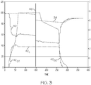
- FIG. 3 graphically depicts the values 38, 40 and 42 ST , 42 L and 42 SD in accordance with there herein described embodiments and operation of the gulp logic 34.
- the speed 46 of the APU turbine engine 12 is depicted to highlight the several states of APU 10 operation.
- the vertical black line is intended to represent a break in time so that the graphs may better represent the effect of oil consumption due to normal operation.
- raw oil quantity indication 40 illustrates a sharp drop corresponding to start up gulp.
- the gulp value 42 ST rises based upon the calculated difference between the oil quantity value, 38, and the raw oil quantity value, 40.
- the gulp value, 42 L is latched. With constant gulp value 42 L , the indicated oil quantity 38 decreases with time corresponding to oil consumption during use.
- the gulp value is unlatched and a shutdown gulp value, 42 SD is established during APU 10 shutdown.
- the gulp logic 34 may be modified to allow the gulp value 42 SD to increase during APU shutdown to account for the effects of reduced scavenge efficiency. Such a modification may improve the stability of the indicated oil quantity 38 during shutdown processes. Suitable logic would be required to account for an aborted shutdown process.
- the gulp logic 34 may additionally compensate for temperature expansion, and may further bracket all gulp values, i.e., truncate the gulp value at low and high limits, to prevent anomalous results due to data errors or other transient conditions.
- filtering and other data smoothing techniques may also be employed.
- indicated oil quantity value 38 In general, there is likely to be some variance between indicated oil quantity value 38 when the engine is running and just post engine shutdown.
- the quantity of oil that returns to the sump 20, and thus reflected in the raw oil quantity value 40 is dependent on oil temperature, age of the oil, de-oil capability, and other factors. If these factors are not accounted for, there may be an indicated oil quantity with some variation.
- FIG. 3 shows this condition in which more oil returns to the sump than was gulped on startup and some acceptable variation in indicated oil quantity 38 at shutdown, especially as the variation is greatly reduced as compared to existing systems and methodologies.
Landscapes
- Engineering & Computer Science (AREA)
- General Engineering & Computer Science (AREA)
- Mechanical Engineering (AREA)
- Chemical & Material Sciences (AREA)
- Combustion & Propulsion (AREA)
- Control Of Turbines (AREA)
- General Details Of Gearings (AREA)
- Lubrication Of Internal Combustion Engines (AREA)
Abstract
Description
- This invention generally relates to aircraft auxiliary power units (APUs), and more particularly, this invention relates to a method and system for accurate oil quantity determination and indication for an APU.
- The primary purpose of an aircraft APU is to provide power to start the main engines. Turbine engines must be accelerated to a high rotational speed to provide sufficient air compression for self-sustaining operation. Smaller jet engines are usually started by an electric motor, while larger engines are usually started by an air turbine motor. Before the engines are to be turned, the APU is started. Once the APU is running, it provides the power to start the aircraft's main engines.
- APUs are also used to run accessories while the engines are shut down. This allows the cabin to be comfortable while the passengers are boarding before the aircraft's engines are started. Electrical power is used to run systems for preflight checks. Some APUs are also connected to a hydraulic pump, allowing crews to operate hydraulic equipment prior to main engine start up. This function can also be used, on some aircraft, as a backup in flight in case of the loss of main engine power or hydraulic pressure.
- APUs fitted to extended-range twin-engine operations (ETOPS) aircraft are an important backup system, as they supply backup electricity, compressed air and hydraulic power in the highly unlikely, yet postulated event of a loss of main engine power or a failed main engine generator. As such, operators flying ETOPS legs are required to track and record oil consumption rates to ensure the APU is always serviced with sufficient oil for the duration of the flight mission. To support that need, APU controllers will display oil quantity on a flight deck display.
- Certain control systems have the capability of displaying quantity in discrete units, e.g., quarts or liters, or volume; however, displaying a consistent and accurate oil quantity while the APU is running is problematic. This is because these systems inadequately account for APU startup or shutdown gulp. To acquire a consistent oil quantity measurement with sufficient accuracy to permit ETOPS operation requires the aircraft maintenance operators to shut down the APU. Unfortunately, shutting down the APU is not preferred due to the increased time, work and inconvenience to restart the APU, e.g., hook up ground power, get a ground cart, etc. Therefore, aircraft manufacturers and operators are consistently looking for improved APU oil quantity measurement systems to support maintenance activities and reduce aircraft downtime.
- Accordingly, it is desirable to provide methods and systems to determine and indicate an accurate oil quantity of an APU, particularly as the APU is running. Furthermore, other desirable features and characteristics of the present invention will become apparent from the subsequent detailed description and the appended claims, taken in conjunction with the accompanying drawings and the foregoing technical field and background.
- An APU oil quantity indication system and method establishes oil gulp on APU start up, during operation and at shutdown. As a result, it is possible to determine and indicate APU oil quantity whether the APU is running or off. Furthermore, stable oil quantity indication is possible during engine transients such as startup and rolldown after shutdown.
- In one of the herein described embodiments, an APU oil gulp value may be established at APU startup and shutdown, respectively. The gulp value is combined with a continuous oil quantity indication to provide a stable oil quantity indication under all operating conditions, including transient conditions.
- In still another embodiment, a method of and system for determining and indicating APU oil quantity includes establishing an APU oil gulp value at various phases of APU operation. An APU oil quantity is determined by combining the oil gulp value with a continuous oil quantity value. The method may further include indicating the APU oil quantity value.
- The exemplary embodiments will hereinafter be described in conjunction with the following drawing figures, wherein like numerals denote like elements, and wherein:
-
FIG. 1 is a functional block diagram of an APU lubrication system including an APU oil quantity indication system in accordance with various embodiments; -
FIG. 2 is a functional block diagram of an APU control unit including an oil quantity indication system in accordance with various embodiments; and -
FIG. 3 graphic depiction of APU oil quantity. - The following detailed description is merely exemplary in nature and is not intended to limit the application and uses. Furthermore, there is no intention to be bound by any expressed or implied theory presented in the preceding technical field, background, brief summary or the following detailed description. It should be understood that throughout the drawings, corresponding reference numerals indicate like or corresponding parts and features. As used herein, the term system or module may refer to any combination or collection of mechanical and electrical hardware, software, firmware, electronic control component, processing logic, and/or processor device, individually or in any combination, including without limitation: application specific integrated circuit (ASIC), an electronic circuit, a processor (shared, dedicated, or group), memory that executes one or more software or firmware programs, a combinational logic circuit, and/or other suitable components that provide the described functionality.
- Embodiments of the invention may be described herein in terms of functional and/or logical block components and various processing steps. It should be appreciated that such block components may be realized by any number, combination or collection of mechanical and electrical hardware, software, and/or firmware components configured to perform the specified functions. For example, an embodiment of the invention may employ various combinations of electrical components, e.g., sensors, integrated circuit components, memory elements, digital signal processing elements, logic elements, look-up tables, or the like, which may carry out a variety of functions under the control of one or more microprocessors or other control devices. In addition, those skilled in the art will appreciate that embodiments of the present invention may be practiced in conjunction with any number of mechanical and/or electronic systems, and that the systems described herein are merely exemplary embodiment of the invention.
- For the sake of brevity, conventional components and techniques and other functional aspects of the systems (and the individual operating components of the systems) may not be described in detail herein. Furthermore, the connecting lines shown in the various figures contained herein are intended to represent example functional relationships and/or physical couplings between the various elements. It should be noted that many alternative or additional functional relationships or physical connections may be present in an embodiment of the invention.
-
FIG. 1 provides a simplified depiction of anAPU 10 that includes aturbine engine 12 and alubrication system 14. Theturbine engine 12 may be coupled to drive various equipment such as generators, pneumatic compressors, hydraulic pumps and the like generically indicated asdrive 16. Thelubrication system 14 provides lubricatingoil 18 from asump 20 to theturbine engine 12 and thedrive 16. Lubricatingoil 18 may be drawn from thesump 20 by apump 22 and is communicated to theturbine engine 12 and thedrive 16 via a cooler/filter 24. From theturbine engine 12 and thedrive 16, oil may be returned to thesump 20 viascavenge pump 26 and a cooler/filter 28. - The
lubrication system 14 includes an oil quantity sensor that provides an oil raw quantity indication in the form of an oil quantity value. For illustrative purposes, anoil quantity sensor 30 is shown disposed in association with thesump 20. Oil quantity sensing during operation of an APU is known, and any suitable sensor arrangement may be used to provide the oil raw quantity indication. Suitable oil quantity sensing arrangements include capacitive or linear variable differential transformer oil quantity sensors that generate an oil quantity value that is proportional to oil quantity in discrete units such as quarts or liters or in volume. -
FIG. 2 illustrates anAPU controller 32 that includesoil quantity sensor 30 andgulp value logic 34. The output of thesensor 30, as noted, is a rawoil quantity value 40. The output of thegulp value logic 34 is agulp value 42 determined at various stages of APU operation. The rawoil quantity value 40 and thegulp value 42 are combined, e.g., summed, at combininglogic 36 to provide an indicatedoil quantity value 38. The indicatedoil quantity value 38 may be in quarts, liters, volume or any other suitable set of units. - In accordance with various embodiments of the invention, the
gulp value logic 34 calculates an engine gulp on APU start, while running and at shutdown providing, for example, first, second and third gulp values. For purposes of discussion, and with reference toFIG. 2 , these values may be designated 42ST, 42L and 42SD. Combining the appropriate gulp value for the given operating state with the continuous rawoil quantity value 40 results in anoil quantity indication 38 that is substantially the same value when the APU is off, starting, running or rolling down after shut down, and which furthermore is an accurate indication of actual APU oil quantity. - When the APU is started, the
gulp logic 34 determines a start up gulp value, 42ST, as a difference between the lastoil quantity value 38 and the rawoil quantity value 40 at start up. This value is then combined, e.g., added, into the continuously updated rawoil quantity value 40. In this regard, thegulp logic 34 will store or reference the lastoil quantity value 38, e.g., as determined at shut down of theAPU 10, and use this value to determine a startup gulp value, 42ST corresponding toinitial APU 10 startup. During start up and until theAPU 10 has reached governed operational speed, thegulp logic 34 will periodically determine thegulp value 42ST as a difference between the lastoil quantity value 38 and the rawoil quantity value 40. With thegulp value 42ST continuously updated and added back to theraw oil quantity 40, a smooth and consistent oil quantity display is achieved as the APU goes from off to governed speed. - Once the
APU 10 achieves governed operating speed, i.e., theturbine engine 12 reaches its normal continuous operating speed, thegulp logic 34 latches the gulp value, 42L, to prevent the gulp term from continuing to increase as theAPU 10 consumes oil, i.e. the oil quantity display would not show the effects of oil consumption. Moreover, because it is expected that theAPU 10 will consume some amount of oil during operation, theAPU controller 32 will latch theoil quantity 38 at APU shutdown and use this oil quantity to calculate the gulp term, 42SD, during shutdown. This will result in smooth and consistent oil quantity display as theAPU 10 goes from governed speed to off. -
FIG. 3 graphically depicts thevalues gulp logic 34. In addition, thespeed 46 of theAPU turbine engine 12 is depicted to highlight the several states ofAPU 10 operation. The vertical black line is intended to represent a break in time so that the graphs may better represent the effect of oil consumption due to normal operation. - At
initial APU 10 start up, rawoil quantity indication 40 illustrates a sharp drop corresponding to start up gulp. Correspondingly, thegulp value 42ST rises based upon the calculated difference between the oil quantity value, 38, and the raw oil quantity value, 40. Once the APU reaches governed operation, the gulp value, 42L, is latched. Withconstant gulp value 42L, the indicatedoil quantity 38 decreases with time corresponding to oil consumption during use. After theAPU 10 has completed its preparation to shutdown, the gulp value is unlatched and a shutdown gulp value, 42SD is established duringAPU 10 shutdown. - The
gulp logic 34 may be modified to allow thegulp value 42SD to increase during APU shutdown to account for the effects of reduced scavenge efficiency. Such a modification may improve the stability of the indicatedoil quantity 38 during shutdown processes. Suitable logic would be required to account for an aborted shutdown process. Thegulp logic 34 may additionally compensate for temperature expansion, and may further bracket all gulp values, i.e., truncate the gulp value at low and high limits, to prevent anomalous results due to data errors or other transient conditions. The skilled person will further appreciate that filtering and other data smoothing techniques may also be employed. - In general, there is likely to be some variance between indicated
oil quantity value 38 when the engine is running and just post engine shutdown. The quantity of oil that returns to thesump 20, and thus reflected in the rawoil quantity value 40, is dependent on oil temperature, age of the oil, de-oil capability, and other factors. If these factors are not accounted for, there may be an indicated oil quantity with some variation.FIG. 3 shows this condition in which more oil returns to the sump than was gulped on startup and some acceptable variation inindicated oil quantity 38 at shutdown, especially as the variation is greatly reduced as compared to existing systems and methodologies. - While at least one exemplary embodiment has been presented in the foregoing detailed description, it should be appreciated that a vast number of variations exist. It should also be appreciated that the exemplary embodiment or exemplary embodiments are only examples, and are not intended to limit the scope, applicability, or configuration of the disclosure in any way. Rather, the foregoing detailed description will provide those skilled in the art with a convenient road map for implementing the exemplary embodiment or exemplary embodiments. It should be understood that various changes can be made in the function and arrangement of elements without departing from the scope of the disclosure as set forth in the appended claims and the legal equivalents thereof.
-
- 1. In an auxiliary power unit (APU)(10) a method of indicating oil quantity, the APU comprising a lubrication system (14) having lubricating oil (18) and a pump (22) to deliver the lubricating oil (18) to a turbine engine (12), the method comprising:
- determining a raw oil quantity value indicative of a quantity of lubricating oil (18) disposed within the lubrication system (14),
- establishing a gulp oil value (42); and
- determining an indicated oil quantity based upon the raw oil quantity value (40) and the gulp oil value (42).
- 2. The method of 1, wherein establishing a gulp oil value (42) comprises establishing a gulp oil value (42) during a startup phase of the APU (10).
- 3. The method of 1, wherein establishing a gulp oil value (42) comprises establishing a gulp oil value (42) during a shutdown phase of the APU (10).
- 4. The method of 1, wherein establishing a gulp oil value (42) comprises establishing a gulp oil value (42) during a startup phase of the APU (10) and latching the gulp oil value (42) during a governed operation phase of the APU (10).
- 5. The method of 1, wherein establishing a gulp oil value (42) comprises establishing a gulp oil value (42) based upon a shutdown indicated oil quantity (38) and a startup raw oil quantity value (40).
- 6. The method of 1, wherein determining an indicated oil quantity based upon the raw oil quantity value (40) and the gulp oil value (42) comprises combining the raw oil quantity value (40) and the gulp oil value (42).
- 7. The method of 1, wherein determining an indicated oil quantity based upon the raw oil quantity value (40) and the gulp oil value (42) comprises adding the raw oil quantity value (40) and the gulp oil value (42).
- 8. The method of 1, wherein establishing a gulp oil value comprises establishing a first gulp oil value (42ST) during a startup phase of the APU, a second gulp oil value (42L) during an operation phase of the APU and a third gulp oil value (42SD) during a shutdown phase of the APU.
- 9. The method of 8, further comprising determining a first gulp oil value (42ST) during a startup phase of the APU, a second gulp oil value (42L) during an operation phase of the APU and a third gulp oil value (42SD) during a shutdown phase of the APU.
- 10. A auxiliary power unit (APU) (10) adapted to provide an oil quantity indication in accordance with paragraphs 1-9.
- 11. An auxiliary power unit (APU) (10) having a lubrication system (14) having a sump (20) and pump (22) to deliver lubricating oil (18) from the sump (20) to a turbine engine (12),
a sensor (30) configured to provide a raw oil quantity value (40) indicative of a quantity of oil disposed within the sump (20); and
a controller (32), wherein the controller (32) is configured to establish a gulp oil value (42) and an indicated oil quantity based upon the raw oil quantity value (40) and the gulp oil value (42). - 12. An aircraft comprising an auxiliary power unit (10) in accordance with
paragraphs 10 or 11.
Claims (12)
- A method of indicating fluid quantity in a system, the method comprising:determining, via a controller, a raw fluid quantity value indicative of a quantity of fluid disposed within a storage receptacle of the system;establishing, via the controller, a gulp fluid value, including establishing a first gulp fluid value during a startup phase of the system, a second gulp fluid value during an operating phase of the system during a period when the system is running, and a third gulp fluid value during a shutdown phase of the system;determining, via the controller, an indicated fluid quantity based upon the raw fluid quantity value and the gulp fluid value; anddepicting, via the controller, the indicated fluid quantity on a display.
- The method of claim 1, wherein establishing a gulp fluid value comprises establishing the first gulp fluid value during a startup phase of the system and latching the second gulp fluid value during a governed operation phase of the system.
- The method of claim 1, wherein establishing, via the controller, the gulp fluid value comprises establishing the gulp fluid value based upon a shutdown indicated fluid quantity and a startup raw fluid quantity value.
- The method of claim 1, wherein determining, via the controller, the indicated fluid quantity based upon the raw fluid quantity value and the gulp fluid value comprises combining or adding the raw fluid quantity value and the gulp fluid value.
- The method of claim 1, further comprising determining, via the controller, a first raw fluid quantity during a startup phase of the APU, a second raw fluid quantity value during an operation phase of the system, and a third raw fluid quantity value during a shutdown phase of the system.
- The method of claim 1, wherein the fluid is a lubricant, a hydraulic fluid or water.
- The method of any of claims 1 to 5 wherein the term gulp fluid value is an oil gulp value and the term fluid quantity is an oil quantity.
- A turbine engine fluid quantity indicating system, comprising:
a lubrication system including a storage receptacle having lubricating fluid disposed therein and a pump to deliver the lubricating fluid from the storage receptacle to a turbine engine;a sensor configured to provide a raw fluid quantity value indicative of a quantity of the lubricating fluid disposed within the storage receptacle; anda controller, wherein the controller is configured to establish a gulp fluid value and an indicated fluid quantity based upon the raw fluid quantity value and the gulp fluid value, and to depict the indicated fluid quantity on a display,wherein, the gulp fluid value is based upon a first gulp fluid value during a startup phase of the turbine engine, a second gulp value during an operating phase of the turbine engine, and a third gulp fluid value during a shutdown phase of the turbine engine. - The system of claim 8, wherein the controller is configured to establish the gulp fluid value based upon a shutdown indicated fluid quantity and a startup raw fluid quantity value.
- The system of claim 8, wherein the controller is configured to establish the indicated fluid quantity based upon a combination or sum of the raw fluid quantity value and the gulp fluid value.
- The system of claim 8, wherein the fluid is a lubricant, a hydraulic fluid or water.
- The system of any of claims 7 to 10 wherein the term gulp fluid value is an oil gulp value and the term fluid quantity is an oil quantity.
Applications Claiming Priority (2)
| Application Number | Priority Date | Filing Date | Title |
|---|---|---|---|
| US15/041,168 US10378692B2 (en) | 2016-02-11 | 2016-02-11 | Method and system for APU oil level indication |
| EP17152075.2A EP3205839A1 (en) | 2016-02-11 | 2017-01-18 | Method and system for apu oil level indication |
Related Parent Applications (1)
| Application Number | Title | Priority Date | Filing Date |
|---|---|---|---|
| EP17152075.2A Division EP3205839A1 (en) | 2016-02-11 | 2017-01-18 | Method and system for apu oil level indication |
Publications (2)
| Publication Number | Publication Date |
|---|---|
| EP3653848A1 true EP3653848A1 (en) | 2020-05-20 |
| EP3653848B1 EP3653848B1 (en) | 2022-08-17 |
Family
ID=57860709
Family Applications (2)
| Application Number | Title | Priority Date | Filing Date |
|---|---|---|---|
| EP19208933.2A Active EP3653848B1 (en) | 2016-02-11 | 2017-01-18 | Method and system for apu oil level indication |
| EP17152075.2A Ceased EP3205839A1 (en) | 2016-02-11 | 2017-01-18 | Method and system for apu oil level indication |
Family Applications After (1)
| Application Number | Title | Priority Date | Filing Date |
|---|---|---|---|
| EP17152075.2A Ceased EP3205839A1 (en) | 2016-02-11 | 2017-01-18 | Method and system for apu oil level indication |
Country Status (2)
| Country | Link |
|---|---|
| US (1) | US10378692B2 (en) |
| EP (2) | EP3653848B1 (en) |
Families Citing this family (4)
| Publication number | Priority date | Publication date | Assignee | Title |
|---|---|---|---|---|
| CN110185908A (en) * | 2019-05-07 | 2019-08-30 | 山东省田庄煤矿有限公司 | A kind of winch self-acting lubricator |
| DE102022105782A1 (en) | 2022-03-11 | 2023-09-14 | Schwäbische Hüttenwerke Automotive GmbH | Fluid delivery system with separate filter module |
| DE102022105783A1 (en) * | 2022-03-11 | 2023-09-14 | Schwäbische Hüttenwerke Automotive GmbH | Fluid delivery system for supplying a machine unit with fluid |
| US12578013B2 (en) * | 2023-06-14 | 2026-03-17 | Borgwarner Inc. | Drive module assembly and drive module system including the same |
Citations (5)
| Publication number | Priority date | Publication date | Assignee | Title |
|---|---|---|---|---|
| DE4118896A1 (en) * | 1991-06-08 | 1992-12-10 | Mahle Gmbh | Monitoring and displaying appts. for oil level in reservoir e.g. of compressor - shows level for reference or under load state during other states using last level change for correction |
| US20090076677A1 (en) * | 2007-09-18 | 2009-03-19 | Hamilton Sundstrand Corporation | Method for Determination of Engine Lubrication Oil Consumption |
| EP2072762A1 (en) * | 2007-12-21 | 2009-06-24 | Techspace Aero SA | Method for controlling consumption and detecting leaks in a turbomachine lubrication system |
| US20110010069A1 (en) * | 2009-07-07 | 2011-01-13 | Honeywell International Inc. | Gas turbine engine oil consumption monitoring system and method |
| FR2958911A1 (en) * | 2010-04-19 | 2011-10-21 | Snecma | METHOD AND SYSTEM FOR MONITORING THE OIL LEVEL CONTAINED IN A RESERVOIR OF AN AIRCRAFT ENGINE |
Family Cites Families (3)
| Publication number | Priority date | Publication date | Assignee | Title |
|---|---|---|---|---|
| DE19602599C2 (en) | 1996-01-25 | 2002-07-11 | Daimler Chrysler Ag | Method for determining a quantity of liquid, in particular the quantity of engine oil, in a motor vehicle |
| EP2458161B1 (en) | 2010-11-24 | 2014-11-12 | Techspace Aero S.A. | Method for monitoring the oil system of a turbomachine |
| WO2013037865A1 (en) | 2011-09-15 | 2013-03-21 | Universite Libre De Bruxelles | Method and device for monitoring a lubrication system |
-
2016
- 2016-02-11 US US15/041,168 patent/US10378692B2/en active Active
-
2017
- 2017-01-18 EP EP19208933.2A patent/EP3653848B1/en active Active
- 2017-01-18 EP EP17152075.2A patent/EP3205839A1/en not_active Ceased
Patent Citations (5)
| Publication number | Priority date | Publication date | Assignee | Title |
|---|---|---|---|---|
| DE4118896A1 (en) * | 1991-06-08 | 1992-12-10 | Mahle Gmbh | Monitoring and displaying appts. for oil level in reservoir e.g. of compressor - shows level for reference or under load state during other states using last level change for correction |
| US20090076677A1 (en) * | 2007-09-18 | 2009-03-19 | Hamilton Sundstrand Corporation | Method for Determination of Engine Lubrication Oil Consumption |
| EP2072762A1 (en) * | 2007-12-21 | 2009-06-24 | Techspace Aero SA | Method for controlling consumption and detecting leaks in a turbomachine lubrication system |
| US20110010069A1 (en) * | 2009-07-07 | 2011-01-13 | Honeywell International Inc. | Gas turbine engine oil consumption monitoring system and method |
| FR2958911A1 (en) * | 2010-04-19 | 2011-10-21 | Snecma | METHOD AND SYSTEM FOR MONITORING THE OIL LEVEL CONTAINED IN A RESERVOIR OF AN AIRCRAFT ENGINE |
Also Published As
| Publication number | Publication date |
|---|---|
| US10378692B2 (en) | 2019-08-13 |
| EP3205839A1 (en) | 2017-08-16 |
| US20170234483A1 (en) | 2017-08-17 |
| EP3653848B1 (en) | 2022-08-17 |
Similar Documents
| Publication | Publication Date | Title |
|---|---|---|
| US8401760B2 (en) | Gas turbine engine oil consumption monitoring system and method | |
| US10378692B2 (en) | Method and system for APU oil level indication | |
| US9382849B2 (en) | Control of gas turbine engine | |
| US8887509B2 (en) | Liquid level monitoring and reporting system | |
| CN104343491B (en) | A kind of motor oil adds detection system and method | |
| CN102859133B (en) | Method and system for monitoring the level of oil contained in a tank of an aircraft engine | |
| CA2646685C (en) | Method for controlling the consumption and for detecting leaks in the lubrication system of a turbine engine | |
| EP2877719B1 (en) | System and method of lubricating and shutting down an internal combustion engine | |
| US9046040B2 (en) | Detection of the ingress of water or hail into a turbine engine | |
| US20130068562A1 (en) | Monitoring Overfilling In An Aeroplane Engine Lubrication System | |
| CN101346280B (en) | Aircraft auxiliary fuel tank system and method | |
| EP3159500A1 (en) | Auxiliary pump and gas turbine engine oil circuit monitoring system | |
| DE102011109636A1 (en) | METHOD OF MONITORING OIL IN A VEHICLE | |
| EP3696535A2 (en) | Active oil debris monitor particle detection and monitoring system | |
| US11192660B2 (en) | Method and system for APU oil level indication | |
| CN107387197B (en) | A kind of engine lubrication system, engine and vehicle | |
| CN117418917A (en) | Control device for mandatory pre-lubrication when starting a diesel locomotive and diesel locomotive | |
| US11230947B2 (en) | Gas turbine engine having oil level measurement system | |
| CN104420497A (en) | Method and system for automatically prompting maintenance of machine | |
| US20240159328A1 (en) | Monitoring an anti-leak valve in a jet engine | |
| Han et al. | Research on On-Line Monitoring Method of Lubricating Oil Consumption Rate of Aeroengine Based on QAR Data | |
| JP4184011B2 (en) | Operation state management system for power generation unit | |
| CN112963248A (en) | System for filling lubricating oil in working state of aircraft engine |
Legal Events
| Date | Code | Title | Description |
|---|---|---|---|
| PUAI | Public reference made under article 153(3) epc to a published international application that has entered the european phase |
Free format text: ORIGINAL CODE: 0009012 |
|
| STAA | Information on the status of an ep patent application or granted ep patent |
Free format text: STATUS: REQUEST FOR EXAMINATION WAS MADE |
|
| 17P | Request for examination filed |
Effective date: 20191113 |
|
| AC | Divisional application: reference to earlier application |
Ref document number: 3205839 Country of ref document: EP Kind code of ref document: P |
|
| AK | Designated contracting states |
Kind code of ref document: A1 Designated state(s): AL AT BE BG CH CY CZ DE DK EE ES FI FR GB GR HR HU IE IS IT LI LT LU LV MC MK MT NL NO PL PT RO RS SE SI SK SM TR |
|
| STAA | Information on the status of an ep patent application or granted ep patent |
Free format text: STATUS: EXAMINATION IS IN PROGRESS |
|
| 17Q | First examination report despatched |
Effective date: 20210217 |
|
| GRAP | Despatch of communication of intention to grant a patent |
Free format text: ORIGINAL CODE: EPIDOSNIGR1 |
|
| STAA | Information on the status of an ep patent application or granted ep patent |
Free format text: STATUS: GRANT OF PATENT IS INTENDED |
|
| INTG | Intention to grant announced |
Effective date: 20220421 |
|
| GRAS | Grant fee paid |
Free format text: ORIGINAL CODE: EPIDOSNIGR3 |
|
| GRAA | (expected) grant |
Free format text: ORIGINAL CODE: 0009210 |
|
| STAA | Information on the status of an ep patent application or granted ep patent |
Free format text: STATUS: THE PATENT HAS BEEN GRANTED |
|
| AC | Divisional application: reference to earlier application |
Ref document number: 3205839 Country of ref document: EP Kind code of ref document: P |
|
| AK | Designated contracting states |
Kind code of ref document: B1 Designated state(s): AL AT BE BG CH CY CZ DE DK EE ES FI FR GB GR HR HU IE IS IT LI LT LU LV MC MK MT NL NO PL PT RO RS SE SI SK SM TR |
|
| REG | Reference to a national code |
Ref country code: CH Ref legal event code: EP |
|
| REG | Reference to a national code |
Ref country code: DE Ref legal event code: R096 Ref document number: 602017060899 Country of ref document: DE |
|
| REG | Reference to a national code |
Ref country code: IE Ref legal event code: FG4D |
|
| REG | Reference to a national code |
Ref country code: AT Ref legal event code: REF Ref document number: 1512318 Country of ref document: AT Kind code of ref document: T Effective date: 20220915 |
|
| REG | Reference to a national code |
Ref country code: NL Ref legal event code: MP Effective date: 20220817 |
|
| REG | Reference to a national code |
Ref country code: LT Ref legal event code: MG9D |
|
| PG25 | Lapsed in a contracting state [announced via postgrant information from national office to epo] |
Ref country code: SE Free format text: LAPSE BECAUSE OF FAILURE TO SUBMIT A TRANSLATION OF THE DESCRIPTION OR TO PAY THE FEE WITHIN THE PRESCRIBED TIME-LIMIT Effective date: 20220817 Ref country code: RS Free format text: LAPSE BECAUSE OF FAILURE TO SUBMIT A TRANSLATION OF THE DESCRIPTION OR TO PAY THE FEE WITHIN THE PRESCRIBED TIME-LIMIT Effective date: 20220817 Ref country code: PT Free format text: LAPSE BECAUSE OF FAILURE TO SUBMIT A TRANSLATION OF THE DESCRIPTION OR TO PAY THE FEE WITHIN THE PRESCRIBED TIME-LIMIT Effective date: 20221219 Ref country code: NO Free format text: LAPSE BECAUSE OF FAILURE TO SUBMIT A TRANSLATION OF THE DESCRIPTION OR TO PAY THE FEE WITHIN THE PRESCRIBED TIME-LIMIT Effective date: 20221117 Ref country code: NL Free format text: LAPSE BECAUSE OF FAILURE TO SUBMIT A TRANSLATION OF THE DESCRIPTION OR TO PAY THE FEE WITHIN THE PRESCRIBED TIME-LIMIT Effective date: 20220817 Ref country code: LV Free format text: LAPSE BECAUSE OF FAILURE TO SUBMIT A TRANSLATION OF THE DESCRIPTION OR TO PAY THE FEE WITHIN THE PRESCRIBED TIME-LIMIT Effective date: 20220817 Ref country code: LT Free format text: LAPSE BECAUSE OF FAILURE TO SUBMIT A TRANSLATION OF THE DESCRIPTION OR TO PAY THE FEE WITHIN THE PRESCRIBED TIME-LIMIT Effective date: 20220817 Ref country code: FI Free format text: LAPSE BECAUSE OF FAILURE TO SUBMIT A TRANSLATION OF THE DESCRIPTION OR TO PAY THE FEE WITHIN THE PRESCRIBED TIME-LIMIT Effective date: 20220817 |
|
| REG | Reference to a national code |
Ref country code: AT Ref legal event code: MK05 Ref document number: 1512318 Country of ref document: AT Kind code of ref document: T Effective date: 20220817 |
|
| PG25 | Lapsed in a contracting state [announced via postgrant information from national office to epo] |
Ref country code: PL Free format text: LAPSE BECAUSE OF FAILURE TO SUBMIT A TRANSLATION OF THE DESCRIPTION OR TO PAY THE FEE WITHIN THE PRESCRIBED TIME-LIMIT Effective date: 20220817 Ref country code: IS Free format text: LAPSE BECAUSE OF FAILURE TO SUBMIT A TRANSLATION OF THE DESCRIPTION OR TO PAY THE FEE WITHIN THE PRESCRIBED TIME-LIMIT Effective date: 20221217 Ref country code: HR Free format text: LAPSE BECAUSE OF FAILURE TO SUBMIT A TRANSLATION OF THE DESCRIPTION OR TO PAY THE FEE WITHIN THE PRESCRIBED TIME-LIMIT Effective date: 20220817 Ref country code: GR Free format text: LAPSE BECAUSE OF FAILURE TO SUBMIT A TRANSLATION OF THE DESCRIPTION OR TO PAY THE FEE WITHIN THE PRESCRIBED TIME-LIMIT Effective date: 20221118 |
|
| PG25 | Lapsed in a contracting state [announced via postgrant information from national office to epo] |
Ref country code: SM Free format text: LAPSE BECAUSE OF FAILURE TO SUBMIT A TRANSLATION OF THE DESCRIPTION OR TO PAY THE FEE WITHIN THE PRESCRIBED TIME-LIMIT Effective date: 20220817 Ref country code: RO Free format text: LAPSE BECAUSE OF FAILURE TO SUBMIT A TRANSLATION OF THE DESCRIPTION OR TO PAY THE FEE WITHIN THE PRESCRIBED TIME-LIMIT Effective date: 20220817 Ref country code: ES Free format text: LAPSE BECAUSE OF FAILURE TO SUBMIT A TRANSLATION OF THE DESCRIPTION OR TO PAY THE FEE WITHIN THE PRESCRIBED TIME-LIMIT Effective date: 20220817 Ref country code: DK Free format text: LAPSE BECAUSE OF FAILURE TO SUBMIT A TRANSLATION OF THE DESCRIPTION OR TO PAY THE FEE WITHIN THE PRESCRIBED TIME-LIMIT Effective date: 20220817 Ref country code: CZ Free format text: LAPSE BECAUSE OF FAILURE TO SUBMIT A TRANSLATION OF THE DESCRIPTION OR TO PAY THE FEE WITHIN THE PRESCRIBED TIME-LIMIT Effective date: 20220817 Ref country code: AT Free format text: LAPSE BECAUSE OF FAILURE TO SUBMIT A TRANSLATION OF THE DESCRIPTION OR TO PAY THE FEE WITHIN THE PRESCRIBED TIME-LIMIT Effective date: 20220817 |
|
| REG | Reference to a national code |
Ref country code: DE Ref legal event code: R097 Ref document number: 602017060899 Country of ref document: DE |
|
| PG25 | Lapsed in a contracting state [announced via postgrant information from national office to epo] |
Ref country code: SK Free format text: LAPSE BECAUSE OF FAILURE TO SUBMIT A TRANSLATION OF THE DESCRIPTION OR TO PAY THE FEE WITHIN THE PRESCRIBED TIME-LIMIT Effective date: 20220817 Ref country code: EE Free format text: LAPSE BECAUSE OF FAILURE TO SUBMIT A TRANSLATION OF THE DESCRIPTION OR TO PAY THE FEE WITHIN THE PRESCRIBED TIME-LIMIT Effective date: 20220817 |
|
| PLBE | No opposition filed within time limit |
Free format text: ORIGINAL CODE: 0009261 |
|
| STAA | Information on the status of an ep patent application or granted ep patent |
Free format text: STATUS: NO OPPOSITION FILED WITHIN TIME LIMIT |
|
| PG25 | Lapsed in a contracting state [announced via postgrant information from national office to epo] |
Ref country code: AL Free format text: LAPSE BECAUSE OF FAILURE TO SUBMIT A TRANSLATION OF THE DESCRIPTION OR TO PAY THE FEE WITHIN THE PRESCRIBED TIME-LIMIT Effective date: 20220817 |
|
| P01 | Opt-out of the competence of the unified patent court (upc) registered |
Effective date: 20230525 |
|
| 26N | No opposition filed |
Effective date: 20230519 |
|
| PG25 | Lapsed in a contracting state [announced via postgrant information from national office to epo] |
Ref country code: SI Free format text: LAPSE BECAUSE OF FAILURE TO SUBMIT A TRANSLATION OF THE DESCRIPTION OR TO PAY THE FEE WITHIN THE PRESCRIBED TIME-LIMIT Effective date: 20220817 |
|
| REG | Reference to a national code |
Ref country code: CH Ref legal event code: PL |
|
| GBPC | Gb: european patent ceased through non-payment of renewal fee |
Effective date: 20230118 |
|
| PG25 | Lapsed in a contracting state [announced via postgrant information from national office to epo] |
Ref country code: LU Free format text: LAPSE BECAUSE OF NON-PAYMENT OF DUE FEES Effective date: 20230118 |
|
| REG | Reference to a national code |
Ref country code: BE Ref legal event code: MM Effective date: 20230131 |
|
| PG25 | Lapsed in a contracting state [announced via postgrant information from national office to epo] |
Ref country code: LI Free format text: LAPSE BECAUSE OF NON-PAYMENT OF DUE FEES Effective date: 20230131 Ref country code: GB Free format text: LAPSE BECAUSE OF NON-PAYMENT OF DUE FEES Effective date: 20230118 Ref country code: CH Free format text: LAPSE BECAUSE OF NON-PAYMENT OF DUE FEES Effective date: 20230131 |
|
| PG25 | Lapsed in a contracting state [announced via postgrant information from national office to epo] |
Ref country code: FR Free format text: LAPSE BECAUSE OF NON-PAYMENT OF DUE FEES Effective date: 20230131 Ref country code: BE Free format text: LAPSE BECAUSE OF NON-PAYMENT OF DUE FEES Effective date: 20230131 |
|
| PG25 | Lapsed in a contracting state [announced via postgrant information from national office to epo] |
Ref country code: IE Free format text: LAPSE BECAUSE OF NON-PAYMENT OF DUE FEES Effective date: 20230118 |
|
| PG25 | Lapsed in a contracting state [announced via postgrant information from national office to epo] |
Ref country code: IT Free format text: LAPSE BECAUSE OF FAILURE TO SUBMIT A TRANSLATION OF THE DESCRIPTION OR TO PAY THE FEE WITHIN THE PRESCRIBED TIME-LIMIT Effective date: 20220817 |
|
| PG25 | Lapsed in a contracting state [announced via postgrant information from national office to epo] |
Ref country code: MC Free format text: LAPSE BECAUSE OF FAILURE TO SUBMIT A TRANSLATION OF THE DESCRIPTION OR TO PAY THE FEE WITHIN THE PRESCRIBED TIME-LIMIT Effective date: 20220817 |
|
| PG25 | Lapsed in a contracting state [announced via postgrant information from national office to epo] |
Ref country code: MC Free format text: LAPSE BECAUSE OF FAILURE TO SUBMIT A TRANSLATION OF THE DESCRIPTION OR TO PAY THE FEE WITHIN THE PRESCRIBED TIME-LIMIT Effective date: 20220817 |
|
| PG25 | Lapsed in a contracting state [announced via postgrant information from national office to epo] |
Ref country code: BG Free format text: LAPSE BECAUSE OF FAILURE TO SUBMIT A TRANSLATION OF THE DESCRIPTION OR TO PAY THE FEE WITHIN THE PRESCRIBED TIME-LIMIT Effective date: 20220817 |
|
| PG25 | Lapsed in a contracting state [announced via postgrant information from national office to epo] |
Ref country code: BG Free format text: LAPSE BECAUSE OF FAILURE TO SUBMIT A TRANSLATION OF THE DESCRIPTION OR TO PAY THE FEE WITHIN THE PRESCRIBED TIME-LIMIT Effective date: 20220817 |
|
| PG25 | Lapsed in a contracting state [announced via postgrant information from national office to epo] |
Ref country code: CY Free format text: LAPSE BECAUSE OF FAILURE TO SUBMIT A TRANSLATION OF THE DESCRIPTION OR TO PAY THE FEE WITHIN THE PRESCRIBED TIME-LIMIT; INVALID AB INITIO Effective date: 20170118 |
|
| PG25 | Lapsed in a contracting state [announced via postgrant information from national office to epo] |
Ref country code: HU Free format text: LAPSE BECAUSE OF FAILURE TO SUBMIT A TRANSLATION OF THE DESCRIPTION OR TO PAY THE FEE WITHIN THE PRESCRIBED TIME-LIMIT; INVALID AB INITIO Effective date: 20170118 |
|
| PG25 | Lapsed in a contracting state [announced via postgrant information from national office to epo] |
Ref country code: TR Free format text: LAPSE BECAUSE OF FAILURE TO SUBMIT A TRANSLATION OF THE DESCRIPTION OR TO PAY THE FEE WITHIN THE PRESCRIBED TIME-LIMIT Effective date: 20220817 |
|
| PGFP | Annual fee paid to national office [announced via postgrant information from national office to epo] |
Ref country code: DE Payment date: 20260127 Year of fee payment: 10 |