EP3653840A1 - Tip clearance sensor - Google Patents
Tip clearance sensor Download PDFInfo
- Publication number
- EP3653840A1 EP3653840A1 EP19204272.9A EP19204272A EP3653840A1 EP 3653840 A1 EP3653840 A1 EP 3653840A1 EP 19204272 A EP19204272 A EP 19204272A EP 3653840 A1 EP3653840 A1 EP 3653840A1
- Authority
- EP
- European Patent Office
- Prior art keywords
- capacitor
- resistor
- composite body
- ceramic
- layers
- Prior art date
- Legal status (The legal status is an assumption and is not a legal conclusion. Google has not performed a legal analysis and makes no representation as to the accuracy of the status listed.)
- Granted
Links
Images




Classifications
-
- F—MECHANICAL ENGINEERING; LIGHTING; HEATING; WEAPONS; BLASTING
- F01—MACHINES OR ENGINES IN GENERAL; ENGINE PLANTS IN GENERAL; STEAM ENGINES
- F01D—NON-POSITIVE DISPLACEMENT MACHINES OR ENGINES, e.g. STEAM TURBINES
- F01D11/00—Preventing or minimising internal leakage of working-fluid, e.g. between stages
- F01D11/08—Preventing or minimising internal leakage of working-fluid, e.g. between stages for sealing space between rotor blade tips and stator
- F01D11/14—Adjusting or regulating tip-clearance, i.e. distance between rotor-blade tips and stator casing
-
- F—MECHANICAL ENGINEERING; LIGHTING; HEATING; WEAPONS; BLASTING
- F01—MACHINES OR ENGINES IN GENERAL; ENGINE PLANTS IN GENERAL; STEAM ENGINES
- F01D—NON-POSITIVE DISPLACEMENT MACHINES OR ENGINES, e.g. STEAM TURBINES
- F01D21/00—Shutting-down of machines or engines, e.g. in emergency; Regulating, controlling, or safety means not otherwise provided for
- F01D21/003—Arrangements for testing or measuring
-
- F—MECHANICAL ENGINEERING; LIGHTING; HEATING; WEAPONS; BLASTING
- F01—MACHINES OR ENGINES IN GENERAL; ENGINE PLANTS IN GENERAL; STEAM ENGINES
- F01D—NON-POSITIVE DISPLACEMENT MACHINES OR ENGINES, e.g. STEAM TURBINES
- F01D17/00—Regulating or controlling by varying flow
- F01D17/02—Arrangement of sensing elements
-
- F—MECHANICAL ENGINEERING; LIGHTING; HEATING; WEAPONS; BLASTING
- F01—MACHINES OR ENGINES IN GENERAL; ENGINE PLANTS IN GENERAL; STEAM ENGINES
- F01D—NON-POSITIVE DISPLACEMENT MACHINES OR ENGINES, e.g. STEAM TURBINES
- F01D5/00—Blades; Blade-carrying members; Heating, heat-insulating, cooling or antivibration means on the blades or the members
- F01D5/12—Blades
- F01D5/14—Form or construction
- F01D5/20—Specially-shaped blade tips to seal space between tips and stator
-
- G—PHYSICS
- G01—MEASURING; TESTING
- G01B—MEASURING LENGTH, THICKNESS OR SIMILAR LINEAR DIMENSIONS; MEASURING ANGLES; MEASURING AREAS; MEASURING IRREGULARITIES OF SURFACES OR CONTOURS
- G01B7/00—Measuring arrangements characterised by the use of electric or magnetic techniques
- G01B7/14—Measuring arrangements characterised by the use of electric or magnetic techniques for measuring distance or clearance between spaced objects or spaced apertures
-
- G—PHYSICS
- G01—MEASURING; TESTING
- G01N—INVESTIGATING OR ANALYSING MATERIALS BY DETERMINING THEIR CHEMICAL OR PHYSICAL PROPERTIES
- G01N17/00—Investigating resistance of materials to the weather, to corrosion, or to light
- G01N17/006—Investigating resistance of materials to the weather, to corrosion, or to light of metals
-
- G—PHYSICS
- G01—MEASURING; TESTING
- G01P—MEASURING LINEAR OR ANGULAR SPEED, ACCELERATION, DECELERATION, OR SHOCK; INDICATING PRESENCE, ABSENCE, OR DIRECTION, OF MOVEMENT
- G01P3/00—Measuring linear or angular speed; Measuring differences of linear or angular speeds
- G01P3/42—Devices characterised by the use of electric or magnetic means
- G01P3/44—Devices characterised by the use of electric or magnetic means for measuring angular speed
-
- F—MECHANICAL ENGINEERING; LIGHTING; HEATING; WEAPONS; BLASTING
- F05—INDEXING SCHEMES RELATING TO ENGINES OR PUMPS IN VARIOUS SUBCLASSES OF CLASSES F01-F04
- F05D—INDEXING SCHEME FOR ASPECTS RELATING TO NON-POSITIVE-DISPLACEMENT MACHINES OR ENGINES, GAS-TURBINES OR JET-PROPULSION PLANTS
- F05D2220/00—Application
- F05D2220/30—Application in turbines
- F05D2220/32—Application in turbines in gas turbines
-
- F—MECHANICAL ENGINEERING; LIGHTING; HEATING; WEAPONS; BLASTING
- F05—INDEXING SCHEMES RELATING TO ENGINES OR PUMPS IN VARIOUS SUBCLASSES OF CLASSES F01-F04
- F05D—INDEXING SCHEME FOR ASPECTS RELATING TO NON-POSITIVE-DISPLACEMENT MACHINES OR ENGINES, GAS-TURBINES OR JET-PROPULSION PLANTS
- F05D2240/00—Components
- F05D2240/10—Stators
- F05D2240/11—Shroud seal segments
-
- F—MECHANICAL ENGINEERING; LIGHTING; HEATING; WEAPONS; BLASTING
- F05—INDEXING SCHEMES RELATING TO ENGINES OR PUMPS IN VARIOUS SUBCLASSES OF CLASSES F01-F04
- F05D—INDEXING SCHEME FOR ASPECTS RELATING TO NON-POSITIVE-DISPLACEMENT MACHINES OR ENGINES, GAS-TURBINES OR JET-PROPULSION PLANTS
- F05D2260/00—Function
- F05D2260/80—Diagnostics
-
- F—MECHANICAL ENGINEERING; LIGHTING; HEATING; WEAPONS; BLASTING
- F05—INDEXING SCHEMES RELATING TO ENGINES OR PUMPS IN VARIOUS SUBCLASSES OF CLASSES F01-F04
- F05D—INDEXING SCHEME FOR ASPECTS RELATING TO NON-POSITIVE-DISPLACEMENT MACHINES OR ENGINES, GAS-TURBINES OR JET-PROPULSION PLANTS
- F05D2270/00—Control
- F05D2270/80—Devices generating input signals, e.g. transducers, sensors, cameras or strain gauges
-
- F—MECHANICAL ENGINEERING; LIGHTING; HEATING; WEAPONS; BLASTING
- F05—INDEXING SCHEMES RELATING TO ENGINES OR PUMPS IN VARIOUS SUBCLASSES OF CLASSES F01-F04
- F05D—INDEXING SCHEME FOR ASPECTS RELATING TO NON-POSITIVE-DISPLACEMENT MACHINES OR ENGINES, GAS-TURBINES OR JET-PROPULSION PLANTS
- F05D2270/00—Control
- F05D2270/80—Devices generating input signals, e.g. transducers, sensors, cameras or strain gauges
- F05D2270/821—Displacement measuring means, e.g. inductive
-
- F—MECHANICAL ENGINEERING; LIGHTING; HEATING; WEAPONS; BLASTING
- F05—INDEXING SCHEMES RELATING TO ENGINES OR PUMPS IN VARIOUS SUBCLASSES OF CLASSES F01-F04
- F05D—INDEXING SCHEME FOR ASPECTS RELATING TO NON-POSITIVE-DISPLACEMENT MACHINES OR ENGINES, GAS-TURBINES OR JET-PROPULSION PLANTS
- F05D2300/00—Materials; Properties thereof
- F05D2300/60—Properties or characteristics given to material by treatment or manufacturing
- F05D2300/601—Fabrics
- F05D2300/6012—Woven fabrics
-
- F—MECHANICAL ENGINEERING; LIGHTING; HEATING; WEAPONS; BLASTING
- F05—INDEXING SCHEMES RELATING TO ENGINES OR PUMPS IN VARIOUS SUBCLASSES OF CLASSES F01-F04
- F05D—INDEXING SCHEME FOR ASPECTS RELATING TO NON-POSITIVE-DISPLACEMENT MACHINES OR ENGINES, GAS-TURBINES OR JET-PROPULSION PLANTS
- F05D2300/00—Materials; Properties thereof
- F05D2300/60—Properties or characteristics given to material by treatment or manufacturing
- F05D2300/603—Composites; e.g. fibre-reinforced
-
- F—MECHANICAL ENGINEERING; LIGHTING; HEATING; WEAPONS; BLASTING
- F05—INDEXING SCHEMES RELATING TO ENGINES OR PUMPS IN VARIOUS SUBCLASSES OF CLASSES F01-F04
- F05D—INDEXING SCHEME FOR ASPECTS RELATING TO NON-POSITIVE-DISPLACEMENT MACHINES OR ENGINES, GAS-TURBINES OR JET-PROPULSION PLANTS
- F05D2300/00—Materials; Properties thereof
- F05D2300/60—Properties or characteristics given to material by treatment or manufacturing
- F05D2300/603—Composites; e.g. fibre-reinforced
- F05D2300/6032—Metal matrix composites [MMC]
-
- F—MECHANICAL ENGINEERING; LIGHTING; HEATING; WEAPONS; BLASTING
- F05—INDEXING SCHEMES RELATING TO ENGINES OR PUMPS IN VARIOUS SUBCLASSES OF CLASSES F01-F04
- F05D—INDEXING SCHEME FOR ASPECTS RELATING TO NON-POSITIVE-DISPLACEMENT MACHINES OR ENGINES, GAS-TURBINES OR JET-PROPULSION PLANTS
- F05D2300/00—Materials; Properties thereof
- F05D2300/60—Properties or characteristics given to material by treatment or manufacturing
- F05D2300/603—Composites; e.g. fibre-reinforced
- F05D2300/6033—Ceramic matrix composites [CMC]
Definitions
- This disclosure relates to sensors and, in particular, to blade tip sensors.
- a radio frequency sensor including a composite body including a plurality of ceramic fibers in a plurality of layers.
- the radio frequency sensor further includes a resistor-capacitor circuit embedded in the composite body.
- a portion of the composite body forms a dielectric of a capacitor of the resistor-capacitor circuit.
- the capacitor has a capacitance that depends on a distance between the capacitor and a blade of a rotor of a gas turbine engine.
- the composite body includes a metallic mesh separating the capacitor and a resistor of the resistor-capacitor circuit.
- a layer of the composite body includes a metallic mesh that is an electrode in the resistor-capacitor circuit.
- the composite body includes a metallic mesh on opposite sides of a section of the ceramic fibers of one of the layers that is located between two other of the layers.
- the metallic mesh forms electrodes of the capacitor.
- the section of the ceramic fibers is part of a dielectric of the capacitor.
- the composite body includes a metallic mesh on opposite sides of a section of electrically conductive fibers of one of the layers that is located between two other of the layers.
- the metallic mesh form electrodes of a resistor of the resistor-capacitor circuit.
- the electrically conductive fibers form a resistive element of the resistor.
- the composite body includes electrically conductive fibers.
- the composite body includes a ceramic matrix composite body.
- a method to form a blade tip sensor includes arranging a plurality of ceramic fibers in a plurality of layers to form a porous ceramic preform.
- the method further includes forming the porous ceramic preform into a ceramic matrix composite body by melt and/or vapor infiltration. At least one of the ceramic fibers is part of a capacitor of a bridge-network circuit embedded in the ceramic matrix composite body.
- the bridge-network circuit includes a first resistor-capacitor circuit on a first branch and a second resistor-capacitor circuit on a second branch.
- the capacitor is included in the first resistor-capacitor circuit or the second resistor-capacitor circuit.
- the capacitor has a capacitance that depends on a distance between the capacitor and a blade of a rotor of a gas turbine engine.
- the method further includes including a metallic mesh for electromagnetic shielding in the porous ceramic preform before forming the porous ceramic preform into the ceramic matrix composite body.
- the method further includes including a metallic mesh for an electrode in the porous ceramic preform before forming the porous ceramic preform into the ceramic matrix composite body.
- the method further includes including a metallic mesh on opposite sides of a section of the ceramic fibers of one of the layers that is located between two other of the layers.
- the metallic mesh forms electrodes of the capacitor, and the section of the ceramic fibers is part of a dielectric of the capacitor.
- the method further includes including a metallic mesh on opposite sides of a section of electrically conductive fibers of one of the layers that is located between two other of the layers.
- the metallic mesh form electrodes of a resistor in the first resistor-capacitor circuit or the second resistor-capacitor circuit, and the electrically conductive fibers form a resistive element of the resistor.
- the electrically conductive fibers include silicon carbide fibers.
- the ceramic matrix composite body includes a section of an engine shroud.
- a blade tip sensor including a bridge-network circuit including a first resistor-capacitor circuit on a first branch and a second resistor-capacitor circuit on a second branch.
- the bridge-network circuit is included in a composite body.
- Each of the first resistor-capacitor circuit and the second resistor-capacitor circuit includes a corresponding capacitor having a capacitance that depends on a distance between the corresponding capacitor and a blade of a rotor.
- the blade tip sensor may provide one or more improvements in real-time tip control.
- the blade tip sensor includes a transceiver configured to generate and transmit an excitation signal at a plurality of frequencies to the bridge-network circuit.
- the blade tip sensor further includes a processor configured to determine blade tip clearance from a capacitance derived from a measurement signal received from the bridge-network circuit.
- Determining tip clearance may enable maintaining concentricity. Maintaining concentricity may improve fuel efficiency and decrease maintenance issues.
- the blade tip sensor includes a processor configured to detect wear on the blade from a measurement signal received from the bridge-network circuit.
- the wear can be implemented into an equipment health monitory system to indicate when maintenance is required.
- the blade tip sensor includes a processor configured to determine engine speed from a measurement signal received from the bridge-network circuit.
- the processor may send a request to disable fuel delivery in response to detecting an over-speed condition.
- the blade tip sensor further includes a processor configured to detect shaft break based on a measurement signal received from the bridge-network circuit.
- the blade tip sensor may have a lower cost than more complicated electronic systems such as microwave or optical speed measurement systems.
- a radio frequency sensor comprising a composite body and a resistor-capacitor circuit embedded in the composite body.
- the composite body may be, for example, a ceramic matrix composite (CMC) body such as a CMC engine shroud.
- CMC ceramic matrix composite
- a portion of the composite body forms a dielectric of a capacitor of the resistor-capacitor circuit, and the capacitor has a capacitance that depends on a distance between the capacitor and a blade of a rotor of gas turbine engine.
- a blade tip sensor comprising a bridge-network circuit included in a composite body.
- the bridge-network circuit comprises a first resistor-capacitor circuit on a first branch and a second resistor-capacitor circuit on a second branch.
- Each of the first resistor-capacitor circuit and the second resistor-capacitor circuit includes a corresponding capacitor having a capacitance that depends on a distance between the corresponding capacitor and a blade of a rotor.
- a method to form a blade tip sensor is provided.
- Ceramic fibers are arranged in in layers to form a porous ceramic preform.
- the ceramic preform is formed into a ceramic matrix composite body by melt and/or vapor infiltration.
- At least one of the ceramic fibers is part of a capacitor of a bridge-network circuit embedded in the ceramic matrix composite body.
- the bridge-network circuit comprises a first resistor-capacitor circuit on a first branch and a second resistor-capacitor circuit on a second branch.
- the capacitor is included in the first resistor-capacitor circuit or the second resistor-capacitor circuit.
- the capacitor has a capacitance that depends on a distance between the capacitor and a blade of a rotor of gas turbine engine.
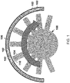
- FIG. 1 is a cross-sectional view of a gas turbine engine that includes radio frequency (RF) sensors 102 integrated into a ceramic matrix composite (CMC) engine shroud 106.
- the RF sensors 102 are arranged at various locations around the CMC engine shroud 106.
- blades 104 of a rotor 108 may rotate so that tips 110 of the blades 104 pass the RF sensors 102.
- 3 to 4 pairs of the RF sensors 102 may be located circumferentially around the CMC engine shroud 106.
- Such an arrangement enables detection of engine casing deflection and, together with a tip clearance control system, enables maintaining concentricity. Maintaining concentricity may improve fuel efficiency and decrease maintenance issues.
- FIG. 1 The cross-sectional view of the gas turbine engine shown in FIG. 1 is of a cross-section taken in plane perpendicular to a flow path of a fluid that flows through the rotor 108 and past the blades 104.
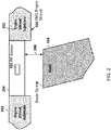
- FIG. 2 is a cross-sectional view of the gas turbine engine taken in a plane parallel to the flow path.
- the blade tip 110 of one of the blades 104 is shown in proximity to the CMC engine shroud 106 and, in particular, in proximity to one of the RF sensors 102.
- the CMC engine shroud 106 includes an engine shroud substrate 202 and an abradable substrate 204 located in the engine shroud substrate 202.
- the abradable substrate 204 is positioned radially outward from the blade tip 110 and has an exposed surface facing the blade tip 110. A distance between the blade tip 110 and the abradable substrate 204 is referred to as tip clearance 206 or blade tip clearance.
- tip clearance 206 A distance between the blade tip 110 and the abradable substrate 204 is referred to as tip clearance 206 or blade tip clearance.
- One of the RF sensors 102 is shown embedded in the abradable substrate 204 in FIG. 2 .
- FIG. 3 illustrates a circuit diagram of a blade tip sensor 300 or blade tip sensor system, which includes two of the RF sensors 102 arranged in a bridge-network circuit 304 and an RF transceiver 302.
- the bridge-network circuit 304 is embedded in a ceramic matric composite body, such as the CMC engine shroud 106.
- the RF transceiver 302 may be located in a different location than the two RF sensors 102.
- the RF transceiver 302 may be located in a cooler location than the RF sensors 102.
- the RF transceiver 302 may be any device configured to generate and transmit an excitation signal to nodes V exc + and V exc - of the bridge-network circuit 304, and to receive measurement signals from nodes V D1 and V D2 of the bridge-network circuit 304.
- the excitation signal may have a predetermined frequency.
- the excitation signal may be sine wave, a sawtooth wave, a square wave, or any other shaped periodic signal.
- the RF transceiver 302 includes an RF transmitter-receiver integrated circuit 308 ("RF transceiver IC") and a Class C Amplifier 306.
- the RF transceiver IC 308 is configured to generate and transmit the excitation signal over lines T x + and T x - to the bridge-network circuit 304.
- the excitation signal is fed through the Class C amplifier 306 to drive the bridge-network circuit 304 at a relatively high power and relatively high frequency, and to naturally modulate a carrier frequency, such as 100 MHz.
- the RF transceiver IC 308 includes a built-in Class C amplifier and the Class C amplifier 306 that is discrete from the RF transceiver IC 308 is not included in the RF transceiver 302.
- the RF transceiver 302 generates and transmits a non-truncated excitation signal and no Class C amplifier is included in the RF transceiver 302.
- the RF transceiver IC 308 is configured to receive the measurement signals from the bridge-network circuit 304 over lines R x + and R x -.
- the RF transceiver IC 308 may include a DAC (digital to analog converter) that converts the received measurement signals into digital signals.
- Model ADRV9009 has a relatively wide frequency range, relatively wide bandwidth as a single chip radio.
- a first one of the RF sensors 102 includes a first resistor-capacitor circuit
- a second one of the RF sensors 102 includes a second resistor-capacitor circuit.
- the bridge-network circuit 304 includes the first resistor-capacitor circuit on a first branch and the second resistor-capacitor circuit on a second branch.
- the first resistor-capacitor circuit on the first branch includes a resistor R1 and a capacitor C1 connected in series.
- the second resistor-capacitor circuit on the second branch includes a resistor R2 and a capacitor C2 connected in series.
- Current I1 may flow through the first branch, and current I2 may flow through the second branch.
- the bridge-network circuit 304 in the illustrated example is in a half bridge configuration.
- the bridge-network circuit 304 may include any number of active and/or passive RF impedances.
- the bridge-network circuit 304 in FIG. 3 includes two active components that act as variable capacitance sensors (C1 and C2) and two fixed resistors (R1 and R2).
- C1 and C2 variable capacitance sensors
- R1 and R2 fixed resistors
- the value of the capacitance sensor - in other words, the effective capacitance of the capacitor C1 or C2 - varies as the distance between the capacitor C1 or C2 and the blade tip 110 increases or decreases.
- the capacitor C1 or C2 has a capacitance that depends on a distance between the capacitor C1 or C2 and the blade tip 110.
- the capacitance of the capacitor C1 or C2 is an indicator of the size of the tip clearance 206.
- the capacitor C1 and C2 may be screened to attenuate effects of parasitic capacitance in integration with the engine.
- each of the RF sensors 102 may preferably include a capacitive sensor as compared to an inductive sensor. This is due to the material limitations associated with the Curie Temperatures of magnetic materials.
- the blades 104 may comprise a non-metallic or a composite material, the capacitive effects may be easier to process with more accuracy.
- the RF sensors 102 may be located strategically to capture passings of the blade 104 with a local maxima and minima of measured capacitances and to operate the bridge-network circuit 304 at a higher level of sensitivity than may be possible otherwise.
- the RF transceiver 302 may operate in a 100 to 300 MHz frequency band or any other suitable frequency band.
- the driving signal may have a frequency of 100 MHz, 120 MHz, and/or any other frequency within the operable frequency band.
- the fixed resistances, R1 and R2 in the RF sensors 102 may be on the order of 100 ohms.
- the capacitor C1 or C2 in each of the RF sensors 102 may have a capacitance in a range of 1 to 20 pF.
- the bridge-network circuit 304 may be able generate differential voltages on the order of 0.4 to 1 Volts. With this level of sensitivity, the blade tip sensor 300 may detect relatively high levels of tip clearance and tip clearances down to a fraction of 1 mm.
- a processor 310 such as a digital signal processor, may correlate differential output voltage vs variable capacitance of the capacitors C1 and C2, and determine the tip clearance 206 from the measured capacitance.
- the capacitance associated with the tip clearance variation also may provide an indication of the shape and wear of the blades 104 of the compressor or the turbine. Accordingly, the processor 310 may determine the shape and/or wear of the blades 104 and/or the tip 110 of the blades 104.
- Examples of the processor 310 may include a general processor, a central processing unit, a microcontroller, an engine controller, an application specific integrated circuit (ASIC), a digital signal processor, a field programmable gate array (FPGA), a digital circuit, and/or an analog circuit.
- the processor 310 may be one or more devices operable to execute logic.
- the logic may include computer executable instructions or computer code embodied in memory that when executed by the processor 310, cause the processor to perform the features implemented by the logic.
- the computer code may include instructions executable with the processor 310.
- the Class C Amplifier 306 may be compatible with a 75 MHz to 6 GHz carrier frequency of the Analog Devices ADRV9009 when the Analog Devices ADRV9009 is selected as the RF Transceiver IC 308.
- the Class C Amplifier 306 may also comply with power limits imposed by the Federal Communications Commission (FCC), which limit radiated emissions to a 15 to 50 milliwatt limit. Selecting 100 MHz as the carrier frequency may provide sufficient resolution of the blade tip 110 and sufficient over-sampling capability in some configurations.
- the excitation signal may be injected at multiple frequencies, such as 100 and 120 MHz. Signals at the multiple frequencies may be superimposed on the same input nodes, or time division multiplexing techniques may be implemented.
- any combination of frequencies for the excitation signal may be selected as long as the as the RF Transceiver IC 308 has a high enough bandwidth to accurately decode the measurement signals. Using two frequencies that are close together, such as 100 and 120 MHz, for the excitation signal may be helpful.
- the processor 310 may perform signal processing on the measured signals V D1 and V D2 .
- the processor 310 may include an Analog Devices Tiger-Shark 32-bit floating point Digital Signal Processing (DSP) integrated circuit.
- DSP Digital Signal Processing
- Communication between the processor 310 and other systems may be performed over any communications network.
- the communications network may include ARINC-664 (AFDX, based on Ethernet), Bosch CAN bus, ARINC-429, and/or MIL-STD-1553B.
- the communications may be used for reporting blade clearance, speed, wear conditions, and/or any other information.
- the communications standard selected may be application specific.
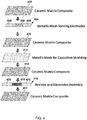
- FIG. 4 illustrates an example of layers 402, 404, 410, 412, 414, 416, and 422 of a ceramic matrix composite (CMC) body that form one of the RF sensors 102.
- the CMC body includes seven layers.
- CMCs comprise ceramic fibers embedded in a ceramic matrix.
- the matrix and fibers may comprise any ceramic material. Carbon, carbon fibers, and/or silicon carbide fibers may also be considered ceramic materials.
- Each of the fibers may be a bundle or a tow of ceramic tiles. The fibers in each bundle or tow may be braided or otherwise arranged.
- the fibers may comprise a material that is stable at temperatures above, for example, 1000 degrees Celsius.
- Examples of the fibers include fibers of alumina, mullite, silicon carbide, zirconia, and carbon.
- the ceramic matrix material include alumina, mullite, silicon carbide, zirconia, and carbon.
- Examples of the CMC include C/C, C/SiC, SiC/SiC, Al 2 O 3 /Al 2 O 3 , and Ox-Ox.
- the RF sensor 102 is described herein as being integral to the CMC body and comprising layers of CMC. However, depending the conditions that the RF sensor 102 will ultimately be subjected to, the RF sensor 102 may instead be integral to and include a type of composite that includes organic material such as a carbon fiber composite. For example, the RF sensor 102 may be included in a compressor section of the gas turbine engine, which will not be subjected to temperatures as hot as the turbine section of the gas turbine engine.
- a first layer 402 includes a layer of ceramic matrix composite.
- Ceramic matrix composites are a subgroup of composite materials as well as a subgroup of ceramics.
- a second layer 404 includes a section 406 of CMC and a metallic mesh 408 located on opposite sides of section 406 of CMC. Because the section 406 of CMC is a CMC, the section 406 includes at least one ceramic fiber and a ceramic matrix material in which the at least one ceramic fiber is embedded.
- the metallic mesh 408 located on opposite sides of section 406 of CMC forms electrodes of the capacitor C1 or C2.
- the section 406 of CMC and the CMC in the first layer 402 may have a relative permittivity (also known as dialectic constant) ⁇ r of, for example, 3 to 5.
- a third layer 410 includes a layer of ceramic matrix composite.
- a fourth layer 412 includes a metallic mesh for electrically shielding the capacitor C1 or C2 from the subsequent layers.
- a fifth layer 414 includes a layer of ceramic matrix composite.
- a sixth layer 416 includes a section 418 of CMC and a metallic mesh 420 located on opposite sides of the section 418 of CMC.
- the section 418 of CMC includes electrically conductive fibers, such as silicon carbide fibers.
- the electrically conductive fibers in the section 418 of CMC form a resistive element of the resistor of the resistor-capacitor circuit of the RF sensor 102.
- the metallic mesh 420 forms electrodes of the resistor R1 or R2.
- a seventh layer 422 includes a layer of ceramic matrix composite.
- the seven layers 402, 404, 410, 412, 414, 416, and 422 may be ordered as shown in FIG. 4 .
- the CMC body that forms the RF sensor 102 may include fewer, additional, or different layers than illustrated in FIG. 4 .
- the layers may be in any order suitable for the electrical elements of the RF sensor 102.
- the layers 402, 404, 410, 412, 414, 416, and 422 may be fully or partially created and then joined together.
- the layers may be formed during the formation of the CMC included in the CMC body.
- the layers may be formed by assembling a porous ceramic preform having layers, and then forming the porous ceramic preform into the ceramic matrix composite body by melt and/or vapor infiltration.
- Metal components, such as the metallic meshes 408, 412, and 420, may be included in the porous ceramic preform prior to infiltration and/or added after the CMC body (or one or more portions thereof) is formed.
- FIG. 5 is a cross-section of an example of the RF sensor 102.
- the capacitor end of the RF sensor 102 faces toward the rotor so that the tip 110 of the blade 104 passes by the capacitor end of the RF sensor 102 during operation of the gas turbine engine.
- a schematic element 502 representing a capacitor is shown in FIG. 5 merely to illustrate that there is a capacitance between the electrodes included in the second layer 404 and that the capacitance is influenced by the blade 104.
- FIG. 6 illustrates a cross-section of two of the RF sensors 102 that are interconnected to form the bridge-network circuit 304.
- Electrodes 602 are machined into a CMC body 604, which is the engine shroud in the illustrated example.
- the electrodes 602 may couple to cabling via one or more couplers (not shown).
- the RF sensors 102 are integral to the CMC body 604.
- the CMC body 604 may be a sensor block, which may be fastened to the engine shroud or any other component where the RF sensors 102 may sense the blades 104.
- the sensor block may be in the shape of a cylinder, a rectangular or square block, or any other three-dimensional shape.
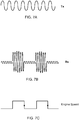
- FIGS. 7A-C illustrate examples of the voltage of various signals in the blade tip sensor 300 over a common time period.
- FIG. 7A illustrates the excitation signal.
- FIG. 7B illustrates a corresponding measurement signal R x on the line R x + or R x -.
- the voltage of the R x may increase as the blade 104 passes by the RF sensor 102.
- the two periods of time in which the magnitude of the Rx signal substantially increases indicates that two adjacent blades 104 passed by the RF sensor 102.
- the largest amplitude of the measurement signal indicates a value from which the tip clearance 206 may be calculated.
- the tip clearance 206 may be calculated from an averaged value of the amplitude over a period of time or from any other value derived from the measurement signal R x .
- FIG. 7C illustrates a binary signal derived from the measurement signal R x .
- the time between the trailing edges, for example, of the binary signal indicates an amount of time that passed between when the first blade 104 passed the RF sensor 102 and when the second blade 104 passed the RF sensor 102.
- the rotational speed of the rotor may be calculated from the amount time that passed and the angle between the two blades.
- FIGS. 8A and 8B illustrate differences in the measurement signal R x . depending on how worn the blade 104 is.
- FIG. 8A illustrates an example of a shape of the measurement signal R x if the blade 104 passes completely by the RF sensor 102 and the blade 104 is in its original shape.
- FIG. 8B illustrates an example of a shape of the measurement signal R x if the blade 104 passes completely by the RF sensor 102 and is worn.
- the blade 104 may be considered worn if the shape of the blade 104 is substantially different than the original shape of the blade 104 and/or if the difference in the shape of the blade 104 from the original exceeds a threshold.
- the processor 310 may detect the differences in the shapes by using digital signal processing techniques and/or artificial intelligence. For example, the processor 310 may use a neural network trained on past measurement signals and corresponding known wear conditions. Once trained, the neural network may predict whether the blade 104 is worn when provided the measurement signal R x .
- the blade tip sensor 300 may provide one or more improvements in real-time tip control.
- the gap between turbine blade tips and the turbine engine case is known to vary over the dissimilar temperature of the blades and the engine case. This gap allows either compressor air or turbine exhaust to "leak" past the blades with a resultant loss of energy generated by combustion.
- the blade tip sensor 300 has a resolution of one millimeter and an update rate of 10 milliseconds. In other examples, the blade tip sensor 300 may have a resolution of 0.001 inches. Alternatively or in addition, the blade tip sensor 300 may have any other resolution and/or update rate.
- the blade tip sensor 300 may detect wear in the blades or blade creep. Blade tips may leave the factory with a substantially rectangular geometry. After about 5000 hours of engine operation, the geometry may resemble a rounded butter-knife. Engine temperature, and abrasive or corrosive material in engine inlet air, may vary greatly depending on the engine operating environment and engine load.
- the blade tip sensor 300 may detect the loss of material from the blade tip and two centimeters inward, to a resolution of 1 percent (assuming 100 percent for a factory blade and zero percent for a missing blade). If one blade has a distinctive notch, maintenance software may identify which blade(s) have worn to the limit of a maintenance action (blade replacement). The wear can be implemented into the equipment health monitory system to indicate when maintenance is required.
- engine speed may be measured by, for example, timing the detection of the number of blades for one shaft resolution.
- the processor 310 may invert the time to report frequency and Revolutions per Minute (RPM).
- phase may be measured at the trailing edge of blades since less wear may be expected at the trailing edge of the blades.
- This phase may be linearly proportional to Torque (at stresses less than yield strength). Including temperature compensation may improve torque accuracy from 5 percent to 0.1 percent.
- the blade tip sensor 300 may detect a break in the shaft of the gas turbine engine. Detecting the speed and torque may be the basis of detecting different speeds at the front and rear of a shaft. The shaft break detection may be detected within 1 to 10 milliseconds of the break with 90 percent or better confidence.
- the blade tip sensor 300 may detect over-speed conditions. Detection of speeds exceeding 120 to 140 percent (with 1 percent resolution) enables fuel cut-off before the gas turbine engine self-destructs. The over-speed detection may be detected within 1 to 10 milliseconds of the over-speed condition, with a 90 percent or better confidence.
- the processor 310 may send a request to disable fuel delivery in response to detecting an over-speed condition.
- bearing wear may be measured as the differential blade gap opens up due to aging.
- the blade tip sensor 300 may have a lower cost than more complicated electronic systems such as microwave or optical speed measurement systems.
- the bridge-network circuit 304 may be integrated into the engine shroud 106 due to SiC-SiC, CMC-CMC, and other high temperature materials.
- the blade tip sensor 300 may eliminate and/or reduce inherent parasitic effects (capacitive and inductive) by sampling with multiple excitation frequencies. Arranging the RF sensors 102 in the bridge-network circuit 304 aids in accuracy and may provide reduced noise stability.
- the gas turbine engine may take a variety of forms in various embodiments.
- the gas turbine engine may be an axial flow engine.
- the gas turbine engine may have multiple spools and/or may be a centrifugal or mixed centrifugal/axial flow engine.
- the gas turbine engine may be a turboprop, a turbofan, or a turboshaft engine.
- the gas turbine engine may be an adaptive cycle and/or variable cycle engine. Other variations are also contemplated.
- the gas turbine engine may supply power to and/or provide propulsion of an aircraft.
- the aircraft may include a helicopter, an airplane, an unmanned space vehicle, a fixed wing vehicle, a variable wing vehicle, a rotary wing vehicle, an unmanned combat aerial vehicle, a tailless aircraft, a hover craft, and any other airborne and/or extraterrestrial (spacecraft) vehicle.
- the gas turbine engine may be utilized in a configuration unrelated to an aircraft such as, for example, an industrial application, an energy application, a power plant, a pumping set, a marine application (for example, for naval propulsion), a weapon system, a security system, a perimeter defense or security system.
- the phrases "at least one of ⁇ A>, ⁇ B>, ... and ⁇ N>” or “at least one of ⁇ A>, ⁇ B>, ... ⁇ N>, or combinations thereof or " ⁇ A>, ⁇ B>, ... and/or ⁇ N>” are defined by the Applicant in the broadest sense, superseding any other implied definitions hereinbefore or hereinafter unless expressly asserted by the Applicant to the contrary, to mean one or more elements selected from the group comprising A, B, ... and N. In other words, the phrases mean any combination of one or more of the elements A, B, ...
Landscapes
- Engineering & Computer Science (AREA)
- Mechanical Engineering (AREA)
- General Engineering & Computer Science (AREA)
- Physics & Mathematics (AREA)
- General Physics & Mathematics (AREA)
- Life Sciences & Earth Sciences (AREA)
- Biodiversity & Conservation Biology (AREA)
- Ecology (AREA)
- Environmental & Geological Engineering (AREA)
- Environmental Sciences (AREA)
- Health & Medical Sciences (AREA)
- Chemical & Material Sciences (AREA)
- Analytical Chemistry (AREA)
- Biochemistry (AREA)
- General Health & Medical Sciences (AREA)
- Immunology (AREA)
- Pathology (AREA)
- Measurement Of Length, Angles, Or The Like Using Electric Or Magnetic Means (AREA)
- Turbine Rotor Nozzle Sealing (AREA)
Abstract
Description
- This disclosure relates to sensors and, in particular, to blade tip sensors.
- Present blade tip sensors suffer from a variety of drawbacks, limitations, and disadvantages. Accordingly, there is a need for inventive systems, methods, components, and apparatuses described herein.
- In one aspect, there is provided a radio frequency sensor including a composite body including a plurality of ceramic fibers in a plurality of layers. The radio frequency sensor further includes a resistor-capacitor circuit embedded in the composite body. A portion of the composite body forms a dielectric of a capacitor of the resistor-capacitor circuit. The capacitor has a capacitance that depends on a distance between the capacitor and a blade of a rotor of a gas turbine engine.
- In some embodiments, the composite body includes a metallic mesh separating the capacitor and a resistor of the resistor-capacitor circuit.
- In some embodiments, a layer of the composite body includes a metallic mesh that is an electrode in the resistor-capacitor circuit.
- In some embodiments, the composite body includes a metallic mesh on opposite sides of a section of the ceramic fibers of one of the layers that is located between two other of the layers. The metallic mesh forms electrodes of the capacitor. The section of the ceramic fibers is part of a dielectric of the capacitor.
- In some embodiments, the composite body includes a metallic mesh on opposite sides of a section of electrically conductive fibers of one of the layers that is located between two other of the layers. The metallic mesh form electrodes of a resistor of the resistor-capacitor circuit. Further, the electrically conductive fibers form a resistive element of the resistor.
- In some embodiments, the composite body includes electrically conductive fibers.
- In some embodiments, the composite body includes a ceramic matrix composite body.
- In another aspect, there is provided a method to form a blade tip sensor. The method includes arranging a plurality of ceramic fibers in a plurality of layers to form a porous ceramic preform. The method further includes forming the porous ceramic preform into a ceramic matrix composite body by melt and/or vapor infiltration. At least one of the ceramic fibers is part of a capacitor of a bridge-network circuit embedded in the ceramic matrix composite body. The bridge-network circuit includes a first resistor-capacitor circuit on a first branch and a second resistor-capacitor circuit on a second branch. The capacitor is included in the first resistor-capacitor circuit or the second resistor-capacitor circuit. The capacitor has a capacitance that depends on a distance between the capacitor and a blade of a rotor of a gas turbine engine.
- In some embodiments, the method further includes including a metallic mesh for electromagnetic shielding in the porous ceramic preform before forming the porous ceramic preform into the ceramic matrix composite body.
- In some embodiments, the method further includes including a metallic mesh for an electrode in the porous ceramic preform before forming the porous ceramic preform into the ceramic matrix composite body.
- In some embodiments, the method further includes including a metallic mesh on opposite sides of a section of the ceramic fibers of one of the layers that is located between two other of the layers. After forming the porous ceramic preform into the ceramic matrix composite body, the metallic mesh forms electrodes of the capacitor, and the section of the ceramic fibers is part of a dielectric of the capacitor.
- In some embodiments, the method further includes including a metallic mesh on opposite sides of a section of electrically conductive fibers of one of the layers that is located between two other of the layers. After forming the porous ceramic preform into the ceramic matrix composite body, the metallic mesh form electrodes of a resistor in the first resistor-capacitor circuit or the second resistor-capacitor circuit, and the electrically conductive fibers form a resistive element of the resistor.
- In some embodiments, the electrically conductive fibers include silicon carbide fibers.
- In some embodiments, the ceramic matrix composite body includes a section of an engine shroud.
- In another aspect, there is provided a blade tip sensor including a bridge-network circuit including a first resistor-capacitor circuit on a first branch and a second resistor-capacitor circuit on a second branch. The bridge-network circuit is included in a composite body. Each of the first resistor-capacitor circuit and the second resistor-capacitor circuit includes a corresponding capacitor having a capacitance that depends on a distance between the corresponding capacitor and a blade of a rotor.
- The blade tip sensor may provide one or more improvements in real-time tip control.
- In some embodiments, the blade tip sensor includes a transceiver configured to generate and transmit an excitation signal at a plurality of frequencies to the bridge-network circuit.
- In some embodiments, the blade tip sensor further includes a processor configured to determine blade tip clearance from a capacitance derived from a measurement signal received from the bridge-network circuit.
- Determining tip clearance may enable maintaining concentricity. Maintaining concentricity may improve fuel efficiency and decrease maintenance issues.
- In some embodiments, the blade tip sensor includes a processor configured to detect wear on the blade from a measurement signal received from the bridge-network circuit.
- The wear can be implemented into an equipment health monitory system to indicate when maintenance is required.
- In some embodiments, the blade tip sensor includes a processor configured to determine engine speed from a measurement signal received from the bridge-network circuit.
- The processor may send a request to disable fuel delivery in response to detecting an over-speed condition.
- In some embodiments, the blade tip sensor further includes a processor configured to detect shaft break based on a measurement signal received from the bridge-network circuit.
- The blade tip sensor may have a lower cost than more complicated electronic systems such as microwave or optical speed measurement systems.
- The embodiments may be better understood with reference to the following drawings and description. The components in the figures are not necessarily to scale. Moreover, in the figures, like-referenced numerals designate corresponding parts throughout the different views.
-
FIG. 1 is a cross-sectional view of a gas turbine engine that includes RF sensors integrated into a ceramic matrix composite engine shroud; -
FIG. 2 is a cross-sectional view of the gas turbine engine taken in a plane parallel to the flow path; -
FIG. 3 illustrates a circuit diagram of a blade tip sensor; -
FIG. 4 illustrates an example of layers of a ceramic matrix composite body that form a RF sensor; -
FIG. 5 is a cross-section of an example of a RF sensor; -
FIG. 6 illustrates a cross-section of two RF sensors that are interconnected to form a bridge-network circuit; -
FIG. 7A illustrates the excitation signal; -
FIG. 7B illustrates a corresponding measurement signal; -
FIG. 7C illustrates a binary signal derived from the measurement signal; -
FIG. 8A illustrates an example of a shape of a measurement signal if a blade passes completely by a RF sensor and the blade is in its original shape; and -
FIG. 8B illustrates an example of a shape of a measurement signal if a blade passes completely by the RF sensor and is worn. - In one example, a radio frequency sensor is provided comprising a composite body and a resistor-capacitor circuit embedded in the composite body. The composite body may be, for example, a ceramic matrix composite (CMC) body such as a CMC engine shroud. A portion of the composite body forms a dielectric of a capacitor of the resistor-capacitor circuit, and the capacitor has a capacitance that depends on a distance between the capacitor and a blade of a rotor of gas turbine engine.
- In another example, a blade tip sensor is provided comprising a bridge-network circuit included in a composite body. The bridge-network circuit comprises a first resistor-capacitor circuit on a first branch and a second resistor-capacitor circuit on a second branch. Each of the first resistor-capacitor circuit and the second resistor-capacitor circuit includes a corresponding capacitor having a capacitance that depends on a distance between the corresponding capacitor and a blade of a rotor.
- In still another example, a method to form a blade tip sensor is provided. Ceramic fibers are arranged in in layers to form a porous ceramic preform. The ceramic preform is formed into a ceramic matrix composite body by melt and/or vapor infiltration. At least one of the ceramic fibers is part of a capacitor of a bridge-network circuit embedded in the ceramic matrix composite body. The bridge-network circuit comprises a first resistor-capacitor circuit on a first branch and a second resistor-capacitor circuit on a second branch. The capacitor is included in the first resistor-capacitor circuit or the second resistor-capacitor circuit. The capacitor has a capacitance that depends on a distance between the capacitor and a blade of a rotor of gas turbine engine.
-
FIG. 1 is a cross-sectional view of a gas turbine engine that includes radio frequency (RF)sensors 102 integrated into a ceramic matrix composite (CMC)engine shroud 106. TheRF sensors 102 are arranged at various locations around theCMC engine shroud 106. During operation of the gas turbine engine,blades 104 of arotor 108 may rotate so thattips 110 of theblades 104 pass theRF sensors 102. To help improve accuracy, 3 to 4 pairs of theRF sensors 102 may be located circumferentially around theCMC engine shroud 106. Such an arrangement enables detection of engine casing deflection and, together with a tip clearance control system, enables maintaining concentricity. Maintaining concentricity may improve fuel efficiency and decrease maintenance issues. - The cross-sectional view of the gas turbine engine shown in
FIG. 1 is of a cross-section taken in plane perpendicular to a flow path of a fluid that flows through therotor 108 and past theblades 104. In contrast,FIG. 2 is a cross-sectional view of the gas turbine engine taken in a plane parallel to the flow path. InFIG. 2 , theblade tip 110 of one of theblades 104 is shown in proximity to theCMC engine shroud 106 and, in particular, in proximity to one of theRF sensors 102. In the illustrated example, theCMC engine shroud 106 includes anengine shroud substrate 202 and anabradable substrate 204 located in theengine shroud substrate 202. Theabradable substrate 204 is positioned radially outward from theblade tip 110 and has an exposed surface facing theblade tip 110. A distance between theblade tip 110 and theabradable substrate 204 is referred to astip clearance 206 or blade tip clearance. One of theRF sensors 102 is shown embedded in theabradable substrate 204 inFIG. 2 . -
FIG. 3 illustrates a circuit diagram of ablade tip sensor 300 or blade tip sensor system, which includes two of theRF sensors 102 arranged in a bridge-network circuit 304 and anRF transceiver 302. Although not shown inFIG. 3 , the bridge-network circuit 304 is embedded in a ceramic matric composite body, such as theCMC engine shroud 106. - The
RF transceiver 302 may be located in a different location than the twoRF sensors 102. For example, theRF transceiver 302 may be located in a cooler location than theRF sensors 102. TheRF transceiver 302 may be any device configured to generate and transmit an excitation signal to nodes Vexc+ and Vexc- of the bridge-network circuit 304, and to receive measurement signals from nodes VD1 and VD2 of the bridge-network circuit 304. The excitation signal may have a predetermined frequency. The excitation signal may be sine wave, a sawtooth wave, a square wave, or any other shaped periodic signal. - In the example shown in
FIG. 3 , theRF transceiver 302 includes an RF transmitter-receiver integrated circuit 308 ("RF transceiver IC") and aClass C Amplifier 306. TheRF transceiver IC 308 is configured to generate and transmit the excitation signal over lines Tx+ and Tx- to the bridge-network circuit 304. The excitation signal is fed through theClass C amplifier 306 to drive the bridge-network circuit 304 at a relatively high power and relatively high frequency, and to naturally modulate a carrier frequency, such as 100 MHz. In other examples, theRF transceiver IC 308 includes a built-in Class C amplifier and theClass C amplifier 306 that is discrete from theRF transceiver IC 308 is not included in theRF transceiver 302. In still other examples, theRF transceiver 302 generates and transmits a non-truncated excitation signal and no Class C amplifier is included in theRF transceiver 302. TheRF transceiver IC 308 is configured to receive the measurement signals from the bridge-network circuit 304 over lines Rx+ and Rx-. TheRF transceiver IC 308 may include a DAC (digital to analog converter) that converts the received measurement signals into digital signals. An example of theRF transceiver IC 308 is a product from Analog Devices called the Integrated Dual RF Tx, Rx, and Observation Rx, model ADRV9009. Model ADRV9009 has a relatively wide frequency range, relatively wide bandwidth as a single chip radio. - In the illustrated example, a first one of the
RF sensors 102 includes a first resistor-capacitor circuit, and a second one of theRF sensors 102 includes a second resistor-capacitor circuit. The bridge-network circuit 304 includes the first resistor-capacitor circuit on a first branch and the second resistor-capacitor circuit on a second branch. The first resistor-capacitor circuit on the first branch includes a resistor R1 and a capacitor C1 connected in series. The second resistor-capacitor circuit on the second branch includes a resistor R2 and a capacitor C2 connected in series. Current I1 may flow through the first branch, and current I2 may flow through the second branch. The bridge-network circuit 304 in the illustrated example is in a half bridge configuration. The bridge-network circuit 304 may include any number of active and/or passive RF impedances. - In other words, the bridge-
network circuit 304 inFIG. 3 includes two active components that act as variable capacitance sensors (C1 and C2) and two fixed resistors (R1 and R2). The relationship between dielectric permittivity (ε), area (A), and separation (d) associated with capacitance is described by the equation:
- As indicated by this equation, the value of the capacitance sensor - in other words, the effective capacitance of the capacitor C1 or C2 - varies as the distance between the capacitor C1 or C2 and the
blade tip 110 increases or decreases. As a result, the capacitor C1 or C2 has a capacitance that depends on a distance between the capacitor C1 or C2 and theblade tip 110. Furthermore, the capacitance of the capacitor C1 or C2 is an indicator of the size of thetip clearance 206. To improve the performance of the capacitor C1 or C2 acting as a capacitance sensor, the capacitor C1 and C2 may be screened to attenuate effects of parasitic capacitance in integration with the engine. - Based on the high temperatures in the compressor and turbine sections of the gas turbine engine, each of the
RF sensors 102 may preferably include a capacitive sensor as compared to an inductive sensor. This is due to the material limitations associated with the Curie Temperatures of magnetic materials. In addition, because theblades 104 may comprise a non-metallic or a composite material, the capacitive effects may be easier to process with more accuracy. By integrating theRF sensors 102 into theengine shroud 106, theRF sensors 102 may be located strategically to capture passings of theblade 104 with a local maxima and minima of measured capacitances and to operate the bridge-network circuit 304 at a higher level of sensitivity than may be possible otherwise. - The
RF transceiver 302 may operate in a 100 to 300 MHz frequency band or any other suitable frequency band. For example, the driving signal may have a frequency of 100 MHz, 120 MHz, and/or any other frequency within the operable frequency band. The fixed resistances, R1 and R2 in theRF sensors 102 may be on the order of 100 ohms. The capacitor C1 or C2 in each of theRF sensors 102 may have a capacitance in a range of 1 to 20 pF. With such configuration, the bridge-network circuit 304 may be able generate differential voltages on the order of 0.4 to 1 Volts. With this level of sensitivity, theblade tip sensor 300 may detect relatively high levels of tip clearance and tip clearances down to a fraction of 1 mm. As thetip clearance 206 gets tighter during the tip clearance control operation, the variable capacitance associated with theblade tip 110 passing increases linearly in a predictable pattern. Because of this relationship, aprocessor 310, such as a digital signal processor, may correlate differential output voltage vs variable capacitance of the capacitors C1 and C2, and determine thetip clearance 206 from the measured capacitance. The capacitance associated with the tip clearance variation also may provide an indication of the shape and wear of theblades 104 of the compressor or the turbine. Accordingly, theprocessor 310 may determine the shape and/or wear of theblades 104 and/or thetip 110 of theblades 104. - Examples of the
processor 310 may include a general processor, a central processing unit, a microcontroller, an engine controller, an application specific integrated circuit (ASIC), a digital signal processor, a field programmable gate array (FPGA), a digital circuit, and/or an analog circuit. Theprocessor 310 may be one or more devices operable to execute logic. In some examples, the logic may include computer executable instructions or computer code embodied in memory that when executed by theprocessor 310, cause the processor to perform the features implemented by the logic. The computer code may include instructions executable with theprocessor 310. - In some examples, the
Class C Amplifier 306 may be compatible with a 75 MHz to 6 GHz carrier frequency of the Analog Devices ADRV9009 when the Analog Devices ADRV9009 is selected as theRF Transceiver IC 308. TheClass C Amplifier 306 may also comply with power limits imposed by the Federal Communications Commission (FCC), which limit radiated emissions to a 15 to 50 milliwatt limit. Selecting 100 MHz as the carrier frequency may provide sufficient resolution of theblade tip 110 and sufficient over-sampling capability in some configurations. In some examples, the excitation signal may be injected at multiple frequencies, such as 100 and 120 MHz. Signals at the multiple frequencies may be superimposed on the same input nodes, or time division multiplexing techniques may be implemented. Any combination of frequencies for the excitation signal may be selected as long as the as theRF Transceiver IC 308 has a high enough bandwidth to accurately decode the measurement signals. Using two frequencies that are close together, such as 100 and 120 MHz, for the excitation signal may be helpful. - The
processor 310 may perform signal processing on the measured signals VD1 and VD2. In one example, theprocessor 310 may include an Analog Devices Tiger-Shark 32-bit floating point Digital Signal Processing (DSP) integrated circuit. - Communication between the
processor 310 and other systems (not shown) may be performed over any communications network. Examples of the communications network may include ARINC-664 (AFDX, based on Ethernet), Bosch CAN bus, ARINC-429, and/or MIL-STD-1553B. The communications may be used for reporting blade clearance, speed, wear conditions, and/or any other information. The communications standard selected may be application specific. -
FIG. 4 illustrates an example oflayers RF sensors 102. In the illustrated example, the CMC body includes seven layers. - CMCs comprise ceramic fibers embedded in a ceramic matrix. The matrix and fibers may comprise any ceramic material. Carbon, carbon fibers, and/or silicon carbide fibers may also be considered ceramic materials. Each of the fibers may be a bundle or a tow of ceramic tiles. The fibers in each bundle or tow may be braided or otherwise arranged. The fibers may comprise a material that is stable at temperatures above, for example, 1000 degrees Celsius. Examples of the fibers include fibers of alumina, mullite, silicon carbide, zirconia, and carbon. Examples of the ceramic matrix material include alumina, mullite, silicon carbide, zirconia, and carbon. Examples of the CMC include C/C, C/SiC, SiC/SiC, Al2O3/Al2O3, and Ox-Ox.
- The
RF sensor 102 is described herein as being integral to the CMC body and comprising layers of CMC. However, depending the conditions that theRF sensor 102 will ultimately be subjected to, theRF sensor 102 may instead be integral to and include a type of composite that includes organic material such as a carbon fiber composite. For example, theRF sensor 102 may be included in a compressor section of the gas turbine engine, which will not be subjected to temperatures as hot as the turbine section of the gas turbine engine. - A
first layer 402 includes a layer of ceramic matrix composite. Ceramic matrix composites (CMCs) are a subgroup of composite materials as well as a subgroup of ceramics. - A
second layer 404 includes asection 406 of CMC and ametallic mesh 408 located on opposite sides ofsection 406 of CMC. Because thesection 406 of CMC is a CMC, thesection 406 includes at least one ceramic fiber and a ceramic matrix material in which the at least one ceramic fiber is embedded. Thesection 406 of CMC, as well as the CMC in thefirst layer 402, form a dielectric of the capacitor C1 or C2 of the resistor-capacitor circuit of theRF sensor 102. Themetallic mesh 408 located on opposite sides ofsection 406 of CMC forms electrodes of the capacitor C1 or C2. Thesection 406 of CMC and the CMC in thefirst layer 402 may have a relative permittivity (also known as dialectic constant) εr of, for example, 3 to 5. - A
third layer 410 includes a layer of ceramic matrix composite. Afourth layer 412 includes a metallic mesh for electrically shielding the capacitor C1 or C2 from the subsequent layers. Afifth layer 414 includes a layer of ceramic matrix composite. - A
sixth layer 416 includes asection 418 of CMC and ametallic mesh 420 located on opposite sides of thesection 418 of CMC. Thesection 418 of CMC includes electrically conductive fibers, such as silicon carbide fibers. The electrically conductive fibers in thesection 418 of CMC form a resistive element of the resistor of the resistor-capacitor circuit of theRF sensor 102. Themetallic mesh 420 forms electrodes of the resistor R1 or R2. - A
seventh layer 422 includes a layer of ceramic matrix composite. The sevenlayers FIG. 4 . Alternatively, the CMC body that forms theRF sensor 102 may include fewer, additional, or different layers than illustrated inFIG. 4 . The layers may be in any order suitable for the electrical elements of theRF sensor 102. - Two or more of the
layers metallic meshes -
FIG. 5 is a cross-section of an example of theRF sensor 102. The capacitor end of theRF sensor 102 faces toward the rotor so that thetip 110 of theblade 104 passes by the capacitor end of theRF sensor 102 during operation of the gas turbine engine. Aschematic element 502 representing a capacitor is shown inFIG. 5 merely to illustrate that there is a capacitance between the electrodes included in thesecond layer 404 and that the capacitance is influenced by theblade 104. -
FIG. 6 illustrates a cross-section of two of theRF sensors 102 that are interconnected to form the bridge-network circuit 304.Electrodes 602 are machined into aCMC body 604, which is the engine shroud in the illustrated example. Theelectrodes 602 may couple to cabling via one or more couplers (not shown). TheRF sensors 102 are integral to theCMC body 604. In other examples, theCMC body 604 may be a sensor block, which may be fastened to the engine shroud or any other component where theRF sensors 102 may sense theblades 104. The sensor block may be in the shape of a cylinder, a rectangular or square block, or any other three-dimensional shape. -
FIGS. 7A-C illustrate examples of the voltage of various signals in theblade tip sensor 300 over a common time period.FIG. 7A illustrates the excitation signal. -
FIG. 7B illustrates a corresponding measurement signal Rx on the line Rx+ or Rx-. The voltage of the Rx may increase as theblade 104 passes by theRF sensor 102. In the illustrated example, the two periods of time in which the magnitude of the Rx signal substantially increases indicates that twoadjacent blades 104 passed by theRF sensor 102. The largest amplitude of the measurement signal indicates a value from which thetip clearance 206 may be calculated. Alternatively or in addition, thetip clearance 206 may be calculated from an averaged value of the amplitude over a period of time or from any other value derived from the measurement signal Rx. -
FIG. 7C illustrates a binary signal derived from the measurement signal Rx. The time between the trailing edges, for example, of the binary signal indicates an amount of time that passed between when thefirst blade 104 passed theRF sensor 102 and when thesecond blade 104 passed theRF sensor 102. The rotational speed of the rotor may be calculated from the amount time that passed and the angle between the two blades. -
FIGS. 8A and 8B illustrate differences in the measurement signal Rx. depending on how worn theblade 104 is.FIG. 8A illustrates an example of a shape of the measurement signal Rx if theblade 104 passes completely by theRF sensor 102 and theblade 104 is in its original shape. In contrast,FIG. 8B illustrates an example of a shape of the measurement signal Rx if theblade 104 passes completely by theRF sensor 102 and is worn. Theblade 104 may be considered worn if the shape of theblade 104 is substantially different than the original shape of theblade 104 and/or if the difference in the shape of theblade 104 from the original exceeds a threshold. Theprocessor 310 may detect the differences in the shapes by using digital signal processing techniques and/or artificial intelligence. For example, theprocessor 310 may use a neural network trained on past measurement signals and corresponding known wear conditions. Once trained, the neural network may predict whether theblade 104 is worn when provided the measurement signal Rx. - The
blade tip sensor 300 may provide one or more improvements in real-time tip control. The gap between turbine blade tips and the turbine engine case is known to vary over the dissimilar temperature of the blades and the engine case. This gap allows either compressor air or turbine exhaust to "leak" past the blades with a resultant loss of energy generated by combustion. In some examples, theblade tip sensor 300 has a resolution of one millimeter and an update rate of 10 milliseconds. In other examples, theblade tip sensor 300 may have a resolution of 0.001 inches. Alternatively or in addition, theblade tip sensor 300 may have any other resolution and/or update rate. - As indicated above, the
blade tip sensor 300 may detect wear in the blades or blade creep. Blade tips may leave the factory with a substantially rectangular geometry. After about 5000 hours of engine operation, the geometry may resemble a rounded butter-knife. Engine temperature, and abrasive or corrosive material in engine inlet air, may vary greatly depending on the engine operating environment and engine load. Theblade tip sensor 300 may detect the loss of material from the blade tip and two centimeters inward, to a resolution of 1 percent (assuming 100 percent for a factory blade and zero percent for a missing blade). If one blade has a distinctive notch, maintenance software may identify which blade(s) have worn to the limit of a maintenance action (blade replacement). The wear can be implemented into the equipment health monitory system to indicate when maintenance is required. - Alternatively or in addition, engine speed may be measured by, for example, timing the detection of the number of blades for one shaft resolution. The
processor 310 may invert the time to report frequency and Revolutions per Minute (RPM). - The use of two blade tip sensors or a combination of the blade tip sensor and a different type of rotational sensor, one at the front and one at the rear of a shaft in the gas turbine engine, enable detection of speed signal phase changes. As explained above, phase may be measured at the trailing edge of blades since less wear may be expected at the trailing edge of the blades. This phase may be linearly proportional to Torque (at stresses less than yield strength). Including temperature compensation may improve torque accuracy from 5 percent to 0.1 percent.
- The
blade tip sensor 300 may detect a break in the shaft of the gas turbine engine. Detecting the speed and torque may be the basis of detecting different speeds at the front and rear of a shaft. The shaft break detection may be detected within 1 to 10 milliseconds of the break with 90 percent or better confidence. - The
blade tip sensor 300 may detect over-speed conditions. Detection of speeds exceeding 120 to 140 percent (with 1 percent resolution) enables fuel cut-off before the gas turbine engine self-destructs. The over-speed detection may be detected within 1 to 10 milliseconds of the over-speed condition, with a 90 percent or better confidence. Theprocessor 310 may send a request to disable fuel delivery in response to detecting an over-speed condition. - If the
RF sensors 102 are located circumferentially around the engine shroud, bearing wear may be measured as the differential blade gap opens up due to aging. - The
blade tip sensor 300 may have a lower cost than more complicated electronic systems such as microwave or optical speed measurement systems. The bridge-network circuit 304 may be integrated into theengine shroud 106 due to SiC-SiC, CMC-CMC, and other high temperature materials. - The
blade tip sensor 300 may eliminate and/or reduce inherent parasitic effects (capacitive and inductive) by sampling with multiple excitation frequencies. Arranging theRF sensors 102 in the bridge-network circuit 304 aids in accuracy and may provide reduced noise stability. - The gas turbine engine may take a variety of forms in various embodiments. For example, the gas turbine engine may be an axial flow engine. The gas turbine engine may have multiple spools and/or may be a centrifugal or mixed centrifugal/axial flow engine. In some forms, the gas turbine engine may be a turboprop, a turbofan, or a turboshaft engine. Furthermore, the gas turbine engine may be an adaptive cycle and/or variable cycle engine. Other variations are also contemplated.
- The gas turbine engine may supply power to and/or provide propulsion of an aircraft. Examples of the aircraft may include a helicopter, an airplane, an unmanned space vehicle, a fixed wing vehicle, a variable wing vehicle, a rotary wing vehicle, an unmanned combat aerial vehicle, a tailless aircraft, a hover craft, and any other airborne and/or extraterrestrial (spacecraft) vehicle. Alternatively or in addition, the gas turbine engine may be utilized in a configuration unrelated to an aircraft such as, for example, an industrial application, an energy application, a power plant, a pumping set, a marine application (for example, for naval propulsion), a weapon system, a security system, a perimeter defense or security system.
- To clarify the use of and to hereby provide notice to the public, the phrases "at least one of <A>, <B>, ... and <N>" or "at least one of <A>, <B>, ... <N>, or combinations thereof or "<A>, <B>, ... and/or <N>" are defined by the Applicant in the broadest sense, superseding any other implied definitions hereinbefore or hereinafter unless expressly asserted by the Applicant to the contrary, to mean one or more elements selected from the group comprising A, B, ... and N. In other words, the phrases mean any combination of one or more of the elements A, B, ... or N including any one element alone or the one element in combination with one or more of the other elements which may also include, in combination, additional elements not listed. Unless otherwise indicated or the context suggests otherwise, as used herein, "a" or "an" means "at least one" or "one or more."
- While various embodiments have been described, it will be apparent to those of ordinary skill in the art that many more embodiments and implementations are possible. Accordingly, the embodiments described herein are examples, not the only possible embodiments and implementations.
Claims (15)
- A radio frequency sensor (102) comprising:a composite body (106) comprising a plurality of ceramic fibers in a plurality of layers (402, 404, 410, 412, 414, 416, 422); anda resistor-capacitor circuit embedded in the composite body (106), wherein a portion of the composite body (106) forms a dielectric of a capacitor (C1, C2) of the resistor-capacitor circuit, and the capacitor (C1, C2) has a capacitance that depends on a distance (206) between the capacitor (C1, C2) and a blade (104) of a rotor (108) of a gas turbine engine.
- The radio frequency sensor (102) of claim 1, wherein the composite body (106) comprises a metallic mesh (412) separating the capacitor (C1, C2) and a resistor (R1, R2) of the resistor-capacitor circuit.
- The radio frequency sensor (102) of claim 1 or 2, wherein a layer (404, 416) of the composite body (106) comprises a metallic mesh (408, 420) that is an electrode in the resistor-capacitor circuit.
- The radio frequency sensor (102) of claim 1 or 2, wherein the composite body (106) includes a metallic mesh (408) on opposite sides of a section (406) of the ceramic fibers of one of the layers (404) that is located between two other of the layers (402, 410), wherein the metallic mesh (408) forms electrodes of the capacitor (C1, C2), and the section (406) of the ceramic fibers is part of a dielectric of the capacitor (C1, C2).
- The radio frequency sensor (102) of claim 1 or 2, wherein the composite body (106) includes a metallic mesh (420) on opposite sides of a section (418) of electrically conductive fibers of one of the layers (416) that is located between two other of the layers (414, 422), wherein the metallic mesh (420) forms electrodes of a resistor (R1, R2) of the resistor-capacitor circuit, and wherein the electrically conductive fibers form a resistive element of the resistor (R1, R2).
- The radio frequency sensor (102) of any one of claims 1 to 5, wherein the composite body (106) includes electrically conductive fibers.
- The radio frequency sensor (102) of claim 6, wherein the electrically conductive fibers comprise silicon carbide fibers.
- The radio frequency sensor (102) of any one of claims 1 to 7, wherein the composite body (106) comprises a ceramic matrix composite body.
- A method to form a blade tip sensor (300), the method comprising:arranging a plurality of ceramic fibers in a plurality of layers (402, 404, 410, 412, 414, 416, 422) to form a porous ceramic preform; andforming the porous ceramic preform into a ceramic matrix composite body by melt and/or vapor infiltration, wherein at least one of the ceramic fibers is part of a capacitor (C1, C2) of a bridge-network circuit (304) embedded in the ceramic matrix composite body, the bridge-network circuit (304) comprises a first resistor-capacitor circuit on a first branch and a second resistor-capacitor circuit on a second branch, and wherein the capacitor (C1, C2) is included in the first resistor-capacitor circuit or the second resistor-capacitor circuit, and the capacitor (C1, C2) has a capacitance that depends on a distance (206) between the capacitor (C1, C2) and a blade (104) of a rotor (108) of a gas turbine engine.
- The method of claim 9 further comprising including a metallic mesh (412) for electromagnetic shielding in the porous ceramic preform before forming the porous ceramic preform into the ceramic matrix composite body.
- The method of claim 9 or 10 further comprising including a metallic mesh (408, 420) for an electrode in the porous ceramic preform before forming the porous ceramic preform into the ceramic matrix composite body.
- The method of claim 9 or 10 further comprising including a metallic mesh (408) on opposite sides of a section (406) of the ceramic fibers of one of the layers (404) that is located between two other of the layers (402, 410), wherein after forming the porous ceramic preform into the ceramic matrix composite body, the metallic mesh (408) forms electrodes of the capacitor (C1, C2), and the section (406) of the ceramic fibers is part of a dielectric of the capacitor (C1, C2).
- The method of claim 9 or 10 further comprising including a metallic mesh (420) on opposite sides of a section (418) of electrically conductive fibers of one of the layers (416) that is located between two other of the layers (414, 422), wherein after forming the porous ceramic preform into the ceramic matrix composite body, the metallic mesh (420) form electrodes of a resistor (R1, R2) in the first resistor-capacitor circuit or the second resistor-capacitor circuit, and the electrically conductive fibers form a resistive element of the resistor (R1, R2).
- The method of claim 13, wherein the electrically conductive fibers comprise silicon carbide fibers.
- The method of any one of claims 9 to 14, wherein the ceramic matrix composite body comprises a section of an engine shroud (106).
Applications Claiming Priority (2)
| Application Number | Priority Date | Filing Date | Title |
|---|---|---|---|
| US201862769369P | 2018-11-19 | 2018-11-19 | |
| US16/373,563 US11143054B2 (en) | 2018-11-19 | 2019-04-02 | Tip clearance radio frequency sensor |
Publications (2)
| Publication Number | Publication Date |
|---|---|
| EP3653840A1 true EP3653840A1 (en) | 2020-05-20 |
| EP3653840B1 EP3653840B1 (en) | 2024-10-09 |
Family
ID=68296220
Family Applications (1)
| Application Number | Title | Priority Date | Filing Date |
|---|---|---|---|
| EP19204272.9A Active EP3653840B1 (en) | 2018-11-19 | 2019-10-21 | Tip clearance sensor |
Country Status (3)
| Country | Link |
|---|---|
| US (1) | US11143054B2 (en) |
| EP (1) | EP3653840B1 (en) |
| CA (1) | CA3056622A1 (en) |
Cited By (2)
| Publication number | Priority date | Publication date | Assignee | Title |
|---|---|---|---|---|
| FR3116228A1 (en) * | 2020-11-17 | 2022-05-20 | Safran Aircraft Engines | COMPOSITE PART, PARTICULARLY FOR AN AIRCRAFT TURBOMACHINE |
| FR3116229A1 (en) * | 2020-11-17 | 2022-05-20 | Safran Aircraft Engines | COMPOSITE PART, PARTICULARLY FOR AN AIRCRAFT TURBOMACHINE |
Families Citing this family (3)
| Publication number | Priority date | Publication date | Assignee | Title |
|---|---|---|---|---|
| US11002637B2 (en) * | 2018-11-30 | 2021-05-11 | Raytheon Technologies Corporation | Embedded wireless and passive sensor |
| CN115510383A (en) * | 2021-06-04 | 2022-12-23 | 苏州蛟视智能科技有限公司 | A Method of Constructing Sparse Measurement Matrix |
| CN120741883B (en) * | 2025-09-02 | 2025-11-18 | 四川新川航空仪器有限责任公司 | Rotor rotation speed signal processor with dual-mode criterion |
Citations (5)
| Publication number | Priority date | Publication date | Assignee | Title |
|---|---|---|---|---|
| US4818948A (en) * | 1986-08-05 | 1989-04-04 | Pratt & Whitney Canada Inc. | Capacitive bridge-type probe for measuring blade tip clearance |
| GB2314631A (en) * | 1996-06-26 | 1998-01-07 | Philips Electronics Nv | Composite capacitive sensor device |
| EP1314957A2 (en) * | 2001-11-16 | 2003-05-28 | General Electric Company | Method and apparatus for measuring turbine blade tip clearance |
| EP1918679A2 (en) * | 2006-10-31 | 2008-05-07 | Rolls-Royce plc | A sensor |
| EP2551451A1 (en) * | 2011-07-28 | 2013-01-30 | Ansaldo Energia S.p.A. | A gas turbine electric power plant and a method for operating this plant |
Family Cites Families (13)
| Publication number | Priority date | Publication date | Assignee | Title |
|---|---|---|---|---|
| GB2071852A (en) | 1980-03-12 | 1981-09-23 | Rolls Royce | Capacitance frequency modulation probe for blade tip clearance measurement |
| DE3433351C1 (en) | 1984-09-11 | 1986-01-02 | MTU Motoren- und Turbinen-Union München GmbH, 8000 München | Capacitive measuring system for measuring the distance between two parts that are movable relative to each other |
| US7618712B2 (en) | 2002-09-23 | 2009-11-17 | Siemens Energy, Inc. | Apparatus and method of detecting wear in an abradable coating system |
| US7270890B2 (en) | 2002-09-23 | 2007-09-18 | Siemens Power Generation, Inc. | Wear monitoring system with embedded conductors |
| US7455495B2 (en) | 2005-08-16 | 2008-11-25 | United Technologies Corporation | Systems and methods for monitoring thermal growth and controlling clearances, and maintaining health of turbo machinery applications |
| US20100079136A1 (en) | 2008-09-29 | 2010-04-01 | Rosemount Aerospace Inc. | Blade tip clearance measurement sensor and method for gas turbine engines |
| US8941395B2 (en) * | 2010-04-27 | 2015-01-27 | 3M Innovative Properties Company | Integrated passive circuit elements for sensing devices |
| EP2570766B1 (en) | 2011-09-16 | 2014-03-19 | Meggitt SA | Device and method for monitoring rotor blades of a turbine |
| US9709376B2 (en) * | 2014-05-12 | 2017-07-18 | The University Of Akron | High sensitivity inductive sensor for measuring blade tip clearance |
| US20170059159A1 (en) * | 2015-08-25 | 2017-03-02 | Rolls-Royce Corporation | Cmc combustor shell with integral chutes |
| CA2939288A1 (en) * | 2015-08-28 | 2017-02-28 | Rolls-Royce High Temperature Composites, Inc. | Ceramic matrix composite including silicon carbide fibers in a ceramic matrix comprising a max phase compound |
| ITUB20160851A1 (en) * | 2016-02-18 | 2017-08-18 | Torino Politecnico | SYSTEM FOR DISINFECTION OF AGRICULTURAL SOIL |
| EP3241815B1 (en) * | 2016-05-02 | 2019-11-13 | Rolls-Royce High Temperature Composites Inc | Reducing surface nodules in melt-infiltrated ceramic matrix composites |
-
2019
- 2019-04-02 US US16/373,563 patent/US11143054B2/en active Active
- 2019-09-25 CA CA3056622A patent/CA3056622A1/en active Pending
- 2019-10-21 EP EP19204272.9A patent/EP3653840B1/en active Active
Patent Citations (5)
| Publication number | Priority date | Publication date | Assignee | Title |
|---|---|---|---|---|
| US4818948A (en) * | 1986-08-05 | 1989-04-04 | Pratt & Whitney Canada Inc. | Capacitive bridge-type probe for measuring blade tip clearance |
| GB2314631A (en) * | 1996-06-26 | 1998-01-07 | Philips Electronics Nv | Composite capacitive sensor device |
| EP1314957A2 (en) * | 2001-11-16 | 2003-05-28 | General Electric Company | Method and apparatus for measuring turbine blade tip clearance |
| EP1918679A2 (en) * | 2006-10-31 | 2008-05-07 | Rolls-Royce plc | A sensor |
| EP2551451A1 (en) * | 2011-07-28 | 2013-01-30 | Ansaldo Energia S.p.A. | A gas turbine electric power plant and a method for operating this plant |
Cited By (4)
| Publication number | Priority date | Publication date | Assignee | Title |
|---|---|---|---|---|
| FR3116228A1 (en) * | 2020-11-17 | 2022-05-20 | Safran Aircraft Engines | COMPOSITE PART, PARTICULARLY FOR AN AIRCRAFT TURBOMACHINE |
| FR3116229A1 (en) * | 2020-11-17 | 2022-05-20 | Safran Aircraft Engines | COMPOSITE PART, PARTICULARLY FOR AN AIRCRAFT TURBOMACHINE |
| WO2022106780A1 (en) | 2020-11-17 | 2022-05-27 | Safran Aircraft Engines | Composite part, in particular for an aircraft turbine engine |
| US12098652B2 (en) | 2020-11-17 | 2024-09-24 | Safran Aircraft Engines | Composite part, in particular for an aircraft turbine engine |
Also Published As
| Publication number | Publication date |
|---|---|
| US20200157967A1 (en) | 2020-05-21 |
| CA3056622A1 (en) | 2020-05-19 |
| US11143054B2 (en) | 2021-10-12 |
| EP3653840B1 (en) | 2024-10-09 |
Similar Documents
| Publication | Publication Date | Title |
|---|---|---|
| EP3653840B1 (en) | Tip clearance sensor | |
| US11145960B2 (en) | Tip clearance sensor system with an integral patch antenna array | |
| EP4039584B1 (en) | Propeller blade angle feedback arrangement and method | |
| US10838053B2 (en) | System and method of measuring blade clearance in a turbine engine | |
| KR101809162B1 (en) | Self-powered sensing and transmitting device and method of fabricating the same | |
| EP3712057B1 (en) | Blade angle position feedback system with extended markers | |
| US9909443B2 (en) | Passive wireless sensors for turbomachines and method of operating the same | |
| EP4016088B1 (en) | Surface acoustic wave sensors for air data probes | |
| CN103620355A (en) | Device and method for measuring blade tip passage times in a turbomachine | |
| US9986312B2 (en) | Passive wireless sensors for turbomachines and method of operating the same | |
| EP1918679B1 (en) | Rotor assembly with a sensor for determining movement of the rotor. | |
| US20130298686A1 (en) | Device and method for monitoring a rotor | |
| US20190323818A1 (en) | Self-calibrating sensor for simultaneous measurement of rub depth and running clearance in a jet engine | |
| EP3896461A1 (en) | Hybrid speed sensing system | |
| CN113196023B (en) | Turbomachine with SAW or BAW device, measurement arrangement and method of installation | |
| US20260139607A1 (en) | Acoustic wave sensor system for a propulsion system | |
| Andronenko et al. | The use of microelectromechanical systems for surge detection in gas turbine engines | |
| US12024300B2 (en) | Method and system for ice detection | |
| EP2518275B1 (en) | Moisture monitoring system for gas turbine engines | |
| Sheard et al. | Gap Measurement Device | |
| Transducer | The vital role of sensors in aircraft engine monitoring and control | |
| Balazic et al. | Accuracies of digital engine monitoring proven by performance |
Legal Events
| Date | Code | Title | Description |
|---|---|---|---|
| PUAI | Public reference made under article 153(3) epc to a published international application that has entered the european phase |
Free format text: ORIGINAL CODE: 0009012 |
|
| STAA | Information on the status of an ep patent application or granted ep patent |
Free format text: STATUS: THE APPLICATION HAS BEEN PUBLISHED |
|
| AK | Designated contracting states |
Kind code of ref document: A1 Designated state(s): AL AT BE BG CH CY CZ DE DK EE ES FI FR GB GR HR HU IE IS IT LI LT LU LV MC MK MT NL NO PL PT RO RS SE SI SK SM TR |
|
| AX | Request for extension of the european patent |
Extension state: BA ME |
|
| STAA | Information on the status of an ep patent application or granted ep patent |
Free format text: STATUS: REQUEST FOR EXAMINATION WAS MADE |
|
| STAA | Information on the status of an ep patent application or granted ep patent |
Free format text: STATUS: EXAMINATION IS IN PROGRESS |
|
| 17P | Request for examination filed |
Effective date: 20201111 |
|
| RBV | Designated contracting states (corrected) |
Designated state(s): AL AT BE BG CH CY CZ DE DK EE ES FI FR GB GR HR HU IE IS IT LI LT LU LV MC MK MT NL NO PL PT RO RS SE SI SK SM TR |
|
| 17Q | First examination report despatched |
Effective date: 20201215 |
|
| GRAP | Despatch of communication of intention to grant a patent |
Free format text: ORIGINAL CODE: EPIDOSNIGR1 |
|
| STAA | Information on the status of an ep patent application or granted ep patent |
Free format text: STATUS: GRANT OF PATENT IS INTENDED |
|
| INTG | Intention to grant announced |
Effective date: 20240611 |
|
| GRAJ | Information related to disapproval of communication of intention to grant by the applicant or resumption of examination proceedings by the epo deleted |
Free format text: ORIGINAL CODE: EPIDOSDIGR1 |
|
| STAA | Information on the status of an ep patent application or granted ep patent |
Free format text: STATUS: EXAMINATION IS IN PROGRESS |
|
| GRAP | Despatch of communication of intention to grant a patent |
Free format text: ORIGINAL CODE: EPIDOSNIGR1 |
|
| P01 | Opt-out of the competence of the unified patent court (upc) registered |
Free format text: CASE NUMBER: APP_42280/2024 Effective date: 20240717 |
|
| STAA | Information on the status of an ep patent application or granted ep patent |
Free format text: STATUS: GRANT OF PATENT IS INTENDED |
|
| GRAS | Grant fee paid |
Free format text: ORIGINAL CODE: EPIDOSNIGR3 |
|
| INTC | Intention to grant announced (deleted) | ||
| GRAA | (expected) grant |
Free format text: ORIGINAL CODE: 0009210 |
|
| STAA | Information on the status of an ep patent application or granted ep patent |
Free format text: STATUS: THE PATENT HAS BEEN GRANTED |
|
| INTG | Intention to grant announced |
Effective date: 20240829 |
|
| AK | Designated contracting states |
Kind code of ref document: B1 Designated state(s): AL AT BE BG CH CY CZ DE DK EE ES FI FR GB GR HR HU IE IS IT LI LT LU LV MC MK MT NL NO PL PT RO RS SE SI SK SM TR |
|
| REG | Reference to a national code |
Ref country code: CH Ref legal event code: EP |
|
| REG | Reference to a national code |
Ref country code: DE Ref legal event code: R096 Ref document number: 602019059969 Country of ref document: DE |
|
| REG | Reference to a national code |
Ref country code: IE Ref legal event code: FG4D |
|
| REG | Reference to a national code |
Ref country code: LT Ref legal event code: MG9D |
|
| REG | Reference to a national code |
Ref country code: NL Ref legal event code: MP Effective date: 20241009 |
|
| REG | Reference to a national code |
Ref country code: AT Ref legal event code: MK05 Ref document number: 1730793 Country of ref document: AT Kind code of ref document: T Effective date: 20241009 |
|
| PG25 | Lapsed in a contracting state [announced via postgrant information from national office to epo] |
Ref country code: NL Free format text: LAPSE BECAUSE OF FAILURE TO SUBMIT A TRANSLATION OF THE DESCRIPTION OR TO PAY THE FEE WITHIN THE PRESCRIBED TIME-LIMIT Effective date: 20241009 |
|
| PG25 | Lapsed in a contracting state [announced via postgrant information from national office to epo] |
Ref country code: NL Free format text: LAPSE BECAUSE OF FAILURE TO SUBMIT A TRANSLATION OF THE DESCRIPTION OR TO PAY THE FEE WITHIN THE PRESCRIBED TIME-LIMIT Effective date: 20241009 |
|
| PG25 | Lapsed in a contracting state [announced via postgrant information from national office to epo] |
Ref country code: PT Free format text: LAPSE BECAUSE OF FAILURE TO SUBMIT A TRANSLATION OF THE DESCRIPTION OR TO PAY THE FEE WITHIN THE PRESCRIBED TIME-LIMIT Effective date: 20250210 Ref country code: HR Free format text: LAPSE BECAUSE OF FAILURE TO SUBMIT A TRANSLATION OF THE DESCRIPTION OR TO PAY THE FEE WITHIN THE PRESCRIBED TIME-LIMIT Effective date: 20241009 Ref country code: IS Free format text: LAPSE BECAUSE OF FAILURE TO SUBMIT A TRANSLATION OF THE DESCRIPTION OR TO PAY THE FEE WITHIN THE PRESCRIBED TIME-LIMIT Effective date: 20250209 |
|
| PG25 | Lapsed in a contracting state [announced via postgrant information from national office to epo] |
Ref country code: FI Free format text: LAPSE BECAUSE OF FAILURE TO SUBMIT A TRANSLATION OF THE DESCRIPTION OR TO PAY THE FEE WITHIN THE PRESCRIBED TIME-LIMIT Effective date: 20241009 |
|
| PG25 | Lapsed in a contracting state [announced via postgrant information from national office to epo] |
Ref country code: BG Free format text: LAPSE BECAUSE OF FAILURE TO SUBMIT A TRANSLATION OF THE DESCRIPTION OR TO PAY THE FEE WITHIN THE PRESCRIBED TIME-LIMIT Effective date: 20241009 |
|
| PG25 | Lapsed in a contracting state [announced via postgrant information from national office to epo] |
Ref country code: ES Free format text: LAPSE BECAUSE OF FAILURE TO SUBMIT A TRANSLATION OF THE DESCRIPTION OR TO PAY THE FEE WITHIN THE PRESCRIBED TIME-LIMIT Effective date: 20241009 |
|
| PG25 | Lapsed in a contracting state [announced via postgrant information from national office to epo] |
Ref country code: NO Free format text: LAPSE BECAUSE OF FAILURE TO SUBMIT A TRANSLATION OF THE DESCRIPTION OR TO PAY THE FEE WITHIN THE PRESCRIBED TIME-LIMIT Effective date: 20250109 |
|
| PG25 | Lapsed in a contracting state [announced via postgrant information from national office to epo] |
Ref country code: GR Free format text: LAPSE BECAUSE OF FAILURE TO SUBMIT A TRANSLATION OF THE DESCRIPTION OR TO PAY THE FEE WITHIN THE PRESCRIBED TIME-LIMIT Effective date: 20250110 Ref country code: LV Free format text: LAPSE BECAUSE OF FAILURE TO SUBMIT A TRANSLATION OF THE DESCRIPTION OR TO PAY THE FEE WITHIN THE PRESCRIBED TIME-LIMIT Effective date: 20241009 Ref country code: AT Free format text: LAPSE BECAUSE OF FAILURE TO SUBMIT A TRANSLATION OF THE DESCRIPTION OR TO PAY THE FEE WITHIN THE PRESCRIBED TIME-LIMIT Effective date: 20241009 |
|
| PG25 | Lapsed in a contracting state [announced via postgrant information from national office to epo] |
Ref country code: PL Free format text: LAPSE BECAUSE OF FAILURE TO SUBMIT A TRANSLATION OF THE DESCRIPTION OR TO PAY THE FEE WITHIN THE PRESCRIBED TIME-LIMIT Effective date: 20241009 |
|
| PG25 | Lapsed in a contracting state [announced via postgrant information from national office to epo] |
Ref country code: RS Free format text: LAPSE BECAUSE OF FAILURE TO SUBMIT A TRANSLATION OF THE DESCRIPTION OR TO PAY THE FEE WITHIN THE PRESCRIBED TIME-LIMIT Effective date: 20250109 |
|
| REG | Reference to a national code |
Ref country code: DE Ref legal event code: R119 Ref document number: 602019059969 Country of ref document: DE |
|
| REG | Reference to a national code |
Ref country code: CH Ref legal event code: PL |
|
| PG25 | Lapsed in a contracting state [announced via postgrant information from national office to epo] |
Ref country code: SM Free format text: LAPSE BECAUSE OF FAILURE TO SUBMIT A TRANSLATION OF THE DESCRIPTION OR TO PAY THE FEE WITHIN THE PRESCRIBED TIME-LIMIT Effective date: 20241009 |
|
| PG25 | Lapsed in a contracting state [announced via postgrant information from national office to epo] |
Ref country code: MC Free format text: LAPSE BECAUSE OF FAILURE TO SUBMIT A TRANSLATION OF THE DESCRIPTION OR TO PAY THE FEE WITHIN THE PRESCRIBED TIME-LIMIT Effective date: 20241009 |
|
| PG25 | Lapsed in a contracting state [announced via postgrant information from national office to epo] |
Ref country code: DE Free format text: LAPSE BECAUSE OF NON-PAYMENT OF DUE FEES Effective date: 20250501 |
|
| PG25 | Lapsed in a contracting state [announced via postgrant information from national office to epo] |
Ref country code: DK Free format text: LAPSE BECAUSE OF FAILURE TO SUBMIT A TRANSLATION OF THE DESCRIPTION OR TO PAY THE FEE WITHIN THE PRESCRIBED TIME-LIMIT Effective date: 20241009 |
|
| PG25 | Lapsed in a contracting state [announced via postgrant information from national office to epo] |
Ref country code: LU Free format text: LAPSE BECAUSE OF NON-PAYMENT OF DUE FEES Effective date: 20241021 Ref country code: BE Free format text: LAPSE BECAUSE OF NON-PAYMENT OF DUE FEES Effective date: 20241031 |
|
| PG25 | Lapsed in a contracting state [announced via postgrant information from national office to epo] |
Ref country code: EE Free format text: LAPSE BECAUSE OF FAILURE TO SUBMIT A TRANSLATION OF THE DESCRIPTION OR TO PAY THE FEE WITHIN THE PRESCRIBED TIME-LIMIT Effective date: 20241009 |
|
| PG25 | Lapsed in a contracting state [announced via postgrant information from national office to epo] |
Ref country code: CH Free format text: LAPSE BECAUSE OF NON-PAYMENT OF DUE FEES Effective date: 20241031 |
|
| PG25 | Lapsed in a contracting state [announced via postgrant information from national office to epo] |
Ref country code: RO Free format text: LAPSE BECAUSE OF FAILURE TO SUBMIT A TRANSLATION OF THE DESCRIPTION OR TO PAY THE FEE WITHIN THE PRESCRIBED TIME-LIMIT Effective date: 20241009 |
|
| PG25 | Lapsed in a contracting state [announced via postgrant information from national office to epo] |
Ref country code: SK Free format text: LAPSE BECAUSE OF FAILURE TO SUBMIT A TRANSLATION OF THE DESCRIPTION OR TO PAY THE FEE WITHIN THE PRESCRIBED TIME-LIMIT Effective date: 20241009 |
|
| PG25 | Lapsed in a contracting state [announced via postgrant information from national office to epo] |
Ref country code: CZ Free format text: LAPSE BECAUSE OF FAILURE TO SUBMIT A TRANSLATION OF THE DESCRIPTION OR TO PAY THE FEE WITHIN THE PRESCRIBED TIME-LIMIT Effective date: 20241009 |
|
| PG25 | Lapsed in a contracting state [announced via postgrant information from national office to epo] |
Ref country code: IT Free format text: LAPSE BECAUSE OF FAILURE TO SUBMIT A TRANSLATION OF THE DESCRIPTION OR TO PAY THE FEE WITHIN THE PRESCRIBED TIME-LIMIT Effective date: 20241009 |
|
| REG | Reference to a national code |
Ref country code: BE Ref legal event code: MM Effective date: 20241031 |
|
| PLBE | No opposition filed within time limit |
Free format text: ORIGINAL CODE: 0009261 |
|
| STAA | Information on the status of an ep patent application or granted ep patent |
Free format text: STATUS: NO OPPOSITION FILED WITHIN TIME LIMIT |
|
| PG25 | Lapsed in a contracting state [announced via postgrant information from national office to epo] |
Ref country code: SE Free format text: LAPSE BECAUSE OF FAILURE TO SUBMIT A TRANSLATION OF THE DESCRIPTION OR TO PAY THE FEE WITHIN THE PRESCRIBED TIME-LIMIT Effective date: 20241009 |
|
| 26N | No opposition filed |
Effective date: 20250710 |
|
| GBPC | Gb: european patent ceased through non-payment of renewal fee |
Effective date: 20250109 |
|
| PG25 | Lapsed in a contracting state [announced via postgrant information from national office to epo] |
Ref country code: GB Free format text: LAPSE BECAUSE OF NON-PAYMENT OF DUE FEES Effective date: 20250109 |
|
| PG25 | Lapsed in a contracting state [announced via postgrant information from national office to epo] |
Ref country code: IE Free format text: LAPSE BECAUSE OF NON-PAYMENT OF DUE FEES Effective date: 20241021 |
|
| PGFP | Annual fee paid to national office [announced via postgrant information from national office to epo] |
Ref country code: FR Payment date: 20251027 Year of fee payment: 7 |
|
| PG25 | Lapsed in a contracting state [announced via postgrant information from national office to epo] |
Ref country code: CY Free format text: LAPSE BECAUSE OF FAILURE TO SUBMIT A TRANSLATION OF THE DESCRIPTION OR TO PAY THE FEE WITHIN THE PRESCRIBED TIME-LIMIT; INVALID AB INITIO Effective date: 20191021 |
|
| PG25 | Lapsed in a contracting state [announced via postgrant information from national office to epo] |
Ref country code: HU Free format text: LAPSE BECAUSE OF FAILURE TO SUBMIT A TRANSLATION OF THE DESCRIPTION OR TO PAY THE FEE WITHIN THE PRESCRIBED TIME-LIMIT; INVALID AB INITIO Effective date: 20191021 |