EP3653549A1 - Transport device, adjusting rotary transport unit, and transport method - Google Patents
Transport device, adjusting rotary transport unit, and transport method Download PDFInfo
- Publication number
- EP3653549A1 EP3653549A1 EP18832479.2A EP18832479A EP3653549A1 EP 3653549 A1 EP3653549 A1 EP 3653549A1 EP 18832479 A EP18832479 A EP 18832479A EP 3653549 A1 EP3653549 A1 EP 3653549A1
- Authority
- EP
- European Patent Office
- Prior art keywords
- bottle
- conveyance unit
- rotation conveyance
- gripping part
- flange
- Prior art date
- Legal status (The legal status is an assumption and is not a legal conclusion. Google has not performed a legal analysis and makes no representation as to the accuracy of the status listed.)
- Granted
Links
Images





Classifications
-
- B—PERFORMING OPERATIONS; TRANSPORTING
- B65—CONVEYING; PACKING; STORING; HANDLING THIN OR FILAMENTARY MATERIAL
- B65G—TRANSPORT OR STORAGE DEVICES, e.g. CONVEYORS FOR LOADING OR TIPPING, SHOP CONVEYOR SYSTEMS OR PNEUMATIC TUBE CONVEYORS
- B65G47/00—Article or material-handling devices associated with conveyors; Methods employing such devices
- B65G47/74—Feeding, transfer, or discharging devices of particular kinds or types
- B65G47/84—Star-shaped wheels or devices having endless travelling belts or chains, the wheels or devices being equipped with article-engaging elements
- B65G47/846—Star-shaped wheels or wheels equipped with article-engaging elements
- B65G47/847—Star-shaped wheels or wheels equipped with article-engaging elements the article-engaging elements being grippers
-
- B—PERFORMING OPERATIONS; TRANSPORTING
- B67—OPENING, CLOSING OR CLEANING BOTTLES, JARS OR SIMILAR CONTAINERS; LIQUID HANDLING
- B67C—CLEANING, FILLING WITH LIQUIDS OR SEMILIQUIDS, OR EMPTYING, OF BOTTLES, JARS, CANS, CASKS, BARRELS, OR SIMILAR CONTAINERS, NOT OTHERWISE PROVIDED FOR; FUNNELS
- B67C3/00—Bottling liquids or semiliquids; Filling jars or cans with liquids or semiliquids using bottling or like apparatus; Filling casks or barrels with liquids or semiliquids
- B67C3/02—Bottling liquids or semiliquids; Filling jars or cans with liquids or semiliquids using bottling or like apparatus
- B67C3/22—Details
- B67C3/24—Devices for supporting or handling bottles
- B67C3/242—Devices for supporting or handling bottles engaging with bottle necks
-
- B—PERFORMING OPERATIONS; TRANSPORTING
- B65—CONVEYING; PACKING; STORING; HANDLING THIN OR FILAMENTARY MATERIAL
- B65G—TRANSPORT OR STORAGE DEVICES, e.g. CONVEYORS FOR LOADING OR TIPPING, SHOP CONVEYOR SYSTEMS OR PNEUMATIC TUBE CONVEYORS
- B65G47/00—Article or material-handling devices associated with conveyors; Methods employing such devices
- B65G47/74—Feeding, transfer, or discharging devices of particular kinds or types
- B65G47/84—Star-shaped wheels or devices having endless travelling belts or chains, the wheels or devices being equipped with article-engaging elements
-
- B—PERFORMING OPERATIONS; TRANSPORTING
- B65—CONVEYING; PACKING; STORING; HANDLING THIN OR FILAMENTARY MATERIAL
- B65G—TRANSPORT OR STORAGE DEVICES, e.g. CONVEYORS FOR LOADING OR TIPPING, SHOP CONVEYOR SYSTEMS OR PNEUMATIC TUBE CONVEYORS
- B65G47/00—Article or material-handling devices associated with conveyors; Methods employing such devices
- B65G47/74—Feeding, transfer, or discharging devices of particular kinds or types
- B65G47/90—Devices for picking-up and depositing articles or materials
-
- B—PERFORMING OPERATIONS; TRANSPORTING
- B67—OPENING, CLOSING OR CLEANING BOTTLES, JARS OR SIMILAR CONTAINERS; LIQUID HANDLING
- B67C—CLEANING, FILLING WITH LIQUIDS OR SEMILIQUIDS, OR EMPTYING, OF BOTTLES, JARS, CANS, CASKS, BARRELS, OR SIMILAR CONTAINERS, NOT OTHERWISE PROVIDED FOR; FUNNELS
- B67C7/00—Concurrent cleaning, filling, and closing of bottles; Processes or devices for at least two of these operations
- B67C7/0006—Conveying; Synchronising
- B67C7/004—Conveying; Synchronising the containers travelling along a circular path
- B67C7/0046—Infeed and outfeed devices
- B67C7/0053—Infeed and outfeed devices using grippers
Definitions
- the present invention relates to a conveying equipment for a bottle having a flange portion, an adjustment rotation conveyance unit, and a conveyance method.
- a beverage production line for performing processing from molding of a PET bottle as an article to filling of a beverage includes a molding device for molding a PET bottle and a filling device for filling a PET bottle with a beverage or the like.
- a conveying equipment for conveying a PET bottle between the molding device and the filling device and connecting the molding device and the filling device to each other is provided (for example, Patent Literature 1).
- a method of conveying a container among the molding device, the conveying equipment, and the filling device as described above a method of conveying the container while alternately gripping an upper portion and a lower portion of a flange portion of a bottle with a gripper of a rotating wheel is generally used.
- the grippers interfere with each other, so that the bottle cannot be delivered.
- Patent Literature 1 JP 11-502175 A
- the present invention has been made in light of such a problem, and an object thereof is to provide a conveying equipment, an adjustment rotation conveyance unit, and a conveyance method that can connect a molding device and a filling device to each other regardless of the specifications of the molding device and the filling device.
- the present invention is a conveying equipment for a bottle having a flange portion
- the conveying equipment includes a first conveyance line, including a first upper rotation conveyance unit that rotates while gripping a flange upper portion located above the flange portion of the bottle and conveys the bottle and a first lower rotation conveyance unit that rotates while gripping a flange lower portion located below the flange portion of the bottle and conveys the bottle, and a second conveyance line including a second upper rotation conveyance unit that rotates while gripping the flange upper portion of the bottle and conveys the bottle and a second lower rotation conveyance unit that rotates while gripping the flange lower portion of the bottle and conveys the bottle, in which between the first conveyance line and the second conveyance line, an adjustment rotation conveyance unit that rotates while gripping at least one of the flange upper portion and the flange lower portion of the bottle is provided, and the adjustment rotation conveyance unit includes an upper gripping part that is provided to be openable and closable and grips the
- the present invention is the conveying equipment, in which the adjustment rotation conveyance unit uses one of the upper gripping part and the lower gripping part to receive the bottle from the first lower rotation conveyance unit or the first upper rotation conveyance unit of the first conveyance line, and uses the one gripping part to transfer the bottle to the second lower rotation conveyance unit or the second upper rotation conveyance unit of the second conveyance line.
- the present invention is the conveying equipment in which the adjustment rotation conveyance unit uses one of the upper gripping part and the lower gripping part to receive the bottle from the first lower rotation conveyance unit or the first upper rotation conveyance unit of the first conveyance line, and, while the adjustment rotation conveyance unit rotates and conveys the bottle, changes gripping of the bottle from the one gripping part to the other gripping part, and the adjustment rotation conveyance unit uses the other gripping part to transfer the bottle to the second upper rotation conveyance unit or the second lower rotation conveyance unit of the second conveyance line.
- the present invention is an adjustment rotation conveyance unit provided between a first conveyance line including a first upper rotation conveyance unit that rotates while gripping a flange upper portion located above the flange portion of the bottle and conveys the bottle and a first lower rotation conveyance unit that rotates while gripping a flange lower portion located below the flange portion of the bottle and conveys the bottle, and a second conveyance line including a second upper rotation conveyance unit that rotates while gripping the flange upper portion of the bottle and conveys the bottle and a second lower rotation conveyance unit that rotates while gripping the flange lower portion of the bottle and conveys the bottle, and in the adjustment rotation conveyance unit rotating while gripping at least one of the flange upper portion and the flange lower portion of the bottle, the adjustment rotation conveyance unit includes an upper gripping part provided to be openable and closable and gripping the flange upper portion of the bottle and a lower gripping part provided to be openable and closable and gripping the flange lower portion of the
- the present invention is a conveyance method of a bottle having a flange portion
- the conveyance method includes a first conveyance step of conveying a bottle using a first conveyance line including a first upper rotation conveyance unit that rotates while gripping a flange upper portion located above the flange portion of the bottle and conveys the bottle and a first lower rotation conveyance unit that rotates while gripping a flange lower portion located below the flange portion of the bottle and conveys the bottle, a second conveyance step of conveying the bottle using a second conveyance line including a second upper rotation conveyance unit that rotates while gripping the flange upper portion of the bottle and conveys the bottle and a second lower rotation conveyance unit that rotates while gripping the flange lower portion of the bottle and conveys the bottle, and an adjustment conveyance step of, between the first conveyance step and the second conveyance step, conveying the bottle from the first conveyance line to the second conveyance line using an adjustment rotation conveyance unit that rotates while gripping at least one of the
- the present invention is the conveyance method in which the adjustment conveyance step includes a receiving step of using one of the upper gripping part and the lower gripping part to receive the bottle from the first lower rotation conveyance unit or the first upper rotation conveyance unit of the first conveyance line and a transfer step of using the one gripping part to transfer the bottle to the second lower rotation conveyance unit or the second upper rotation conveyance unit of the second conveyance line.
- the present invention is the conveyance method in which the adjustment conveyance step includes a receiving step of using one of the upper gripping part and the lower gripping part to receive the bottle from the first lower rotation conveyance unit or the first upper rotation conveyance unit of the first conveyance line, a gripping change step of changing gripping of the bottle from the one gripping part to the other gripping part while the adjustment rotation conveyance unit rotates and conveys the bottle, and a transfer step of using the other gripping part to transfer the bottle to the second upper rotation conveyance unit or the second lower rotation conveyance unit of the second conveyance line.
- the molding device and the filling device can be connected to each other regardless of the specifications of the molding device and the filling device.
- FIG. 1 to 6 illustrate the first embodiment of the present invention.
- a bottle conveyed by a conveying equipment will be described.
- a bottle 10 illustrated in Fig. 1 includes a mouth portion 11, a neck portion 13 provided below the mouth portion 11, a shoulder portion 12 provided below the neck portion 13, a trunk portion 20 provided below the shoulder portion 12, and a bottom portion 30 provided below the trunk portion 20.
- the mouth portion 11 includes a screw portion 14, onto which a cap (not illustrated) is to be screwed, and a flange portion 17 provided below the screw portion 14.
- a flange upper portion 17a gripped by an upper gripping part 81a, which will be described later, or the like is provided above the flange portion 17, and a flange lower portion 17b gripped by a lower gripping part 81b, which will be described later, or the like is provided below the flange portion 17.
- the bottle 10 thus configured can be made by performing biaxial stretching blow molding on a preform (not illustrated) made by performing injection molding on a synthetic resin material.
- a thermoplastic resin such as polyethylene (PE), polypropylene (PP), polyethylene-terephthalate (PET), polyethylene naphthalate (PEN), or polycarbonate (PC) can be used.
- the present invention can be applied to conveyance of various containers.
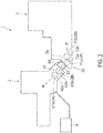
- FIG. 2 is a schematic plan view illustrating the beverage production line in which the conveying equipment according to the first embodiment of the present invention is used
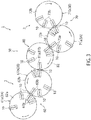
- Fig. 3 is a schematic plan view illustrating the conveying equipment according to the first embodiment of the present invention
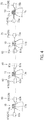
- Fig. 4 is a cross-sectional view illustrating the conveying equipment according to the first embodiment of the present invention
- Fig. 5(a) is a schematic plan view illustrating the beverage production line before the conveying equipment according to the first embodiment of the present invention is used
- Fig. 5(b) is a schematic plan view illustrating the beverage production line after the conveying equipment according to the first embodiment of the present invention has been used.
- a beverage production line 1 includes a molding device 2 that blow-molds a preform into the bottle 10, a filling device 3 that performs processing such as cleaning of the bottle 10 and filling of the bottle 10 with a beverage, and a conveying equipment 50 provided across the molding device 2 and the filling device 3.
- a preform supply machine 4 that supplies the preform to the molding device 2 is installed. Since the preform supply machine 4 can adopt a known configuration, a detailed description thereof will be omitted in the present specification.
- the molding device 2 heats the preform supplied from the preform supply machine 4 and then biaxially stretch blow-molds the preform to produce the bottle 10.
- the molding device 2 is provided with a plurality of conveyance lines that rotate and convey the molded bottle 10.
- conveyance units 2A and 2B of the two conveyance lines on the downstream side of the molding device 2 are used as a first upper rotation conveyance unit 61a and a first lower rotation conveyance unit 61b, which will be described later, of a first conveyance line 60, which will be described later, of the conveying equipment 50 (see Figs. 2 to 4 ).
- the configuration of the molding device 2 can adopt a known configuration, a detailed description thereof will be omitted in the present specification.
- the conveying equipment 50 is provided in the molding device 2 and includes the first conveyance line 60 that conveys the bottle 10 and a second conveyance line 70 provided in the filling device 3. Between the first conveyance line 60 and the second conveyance line 70, an adjustment rotation conveyance unit 80 that rotates while gripping at least one of the flange upper portion 17a and the flange lower portion 17b of the bottle 10 is provided.
- the first conveyance line 60 has a first upper rotation conveyance unit 61a that rotates while gripping the flange upper portion 17a and conveys the bottle 10 and a first lower rotation conveyance unit 61b that rotates while gripping the flange lower portion 17b and conveys the bottle 10.
- the first upper rotation conveyance unit 61a is provided further upstream than the first lower rotation conveyance unit 61b, and transfers the bottle 10 to the first lower rotation conveyance unit 61b.
- the conveyance units 2A and 2B of the two conveyance lines on the downstream side of the molding device 2 are used as the first upper rotation conveyance unit 61a and the first lower rotation conveyance unit 61b of the first conveyance line 60.
- the first lower rotation conveyance unit 61b may be provided further upstream than the first upper rotation conveyance unit 61a. In this case, the first lower rotation conveyance unit 61b transfers the bottle 10 to the first upper rotation conveyance unit 61a (see Fig. 8(a) ).
- the first upper rotation conveyance unit 61a has a rotatable first upper wheel 62a and a plurality of upper gripping parts 63a provided on the first upper wheel 62a and arranged at equal intervals in a circumferential direction.
- the upper gripping part 63a rotates (revolves) as the first upper wheel 62a rotates.
- the first lower rotation conveyance unit 61b has a rotatable first lower wheel 62b and a plurality of lower gripping parts 63b provided on the first lower wheel 62b and arranged at equal intervals in the circumferential direction.
- the lower gripping part 63b rotates (revolves) as the first lower wheel 62b rotates.
- the first upper rotation conveyance unit 61a rotates clockwise in plan view in Fig. 3
- the first lower rotation conveyance unit 61b rotates counterclockwise in plan view in Fig. 3
- known grippers can be employed as the upper gripping part 63a and the lower gripping part 63b.
- Fig. 3 illustrates only some upper gripping parts 63a and lower gripping parts 63b.
- the adjustment rotation conveyance unit 80 has the upper gripping part 81a that is provided to be openable and closable and grips the flange upper portion 17a, and the lower gripping part 81b that is provided to be openable and closable and grips the flange lower portion 17b.
- a plurality of the upper gripping parts 81a and the lower gripping parts 81b are arranged at equal intervals in the circumferential direction on a rotatable adjustment rotation wheel 82.
- the upper gripping part 81a and the lower gripping part 81b rotate (revolve) as the adjustment rotation wheel 82 rotates.
- the upper gripping part 81a and the lower gripping part 81b rotate clockwise in plan view in Fig. 3 .
- known grippers can be employed as the upper gripping part 81a and the lower gripping part 81b.
- Fig. 3 illustrates only some upper gripping parts 81a and lower gripping parts 81b.
- the adjustment rotation conveyance unit 80 uses one of the upper gripping part 81a and the lower gripping part 81b to receive the bottle 10 from the first lower rotation conveyance unit 61b or the first upper rotation conveyance unit 61a of the first conveyance line 60. As illustrated in Fig. 4 , in the present embodiment, the adjustment rotation conveyance unit 80 uses the upper gripping part 81a to receive the bottle 10 from the lower gripping part 63b of the first lower rotation conveyance unit 61b. In this case, the upper gripping part 81a grips the flange upper portion 17a of the bottle 10 by changing the upper gripping part 81a from an open state to a closed state. At this time, the lower gripping part 81b is not used.
- the lower gripping part 81b is maintained in the open state so that the lower gripping part 81b and the lower gripping part 63b of the first lower rotation conveyance unit 61b do not interfere with each other.
- the adjustment rotation conveyance unit 80 uses the lower gripping part 81b to receive the bottle 10 from the upper gripping part 63a of the first upper rotation conveyance unit 61a (see Fig. 8(b) ).
- the lower gripping part 81b grips the flange lower portion 17b of the bottle 10 by changing the lower gripping part 81b from the open state to the closed state.
- the upper gripping part 81a is not used. In this case, the upper gripping part 81a is maintained in the open state so that the upper gripping part 81a and the upper gripping part 63a of the first upper rotation conveyance unit 61a do not interfere with each other.
- the adjustment rotation conveyance unit 80 when the adjustment rotation conveyance unit 80 transfers the bottle 10 to a second lower rotation conveyance unit 71b or a second upper rotation conveyance unit 71a, which will be described later, of the second conveyance line 70, the adjustment rotation conveyance unit 80 changes gripping of the bottle 10 from one gripping part gripping the bottle 10 to the other gripping part while the adjustment rotation conveyance unit 80 rotates and conveys the bottle 10, and uses the other gripping part to transfer the bottle 10 to the second lower rotation conveyance unit 71b or the second upper rotation conveyance unit 71a of the second conveyance line 70.
- the upstream conveyance unit 2B (the first lower rotation conveyance unit 61b in the present embodiment) of the adjustment rotation conveyance unit 80 and a downstream conveyance unit 3A (the second upper rotation conveyance unit 71a in the present embodiment) grip different portions of the bottle 10 (the flange upper portion 17a or the flange lower portion 17b), while the adjustment rotation conveyance unit 80 rotates and conveys the bottle 10, gripping of the bottle 10 is changed from one gripping part to the other gripping part.
- the adjustment rotation conveyance unit 80 uses the upper gripping part 81a to receive the bottle 10 from the lower gripping part 63b of the first lower rotation conveyance unit 61b and changes gripping of the bottle 10 from the upper gripping part 81a that has received the bottle 10 to the lower gripping part 81b. That is, in a state where the flange upper portion 17a of the bottle 10 is gripped by the upper gripping part 81a, the lower gripping part 81b located below the upper gripping part 81a is closed to grip the flange lower portion 17b. Thereafter, the upper gripping part 81a is opened, so that gripping of the bottle 10 is changed from the upper gripping part 81a to the lower gripping part 81b.
- the adjustment rotation conveyance unit 80 uses the lower gripping part 81b to transfer the bottle 10 to an upper gripping part 73a, which will be described later, of the second upper rotation conveyance unit 71a of the second conveyance line 70.
- the adjustment rotation conveyance unit 80 uses the lower gripping part 81b to receive the bottle 10 from the upper gripping part 63a of the first upper rotation conveyance unit 61a (see Fig.
- the adjustment rotation conveyance unit 80 uses the upper gripping part 81a to transfer the bottle 10 to the lower gripping part 73b, which will be described later, of the second lower rotation conveyance unit 71b of the second conveyance line 70 (see Fig. 8(e) ).
- the second conveyance line 70 has the second upper rotation conveyance unit 71a that rotates while gripping the flange upper portion 17a and conveys the bottle 10 and the second lower rotation conveyance unit 71b that rotates while gripping the flange lower portion 17b and conveys the bottle 10.
- the second upper rotation conveyance unit 71a is provided further upstream than the second lower rotation conveyance unit 71b, and receives the bottle 10 from the lower gripping part 81b.
- the upper gripping part 81a of the adjustment rotation conveyance unit 80 is maintained in the open state so that the second upper rotation conveyance unit 71a and the upper gripping part 81a do not interfere with each other.
- the second upper rotation conveyance unit 71a transfers the bottle 10 to the second lower rotation conveyance unit 71b.
- the conveyance units 3A and 3B of the two conveyance lines on the downstream side of the filling device 3 are used as the second upper rotation conveyance unit 71a and the second lower rotation conveyance unit 71b of the second conveyance line 70.
- the second lower rotation conveyance unit 71b receives the bottle 10 from the upper gripping part 81a (see Fig. 8(e) ).
- the lower gripping part 81b of the adjustment rotation conveyance unit 80 is maintained in the open state so that the lower gripping part 81b and the second lower rotation conveyance unit 71b do not interfere with each other. Then, the second lower rotation conveyance unit 71b transfers the bottle 10 to the second upper rotation conveyance unit 71a.
- the second upper rotation conveyance unit 71a has a rotatable second upper wheel 72a and a plurality of upper gripping parts 73a provided on the second upper wheel 72a and arranged at equal intervals in the circumferential direction.
- the upper gripping part 73a rotates (revolves) as the second upper wheel 72a rotates.
- the second lower rotation conveyance unit 71b has a rotatable second lower wheel 72b and a plurality of lower gripping parts 73b provided on the second lower wheel 72b and arranged at equal intervals in the circumferential direction.
- the lower gripping part 73b rotates (revolves) as the second lower wheel 72b rotates.
- the second upper rotation conveyance unit 71a rotates counterclockwise in plan view in Fig. 3
- the second lower rotation conveyance unit 71b rotates clockwise in plan view in Fig. 3
- known grippers can be employed as the upper gripping part 73a and the lower gripping part 73b.
- Fig. 3 illustrates only some upper gripping parts 73a and lower gripping parts 73b.
- the filling device 3 illustrated in Figs. 2 and 3 cleans and sterilizes the bottle 10, fills the bottle 10 with a beverage, and closes the bottle 10 filled with the beverage with a cap, thus producing a beverage-containing bottle.
- the filling device 3 is provided with a plurality of conveyance lines that rotate and convey the bottle 10.
- the conveyance units 3A and 3B of the two conveyance lines on the upstream side of the filling device 3 are used as the second upper rotation conveyance unit 71a and the second lower rotation conveyance unit 71b described above (see Figs. 2 to 4 ).
- the configuration of the filling device 3 can adopt a known configuration, a detailed description thereof will be omitted in the present specification.
- the most downstream conveyance unit 2B of the molding device 2 and the most upstream conveyance unit 3A of the filling device 3 may rotate in opposite directions from each other and may grip the same portion of the bottle 10. That is, when the conveyance unit 2B and the conveyance unit 3A are prepared separately, the conveyance unit 2B and the conveyance unit 3A may rotate in opposite directions from each other and may grip the flange lower portion 17b of the bottle 10, for example. In this case, even if the adjustment rotation conveyance unit 80 is provided, the molding device 2 and the filling device 3 cannot be connected. In such a case, as illustrated in Fig.
- the conveyance unit 3A of the filling device 3 is removed and the adjustment rotation conveyance unit 80 is provided, or although not illustrated, a wheel (a rotation conveyance unit rotating counterclockwise in plan view and having, for example, the upper gripping part 73a) is separately provided between the adjustment rotation conveyance unit 80 and conveyance unit 3A, whereby the molding device 2 and the filling device 3 can be connected.
- a wheel a rotation conveyance unit rotating counterclockwise in plan view and having, for example, the upper gripping part 73a
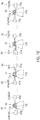
- FIGS. 6(a) to 6(f) are cross-sectional views illustrating a conveyance method according to the first embodiment of the present invention (views corresponding in part to Fig. 4 ).
- a preform for molding the bottle 10 is supplied from the preform supply machine 4 to the molding device 2.
- the preform is heated and then biaxially stretch blow-molded to mold the bottle 10 having a desired shape from the preform.
- the blow-molded bottle 10 is conveyed to the first conveyance line 60. Then, the bottle 10 is conveyed using the first conveyance line 60 (first conveyance step).
- the first upper rotation conveyance unit 61a uses the upper gripping part 63a to convey the bottle 10 clockwise in plan view.
- the first upper rotation conveyance unit 61a transfers the bottle 10 to the first lower rotation conveyance unit 61b ( Fig. 6(a) ).
- the lower gripping part 63b of the first lower rotation conveyance unit 61b grips the flange lower portion 17b of the bottle 10, and receives the bottle 10 from the upper gripping part 63a of the first upper rotation conveyance unit 61a.
- the first lower rotation conveyance unit 61b rotates counterclockwise in plan view and conveys the bottle 10.
- the adjustment rotation conveyance unit 80 uses the upper gripping part 81a to receive the bottle 10 from the first lower rotation conveyance unit 61b of the first conveyance line 60 (receiving step) ( Fig. 6(b) ).
- the upper gripping part 81a is changed from the open state to the closed state, and the upper gripping part 81a grips the flange upper portion 17a of the bottle 10.
- the lower gripping part 81b is maintained in the open state and does not interfere with the lower gripping part 63b of the first lower rotation conveyance unit 61b.
- the upper gripping part 81a that has received the bottle 10 rotates clockwise in plan view while gripping the flange upper portion 17a of the bottle 10, and conveys the bottle 10.
- gripping of the bottle 10 is changed from the upper gripping part 81a to the lower gripping part 81b (gripping change step) ( Fig. 6(c) ).
- the lower gripping part 81b is changed from the open state to the closed state while the upper gripping part 81a is maintained in the closed state. Accordingly, in a state where the upper gripping part 81a grips the flange upper portion 17a of the bottle 10, the lower gripping part 81b grips the flange lower portion 17b of the bottle 10. Next, the upper gripping part 81a is changed from the closed state to the open state, and the bottle 10 is opened ( Fig. 6(d) ). Next, in a state where the lower gripping part 81b grips the flange lower portion 17b of the bottle 10, the adjustment rotation conveyance unit 80 rotates clockwise in plan view and conveys the bottle 10.
- the adjustment rotation conveyance unit 80 uses the lower gripping part 81b to transfer the bottle 10 to the second upper rotation conveyance unit 71a of the second conveyance line 70 (transfer step) ( Fig. 6(e) ).
- the upper gripping part 73a of the second upper rotation conveyance unit 71a grips the flange upper portion 17a of the bottle 10, and receives the bottle 10 from the lower gripping part 81b.
- the upper gripping part 81a is maintained in the open state and does not interfere with the upper gripping part 73a of the second upper rotation conveyance unit 71a.
- the bottle 10 from the adjustment rotation conveyance unit 80 is transferred to the second conveyance line 70, and the bottle 10 is conveyed by the second conveyance line 70 (second conveyance step).
- the second upper rotation conveyance unit 71a rotates counterclockwise in plan view and conveys the bottle 10. Then, the second upper rotation conveyance unit 71a transfers the bottle 10 to the second lower rotation conveyance unit 71b ( Fig. 6(f) ).
- the lower gripping part 73b of the second lower rotation conveyance unit 71b grips the flange lower portion 17b of the bottle 10, and receives the bottle 10 from the upper gripping part 73a of the second upper rotation conveyance unit 71a. Thereafter, in the filling device 3, the bottle 10 is cleaned and sterilized, and the bottle 10 is filled with a beverage. Then, the bottle 10 filled with the beverage is closed with a cap to produce a beverage-containing bottle.
- the bottle 10 is conveyed from the molding device 2 to the filling device 3 using the conveying equipment 50.
- the first upper rotation conveyance unit 61a is provided further upstream than the first lower rotation conveyance unit 61b and the second upper rotation conveyance unit 71a is provided further upstream than the second lower rotation conveyance unit 71b
- the present invention is not limited to this example.
- the first lower rotation conveyance unit 61b may be provided further upstream than the first upper rotation conveyance unit 61a
- the second lower rotation conveyance unit 71b may be provided further upstream than the second upper rotation conveyance unit 71a. In this case, as illustrated in Figs.
- the first lower rotation conveyance unit 61b transfers the bottle 10 to the first upper rotation conveyance unit 61a ( Fig. 8(a) ).
- the adjustment rotation conveyance unit 80 uses the lower gripping part 81b to receive the bottle 10 from the first upper rotation conveyance unit 61a of the first conveyance line 60 ( Fig. 8(b) ).
- the adjustment rotation conveyance unit 80 changes gripping of the bottle 10 from the lower gripping part 81b to the upper gripping part 81a ( Figs. 8(c) to 8(d) ).
- the adjustment rotation conveyance unit 80 uses the upper gripping part 81a to transfer the bottle 10 to the second lower rotation conveyance unit 71b of the second conveyance line 70 ( Fig. 8(e) ). Then, the second lower rotation conveyance unit 71b transfers the bottle 10 to the second upper rotation conveyance unit 71a ( Fig. 8(f) ).
- the adjustment rotation conveyance unit 80 that rotates while gripping at least one of the flange upper portion 17a and the flange lower portion 17b of the bottle 10 is provided.
- the adjustment rotation conveyance unit 80 has the upper gripping part 81a that is provided to be openable and closable and grips the flange upper portion 17a of the bottle 10, and the lower gripping part 81b that is provided to be openable and closable and grips the flange lower portion 17b of the bottle 10.
- the bottle 10 can be conveyed from the molding device 2 to the filling device 3 regardless of the position at which the first upper rotation conveyance unit 61a or the first lower rotation conveyance unit 61b of the first conveyance line 60 and the second upper rotation conveyance unit 71a or the second lower rotation conveyance unit 71b of the second conveyance line 70 grip the bottle 10.
- the bottle 10 is received from the first lower rotation conveyance unit 61b or the first upper rotation conveyance unit 61a of the first conveyance line 60 by using one of the upper gripping part 81a and the lower gripping part 81b, and while the adjustment rotation conveyance unit 80 rotates and conveys the bottle 10, gripping of the bottle 10 is changed from the one gripping part to the other gripping part, and the bottle 10 can be transferred to the second upper rotation conveyance unit 71a or the second lower rotation conveyance unit 71b of the second conveyance line 70 by using the other gripping part. Consequently, the bottle 10 can be conveyed from the molding device 2 to the filling device 3.
- the molding device 2 and the filling device 3 can be conveyed from the molding device 2 to the filling device 3.
- the example has been described in which the conveyance units 2A and 2B of the two conveyance lines on the downstream side of the molding device 2 are used as the first upper rotation conveyance unit 61a and the first lower rotation conveyance unit 61b, and the conveyance units 3A and 3B of the two conveyance lines on the upstream side of the filling device 3 are used as the second upper rotation conveyance unit 71a and the second lower rotation conveyance unit 71b.
- the present invention is not limited to this example.
- the first upper rotation conveyance unit 61a, the first lower rotation conveyance unit 61b, the second upper rotation conveyance unit 71a, and the second lower rotation conveyance unit 71b may be provided in the molding device 2.
- FIG. 9 is a schematic plan view illustrating a conveying equipment according to the second embodiment of the present invention
- Fig. 10 is a cross-sectional view illustrating the conveying equipment according to the second embodiment of the present invention.
- Figs. 11(a) to 11(d) are cross-sectional views illustrating a conveyance method according to the second embodiment of the present invention (views corresponding in part to Fig. 10 ).
- the adjustment rotation conveyance unit 80 mainly uses the gripping part that has received the bottle 10 to transfer the bottle 10 to the second lower rotation conveyance unit 71b or the second upper rotation conveyance unit 71a of the second conveyance line 70.
- the same portions as those in the first embodiment will be assigned the same reference numerals and will not be described in detail.
- the first lower rotation conveyance unit 61b As illustrated in Fig. 9 , the first lower rotation conveyance unit 61b according to the present embodiment is provided further upstream than the first upper rotation conveyance unit 61a, and transfers the bottle 10 to the first upper rotation conveyance unit 61a.
- the first upper rotation conveyance unit 61a rotates counterclockwise in plan view in Fig. 9
- the first lower rotation conveyance unit 61b rotates clockwise in plan view in Fig. 9 .
- the adjustment rotation conveyance unit 80 uses one of the gripping parts gripping the bottle 10 to transfer the bottle 10 to the second lower rotation conveyance unit 71b or the second upper rotation conveyance unit 71a, which will be described later, of the second conveyance line 70. That is, as illustrated in Fig.
- the adjustment rotation conveyance unit 80 uses the lower gripping part 81b to receive the bottle 10 from the upper gripping part 63a of the first upper rotation conveyance unit 61a and uses the lower gripping part 81b that has received the bottle 10 to transfer the bottle 10 to the upper gripping part 73a of the second upper rotation conveyance unit 71a.
- the adjustment rotation conveyance unit 80 uses the lower gripping part 81b to receive the bottle 10 from the upper gripping part 63a of the first upper rotation conveyance unit 61a and uses the lower gripping part 81b that has received the bottle 10 to transfer the bottle 10 to the upper gripping part 73a of the second upper rotation conveyance unit 71a.
- the adjustment rotation conveyance unit 80 uses the upper gripping part 81a to receive the bottle 10 from the lower gripping part 63b of the first lower rotation conveyance unit 61b (see Fig. 13(b) ) and uses the upper gripping part 81a that has received the bottle 10 to transfer the bottle 10 to the lower gripping part 73b of the second lower rotation conveyance unit 71b (see Fig. 13(c) ).
- the bottle 10 is conveyed using the first conveyance line 60 (first conveyance step).
- the first lower rotation conveyance unit 61b uses the lower gripping part 63b to convey the bottle 10 clockwise in plan view.
- the first lower rotation conveyance unit 61b transfers the bottle 10 to the first upper rotation conveyance unit 61a ( Fig. 11(a) ).
- the upper gripping part 63a of the first upper rotation conveyance unit 61a grips the flange upper portion 17a of the bottle 10, and receives the bottle 10 from the lower gripping part 63b of the first lower rotation conveyance unit 61b.
- the first upper rotation conveyance unit 61a rotates counterclockwise in plan view and conveys the bottle 10.
- the adjustment rotation conveyance unit 80 uses the lower gripping part 81b to receive the bottle 10 from the first upper rotation conveyance unit 61a of the first conveyance line 60 (receiving step) ( Fig. 11(b) ).
- the lower gripping part 81b is changed from the open state to the closed state, and the lower gripping part 81b grips the flange lower portion 17b of the bottle 10.
- the upper gripping part 81a is maintained in the open state and does not interfere with the upper gripping part 63a of the first upper rotation conveyance unit 61a.
- the adjustment rotation conveyance unit 80 rotates clockwise in plan view and conveys the bottle 10. Then, the adjustment rotation conveyance unit 80 uses the lower gripping part 81b that has received the bottle 10 to transfer the bottle 10 to the second upper rotation conveyance unit 71a of the second conveyance line 70 (transfer step) ( Fig. 11(c) ).
- the upper gripping part 73a of the second upper rotation conveyance unit 71a grips the flange upper portion 17a of the bottle 10, and receives the bottle 10 from the lower gripping part 81b.
- the upper gripping part 81a is maintained in the open state and does not interfere with the upper gripping part 73a of the second upper rotation conveyance unit 71a.
- the bottle 10 from the adjustment rotation conveyance unit 80 is transferred to the second conveyance line 70, and the bottle 10 is conveyed by the second conveyance line 70 (second conveyance step).
- the second upper rotation conveyance unit 71a transfers the bottle 10 to the second lower rotation conveyance unit 71b ( Fig. 11(d) ).
- the bottle 10 is cleaned and sterilized, and the bottle 10 is filled with a beverage.
- the bottle 10 filled with the beverage is closed with a cap to produce a beverage-containing bottle.
- the bottle 10 is conveyed from the molding device 2 to the filling device 3 using the conveying equipment 50.
- the first lower rotation conveyance unit 61b is provided further upstream than the first upper rotation conveyance unit 61a and the second upper rotation conveyance unit 71a is provided further upstream than the second lower rotation conveyance unit 71b
- the present invention is not limited to this example.
- the first upper rotation conveyance unit 61a may be provided further upstream than the first lower rotation conveyance unit 61b
- the second lower rotation conveyance unit 71b may be provided further upstream than the second upper rotation conveyance unit 71a. In this case, as illustrated in Figs.
- the first upper rotation conveyance unit 61a transfers the bottle 10 to the first lower rotation conveyance unit 61b ( Fig. 13(a) ).
- the adjustment rotation conveyance unit 80 uses the upper gripping part 81a to receive the bottle 10 from the first lower rotation conveyance unit 61b of the first conveyance line 60 ( Fig. 13(b) ).
- the adjustment rotation conveyance unit 80 uses the upper gripping part 81a to transfer the bottle 10 to the second lower rotation conveyance unit 71b of the second conveyance line 70 ( Fig. 13(c) ).
- the second lower rotation conveyance unit 71b transfers the bottle 10 to the second upper rotation conveyance unit 71a ( Fig. 13(d) ).
- the bottle 10 is received from the first lower rotation conveyance unit 61b or the first upper rotation conveyance unit 61a of the first conveyance line 60 by using one of the upper gripping part 81a and the lower gripping part 81b, and using the one gripping part, the bottle 10 can be transferred to the second upper rotation conveyance unit 71a or the second lower rotation conveyance unit 71b of the second conveyance line 70. Consequently, the bottle 10 can be conveyed from the molding device 2 to the filling device 3, and the molding device 2 and the filling device 3 can be connected to each other regardless of the specifications of the molding device 2 and the filling device 3.
Landscapes
- Engineering & Computer Science (AREA)
- Mechanical Engineering (AREA)
- Filling Of Jars Or Cans And Processes For Cleaning And Sealing Jars (AREA)
- Specific Conveyance Elements (AREA)
Abstract
Description
- The present invention relates to a conveying equipment for a bottle having a flange portion, an adjustment rotation conveyance unit, and a conveyance method.
- Conventionally, for example, a beverage production line for performing processing from molding of a PET bottle as an article to filling of a beverage includes a molding device for molding a PET bottle and a filling device for filling a PET bottle with a beverage or the like. In addition, a conveying equipment for conveying a PET bottle between the molding device and the filling device and connecting the molding device and the filling device to each other is provided (for example, Patent Literature 1).
- As a method of conveying a container among the molding device, the conveying equipment, and the filling device as described above, a method of conveying the container while alternately gripping an upper portion and a lower portion of a flange portion of a bottle with a gripper of a rotating wheel is generally used.
- However, at the time of conveyance, for example, in the wheels having the grippers that grip the upper portion of the flange portion, the grippers interfere with each other, so that the bottle cannot be delivered. In this case, it is necessary to produce a device in which some device is mirror-inverted in design and to connect the wheels to each other. For example, it is necessary to arrange in a row the wheel having the gripper for gripping the upper portion of the flange portion and the wheel having the gripper for gripping the lower portion of the flange portion. At this time, the two wheels need to rotate in opposite directions. On the other hand, when a mirror-reversed device is produced, a special specification is required, and a great burden is imposed on the design of the device, the arrangement of parts and the assembly of the device. Depending on devices, it may be difficult to produce a mirror-inverted device.
- Patent Literature 1:
JP 11-502175 A - The present invention has been made in light of such a problem, and an object thereof is to provide a conveying equipment, an adjustment rotation conveyance unit, and a conveyance method that can connect a molding device and a filling device to each other regardless of the specifications of the molding device and the filling device.
- The present invention is a conveying equipment for a bottle having a flange portion, and the conveying equipment includes a first conveyance line, including a first upper rotation conveyance unit that rotates while gripping a flange upper portion located above the flange portion of the bottle and conveys the bottle and a first lower rotation conveyance unit that rotates while gripping a flange lower portion located below the flange portion of the bottle and conveys the bottle, and a second conveyance line including a second upper rotation conveyance unit that rotates while gripping the flange upper portion of the bottle and conveys the bottle and a second lower rotation conveyance unit that rotates while gripping the flange lower portion of the bottle and conveys the bottle, in which between the first conveyance line and the second conveyance line, an adjustment rotation conveyance unit that rotates while gripping at least one of the flange upper portion and the flange lower portion of the bottle is provided, and the adjustment rotation conveyance unit includes an upper gripping part that is provided to be openable and closable and grips the flange upper portion of the bottle and a lower gripping part that is provided to be openable and closable and grips the flange lower portion of the bottle.
- The present invention is the conveying equipment, in which the adjustment rotation conveyance unit uses one of the upper gripping part and the lower gripping part to receive the bottle from the first lower rotation conveyance unit or the first upper rotation conveyance unit of the first conveyance line, and uses the one gripping part to transfer the bottle to the second lower rotation conveyance unit or the second upper rotation conveyance unit of the second conveyance line.
- The present invention is the conveying equipment in which the adjustment rotation conveyance unit uses one of the upper gripping part and the lower gripping part to receive the bottle from the first lower rotation conveyance unit or the first upper rotation conveyance unit of the first conveyance line, and, while the adjustment rotation conveyance unit rotates and conveys the bottle, changes gripping of the bottle from the one gripping part to the other gripping part, and the adjustment rotation conveyance unit uses the other gripping part to transfer the bottle to the second upper rotation conveyance unit or the second lower rotation conveyance unit of the second conveyance line.
- The present invention is an adjustment rotation conveyance unit provided between a first conveyance line including a first upper rotation conveyance unit that rotates while gripping a flange upper portion located above the flange portion of the bottle and conveys the bottle and a first lower rotation conveyance unit that rotates while gripping a flange lower portion located below the flange portion of the bottle and conveys the bottle, and a second conveyance line including a second upper rotation conveyance unit that rotates while gripping the flange upper portion of the bottle and conveys the bottle and a second lower rotation conveyance unit that rotates while gripping the flange lower portion of the bottle and conveys the bottle, and in the adjustment rotation conveyance unit rotating while gripping at least one of the flange upper portion and the flange lower portion of the bottle, the adjustment rotation conveyance unit includes an upper gripping part provided to be openable and closable and gripping the flange upper portion of the bottle and a lower gripping part provided to be openable and closable and gripping the flange lower portion of the bottle.
- The present invention is a conveyance method of a bottle having a flange portion, and the conveyance method includes a first conveyance step of conveying a bottle using a first conveyance line including a first upper rotation conveyance unit that rotates while gripping a flange upper portion located above the flange portion of the bottle and conveys the bottle and a first lower rotation conveyance unit that rotates while gripping a flange lower portion located below the flange portion of the bottle and conveys the bottle, a second conveyance step of conveying the bottle using a second conveyance line including a second upper rotation conveyance unit that rotates while gripping the flange upper portion of the bottle and conveys the bottle and a second lower rotation conveyance unit that rotates while gripping the flange lower portion of the bottle and conveys the bottle, and an adjustment conveyance step of, between the first conveyance step and the second conveyance step, conveying the bottle from the first conveyance line to the second conveyance line using an adjustment rotation conveyance unit that rotates while gripping at least one of the flange upper portion of the bottle and the flange lower portion of the bottle, and in this conveyance method, the adjustment rotation conveyance unit includes an upper gripping part that is provided to be openable and closable and grips the flange upper portion of the bottle and a lower gripping part that is provided to be openable and closable and grips the flange lower portion of the bottle.
- The present invention is the conveyance method in which the adjustment conveyance step includes a receiving step of using one of the upper gripping part and the lower gripping part to receive the bottle from the first lower rotation conveyance unit or the first upper rotation conveyance unit of the first conveyance line and a transfer step of using the one gripping part to transfer the bottle to the second lower rotation conveyance unit or the second upper rotation conveyance unit of the second conveyance line.
- The present invention is the conveyance method in which the adjustment conveyance step includes a receiving step of using one of the upper gripping part and the lower gripping part to receive the bottle from the first lower rotation conveyance unit or the first upper rotation conveyance unit of the first conveyance line, a gripping change step of changing gripping of the bottle from the one gripping part to the other gripping part while the adjustment rotation conveyance unit rotates and conveys the bottle, and a transfer step of using the other gripping part to transfer the bottle to the second upper rotation conveyance unit or the second lower rotation conveyance unit of the second conveyance line.
- According to the present invention, the molding device and the filling device can be connected to each other regardless of the specifications of the molding device and the filling device.
-
-
Fig. 1 is a front view illustrating a bottle conveyed by a conveying equipment according to a first embodiment of the present invention. -
Fig. 2 is a schematic plan view illustrating a beverage production line in which the conveying equipment according to the first embodiment of the present invention is used. -
Fig. 3 is a schematic plan view illustrating the conveying equipment according to the first embodiment of the present invention. -
Fig. 4 is a cross-sectional view illustrating the conveying equipment according to the first embodiment of the present invention (a cross-sectional view taken along line IV-IV inFig. 2 ). -
Fig. 5(a) is a schematic plan view illustrating the beverage production line before the conveying equipment according to the first embodiment of the present invention is used, andFig. 5(b) is a schematic plan view illustrating the beverage production line after the conveying equipment according to the first embodiment of the present invention has been used. -
Figs. 6(a) to 6(f) are cross-sectional views illustrating a conveyance method according to the first embodiment of the present invention. -
Fig. 7 is a cross-sectional view illustrating a modification of the conveying equipment according to the first embodiment of the present invention. -
Figs. 8(a) to 8(f) are cross-sectional views illustrating a modification of the conveyance method according to the first embodiment of the present invention. -
Fig. 9 is a schematic plan view illustrating a conveying equipment according to a second embodiment of the present invention. -
Fig. 10 is a cross-sectional view illustrating the conveying equipment according to the second embodiment of the present invention (a cross-sectional view taken along line X-X inFig. 9 ). -
Figs. 11(a) to 11(d) are cross-sectional views illustrating a conveyance method according to the second embodiment of the present invention. -
Fig. 12 is a cross-sectional view illustrating a modification of the conveying equipment according to the second embodiment of the present invention. -
Figs. 13(a) to 13(d) are cross-sectional views illustrating a modification of the conveyance method according to the second embodiment of the present invention. - A first embodiment of the present invention will be described below with reference to the drawings.
Figs. 1 to 6 illustrate the first embodiment of the present invention. - First, with reference to
Fig. 1 , a bottle conveyed by a conveying equipment according to the present embodiment will be described. The terms "above" and "below", as used herein, mean above and below, respectively, of an upright bottle (Fig. 1 ). - A
bottle 10 illustrated inFig. 1 includes amouth portion 11, aneck portion 13 provided below themouth portion 11, ashoulder portion 12 provided below theneck portion 13, atrunk portion 20 provided below theshoulder portion 12, and abottom portion 30 provided below thetrunk portion 20. - The
mouth portion 11 includes ascrew portion 14, onto which a cap (not illustrated) is to be screwed, and aflange portion 17 provided below thescrew portion 14. A flangeupper portion 17a gripped by an upper grippingpart 81a, which will be described later, or the like is provided above theflange portion 17, and a flangelower portion 17b gripped by a lowergripping part 81b, which will be described later, or the like is provided below theflange portion 17. - The
bottle 10 thus configured can be made by performing biaxial stretching blow molding on a preform (not illustrated) made by performing injection molding on a synthetic resin material. As materials of the preform, that is, thebottle 10, a thermoplastic resin such as polyethylene (PE), polypropylene (PP), polyethylene-terephthalate (PET), polyethylene naphthalate (PEN), or polycarbonate (PC) can be used. - Although an example in which the present invention is applied to a container as a PET bottle for beverages will be described, in addition to the
bottle 10 thus configured, the present invention can be applied to conveyance of various containers. - Next, with reference to
Figs. 2 to 5 , a beverage production line in which the conveying equipment is used will be described.Fig. 2 is a schematic plan view illustrating the beverage production line in which the conveying equipment according to the first embodiment of the present invention is used, andFig. 3 is a schematic plan view illustrating the conveying equipment according to the first embodiment of the present invention.Fig. 4 is a cross-sectional view illustrating the conveying equipment according to the first embodiment of the present invention.Fig. 5(a) is a schematic plan view illustrating the beverage production line before the conveying equipment according to the first embodiment of the present invention is used, andFig. 5(b) is a schematic plan view illustrating the beverage production line after the conveying equipment according to the first embodiment of the present invention has been used. - As illustrated in
Figs. 2 and3 , abeverage production line 1 includes amolding device 2 that blow-molds a preform into thebottle 10, afilling device 3 that performs processing such as cleaning of thebottle 10 and filling of thebottle 10 with a beverage, and aconveying equipment 50 provided across themolding device 2 and thefilling device 3. Among these, near themolding device 2, apreform supply machine 4 that supplies the preform to themolding device 2 is installed. Since thepreform supply machine 4 can adopt a known configuration, a detailed description thereof will be omitted in the present specification. - The
molding device 2 heats the preform supplied from thepreform supply machine 4 and then biaxially stretch blow-molds the preform to produce thebottle 10. Themolding device 2 is provided with a plurality of conveyance lines that rotate and convey the moldedbottle 10. In the present embodiment,conveyance units molding device 2 are used as a first upperrotation conveyance unit 61a and a first lowerrotation conveyance unit 61b, which will be described later, of afirst conveyance line 60, which will be described later, of the conveying equipment 50 (seeFigs. 2 to 4 ). In addition, since the configuration of themolding device 2 can adopt a known configuration, a detailed description thereof will be omitted in the present specification. - Next, the
conveying equipment 50 will be described with reference toFigs. 2 to 5 . As illustrated inFigs. 2 and3 , theconveying equipment 50 is provided in themolding device 2 and includes thefirst conveyance line 60 that conveys thebottle 10 and asecond conveyance line 70 provided in thefilling device 3. Between thefirst conveyance line 60 and thesecond conveyance line 70, an adjustmentrotation conveyance unit 80 that rotates while gripping at least one of the flangeupper portion 17a and the flangelower portion 17b of thebottle 10 is provided. - As illustrated in
Figs. 3 to 5 , thefirst conveyance line 60 has a first upperrotation conveyance unit 61a that rotates while gripping the flangeupper portion 17a and conveys thebottle 10 and a first lowerrotation conveyance unit 61b that rotates while gripping the flangelower portion 17b and conveys thebottle 10. The first upperrotation conveyance unit 61a is provided further upstream than the first lowerrotation conveyance unit 61b, and transfers thebottle 10 to the first lowerrotation conveyance unit 61b. In the present embodiment, as described above, theconveyance units molding device 2 are used as the first upperrotation conveyance unit 61a and the first lowerrotation conveyance unit 61b of thefirst conveyance line 60. As illustrated inFig. 7 , the first lowerrotation conveyance unit 61b may be provided further upstream than the first upperrotation conveyance unit 61a. In this case, the first lowerrotation conveyance unit 61b transfers thebottle 10 to the first upperrotation conveyance unit 61a (seeFig. 8(a) ). - The first upper
rotation conveyance unit 61a has a rotatable firstupper wheel 62a and a plurality of uppergripping parts 63a provided on the firstupper wheel 62a and arranged at equal intervals in a circumferential direction. The uppergripping part 63a rotates (revolves) as the firstupper wheel 62a rotates. Similarly, the first lowerrotation conveyance unit 61b has a rotatable firstlower wheel 62b and a plurality of lowergripping parts 63b provided on the firstlower wheel 62b and arranged at equal intervals in the circumferential direction. The lowergripping part 63b rotates (revolves) as the firstlower wheel 62b rotates. In the present embodiment, the first upperrotation conveyance unit 61a rotates clockwise in plan view inFig. 3 , and the first lowerrotation conveyance unit 61b rotates counterclockwise in plan view inFig. 3 . As the uppergripping part 63a and the lowergripping part 63b, known grippers can be employed.Fig. 3 illustrates only some uppergripping parts 63a and lowergripping parts 63b. - As illustrated in
Figs. 3 and4 , the adjustmentrotation conveyance unit 80 has the uppergripping part 81a that is provided to be openable and closable and grips the flangeupper portion 17a, and the lowergripping part 81b that is provided to be openable and closable and grips the flangelower portion 17b. A plurality of the uppergripping parts 81a and the lowergripping parts 81b are arranged at equal intervals in the circumferential direction on a rotatableadjustment rotation wheel 82. The uppergripping part 81a and the lowergripping part 81b rotate (revolve) as theadjustment rotation wheel 82 rotates. In the present embodiment, the uppergripping part 81a and the lowergripping part 81b rotate clockwise in plan view inFig. 3 . As the uppergripping part 81a and the lowergripping part 81b, known grippers can be employed.Fig. 3 illustrates only some uppergripping parts 81a and lowergripping parts 81b. - The adjustment
rotation conveyance unit 80 uses one of the uppergripping part 81a and the lowergripping part 81b to receive thebottle 10 from the first lowerrotation conveyance unit 61b or the first upperrotation conveyance unit 61a of thefirst conveyance line 60. As illustrated inFig. 4 , in the present embodiment, the adjustmentrotation conveyance unit 80 uses the uppergripping part 81a to receive thebottle 10 from the lowergripping part 63b of the first lowerrotation conveyance unit 61b. In this case, the uppergripping part 81a grips the flangeupper portion 17a of thebottle 10 by changing the uppergripping part 81a from an open state to a closed state. At this time, the lowergripping part 81b is not used. In this case, the lowergripping part 81b is maintained in the open state so that the lowergripping part 81b and the lowergripping part 63b of the first lowerrotation conveyance unit 61b do not interfere with each other. As illustrated inFig. 7 , when the first lowerrotation conveyance unit 61b is provided further upstream than the first upperrotation conveyance unit 61a, the adjustmentrotation conveyance unit 80 uses the lowergripping part 81b to receive thebottle 10 from the uppergripping part 63a of the first upperrotation conveyance unit 61a (seeFig. 8(b) ). In this case, the lowergripping part 81b grips the flangelower portion 17b of thebottle 10 by changing the lowergripping part 81b from the open state to the closed state. At this time, the uppergripping part 81a is not used. In this case, the uppergripping part 81a is maintained in the open state so that the uppergripping part 81a and the uppergripping part 63a of the first upperrotation conveyance unit 61a do not interfere with each other. - As illustrated in
Fig. 4 , when the adjustmentrotation conveyance unit 80 transfers thebottle 10 to a second lowerrotation conveyance unit 71b or a second upperrotation conveyance unit 71a, which will be described later, of thesecond conveyance line 70, the adjustmentrotation conveyance unit 80 changes gripping of thebottle 10 from one gripping part gripping thebottle 10 to the other gripping part while the adjustmentrotation conveyance unit 80 rotates and conveys thebottle 10, and uses the other gripping part to transfer thebottle 10 to the second lowerrotation conveyance unit 71b or the second upperrotation conveyance unit 71a of thesecond conveyance line 70. That is, when theupstream conveyance unit 2B (the first lowerrotation conveyance unit 61b in the present embodiment) of the adjustmentrotation conveyance unit 80 and adownstream conveyance unit 3A (the second upperrotation conveyance unit 71a in the present embodiment) grip different portions of the bottle 10 (the flangeupper portion 17a or the flangelower portion 17b), while the adjustmentrotation conveyance unit 80 rotates and conveys thebottle 10, gripping of thebottle 10 is changed from one gripping part to the other gripping part. In the present embodiment, the adjustmentrotation conveyance unit 80 uses the uppergripping part 81a to receive thebottle 10 from the lowergripping part 63b of the first lowerrotation conveyance unit 61b and changes gripping of thebottle 10 from the uppergripping part 81a that has received thebottle 10 to the lowergripping part 81b. That is, in a state where the flangeupper portion 17a of thebottle 10 is gripped by the uppergripping part 81a, the lowergripping part 81b located below the uppergripping part 81a is closed to grip the flangelower portion 17b. Thereafter, the uppergripping part 81a is opened, so that gripping of thebottle 10 is changed from the uppergripping part 81a to the lowergripping part 81b. Then, the adjustmentrotation conveyance unit 80 uses the lowergripping part 81b to transfer thebottle 10 to an uppergripping part 73a, which will be described later, of the second upperrotation conveyance unit 71a of thesecond conveyance line 70. As illustrated inFig. 7 , when the first lowerrotation conveyance unit 61b is provided further upstream than the first upperrotation conveyance unit 61a and the second lowerrotation conveyance unit 71b is provided further upstream than the second upperrotation conveyance unit 71a, the adjustmentrotation conveyance unit 80 uses the lowergripping part 81b to receive thebottle 10 from the uppergripping part 63a of the first upperrotation conveyance unit 61a (seeFig. 8(b) ) and changes gripping of thebottle 10 from the lowergripping part 81b that has received thebottle 10 to the uppergripping part 81a (seeFigs. 8(c) to 8(d) ). Then, the adjustmentrotation conveyance unit 80 uses the uppergripping part 81a to transfer thebottle 10 to the lowergripping part 73b, which will be described later, of the second lowerrotation conveyance unit 71b of the second conveyance line 70 (seeFig. 8(e) ). - As illustrated in
Figs. 3 and4 , thesecond conveyance line 70 has the second upperrotation conveyance unit 71a that rotates while gripping the flangeupper portion 17a and conveys thebottle 10 and the second lowerrotation conveyance unit 71b that rotates while gripping the flangelower portion 17b and conveys thebottle 10. As illustrated inFigs. 3 and4 , the second upperrotation conveyance unit 71a is provided further upstream than the second lowerrotation conveyance unit 71b, and receives thebottle 10 from the lowergripping part 81b. At this time, the uppergripping part 81a of the adjustmentrotation conveyance unit 80 is maintained in the open state so that the second upperrotation conveyance unit 71a and the uppergripping part 81a do not interfere with each other. Then, the second upperrotation conveyance unit 71a transfers thebottle 10 to the second lowerrotation conveyance unit 71b. In the present embodiment, theconveyance units filling device 3 are used as the second upperrotation conveyance unit 71a and the second lowerrotation conveyance unit 71b of thesecond conveyance line 70. As illustrated inFig. 7 , when the second lowerrotation conveyance unit 71b is provided further upstream than the second upperrotation conveyance unit 71a, the second lowerrotation conveyance unit 71b receives thebottle 10 from the uppergripping part 81a (seeFig. 8(e) ). In this case, the lowergripping part 81b of the adjustmentrotation conveyance unit 80 is maintained in the open state so that the lowergripping part 81b and the second lowerrotation conveyance unit 71b do not interfere with each other. Then, the second lowerrotation conveyance unit 71b transfers thebottle 10 to the second upperrotation conveyance unit 71a. - The second upper
rotation conveyance unit 71a has a rotatable secondupper wheel 72a and a plurality of uppergripping parts 73a provided on the secondupper wheel 72a and arranged at equal intervals in the circumferential direction. The uppergripping part 73a rotates (revolves) as the secondupper wheel 72a rotates. Similarly, the second lowerrotation conveyance unit 71b has a rotatable secondlower wheel 72b and a plurality of lowergripping parts 73b provided on the secondlower wheel 72b and arranged at equal intervals in the circumferential direction. The lowergripping part 73b rotates (revolves) as the secondlower wheel 72b rotates. In the present embodiment, the second upperrotation conveyance unit 71a rotates counterclockwise in plan view inFig. 3 , and the second lowerrotation conveyance unit 71b rotates clockwise in plan view inFig. 3 . As the uppergripping part 73a and the lowergripping part 73b, known grippers can be employed.Fig. 3 illustrates only some uppergripping parts 73a and lowergripping parts 73b. - The filling
device 3 illustrated inFigs. 2 and3 cleans and sterilizes thebottle 10, fills thebottle 10 with a beverage, and closes thebottle 10 filled with the beverage with a cap, thus producing a beverage-containing bottle. The fillingdevice 3 is provided with a plurality of conveyance lines that rotate and convey thebottle 10. In the present embodiment, as described above, theconveyance units filling device 3 are used as the second upperrotation conveyance unit 71a and the second lowerrotation conveyance unit 71b described above (seeFigs. 2 to 4 ). In addition, since the configuration of thefilling device 3 can adopt a known configuration, a detailed description thereof will be omitted in the present specification. - As illustrated in
Fig. 5(a) , the mostdownstream conveyance unit 2B of themolding device 2 and the mostupstream conveyance unit 3A of thefilling device 3 may rotate in opposite directions from each other and may grip the same portion of thebottle 10. That is, when theconveyance unit 2B and theconveyance unit 3A are prepared separately, theconveyance unit 2B and theconveyance unit 3A may rotate in opposite directions from each other and may grip the flangelower portion 17b of thebottle 10, for example. In this case, even if the adjustmentrotation conveyance unit 80 is provided, themolding device 2 and thefilling device 3 cannot be connected. In such a case, as illustrated inFig. 5(b) , for example, theconveyance unit 3A of thefilling device 3 is removed and the adjustmentrotation conveyance unit 80 is provided, or although not illustrated, a wheel (a rotation conveyance unit rotating counterclockwise in plan view and having, for example, the uppergripping part 73a) is separately provided between the adjustmentrotation conveyance unit 80 andconveyance unit 3A, whereby themolding device 2 and thefilling device 3 can be connected. - Next, an operation of the present embodiment will be explained with reference to
Figs. 6(a) to 6(f) . Here, a conveyance method of thebottle 10 using the conveyingequipment 50 illustrated inFigs. 2 to 5 will be described.Figs. 6(a) to 6(f) are cross-sectional views illustrating a conveyance method according to the first embodiment of the present invention (views corresponding in part toFig. 4 ). - First, a preform for molding the
bottle 10 is supplied from thepreform supply machine 4 to themolding device 2. In themolding device 2, the preform is heated and then biaxially stretch blow-molded to mold thebottle 10 having a desired shape from the preform. - The blow-molded
bottle 10 is conveyed to thefirst conveyance line 60. Then, thebottle 10 is conveyed using the first conveyance line 60 (first conveyance step). In this case, first, the first upperrotation conveyance unit 61a uses the uppergripping part 63a to convey thebottle 10 clockwise in plan view. Next, the first upperrotation conveyance unit 61a transfers thebottle 10 to the first lowerrotation conveyance unit 61b (Fig. 6(a) ). At this time, the lowergripping part 63b of the first lowerrotation conveyance unit 61b grips the flangelower portion 17b of thebottle 10, and receives thebottle 10 from the uppergripping part 63a of the first upperrotation conveyance unit 61a. Next, in a state where the lowergripping part 63b that has received thebottle 10 grips the flangelower portion 17b of thebottle 10, the first lowerrotation conveyance unit 61b rotates counterclockwise in plan view and conveys thebottle 10. - Next, the
bottle 10 from the first lowerrotation conveyance unit 61b is conveyed to the adjustmentrotation conveyance unit 80, and the adjustmentrotation conveyance unit 80 conveys thebottle 10 from thefirst conveyance line 60 to the second conveyance line 70 (adjustment conveyance step). In this case, first, the adjustmentrotation conveyance unit 80 uses the uppergripping part 81a to receive thebottle 10 from the first lowerrotation conveyance unit 61b of the first conveyance line 60 (receiving step) (Fig. 6(b) ). At this time, the uppergripping part 81a is changed from the open state to the closed state, and the uppergripping part 81a grips the flangeupper portion 17a of thebottle 10. In this case, the lowergripping part 81b is maintained in the open state and does not interfere with the lowergripping part 63b of the first lowerrotation conveyance unit 61b. Next, the uppergripping part 81a that has received thebottle 10 rotates clockwise in plan view while gripping the flangeupper portion 17a of thebottle 10, and conveys thebottle 10. At this time, while the adjustmentrotation conveyance unit 80 rotates and conveys thebottle 10, gripping of thebottle 10 is changed from the uppergripping part 81a to the lowergripping part 81b (gripping change step) (Fig. 6(c) ). When gripping of thebottle 10 is changed, first, the lowergripping part 81b is changed from the open state to the closed state while the uppergripping part 81a is maintained in the closed state. Accordingly, in a state where the uppergripping part 81a grips the flangeupper portion 17a of thebottle 10, the lowergripping part 81b grips the flangelower portion 17b of thebottle 10. Next, the uppergripping part 81a is changed from the closed state to the open state, and thebottle 10 is opened (Fig. 6(d) ). Next, in a state where the lowergripping part 81b grips the flangelower portion 17b of thebottle 10, the adjustmentrotation conveyance unit 80 rotates clockwise in plan view and conveys thebottle 10. Then, the adjustmentrotation conveyance unit 80 uses the lowergripping part 81b to transfer thebottle 10 to the second upperrotation conveyance unit 71a of the second conveyance line 70 (transfer step) (Fig. 6(e) ). At this time, the uppergripping part 73a of the second upperrotation conveyance unit 71a grips the flangeupper portion 17a of thebottle 10, and receives thebottle 10 from the lowergripping part 81b. In this case, the uppergripping part 81a is maintained in the open state and does not interfere with the uppergripping part 73a of the second upperrotation conveyance unit 71a. - Thereafter, the
bottle 10 from the adjustmentrotation conveyance unit 80 is transferred to thesecond conveyance line 70, and thebottle 10 is conveyed by the second conveyance line 70 (second conveyance step). In this case, in a state where the uppergripping part 73a of the second upperrotation conveyance unit 71a that has received thebottle 10 grips the flangeupper portion 17a, the second upperrotation conveyance unit 71a rotates counterclockwise in plan view and conveys thebottle 10. Then, the second upperrotation conveyance unit 71a transfers thebottle 10 to the second lowerrotation conveyance unit 71b (Fig. 6(f) ). At this time, the lowergripping part 73b of the second lowerrotation conveyance unit 71b grips the flangelower portion 17b of thebottle 10, and receives thebottle 10 from the uppergripping part 73a of the second upperrotation conveyance unit 71a. Thereafter, in thefilling device 3, thebottle 10 is cleaned and sterilized, and thebottle 10 is filled with a beverage. Then, thebottle 10 filled with the beverage is closed with a cap to produce a beverage-containing bottle. - In this way, the
bottle 10 is conveyed from themolding device 2 to thefilling device 3 using the conveyingequipment 50. Although the example in which the first upperrotation conveyance unit 61a is provided further upstream than the first lowerrotation conveyance unit 61b and the second upperrotation conveyance unit 71a is provided further upstream than the second lowerrotation conveyance unit 71b has been described, the present invention is not limited to this example. For example, as illustrated inFig. 7 , the first lowerrotation conveyance unit 61b may be provided further upstream than the first upperrotation conveyance unit 61a, and the second lowerrotation conveyance unit 71b may be provided further upstream than the second upperrotation conveyance unit 71a. In this case, as illustrated inFigs. 8(a) to 8(f) , first, the first lowerrotation conveyance unit 61b transfers thebottle 10 to the first upperrotation conveyance unit 61a (Fig. 8(a) ). Next, the adjustmentrotation conveyance unit 80 uses the lowergripping part 81b to receive thebottle 10 from the first upperrotation conveyance unit 61a of the first conveyance line 60 (Fig. 8(b) ). Next, the adjustmentrotation conveyance unit 80 changes gripping of thebottle 10 from the lowergripping part 81b to the uppergripping part 81a (Figs. 8(c) to 8(d) ). Next, the adjustmentrotation conveyance unit 80 uses the uppergripping part 81a to transfer thebottle 10 to the second lowerrotation conveyance unit 71b of the second conveyance line 70 (Fig. 8(e) ). Then, the second lowerrotation conveyance unit 71b transfers thebottle 10 to the second upperrotation conveyance unit 71a (Fig. 8(f) ). - As described above, according to the present embodiment, between the
first conveyance line 60 and thesecond conveyance line 70, the adjustmentrotation conveyance unit 80 that rotates while gripping at least one of the flangeupper portion 17a and the flangelower portion 17b of thebottle 10 is provided. The adjustmentrotation conveyance unit 80 has the uppergripping part 81a that is provided to be openable and closable and grips the flangeupper portion 17a of thebottle 10, and the lowergripping part 81b that is provided to be openable and closable and grips the flangelower portion 17b of thebottle 10. Consequently, thebottle 10 can be conveyed from themolding device 2 to thefilling device 3 regardless of the position at which the first upperrotation conveyance unit 61a or the first lowerrotation conveyance unit 61b of thefirst conveyance line 60 and the second upperrotation conveyance unit 71a or the second lowerrotation conveyance unit 71b of thesecond conveyance line 70 grip thebottle 10. That is, even when theupstream conveyance unit 2B (the first upperrotation conveyance unit 61a or the first lowerrotation conveyance unit 61b) of the adjustmentrotation conveyance unit 80 and thedownstream conveyance unit 3A (the second upperrotation conveyance unit 71a or the second lowerrotation conveyance unit 71b) grip different portions of thebottle 10, thebottle 10 is received from the first lowerrotation conveyance unit 61b or the first upperrotation conveyance unit 61a of thefirst conveyance line 60 by using one of the uppergripping part 81a and the lowergripping part 81b, and while the adjustmentrotation conveyance unit 80 rotates and conveys thebottle 10, gripping of thebottle 10 is changed from the one gripping part to the other gripping part, and thebottle 10 can be transferred to the second upperrotation conveyance unit 71a or the second lowerrotation conveyance unit 71b of thesecond conveyance line 70 by using the other gripping part. Consequently, thebottle 10 can be conveyed from themolding device 2 to thefilling device 3. Thus, themolding device 2 and thefilling device 3 can be connected to each other regardless of the specifications of themolding device 2 and thefilling device 3. - In the present embodiment, the example has been described in which the
conveyance units molding device 2 are used as the first upperrotation conveyance unit 61a and the first lowerrotation conveyance unit 61b, and theconveyance units filling device 3 are used as the second upperrotation conveyance unit 71a and the second lowerrotation conveyance unit 71b. However, the present invention is not limited to this example. For example, in order to connect individual conveyance lines in themolding device 2, the first upperrotation conveyance unit 61a, the first lowerrotation conveyance unit 61b, the second upperrotation conveyance unit 71a, and the second lowerrotation conveyance unit 71b may be provided in themolding device 2. - Next, a second embodiment of the present invention will be described below with reference to
Figs. 9 ,10 and11(a) to 11(d).Fig. 9 is a schematic plan view illustrating a conveying equipment according to the second embodiment of the present invention, andFig. 10 is a cross-sectional view illustrating the conveying equipment according to the second embodiment of the present invention.Figs. 11(a) to 11(d) are cross-sectional views illustrating a conveyance method according to the second embodiment of the present invention (views corresponding in part toFig. 10 ). The second embodiment illustrated inFigs. 9 ,10 and11(a) to 11(d) is different from the first embodiment in that the adjustmentrotation conveyance unit 80 mainly uses the gripping part that has received thebottle 10 to transfer thebottle 10 to the second lowerrotation conveyance unit 71b or the second upperrotation conveyance unit 71a of thesecond conveyance line 70. InFigs. 9 ,10 , and11(a) to 11(d) , the same portions as those in the first embodiment will be assigned the same reference numerals and will not be described in detail. - As illustrated in
Fig. 9 , the first lowerrotation conveyance unit 61b according to the present embodiment is provided further upstream than the first upperrotation conveyance unit 61a, and transfers thebottle 10 to the first upperrotation conveyance unit 61a. The first upperrotation conveyance unit 61a rotates counterclockwise in plan view inFig. 9 , and the first lowerrotation conveyance unit 61b rotates clockwise in plan view inFig. 9 . - As illustrated in
Fig. 10 , the adjustmentrotation conveyance unit 80 uses one of the gripping parts gripping thebottle 10 to transfer thebottle 10 to the second lowerrotation conveyance unit 71b or the second upperrotation conveyance unit 71a, which will be described later, of thesecond conveyance line 70. That is, as illustrated inFig. 10 , the uppergripping part 63a of the upstream first upperrotation conveyance unit 61a of the adjustmentrotation conveyance unit 80 and the uppergripping part 73a of the downstream second upperrotation conveyance unit 71a grip the same portion of the bottle 10 (in this case, the flangeupper portion 17a), the adjustmentrotation conveyance unit 80 uses the lowergripping part 81b to receive thebottle 10 from the uppergripping part 63a of the first upperrotation conveyance unit 61a and uses the lowergripping part 81b that has received thebottle 10 to transfer thebottle 10 to the uppergripping part 73a of the second upperrotation conveyance unit 71a. As illustrated inFig. 12 , when the first upperrotation conveyance unit 61a is provided further upstream than the first lowerrotation conveyance unit 61b and the second lowerrotation conveyance unit 71b is provided further upstream than the second upperrotation conveyance unit 71a, the adjustmentrotation conveyance unit 80 uses the uppergripping part 81a to receive thebottle 10 from the lowergripping part 63b of the first lowerrotation conveyance unit 61b (seeFig. 13(b) ) and uses the uppergripping part 81a that has received thebottle 10 to transfer thebottle 10 to the lowergripping part 73b of the second lowerrotation conveyance unit 71b (seeFig. 13(c) ). - Next, an operation of the present embodiment will be explained with reference to
Figs. 11(a) to 11(d) . Here, a conveyance method of thebottle 10 using the conveyingequipment 50 illustrated inFigs. 9 and10 will be described. - First, the
bottle 10 is conveyed using the first conveyance line 60 (first conveyance step). In this case, first, the first lowerrotation conveyance unit 61b uses the lowergripping part 63b to convey thebottle 10 clockwise in plan view. Next, the first lowerrotation conveyance unit 61b transfers thebottle 10 to the first upperrotation conveyance unit 61a (Fig. 11(a) ). At this time, the uppergripping part 63a of the first upperrotation conveyance unit 61a grips the flangeupper portion 17a of thebottle 10, and receives thebottle 10 from the lowergripping part 63b of the first lowerrotation conveyance unit 61b. Next, in a state where the uppergripping part 63a that has received thebottle 10 grips the flangeupper portion 17a of thebottle 10, the first upperrotation conveyance unit 61a rotates counterclockwise in plan view and conveys thebottle 10. - Next, the
bottle 10 from the first upperrotation conveyance unit 61a is conveyed to the adjustmentrotation conveyance unit 80, and the adjustmentrotation conveyance unit 80 conveys thebottle 10 from thefirst conveyance line 60 to the second conveyance line 70 (adjustment conveyance step). In this case, first, the adjustmentrotation conveyance unit 80 uses the lowergripping part 81b to receive thebottle 10 from the first upperrotation conveyance unit 61a of the first conveyance line 60 (receiving step) (Fig. 11(b) ). At this time, the lowergripping part 81b is changed from the open state to the closed state, and the lowergripping part 81b grips the flangelower portion 17b of thebottle 10. In this case, the uppergripping part 81a is maintained in the open state and does not interfere with the uppergripping part 63a of the first upperrotation conveyance unit 61a. Next, in a state where the lowergripping part 81b that has received thebottle 10 grips the flangelower portion 17b of thebottle 10, the adjustmentrotation conveyance unit 80 rotates clockwise in plan view and conveys thebottle 10. Then, the adjustmentrotation conveyance unit 80 uses the lowergripping part 81b that has received thebottle 10 to transfer thebottle 10 to the second upperrotation conveyance unit 71a of the second conveyance line 70 (transfer step) (Fig. 11(c) ). At this time, the uppergripping part 73a of the second upperrotation conveyance unit 71a grips the flangeupper portion 17a of thebottle 10, and receives thebottle 10 from the lowergripping part 81b. In this case, the uppergripping part 81a is maintained in the open state and does not interfere with the uppergripping part 73a of the second upperrotation conveyance unit 71a. - Thereafter, the
bottle 10 from the adjustmentrotation conveyance unit 80 is transferred to thesecond conveyance line 70, and thebottle 10 is conveyed by the second conveyance line 70 (second conveyance step). In this case, the second upperrotation conveyance unit 71a transfers thebottle 10 to the second lowerrotation conveyance unit 71b (Fig. 11(d) ). Thereafter, in thefilling device 3, thebottle 10 is cleaned and sterilized, and thebottle 10 is filled with a beverage. Then, thebottle 10 filled with the beverage is closed with a cap to produce a beverage-containing bottle. - In this way, the
bottle 10 is conveyed from themolding device 2 to thefilling device 3 using the conveyingequipment 50. Although the example has been described in which the first lowerrotation conveyance unit 61b is provided further upstream than the first upperrotation conveyance unit 61a and the second upperrotation conveyance unit 71a is provided further upstream than the second lowerrotation conveyance unit 71b, the present invention is not limited to this example. For example, as illustrated inFig. 12 , the first upperrotation conveyance unit 61a may be provided further upstream than the first lowerrotation conveyance unit 61b, and the second lowerrotation conveyance unit 71b may be provided further upstream than the second upperrotation conveyance unit 71a. In this case, as illustrated inFigs. 13(a) to 13(d) , first, the first upperrotation conveyance unit 61a transfers thebottle 10 to the first lowerrotation conveyance unit 61b (Fig. 13(a) ). Next, the adjustmentrotation conveyance unit 80 uses the uppergripping part 81a to receive thebottle 10 from the first lowerrotation conveyance unit 61b of the first conveyance line 60 (Fig. 13(b) ). Thereafter, the adjustmentrotation conveyance unit 80 uses the uppergripping part 81a to transfer thebottle 10 to the second lowerrotation conveyance unit 71b of the second conveyance line 70 (Fig. 13(c) ). Then, the second lowerrotation conveyance unit 71b transfers thebottle 10 to the second upperrotation conveyance unit 71a (Fig. 13(d) ). - As described above, according to the present embodiment, even when the
upstream conveyance unit 2B (the first upperrotation conveyance unit 61a or the first lowerrotation conveyance unit 61b) of the adjustmentrotation conveyance unit 80 and thedownstream conveyance unit 3A (the second upperrotation conveyance unit 71a or the second lowerrotation conveyance unit 71b) grip the same portion of thebottle 10, thebottle 10 is received from the first lowerrotation conveyance unit 61b or the first upperrotation conveyance unit 61a of thefirst conveyance line 60 by using one of the uppergripping part 81a and the lowergripping part 81b, and using the one gripping part, thebottle 10 can be transferred to the second upperrotation conveyance unit 71a or the second lowerrotation conveyance unit 71b of thesecond conveyance line 70. Consequently, thebottle 10 can be conveyed from themolding device 2 to thefilling device 3, and themolding device 2 and thefilling device 3 can be connected to each other regardless of the specifications of themolding device 2 and thefilling device 3. - It is possible to appropriately combine the plurality of constituent elements disclosed in the above embodiments and modifications as necessary. Alternatively, some constituent elements may be omitted from all the constituent elements shown in the above embodiments and modifications.
Claims (7)
- A conveying equipment for a bottle having a flange portion, comprising:a first conveyance line comprising a first upper rotation conveyance unit that rotates while gripping a flange upper portion located above the flange portion of the bottle and conveys the bottle and a first lower rotation conveyance unit that rotates while gripping a flange lower portion located below the flange portion of the bottle and conveys the bottle; anda second conveyance line comprising a second upper rotation conveyance unit that rotates while gripping the flange upper portion of the bottle and conveys the bottle and a second lower rotation conveyance unit that rotates while gripping the flange lower portion of the bottle and conveys the bottle,wherein between the first conveyance line and the second conveyance line, an adjustment rotation conveyance unit that rotates while gripping at least one of the flange upper portion and the flange lower portion of the bottle is provided, andthe adjustment rotation conveyance unit comprises an upper gripping part that is provided to be openable and closable and grips the flange upper portion of the bottle and a lower gripping part that is provided to be openable and closable and grips the flange lower portion of the bottle.
- The conveying equipment according to claim 1, wherein the adjustment rotation conveyance unit uses one of the upper gripping part and the lower gripping part to receive the bottle from the first lower rotation conveyance unit or the first upper rotation conveyance unit of the first conveyance line, and uses the one gripping part to transfer the bottle to the second lower rotation conveyance unit or the second upper rotation conveyance unit of the second conveyance line.
- The conveying equipment according to claim 1, wherein the adjustment rotation conveyance unit uses one of the upper gripping part and the lower gripping part to receive the bottle from the first lower rotation conveyance unit or the first upper rotation conveyance unit of the first conveyance line, and, while the adjustment rotation conveyance unit rotates and conveys the bottle, changes gripping of the bottle from the one gripping part to the other gripping part, and the adjustment rotation conveyance unit uses the other gripping part to transfer the bottle to the second upper rotation conveyance unit or the second lower rotation conveyance unit of the second conveyance line.
- An adjustment rotation conveyance unit provided between a first conveyance line comprising a first upper rotation conveyance unit that rotates while gripping a flange upper portion located above the flange portion of the bottle and conveys the bottle and a first lower rotation conveyance unit that rotates while gripping a flange lower portion located below the flange portion of the bottle and conveys the bottle, and a second conveyance line comprising a second upper rotation conveyance unit that rotates while gripping the flange upper portion of the bottle and conveys the bottle and a second lower rotation conveyance unit that rotates while gripping the flange lower portion of the bottle and conveys the bottle, the adjustment rotation conveyance unit rotating while gripping at least one of the flange upper portion and the flange lower portion of the bottle, the adjustment rotation conveyance unit comprising:an upper gripping part provided to be openable and closable and gripping the flange upper portion of the bottle; anda lower gripping part provided to be openable and closable and gripping the flange lower portion of the bottle.
- A conveyance method of a bottle having a flange portion, comprising:a first conveyance step of conveying a bottle using a first conveyance line comprising a first upper rotation conveyance unit that rotates while gripping a flange upper portion located above the flange portion of the bottle and conveys the bottle and a first lower rotation conveyance unit that rotates while gripping a flange lower portion located below the flange portion of the bottle and conveys the bottle;a second conveyance step of conveying the bottle using a second conveyance line comprising a second upper rotation conveyance unit that rotates while gripping the flange upper portion of the bottle and conveys the bottle and a second lower rotation conveyance unit that rotates while gripping the flange lower portion of the bottle and conveys the bottle; andan adjustment conveyance step of, between the first conveyance step and the second conveyance step, conveying the bottle from the first conveyance line to the second conveyance line using an adjustment rotation conveyance unit that rotates while gripping at least one of the flange upper portion of the bottle and the flange lower portion of the bottle,wherein the adjustment rotation conveyance unit comprises an upper gripping part that is provided to be openable and closable and grips the flange upper portion of the bottle and a lower gripping part that is provided to be openable and closable and grips the flange lower portion of the bottle.
- The conveyance method according to claim 5, wherein the adjustment conveyance step comprises:a receiving step of using one of the upper gripping part and the lower gripping part to receive the bottle from the first lower rotation conveyance unit or the first upper rotation conveyance unit of the first conveyance line; anda transfer step of using the one gripping part to transfer the bottle to the second lower rotation conveyance unit or the second upper rotation conveyance unit of the second conveyance line.
- The conveyance method according to claim 5, wherein the adjustment conveyance step comprises:a receiving step of using one of the upper gripping part and the lower gripping part to receive the bottle from the first lower rotation conveyance unit or the first upper rotation conveyance unit of the first conveyance line;a gripping change step of changing gripping of the bottle from the one gripping part to the other gripping part while the adjustment rotation conveyance unit rotates and conveys the bottle; anda transfer step of using the other gripping part to transfer the bottle to the second upper rotation conveyance unit or the second lower rotation conveyance unit of the second conveyance line.
Applications Claiming Priority (2)
| Application Number | Priority Date | Filing Date | Title |
|---|---|---|---|
| JP2017134747A JP6384769B1 (en) | 2017-07-10 | 2017-07-10 | Conveying device, adjusting rotation conveying unit and conveying method |
| PCT/JP2018/024791 WO2019013017A1 (en) | 2017-07-10 | 2018-06-29 | Transport device, adjusting rotary transport unit, and transport method |
Publications (3)
| Publication Number | Publication Date |
|---|---|
| EP3653549A1 true EP3653549A1 (en) | 2020-05-20 |
| EP3653549A4 EP3653549A4 (en) | 2021-04-14 |
| EP3653549B1 EP3653549B1 (en) | 2026-01-28 |
Family
ID=63444322
Family Applications (1)
| Application Number | Title | Priority Date | Filing Date |
|---|---|---|---|
| EP18832479.2A Active EP3653549B1 (en) | 2017-07-10 | 2018-06-29 | Transport device, adjusting rotary transport unit, and transport method |
Country Status (5)
| Country | Link |
|---|---|
| US (1) | US10787355B2 (en) |
| EP (1) | EP3653549B1 (en) |
| JP (1) | JP6384769B1 (en) |
| CN (1) | CN110869297B (en) |
| WO (1) | WO2019013017A1 (en) |
Cited By (1)
| Publication number | Priority date | Publication date | Assignee | Title |
|---|---|---|---|---|
| WO2022089972A1 (en) * | 2020-10-26 | 2022-05-05 | Khs Gmbh | Transport star wheel for transporting containers |
Families Citing this family (2)
| Publication number | Priority date | Publication date | Assignee | Title |
|---|---|---|---|---|
| US12617600B2 (en) * | 2020-07-23 | 2026-05-05 | Verena Solutions LLC | Needle dispenser |
| USD990399S1 (en) * | 2021-01-04 | 2023-06-27 | Stolle Machinery Company, Llc | Star wheel |
Family Cites Families (21)
| Publication number | Priority date | Publication date | Assignee | Title |
|---|---|---|---|---|
| FR2732002B1 (en) * | 1995-03-23 | 1997-06-06 | Sidel Sa | ONLINE BOTTLING PLANT |
| JP4221767B2 (en) * | 1998-02-20 | 2009-02-12 | 澁谷工業株式会社 | Resin bottle transfer processing system |
| JP4232265B2 (en) * | 1999-03-29 | 2009-03-04 | 澁谷工業株式会社 | Resin bottle transfer processing system |
| US6557695B2 (en) * | 2001-08-01 | 2003-05-06 | Owens-Brockway Glass Container Inc. | Apparatus and method for inspecting non-round containers |
| JP4130745B2 (en) * | 2002-03-20 | 2008-08-06 | 日本クラウンコルク株式会社 | Bottle conveyor |
| AU2004276068B2 (en) * | 2003-09-25 | 2009-09-03 | Zepf Technologies Uk Limited | Adjustable star wheel conveyor |
| JP2006327679A (en) * | 2005-05-30 | 2006-12-07 | Toyo Food Equipment Co Ltd | Bottle gripper and method of gripping bottle mouth |
| ES2387832T3 (en) * | 2008-06-26 | 2012-10-02 | Wild Parma S.R.L. | Clamp and related device for handling objects |
| WO2010024165A1 (en) * | 2008-08-28 | 2010-03-04 | 東洋製罐株式会社 | Compression-molding mold of preform and preform, and aseptic filling system for food or drink and method for producing blow-molded container using the same |
| ES2355091T3 (en) * | 2008-09-02 | 2011-03-22 | Tyrolon-Schulnig Gmbh | STAR CONVEYOR. |
| JP5440757B2 (en) * | 2009-04-08 | 2014-03-12 | 澁谷工業株式会社 | Article conveying device |
| FR2945800A1 (en) * | 2009-05-20 | 2010-11-26 | Serac Group | METHOD FOR TRANSPORTING CONTAINERS BY PARTIAL SUPPORT THEREOF AND INSTALLATION USING THE SAME |
| WO2011121624A1 (en) * | 2010-04-02 | 2011-10-06 | Sidel S.P.A. Con Socio Unico | Gripping device for containers |
| JP5531790B2 (en) * | 2010-06-02 | 2014-06-25 | 澁谷工業株式会社 | Container transfer device |
| DE102011007280A1 (en) * | 2011-04-13 | 2012-10-18 | Krones Aktiengesellschaft | Container treatment machine and method for container treatment |
| JP5915228B2 (en) | 2012-02-10 | 2016-05-11 | 澁谷工業株式会社 | Container rotation transfer system |
| DE102012112158A1 (en) * | 2012-12-12 | 2014-06-12 | Krones Ag | Device for sterilizing plastic preforms |
| CN108529543B (en) * | 2013-12-25 | 2021-01-08 | 大日本印刷株式会社 | Beverage filling device |
| JP6350075B2 (en) * | 2014-07-30 | 2018-07-04 | 澁谷工業株式会社 | Resin bottle transfer processing system |
| US10800614B2 (en) * | 2016-12-13 | 2020-10-13 | Tyrolon-Schulnig Gmbh | Gripping apparatus and transporting device for transporting containers |
| DE102017129506A1 (en) * | 2017-12-11 | 2019-06-13 | Krones Ag | Active clamp device |
-
2017
- 2017-07-10 JP JP2017134747A patent/JP6384769B1/en active Active
-
2018
- 2018-06-29 WO PCT/JP2018/024791 patent/WO2019013017A1/en not_active Ceased
- 2018-06-29 EP EP18832479.2A patent/EP3653549B1/en active Active
- 2018-06-29 US US16/629,648 patent/US10787355B2/en active Active
- 2018-06-29 CN CN201880046026.6A patent/CN110869297B/en active Active
Cited By (1)
| Publication number | Priority date | Publication date | Assignee | Title |
|---|---|---|---|---|
| WO2022089972A1 (en) * | 2020-10-26 | 2022-05-05 | Khs Gmbh | Transport star wheel for transporting containers |
Also Published As
| Publication number | Publication date |
|---|---|
| EP3653549A4 (en) | 2021-04-14 |
| CN110869297A (en) | 2020-03-06 |
| WO2019013017A1 (en) | 2019-01-17 |
| CN110869297B (en) | 2021-06-04 |
| US10787355B2 (en) | 2020-09-29 |
| US20200156918A1 (en) | 2020-05-21 |
| EP3653549B1 (en) | 2026-01-28 |
| JP6384769B1 (en) | 2018-09-05 |
| JP2019014595A (en) | 2019-01-31 |
Similar Documents
| Publication | Publication Date | Title |
|---|---|---|
| US9254967B2 (en) | Module for aligning containers and method for aligning containers | |
| US9242842B2 (en) | Device for producing containers for liquid | |
| US10787355B2 (en) | Conveying equipment, adjustment rotation conveyance unit, and conveyance method | |
| US20090077933A1 (en) | Transport system for bottles or similar containers and plant for the treatment of bottles or similar containers | |
| US9403668B2 (en) | Device for processing containers with container alignment | |
| US8813945B2 (en) | Apparatus and method for treating containers with rotation of the containers | |
| CN102009931A (en) | Apparatus and method for manufacturing plastic bottles | |
| US10315905B2 (en) | Apparatus and method for filling, closing and labelling containers | |
| JP5440757B2 (en) | Article conveying device | |
| CN102470992B (en) | For the method transmitting article | |
| EP1012047A1 (en) | System for blow-molding, filling and capping containers | |
| US20110299967A1 (en) | Transfer device | |
| US20190056712A1 (en) | Method for regulating a facility for processing a series of containers and corresponding facility | |
| DE102005015565A1 (en) | System for manufacturing of containers has process machines selectively loadable by transfer element, and has container production device formed by especially rotary stretch blow forming machine for plastic bottles | |
| JP5874281B2 (en) | Container transfer device | |
| CN110475742B (en) | Container handling equipment and method of changing specifications | |
| WO2010013201A3 (en) | Plant for blow-moulding plastic containers, particularly bottles | |
| US8999223B2 (en) | Device and method for producing labeled plastic containers | |
| CN102275735B (en) | For carrying the rotating machinery of article | |
| US20110138594A1 (en) | Plant for blow-moulding plastic containers, particularly bottles | |
| CN109203425B (en) | Container handling device and associated drive device | |
| JP2000289847A (en) | Resin bottle transfer device | |
| IT202100028028A1 (en) | PLIERS FOR GRAPPING AND HOLDING CONTAINERS SUITABLE TO BE FILLED WITH A VERSABLE PRODUCT | |
| WO2020108903A1 (en) | Process for transferring a container made of thermoplastic material having a polygonal bottom, for example rectangular or square, from a withdrawal point of a first rotating unit to a delivering point of a second rotating unit | |
| JP6802659B2 (en) | Manufacturing method of liquid storage container |
Legal Events
| Date | Code | Title | Description |
|---|---|---|---|
| STAA | Information on the status of an ep patent application or granted ep patent |
Free format text: STATUS: THE INTERNATIONAL PUBLICATION HAS BEEN MADE |
|
| PUAI | Public reference made under article 153(3) epc to a published international application that has entered the european phase |
Free format text: ORIGINAL CODE: 0009012 |
|
| STAA | Information on the status of an ep patent application or granted ep patent |
Free format text: STATUS: REQUEST FOR EXAMINATION WAS MADE |
|
| 17P | Request for examination filed |
Effective date: 20200116 |
|
| AK | Designated contracting states |
Kind code of ref document: A1 Designated state(s): AL AT BE BG CH CY CZ DE DK EE ES FI FR GB GR HR HU IE IS IT LI LT LU LV MC MK MT NL NO PL PT RO RS SE SI SK SM TR |
|
| AX | Request for extension of the european patent |
Extension state: BA ME |
|
| DAV | Request for validation of the european patent (deleted) | ||
| DAX | Request for extension of the european patent (deleted) | ||
| A4 | Supplementary search report drawn up and despatched |
Effective date: 20210312 |
|
| RIC1 | Information provided on ipc code assigned before grant |
Ipc: B65G 47/84 20060101AFI20210308BHEP Ipc: B65G 47/86 20060101ALI20210308BHEP Ipc: B67C 7/00 20060101ALI20210308BHEP |
|
| STAA | Information on the status of an ep patent application or granted ep patent |
Free format text: STATUS: EXAMINATION IS IN PROGRESS |
|
| 17Q | First examination report despatched |
Effective date: 20231002 |
|
| GRAP | Despatch of communication of intention to grant a patent |
Free format text: ORIGINAL CODE: EPIDOSNIGR1 |
|
| STAA | Information on the status of an ep patent application or granted ep patent |
Free format text: STATUS: GRANT OF PATENT IS INTENDED |
|
| INTG | Intention to grant announced |
Effective date: 20250903 |
|
| GRAS | Grant fee paid |
Free format text: ORIGINAL CODE: EPIDOSNIGR3 |
|
| GRAA | (expected) grant |
Free format text: ORIGINAL CODE: 0009210 |
|
| STAA | Information on the status of an ep patent application or granted ep patent |
Free format text: STATUS: THE PATENT HAS BEEN GRANTED |
|
| AK | Designated contracting states |
Kind code of ref document: B1 Designated state(s): AL AT BE BG CH CY CZ DE DK EE ES FI FR GB GR HR HU IE IS IT LI LT LU LV MC MK MT NL NO PL PT RO RS SE SI SK SM TR |
|
| REG | Reference to a national code |
Ref country code: CH Ref legal event code: F10 Free format text: ST27 STATUS EVENT CODE: U-0-0-F10-F00 (AS PROVIDED BY THE NATIONAL OFFICE) Effective date: 20260128 Ref country code: GB Ref legal event code: FG4D |
|
| REG | Reference to a national code |
Ref country code: DE Ref legal event code: R096 Ref document number: 602018088898 Country of ref document: DE |
|
| REG | Reference to a national code |
Ref country code: IE Ref legal event code: FG4D |
|
| REG | Reference to a national code |
Ref country code: NL Ref legal event code: MP Effective date: 20260128 |
|
| PG25 | Lapsed in a contracting state [announced via postgrant information from national office to epo] |
Ref country code: NL Free format text: LAPSE BECAUSE OF FAILURE TO SUBMIT A TRANSLATION OF THE DESCRIPTION OR TO PAY THE FEE WITHIN THE PRESCRIBED TIME-LIMIT Effective date: 20260128 |
|
| REG | Reference to a national code |
Ref country code: AT Ref legal event code: MK05 Ref document number: 1881016 Country of ref document: AT Kind code of ref document: T Effective date: 20260128 |
|
| PG25 | Lapsed in a contracting state [announced via postgrant information from national office to epo] |
Ref country code: RS Free format text: LAPSE BECAUSE OF FAILURE TO SUBMIT A TRANSLATION OF THE DESCRIPTION OR TO PAY THE FEE WITHIN THE PRESCRIBED TIME-LIMIT Effective date: 20260428 |
|
| PG25 | Lapsed in a contracting state [announced via postgrant information from national office to epo] |
Ref country code: ES Free format text: LAPSE BECAUSE OF FAILURE TO SUBMIT A TRANSLATION OF THE DESCRIPTION OR TO PAY THE FEE WITHIN THE PRESCRIBED TIME-LIMIT Effective date: 20260128 |
|
| PG25 | Lapsed in a contracting state [announced via postgrant information from national office to epo] |
Ref country code: PL Free format text: LAPSE BECAUSE OF FAILURE TO SUBMIT A TRANSLATION OF THE DESCRIPTION OR TO PAY THE FEE WITHIN THE PRESCRIBED TIME-LIMIT Effective date: 20260128 |
|
| PG25 | Lapsed in a contracting state [announced via postgrant information from national office to epo] |
Ref country code: GR Free format text: LAPSE BECAUSE OF FAILURE TO SUBMIT A TRANSLATION OF THE DESCRIPTION OR TO PAY THE FEE WITHIN THE PRESCRIBED TIME-LIMIT Effective date: 20260429 |
|
| PGFP | Annual fee paid to national office [announced via postgrant information from national office to epo] |
Ref country code: IT Payment date: 20260423 Year of fee payment: 9 |
|
| REG | Reference to a national code |
Ref country code: LT Ref legal event code: MG9D |
|
| PG25 | Lapsed in a contracting state [announced via postgrant information from national office to epo] |
Ref country code: LT Free format text: LAPSE BECAUSE OF FAILURE TO SUBMIT A TRANSLATION OF THE DESCRIPTION OR TO PAY THE FEE WITHIN THE PRESCRIBED TIME-LIMIT Effective date: 20260128 |
|
| PGFP | Annual fee paid to national office [announced via postgrant information from national office to epo] |
Ref country code: DE Payment date: 20260625 Year of fee payment: 9 |
|
| PG25 | Lapsed in a contracting state [announced via postgrant information from national office to epo] |
Ref country code: NO Free format text: LAPSE BECAUSE OF FAILURE TO SUBMIT A TRANSLATION OF THE DESCRIPTION OR TO PAY THE FEE WITHIN THE PRESCRIBED TIME-LIMIT Effective date: 20260428 |
|
| PG25 | Lapsed in a contracting state [announced via postgrant information from national office to epo] |
Ref country code: SE Free format text: LAPSE BECAUSE OF FAILURE TO SUBMIT A TRANSLATION OF THE DESCRIPTION OR TO PAY THE FEE WITHIN THE PRESCRIBED TIME-LIMIT Effective date: 20260128 Ref country code: FI Free format text: LAPSE BECAUSE OF FAILURE TO SUBMIT A TRANSLATION OF THE DESCRIPTION OR TO PAY THE FEE WITHIN THE PRESCRIBED TIME-LIMIT Effective date: 20260128 Ref country code: AT Free format text: LAPSE BECAUSE OF FAILURE TO SUBMIT A TRANSLATION OF THE DESCRIPTION OR TO PAY THE FEE WITHIN THE PRESCRIBED TIME-LIMIT Effective date: 20260128 |
|
| PG25 | Lapsed in a contracting state [announced via postgrant information from national office to epo] |
Ref country code: HR Free format text: LAPSE BECAUSE OF FAILURE TO SUBMIT A TRANSLATION OF THE DESCRIPTION OR TO PAY THE FEE WITHIN THE PRESCRIBED TIME-LIMIT Effective date: 20260128 |
|
| PG25 | Lapsed in a contracting state [announced via postgrant information from national office to epo] |
Ref country code: IS Free format text: LAPSE BECAUSE OF FAILURE TO SUBMIT A TRANSLATION OF THE DESCRIPTION OR TO PAY THE FEE WITHIN THE PRESCRIBED TIME-LIMIT Effective date: 20260528 Ref country code: PT Free format text: LAPSE BECAUSE OF FAILURE TO SUBMIT A TRANSLATION OF THE DESCRIPTION OR TO PAY THE FEE WITHIN THE PRESCRIBED TIME-LIMIT Effective date: 20260528 |
|
| PGFP | Annual fee paid to national office [announced via postgrant information from national office to epo] |
Ref country code: FR Payment date: 20260413 Year of fee payment: 9 |
|
| PG25 | Lapsed in a contracting state [announced via postgrant information from national office to epo] |
Ref country code: LV Free format text: LAPSE BECAUSE OF FAILURE TO SUBMIT A TRANSLATION OF THE DESCRIPTION OR TO PAY THE FEE WITHIN THE PRESCRIBED TIME-LIMIT Effective date: 20260128 |
|
| PG25 | Lapsed in a contracting state [announced via postgrant information from national office to epo] |
Ref country code: BG Free format text: LAPSE BECAUSE OF FAILURE TO SUBMIT A TRANSLATION OF THE DESCRIPTION OR TO PAY THE FEE WITHIN THE PRESCRIBED TIME-LIMIT Effective date: 20260128 |