EP3653477A1 - Leaning vehicle - Google Patents
Leaning vehicle Download PDFInfo
- Publication number
- EP3653477A1 EP3653477A1 EP17921246.9A EP17921246A EP3653477A1 EP 3653477 A1 EP3653477 A1 EP 3653477A1 EP 17921246 A EP17921246 A EP 17921246A EP 3653477 A1 EP3653477 A1 EP 3653477A1
- Authority
- EP
- European Patent Office
- Prior art keywords
- leaning
- mode
- actuator
- steering
- body frame
- Prior art date
- Legal status (The legal status is an assumption and is not a legal conclusion. Google has not performed a legal analysis and makes no representation as to the accuracy of the status listed.)
- Granted
Links
Images






Classifications
-
- B—PERFORMING OPERATIONS; TRANSPORTING
- B62—LAND VEHICLES FOR TRAVELLING OTHERWISE THAN ON RAILS
- B62K—CYCLES; CYCLE FRAMES; CYCLE STEERING DEVICES; RIDER-OPERATED TERMINAL CONTROLS SPECIALLY ADAPTED FOR CYCLES; CYCLE AXLE SUSPENSIONS; CYCLE SIDECARS, FORECARS, OR THE LIKE
- B62K5/00—Cycles with handlebars, equipped with three or more main road wheels
- B62K5/08—Cycles with handlebars, equipped with three or more main road wheels with steering devices acting on two or more wheels
-
- B—PERFORMING OPERATIONS; TRANSPORTING
- B62—LAND VEHICLES FOR TRAVELLING OTHERWISE THAN ON RAILS
- B62K—CYCLES; CYCLE FRAMES; CYCLE STEERING DEVICES; RIDER-OPERATED TERMINAL CONTROLS SPECIALLY ADAPTED FOR CYCLES; CYCLE AXLE SUSPENSIONS; CYCLE SIDECARS, FORECARS, OR THE LIKE
- B62K21/00—Steering devices
-
- B—PERFORMING OPERATIONS; TRANSPORTING
- B62—LAND VEHICLES FOR TRAVELLING OTHERWISE THAN ON RAILS
- B62K—CYCLES; CYCLE FRAMES; CYCLE STEERING DEVICES; RIDER-OPERATED TERMINAL CONTROLS SPECIALLY ADAPTED FOR CYCLES; CYCLE AXLE SUSPENSIONS; CYCLE SIDECARS, FORECARS, OR THE LIKE
- B62K5/00—Cycles with handlebars, equipped with three or more main road wheels
- B62K5/003—Cycles with four or more wheels, specially adapted for disabled riders, e.g. personal mobility type vehicles with four wheels
- B62K5/007—Cycles with four or more wheels, specially adapted for disabled riders, e.g. personal mobility type vehicles with four wheels power-driven
-
- B—PERFORMING OPERATIONS; TRANSPORTING
- B62—LAND VEHICLES FOR TRAVELLING OTHERWISE THAN ON RAILS
- B62K—CYCLES; CYCLE FRAMES; CYCLE STEERING DEVICES; RIDER-OPERATED TERMINAL CONTROLS SPECIALLY ADAPTED FOR CYCLES; CYCLE AXLE SUSPENSIONS; CYCLE SIDECARS, FORECARS, OR THE LIKE
- B62K5/00—Cycles with handlebars, equipped with three or more main road wheels
- B62K5/02—Tricycles
- B62K5/05—Tricycles characterised by a single rear wheel
-
- B—PERFORMING OPERATIONS; TRANSPORTING
- B62—LAND VEHICLES FOR TRAVELLING OTHERWISE THAN ON RAILS
- B62K—CYCLES; CYCLE FRAMES; CYCLE STEERING DEVICES; RIDER-OPERATED TERMINAL CONTROLS SPECIALLY ADAPTED FOR CYCLES; CYCLE AXLE SUSPENSIONS; CYCLE SIDECARS, FORECARS, OR THE LIKE
- B62K5/00—Cycles with handlebars, equipped with three or more main road wheels
- B62K5/10—Cycles with handlebars, equipped with three or more main road wheels with means for inwardly inclining the vehicle body on bends
-
- B—PERFORMING OPERATIONS; TRANSPORTING
- B62—LAND VEHICLES FOR TRAVELLING OTHERWISE THAN ON RAILS
- B62K—CYCLES; CYCLE FRAMES; CYCLE STEERING DEVICES; RIDER-OPERATED TERMINAL CONTROLS SPECIALLY ADAPTED FOR CYCLES; CYCLE AXLE SUSPENSIONS; CYCLE SIDECARS, FORECARS, OR THE LIKE
- B62K5/00—Cycles with handlebars, equipped with three or more main road wheels
- B62K2005/001—Suspension details for cycles with three or more main road wheels
-
- B—PERFORMING OPERATIONS; TRANSPORTING
- B62—LAND VEHICLES FOR TRAVELLING OTHERWISE THAN ON RAILS
- B62K—CYCLES; CYCLE FRAMES; CYCLE STEERING DEVICES; RIDER-OPERATED TERMINAL CONTROLS SPECIALLY ADAPTED FOR CYCLES; CYCLE AXLE SUSPENSIONS; CYCLE SIDECARS, FORECARS, OR THE LIKE
- B62K2202/00—Motorised scooters
Definitions
- the presently disclosed subject matter relates to a leaning vehicle equipped with a leanable body frame and at least three wheels including a left wheel and a right wheel that are arranged side by side in a left-right direction of the body frame.
- PTL 1 discloses an example of a leaning vehicle of this type.
- the leaning vehicle is equipped with the leanable body frame and the two front wheels that are arranged side by side in the left-right direction of the body frame.
- the two front wheels attempt to turn counterclockwise as viewed from above the leaning vehicle.
- this leaning vehicle is leaned rightward, the two front wheels attempt to turn clockwise as viewed from above the leaning vehicle.
- This phenomenon is referred to as self-steering.
- a steering angle is generated in the front wheels as the body frame leans, and a state where the leaning of the body frame is balanced with a centrifugal force generated during the turning is maintained.
- the centrifugal force changes, whereby the leaning angle of the leaning vehicle can be changed. This will be true with a case where the leaning vehicle travels straight ahead.
- the leaning vehicle includes a suspension unit for supporting each front wheel.
- the leaning vehicle includes a steering mechanism for turning each suspension unit around the corresponding steering axis.
- the leaning vehicle includes a steering actuator configured to impart a force to turn each suspension unit around the corresponding steering axis to the steering mechanism.
- the leaning vehicle includes a link mechanism.
- the link mechanism is configured to lean the body frame to the left or the right by changing the relative positions of the two front wheels to the body frame.
- the leaning vehicle includes a leaning actuator configured to impart a force to lean the body frame leftward or rightward to the link mechanism.
- the leaning vehicle includes a control unit.
- the control unit controls the leaning angle of the body frame in cooperation with the steering mechanism by use of both the steering actuator and the leaning actuator. For example, when the leaning vehicle is attempted to be leaned leftward, the control unit causes the steering actuator to output torque to turn the two front wheels counterclockwise and the leaning actuator to output torque to restrain the body frame from turning to the left.
- the approach of controlling the leaning angle of the body frame to the left or the right by use of both the steering actuator and the leaning actuator in the way described above is referred to as a "cooperative control".
- the cooperative control is based on a linked operation between the steering actuator and the leaning actuator.
- the operation frequency of each of the actuators tends to be increased. Consequently, heat is generated in the actuators, and hence, countermeasures against the heat so generated need to be taken.
- the leaning vehicle including the leanable body frame and at least three wheels including the left front wheel and the right front wheel that are arranged side by side in the left-right direction of the body frame, it is required to suppress an enlargement in size of the vehicle body while realizing a cooperative operation between the steering actuator and the leaning actuator.
- An illustrative aspect of the presently disclosed subject matter provides a leaning vehicle comprising:
- the "resting operation state” means that one of the actuators is not able to operate while a relevant mode is being selected. For example, there may be a situation where the steering actuator and the leaning actuator are not in operation while the vehicle is traveling straight ahead with the first mode selected. However, this situation where both the actuators are not in operation constitutes a so-called standby state, where the actuators are ready to operate depending upon the state of the leaning vehicle. In this situation, both the actuators are not in the "resting operation state".
- the leaning vehicle may be configured such that the control unit is configured to perform a transition between the first mode and the second mode such that an output of the leaning actuator for controlling the leaning angle takes a value between a value taken before the transition and a value taken after the transition.
- the leaning vehicle may be configured such that the control unit is configured to perform a transition between the first mode and the second mode such that an output of the leaning actuator for controlling the leaning angle takes no value between a value taken before the transition and a value taken after the transition.
- a smooth transition between the first mode and the second mode can be provided even when the leaning vehicle takes a quick and sharp turn.
- the consumption of electric power and the generation of heat can be suppressed further. Suppressing the consumption of electric power contributes to miniaturization of a battery to be mounted on the leaning vehicle as well as expansion of driving range.
- the leaning vehicle may be configured such that the leaning actuator is implemented with a single actuator.
- a leaning actuator for performing a backup operation can be made unnecessary. Accordingly, an increase in space that is occupied by the leaning actuator can be suppressed, whereby an enlargement in size of the vehicle body can be suppressed.
- the leaning vehicle may be configured such that the control unit is configured to select one of the first mode and the second mode based on heat generated from the leaning actuator.
- the leaning vehicle may be configured such that the control unit is capable of selecting, in addition to the first mode and the second mode, a third mode in which the leaning actuator is employed without employing the steering actuator.
- the leaning vehicle may be configured such that the control unit is configured to perform a transition between the first mode and the third mode such that an output of the steering actuator for controlling the leaning angle takes a value between a value taken before the transition and a value taken after the transition.
- the leaning vehicle may be configured such that the control unit is configured to perform a transition between the first mode and the third mode such that an output of the steering actuator for controlling the leaning angle takes no value between a value taken before the transition and a value taken after the transition.
- a smooth transition between the first mode and the third mode can be provided even when the leaning vehicle takes a quick and sharp turn.
- the consumption of electric power and the generation of heat can be suppressed further. Suppressing the consumption of electric power contributes to miniaturization of a battery to be mounted on the leaning vehicle as well as expansion of driving range.
- the leaning vehicle may be configured such that the steering actuator is implemented with a single actuator.
- a steering actuator for performing a backup operation can be made unnecessary. Accordingly, an increase in space that is occupied by the leaning actuator can be suppressed, whereby an enlargement in size of the vehicle body can be suppressed.
- the leaning vehicle may be configured such that the control unit is configured to select one of the first mode and the third mode based on heat generated from the steering actuator.
- the leaning vehicle may be configured such that the control unit is configured to perform a mode transition among the first mode, the second mode, and the third mode so as to permit at least a mode transition between the first mode and the second mode, and a mode transition between the first mode and the third mode.
- control unit may be configured to perform the mode transition among the first mode, the second mode, and the third mode so as to permit all permutations thereof.
- the leaning vehicle may be configured so as to further comprise a leaning restriction mechanism configured to restrict an operation of the link mechanism, and such that the control unit is configured to cause the leaning restriction mechanism to restrict the operation of the link mechanism while the second mode is selected.
- a change in posture of the body frame can be restricted when the second mode is selected in which the leaning actuator is not employed.
- the consumption of electric power by and the generation of heat in the leaning actuator can be suppressed, even though the posture of the body frame can easily be maintained when the leaning vehicle is traveling at low speeds, the rider walks while pushing the leaning vehicle, or the leaning vehicle comes to a halt. Suppressing the consumption of electric power contributes to miniaturization of a battery to be mounted on the leaning vehicle as well as expansion of driving range.
- the leaning vehicle may be configured such that the left wheel and the right wheel are front wheels.
- the leaning vehicle includes the two front wheels.
- the link mechanism and the leaning actuator can be disposed closer to the front end of the leaning vehicle.
- an arrow F denotes a front or forward direction of a leaning vehicle.
- An arrow B denotes a back/rear or backward/rearward direction of the leaning vehicle.
- An arrow U denotes an up or upward direction of the leaning vehicle.
- An arrow D denotes a down or downward direction of the leaning vehicle.
- An arrow R denotes a right or rightward direction of the leaning vehicle.
- An arrow L denotes a left or leftward direction of the leaning vehicle.
- a leaning vehicle turns with a body frame being caused to lean leftward or rightward from a vertical direction. Then, in addition to the directions based on the leaning vehicle, directions based on the body frame will be defined.
- an arrow FF denotes a front or forward direction of the body frame.
- An arrow FB denotes a back/rear or backward/rearward of the body frame.
- An arrow FU denotes an up or upward direction of the body frame.
- An arrow FD denotes a down or downward direction of the body frame.
- An arrow FR denotes a right or rightward direction of the body frame.
- An arrow FL denotes a left or leftward direction of the body frame.
- a "front-rear direction of the body frame,” a “left-right direction of the body frame” and an “up-down direction of the body frame” mean a front-rear direction, a left-right direction and an up-down direction based on the body frame when viewed from a rider who rides the leaning vehicle.
- a side of or sideways of the body frame means directly on the right or left in the left-right direction of the body frame.
- an expression "extending in the front-rear direction of the leaning vehicle body frame” includes a fact that it extends while being inclined in relation to the front-rear direction of the leaning vehicle body frame and means that it extends in a direction closer to the front-rear direction of the leaning vehicle body frame than the left-right direction and up-down direction of the leaning vehicle body frame.
- an expression "extending in the left-right direction of the leaning vehicle body frame” includes a fact that it extends while being inclined in relation to the left-right direction of the leaning vehicle body frame and means that it extends in a direction closer to the left-right direction of the leaning vehicle body frame than the front-rear direction and up-down direction of the leaning vehicle body frame.
- an expression "extending in the up-down direction of the leaning vehicle body frame” includes a fact that it extends while being inclined in relation to the up-down direction of the leaning vehicle body frame and means that it extends in a direction closer to the up-down direction of the leaning vehicle body frame than the left-right direction and front-rear direction of the leaning vehicle body frame.
- an expression reading the "leaning vehicle is standing upright or in an upright state” or the "body frame is standing upright or in the upright state” means a state in which the leaning vehicle is not steered at all and the up-down direction of the body frame coincides with the vertical direction.
- the directions based on the leaning vehicle coincide with the directions based on the body frame.
- the left-right direction of the leaning vehicle does not coincide with the left-right direction of the body frame.
- the up-down direction of the leaning vehicle does not coincide with the up-down direction of the body frame.
- the front-rear direction of the leaning vehicle coincides with the front-rear direction of the body frame.
- an expression reading "directly on the left of a member A in the left-right direction of the body frame” denotes a space through which the member A passes when the member A is translated to the left in the left-right direction of the body frame.
- An expression reading "directly on the right of the member A” is also defined in the same way.
- an expression reading "on the left of the member A in the left-right direction of the body frame” includes not only the space through which the member A passes when the member A is translated to the left in the left-right direction of the body frame but also a space which expands from the space in directions which are at right angles to the left-right direction of the body frame.
- An expression reading "on the right of the member A” is also defined in the same way.
- an expression reading "directly above the member A in the up-down direction of the body frame” denotes a space through which the member A passes when the member A is translated rightward in the up-down direction of the body frame.
- An expression reading "directly below the member A” is also defined in the same way.
- an expression reading "above the member A in the up-down direction of the body frame” includes not only the space through which the member A passes when the member A is translated rightward in the up-down direction of the body frame but also a space which expands from the space in directions which are at right angles to the up-down direction of the body frame.
- An expression reading "below the member A” is also defined in the same way.
- an expression reading "directly ahead of the member A in the front-rear direction of the body frame” denotes a space through which the member A passes when the member A is translated to the front in the front-rear direction of the body frame.
- An expression reading "directly behind the member A” is also defined in the same way.
- an expression reading "ahead of the member A in the front-rear direction of the body frame” includes not only the space through which the member A passes when the member A is translated to the front in the front-rear direction of the body frame but also a space which expands from the space in directions which are at right angles to the front-rear direction of the body frame.
- An expression reading "behind the member A” is also defined in the same way.
- rotation, rotating or rotated means that a member is displaced at an angle of 360 degrees or more about an axis thereof.
- turn, turning or turned means that a member is displaced at an angle less than 360 degrees about an axis thereof.
- connection or “coupled” specifies not only a case where one member and another member are directly connected but also a case where one member and another member are indirectly connected by way of still another member.
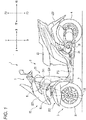
- the leaning vehicle 1 includes a vehicle main body 2, two front wheels 3, a rear wheel 4, a link mechanism 5 and a steering mechanism 6.
- the vehicle main body 2 includes a body frame 21, a vehicle body cover 22, a seat 23, a power unit 24, and a rear arm 25.
- Fig. 1 the body frame 21 is in an upright state.
- the following description to be made while referring to Fig. 1 is based on the premise that the body frame 21 is in the upright state.
- Fig. 1 is a left side view in which the whole of the leaning vehicle 1 is viewed from the left in the left-right direction of the body frame 21.
- the body frame 21 includes a head pipe 211 and a main frame 212.
- the head pipe 211 is disposed at a front portion of the leaning vehicle 1.
- an upper portion of the head pipe 211 is disposed ahead of a lower portion of the head pipe 211 in the front-rear direction of the body frame 21.
- the main frame 212 is connected to the head pipe 211.
- the main frame 212 is disposed behind the head pipe 211 in the front-rear direction of the body frame 21.
- the main frame 212 supports the seat 23, the power unit 24, and the rear arm 25.
- the power unit 24 comprises a power source such as an engine, an electric motor, a battery or the like and a transmission mechanism such as a transmission. A driving force generated by the drive source is transmitted to the rear wheel 4 by way of the transmission mechanism.
- the rear arm 25 extends in the front-rear direction of the body frame 21.
- a front end portion of the rear arm 25 is supported on the main frame 212 and is allowed to turn about an axis that extends in the left-right direction of the body frame 21.
- a rear end portion of the rear arm 25 supports the rear wheel 4.
- the body cover 22 is a body component that at least partially covers components that makes up the leaning vehicle 1.
- the vehicle body cover 22 includes a front cover 221, two front fenders 222, a rear fender 223, and a leg shield 224.
- the front cover 221 is disposed ahead of the seat 23 in the front-rear direction of the body frame 21.
- the front cover 221 covers the link mechanism 5 and at least part of the steering mechanism 6.
- the front cover 221 is disposed in such a manner as not to be displaced relative to the body frame 21.
- each of the front fenders 222 is disposed directly below the front cover 221. At least a portion of each of the two front fenders 222 is disposed above a corresponding front wheel 3.
- the two front wheels 3 are disposed below the head pipe 211 in an up-down direction of the body frame 21. At least portions of the two front wheels 3 are disposed directly below the front cover 221 in the up-down direction of the body frame 21.
- the rear wheel 4 is at least partially disposed below the seat 23 in the up-down direction of the body frame 21.
- the rear wheel 4 is at least partially disposed directly below the rear front fender 223 in the up-down direction of the body frame 21.
- the leg shield 224 is disposed behind the two front wheels 3 and ahead of the seat 23 in the front-rear direction of the body frame 21.
- the leg shield 224 is disposed in a position where the leg shield 224 at least partially covers the legs of the rider who sits on the seat 23 when viewed from the front of the leaning vehicle 1.
- Fig. 2 is a front view of a front portion of the leaning vehicle 1 as viewed from the front of the leaning vehicle 1 in the front-rear direction of the body frame 21.
- the body frame 21 is in the upright state.
- the following description to be made while referring to Fig. 2 is based on the premise that the body frame 21 is in the upright state.
- the front portion of the leaning vehicle 1 is illustrated as seen through the front cover 221, the two front fenders 222, and the leg shield 224 which are indicated by dashed lines.
- the two front wheels 3 include a left wheel 31 and a right wheel 32.
- the left wheel 31 is disposed on the left of the head pipe 211, which constitutes part of the body frame 21, in the left-right direction of the body frame 21.
- the right wheel 32 is disposed on the right of the head pipe 211 in the left-right direction of the body frame 21.
- the left wheel 31 and the right wheel 32 are arranged side by side in the left-right direction of the body frame 21.
- the two front fenders 222 include a left fender and a right fender.
- the left fender at least partially covers an upper face of the left wheel 31.
- the right fender at least partially covers an upper surface of the right wheel 32.
- the steering mechanism 6 includes a handlebar 61 and a steering shaft 62.
- the steering shaft 62 extends downwards from an intermediate portion of the handlebar 61 in relation to the left-right direction thereof.
- the steering shaft 62 is supported on the head pipe 211 via an intermediate steering bearing portion (not illustrated). As a result, the steering shaft 62 can turn around an intermediate steering axis SI relative to the head pipe 211.
- the link mechanism 5 adopts a parallel four-joint link (also referred to as a "parallelogram link").
- the link mechanism 5 is disposed above the left wheel 31 and the right wheel 32 in the up-down direction of the body frame 21.
- the link mechanism 5 includes an upper cross member 51, a lower cross member 52, a left side member 53, and a right side member 54.
- the link mechanism 5 is not interlocked with turning of the steering shaft 62 around the intermediate steering axis SI which is triggered when the handlebar 61 is operated. That is, the link mechanism 5 does not turn around the intermediate steering axis SI relative to the body frame 21.
- the head pipe 211 includes an upper intermediate leaning bearing portion 211a.
- An intermediate portion of the upper cross member 51 is supported on the head pipe 211 via the upper intermediate leaning bearing portion 211a.
- the upper cross member 51 can turn relative to the head pipe 211 around an upper intermediate leaning axis LUI that extends through the upper intermediate leaning bearing portion 211a in the front-rear direction of the body frame 21.
- the head pipe 211 includes a lower intermediate bearing portion 211b.
- An intermediate portion of the lower cross member 52 is supported on the head pipe 211 via the lower intermediate leaning bearing portion 211b.
- the lower cross member 52 can turn relative to the head pipe 211 around a lower intermediate leaning axis LDI that extends through the lower intermediate leaning bearing portion 211b in the front-rear direction of the body frame 21.
- the left side member 53 includes an upper left leaning bearing portion 53a.
- a left end portion of the upper cross member 51 is coupled to the left side member 53 via the upper left leaning bearing portion 53a.
- the upper cross member 51 can turn relative to the left side member 53 around an upper left leaning axis LULthat extends through the upper left leaning bearing portion 53a in the front-rear direction of the body frame 21.
- the right side member 54 includes an upper right leaning bearing portion 54a.
- a right end portion of the upper cross member 51 is coupled to the right side member 54 via the upper right leaning bearing portion 54a.
- the upper cross member 51 can turn relative to the right side member 54 around an upper right leaning axis LUR that extends through the upper right leaning bearing portion 54a in the front-rear direction of the body frame 21.
- the left side member 53 includes a lower left leaning bearing portion 53b.
- a left end portion of the lower cross member 52 is coupled to the left side member 53 via the lower left leaning bearing portion 53b.
- the lower cross member 52 can turn relative to the left side member 53 around a lower left leaning axis LDL that extends through the lower left leaning bearing portion 53b in the front-rear direction of the body frame 21.
- the right side member 54 includes a lower right leaning bearing portion 54b.
- a right end portion of the lower cross member 52 is coupled to the right side member 54 via the lower right leaning bearing portion 54b.
- the lower cross member 52 can turn relative to the right side member 54 around a lower right leaning axis LDR that extends through the lower right leaning bearing portion 54b in the front-rear direction of the body frame 21.
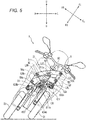
- Fig. 3 is a plan view of the front portion of the leaning vehicle 1 as viewed from above in the up-down direction of the body frame 21.
- the body frame 21 is in the upright state.
- the following description to be made while referring to Fig. 3 is based on the premise that the body frame 21 is in the upright state.
- the front portion of the leaning vehicle 1 is illustrated as seen through the front cover 221 and the two front fenders 222 that are indicated by dashed lines.
- the upper cross member 51 is disposed ahead of the head pipe 211 in the front-rear direction of the body frame 21.
- the upper cross member 51 is a plate-shaped member that extends in the left-right direction of the body frame 21 without being curved in the front-rear direction of the body frame 21.
- the lower cross member 52 is disposed below the upper cross member 51 in the up-down direction of the body frame 21.
- the lower cross member 52 includes a front element 521 and a rear element 522.
- the front element 521 is disposed ahead of the head pipe 211, the left side member 53 and the right side member 54 in the front-rear direction of the body frame 21.
- the rear element 522 is disposed behind the head pipe 211, the left side member 53 and the right side member 54 in the front-rear direction of the body frame 21.
- the front element 521 and the rear element 522 extend in the left-right direction of the body frame 21.
- the left side member 53 is disposed directly on the left of the head pipe 211 in the left-right direction of the body frame 21.
- the left side member 53 is disposed above the left wheel 31 in the up-down direction of the body frame 21.
- the left side member 53 extends in a direction in which the head pipe 211 extends.
- An upper portion of the left side member 53 is disposed behind a lower portion thereof in the front-rear direction of the body frame 21.
- the right side member 54 is disposed directly on the right of the head pipe 211 in the left-right direction of the body frame 21.
- the right side member 54 is disposed above the right wheel 32 in the up-down of the body frame 21.
- the right side member 54 extends in the direction in which the head pipe 211 extends.
- An upper portion of the right side member 54 is disposed behind a lower portion thereof in the front-rear direction of the body frame 21.
- the upper cross member 51, the lower cross member 52, the left side member 53 and the right side member 54 are supported on the head pipe 211 so that the upper cross member 51 and the lower cross member 52 are kept in a posture in which the upper cross member 51 and the lower cross member 52 are parallel to each other and that the left side member 53 and the right side member 54 are kept in a posture in which the left side member 53 and the right side member 54 are parallel to each other.
- the leaning vehicle 1 includes a left suspension unit 7.
- the left suspension unit 7 includes a left bracket 71 and a left shock absorbing device 72.
- the left bracket 71 includes a left turnable member (not illustrated) at an upper portion thereof.
- the left turnable member is disposed in an interior of the left side member 53 and extends in the same direction as a direction in which the left side member 53 extends.
- the left side member 53 includes a left steering bearing portion (not illustrated).
- the left turnable member is supported on the left side member 53 via the left steering bearing portion.
- the left turnable member can turn relative to the left side member 53 around a left steering axis SL. That is, the left bracket 71 is coupled to the left side member 53 in such a manner as to turn relative to the left side member 53 around the left steering axis SL.
- the left steering axis SL extends in the direction in which the left side member 53 extends. As illustrated in Fig. 2 , the left steering axis SL extends parallel to the intermediate steering axis SI of the steering shaft 62 in the up-down direction of the body frame 21. As illustrated in Fig. 3 , the left steering axis SL extends parallel to the intermediate steering axis SI of the steering shaft 62 in the front-rear direction of the body frame 21.
- the left shock absorbing device 72 is a so-called telescopic shock absorbing mechanism. As illustrated in Fig. 2 , the left shock absorbing device 72 includes a left upper telescopic element 721, a left lower telescopic element 722, and a left wheel axle 723.
- the left upper telescopic element 721 is supported on the left bracket 71.
- the left lower telescopic element 722 is coupled to the left upper telescopic element 721 in such a manner as to slide relative to the left upper telescopic element 721.
- a displacement of the left wheel 31 relative to the link mechanism 5 in the up-down direction of the body frame 21 is mitigated by the left lower telescopic element 722 sliding relative to the left upper telescopic element 721.
- the left wheel axle 723 is supported on the left lower telescopic element 722.
- the left wheel axle 723 supports the left wheel 31.
- the left wheel 31 can rotate around the left wheel axle 723.
- the leaning vehicle 1 includes a right suspension unit 8.
- the right suspension unit 8 includes a right bracket 81 and a right shock absorbing device 82.
- the right bracket 81 includes a right turnable member (not illustrated) at an upper portion thereof.
- the right turnable member is disposed in an interior of the right side member 54 and extends in the same direction as a direction in which the right side member 54 extends.
- the right side member 54 includes a right steering bearing portion (not illustrated).
- the right turnable member is supported on the right side member 54 via the right steering bearing portion.
- the right turnable member can turn relative to the right side member 54 around a right steering axis SR. That is, the right bracket 81 is coupled to the right side member 54 in such a manner as to turn relative to the right side member 54 around the right steering axis SR.
- the right steering axis SR extends in a direction in which the right side member 54 extends. As illustrated in Fig. 2 , the right steering axis SR extends parallel to the intermediate steering axis SI of the steering shaft 62 in the up-down direction of the body frame 21. As illustrated in Fig. 3 , the right steering axis SR extends parallel to the intermediate steering axis SI of the steering shaft 62 in the front-rear direction of the body frame 21.
- the right shock absorbing device 82 is a so-called telescopic shock absorbing mechanism. As illustrated in Fig. 2 , the right shock absorbing device 82 includes a right upper telescopic element 821, a right lower telescopic element 822, and a right wheel axle 823.
- the right upper telescopic element 821 is supported on the right bracket 81.
- the right lower telescopic element 822 is coupled to the right upper telescopic element 821 in such a manner as to slide relative to the right upper telescopic element 821.
- a displacement of the right wheel 32 relative to the link mechanism 5 in the up-down direction of the body frame 21 is mitigated by the right lower telescopic element 822 sliding relative to the right upper telescopic element 821.
- the right wheel axle 823 is supported on the right lower telescopic element 822.
- the right wheel axle 823 supports the right wheel 32.
- the right wheel 32 can rotate around the right wheel axle 823.
- the left steering axis SL is inclined rearwards in the front-rear direction of the body frame 21 from the vertical direction (in the up-down direction of the body frame 21), so that a caster angle is provided.
- the right steering axis SR is inclined rearwards in the front-rear direction of the body frame 21 from the vertical direction (in the up-down direction of the body frame 21), so that a caster angle is provided.
- a point of intersection between the left steering axis SL and a ground surface G is positioned ahead of a ground contact point LG of the left wheel 31 in the front-rear direction of the body frame 21, so that a positive caster trail is provided.
- a point of intersection between the right steering axis SR and the ground surface G is positioned ahead of a ground contact point of the right wheel 32 in the front-rear direction of the body frame 21, so that a positive caster trail is provided.
- a cross-sectional shape of a ground contact portion 31a of the left wheel 31 in a plane including the left wheel axle 723 is curved.
- a cross-sectional shape of a ground contact portion 32a of the right wheel 32 in a plane including the right wheel axle 823 is curved.
- the leaning vehicle 1 is configured such that the self-steering occurs.
- the left wheel 31 and the right wheel 32 attempt to turn in a direction indicated by an arrow LT in Fig. 4 around the left steering axis SL and the right steering axis SR, respectively.
- the left wheel 31 and the right wheel 32 attempt to turn in a direction indicated by an arrow RT in Fig. 4 around the left steering axis SL and the right steering axis SR, respectively.
- the leaning vehicle 1 includes a steering sensor 90.
- the steering sensor 90 is joined to the steering shaft 62.
- the steering sensor 90 detects a turning angle of the steering shaft 62 that corresponds to an operation of the handlebar 61 by a rider.
- Examples of the steering sensor 90a include a magnetostrictive sensor, a rotary encoder, a potentiometer, and the like.
- the leaning vehicle 1 includes a control unit 93.
- the control unit 93 includes a processor and a memory. Examples of the processor include a CPU, an MPU, and a GPU.
- the processor can include a plurality of processor cores. Examples of the memory include a ROM and a RAM.
- the ROM stores a program for executing the operations described above.
- the program can include an artificial intelligent program. Examples of the artificial intelligent program include a pretrained neural network based on deep learning.
- the processor can designate at least part of the program stored in the ROM, deploy it on the RAM, and execute the operations described above in cooperation with the RAM.
- the control unit 93 may be configured as a control device such as an ECU, may be configured by an integrated circuit such as an ASIC or an FPGA, or may be configured by a combination of a microcontroller and an integrated circuit.
- the control unit 93 is configured to communicate with the steering sensor 90.
- the steering sensor 90 inputs a signal corresponding to a turning angle of the steering shaft 62 that the steering sensor 90 detects to the control unit 93.
- the leaning vehicle 1 includes a steering actuator 91.
- the steering actuator 91 constitutes a device for generating a force to turn the left suspension unit 7 around the left steering axis SL and a force to turn the right suspension unit 8 around the right steering axis SR.
- the steering actuator 91 can be implemented with an electric motor or a hydraulic motor.
- the steering actuator 91 is configured to communicate with the control unit 93.
- the control unit 93 outputs a signal causing the steering actuator 91 to perform a desired operation based on the signal that is inputted thereto from the steering sensor 90.
- the steering mechanism 6 includes a steering force transmission mechanism 63.
- the steering actuator 91 is mechanically joined to the steering force transmission mechanism 63.
- the steering actuator 91 imparts a force to turn the left suspension unit 7 around the left steering axis SL and a force to turn the right suspension unit 8 around the right steering axis SR to the steering force transmission mechanism 63 based on the signal inputted thereto from the control unit 93.
- the steering force transmission mechanism 63 includes an intermediate transmission plate 631, a left transmission plate 632, a right transmission plate 633, an intermediate joint 634, a left joint 635, a right joint 636, and a tie rod 637.
- the intermediate transmission plate 631 is provided at a lower portion of the steering shaft 62.
- the intermediate transmission plate 631 can turn relative to the head pipe 211 around a turning axis that extends parallel to the intermediate steering axis SI of the steering shaft 62.
- the left transmission plate 632 is disposed directly on the left of the intermediate transmission plate 631.
- the left transmission plate 632 is connected to a lower portion of the left bracket 71.
- the left transmission plate 632 cannot turn relative to the left bracket 71.
- the left transmission plate 632 can turn relative to the left side member 53 around the left steering axis SL.
- the right transmission plate 633 is disposed directly on the right of the intermediate transmission plate 631 in the left-right direction of the body frame 21.
- the right transmission plate 633 is connected to a lower portion of the right bracket 81.
- the right transmission plate 633 cannot turn relative to the right bracket 81.
- the right transmission plate 633 can turn relative to the right side member 54 around the right steering axis SR.
- the intermediate joint 634 includes an intermediate joint steering bearing portion 634a.
- the intermediate joint steering bearing portion 634a defines an intermediate joint steering axis that extends in the up-down direction of the body frame 21.
- the intermediate joint 634 is coupled to a front portion of the intermediate transmission plate 631 via the intermediate joint steering bearing portion 634a. This enables the intermediate joint 634 to turn relative to the intermediate transmission plate 631 around the intermediate joint steering axis.
- the left joint 635 is disposed on the left of the intermediate joint 634 in the left-right direction of the body frame 21.
- the left joint 635 includes a left joint steering bearing portion 635a.
- the left joint steering bearing portion 635a defines a left joint steering axis that extends in the up-down direction of the body frame 21.
- the left joint 635 is coupled to a front portion of the left transmission plate 632 via the left joint steering bearing portion 635a. This enables the left joint 635 to turn relative to the left transmission plate 632 around the left joint steering axis.
- the right joint 636 is disposed on the right of the intermediate joint 634 in the left-right direction of the body frame 21.
- the right joint 636 includes a right joint steering bearing portion 636a.
- the right joint steering bearing portion 636a defines a right joint steering axis that extends in the up-down direction of the body frame 21.
- the right joint 636 is coupled to a front portion of the right transmission plate 633 via the right joint steering bearing portion 636a. This enables the right joint 636 to turn relative to the right transmission plate 633 around the right joint steering axis.
- the intermediate joint 634 includes an intermediate joint leaning bearing portion 634b.
- the intermediate joint leaning bearing portion 634b defines an intermediate joint leaning axis that extends in the front-rear direction of the body frame 21.
- An intermediate portion of the tie rod 637 is coupled to the intermediate joint leaning bearing portion 634b. The intermediate portion of the tie rod 637 can turn relative to the intermediate joint leaning bearing portion 634b around the intermediate joint leaning axis.
- the left joint 635 includes a left joint leaning bearing portion 635b.
- the left joint leaning bearing portion 635b defines a left joint leaning axis that extends in the front-rear direction of the body frame 21.
- a left portion of the tie rod 637 is coupled to the left joint leaning bearing portion 635b. The left portion of the tie rod 637 can turn relative to the left joint leaning bearing portion 635b around the left joint leaning axis.
- the right joint 636 includes a right joint leaning bearing portion 636b.
- the right joint leaning bearing portion 636b defines a right joint leaning axis that extends in the front-rear direction of the body frame 21.
- a right portion of the tie rod 637 is coupled to the right joint leaning bearing portion 636b. The right portion of the tie rod 637 can turn relative to the right joint leaning bearing portion 636b about the right joint leaning axis.
- the left transmission plate 632 is coupled to the intermediate transmission plate 631 via the left joint 635, the tie rod 637 and the intermediate joint 634.
- the right transmission plate 633 is coupled to the intermediate transmission plate 631 via the right joint 636, the tie rod 637 and the intermediate joint 634.
- the left transmission plate 632 and the right transmission plate 633 are coupled to each other via the left joint 635, the tie rod 637 and the right joint 636.
- the tie rod 637 couples the intermediate transmission plate 631 to the left transmission plate 632 and the right transmission plate 633.
- FIG. 4 is a plan view of the front portion of the leaning vehicle 1 as viewed from above in the up-down direction of the body frame 21 with the left wheel 31 and the right wheel 32 steered to turn to the left.
- the body frame 21 is in the upright state.
- the following description to be made while referring to Fig. 4 is based on the premise that the body frame 21 is in the upright state.
- the front portion of the leaning vehicle 1 is illustrated as seen through the front cover 221 and the two front fenders 222 that are indicated by dashed lines.
- the steering shaft 62 turns around the intermediate steering axis SI relative to the head pipe 211.
- the steering shaft 62 turns in a direction indicated by an arrow LT.
- the turning of the steering shaft 62 in the direction indicated by the arrow LT is detected by the steering sensor 90.
- the steering sensor 90 inputs a signal corresponding to the detected turning of the steering shaft 60 to the control unit 93.
- the control unit 93 causes the steering actuator 91 to perform an operation based on the signal inputted thereto.
- the intermediate transmission plate 631 turns around the intermediate steering axis SI relative to the head pipe 211 in the direction indicated by the arrow LT based on the operation performed by the steering actuator 91.
- the intermediate joint 634 of the tie rod 637 turns in a direction indicated by the arrow RT relative to the intermediate transmission plate 631 in association with the turning of the intermediate transmission plate 631 in the direction indicated by the arrow LT.
- the tie rod 637 moves to the left in the left-right direction of the body frame 21 and to the rear in the front-rear direction of the body frame 21 while maintaining its posture.
- the left joint 635 and the right joint 636 of the tie rod 637 turn in the direction indicated by the arrow RT relative to the left transmission plate 632 and the right transmission plate 633, respectively.
- the left transmission plate 632 and the right transmission plate 633 turn in the direction indicated by the arrow LT with the tie rod 637 maintaining its posture.
- the left bracket 71 which is not allowed to turn relative to the left transmission plate 632, turns in the direction indicated by the arrow LT around the left steering axis SL relative to the left side member 53.
- the right bracket 81 which is not allowed to turn relative to the right transmission plate 633, turns in the direction indicated by the arrow LT around the right steering axis SR relative to the right side member 54.
- the left shock absorbing device 72 When the left bracket 71 turns in the direction indicated by the arrow LT, the left shock absorbing device 72, which is supported on the left bracket 71, turns in the direction indicated by the arrow LT around the left steering axis SL relative to the left side member 53.
- the left shock absorbing device 72 turns in the direction indicated by the arrow LT
- the left wheel 31, which is supported on the left shock absorbing device 72 via the left wheel axle 723 turns in the direction indicated by the arrow LT around the left steering axis SL relative to the left side member 53.
- the left fender also turns in the direction indicated by the arrow LT together with the left wheel 31.
- the right shock absorbing device 82 When the right bracket 81 turns in the direction indicated by the arrow LT, the right shock absorbing device 82, which is supported on the right bracket 81, turns in the direction indicated by the arrow LT around the right steering axis SR relative to the right side member 54.
- the right shock absorbing device 82 turns in the direction indicated by the arrow LT
- the right wheel 32 which is supported on the right shock absorbing device 82 via the right wheel axle 823, turns in the direction indicated by the arrow LT around the right steering axis SR relative to the right side member 54.
- the right fender also turns in the direction indicated by the arrow LT together with the right wheel 32.
- the elements described above turn in an opposite direction to the direction in which they turn when the left and right front wheels are steered to turn to the left. Since the elements move simply in the opposite directions in the left-right direction, a detailed description of the movements of the elements when the rider so operates the handlebar 61 will be omitted here.
- the steering force transmission mechanism 63 couples the left suspension unit 7 and the right suspension unit 8 together and turns the left wheel 31 and the right wheel 32 in the direction in which the handlebar 61 is turned.
- a signal corresponding to the turning of the handlebar 61 is inputted from the control unit 93 to the steering actuator 91.
- the steering actuator 91 imparts a force to turn the left suspension unit 7 around the left steering axis SL and a force to turn the right suspension unit 8 around the right steering axis SR to the steering force transmission mechanism 63.
- a signal enabling a steady cornering in which the steering angles of the left wheel 31 and the right front wheel 32 are maintained is inputted from the control unit 93 to the steering actuator 91.
- the steering actuator 91 imparts forces to turn the left suspension unit 7 and the right suspension unit 8 around the left steering axis SL and the right steering axis SR, respectively, in the direction indicated by the arrow RT to the steering force transmission mechanism 63. This enables the steady cornering.
- FIG. 5 is a front view of the front portion of the leaning vehicle 1 as viewed from the front in the front-rear direction of the body frame 21, with the body frame 21 caused to lean to the left of the leaning vehicle 1.
- the front portion of the leaning vehicle 1 is illustrated as seen through the front cover 221, the two front fenders 222, and the leg shield 224 that are indicated by dashed lines.
- the link mechanism 5 when the leaning vehicle 1 is viewed from the front of the body frame 21 in the upright state, the link mechanism 5 exhibits a rectangle shape. As illustrated in Fig. 9 , when the leaning vehicle 1 is viewed from the front of the body frame 21 with the leaning vehicle 1 in a leaned state, the link mechanism 5 exhibits a parallelogram shape. The operation of the link mechanism 5 is interlocked with the leaning of the body frame 21 in the left-right direction thereof.
- the "operation of the link mechanism 5" means a change in the shape of the link mechanism 5 as a result of the upper cross member 51 and the lower cross member 52 turning relative to the head pipe 211 about the upper intermediate leaning axis LUI and the lower intermediate leaning axis LDI, respectively, and the upper cross member 51, the lower cross member 52, the left side member 53 and the right side member 54 turning relatively about the upper left leaning axis LUL, the upper right leaning axis LUR, the lower left leaning axis LDL and the lower right leaning axis LDR, respectively.
- the head pipe 211 leans to the left relative to or from the vertical direction.
- the upper cross member 51 turns counterclockwise relative to the head pipe 211 around the upper intermediate leaning axis LUI that passes through the upper intermediate leaning bearing portion 211a when the leaning vehicle 1 is viewed from the front thereof.
- the lower cross member 52 turns counterclockwise relative to the head pipe 211 around the lower intermediate leaning axis LDI that passes through the lower intermediate leaning bearing portion 211b when the leaning vehicle 1 is viewed from the front thereof.
- the upper cross member 51 moves to the left in the left-right direction of the body frame 21 relative to the lower cross member 52.
- the upper cross member 51 moves in the way described above, the upper cross member 51 turns counterclockwise around the upper left leaning axis LUL that passes through the upper left leaning bearing portion 53a and the upper right leaning axis LUR that passes through the upper right leaning bearing portion 54a relative to the left side member 53 and the right side member 54, respectively, when the leaning vehicle 1 is viewed from the front thereof.
- the lower cross member 52 turns counterclockwise around the lower left leaning axis LDL that passes through the lower left leaning bearing portion 53b and the lower right leaning axis LDR that passes through the lower right leaning bearing portion 54b relative to the left side member 53 and the right side member 54, respectively, when the leaning vehicle 1 is viewed from the front thereof.
- the left side member 53 and the right side member 54 lean to the left of the leaning vehicle 1 from the vertical direction while maintaining their postures parallel to the head pipe 211.
- the lower cross member 52 moves to the left in the left-right direction of the body frame 21 relative to the tie rod 637.
- the tie rod 637 turns relative to the intermediate joint 634, the left joint 635, and the right joint 636 around the intermediate joint leaning bearing portion 634b, the left joint leaning bearing portion 635b, and the right joint leaning bearing portion 636b, respectively.
- the tie rod 637 keeps its posture parallel to the upper cross member 51 and the lower cross member 52.
- the left bracket 71 which is supported on the left side member 53 via the left turnable member, leans to the left of the leaning vehicle 1 as the left side member 53 leans to the left of the leaning vehicle 1.
- the left shock absorbing device 72 which is supported on the left bracket 71, also leans to the left of the leaning vehicle 1.
- the left wheel 31 supported on the left shock absorbing device 72 leans to the left of the leaning vehicle 1 while maintaining its posture parallel to the head pipe 211.
- the right bracket 81 which is supported on the right side member 54 via the right tunable member, leans to the left of the leaning vehicle 1 as the right side member 54 leans to the left of the leaning vehicle 1.
- the right shock absorbing device 82 which is supported on the right bracket 81, also leans to the left of the leaning vehicle 1.
- the right wheel 32 which is supported on the right shock absorbing device 82, leans to the left of the leaning vehicle 1 while maintaining its posture parallel to the head pipe 211.
- the leaning operations of the left wheel 31 and the right wheel 32 are described based on the vertical direction. However, when the leaning vehicle 1 leans (when the link mechanism 5 is in operation), the up-down direction of the body frame 21 does not coincide with the vertical up-down direction. In the case where the leaning operation of the left wheel 31 and the right wheel 32 is described based on the up-down direction of the body frame 21, when the link mechanism 5 is in operation, the relative positions of the left wheel 31 and the right front wheel 32 are changed in the up-down direction of the body frame 21. In other words, the link mechanism 5 changes the relative positions of the left wheel 31 and the right wheel 32 in the up-down direction of the body frame 21 to thereby cause the body frame 21 to lean leftward or rightward from the vertical direction. This causes the leaning vehicle 1 to turn to the left.
- Fig. 6 is a front view of the front portion of the leaning vehicle 1 when viewed from the front in the front-and rear direction of the body frame 21 with the leaning vehicle 1 leaned leftward and steered to the left.
- Fig. 6 illustrates the front portion of the leaning vehicle 1 as seen through the front cover 221 and the two front fenders 222 that are illustrated by dashed lines.
- the left wheel 31 is turned counterclockwise around the left steering axis SL, while the right wheel 32 is turned counterclockwise around the right steering axis SR.
- the left wheel 31 and the right wheel 32 lean to the left of the leaning vehicle 1 together with the body frame 21 as a result of the leaning operation being performed. That is, in this state, the link mechanism 5 is exhibiting the parallelogram shape.
- the tie rod 637 has moved to the left in the left-right direction of the body frame 21 and to the rear in the front-rear direction of the body frame 21 from the position of the tie rod 637 at which the body frame 21 is in the upright state.
- the leaning vehicle 1 includes a leaning actuator 92.
- the leaning actuator 92 constitutes a device for imparting a force to lean the body frame 21 leftward or rightward to the link mechanism 5.
- the leaning actuator 92 can be implemented with an electric motor or a hydraulic motor.
- the leaning actuator 92 imparts forces to turn the upper cross member 51 and the lower cross member 52 clockwise relative to the head pipe 211, the left side member 53, and the right side member 54 to the link mechanism 5.
- the leaning actuator 92 imparts forces to turn the upper cross member 51 and the lower cross member 52 counterclockwise relative to the head pipe 211, the left side member 53, and the right side member 54 to the link mechanism 5 with the body frame 21 leaning more to the left of the leaning vehicle 1.
- the leaning angle of the body frame 21 can be controlled appropriately.
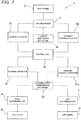
- the control unit 93 is connected to the steering actuator 91 and the leaning actuator 92.
- the control unit 93 can control the operation of the steering actuator 91 and the operation of the leaning actuator 92.
- the control unit 93 controls the operation of the steering actuator 91 and the operation of the leaning actuator 92 in cooperation with the steering mechanism 6 to thereby control the leaning angle of the body frame 21 leftward or rightward.
- the control unit 93 causes the steering actuator 91 to impart forces to turn the left suspension unit 7 and the right suspension unit 8 in the direction indicated by the arrow LT around the left steering axis SL and the right steering axis SR, respectively, to the steering mechanism 6.
- the control unit 93 causes the leaning actuator 92 to impart forces to turn the upper cross member 51 and the lower cross member 52 clockwise relative to the head pipe 211, the left side member 53 and the right side member 54 to the link mechanism 5.
- the leaning angle of the body frame 21 is adjusted to a desired angle.
- Loads that are generated on the steering actuator 91 and the leaning actuator 92 can be reduced since these actuators perform the operations described above in cooperation with each other.
- the control unit 93 can select two operation modes.
- the two operation modes include a first mode and a second mode.
- the first mode is a mode where the operations described above are performed. That is, the control unit 93 employs both the steering actuator 91 and the leaning actuator 92 to control the leaning angle of the body frame 21 leftward or rightward.
- the control unit 93 does not employ the leaning actuator 92 but employs the steering actuator 91 to control the leaning angle of the body frame 21 leftward or rightward.
- the leaning actuator 92 is placed in a rest state while the second mode is selected by the control unit 93.
- the first mode is based on a linked operation between the steering actuator 91 and the leaning actuator 92.
- the operation frequency of each of the actuators tends to be increased. Consequently, heat is generated in the actuators, and hence, countermeasures against the heat so generated need to be taken.
- the leaning vehicle 1 includes an auxiliary leaning actuator 92a.
- the auxiliary actuator 92a has the same configuration as that of the leaning actuator 92.
- the auxiliary actuator 92a is connected to the control unit 93.
- the auxiliary leaning actuator 92a is provided based on the countermeasure approach (2) described above. That is, in the event where the leaning actuator 92 happens to be not able to perform the desired operation, the control unit 93 stops controlling the operation of the leaning actuator 92 and causes the auxiliary leaning actuator 92a to perform the desired operation instead.
- Fig. 9A illustrates an example of an operation when the control unit 93 transits from the first mode to the second mode.
- a solid line denotes a relationship between an output of the steering actuator 91 and a temperature of the leaning actuator 92 for controlling the leaning angle of the body frame 21.
- a chain line denotes a relationship between an output of the leaning actuator 92and a temperature of the leaning actuator 92 for controlling the leaning angle of the body frame 21.
- the control unit 93 monitors heat generated by the leaning actuator 92 with a temperature sensor (not illustrated).
- a monitoring target may be a temperature of the leaning actuator 92 itself or a temperature at an appropriate location that correlates with heat from the leaning actuator 92.
- the control unit 93 starts a transition from the first mode to the second mode. Specifically, the control unit 93 decreases the output of the leaning actuator 92 non-stepwise to zero as the temperature detected by the temperature sensor increases. On the other hand, the control unit 93 increases the output of the steering actuator 91 non-stepwise up to a predetermined higher value.
- the leaning actuator 92 is placed in the rest state, whereby the transition to the second mode is completed.
- the heat from the leaning actuator 92 decreases, on the contrary, a transition from the second mode to the first mode is performed.
- a transition between the first mode and the second mode is performed in such a manner that the output of the leaning actuator 92 configured to control the leaning angle of the body frame 21 takes a value between a value taken before the transition and a value taken after the transition.
- the outputs of the steering actuator 91 and the leaning actuator 92 in the first mode coincide with each other.
- the outputs of the steering actuator 91 and the leaning actuator 92 in the first mode can individually be set at appropriate values.
- Fig. 9B illustrates another example of an operation performed when the control unit 93 transits from the first mode to the second mode.
- a solid line denotes a relationship between an output of the steering actuator 91 and a temperature of the leaning actuator 92 for controlling the leaning angle of the body frame 21.
- a chain line denotes a relationship between an output of the leaning actuator 92 and a temperature of the leaning actuator 92 for controlling the leaning angle of the body frame 21.
- the control unit 93 monitors heat generated by the leaning actuator 92 with a temperature sensor (not illustrated).
- a monitoring target may be a temperature of the leaning actuator 92 itself or a temperature at an appropriate location that correlates with heat from the leaning actuator 92.
- the control unit 93 executes a transition from the first mode to the second mode. Specifically, the control unit 93 switches the output of the leaning actuator 92 to zero. On the other hand, the control unit 93 switches the output of the steering actuator 91 to a predetermined higher value. As a result, the leaning actuator 92 is placed in the rest state. When the heat from the leaning actuator 92 decreases, on the contrary, a transition from the second mode to the first mode is performed.
- the transition between the first mode and the second mode is performed without causing the output of the leaning actuator 92 for controlling the leaning angle of the body frame 21 to take a value between the value before the transition and the value after the transition.
- a smooth transition between the first mode and the second mode can be provided even when the leaning vehicle 1 takes a quick and sharp turn.
- a time required until the leaning actuator is placed in the rest state can be shortened, the consumption of electric power and the generation of heat can be suppressed further. Suppressing the consumption of electric power contributes to miniaturization of a battery to be mounted on the leaning vehicle 1 as well as expansion of driving range.
- the outputs of the steering actuator 91 and the leaning actuator 92 in the first mode coincide with each other.
- the outputs of the steering actuator 91 and the leaning actuator 92 in the first mode can individually be set at appropriate values.
- the output never takes two values simultaneously. Consequently, from a microscopic point of view, there exists a moment when the output of the leaning actuator 92 takes a value between the output in the mode before the transition and the output in the mode after the transition.
- the expression reading, "without taking a value between the value before the transition and the value after the transition” means that the output is switched over between the two values without positively taking a value between the value before the transition and the value after the transition on a substantial control time scale. Consequently, in the example illustrated in Fig. 9A , the value of the output may be varied stepwise so as to positively take a value between the value before the transition and the value after the transition.
- the control unit 93 can further select a third mode.
- the control unit 93 does not employ the steering actuator 91 but employs the leaning actuator 92 to control the leaning angle of the body frame 21 leftward or rightward.
- the steering actuator 91 is placed in the rest state while the third mode is selected by the control unit 93.
- the leaning vehicle 1 includes an auxiliary steering actuator 91a.
- the auxiliary steering actuator 91a has the same configuration as that of the steering actuator 91.
- the auxiliary steering actuator 91a is connected to the control unit 93.
- the auxiliary steering actuator 91a is provided based on the countermeasure approach (2) described above. That is, in the event where the steering actuator 91 happens to be not able to perform the desired operation, the control unit 93 stops controlling the operation of the steering actuator 91 and causes the auxiliary steering actuator 91a to perform the desired operation instead.
- a more flexible mode selection in accordance with the conditions of the steering actuator 91 and the leaning actuator 92 can be realized by the fact that the third mode is selectable in addition to the first mode and the second mode.
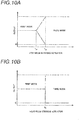
- Fig. 10A illustrates an example of an operation when the control unit 93 transits from the first mode to the third mode.
- a solid line denotes a relationship between an output of the steering actuator 91 and a temperature of the steering actuator 91 for controlling the leaning angle of the body frame 21.
- a chain line denotes a relationship between an output of the leaning actuator 92 and a temperature of the steering actuator 91 for controlling the leaning angle of the body frame 21.
- the control unit 93 monitors heat generated by the steering actuator 91 with a temperature sensor (not illustrated).
- a monitoring target may be a temperature of the steering actuator 91 itself or a temperature at an appropriate location that correlates with heat from the steering actuator 91.
- the control unit 93 starts a transition from the first mode to the third mode. Specifically, the control unit 93 decreases the output of the steering actuator 91 non-stepwise to zero as the temperature detected by the temperature sensor increases. On the other hand, the control unit 93 increases the output of the leaning actuator 92 non-stepwise up to a predetermined higher value.
- the steering actuator 91 is placed in the rest state, whereby the transition to the third mode is completed.
- the heat from the steering actuator 91 decreases, on the contrary, a transition from the third mode to the first mode is performed.
- a transition between the first mode and the third mode is performed in such a manner that the output of the steering actuator 91 configured to control the leaning angle of the body frame 21 takes a value between a value taken before the transition and a value taken after the transition.
- the outputs of the steering actuator 91 and the leaning actuator 92 in the first mode coincide with each other.
- the outputs of the steering actuator 91 and the leaning actuator 92 in the first mode can individually be set at appropriate values.
- Fig. 10B illustrates another example of an operation performed when the control unit 93 transits from the first mode to the third mode.
- a solid line denotes a relationship between an output of the steering actuator 91 and a temperature of the steering actuator 91 for controlling the leaning angle of the body frame 21.
- a chain line denotes a relationship between an output of the leaning actuator 92 and a temperature of the steering actuator 91 for controlling the leaning angle of the body frame 21.
- the control unit 93 monitors heat generated by the steering actuator 91 with a temperature sensor (not illustrated).
- a monitoring target may be a temperature of the steering actuator 91 itself or a temperature at an appropriate location that correlates with heat from the steering actuator 91.
- the control unit 93 starts a transition from the first mode to the third mode. Specifically, the control unit 93 switches the output of the steering actuator 91 to zero. On the other hand, the control unit 93 switches the output of the leaning actuator 92 to a predetermined higher value. As a result, the steering actuator 91 is placed in the rest state. When the heat from the steering actuator 91 decreases, on the contrary, a transition from the third mode to the first mode is performed.
- the transition between the first mode and the third mode is performed without causing the output of the steering actuator 91 for controlling the leaning angle of the body frame 21 to take a value between the value before the transition and the value after the transition.
- a smooth transition between the first mode and the third mode can be provided even when the leaning vehicle 1 takes a quick and sharp turn.
- the consumption of electric power and the generation of heat can be suppressed further. Suppressing the consumption of electric power contributes to miniaturization of a battery to be mounted on the leaning vehicle 1 as well as expansion of driving range.
- the outputs of the steering actuator 91 and the leaning actuator 92 in the first mode coincide with each other.
- the outputs of the steering actuator 91 and the leaning actuator 92 in the first mode can individually be set at appropriate values.
- the output never takes two values simultaneously. Consequently, from a microscopic point of view, there exists a moment when the output of the leaning actuator 92 takes a value between the output in the mode before the transition and the output in the mode after the transition.
- the expression reading, "without taking a value between the value before the transition and the value after the transition” means that the output is switched over between the two values without positively taking a value between the value before the transition and the value after the transition on a substantial control time scale. Consequently, in the example illustrated in Fig. 10A , the value of the output may be varied stepwise so as to positively take a value between the value before the transition and the value after the transition.
- control unit 93 selects any one of the first mode, the second mode, and the third mode based on the heat that the steering actuator 91 generates and the heat that the leaning actuator 92 generates.
- the parameters that are referred to as the reference for mode transitions are not limited to the heat that the steering actuator 91 generates and the heat that the leaning actuator 92 generates.
- Appropriate parameters that can reflect the operation frequencies of the steering actuator 91 and the leaning actuator 92 can be referred to as the reference for mode transition.
- a value of voltage applied to the steering actuator 91, a value of electric current that flows to the steering actuator 91, a value of voltage applied to the leaning actuator 92, and a value of electric current that flows to the leaning actuator 92 can be exemplified for such parameters.
- the control unit 93 may be configured to enable at least the transition between the first mode and the second mode as well as the transition between the first mode and the third mode.
- control unit 93 may be configured to permit a direct transition between the second mode and the third mode.
- the transitions among the first mode, the second mode, and the third mode may be configured to permit all permutations thereof.
- Fig. 11 illustrates an example of a case where such transitions are performed.
- a solid line denotes a chronological change in heat that the steering actuator 91 generates.
- a chain line denotes a chronological change in heat that the leaning actuator 92 generates.
- the transition between the second mode and the third mode can be performed in such a manner that the output of the steering actuator 91 and the output of the leaning actuator 92 for controlling the leaning angle of the body frame 21 take values between the values in the second mode and the values in the third mode.
- the values of the outputs may be varied non-stepwise or stepwise.
- the transition between the second mode and the third mode can be performed in such a manner that the output of the steering actuator 91 and the output of the leaning actuator 92 for controlling the leaning angle of the body frame 21 do not take values between the second mode and the third mode.
- the leaning vehicle 1 includes the auxiliary steering actuator 91a and the auxiliary leaning actuator 92a.
- at least one of the auxiliary steering actuator 91a and the auxiliary leaning actuator 92a can be omitted. That is, at least one of the steering actuator 91 and the leaning actuator 92 can be implemented with a single actuator.
- the auxiliary actuator for performing a backup operation can be made unnecessary. Accordingly, an increase in space that is occupied by the actuators can be suppressed, whereby an enlargement in size of the vehicle body can be suppressed.
- the leaning vehicle 1 can include a leaning restriction mechanism 94.
- the leaning restriction mechanism 94 is a mechanism for restricting the operation of the link mechanism 5.
- the leaning restriction mechanism 94 may be a mechanism for imparting a resisting force to a relative turning between the upper cross member 51 or the lower cross member 52 and the head pipe 211, or a mechanism for preventing the relative turning therebetween.
- a plate-shaped member may be provided on the upper cross member 51 or the lower cross member 52, and a caliper device that can grip on the plate-shaped member may be provided on the head pipe 211.
- the relative turning of the upper cross member 51 or the lower cross member 52 and the head pipe 211 can be restrained or prevented by causing the caliper device to grip the plate-shaped member at a required timing.
- control unit 93 may be configured to cause the leaning restriction mechanism 94 to restrict the operation of the link mechanism 5 while the second mode is being selected.
- a change in posture of the body frame 21 can be restricted when the second mode is selected in which the leaning actuator 92 is not employed.
- the consumption of electric power by and the generation of heat in the leaning actuator 92 can be suppressed, even though the posture of the body frame 21 can easily be maintained when the leaning vehicle 1 is traveling at low speeds, the rider walks while pushing the leaning vehicle 1, or the leaning vehicle 1 comes to a halt. Suppressing the consumption of electric power contributes to miniaturization of a battery to be mounted on the leaning vehicle 1 as well as expansion of driving range.
- the leaning vehicle 1 includes the two front wheels 3. According to this configuration, the link mechanism 5 and the leaning actuator 92 can be disposed closer to the front end of the leaning vehicle 1. As a result, since the leaning actuator 92 is easily subjected to running air, the requirement in relation to heat can be mitigated. Consequently, the necessity of employing a large leaning actuator with a large heat capacity can be suppressed, thereby suppressing the enlargement of the vehicle body.
- the leaning vehicle includes one front wheel and two rear wheels.
- the one front wheel needs to be a wheel to be steered.
- the handlebar 61 is made up of the single member that extends in the left-right direction of the body frame.
- the handlebar 61 may be made up of individual members including a left handlebar portion configured to be operated by the left hand of the rider and a right handlebar portion configured to be operated by the right hand of the rider, provided that steering force to turn the left wheel 31 and the right wheel 32 can be inputted through the handlebar 61.
- the handlebar 61 may take a form of a steering wheel or a steering rod.
- the link mechanism 5 comprises a cross member other than the upper cross member 51 and the lower cross member 52.
- the "upper cross member” and the “lower cross member” are merely so called based on their relative positional relationship in the up-down direction.
- the upper cross member does not mean an uppermost cross member in the link mechanism 5.
- the upper cross member means a cross member which lies above another cross member which lies therebelow.
- the lower cross member does not mean a lowermost cross member in the link mechanism 5.
- the lower cross member means a cross member which lies below another cross member which lies thereabove.
- the link mechanism 5 includes the so-called parallel four-joint link system. Namely, the upper cross member 51, the lower cross member 52, the left side member 53 and the right side member 54 are supported on the body frame 21 so that the upper cross member 51 and the lower cross member 52 are kept in a posture in which the upper cross member 51 and the lower cross member 52 are parallel to each other and that the left side member 53 and the right side member 54 are kept in a posture in which the left side member 53 and the right side member 54 are parallel to each other.
- a so-called double wishbone-type link mechanism can be adopted, provided that the body frame 21 can be caused to lean leftward or rightward by changing the relative positions of the left wheel 31 and the right wheel 32 to the body frame 21.
- control unit 93 is provided as an individual member from the steering actuator 91 and the leaning actuator 92.
- a configuration for realizing at least part of the function of the control unit 93 can be provided integrally with at least one of the steering actuator 91 and the leaning actuator 92.
- control unit 93 is described as being able to select the third mode in addition the basic configuration in which the control unit 93 can select the first mode and the second mode.
- a control unit can also be adopted in which the control unit can select the second mode in addition to a basic configuration in which the control unit can select the first mode and the third mode.
- the word “parallel” means that two straight lines which do not intersect each other as members while they are inclined at an angle falling within the range of ⁇ 40 degrees are comprised therein.
- the expression reading "along a certain direction” means that a case where something inclines at an angle falling within the range of ⁇ 40 degrees relative to the certain direction is comprised therein.
- the expression reading "something extends in a certain direction” means that a case where something extends while being inclined at an angle falling within the range of ⁇ 40 degrees relative to the certain direction is comprised therein.
- the expression “so as not to be movable relative to the body frame 21” means that a certain part or member is caused to lean in the left-right direction of the leaning vehicle 1 together with the body frame 21 when the body frame 21 is caused to lean in the left-right direction of the leaning vehicle 1.
- the expression “so as not to be movable relative to the body frame 21” may comprehend not only a case where a certain part or member is directly fixed to the body frame but also a case where the certain part of member is fixed to a leaning vehicle component (a fuel tank, a bracket, the power unit 24, etc.) which is fixed on the body frame 21.
- the term “fixed” may comprehend a case that a certain part or member is fixed by way of a damping member or the like.
- the disclosed concept can be implemented with many different embodiments. This description should be understood to provide a principle embodiment of the disclosed concept. The preferred embodiment which is at least described or illustrated in this description is so described or illustrated based on the understanding that the embodiment is not intended to limit the disclosed concept.
- the disclosed concept comprehends every embodiment which comprises an equivalent element, a modification, a deletion, a combination (for example, a combination of characteristics of various embodiments), an improvement and an alteration which can be recognized by those skilled in the art based on the embodiment disclosed in this description.
- the limitative matters of claims should be construed widely based on terms used in the claims and hence should not be limited by the embodiment described in this specification or the prosecution of this patent application.
- Those embodiments should be construed as non-exclusive.
- the terms “preferable” and “may” should be construed as being non-exclusive, and those terms mean, respectively, that it is “preferable but not limited thereto” and that it “may be acceptable but not limited thereto.”
Landscapes
- Engineering & Computer Science (AREA)
- Mechanical Engineering (AREA)
- Automatic Cycles, And Cycles In General (AREA)
Abstract
Description
- The presently disclosed subject matter relates to a leaning vehicle equipped with a leanable body frame and at least three wheels including a left wheel and a right wheel that are arranged side by side in a left-right direction of the body frame.
-
PTL 1 discloses an example of a leaning vehicle of this type. The leaning vehicle is equipped with the leanable body frame and the two front wheels that are arranged side by side in the left-right direction of the body frame. When this leaning vehicle is leaned leftward, the two front wheels attempt to turn counterclockwise as viewed from above the leaning vehicle. When this leaning vehicle is leaned rightward, the two front wheels attempt to turn clockwise as viewed from above the leaning vehicle. This phenomenon is referred to as self-steering. While the leaning vehicle is turning, a steering angle is generated in the front wheels as the body frame leans, and a state where the leaning of the body frame is balanced with a centrifugal force generated during the turning is maintained. When the directions of the front wheels are changed from this balanced state, the centrifugal force changes, whereby the leaning angle of the leaning vehicle can be changed. This will be true with a case where the leaning vehicle travels straight ahead. - Conditions where self-steering occurs are as follows:
- (1) A steering axis of each front wheel is inclined rearwards in a front-rear direction of the body frame relative to the vertical direction (a caster angle is provided);
- (2) A point of intersection between the steering axis of each front wheel and a ground surface is positioned ahead of a ground contact point of the relevant front wheel in the front-rear direction of the body frame (a positive caster trail is provided); and
- (3) A cross-sectional shape of a ground contact portion of each front wheel in a plane including a wheel axle of the relevant front wheel is curved.
- The leaning vehicle includes a suspension unit for supporting each front wheel. The leaning vehicle includes a steering mechanism for turning each suspension unit around the corresponding steering axis. The leaning vehicle includes a steering actuator configured to impart a force to turn each suspension unit around the corresponding steering axis to the steering mechanism.
- The leaning vehicle includes a link mechanism. The link mechanism is configured to lean the body frame to the left or the right by changing the relative positions of the two front wheels to the body frame. The leaning vehicle includes a leaning actuator configured to impart a force to lean the body frame leftward or rightward to the link mechanism.
- The leaning vehicle includes a control unit. The control unit controls the leaning angle of the body frame in cooperation with the steering mechanism by use of both the steering actuator and the leaning actuator. For example, when the leaning vehicle is attempted to be leaned leftward, the control unit causes the steering actuator to output torque to turn the two front wheels counterclockwise and the leaning actuator to output torque to restrain the body frame from turning to the left. In this specification, the approach of controlling the leaning angle of the body frame to the left or the right by use of both the steering actuator and the leaning actuator in the way described above is referred to as a "cooperative control".
- [PTL 1] International Publication
WO 2017/086403 - The cooperative control is based on a linked operation between the steering actuator and the leaning actuator. As a result, the operation frequency of each of the actuators tends to be increased. Consequently, heat is generated in the actuators, and hence, countermeasures against the heat so generated need to be taken.
- As countermeasures to be taken, the following approaches are considered: (1) high specifications are imparted to the actuators; and (2) actuators configured to back up the relevant actuators are prepared separately to deal with a case where the relevant actuators are prevented from performing the desired operations. However, these countermeasure approaches both result in an increase in the space occupied by the actuators and hence in an enlargement in size of the vehicle body.
- Consequently, in the leaning vehicle including the leanable body frame and at least three wheels including the left front wheel and the right front wheel that are arranged side by side in the left-right direction of the body frame, it is required to suppress an enlargement in size of the vehicle body while realizing a cooperative operation between the steering actuator and the leaning actuator.
- An illustrative aspect of the presently disclosed subject matter provides a leaning vehicle comprising:
- a body frame;
- at least three wheels including a left wheel and a right wheel that are arranged side by side in a left-right direction of the body frame;
- a suspension unit supporting a wheel that is included in the three wheels and a front wheel a cross sectional shape of which is curved; and
- a steering mechanism configured to turn the suspension unit about a steering axis,
- wherein the steering axis is inclined downward in a front-rear direction of the body frame relative to a vertical direction;
- wherein a cross point between the steering axis and a ground is located ahead of a ground contact point of the front wheel in the front-rear direction of the body frame;
- wherein a cross sectional shape of the ground contact point of the front wheel in a plane including an axle of the front wheel is curved;
- wherein the leaning vehicle further comprises:
- a link mechanism configured to change positions of the left wheel and the right wheel relative to the body frame to cause the body frame to lean leftward when the leaning vehicle is steered leftward and to cause the body frame to lean rightward when the leaning vehicle is steered rightward;
- a steering actuator configured to impart a force causing the suspension unit to turn about the steering axis to the steering mechanism;
- a leaning actuator configured to impart a force causing the body frame to lean leftward or rightward to the link mechanism; and
- a control unit capable of selecting a first mode in which both of the steering actuator and the leaning actuator are employed, and a second mode in which the steering actuator is employed without employing the leaning actuator, in order to control a leaning angle of the body frame in cooperation with the steering mechanism.
- According to such a configuration, since an operation state where at least the leaning actuator is at rest (the second mode) can be realized, specifications required on the leaning actuator can be mitigated. Thus, an enlargement in size of the vehicle body can be suppressed while realizing the cooperative control (the first mode) between the steering actuator and the leaning actuator.
- The "resting operation state" means that one of the actuators is not able to operate while a relevant mode is being selected. For example, there may be a situation where the steering actuator and the leaning actuator are not in operation while the vehicle is traveling straight ahead with the first mode selected. However, this situation where both the actuators are not in operation constitutes a so-called standby state, where the actuators are ready to operate depending upon the state of the leaning vehicle. In this situation, both the actuators are not in the "resting operation state".
- The leaning vehicle may be configured such that the control unit is configured to perform a transition between the first mode and the second mode such that an output of the leaning actuator for controlling the leaning angle takes a value between a value taken before the transition and a value taken after the transition.
- According to such a configuration, it is possible to not only suppress uncomfortable feelings that would be given to the driver due to the transition between the first mode and the second mode but also to provide a smoother turning operation.
- The leaning vehicle may be configured such that the control unit is configured to perform a transition between the first mode and the second mode such that an output of the leaning actuator for controlling the leaning angle takes no value between a value taken before the transition and a value taken after the transition.
- According to this configuration, a smooth transition between the first mode and the second mode can be provided even when the leaning vehicle takes a quick and sharp turn. In addition, since a time required until the leaning actuator is placed in the rest state can be shortened, the consumption of electric power and the generation of heat can be suppressed further. Suppressing the consumption of electric power contributes to miniaturization of a battery to be mounted on the leaning vehicle as well as expansion of driving range.
- The leaning vehicle may be configured such that the leaning actuator is implemented with a single actuator.
- As a result of the specification requirements for the leaning actuator being mitigated, a leaning actuator for performing a backup operation can be made unnecessary. Accordingly, an increase in space that is occupied by the leaning actuator can be suppressed, whereby an enlargement in size of the vehicle body can be suppressed.
- The leaning vehicle may be configured such that the control unit is configured to select one of the first mode and the second mode based on heat generated from the leaning actuator.
- According to such a configuration, it is possible to provide a direct mode selection control that can realize better matching with the required heat countermeasures.
- The leaning vehicle may be configured such that the control unit is capable of selecting, in addition to the first mode and the second mode, a third mode in which the leaning actuator is employed without employing the steering actuator.
- According to such a configuration, since an operation state where the steering actuator is at rest (the third mode) can be realized, the specification requirements imposed on the steering actuator can be mitigated. Thus, an enlargement in size of the vehicle body can be suppressed while realizing the cooperative control (the first mode) between the steering actuator and the leaning actuator.
- The leaning vehicle may be configured such that the control unit is configured to perform a transition between the first mode and the third mode such that an output of the steering actuator for controlling the leaning angle takes a value between a value taken before the transition and a value taken after the transition.
- According to such a configuration, it is possible to not only suppress uncomfortable feelings that would be given to the driver due to the transition between the first mode and the third mode but also to provide a smoother turning operation.
- The leaning vehicle may be configured such that the control unit is configured to perform a transition between the first mode and the third mode such that an output of the steering actuator for controlling the leaning angle takes no value between a value taken before the transition and a value taken after the transition.
- According to this configuration, a smooth transition between the first mode and the third mode can be provided even when the leaning vehicle takes a quick and sharp turn. In addition, since a time required until the steering actuator is placed in the rest state can be shortened, the consumption of electric power and the generation of heat can be suppressed further. Suppressing the consumption of electric power contributes to miniaturization of a battery to be mounted on the leaning vehicle as well as expansion of driving range.
- The leaning vehicle may be configured such that the steering actuator is implemented with a single actuator.
- As a result of the specification requirements for the steering actuator being mitigated, a steering actuator for performing a backup operation can be made unnecessary. Accordingly, an increase in space that is occupied by the leaning actuator can be suppressed, whereby an enlargement in size of the vehicle body can be suppressed.
- The leaning vehicle may be configured such that the control unit is configured to select one of the first mode and the third mode based on heat generated from the steering actuator.
- According to such a configuration, it is possible to provide a direct mode selection control that can realize better matching with the required heat countermeasures.
- The leaning vehicle may be configured such that the control unit is configured to perform a mode transition among the first mode, the second mode, and the third mode so as to permit at least a mode transition between the first mode and the second mode, and a mode transition between the first mode and the third mode.
- In this case, it is possible to realize a selective transition to the second mode or the third mode from the first mode that is referred to as a basic mode, thereby enabling suppression of an increase in processing load of the control unit.
- Preferably, the control unit may be configured to perform the mode transition among the first mode, the second mode, and the third mode so as to permit all permutations thereof.
- In this case, a more flexible mode transition in accordance with the states of the steering actuator and the leaning actuator can be provided.
- The leaning vehicle may be configured so as to further comprise a leaning restriction mechanism configured to restrict an operation of the link mechanism, and such that the control unit is configured to cause the leaning restriction mechanism to restrict the operation of the link mechanism while the second mode is selected.
- According to this configuration, a change in posture of the body frame can be restricted when the second mode is selected in which the leaning actuator is not employed. As a result, the consumption of electric power by and the generation of heat in the leaning actuator can be suppressed, even though the posture of the body frame can easily be maintained when the leaning vehicle is traveling at low speeds, the rider walks while pushing the leaning vehicle, or the leaning vehicle comes to a halt. Suppressing the consumption of electric power contributes to miniaturization of a battery to be mounted on the leaning vehicle as well as expansion of driving range.
- The leaning vehicle may be configured such that the left wheel and the right wheel are front wheels.
- In the above embodiment, the leaning vehicle includes the two front wheels. According to this configuration, the link mechanism and the leaning actuator can be disposed closer to the front end of the leaning vehicle. As a result, since the leaning actuator is easily subjected to running air, the requirement in relation to heat can be mitigated. Consequently, the necessity of employing a large leaning actuator with a large heat capacity can be suppressed, thereby suppressing the enlargement of the vehicle body.
-
-
Fig. 1 is a left side view entirely illustrating a leaning vehicle according to one embodiment. -
Fig. 2 is a front view illustrating a front portion of the leaning vehicle ofFig. 1 . -
Fig. 3 is a plan view illustrating the front portion of the leaning vehicle ofFig. 1 . -
Fig. 4 is a plan view illustrating the front portion of the leaning vehicle ofFig. 1 when steering to the left is performed. -
Fig. 5 is a front view illustrating the leaning vehicle ofFig. 1 when leaning to the left is performed. -
Fig. 6 is a rear view illustrating the leaning vehicle ofFig. 1 when leaning to the left and steering to the left are performed. -
Fig. 7 is a diagram illustrating a functional configuration of the leaning vehicle ofFig. 1 ; -
Fig. 8 is a diagram illustrating mode transitions to be performed in the leaning vehicle ofFig. 1 ; -
Fig. 9A is a diagram illustrating a mode transition to be performed in the leaning vehicle ofFig. 1 ; -
Fig. 9B is a diagram illustrating a mode transition to be performed in the leaning vehicle ofFig. 1 ; -
Fig. 10A is a diagram illustrating a mode transition to be performed in the leaning vehicle ofFig. 1 ; -
Fig. 10B is a diagram illustrating a mode transition to be performed in the leaning vehicle ofFig. 1 ; and -
Fig. 11 is a diagram illustrating mode transitions to be performed in the leaning vehicle ofFig. 1 . - Referring to the accompanying drawings, an exemplary embodiment will be described in detail below.
- In the accompanying drawings, an arrow F denotes a front or forward direction of a leaning vehicle. An arrow B denotes a back/rear or backward/rearward direction of the leaning vehicle. An arrow U denotes an up or upward direction of the leaning vehicle. An arrow D denotes a down or downward direction of the leaning vehicle. An arrow R denotes a right or rightward direction of the leaning vehicle. An arrow L denotes a left or leftward direction of the leaning vehicle.
- A leaning vehicle turns with a body frame being caused to lean leftward or rightward from a vertical direction. Then, in addition to the directions based on the leaning vehicle, directions based on the body frame will be defined. In the accompanying drawings, an arrow FF denotes a front or forward direction of the body frame. An arrow FB denotes a back/rear or backward/rearward of the body frame. An arrow FU denotes an up or upward direction of the body frame. An arrow FD denotes a down or downward direction of the body frame. An arrow FR denotes a right or rightward direction of the body frame. An arrow FL denotes a left or leftward direction of the body frame.
- In this description, a "front-rear direction of the body frame," a "left-right direction of the body frame" and an "up-down direction of the body frame" mean a front-rear direction, a left-right direction and an up-down direction based on the body frame when viewed from a rider who rides the leaning vehicle. "A side of or sideways of the body frame" means directly on the right or left in the left-right direction of the body frame.
- In this description, an expression "extending in the front-rear direction of the leaning vehicle body frame" includes a fact that it extends while being inclined in relation to the front-rear direction of the leaning vehicle body frame and means that it extends in a direction closer to the front-rear direction of the leaning vehicle body frame than the left-right direction and up-down direction of the leaning vehicle body frame.
- In this description, an expression "extending in the left-right direction of the leaning vehicle body frame" includes a fact that it extends while being inclined in relation to the left-right direction of the leaning vehicle body frame and means that it extends in a direction closer to the left-right direction of the leaning vehicle body frame than the front-rear direction and up-down direction of the leaning vehicle body frame.
- In this description, an expression "extending in the up-down direction of the leaning vehicle body frame" includes a fact that it extends while being inclined in relation to the up-down direction of the leaning vehicle body frame and means that it extends in a direction closer to the up-down direction of the leaning vehicle body frame than the left-right direction and front-rear direction of the leaning vehicle body frame.
- In this description, an expression reading the "leaning vehicle is standing upright or in an upright state" or the "body frame is standing upright or in the upright state" means a state in which the leaning vehicle is not steered at all and the up-down direction of the body frame coincides with the vertical direction. In this state, the directions based on the leaning vehicle coincide with the directions based on the body frame. When the leaning vehicle is turning with the body frame caused to lean to the left or right from the vertical direction, the left-right direction of the leaning vehicle does not coincide with the left-right direction of the body frame. Similarly, the up-down direction of the leaning vehicle does not coincide with the up-down direction of the body frame. However, the front-rear direction of the leaning vehicle coincides with the front-rear direction of the body frame.
- In this description, an expression reading "directly on the left of a member A in the left-right direction of the body frame" denotes a space through which the member A passes when the member A is translated to the left in the left-right direction of the body frame. An expression reading "directly on the right of the member A" is also defined in the same way.
- In this description, an expression reading "on the left of the member A in the left-right direction of the body frame" includes not only the space through which the member A passes when the member A is translated to the left in the left-right direction of the body frame but also a space which expands from the space in directions which are at right angles to the left-right direction of the body frame. An expression reading "on the right of the member A" is also defined in the same way.
- In this description, an expression reading "directly above the member A in the up-down direction of the body frame" denotes a space through which the member A passes when the member A is translated rightward in the up-down direction of the body frame. An expression reading "directly below the member A" is also defined in the same way.
- In this description, an expression reading "above the member A in the up-down direction of the body frame" includes not only the space through which the member A passes when the member A is translated rightward in the up-down direction of the body frame but also a space which expands from the space in directions which are at right angles to the up-down direction of the body frame. An expression reading "below the member A" is also defined in the same way.
- In this description, an expression reading "directly ahead of the member A in the front-rear direction of the body frame" denotes a space through which the member A passes when the member A is translated to the front in the front-rear direction of the body frame. An expression reading "directly behind the member A" is also defined in the same way.
- In this description, an expression reading "ahead of the member A in the front-rear direction of the body frame" includes not only the space through which the member A passes when the member A is translated to the front in the front-rear direction of the body frame but also a space which expands from the space in directions which are at right angles to the front-rear direction of the body frame. An expression reading "behind the member A" is also defined in the same way.
- In this description, "rotation, rotating or rotated" means that a member is displaced at an angle of 360 degrees or more about an axis thereof. In this description, "turn, turning or turned" means that a member is displaced at an angle less than 360 degrees about an axis thereof.
- In this description, "connected" or "coupled" specifies not only a case where one member and another member are directly connected but also a case where one member and another member are indirectly connected by way of still another member.
- Referring to
Figs. 1 to 11 , a leaningvehicle 1 according to an embodiment will be described. As illustrated inFig. 1 , the leaningvehicle 1 includes a vehiclemain body 2, twofront wheels 3, arear wheel 4, alink mechanism 5 and asteering mechanism 6. - The vehicle
main body 2 includes abody frame 21, avehicle body cover 22, aseat 23, apower unit 24, and arear arm 25. - In
Fig. 1 , thebody frame 21 is in an upright state. The following description to be made while referring toFig. 1 is based on the premise that thebody frame 21 is in the upright state.Fig. 1 is a left side view in which the whole of the leaningvehicle 1 is viewed from the left in the left-right direction of thebody frame 21. - The
body frame 21 includes ahead pipe 211 and amain frame 212. - The
head pipe 211 is disposed at a front portion of the leaningvehicle 1. When seeing the leaningvehicle 1 from the left-right direction of thebody frame 21, an upper portion of thehead pipe 211 is disposed ahead of a lower portion of thehead pipe 211 in the front-rear direction of thebody frame 21. - The
main frame 212 is connected to thehead pipe 211. Themain frame 212 is disposed behind thehead pipe 211 in the front-rear direction of thebody frame 21. Themain frame 212 supports theseat 23, thepower unit 24, and therear arm 25. - The
power unit 24 comprises a power source such as an engine, an electric motor, a battery or the like and a transmission mechanism such as a transmission. A driving force generated by the drive source is transmitted to therear wheel 4 by way of the transmission mechanism. - The
rear arm 25 extends in the front-rear direction of thebody frame 21. A front end portion of therear arm 25 is supported on themain frame 212 and is allowed to turn about an axis that extends in the left-right direction of thebody frame 21. A rear end portion of therear arm 25 supports therear wheel 4. - The body cover 22 is a body component that at least partially covers components that makes up the leaning
vehicle 1. Thevehicle body cover 22 includes afront cover 221, twofront fenders 222, arear fender 223, and aleg shield 224. - The
front cover 221 is disposed ahead of theseat 23 in the front-rear direction of thebody frame 21. Thefront cover 221 covers thelink mechanism 5 and at least part of thesteering mechanism 6. Thefront cover 221 is disposed in such a manner as not to be displaced relative to thebody frame 21. - At least a portion of each of the
front fenders 222 is disposed directly below thefront cover 221. At least a portion of each of the twofront fenders 222 is disposed above a correspondingfront wheel 3. - The two
front wheels 3 are disposed below thehead pipe 211 in an up-down direction of thebody frame 21. At least portions of the twofront wheels 3 are disposed directly below thefront cover 221 in the up-down direction of thebody frame 21. - The
rear wheel 4 is at least partially disposed below theseat 23 in the up-down direction of thebody frame 21. Therear wheel 4 is at least partially disposed directly below therear front fender 223 in the up-down direction of thebody frame 21. - The
leg shield 224 is disposed behind the twofront wheels 3 and ahead of theseat 23 in the front-rear direction of thebody frame 21. Theleg shield 224 is disposed in a position where theleg shield 224 at least partially covers the legs of the rider who sits on theseat 23 when viewed from the front of the leaningvehicle 1. -
Fig. 2 is a front view of a front portion of the leaningvehicle 1 as viewed from the front of the leaningvehicle 1 in the front-rear direction of thebody frame 21. InFig. 2 , thebody frame 21 is in the upright state. The following description to be made while referring toFig. 2 is based on the premise that thebody frame 21 is in the upright state. InFig. 2 , the front portion of the leaningvehicle 1 is illustrated as seen through thefront cover 221, the twofront fenders 222, and theleg shield 224 which are indicated by dashed lines. - The two
front wheels 3 include aleft wheel 31 and aright wheel 32. Theleft wheel 31 is disposed on the left of thehead pipe 211, which constitutes part of thebody frame 21, in the left-right direction of thebody frame 21. Theright wheel 32 is disposed on the right of thehead pipe 211 in the left-right direction of thebody frame 21. Theleft wheel 31 and theright wheel 32 are arranged side by side in the left-right direction of thebody frame 21. - The two
front fenders 222 include a left fender and a right fender. The left fender at least partially covers an upper face of theleft wheel 31. The right fender at least partially covers an upper surface of theright wheel 32. - The
steering mechanism 6 includes ahandlebar 61 and a steeringshaft 62. The steeringshaft 62 extends downwards from an intermediate portion of thehandlebar 61 in relation to the left-right direction thereof. The steeringshaft 62 is supported on thehead pipe 211 via an intermediate steering bearing portion (not illustrated). As a result, the steeringshaft 62 can turn around an intermediate steering axis SI relative to thehead pipe 211. - In the leaning
vehicle 1 according to this embodiment, thelink mechanism 5 adopts a parallel four-joint link (also referred to as a "parallelogram link"). - The
link mechanism 5 is disposed above theleft wheel 31 and theright wheel 32 in the up-down direction of thebody frame 21. Thelink mechanism 5 includes anupper cross member 51, alower cross member 52, aleft side member 53, and aright side member 54. Thelink mechanism 5 is not interlocked with turning of the steeringshaft 62 around the intermediate steering axis SI which is triggered when thehandlebar 61 is operated. That is, thelink mechanism 5 does not turn around the intermediate steering axis SI relative to thebody frame 21. - The
head pipe 211 includes an upper intermediate leaning bearingportion 211a. An intermediate portion of theupper cross member 51 is supported on thehead pipe 211 via the upper intermediate leaning bearingportion 211a. Theupper cross member 51 can turn relative to thehead pipe 211 around an upper intermediate leaning axis LUI that extends through the upper intermediate leaning bearingportion 211a in the front-rear direction of thebody frame 21. - The
head pipe 211 includes a lowerintermediate bearing portion 211b. An intermediate portion of thelower cross member 52 is supported on thehead pipe 211 via the lower intermediate leaning bearingportion 211b. Thelower cross member 52 can turn relative to thehead pipe 211 around a lower intermediate leaning axis LDI that extends through the lower intermediate leaning bearingportion 211b in the front-rear direction of thebody frame 21. - The
left side member 53 includes an upper left leaning bearingportion 53a. A left end portion of theupper cross member 51 is coupled to theleft side member 53 via the upper left leaning bearingportion 53a. Theupper cross member 51 can turn relative to theleft side member 53 around an upper left leaning axis LULthat extends through the upper left leaning bearingportion 53a in the front-rear direction of thebody frame 21. - The
right side member 54 includes an upper right leaning bearingportion 54a. A right end portion of theupper cross member 51 is coupled to theright side member 54 via the upper right leaning bearingportion 54a. Theupper cross member 51 can turn relative to theright side member 54 around an upper right leaning axis LUR that extends through the upper right leaning bearingportion 54a in the front-rear direction of thebody frame 21. - The
left side member 53 includes a lower left leaning bearingportion 53b. A left end portion of thelower cross member 52 is coupled to theleft side member 53 via the lower left leaning bearingportion 53b. Thelower cross member 52 can turn relative to theleft side member 53 around a lower left leaning axis LDL that extends through the lower left leaning bearingportion 53b in the front-rear direction of thebody frame 21. - The
right side member 54 includes a lower right leaning bearingportion 54b. A right end portion of thelower cross member 52 is coupled to theright side member 54 via the lower right leaning bearingportion 54b. Thelower cross member 52 can turn relative to theright side member 54 around a lower right leaning axis LDR that extends through the lower right leaning bearingportion 54b in the front-rear direction of thebody frame 21. -
Fig. 3 is a plan view of the front portion of the leaningvehicle 1 as viewed from above in the up-down direction of thebody frame 21. InFig. 3 , thebody frame 21 is in the upright state. The following description to be made while referring toFig. 3 is based on the premise that thebody frame 21 is in the upright state. InFig. 3 , the front portion of the leaningvehicle 1 is illustrated as seen through thefront cover 221 and the twofront fenders 222 that are indicated by dashed lines. - The
upper cross member 51 is disposed ahead of thehead pipe 211 in the front-rear direction of thebody frame 21. Theupper cross member 51 is a plate-shaped member that extends in the left-right direction of thebody frame 21 without being curved in the front-rear direction of thebody frame 21. - As illustrated in
Figs. 2 and3 , thelower cross member 52 is disposed below theupper cross member 51 in the up-down direction of thebody frame 21. Thelower cross member 52 includes afront element 521 and arear element 522. Thefront element 521 is disposed ahead of thehead pipe 211, theleft side member 53 and theright side member 54 in the front-rear direction of thebody frame 21. Therear element 522 is disposed behind thehead pipe 211, theleft side member 53 and theright side member 54 in the front-rear direction of thebody frame 21. Thefront element 521 and therear element 522 extend in the left-right direction of thebody frame 21. - As illustrated in
Figs. 2 and3 , theleft side member 53 is disposed directly on the left of thehead pipe 211 in the left-right direction of thebody frame 21. Theleft side member 53 is disposed above theleft wheel 31 in the up-down direction of thebody frame 21. Theleft side member 53 extends in a direction in which thehead pipe 211 extends. An upper portion of theleft side member 53 is disposed behind a lower portion thereof in the front-rear direction of thebody frame 21. - As illustrated in
Figs. 2 and3 , theright side member 54 is disposed directly on the right of thehead pipe 211 in the left-right direction of thebody frame 21. Theright side member 54 is disposed above theright wheel 32 in the up-down of thebody frame 21. Theright side member 54 extends in the direction in which thehead pipe 211 extends. An upper portion of theright side member 54 is disposed behind a lower portion thereof in the front-rear direction of thebody frame 21. - The
upper cross member 51, thelower cross member 52, theleft side member 53 and theright side member 54 are supported on thehead pipe 211 so that theupper cross member 51 and thelower cross member 52 are kept in a posture in which theupper cross member 51 and thelower cross member 52 are parallel to each other and that theleft side member 53 and theright side member 54 are kept in a posture in which theleft side member 53 and theright side member 54 are parallel to each other. - As illustrated in
Fig. 2 , the leaningvehicle 1 includes aleft suspension unit 7. Theleft suspension unit 7 includes aleft bracket 71 and a left shock absorbing device 72. - The
left bracket 71 includes a left turnable member (not illustrated) at an upper portion thereof. The left turnable member is disposed in an interior of theleft side member 53 and extends in the same direction as a direction in which theleft side member 53 extends. Theleft side member 53 includes a left steering bearing portion (not illustrated). The left turnable member is supported on theleft side member 53 via the left steering bearing portion. As a result, the left turnable member can turn relative to theleft side member 53 around a left steering axis SL. That is, theleft bracket 71 is coupled to theleft side member 53 in such a manner as to turn relative to theleft side member 53 around the left steering axis SL. - The left steering axis SL extends in the direction in which the
left side member 53 extends. As illustrated inFig. 2 , the left steering axis SL extends parallel to the intermediate steering axis SI of the steeringshaft 62 in the up-down direction of thebody frame 21. As illustrated inFig. 3 , the left steering axis SL extends parallel to the intermediate steering axis SI of the steeringshaft 62 in the front-rear direction of thebody frame 21. - The left shock absorbing device 72 is a so-called telescopic shock absorbing mechanism. As illustrated in
Fig. 2 , the left shock absorbing device 72 includes a left uppertelescopic element 721, a left lowertelescopic element 722, and aleft wheel axle 723. - The left upper
telescopic element 721 is supported on theleft bracket 71. The left lowertelescopic element 722 is coupled to the left uppertelescopic element 721 in such a manner as to slide relative to the left uppertelescopic element 721. A displacement of theleft wheel 31 relative to thelink mechanism 5 in the up-down direction of thebody frame 21 is mitigated by the left lowertelescopic element 722 sliding relative to the left uppertelescopic element 721. - The
left wheel axle 723 is supported on the left lowertelescopic element 722. Theleft wheel axle 723 supports theleft wheel 31. Theleft wheel 31 can rotate around theleft wheel axle 723. - As illustrated in
Fig. 2 , the leaningvehicle 1 includes aright suspension unit 8. Theright suspension unit 8 includes aright bracket 81 and a rightshock absorbing device 82. - The
right bracket 81 includes a right turnable member (not illustrated) at an upper portion thereof. The right turnable member is disposed in an interior of theright side member 54 and extends in the same direction as a direction in which theright side member 54 extends. Theright side member 54 includes a right steering bearing portion (not illustrated). The right turnable member is supported on theright side member 54 via the right steering bearing portion. As a result, the right turnable member can turn relative to theright side member 54 around a right steering axis SR. That is, theright bracket 81 is coupled to theright side member 54 in such a manner as to turn relative to theright side member 54 around the right steering axis SR. - The right steering axis SR extends in a direction in which the
right side member 54 extends. As illustrated inFig. 2 , the right steering axis SR extends parallel to the intermediate steering axis SI of the steeringshaft 62 in the up-down direction of thebody frame 21. As illustrated inFig. 3 , the right steering axis SR extends parallel to the intermediate steering axis SI of the steeringshaft 62 in the front-rear direction of thebody frame 21. - The right
shock absorbing device 82 is a so-called telescopic shock absorbing mechanism. As illustrated inFig. 2 , the rightshock absorbing device 82 includes a right uppertelescopic element 821, a right lowertelescopic element 822, and aright wheel axle 823. - The right upper
telescopic element 821 is supported on theright bracket 81. The right lowertelescopic element 822 is coupled to the right uppertelescopic element 821 in such a manner as to slide relative to the right uppertelescopic element 821. A displacement of theright wheel 32 relative to thelink mechanism 5 in the up-down direction of thebody frame 21 is mitigated by the right lowertelescopic element 822 sliding relative to the right uppertelescopic element 821. - The
right wheel axle 823 is supported on the right lowertelescopic element 822. Theright wheel axle 823 supports theright wheel 32. Theright wheel 32 can rotate around theright wheel axle 823. - As illustrated in
Fig. 1 , the left steering axis SL is inclined rearwards in the front-rear direction of thebody frame 21 from the vertical direction (in the up-down direction of the body frame 21), so that a caster angle is provided. Similarly, the right steering axis SR is inclined rearwards in the front-rear direction of thebody frame 21 from the vertical direction (in the up-down direction of the body frame 21), so that a caster angle is provided. - As illustrated in
Fig. 1 , a point of intersection between the left steering axis SL and a ground surface G is positioned ahead of a ground contact point LG of theleft wheel 31 in the front-rear direction of thebody frame 21, so that a positive caster trail is provided. Similarly, a point of intersection between the right steering axis SR and the ground surface G is positioned ahead of a ground contact point of theright wheel 32 in the front-rear direction of thebody frame 21, so that a positive caster trail is provided. - As illustrated in
Fig. 2 , a cross-sectional shape of aground contact portion 31a of theleft wheel 31 in a plane including theleft wheel axle 723 is curved. Similarly, a cross-sectional shape of aground contact portion 32a of theright wheel 32 in a plane including theright wheel axle 823 is curved. - That is, the leaning
vehicle 1 is configured such that the self-steering occurs. As illustrated inFig. 5 , when the leaningvehicle 1 is leaned leftward, theleft wheel 31 and theright wheel 32 attempt to turn in a direction indicated by an arrow LT inFig. 4 around the left steering axis SL and the right steering axis SR, respectively. On the contrary, when the leaningvehicle 1 is leaned rightward, theleft wheel 31 and theright wheel 32 attempt to turn in a direction indicated by an arrow RT inFig. 4 around the left steering axis SL and the right steering axis SR, respectively. While the leaningvehicle 1 is turning, a steering angle is generated in theleft wheel 31 and theright wheel 32 as thebody frame 21 leans, and a state where the leaning of thebody frame 21 is balanced with a centrifugal force generated during the turning is maintained. When the directions of theleft wheel 31 and theright wheel 32 are changed from this balanced state, the centrifugal force changes, whereby the leaning angle of the leaningvehicle 1 can be changed. This will be true with a case where the leaning vehicle travels straight ahead. - The leaning
vehicle 1 includes asteering sensor 90. Thesteering sensor 90 is joined to the steeringshaft 62. Thesteering sensor 90 detects a turning angle of the steeringshaft 62 that corresponds to an operation of thehandlebar 61 by a rider. Examples of the steering sensor 90a include a magnetostrictive sensor, a rotary encoder, a potentiometer, and the like. - The leaning
vehicle 1 includes acontrol unit 93. Thecontrol unit 93 includes a processor and a memory. Examples of the processor include a CPU, an MPU, and a GPU. The processor can include a plurality of processor cores. Examples of the memory include a ROM and a RAM. The ROM stores a program for executing the operations described above. The program can include an artificial intelligent program. Examples of the artificial intelligent program include a pretrained neural network based on deep learning. The processor can designate at least part of the program stored in the ROM, deploy it on the RAM, and execute the operations described above in cooperation with the RAM. Thecontrol unit 93 may be configured as a control device such as an ECU, may be configured by an integrated circuit such as an ASIC or an FPGA, or may be configured by a combination of a microcontroller and an integrated circuit. - The
control unit 93 is configured to communicate with thesteering sensor 90. Thesteering sensor 90 inputs a signal corresponding to a turning angle of the steeringshaft 62 that thesteering sensor 90 detects to thecontrol unit 93. - The leaning
vehicle 1 includes asteering actuator 91. The steeringactuator 91 constitutes a device for generating a force to turn theleft suspension unit 7 around the left steering axis SL and a force to turn theright suspension unit 8 around the right steering axis SR. The steeringactuator 91 can be implemented with an electric motor or a hydraulic motor. The steeringactuator 91 is configured to communicate with thecontrol unit 93. Thecontrol unit 93 outputs a signal causing thesteering actuator 91 to perform a desired operation based on the signal that is inputted thereto from thesteering sensor 90. - As illustrated in
Fig. 3 , thesteering mechanism 6 includes a steeringforce transmission mechanism 63. The steeringactuator 91 is mechanically joined to the steeringforce transmission mechanism 63. The steeringactuator 91 imparts a force to turn theleft suspension unit 7 around the left steering axis SL and a force to turn theright suspension unit 8 around the right steering axis SR to the steeringforce transmission mechanism 63 based on the signal inputted thereto from thecontrol unit 93. - The steering
force transmission mechanism 63 includes anintermediate transmission plate 631, aleft transmission plate 632, aright transmission plate 633, an intermediate joint 634, a left joint 635, a right joint 636, and atie rod 637. - The
intermediate transmission plate 631 is provided at a lower portion of the steeringshaft 62. Theintermediate transmission plate 631 can turn relative to thehead pipe 211 around a turning axis that extends parallel to the intermediate steering axis SI of the steeringshaft 62. - The
left transmission plate 632 is disposed directly on the left of theintermediate transmission plate 631. Theleft transmission plate 632 is connected to a lower portion of theleft bracket 71. Theleft transmission plate 632 cannot turn relative to theleft bracket 71. Theleft transmission plate 632 can turn relative to theleft side member 53 around the left steering axis SL. - The
right transmission plate 633 is disposed directly on the right of theintermediate transmission plate 631 in the left-right direction of thebody frame 21. Theright transmission plate 633 is connected to a lower portion of theright bracket 81. Theright transmission plate 633 cannot turn relative to theright bracket 81. Theright transmission plate 633 can turn relative to theright side member 54 around the right steering axis SR. - The intermediate joint 634 includes an intermediate joint
steering bearing portion 634a. The intermediate jointsteering bearing portion 634a defines an intermediate joint steering axis that extends in the up-down direction of thebody frame 21. The intermediate joint 634 is coupled to a front portion of theintermediate transmission plate 631 via the intermediate jointsteering bearing portion 634a. This enables the intermediate joint 634 to turn relative to theintermediate transmission plate 631 around the intermediate joint steering axis. - The left joint 635 is disposed on the left of the intermediate joint 634 in the left-right direction of the
body frame 21. The left joint 635 includes a left jointsteering bearing portion 635a. The left jointsteering bearing portion 635a defines a left joint steering axis that extends in the up-down direction of thebody frame 21. The left joint 635 is coupled to a front portion of theleft transmission plate 632 via the left jointsteering bearing portion 635a. This enables the left joint 635 to turn relative to theleft transmission plate 632 around the left joint steering axis. - The right joint 636 is disposed on the right of the intermediate joint 634 in the left-right direction of the
body frame 21. The right joint 636 includes a right jointsteering bearing portion 636a. The right jointsteering bearing portion 636a defines a right joint steering axis that extends in the up-down direction of thebody frame 21. The right joint 636 is coupled to a front portion of theright transmission plate 633 via the right jointsteering bearing portion 636a. This enables the right joint 636 to turn relative to theright transmission plate 633 around the right joint steering axis. - The intermediate joint 634 includes an intermediate joint leaning bearing
portion 634b. The intermediate joint leaning bearingportion 634b defines an intermediate joint leaning axis that extends in the front-rear direction of thebody frame 21. An intermediate portion of thetie rod 637 is coupled to the intermediate joint leaning bearingportion 634b. The intermediate portion of thetie rod 637 can turn relative to the intermediate joint leaning bearingportion 634b around the intermediate joint leaning axis. - The left joint 635 includes a left joint leaning bearing
portion 635b. The left joint leaning bearingportion 635b defines a left joint leaning axis that extends in the front-rear direction of thebody frame 21. A left portion of thetie rod 637 is coupled to the left joint leaning bearingportion 635b. The left portion of thetie rod 637 can turn relative to the left joint leaning bearingportion 635b around the left joint leaning axis. - The right joint 636 includes a right joint leaning bearing
portion 636b. The right joint leaning bearingportion 636b defines a right joint leaning axis that extends in the front-rear direction of thebody frame 21. A right portion of thetie rod 637 is coupled to the right joint leaning bearingportion 636b. The right portion of thetie rod 637 can turn relative to the right joint leaning bearingportion 636b about the right joint leaning axis. - The
left transmission plate 632 is coupled to theintermediate transmission plate 631 via the left joint 635, thetie rod 637 and theintermediate joint 634. Theright transmission plate 633 is coupled to theintermediate transmission plate 631 via the right joint 636, thetie rod 637 and theintermediate joint 634. Theleft transmission plate 632 and theright transmission plate 633 are coupled to each other via the left joint 635, thetie rod 637 and the right joint 636. In other words, thetie rod 637 couples theintermediate transmission plate 631 to theleft transmission plate 632 and theright transmission plate 633. - Next, referring to
Fig. 4 , a steering operation of the leaningvehicle 1 will be described.Fig. 4 is a plan view of the front portion of the leaningvehicle 1 as viewed from above in the up-down direction of thebody frame 21 with theleft wheel 31 and theright wheel 32 steered to turn to the left. InFig. 4 , thebody frame 21 is in the upright state. The following description to be made while referring toFig. 4 is based on the premise that thebody frame 21 is in the upright state. InFig. 4 , the front portion of the leaningvehicle 1 is illustrated as seen through thefront cover 221 and the twofront fenders 222 that are indicated by dashed lines. - When the rider operates the
handlebar 61, the steeringshaft 62 turns around the intermediate steering axis SI relative to thehead pipe 211. In the case where the front wheels are steered to turn to the left as illustrated inFig. 4 , the steeringshaft 62 turns in a direction indicated by an arrow LT. The turning of the steeringshaft 62 in the direction indicated by the arrow LT is detected by thesteering sensor 90. Thesteering sensor 90 inputs a signal corresponding to the detected turning of the steering shaft 60 to thecontrol unit 93. Thecontrol unit 93 causes thesteering actuator 91 to perform an operation based on the signal inputted thereto. Theintermediate transmission plate 631 turns around the intermediate steering axis SI relative to thehead pipe 211 in the direction indicated by the arrow LT based on the operation performed by the steeringactuator 91. - The
intermediate joint 634 of thetie rod 637 turns in a direction indicated by the arrow RT relative to theintermediate transmission plate 631 in association with the turning of theintermediate transmission plate 631 in the direction indicated by the arrow LT. As a result, thetie rod 637 moves to the left in the left-right direction of thebody frame 21 and to the rear in the front-rear direction of thebody frame 21 while maintaining its posture. - As the
tie rod 637 moves in the way described above, the left joint 635 and theright joint 636 of thetie rod 637 turn in the direction indicated by the arrow RT relative to theleft transmission plate 632 and theright transmission plate 633, respectively. As a result, theleft transmission plate 632 and theright transmission plate 633 turn in the direction indicated by the arrow LT with thetie rod 637 maintaining its posture. - When the
left transmission plate 632 turns in the direction indicated by the arrow LT, theleft bracket 71, which is not allowed to turn relative to theleft transmission plate 632, turns in the direction indicated by the arrow LT around the left steering axis SL relative to theleft side member 53. - When the
right transmission plate 633 turns in the direction indicated by the arrow LT, theright bracket 81, which is not allowed to turn relative to theright transmission plate 633, turns in the direction indicated by the arrow LT around the right steering axis SR relative to theright side member 54. - When the
left bracket 71 turns in the direction indicated by the arrow LT, the left shock absorbing device 72, which is supported on theleft bracket 71, turns in the direction indicated by the arrow LT around the left steering axis SL relative to theleft side member 53. When the left shock absorbing device 72 turns in the direction indicated by the arrow LT, theleft wheel 31, which is supported on the left shock absorbing device 72 via theleft wheel axle 723, turns in the direction indicated by the arrow LT around the left steering axis SL relative to theleft side member 53. As this occurs, the left fender also turns in the direction indicated by the arrow LT together with theleft wheel 31. - When the
right bracket 81 turns in the direction indicated by the arrow LT, the rightshock absorbing device 82, which is supported on theright bracket 81, turns in the direction indicated by the arrow LT around the right steering axis SR relative to theright side member 54. When the rightshock absorbing device 82 turns in the direction indicated by the arrow LT, theright wheel 32, which is supported on the rightshock absorbing device 82 via theright wheel axle 823, turns in the direction indicated by the arrow LT around the right steering axis SR relative to theright side member 54. As this occurs, the right fender also turns in the direction indicated by the arrow LT together with theright wheel 32. - When the rider operates the
handlebar 61 so as to steer the left and right wheels to turn to the right, the elements described above turn in an opposite direction to the direction in which they turn when the left and right front wheels are steered to turn to the left. Since the elements move simply in the opposite directions in the left-right direction, a detailed description of the movements of the elements when the rider so operates thehandlebar 61 will be omitted here. - That is, the steering
force transmission mechanism 63 couples theleft suspension unit 7 and theright suspension unit 8 together and turns theleft wheel 31 and theright wheel 32 in the direction in which thehandlebar 61 is turned. - For example, when the
handlebar 61 is turned in the direction indicated by the arrow LT as illustrated inFig. 4 , a signal corresponding to the turning of thehandlebar 61 is inputted from thecontrol unit 93 to thesteering actuator 91. The steeringactuator 91 imparts a force to turn theleft suspension unit 7 around the left steering axis SL and a force to turn theright suspension unit 8 around the right steering axis SR to the steeringforce transmission mechanism 63. - For example, in the case where the
left wheel 31 and theright wheel 32 turn in the direction indicated by the arrow LT inFig. 4 as a result of self-steering, a signal enabling a steady cornering in which the steering angles of theleft wheel 31 and theright front wheel 32 are maintained is inputted from thecontrol unit 93 to thesteering actuator 91. The steeringactuator 91 imparts forces to turn theleft suspension unit 7 and theright suspension unit 8 around the left steering axis SL and the right steering axis SR, respectively, in the direction indicated by the arrow RT to the steeringforce transmission mechanism 63. This enables the steady cornering. - Next, referring to
Figs. 2 and5 , a leaning operation of the leaningvehicle 1 will be described.Fig. 5 is a front view of the front portion of the leaningvehicle 1 as viewed from the front in the front-rear direction of thebody frame 21, with thebody frame 21 caused to lean to the left of the leaningvehicle 1. InFig. 5 , the front portion of the leaningvehicle 1 is illustrated as seen through thefront cover 221, the twofront fenders 222, and theleg shield 224 that are indicated by dashed lines. - As illustrated in
Fig. 2 , when the leaningvehicle 1 is viewed from the front of thebody frame 21 in the upright state, thelink mechanism 5 exhibits a rectangle shape. As illustrated inFig. 9 , when the leaningvehicle 1 is viewed from the front of thebody frame 21 with the leaningvehicle 1 in a leaned state, thelink mechanism 5 exhibits a parallelogram shape. The operation of thelink mechanism 5 is interlocked with the leaning of thebody frame 21 in the left-right direction thereof. The "operation of thelink mechanism 5" means a change in the shape of thelink mechanism 5 as a result of theupper cross member 51 and thelower cross member 52 turning relative to thehead pipe 211 about the upper intermediate leaning axis LUI and the lower intermediate leaning axis LDI, respectively, and theupper cross member 51, thelower cross member 52, theleft side member 53 and theright side member 54 turning relatively about the upper left leaning axis LUL, the upper right leaning axis LUR, the lower left leaning axis LDL and the lower right leaning axis LDR, respectively. - For example, as illustrated in
Fig. 5 , when the rider leans the leaningvehicle 1 to the left, thehead pipe 211 leans to the left relative to or from the vertical direction. When thehead pipe 211 leans so, theupper cross member 51 turns counterclockwise relative to thehead pipe 211 around the upper intermediate leaning axis LUI that passes through the upper intermediate leaning bearingportion 211a when the leaningvehicle 1 is viewed from the front thereof. Similarly, thelower cross member 52 turns counterclockwise relative to thehead pipe 211 around the lower intermediate leaning axis LDI that passes through the lower intermediate leaning bearingportion 211b when the leaningvehicle 1 is viewed from the front thereof. As a result, theupper cross member 51 moves to the left in the left-right direction of thebody frame 21 relative to thelower cross member 52. - As a result of the
upper cross member 51 moving in the way described above, theupper cross member 51 turns counterclockwise around the upper left leaning axis LUL that passes through the upper left leaning bearingportion 53a and the upper right leaning axis LUR that passes through the upper right leaning bearingportion 54a relative to theleft side member 53 and theright side member 54, respectively, when the leaningvehicle 1 is viewed from the front thereof. Similarly, thelower cross member 52 turns counterclockwise around the lower left leaning axis LDL that passes through the lower left leaning bearingportion 53b and the lower right leaning axis LDR that passes through the lower right leaning bearingportion 54b relative to theleft side member 53 and theright side member 54, respectively, when the leaningvehicle 1 is viewed from the front thereof. As a result, theleft side member 53 and theright side member 54 lean to the left of the leaningvehicle 1 from the vertical direction while maintaining their postures parallel to thehead pipe 211. - As this occurs, the
lower cross member 52 moves to the left in the left-right direction of thebody frame 21 relative to thetie rod 637. As a result of thelower cross member 52 moving as described above, thetie rod 637 turns relative to the intermediate joint 634, the left joint 635, and the right joint 636 around the intermediate joint leaning bearingportion 634b, the left joint leaning bearingportion 635b, and the right joint leaning bearingportion 636b, respectively. As a result of this, thetie rod 637 keeps its posture parallel to theupper cross member 51 and thelower cross member 52. - The
left bracket 71, which is supported on theleft side member 53 via the left turnable member, leans to the left of the leaningvehicle 1 as theleft side member 53 leans to the left of the leaningvehicle 1. In association with the leftward leaning of theleft bracket 71, the left shock absorbing device 72, which is supported on theleft bracket 71, also leans to the left of the leaningvehicle 1. As a result of this, theleft wheel 31 supported on the left shock absorbing device 72 leans to the left of the leaningvehicle 1 while maintaining its posture parallel to thehead pipe 211. - The
right bracket 81, which is supported on theright side member 54 via the right tunable member, leans to the left of the leaningvehicle 1 as theright side member 54 leans to the left of the leaningvehicle 1. In association with the leftward leaning of theright bracket 81, the rightshock absorbing device 82, which is supported on theright bracket 81, also leans to the left of the leaningvehicle 1. As a result of this, theright wheel 32, which is supported on the rightshock absorbing device 82, leans to the left of the leaningvehicle 1 while maintaining its posture parallel to thehead pipe 211. - The leaning operations of the
left wheel 31 and theright wheel 32 are described based on the vertical direction. However, when the leaningvehicle 1 leans (when thelink mechanism 5 is in operation), the up-down direction of thebody frame 21 does not coincide with the vertical up-down direction. In the case where the leaning operation of theleft wheel 31 and theright wheel 32 is described based on the up-down direction of thebody frame 21, when thelink mechanism 5 is in operation, the relative positions of theleft wheel 31 and theright front wheel 32 are changed in the up-down direction of thebody frame 21. In other words, thelink mechanism 5 changes the relative positions of theleft wheel 31 and theright wheel 32 in the up-down direction of thebody frame 21 to thereby cause thebody frame 21 to lean leftward or rightward from the vertical direction. This causes the leaningvehicle 1 to turn to the left. - When the rider leans the leaning
vehicle 1 to the right, the relevant elements lean to the right. This causes the leaningvehicle 1 to turn to the right. Since the elements move simply in the opposite directions in the left-right direction, a detailed description of the movements of the elements when the rider so operates thehandlebar 61 will be omitted here. -
Fig. 6 is a front view of the front portion of the leaningvehicle 1 when viewed from the front in the front-and rear direction of thebody frame 21 with the leaningvehicle 1 leaned leftward and steered to the left.Fig. 6 illustrates the front portion of the leaningvehicle 1 as seen through thefront cover 221 and the twofront fenders 222 that are illustrated by dashed lines. - When the front wheels are steered to turn as described above, the
left wheel 31 is turned counterclockwise around the left steering axis SL, while theright wheel 32 is turned counterclockwise around the right steering axis SR. Theleft wheel 31 and theright wheel 32 lean to the left of the leaningvehicle 1 together with thebody frame 21 as a result of the leaning operation being performed. That is, in this state, thelink mechanism 5 is exhibiting the parallelogram shape. Thetie rod 637 has moved to the left in the left-right direction of thebody frame 21 and to the rear in the front-rear direction of thebody frame 21 from the position of thetie rod 637 at which thebody frame 21 is in the upright state. - As illustrated in
Figs. 2 to 6 , the leaningvehicle 1 includes a leaningactuator 92. The leaningactuator 92 constitutes a device for imparting a force to lean thebody frame 21 leftward or rightward to thelink mechanism 5. The leaningactuator 92 can be implemented with an electric motor or a hydraulic motor. - For example, when the
body frame 21 is leaned leftward as illustrated inFig. 5 , the leaningactuator 92 imparts forces to turn theupper cross member 51 and thelower cross member 52 clockwise relative to thehead pipe 211, theleft side member 53, and theright side member 54 to thelink mechanism 5. - For example, the leaning
actuator 92 imparts forces to turn theupper cross member 51 and thelower cross member 52 counterclockwise relative to thehead pipe 211, theleft side member 53, and theright side member 54 to thelink mechanism 5 with thebody frame 21 leaning more to the left of the leaningvehicle 1. As a result, the leaning angle of thebody frame 21 can be controlled appropriately. - As illustrated in
Fig. 7 , thecontrol unit 93 is connected to thesteering actuator 91 and the leaningactuator 92. Thecontrol unit 93 can control the operation of thesteering actuator 91 and the operation of the leaningactuator 92. Thecontrol unit 93 controls the operation of thesteering actuator 91 and the operation of the leaningactuator 92 in cooperation with thesteering mechanism 6 to thereby control the leaning angle of thebody frame 21 leftward or rightward. - For example, when the
body frame 21 leans to the left of the leaningvehicle 1 as illustrated inFig. 5 , theleft wheel 31 and theright wheel 32 turn in the direction indicted by the arrow LT inFig. 4 due to the self-steering. At this time, thecontrol unit 93 causes thesteering actuator 91 to impart forces to turn theleft suspension unit 7 and theright suspension unit 8 in the direction indicated by the arrow LT around the left steering axis SL and the right steering axis SR, respectively, to thesteering mechanism 6. At the same time, thecontrol unit 93 causes the leaningactuator 92 to impart forces to turn theupper cross member 51 and thelower cross member 52 clockwise relative to thehead pipe 211, theleft side member 53 and theright side member 54 to thelink mechanism 5. - As a result, the leaning angle of the
body frame 21 is adjusted to a desired angle. Loads that are generated on thesteering actuator 91 and the leaningactuator 92 can be reduced since these actuators perform the operations described above in cooperation with each other. - As illustrated in
Fig. 8 , thecontrol unit 93 can select two operation modes. The two operation modes include a first mode and a second mode. - The first mode is a mode where the operations described above are performed. That is, the
control unit 93 employs both thesteering actuator 91 and the leaningactuator 92 to control the leaning angle of thebody frame 21 leftward or rightward. - In the second mode, the
control unit 93 does not employ the leaningactuator 92 but employs thesteering actuator 91 to control the leaning angle of thebody frame 21 leftward or rightward. In other words, the leaningactuator 92 is placed in a rest state while the second mode is selected by thecontrol unit 93. - The first mode is based on a linked operation between the steering
actuator 91 and the leaningactuator 92. As a result, the operation frequency of each of the actuators tends to be increased. Consequently, heat is generated in the actuators, and hence, countermeasures against the heat so generated need to be taken. - As countermeasures to be taken, the following approaches are considered: (1) high specifications are imparted to the actuators; and (2) to deal with a case where a specific actuator is prevented from performing the desired operation, another actuator having the same configuration as the specific actuator is prepared to back up the actuator in trouble. However, these countermeasure approaches both result in an increase in the space occupied by the actuators and hence in an enlargement in size of the vehicle body.
- According to the configuration of this embodiment, however, since an operation state where the leaning
actuator 92 is at rest (the second mode) can be realized, specifications required on the leaningactuator 92 can be mitigated. Thus, an enlargement in size of the vehicle body can be suppressed while realizing the cooperative control (the first mode) between the steeringactuator 91 and the leaningactuator 92. - As illustrated in
Fig. 7 , the leaningvehicle 1 includes anauxiliary leaning actuator 92a. Theauxiliary actuator 92a has the same configuration as that of the leaningactuator 92. Theauxiliary actuator 92a is connected to thecontrol unit 93. - The
auxiliary leaning actuator 92a is provided based on the countermeasure approach (2) described above. That is, in the event where the leaningactuator 92 happens to be not able to perform the desired operation, thecontrol unit 93 stops controlling the operation of the leaningactuator 92 and causes theauxiliary leaning actuator 92a to perform the desired operation instead. - In this way, even in the case where the
auxiliary leaning actuator 92a configured to perform the back-up operation is prepared separately, since enlargement in size of the individual actuators can be avoided, enlargement in size of the vehicle body can be prevented. -
Fig. 9A illustrates an example of an operation when thecontrol unit 93 transits from the first mode to the second mode. In the figure, a solid line denotes a relationship between an output of thesteering actuator 91 and a temperature of the leaningactuator 92 for controlling the leaning angle of thebody frame 21. A chain line denotes a relationship between an output of the leaning actuator 92and a temperature of the leaningactuator 92 for controlling the leaning angle of thebody frame 21. - The
control unit 93 monitors heat generated by the leaningactuator 92 with a temperature sensor (not illustrated). A monitoring target may be a temperature of the leaningactuator 92 itself or a temperature at an appropriate location that correlates with heat from the leaningactuator 92. - When a temperature that is detected by the temperature sensor reaches a predetermined threshold TL1, the
control unit 93 starts a transition from the first mode to the second mode. Specifically, thecontrol unit 93 decreases the output of the leaningactuator 92 non-stepwise to zero as the temperature detected by the temperature sensor increases. On the other hand, thecontrol unit 93 increases the output of thesteering actuator 91 non-stepwise up to a predetermined higher value. When the temperature detected by the temperature sensor reaches a predetermined threshold TL2, the leaningactuator 92 is placed in the rest state, whereby the transition to the second mode is completed. When the heat from the leaningactuator 92 decreases, on the contrary, a transition from the second mode to the first mode is performed. - That is, in this example, a transition between the first mode and the second mode is performed in such a manner that the output of the leaning
actuator 92 configured to control the leaning angle of thebody frame 21 takes a value between a value taken before the transition and a value taken after the transition. - According to this configuration, it is possible to not only suppress uncomfortable feelings that would be given to the driver due to the transition between the first mode and the second mode but also to provide a smoother turning operation.
- In this example, the outputs of the
steering actuator 91 and the leaningactuator 92 in the first mode coincide with each other. However, the outputs of thesteering actuator 91 and the leaningactuator 92 in the first mode can individually be set at appropriate values. -
Fig. 9B illustrates another example of an operation performed when thecontrol unit 93 transits from the first mode to the second mode. In the figure, a solid line denotes a relationship between an output of thesteering actuator 91 and a temperature of the leaningactuator 92 for controlling the leaning angle of thebody frame 21. A chain line denotes a relationship between an output of the leaningactuator 92 and a temperature of the leaningactuator 92 for controlling the leaning angle of thebody frame 21. - The
control unit 93 monitors heat generated by the leaningactuator 92 with a temperature sensor (not illustrated). A monitoring target may be a temperature of the leaningactuator 92 itself or a temperature at an appropriate location that correlates with heat from the leaningactuator 92. - When the temperature detected by the temperature sensor reaches a predetermined threshold TL, the
control unit 93 executes a transition from the first mode to the second mode. Specifically, thecontrol unit 93 switches the output of the leaningactuator 92 to zero. On the other hand, thecontrol unit 93 switches the output of thesteering actuator 91 to a predetermined higher value. As a result, the leaningactuator 92 is placed in the rest state. When the heat from the leaningactuator 92 decreases, on the contrary, a transition from the second mode to the first mode is performed. - That is, in this example, the transition between the first mode and the second mode is performed without causing the output of the leaning
actuator 92 for controlling the leaning angle of thebody frame 21 to take a value between the value before the transition and the value after the transition. - According to this configuration, a smooth transition between the first mode and the second mode can be provided even when the leaning
vehicle 1 takes a quick and sharp turn. In addition, since a time required until the leaning actuator is placed in the rest state can be shortened, the consumption of electric power and the generation of heat can be suppressed further. Suppressing the consumption of electric power contributes to miniaturization of a battery to be mounted on the leaningvehicle 1 as well as expansion of driving range. - In this example, the outputs of the
steering actuator 91 and the leaningactuator 92 in the first mode coincide with each other. However, the outputs of thesteering actuator 91 and the leaningactuator 92 in the first mode can individually be set at appropriate values. - The output never takes two values simultaneously. Consequently, from a microscopic point of view, there exists a moment when the output of the leaning
actuator 92 takes a value between the output in the mode before the transition and the output in the mode after the transition. In this description, the expression reading, "without taking a value between the value before the transition and the value after the transition" means that the output is switched over between the two values without positively taking a value between the value before the transition and the value after the transition on a substantial control time scale. Consequently, in the example illustrated inFig. 9A , the value of the output may be varied stepwise so as to positively take a value between the value before the transition and the value after the transition. - As indicated by dashed lines in
Fig. 8 , thecontrol unit 93 can further select a third mode. In the third mode, thecontrol unit 93 does not employ thesteering actuator 91 but employs the leaningactuator 92 to control the leaning angle of thebody frame 21 leftward or rightward. In other words, the steeringactuator 91 is placed in the rest state while the third mode is selected by thecontrol unit 93. - According to this configuration, since an operation state where the
steering actuator 91 is at rest (the third mode) can be realized, the specification requirements imposed on thesteering actuator 91 can be mitigated. Thus, an enlargement in size of the vehicle body can be suppressed while realizing the cooperative control (the first mode) between the steeringactuator 91 and the leaningactuator 92. - As illustrated in
Fig. 7 , the leaningvehicle 1 includes anauxiliary steering actuator 91a. Theauxiliary steering actuator 91a has the same configuration as that of thesteering actuator 91. Theauxiliary steering actuator 91a is connected to thecontrol unit 93. - The
auxiliary steering actuator 91a is provided based on the countermeasure approach (2) described above. That is, in the event where thesteering actuator 91 happens to be not able to perform the desired operation, thecontrol unit 93 stops controlling the operation of thesteering actuator 91 and causes theauxiliary steering actuator 91a to perform the desired operation instead. - In this way, even in the case where the
auxiliary steering actuator 91a configured to perform the back-up operation is prepared separately, since enlargement in size of the individual actuators can be avoided, enlargement in size of the vehicle body can be prevented. - A more flexible mode selection in accordance with the conditions of the
steering actuator 91 and the leaningactuator 92 can be realized by the fact that the third mode is selectable in addition to the first mode and the second mode. -
Fig. 10A illustrates an example of an operation when thecontrol unit 93 transits from the first mode to the third mode. In the figure, a solid line denotes a relationship between an output of thesteering actuator 91 and a temperature of thesteering actuator 91 for controlling the leaning angle of thebody frame 21. A chain line denotes a relationship between an output of the leaningactuator 92 and a temperature of thesteering actuator 91 for controlling the leaning angle of thebody frame 21. - The
control unit 93 monitors heat generated by the steeringactuator 91 with a temperature sensor (not illustrated). A monitoring target may be a temperature of thesteering actuator 91 itself or a temperature at an appropriate location that correlates with heat from the steeringactuator 91. - When a temperature that is detected by the temperature sensor reaches a predetermined threshold TS1, the
control unit 93 starts a transition from the first mode to the third mode. Specifically, thecontrol unit 93 decreases the output of thesteering actuator 91 non-stepwise to zero as the temperature detected by the temperature sensor increases. On the other hand, thecontrol unit 93 increases the output of the leaningactuator 92 non-stepwise up to a predetermined higher value. When the temperature detected by the temperature sensor reaches a predetermined threshold TS2, the steeringactuator 91 is placed in the rest state, whereby the transition to the third mode is completed. When the heat from the steeringactuator 91 decreases, on the contrary, a transition from the third mode to the first mode is performed. - That is, in this example, a transition between the first mode and the third mode is performed in such a manner that the output of the
steering actuator 91 configured to control the leaning angle of thebody frame 21 takes a value between a value taken before the transition and a value taken after the transition. - According to this configuration, it is possible to not only suppress uncomfortable feelings that would be given to the driver due to the transition between the first mode and the third mode but also to provide a smoother turning operation.
- In this example, the outputs of the
steering actuator 91 and the leaningactuator 92 in the first mode coincide with each other. However, the outputs of thesteering actuator 91 and the leaningactuator 92 in the first mode can individually be set at appropriate values. -
Fig. 10B illustrates another example of an operation performed when thecontrol unit 93 transits from the first mode to the third mode. In the figure, a solid line denotes a relationship between an output of thesteering actuator 91 and a temperature of thesteering actuator 91 for controlling the leaning angle of thebody frame 21. A chain line denotes a relationship between an output of the leaningactuator 92 and a temperature of thesteering actuator 91 for controlling the leaning angle of thebody frame 21. - The
control unit 93 monitors heat generated by the steeringactuator 91 with a temperature sensor (not illustrated). A monitoring target may be a temperature of thesteering actuator 91 itself or a temperature at an appropriate location that correlates with heat from the steeringactuator 91. - When a temperature that is detected by the temperature sensor reaches a predetermined threshold TS, the
control unit 93 starts a transition from the first mode to the third mode. Specifically, thecontrol unit 93 switches the output of thesteering actuator 91 to zero. On the other hand, thecontrol unit 93 switches the output of the leaningactuator 92 to a predetermined higher value. As a result, the steeringactuator 91 is placed in the rest state. When the heat from the steeringactuator 91 decreases, on the contrary, a transition from the third mode to the first mode is performed. - That is, in this example, the transition between the first mode and the third mode is performed without causing the output of the
steering actuator 91 for controlling the leaning angle of thebody frame 21 to take a value between the value before the transition and the value after the transition. - According to this configuration, a smooth transition between the first mode and the third mode can be provided even when the leaning
vehicle 1 takes a quick and sharp turn. In addition, since a time required until the steering actuator is placed in the rest state can be shortened, the consumption of electric power and the generation of heat can be suppressed further. Suppressing the consumption of electric power contributes to miniaturization of a battery to be mounted on the leaningvehicle 1 as well as expansion of driving range. - In this example, the outputs of the
steering actuator 91 and the leaningactuator 92 in the first mode coincide with each other. However, the outputs of thesteering actuator 91 and the leaningactuator 92 in the first mode can individually be set at appropriate values. - The output never takes two values simultaneously. Consequently, from a microscopic point of view, there exists a moment when the output of the leaning
actuator 92 takes a value between the output in the mode before the transition and the output in the mode after the transition. In this description, the expression reading, "without taking a value between the value before the transition and the value after the transition" means that the output is switched over between the two values without positively taking a value between the value before the transition and the value after the transition on a substantial control time scale. Consequently, in the example illustrated inFig. 10A , the value of the output may be varied stepwise so as to positively take a value between the value before the transition and the value after the transition. - In the examples described heretofore, the
control unit 93 selects any one of the first mode, the second mode, and the third mode based on the heat that thesteering actuator 91 generates and the heat that the leaningactuator 92 generates. - According to this configuration, it is possible to provide a direct mode selection control that can realize better matching with the required heat countermeasures.
- However, the parameters that are referred to as the reference for mode transitions are not limited to the heat that the
steering actuator 91 generates and the heat that the leaningactuator 92 generates. Appropriate parameters that can reflect the operation frequencies of thesteering actuator 91 and the leaningactuator 92 can be referred to as the reference for mode transition. For instance, a value of voltage applied to thesteering actuator 91, a value of electric current that flows to thesteering actuator 91, a value of voltage applied to the leaningactuator 92, and a value of electric current that flows to the leaningactuator 92 can be exemplified for such parameters. - The
control unit 93 may be configured to enable at least the transition between the first mode and the second mode as well as the transition between the first mode and the third mode. - In this case, it is possible to realize a selective transition to the second mode or the third mode from the first mode that is referred to as a basic mode, thereby enabling suppression of an increase in processing load of the
control unit 93. - As indicated by dashed lines in
Fig. 8 , thecontrol unit 93 may be configured to permit a direct transition between the second mode and the third mode. In this case, the transitions among the first mode, the second mode, and the third mode may be configured to permit all permutations thereof. -
Fig. 11 illustrates an example of a case where such transitions are performed. In the figure, a solid line denotes a chronological change in heat that thesteering actuator 91 generates. A chain line denotes a chronological change in heat that the leaningactuator 92 generates. - When the heat that the leaning
actuator 92 generates increases during an operation in the first mode, and a temperature detected by the temperature sensor at a time t1 reaches a predetermined threshold TL, a transition to the second mode is performed. As this occurs, the heat that the leaningactuator 92 generates is decreased. On the other hand, the heat that thesteering actuator 91 generates is increased. When a temperature that is detected by the temperature sensor at a time t2 reaches the predetermined threshold TL, a transition to the third mode is required. This is because a condition for execution of the first mode in which both the actuators are employed is not satisfied. In the case where the heat that thesteering actuator 91 generates is decreased sufficiently, a transition to the first mode can be executed. - Since the transitions among first mode, the second mode, and the third mode are performed so as to permit all permutations thereof, it is possible to deal with such situation as described above. That is, a more flexible mode transition in accordance with the states of the
steering actuator 91 and the leaningactuator 92 can be provided. - The transition between the second mode and the third mode can be performed in such a manner that the output of the
steering actuator 91 and the output of the leaningactuator 92 for controlling the leaning angle of thebody frame 21 take values between the values in the second mode and the values in the third mode. In this case, the values of the outputs may be varied non-stepwise or stepwise. Alternatively, the transition between the second mode and the third mode can be performed in such a manner that the output of thesteering actuator 91 and the output of the leaningactuator 92 for controlling the leaning angle of thebody frame 21 do not take values between the second mode and the third mode. - As described above, the leaning
vehicle 1 according to this embodiment includes theauxiliary steering actuator 91a and theauxiliary leaning actuator 92a. However, at least one of theauxiliary steering actuator 91a and theauxiliary leaning actuator 92a can be omitted. That is, at least one of thesteering actuator 91 and the leaningactuator 92 can be implemented with a single actuator. - As a result of the specification requirements for the individual actuators being mitigated, the auxiliary actuator for performing a backup operation can be made unnecessary. Accordingly, an increase in space that is occupied by the actuators can be suppressed, whereby an enlargement in size of the vehicle body can be suppressed.
- As indicated by dashed lines in
Fig. 7 , the leaningvehicle 1 can include a leaningrestriction mechanism 94. The leaningrestriction mechanism 94 is a mechanism for restricting the operation of thelink mechanism 5. The leaningrestriction mechanism 94 may be a mechanism for imparting a resisting force to a relative turning between theupper cross member 51 or thelower cross member 52 and thehead pipe 211, or a mechanism for preventing the relative turning therebetween. For example, a plate-shaped member may be provided on theupper cross member 51 or thelower cross member 52, and a caliper device that can grip on the plate-shaped member may be provided on thehead pipe 211. The relative turning of theupper cross member 51 or thelower cross member 52 and thehead pipe 211 can be restrained or prevented by causing the caliper device to grip the plate-shaped member at a required timing. - In this case, the
control unit 93 may be configured to cause the leaningrestriction mechanism 94 to restrict the operation of thelink mechanism 5 while the second mode is being selected. - According to this configuration, a change in posture of the
body frame 21 can be restricted when the second mode is selected in which the leaningactuator 92 is not employed. As a result, the consumption of electric power by and the generation of heat in the leaningactuator 92 can be suppressed, even though the posture of thebody frame 21 can easily be maintained when the leaningvehicle 1 is traveling at low speeds, the rider walks while pushing the leaningvehicle 1, or the leaningvehicle 1 comes to a halt. Suppressing the consumption of electric power contributes to miniaturization of a battery to be mounted on the leaningvehicle 1 as well as expansion of driving range. - The embodiment that has been described heretofore is intended to facilitate the understanding of the presently disclosed subject matter, and is not intended to limit the contents of the disclosure. The above embodiment can be modified or improved without departing from the fundamental concept of the presently disclosed subject matter.
- In the above embodiment, the leaning
vehicle 1 includes the twofront wheels 3. According to this configuration, thelink mechanism 5 and the leaningactuator 92 can be disposed closer to the front end of the leaningvehicle 1. As a result, since the leaningactuator 92 is easily subjected to running air, the requirement in relation to heat can be mitigated. Consequently, the necessity of employing a large leaning actuator with a large heat capacity can be suppressed, thereby suppressing the enlargement of the vehicle body. - However, a configuration can also be adopted in which the leaning vehicle includes one front wheel and two rear wheels. However, the one front wheel needs to be a wheel to be steered.
- In the embodiment described above, the
handlebar 61 is made up of the single member that extends in the left-right direction of the body frame. However, thehandlebar 61 may be made up of individual members including a left handlebar portion configured to be operated by the left hand of the rider and a right handlebar portion configured to be operated by the right hand of the rider, provided that steering force to turn theleft wheel 31 and theright wheel 32 can be inputted through thehandlebar 61. Alternatively, thehandlebar 61 may take a form of a steering wheel or a steering rod. - A configuration may be adopted in which the
link mechanism 5 comprises a cross member other than theupper cross member 51 and thelower cross member 52. The "upper cross member" and the "lower cross member" are merely so called based on their relative positional relationship in the up-down direction. The upper cross member does not mean an uppermost cross member in thelink mechanism 5. The upper cross member means a cross member which lies above another cross member which lies therebelow. The lower cross member does not mean a lowermost cross member in thelink mechanism 5. The lower cross member means a cross member which lies below another cross member which lies thereabove. - In the above embodiment, the
link mechanism 5 includes the so-called parallel four-joint link system. Namely, theupper cross member 51, thelower cross member 52, theleft side member 53 and theright side member 54 are supported on thebody frame 21 so that theupper cross member 51 and thelower cross member 52 are kept in a posture in which theupper cross member 51 and thelower cross member 52 are parallel to each other and that theleft side member 53 and theright side member 54 are kept in a posture in which theleft side member 53 and theright side member 54 are parallel to each other. However, a so-called double wishbone-type link mechanism can be adopted, provided that thebody frame 21 can be caused to lean leftward or rightward by changing the relative positions of theleft wheel 31 and theright wheel 32 to thebody frame 21. - In the embodiment described above, the
control unit 93 is provided as an individual member from the steeringactuator 91 and the leaningactuator 92. However, a configuration for realizing at least part of the function of thecontrol unit 93 can be provided integrally with at least one of thesteering actuator 91 and the leaningactuator 92. - In the embodiment described above, the
control unit 93 is described as being able to select the third mode in addition the basic configuration in which thecontrol unit 93 can select the first mode and the second mode. However, a control unit can also be adopted in which the control unit can select the second mode in addition to a basic configuration in which the control unit can select the first mode and the third mode. - The terms and expressions that are used in this description are used to describe the embodiment of the disclosed concept and hence should not be construed as limiting the scope of the invention. It should be understood that any equivalents to the characteristic matters that are shown and described in this description should not be excluded and that various modifications made within the scope of claims to be made later are permitted.
- When used in this description, the word "parallel" means that two straight lines which do not intersect each other as members while they are inclined at an angle falling within the range of ± 40 degrees are comprised therein. When used in this description to depict directions and members, the expression reading "along a certain direction" means that a case where something inclines at an angle falling within the range of ± 40 degrees relative to the certain direction is comprised therein. When used in this description, the expression reading "something extends in a certain direction" means that a case where something extends while being inclined at an angle falling within the range of ± 40 degrees relative to the certain direction is comprised therein.
- When used in this description, the expression "so as not to be movable relative to the
body frame 21" means that a certain part or member is caused to lean in the left-right direction of the leaningvehicle 1 together with thebody frame 21 when thebody frame 21 is caused to lean in the left-right direction of the leaningvehicle 1. When used in this description, the expression "so as not to be movable relative to thebody frame 21" may comprehend not only a case where a certain part or member is directly fixed to the body frame but also a case where the certain part of member is fixed to a leaning vehicle component (a fuel tank, a bracket, thepower unit 24, etc.) which is fixed on thebody frame 21. Here the term "fixed" may comprehend a case that a certain part or member is fixed by way of a damping member or the like. - The disclosed concept can be implemented with many different embodiments. This description should be understood to provide a principle embodiment of the disclosed concept. The preferred embodiment which is at least described or illustrated in this description is so described or illustrated based on the understanding that the embodiment is not intended to limit the disclosed concept.
- The disclosed concept comprehends every embodiment which comprises an equivalent element, a modification, a deletion, a combination (for example, a combination of characteristics of various embodiments), an improvement and an alteration which can be recognized by those skilled in the art based on the embodiment disclosed in this description. The limitative matters of claims should be construed widely based on terms used in the claims and hence should not be limited by the embodiment described in this specification or the prosecution of this patent application. Those embodiments should be construed as non-exclusive. For example, in this description, the terms "preferable" and "may" should be construed as being non-exclusive, and those terms mean, respectively, that it is "preferable but not limited thereto" and that it "may be acceptable but not limited thereto."
Claims (14)
- A leaning vehicle comprising:a body frame;at least three wheels including a left wheel and a right wheel that are arranged side by side in a left-right direction of the body frame;a suspension unit supporting a wheel that is included in the three wheels and a front wheel a cross sectional shape of which is curved; anda steering mechanism configured to turn the suspension unit about a steering axis,wherein the steering axis is inclined downward in a front-rear direction of the body frame relative to a vertical direction;wherein a cross point between the steering axis and a ground is located ahead of a ground contact point of the front wheel in the front-rear direction of the body frame;wherein a cross sectional shape of the ground contact point of the front wheel in a plane including an axle of the front wheel is curved;wherein the leaning vehicle further comprises:a link mechanism configured to change positions of the left wheel and the right wheel relative to the body frame to cause the body frame to lean leftward when the leaning vehicle is steered leftward and to cause the body frame to lean rightward when the leaning vehicle is steered rightward;a steering actuator configured to impart a force causing the suspension unit to turn about the steering axis to the steering mechanism;a leaning actuator configured to impart a force causing the body frame to lean leftward or rightward to the link mechanism; anda control unit capable of selecting a first mode in which both of the steering actuator and the leaning actuator are employed, and a second mode in which the steering actuator is employed without employing the leaning actuator, in order to control a leaning angle of the body frame in cooperation with the steering mechanism.
- The leaning vehicle according to claim 1,
wherein the control unit is configured to perform a transition between the first mode and the second mode such that an output of the leaning actuator for controlling the leaning angle takes a value between a value taken before the transition and a value taken after the transition. - The leaning vehicle according to claim 1,
wherein the control unit is configured to perform a transition between the first mode and the second mode such that an output of the leaning actuator for controlling the leaning angle takes no value between a value taken before the transition and a value taken after the transition. - The leaning vehicle according to any one of claims 1 to 3,
wherein the leaning actuator is implemented with a single actuator. - The leaning vehicle according to any one of claims 1 to 4,
wherein the control unit is configured to select one of the first mode and the second mode based on heat generated from the leaning actuator. - The leaning vehicle according to any one of claims 1 to 5,
wherein the control unit is capable of selecting, in addition to the first mode and the second mode, a third mode in which the leaning actuator is employed without employing the steering actuator. - The leaning vehicle according to claim 6,
wherein the control unit is configured to perform a transition between the first mode and the third mode such that an output of the steering actuator for controlling the leaning angle takes a value between a value taken before the transition and a value taken after the transition. - The leaning vehicle according to claim 6,
wherein the control unit is configured to perform a transition between the first mode and the third mode such that an output of the steering actuator for controlling the leaning angle takes no value between a value taken before the transition and a value taken after the transition. - The leaning vehicle according to any one of claims 6 to 8,
wherein the steering actuator is implemented with a single actuator. - The leaning vehicle according to any one of claims 6 to 9,
wherein the control unit is configured to select one of the first mode and the third mode based on heat generated from the steering actuator. - The leaning vehicle according to any one of claims 6 to 10,
wherein the control unit is configured to perform a mode transition among the first mode, the second mode, and the third mode so as to permit at least a mode transition between the first mode and the second mode, and a mode transition between the first mode and the third mode. - The leaning vehicle according to claim 11,
wherein the control unit is configured to perform the mode transition among the first mode, the second mode, and the third mode so as to permit all permutations thereof. - The leaning vehicle according to any one of claims 1 to 12, further comprising:a leaning restriction mechanism configured to restrict an operation of the link mechanism,wherein the control unit is configured to cause the leaning restriction mechanism to restrict the operation of the link mechanism while the second mode is selected.
- The leaning vehicle according to any one of claims 1 to 13,
wherein the left wheel and the right wheel are front wheels.
Applications Claiming Priority (1)
| Application Number | Priority Date | Filing Date | Title |
|---|---|---|---|
| PCT/JP2017/029214 WO2019030924A1 (en) | 2017-08-10 | 2017-08-10 | Leaning vehicle |
Publications (3)
| Publication Number | Publication Date |
|---|---|
| EP3653477A1 true EP3653477A1 (en) | 2020-05-20 |
| EP3653477A4 EP3653477A4 (en) | 2020-06-10 |
| EP3653477B1 EP3653477B1 (en) | 2024-11-06 |
Family
ID=65270852
Family Applications (1)
| Application Number | Title | Priority Date | Filing Date |
|---|---|---|---|
| EP17921246.9A Active EP3653477B1 (en) | 2017-08-10 | 2017-08-10 | Leaning vehicle |
Country Status (3)
| Country | Link |
|---|---|
| US (1) | US11305832B2 (en) |
| EP (1) | EP3653477B1 (en) |
| WO (1) | WO2019030924A1 (en) |
Families Citing this family (3)
| Publication number | Priority date | Publication date | Assignee | Title |
|---|---|---|---|---|
| EP3699072B1 (en) * | 2019-02-19 | 2022-09-21 | Gonzalo García-Atance Fatjó | Tricycle with height-tilting wheel suspension linked to the driving handlebar |
| US11753110B2 (en) * | 2019-10-30 | 2023-09-12 | Marc Gregory Martino | Reverse trike suspension and drivetrain improvements |
| AU2021228369A1 (en) | 2020-02-25 | 2022-09-15 | Weiss Nominees Pty Ltd | Motor vehicle control |
Family Cites Families (17)
| Publication number | Priority date | Publication date | Assignee | Title |
|---|---|---|---|---|
| JP4441909B2 (en) * | 2004-10-25 | 2010-03-31 | 株式会社デンソー | Vehicle control device |
| JP4534944B2 (en) * | 2005-10-07 | 2010-09-01 | トヨタ自動車株式会社 | vehicle |
| ES2435478T3 (en) * | 2006-04-26 | 2013-12-19 | Vectrix International Limited | Vehicle with lockable tilt system |
| JP5413377B2 (en) * | 2011-01-28 | 2014-02-12 | 株式会社エクォス・リサーチ | vehicle |
| GB2528608B (en) * | 2011-07-07 | 2016-04-27 | Andrew Gale David | A wheel support arrangement for a vehicle |
| EP2920049A4 (en) * | 2012-11-19 | 2016-08-03 | Page Alan | FEATURES OF STABILITY, STEERING, DRIVING AND VEHICLE CONTROL |
| HRP20130583A2 (en) * | 2013-06-26 | 2015-04-24 | Vladimir Bošnjak | Motor powered tricycle with a steering mode selector |
| FR3010042B1 (en) * | 2013-09-02 | 2015-08-14 | Bruno Malphettes | THREE-WHEEL RECLINING VEHICLE |
| JP6307695B2 (en) * | 2015-03-06 | 2018-04-11 | 株式会社エクォス・リサーチ | vehicle |
| JP6478743B2 (en) | 2015-03-23 | 2019-03-06 | 本田技研工業株式会社 | Moving body |
| CA3005022A1 (en) * | 2015-11-13 | 2017-05-18 | Yamaha Hatsudoki Kabushiki Kaisha | Leaning vehicle |
| JP6515197B2 (en) * | 2015-11-13 | 2019-05-15 | ヤマハ発動機株式会社 | Lean vehicle |
| JP6646681B2 (en) * | 2015-11-20 | 2020-02-14 | ヤマハ発動機株式会社 | Lean vehicle |
| CA3006013A1 (en) * | 2015-11-20 | 2017-05-26 | Yamaha Hatsudoki Kabushiki Kaisha | Vehicle |
| JP6557841B2 (en) * | 2016-08-29 | 2019-08-14 | 株式会社エクォス・リサーチ | vehicle |
| JP6666814B2 (en) * | 2016-08-30 | 2020-03-18 | 本田技研工業株式会社 | vehicle |
| US20200231200A1 (en) * | 2017-03-31 | 2020-07-23 | Equos Research Co., Ltd. | Vehicle |
-
2017
- 2017-08-10 WO PCT/JP2017/029214 patent/WO2019030924A1/en not_active Ceased
- 2017-08-10 EP EP17921246.9A patent/EP3653477B1/en active Active
-
2020
- 2020-02-07 US US16/784,909 patent/US11305832B2/en active Active
Also Published As
| Publication number | Publication date |
|---|---|
| US11305832B2 (en) | 2022-04-19 |
| US20200172192A1 (en) | 2020-06-04 |
| EP3653477A4 (en) | 2020-06-10 |
| EP3653477B1 (en) | 2024-11-06 |
| WO2019030924A1 (en) | 2019-02-14 |
Similar Documents
| Publication | Publication Date | Title |
|---|---|---|
| US11305832B2 (en) | Leaning vehicle | |
| US10994796B2 (en) | Leaning vehicle | |
| EP3363723B1 (en) | Vehicle | |
| EP3628578B1 (en) | Vehicle | |
| EP3222508B1 (en) | Vehicle | |
| EP3153389B1 (en) | Vehicle | |
| US10179623B2 (en) | Vehicle | |
| EP3712050A1 (en) | Leaning vehicle | |
| CA2997594C (en) | Leaning vehicle with reduced-size frame structure near the lower cross member | |
| JP2014218154A (en) | Suspension device for steering wheel | |
| EP3613660B1 (en) | Leaning vehicle | |
| JP6210852B2 (en) | Saddle riding | |
| EP3257732B1 (en) | Vehicle | |
| JP4238569B2 (en) | Power steering device | |
| JP2015093625A (en) | Saddle-riding type vehicle | |
| JP5476909B2 (en) | Steering device | |
| JP2019108066A (en) | Lean vehicle | |
| JP2019108065A (en) | Lean vehicle | |
| JP2018144652A (en) | Stabilizer link, stabilizer link device, and stabilizer device | |
| JP2010105465A (en) | Stabilizer control device for vehicle | |
| OA17607A (en) | Vehicle. | |
| JP2005280648A (en) | Suspension support structure |
Legal Events
| Date | Code | Title | Description |
|---|---|---|---|
| STAA | Information on the status of an ep patent application or granted ep patent |
Free format text: STATUS: THE INTERNATIONAL PUBLICATION HAS BEEN MADE |
|
| PUAI | Public reference made under article 153(3) epc to a published international application that has entered the european phase |
Free format text: ORIGINAL CODE: 0009012 |
|
| STAA | Information on the status of an ep patent application or granted ep patent |
Free format text: STATUS: REQUEST FOR EXAMINATION WAS MADE |
|
| 17P | Request for examination filed |
Effective date: 20200210 |
|
| AK | Designated contracting states |
Kind code of ref document: A1 Designated state(s): AL AT BE BG CH CY CZ DE DK EE ES FI FR GB GR HR HU IE IS IT LI LT LU LV MC MK MT NL NO PL PT RO RS SE SI SK SM TR |
|
| AX | Request for extension of the european patent |
Extension state: BA ME |
|
| A4 | Supplementary search report drawn up and despatched |
Effective date: 20200512 |
|
| RIC1 | Information provided on ipc code assigned before grant |
Ipc: B62K 21/00 20060101ALI20200506BHEP Ipc: B62K 5/08 20060101ALI20200506BHEP Ipc: B62K 5/10 20130101AFI20200506BHEP |
|
| DAV | Request for validation of the european patent (deleted) | ||
| DAX | Request for extension of the european patent (deleted) | ||
| STAA | Information on the status of an ep patent application or granted ep patent |
Free format text: STATUS: EXAMINATION IS IN PROGRESS |
|
| 17Q | First examination report despatched |
Effective date: 20210906 |
|
| P01 | Opt-out of the competence of the unified patent court (upc) registered |
Effective date: 20230527 |
|
| GRAP | Despatch of communication of intention to grant a patent |
Free format text: ORIGINAL CODE: EPIDOSNIGR1 |
|
| STAA | Information on the status of an ep patent application or granted ep patent |
Free format text: STATUS: GRANT OF PATENT IS INTENDED |
|
| INTG | Intention to grant announced |
Effective date: 20240604 |
|
| GRAS | Grant fee paid |
Free format text: ORIGINAL CODE: EPIDOSNIGR3 |
|
| GRAA | (expected) grant |
Free format text: ORIGINAL CODE: 0009210 |
|
| STAA | Information on the status of an ep patent application or granted ep patent |
Free format text: STATUS: THE PATENT HAS BEEN GRANTED |
|
| AK | Designated contracting states |
Kind code of ref document: B1 Designated state(s): AL AT BE BG CH CY CZ DE DK EE ES FI FR GB GR HR HU IE IS IT LI LT LU LV MC MK MT NL NO PL PT RO RS SE SI SK SM TR |
|
| REG | Reference to a national code |
Ref country code: GB Ref legal event code: FG4D |
|
| REG | Reference to a national code |
Ref country code: CH Ref legal event code: EP |
|
| REG | Reference to a national code |
Ref country code: DE Ref legal event code: R096 Ref document number: 602017086027 Country of ref document: DE |
|
| REG | Reference to a national code |
Ref country code: IE Ref legal event code: FG4D |
|
| REG | Reference to a national code |
Ref country code: LT Ref legal event code: MG9D |
|
| REG | Reference to a national code |
Ref country code: NL Ref legal event code: MP Effective date: 20241106 |
|
| PG25 | Lapsed in a contracting state [announced via postgrant information from national office to epo] |
Ref country code: HR Free format text: LAPSE BECAUSE OF FAILURE TO SUBMIT A TRANSLATION OF THE DESCRIPTION OR TO PAY THE FEE WITHIN THE PRESCRIBED TIME-LIMIT Effective date: 20241106 Ref country code: PT Free format text: LAPSE BECAUSE OF FAILURE TO SUBMIT A TRANSLATION OF THE DESCRIPTION OR TO PAY THE FEE WITHIN THE PRESCRIBED TIME-LIMIT Effective date: 20250306 Ref country code: IS Free format text: LAPSE BECAUSE OF FAILURE TO SUBMIT A TRANSLATION OF THE DESCRIPTION OR TO PAY THE FEE WITHIN THE PRESCRIBED TIME-LIMIT Effective date: 20250306 |
|
| PG25 | Lapsed in a contracting state [announced via postgrant information from national office to epo] |
Ref country code: FI Free format text: LAPSE BECAUSE OF FAILURE TO SUBMIT A TRANSLATION OF THE DESCRIPTION OR TO PAY THE FEE WITHIN THE PRESCRIBED TIME-LIMIT Effective date: 20241106 Ref country code: NL Free format text: LAPSE BECAUSE OF FAILURE TO SUBMIT A TRANSLATION OF THE DESCRIPTION OR TO PAY THE FEE WITHIN THE PRESCRIBED TIME-LIMIT Effective date: 20241106 |
|
| REG | Reference to a national code |
Ref country code: AT Ref legal event code: MK05 Ref document number: 1739102 Country of ref document: AT Kind code of ref document: T Effective date: 20241106 |
|
| PG25 | Lapsed in a contracting state [announced via postgrant information from national office to epo] |
Ref country code: BG Free format text: LAPSE BECAUSE OF FAILURE TO SUBMIT A TRANSLATION OF THE DESCRIPTION OR TO PAY THE FEE WITHIN THE PRESCRIBED TIME-LIMIT Effective date: 20241106 |
|
| PG25 | Lapsed in a contracting state [announced via postgrant information from national office to epo] |
Ref country code: ES Free format text: LAPSE BECAUSE OF FAILURE TO SUBMIT A TRANSLATION OF THE DESCRIPTION OR TO PAY THE FEE WITHIN THE PRESCRIBED TIME-LIMIT Effective date: 20241106 |
|
| PG25 | Lapsed in a contracting state [announced via postgrant information from national office to epo] |
Ref country code: NO Free format text: LAPSE BECAUSE OF FAILURE TO SUBMIT A TRANSLATION OF THE DESCRIPTION OR TO PAY THE FEE WITHIN THE PRESCRIBED TIME-LIMIT Effective date: 20250206 |
|
| PG25 | Lapsed in a contracting state [announced via postgrant information from national office to epo] |
Ref country code: GR Free format text: LAPSE BECAUSE OF FAILURE TO SUBMIT A TRANSLATION OF THE DESCRIPTION OR TO PAY THE FEE WITHIN THE PRESCRIBED TIME-LIMIT Effective date: 20250207 Ref country code: LV Free format text: LAPSE BECAUSE OF FAILURE TO SUBMIT A TRANSLATION OF THE DESCRIPTION OR TO PAY THE FEE WITHIN THE PRESCRIBED TIME-LIMIT Effective date: 20241106 Ref country code: AT Free format text: LAPSE BECAUSE OF FAILURE TO SUBMIT A TRANSLATION OF THE DESCRIPTION OR TO PAY THE FEE WITHIN THE PRESCRIBED TIME-LIMIT Effective date: 20241106 |
|
| PG25 | Lapsed in a contracting state [announced via postgrant information from national office to epo] |
Ref country code: PL Free format text: LAPSE BECAUSE OF FAILURE TO SUBMIT A TRANSLATION OF THE DESCRIPTION OR TO PAY THE FEE WITHIN THE PRESCRIBED TIME-LIMIT Effective date: 20241106 |
|
| PG25 | Lapsed in a contracting state [announced via postgrant information from national office to epo] |
Ref country code: RS Free format text: LAPSE BECAUSE OF FAILURE TO SUBMIT A TRANSLATION OF THE DESCRIPTION OR TO PAY THE FEE WITHIN THE PRESCRIBED TIME-LIMIT Effective date: 20250206 |
|
| PG25 | Lapsed in a contracting state [announced via postgrant information from national office to epo] |
Ref country code: SM Free format text: LAPSE BECAUSE OF FAILURE TO SUBMIT A TRANSLATION OF THE DESCRIPTION OR TO PAY THE FEE WITHIN THE PRESCRIBED TIME-LIMIT Effective date: 20241106 |
|
| PG25 | Lapsed in a contracting state [announced via postgrant information from national office to epo] |
Ref country code: DK Free format text: LAPSE BECAUSE OF FAILURE TO SUBMIT A TRANSLATION OF THE DESCRIPTION OR TO PAY THE FEE WITHIN THE PRESCRIBED TIME-LIMIT Effective date: 20241106 |
|
| PG25 | Lapsed in a contracting state [announced via postgrant information from national office to epo] |
Ref country code: EE Free format text: LAPSE BECAUSE OF FAILURE TO SUBMIT A TRANSLATION OF THE DESCRIPTION OR TO PAY THE FEE WITHIN THE PRESCRIBED TIME-LIMIT Effective date: 20241106 |
|
| PG25 | Lapsed in a contracting state [announced via postgrant information from national office to epo] |
Ref country code: RO Free format text: LAPSE BECAUSE OF FAILURE TO SUBMIT A TRANSLATION OF THE DESCRIPTION OR TO PAY THE FEE WITHIN THE PRESCRIBED TIME-LIMIT Effective date: 20241106 |
|
| PG25 | Lapsed in a contracting state [announced via postgrant information from national office to epo] |
Ref country code: SK Free format text: LAPSE BECAUSE OF FAILURE TO SUBMIT A TRANSLATION OF THE DESCRIPTION OR TO PAY THE FEE WITHIN THE PRESCRIBED TIME-LIMIT Effective date: 20241106 |
|
| PG25 | Lapsed in a contracting state [announced via postgrant information from national office to epo] |
Ref country code: CZ Free format text: LAPSE BECAUSE OF FAILURE TO SUBMIT A TRANSLATION OF THE DESCRIPTION OR TO PAY THE FEE WITHIN THE PRESCRIBED TIME-LIMIT Effective date: 20241106 |
|
| REG | Reference to a national code |
Ref country code: DE Ref legal event code: R097 Ref document number: 602017086027 Country of ref document: DE |
|
| PG25 | Lapsed in a contracting state [announced via postgrant information from national office to epo] |
Ref country code: SE Free format text: LAPSE BECAUSE OF FAILURE TO SUBMIT A TRANSLATION OF THE DESCRIPTION OR TO PAY THE FEE WITHIN THE PRESCRIBED TIME-LIMIT Effective date: 20241106 |
|
| PLBE | No opposition filed within time limit |
Free format text: ORIGINAL CODE: 0009261 |
|
| STAA | Information on the status of an ep patent application or granted ep patent |
Free format text: STATUS: NO OPPOSITION FILED WITHIN TIME LIMIT |
|
| 26N | No opposition filed |
Effective date: 20250807 |
|
| REG | Reference to a national code |
Ref country code: DE Ref legal event code: R119 Ref document number: 602017086027 Country of ref document: DE |
|
| REG | Reference to a national code |
Ref country code: CH Ref legal event code: H13 Free format text: ST27 STATUS EVENT CODE: U-0-0-H10-H13 (AS PROVIDED BY THE NATIONAL OFFICE) Effective date: 20260324 |
|
| PG25 | Lapsed in a contracting state [announced via postgrant information from national office to epo] |
Ref country code: MC Free format text: LAPSE BECAUSE OF FAILURE TO SUBMIT A TRANSLATION OF THE DESCRIPTION OR TO PAY THE FEE WITHIN THE PRESCRIBED TIME-LIMIT Effective date: 20241106 |
|
| PG25 | Lapsed in a contracting state [announced via postgrant information from national office to epo] |
Ref country code: LU Free format text: LAPSE BECAUSE OF NON-PAYMENT OF DUE FEES Effective date: 20250810 |
|
| PG25 | Lapsed in a contracting state [announced via postgrant information from national office to epo] |
Ref country code: CH Free format text: LAPSE BECAUSE OF NON-PAYMENT OF DUE FEES Effective date: 20250831 |
|
| GBPC | Gb: european patent ceased through non-payment of renewal fee |
Effective date: 20250810 |