EP3653446A1 - Wire harness - Google Patents
Wire harness Download PDFInfo
- Publication number
- EP3653446A1 EP3653446A1 EP19193953.7A EP19193953A EP3653446A1 EP 3653446 A1 EP3653446 A1 EP 3653446A1 EP 19193953 A EP19193953 A EP 19193953A EP 3653446 A1 EP3653446 A1 EP 3653446A1
- Authority
- EP
- European Patent Office
- Prior art keywords
- round
- flat
- electric wire
- conductor
- bending
- Prior art date
- Legal status (The legal status is an assumption and is not a legal conclusion. Google has not performed a legal analysis and makes no representation as to the accuracy of the status listed.)
- Granted
Links
Images


Classifications
-
- H—ELECTRICITY
- H01—ELECTRIC ELEMENTS
- H01B—CABLES; CONDUCTORS; INSULATORS; SELECTION OF MATERIALS FOR THEIR CONDUCTIVE, INSULATING OR DIELECTRIC PROPERTIES
- H01B7/00—Insulated conductors or cables characterised by their form
- H01B7/0009—Details relating to the conductive cores
-
- B—PERFORMING OPERATIONS; TRANSPORTING
- B60—VEHICLES IN GENERAL
- B60R—VEHICLES, VEHICLE FITTINGS, OR VEHICLE PARTS, NOT OTHERWISE PROVIDED FOR
- B60R16/00—Electric or fluid circuits specially adapted for vehicles and not otherwise provided for; Arrangement of elements of electric or fluid circuits specially adapted for vehicles and not otherwise provided for
- B60R16/02—Electric or fluid circuits specially adapted for vehicles and not otherwise provided for; Arrangement of elements of electric or fluid circuits specially adapted for vehicles and not otherwise provided for electric constitutive elements
- B60R16/0207—Wire harnesses
-
- H—ELECTRICITY
- H01—ELECTRIC ELEMENTS
- H01B—CABLES; CONDUCTORS; INSULATORS; SELECTION OF MATERIALS FOR THEIR CONDUCTIVE, INSULATING OR DIELECTRIC PROPERTIES
- H01B7/00—Insulated conductors or cables characterised by their form
- H01B7/0045—Cable-harnesses
-
- H—ELECTRICITY
- H01—ELECTRIC ELEMENTS
- H01B—CABLES; CONDUCTORS; INSULATORS; SELECTION OF MATERIALS FOR THEIR CONDUCTIVE, INSULATING OR DIELECTRIC PROPERTIES
- H01B7/00—Insulated conductors or cables characterised by their form
- H01B7/04—Flexible cables, conductors, or cords, e.g. trailing cables
-
- H—ELECTRICITY
- H01—ELECTRIC ELEMENTS
- H01B—CABLES; CONDUCTORS; INSULATORS; SELECTION OF MATERIALS FOR THEIR CONDUCTIVE, INSULATING OR DIELECTRIC PROPERTIES
- H01B7/00—Insulated conductors or cables characterised by their form
- H01B7/08—Flat or ribbon cables
-
- H—ELECTRICITY
- H01—ELECTRIC ELEMENTS
- H01B—CABLES; CONDUCTORS; INSULATORS; SELECTION OF MATERIALS FOR THEIR CONDUCTIVE, INSULATING OR DIELECTRIC PROPERTIES
- H01B7/00—Insulated conductors or cables characterised by their form
- H01B7/08—Flat or ribbon cables
- H01B7/0892—Flat or ribbon cables incorporated in a cable of non-flat configuration
-
- H—ELECTRICITY
- H01—ELECTRIC ELEMENTS
- H01B—CABLES; CONDUCTORS; INSULATORS; SELECTION OF MATERIALS FOR THEIR CONDUCTIVE, INSULATING OR DIELECTRIC PROPERTIES
- H01B7/00—Insulated conductors or cables characterised by their form
- H01B7/17—Protection against damage caused by external factors, e.g. sheaths or armouring
- H01B7/18—Protection against damage caused by wear, mechanical force or pressure; Sheaths; Armouring
-
- H—ELECTRICITY
- H01—ELECTRIC ELEMENTS
- H01B—CABLES; CONDUCTORS; INSULATORS; SELECTION OF MATERIALS FOR THEIR CONDUCTIVE, INSULATING OR DIELECTRIC PROPERTIES
- H01B7/00—Insulated conductors or cables characterised by their form
- H01B7/17—Protection against damage caused by external factors, e.g. sheaths or armouring
- H01B7/18—Protection against damage caused by wear, mechanical force or pressure; Sheaths; Armouring
- H01B7/184—Sheaths comprising grooves, ribs or other projections
Definitions
- the present invention relates to a wire harness.
- FFC flexible flat cable
- insulating resin so as to sandwich a plurality of flat conductors arranged in parallel from above and below.
- the FFC has a large surface area and is excellent in heat dissipation, and thus may be used for an automobile.
- FPC flexible printed circuit board
- a diameter of a conductor (hereinafter, referred to as a round conductor) having a circular cross section tends to be larger than a thickness of a flat conductor of the flat electric wire.
- a cross-sectional area of the conductor is determined by a current value (allowable current value) flowing through the conductor.
- the flat conductor since the flat conductor has a constant thickness, the flat conductor tends to increase in a width direction (direction orthogonal to a thickness direction in a cross-sectional view) when the allowable current value increases.
- the diameter of the round conductor increases when the allowable current value increases. Accordingly, for the round electric wire, the diameter of the round conductor tends to be larger than the thickness of the flat conductor of the flat electric wire.
- a strain applied at the time of bending tends to be larger. Therefore, in a case where a wire harness in which the round electric wire and the flat electric wire are mixed is used for a bent portion to which bending is repeatedly applied, only the round electric wire is disconnected first (including a case where a resistance value is increased by a predetermined value or more), and it never be said that a bending resistance of the wire harness is high. Therefore, when the number of round electric wires is reduced, the bending resistance of the wire harness can be improved, but when there is an increase or decrease in the automobile circuit, a circuit configuration of the flat electric wire is likely to be reviewed, which makes it difficult to cope with the increase or decrease in the circuit.
- One or more embodiments provide a bending resistance while facilitating coping with an increase and decrease in a circuit, in a wire harness in which a round electric wire and a flat electric wire are extended in parallel.
- a wire harness including a round electric wire and a flat electric wire includes a round conductor made of a predetermined metal and having a round cross-sectional shape and a first coating portion.
- the flat electric wire includes a flat conductor having a flat cross-sectional shape and a second coating portion.
- the round electric wire and the flat electric wire are arranged in parallel.
- the round conductor has a diameter equal to or less than a predetermined reference value.
- the flat conductor has a thickness equal to or less than the reference value and a width in which ensure cross-sectional area of the flat conductor more than area of circle having a diameter equal to the reference value.
- the present invention is a wire harness in which a round electric wire and a flat electric wire are arranged in parallel.
- a round conductor of the wire harness has a diameter equal to or less than a predetermined reference value, and a flat conductor of the wire harness has a thickness equal to or less than the reference value, and has a width sufficient to ensure the same cross-sectional area as the round conductor having a diameter exceeding the reference value.
- the flat conductor since the round conductor has the diameter equal to or less than the predetermined reference value, the flat conductor has the thickness equal to or less than the reference value, so that a bending resistance can be improved. Further, since the flat conductor has the width sufficient to ensure the same cross-sectional area as the round conductor having the diameter exceeding the reference value, the flat electric wire functions as a substitute for the round electric wire having a round conductor exceeding the reference value, and the number of round electric wires cannot be reduced more than necessary. Accordingly, it is less likely to occur that the number of round electric wires decreases and it is difficult to cope with the increase or decrease in circuit. Therefore, in the wire harness in which the round electric wire and the flat electric wire are extended in parallel, it is possible to improve the bending resistance while facilitating coping with the increase or decrease in the circuit.
- a wire harness in which a round electric wire and a flat electric wire are extended in parallel, it is possible to increase a bending resistance while facilitating coping with an increase or decrease in the circuit.
- FIG. 1 is a perspective view showing a wiring structure of a wire harness according to an embodiment of the present invention.
- a wiring structure 1 of a wire harness WH shown in Fig. 1 has a structure in which the wire harness WH is wired at a bent portion BP.
- the bent portion BP is a portion at which a bending of a predetermined curvature is repeatedly applied in a surface folding direction of a flat conductor of a flat electric wire described later.
- the predetermined curvature differs depending on the bent portion BP at which the wire harness WH is wired, and has different values at the bent portion BP of a slide door and the bent portion BP of a door that is normal opened/closed, for example.
- the predetermined curvature may be different depending on each vehicle, each grade, or the like.
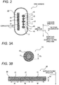
- Fig. 2 is a sectional view showing the wire harness WH shown in Fig. 1 .
- the wire harness WH includes a plurality of round electric wires 10, a flat electric wire 20, and a corrugated tube COT.
- the wire harness WH including the plurality of round electric wires 10 and one flat electric wire 20 will be described as an example, is not limited to this.
- the number of the round electric wires 10 may be one, and the number of flat electric wires 20 may be plural.
- Fig. 3A is an enlarged cross section of the round electric wire 10 of the wire harness WH shown in Fig. 2
- Fig. 3B shows an enlarged cross section of the flat electric wire 20 of the wire harness WH shown in Fig. 2 .
- the round electric wire 10 is an electric wire in which an insulating coating portion 12 is formed on a round conductor 11 having a round cross-sectional shape.
- the round conductor 11 is made of a predetermined metal such as copper, aluminum, or an alloy thereof having a certain degree of conductivity or more.
- a reference numeral T1 indicates a diameter of the round conductor 11.
- the flat electric wire 20 is an electric wire in which an insulating coating portion 22 is formed collectively with a plurality of flat conductors 21 having a flat cross-sectional shape (for example, flat quadrangle).
- the flat conductor 21 is made of the same metal as the round conductor 11, for example.
- a thicknesses T2 of the plurality of flat conductors 21 are unified to the same value.
- the plurality of flat conductors 21 have different widths W, for example.
- the corrugated tube COT shown in Fig. 2 is a protective tube having a rigidity higher than that of the coating portions 12, 22 in which the round electric wires 10 and the flat electric wire 20 are accommodated.
- the corrugated tube COT according to the present embodiment is formed so as to have an oblong cross section, and has a structure in which the flat electric wire 20 is accommodated along a long axis direction of the oblong and the plurality of round electric wires 10 and the flat electric wire 20 are stacked in a short axis direction.
- the corrugated tube COT Since the corrugated tube COT has the oblong cross section, the corrugated tube COT is easily bent in the short axis direction and is hardly bent in the long axis direction.
- directions of the corrugated tube COT and the flat electric wire 20 are adjusted so that a bending direction at the bent portion BP is the short axis direction.
- the bent portion BP the bending of the predetermined curvature is repeatedly applied in the surface folding direction (see Fig. 3B ) of the flat conductor 21.
- radii of curvature at a bent inner side and a bent outer side are different.
- a larger one of the curvature of the flat conductor 21 at the time of bending in one direction of the surface folding direction and the curvature of the round conductor 11 at the time of bending in the other one direction of the surface folding direction is taken as the predetermined curvature.
- the round conductor 11 is limited to one having a diameter T1 equal to or less than the reference value
- the flat conductor 21 has the thickness T2 equal to or less than the reference value and a width W in which ensure a cross-sectional area (the same allowable current) of the flat conductor more than area of a circular having the diameter equal to the reference value.
- the reference value is a predetermined value, and is a value determined to be equal to or less than a bending endurance limit value in the present embodiment.
- the bending endurance limit value refers to a minimum value of a thickness in a surface folding direction of a predetermined metal that satisfies a predetermined disconnection condition when a bending of the predetermined curvature described above is repeatedly applied a predetermined number of times in the surface folding direction.
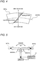
- Fig. 4 is a conceptual diagram showing the strain when the metal is bent. As shown in Fig. 4 , it is assumed that the bending with a thickness center position c of a metal MT as a reference is applied. In this case, a strain is generated due to the metal MT being compressed at a position apart from the thickness center position c toward the bent inner side. A compression strain increases as a distance from the thickness center position c toward the bent inner side increases. In addition, a strain is generated due to the metal MT being pulled at a position apart from the thickness center position c toward a bent outer side. A tensile strain increases as a distance from the thickness center position c toward the bent outer side increases. Accordingly, the larger the thickness in the bending direction is, the larger the strain.
- a predetermined disconnection condition is satisfied when the thickness is equal to or more than a certain thickness, and the predetermined disconnection condition is not satisfied when the thickness is less than the certain thickness.
- the bending endurance limit value is the minimum value of the thickness that satisfies the disconnection condition.
- the predetermined disconnection condition and the predetermined number of times are determined by an environment using the wire harness WH. That is, depending on a position where the wire harness WH is used, a condition that "the increase in a resistance value is less than 10% with respect to the bending of the predetermined curvature of 10000 times" is defined. Among them, the “10000 times” corresponds to the predetermined number of times, and “the increase in the resistance value is not less than 10%", that is, “the increase in the resistance value is 10% or more” corresponds to the disconnection condition.
- Fig. 5 is a conceptual diagram showing a method of obtaining the bending endurance limit value which satisfies the disconnection condition in the wire harness WH according to the present embodiment.
- the bending endurance limit value is obtained using a bending tester shown in Fig. 5 .
- the other end side of the electric wire was repeatedly bent at an angle range of -90° to 90° using a mandrel M with a bending radius of 12.5 mm at a room temperature (20°C), and the number of times of bending (the number of reciprocations) when the metal MT satisfied the disconnection condition was measured. Whether or not the disconnection condition was satisfied was determined based on whether or not a resistance value of a conductive portion CP was increased by a predetermined value (10%) or more using the conductive portion CP.
- a load of a weight B attached to one end of the electric wire was 400 g.
- a bending speed was 30 rpm.
- the angle range of the other end side of the electric wire, the diameter of the mandrel M, the load of the weight B, and the bending speed can be changed according to the use environment of the wire harness WH.
- the predetermined number of times that is, the number of times of bending obtained in the use environment
- the result was more than 10000 times that is the predetermined number of times.
- the thickness (diameter) was 1.1 mm or more
- the result was less than 10000 times that is the predetermined number of times.
- the bending endurance limit value can be obtained by the test.
- the bending endurance limit value may be a value calculated by a mathematical formula or the like.
- Fig. 6 is a graph for explaining a structure of the wire harness WH according to the present embodiment. First, the bending endurance limit value and the reference value will be described again.
- the wire harness WH according to the present embodiment is used for a slide door, it is assumed that a condition that "the increase in the resistance value is less than 10% with respect to the bending of the predetermined curvature of 10000 times" is defined.
- the minimum value of the thickness of the metal "in which the increase in the resistance value is 10% or more with respect to the bending of the predetermined curvature of 10000 times" becomes the bending endurance limit value.
- the bending endurance limit value is set to, for example, "1.8 (arbitrary unit)".
- the reference value is set to be equal to or less than the bending endurance limit value. Therefore, for example, the reference value is set to "1.5 (arbitrary unit)". Incidentally, the reference value may be the same as the bending endurance limit value.
- the round conductor 11 has the diameter T1 equal to or less than the reference value.
- the round conductors 11 of all round electric wires 10 have the diameter T1 equal to or less than the reference value.
- the round conductor 11 has the diameter T1 equal to or less than the reference value
- the allowable current value is desired to be increased
- the round electric wire 10 may not be able to cope with the problem. Therefore, for the flat conductor 21 of the flat electric wire 20, the width W (the width W is determined) is increased so that the thickness T2 is equal to or less than the reference value and has the same cross-sectional area as the round conductor 11 (broken circle portions shown in Fig. 6 ) having the diameter T1 exceeding the reference value. That is, the cross-sectional area of the flat conductor 21 is larger than a cross-sectional area of the round conductor 11. Accordingly, a situation in which the round conductor 11 having the diameter T1 equal to or less than the reference value cannot cope with a large allowable current value is prevented.
- the diameter T1 of the round conductor 11 and the thickness T2 of the flat conductor 21 are set to be equal to or less than the reference value equal to or less than the bending endurance limit value. Therefore, the strain applied to the round conductor 11 and the flat conductor 21 becomes smaller, and the disconnection condition is not satisfied for the round conductor 11 and the flat conductor 21 even after the bending of the predetermined number of times.
- the flat conductor 21 has the thickness T2 smaller than the diameter T1 of any of the round conductors 11. Accordingly, the bending resistance of the flat conductor 21 is further improved.
- the flat conductor 21 since the round conductor 11 has the diameter T1 equal to or less than the predetermined reference value, the flat conductor 21 has the thickness T2 equal to or less than the reference value, the bending resistance can be improved. Further, since the flat conductor 21 has the width W sufficient to ensure the same cross-sectional area as the round conductor 11 having the diameter T1 exceeding the reference value, the flat electric wire 20 functions as a substitute for the round electric wire 10 having the round conductor 11 exceeding the reference value, so that the number of the round electric wires 10 cannot be reduced more than necessary. Accordingly, it is less likely to occur that the number of round electric wires 10 decreases and it is difficult to cope with the increase or decrease in circuit. Therefore, in the wire harness WH in which the round electric wires 10 and the flat electric wire 20 are extended in parallel, it is possible to improve the bending resistance while facilitating coping with the increase or decrease in the circuit.
- the flat conductor 21 Since the thickness T2 of the flat conductor 21 is smaller than the diameter T1 of the round conductor 11, the flat conductor 21 can be made thinner and the bending resistance can be improved.
- the round conductor 11 is configured by one single wire, but is not limited thereto, and may be configured by a stranded wire.
- the diameter T1 corresponds to a diameter of each strand.
- the wire harness WH according to the present embodiment is not limited to a case where one bent portion BP is provided as shown in Fig. 1 , and may be provided with a plurality of bent portions BP.
- the flat conductor 21 is assumed to be the same metal as the round conductor 11, but may be a different metal.
Landscapes
- Insulated Conductors (AREA)
- Engineering & Computer Science (AREA)
- Mechanical Engineering (AREA)
- Details Of Indoor Wiring (AREA)
- Electric Cable Arrangement Between Relatively Moving Parts (AREA)
Abstract
Description
- The present invention relates to a wire harness.
- Conventionally, there has been known a flexible flat cable (hereinafter, referred to as an FFC) coated with an insulating resin so as to sandwich a plurality of flat conductors arranged in parallel from above and below. Compared to an electric wire (hereinafter referred to as a round electric wire) having a circular conductor cross section, the FFC has a large surface area and is excellent in heat dissipation, and thus may be used for an automobile. In addition, similar to the FFC, there is also a flexible printed circuit board (hereinafter referred to as FPC) in which a circuit pattern is formed on a flexible board.
- In a case where a flat electric wire such as the FFC or the FPC is used for the automobile, if there is an increase or decrease in an automobile circuit, it is necessary to review the entire circuit configuration of the flat electric wire, which makes it difficult to cope with increase or decrease in the circuit.
- Therefore, in order to cope with this problem, a wire harness in which a round electric wire is extended in parallel with respect to a flat electric wire has been proposed (see
Patent Literatures 1 to 3). In the wire harness, even when there is an increase or decrease in an automobile circuit, by changing the round electric wire, it is not necessary to review the entire circuit configuration of the flat electric wire, and it is possible to facilitate coping with the increase and decrease in the circuit. - [Patent Literature 1]
JP-A-2002-367439 - [Patent Literature 2]
JP-A-2013-37801 - [Patent Literature 3]
JP-A-2013-37805 - However, for the round electric wire, a diameter of a conductor (hereinafter, referred to as a round conductor) having a circular cross section tends to be larger than a thickness of a flat conductor of the flat electric wire. The reason for this is as follows. A cross-sectional area of the conductor is determined by a current value (allowable current value) flowing through the conductor. For the flat electric wire, since the flat conductor has a constant thickness, the flat conductor tends to increase in a width direction (direction orthogonal to a thickness direction in a cross-sectional view) when the allowable current value increases. However, for the round electric wire, the diameter of the round conductor increases when the allowable current value increases. Accordingly, for the round electric wire, the diameter of the round conductor tends to be larger than the thickness of the flat conductor of the flat electric wire.
- Here, for the round conductor having a large diameter, a strain applied at the time of bending tends to be larger. Therefore, in a case where a wire harness in which the round electric wire and the flat electric wire are mixed is used for a bent portion to which bending is repeatedly applied, only the round electric wire is disconnected first (including a case where a resistance value is increased by a predetermined value or more), and it never be said that a bending resistance of the wire harness is high. Therefore, when the number of round electric wires is reduced, the bending resistance of the wire harness can be improved, but when there is an increase or decrease in the automobile circuit, a circuit configuration of the flat electric wire is likely to be reviewed, which makes it difficult to cope with the increase or decrease in the circuit.
- One or more embodiments provide a bending resistance while facilitating coping with an increase and decrease in a circuit, in a wire harness in which a round electric wire and a flat electric wire are extended in parallel.
- A wire harness including a round electric wire and a flat electric wire. The round electric wire includes a round conductor made of a predetermined metal and having a round cross-sectional shape and a first coating portion. The flat electric wire includes a flat conductor having a flat cross-sectional shape and a second coating portion. The round electric wire and the flat electric wire are arranged in parallel. The round conductor has a diameter equal to or less than a predetermined reference value. The flat conductor has a thickness equal to or less than the reference value and a width in which ensure cross-sectional area of the flat conductor more than area of circle having a diameter equal to the reference value.
The present invention is a wire harness in which a round electric wire and a flat electric wire are arranged in parallel. A round conductor of the wire harness has a diameter equal to or less than a predetermined reference value, and a flat conductor of the wire harness has a thickness equal to or less than the reference value, and has a width sufficient to ensure the same cross-sectional area as the round conductor having a diameter exceeding the reference value. - According to the present invention, since the round conductor has the diameter equal to or less than the predetermined reference value, the flat conductor has the thickness equal to or less than the reference value, so that a bending resistance can be improved. Further, since the flat conductor has the width sufficient to ensure the same cross-sectional area as the round conductor having the diameter exceeding the reference value, the flat electric wire functions as a substitute for the round electric wire having a round conductor exceeding the reference value, and the number of round electric wires cannot be reduced more than necessary. Accordingly, it is less likely to occur that the number of round electric wires decreases and it is difficult to cope with the increase or decrease in circuit. Therefore, in the wire harness in which the round electric wire and the flat electric wire are extended in parallel, it is possible to improve the bending resistance while facilitating coping with the increase or decrease in the circuit.
- According to one or more embodiments, in a wire harness in which a round electric wire and a flat electric wire are extended in parallel, it is possible to increase a bending resistance while facilitating coping with an increase or decrease in the circuit.
-
-
Fig. 1 is a perspective view showing a wiring structure of a wire harness according to an embodiment of the present invention. -
Fig. 2 is a sectional view showing the wire harness shown inFig. 1 . -
Fig. 3A is an enlarged cross section of a round electric wire of the wire harness shown inFig. 2. Fig. 3B shows an enlarged cross section of a flat electric wire of the wire harness shown inFig. 2 . -
Fig. 4 is a conceptual diagram showing a strain when a metal is bent. -
Fig. 5 is a conceptual diagram showing a method of obtaining a bending endurance limit value which satisfies a disconnection condition in the wire harness according to the present embodiment. -
Fig. 6 is a graph for explaining a structure of the wire harness according to the present embodiment. - Hereinafter, the present invention will be described in accordance with a preferred embodiment. The present invention is not limited to the following embodiments, and can be modified as appropriate without departing from the scope of the present invention. In addition, in the embodiment described below, some configurations are not shown or described, but it goes without saying that a known or well-known technique is applied as appropriate to details of an omitted technique within a range in which no contradiction occurs to contents to be described below.
-
Fig. 1 is a perspective view showing a wiring structure of a wire harness according to an embodiment of the present invention. Awiring structure 1 of a wire harness WH shown inFig. 1 has a structure in which the wire harness WH is wired at a bent portion BP. The bent portion BP is a portion at which a bending of a predetermined curvature is repeatedly applied in a surface folding direction of a flat conductor of a flat electric wire described later. The predetermined curvature differs depending on the bent portion BP at which the wire harness WH is wired, and has different values at the bent portion BP of a slide door and the bent portion BP of a door that is normal opened/closed, for example. In addition, the predetermined curvature may be different depending on each vehicle, each grade, or the like. -
Fig. 2 is a sectional view showing the wire harness WH shown inFig. 1 . As shown inFig. 2 , the wire harness WH includes a plurality of roundelectric wires 10, a flatelectric wire 20, and a corrugated tube COT. Although the wire harness WH including the plurality of roundelectric wires 10 and one flatelectric wire 20 will be described as an example, is not limited to this. The number of the roundelectric wires 10 may be one, and the number of flatelectric wires 20 may be plural. - In
Fig. 3, Fig. 3A is an enlarged cross section of the roundelectric wire 10 of the wire harness WH shown inFig. 2, and Fig. 3B shows an enlarged cross section of the flatelectric wire 20 of the wire harness WH shown inFig. 2 . - As shown in
Fig. 3A , the roundelectric wire 10 is an electric wire in which aninsulating coating portion 12 is formed on around conductor 11 having a round cross-sectional shape. Theround conductor 11 is made of a predetermined metal such as copper, aluminum, or an alloy thereof having a certain degree of conductivity or more. A reference numeral T1 indicates a diameter of theround conductor 11. - As shown in
Fig. 3B , the flatelectric wire 20 is an electric wire in which an insulatingcoating portion 22 is formed collectively with a plurality offlat conductors 21 having a flat cross-sectional shape (for example, flat quadrangle). Theflat conductor 21 is made of the same metal as theround conductor 11, for example. In the flatelectric wire 20, a thicknesses T2 of the plurality offlat conductors 21 are unified to the same value. On the other hand, in the flatelectric wire 20 according to the present embodiment, the plurality offlat conductors 21 have different widths W, for example. - The corrugated tube COT shown in
Fig. 2 is a protective tube having a rigidity higher than that of thecoating portions electric wires 10 and the flatelectric wire 20 are accommodated. The corrugated tube COT according to the present embodiment is formed so as to have an oblong cross section, and has a structure in which the flatelectric wire 20 is accommodated along a long axis direction of the oblong and the plurality of roundelectric wires 10 and the flatelectric wire 20 are stacked in a short axis direction. - Since the corrugated tube COT has the oblong cross section, the corrugated tube COT is easily bent in the short axis direction and is hardly bent in the long axis direction. In the wire harness WH of the present embodiment, directions of the corrugated tube COT and the flat
electric wire 20 are adjusted so that a bending direction at the bent portion BP is the short axis direction. As a result, at the bent portion BP, the bending of the predetermined curvature is repeatedly applied in the surface folding direction (seeFig. 3B ) of theflat conductor 21. - In a case where the wire harness WH is bent in the short axis direction (surface folding direction) of the corrugated tube COT, radii of curvature at a bent inner side and a bent outer side are different. In the present embodiment, a larger one of the curvature of the
flat conductor 21 at the time of bending in one direction of the surface folding direction and the curvature of theround conductor 11 at the time of bending in the other one direction of the surface folding direction is taken as the predetermined curvature. - In the present embodiment, the
round conductor 11 is limited to one having a diameter T1 equal to or less than the reference value, and theflat conductor 21 has the thickness T2 equal to or less than the reference value and a width W in which ensure a cross-sectional area (the same allowable current) of the flat conductor more than area of a circular having the diameter equal to the reference value. - The reference value is a predetermined value, and is a value determined to be equal to or less than a bending endurance limit value in the present embodiment. The bending endurance limit value refers to a minimum value of a thickness in a surface folding direction of a predetermined metal that satisfies a predetermined disconnection condition when a bending of the predetermined curvature described above is repeatedly applied a predetermined number of times in the surface folding direction. Hereinafter, it will be described in detail.
- First, when the bending (bending in a plastic area) of the predetermined curvature is applied to the metal, a strain is generated. Then, the strain is accumulated by repeating the bending of predetermined curvature, and eventually the metal is broken. Here, at the time of the bending, when the thickness in the bending direction increases, the strain also tends to increase.
-
Fig. 4 is a conceptual diagram showing the strain when the metal is bent. As shown inFig. 4 , it is assumed that the bending with a thickness center position c of a metal MT as a reference is applied. In this case, a strain is generated due to the metal MT being compressed at a position apart from the thickness center position c toward the bent inner side. A compression strain increases as a distance from the thickness center position c toward the bent inner side increases. In addition, a strain is generated due to the metal MT being pulled at a position apart from the thickness center position c toward a bent outer side. A tensile strain increases as a distance from the thickness center position c toward the bent outer side increases. Accordingly, the larger the thickness in the bending direction is, the larger the strain. - As described above, in a case where the bending of the predetermined curvature described above is repeatedly applied the predetermined number of times in the surface folding direction, a predetermined disconnection condition is satisfied when the thickness is equal to or more than a certain thickness, and the predetermined disconnection condition is not satisfied when the thickness is less than the certain thickness. The bending endurance limit value is the minimum value of the thickness that satisfies the disconnection condition.
- The predetermined disconnection condition and the predetermined number of times are determined by an environment using the wire harness WH. That is, depending on a position where the wire harness WH is used, a condition that "the increase in a resistance value is less than 10% with respect to the bending of the predetermined curvature of 10000 times" is defined. Among them, the "10000 times" corresponds to the predetermined number of times, and "the increase in the resistance value is not less than 10%", that is, "the increase in the resistance value is 10% or more" corresponds to the disconnection condition. Incidentally, depending on the environment in which the wire harness WH is used, there may be a case where a condition that "the increase in the resistance value is less than 5% with respect to the bending of the predetermined curvature of 1000000 times" is defined. In this case, the "1000000 times" corresponds to the predetermined number of times, and "the increase in the resistance value is 5% or more" corresponds to the disconnection condition.
-
Fig. 5 is a conceptual diagram showing a method of obtaining the bending endurance limit value which satisfies the disconnection condition in the wire harness WH according to the present embodiment. The bending endurance limit value is obtained using a bending tester shown inFig. 5 . - Specifically, from a state where one end of the electric wire coated with the metal MT having a predetermined thickness (diameter) was fixed and the electric wire was straightened, for example, the other end side of the electric wire was repeatedly bent at an angle range of -90° to 90° using a mandrel M with a bending radius of 12.5 mm at a room temperature (20°C), and the number of times of bending (the number of reciprocations) when the metal MT satisfied the disconnection condition was measured. Whether or not the disconnection condition was satisfied was determined based on whether or not a resistance value of a conductive portion CP was increased by a predetermined value (10%) or more using the conductive portion CP. A load of a weight B attached to one end of the electric wire was 400 g. In addition, a bending speed was 30 rpm. The angle range of the other end side of the electric wire, the diameter of the mandrel M, the load of the weight B, and the bending speed can be changed according to the use environment of the wire harness WH.
- In the above example, assuming that the predetermined number of times (that is, the number of times of bending obtained in the use environment) related to the disconnection condition was 10000 times, in a case where the thickness (diameter) was 1 mm or less, the result was more than 10000 times that is the predetermined number of times. On the other hand, in a case where the thickness (diameter) was 1.1 mm or more, the result was less than 10000 times that is the predetermined number of times. Through the test described above, it was found that the bending endurance limit value in the above case was 1 mm.
- As described above, the bending endurance limit value can be obtained by the test. Incidentally, if possible, the bending endurance limit value may be a value calculated by a mathematical formula or the like.
-
Fig. 6 is a graph for explaining a structure of the wire harness WH according to the present embodiment. First, the bending endurance limit value and the reference value will be described again. - For example, in a case where the wire harness WH according to the present embodiment is used for a slide door, it is assumed that a condition that "the increase in the resistance value is less than 10% with respect to the bending of the predetermined curvature of 10000 times" is defined. In this case, the minimum value of the thickness of the metal "in which the increase in the resistance value is 10% or more with respect to the bending of the predetermined curvature of 10000 times" becomes the bending endurance limit value. The bending endurance limit value is set to, for example, "1.8 (arbitrary unit)".
- The reference value is set to be equal to or less than the bending endurance limit value. Therefore, for example, the reference value is set to "1.5 (arbitrary unit)". Incidentally, the reference value may be the same as the bending endurance limit value.
- Next, the
round conductor 11 and theflat conductor 21 according to the present embodiment will be described. In the present embodiment, theround conductor 11 has the diameter T1 equal to or less than the reference value. In the case where the plurality of roundelectric wires 10 are provided, theround conductors 11 of all roundelectric wires 10 have the diameter T1 equal to or less than the reference value. - Here, when the
round conductor 11 has the diameter T1 equal to or less than the reference value, in a case where the allowable current value is desired to be increased, the roundelectric wire 10 may not be able to cope with the problem. Therefore, for theflat conductor 21 of the flatelectric wire 20, the width W (the width W is determined) is increased so that the thickness T2 is equal to or less than the reference value and has the same cross-sectional area as the round conductor 11 (broken circle portions shown inFig. 6 ) having the diameter T1 exceeding the reference value. That is, the cross-sectional area of theflat conductor 21 is larger than a cross-sectional area of theround conductor 11. Accordingly, a situation in which theround conductor 11 having the diameter T1 equal to or less than the reference value cannot cope with a large allowable current value is prevented. - In the wire harness WH, even if the bending of the predetermined number of times is applied in the surface folding direction, the diameter T1 of the
round conductor 11 and the thickness T2 of theflat conductor 21 are set to be equal to or less than the reference value equal to or less than the bending endurance limit value. Therefore, the strain applied to theround conductor 11 and theflat conductor 21 becomes smaller, and the disconnection condition is not satisfied for theround conductor 11 and theflat conductor 21 even after the bending of the predetermined number of times. - In particular, as shown in
Fig. 6 , in the present embodiment, theflat conductor 21 has the thickness T2 smaller than the diameter T1 of any of theround conductors 11. Accordingly, the bending resistance of theflat conductor 21 is further improved. - In this way, according to the wire harness WH according to the present embodiment, since the
round conductor 11 has the diameter T1 equal to or less than the predetermined reference value, theflat conductor 21 has the thickness T2 equal to or less than the reference value, the bending resistance can be improved. Further, since theflat conductor 21 has the width W sufficient to ensure the same cross-sectional area as theround conductor 11 having the diameter T1 exceeding the reference value, the flatelectric wire 20 functions as a substitute for the roundelectric wire 10 having theround conductor 11 exceeding the reference value, so that the number of the roundelectric wires 10 cannot be reduced more than necessary. Accordingly, it is less likely to occur that the number of roundelectric wires 10 decreases and it is difficult to cope with the increase or decrease in circuit. Therefore, in the wire harness WH in which the roundelectric wires 10 and the flatelectric wire 20 are extended in parallel, it is possible to improve the bending resistance while facilitating coping with the increase or decrease in the circuit. - Since the thickness T2 of the
flat conductor 21 is smaller than the diameter T1 of theround conductor 11, theflat conductor 21 can be made thinner and the bending resistance can be improved. - Although the present invention has been described above based on the embodiment, the present invention is not limited to the above embodiment, and changes may be made without departing from the spirit of the present invention.
- For example, in the round
electric wire 10 according to the present embodiment, theround conductor 11 is configured by one single wire, but is not limited thereto, and may be configured by a stranded wire. In this case, the diameter T1 corresponds to a diameter of each strand. - The wire harness WH according to the present embodiment is not limited to a case where one bent portion BP is provided as shown in
Fig. 1 , and may be provided with a plurality of bent portions BP. - The
flat conductor 21 is assumed to be the same metal as theround conductor 11, but may be a different metal. -
- 1:
- wiring structure of wire harness
- 10:
- round electric wire
- 11:
- round conductor
- 12:
- coating portion
- 20:
- flat electric wire
- 21:
- flat conductor
- 22:
- coating portion
- BP:
- bent portion
- T1:
- diameter
- T2:
- thickness
- W:
- width
- WH:
- wire harness
Claims (3)
- A wire harness comprising:a round electric wire; anda flat electric wire,wherein the round electric wire includes a round conductor made of a predetermined metal and having a round cross-sectional shape and a first coating portion,wherein the flat electric wire includes a flat conductor having a flat cross-sectional shape and a second coating portion,wherein the round electric wire and the flat electric wire are arranged in parallel,wherein the round conductor has a diameter equal to or less than a predetermined reference value, andwherein the flat conductor has a thickness equal to or less than the reference value and a width in which ensure cross-sectional area of the flat conductor more than area of a circle having a diameter equal to the reference value.
- The wire harness according to claim 1,
wherein the thickness of the flat conductor is smaller than the diameter of the round conductor. - The wire harness according to claim 1,
wherein the reference value is a value determined to be equal to or less than a bending endurance limit value, and
wherein the bending endurance limit value is a minimum value of a thickness in a surface folding direction of a predetermined metal that satisfies a predetermined disconnection condition when a bending of a predetermined curvature is repeatedly applied a predetermined number of times in the surface folding direction.
Applications Claiming Priority (1)
| Application Number | Priority Date | Filing Date | Title |
|---|---|---|---|
| JP2018178365A JP6846393B2 (en) | 2018-09-25 | 2018-09-25 | Wire Harness |
Publications (2)
| Publication Number | Publication Date |
|---|---|
| EP3653446A1 true EP3653446A1 (en) | 2020-05-20 |
| EP3653446B1 EP3653446B1 (en) | 2020-11-18 |
Family
ID=67777114
Family Applications (1)
| Application Number | Title | Priority Date | Filing Date |
|---|---|---|---|
| EP19193953.7A Active EP3653446B1 (en) | 2018-09-25 | 2019-08-28 | Wire harness |
Country Status (4)
| Country | Link |
|---|---|
| US (1) | US10847280B2 (en) |
| EP (1) | EP3653446B1 (en) |
| JP (1) | JP6846393B2 (en) |
| CN (1) | CN110942845A (en) |
Families Citing this family (5)
| Publication number | Priority date | Publication date | Assignee | Title |
|---|---|---|---|---|
| JP2020145027A (en) * | 2019-03-05 | 2020-09-10 | 株式会社オートネットワーク技術研究所 | Wire harness and wire harness routing device |
| DE102019130078A1 (en) * | 2019-11-07 | 2021-05-12 | Auto-Kabel Management Gmbh | Motor vehicle power line and a method for bending a motor vehicle power line |
| WO2022131231A1 (en) | 2020-12-16 | 2022-06-23 | ファナック株式会社 | Power harness and robot |
| CN114068075A (en) * | 2021-12-24 | 2022-02-18 | 广东麦米电工技术有限公司 | A kind of multi-strand flat enameled wire and its manufacturing method |
| CN114725864B (en) * | 2022-03-16 | 2024-06-18 | 延锋国际座椅系统有限公司 | Automobile wire harness box device with flat cable |
Citations (7)
| Publication number | Priority date | Publication date | Assignee | Title |
|---|---|---|---|---|
| JP2002367439A (en) | 2001-06-12 | 2002-12-20 | Sumitomo Wiring Syst Ltd | Flat harness |
| EP1453068A1 (en) * | 2003-02-26 | 2004-09-01 | I & T Flachleiter Produktions-Ges.m.b.h. | Flat conductor cable |
| US6969807B1 (en) * | 2004-07-20 | 2005-11-29 | Advanced Flexible Circuits Co., Ltd. | Planar type flexible cable with shielding structure |
| EP2533252A1 (en) * | 2010-02-05 | 2012-12-12 | Yazaki Corporation | Wire harness |
| JP2013037805A (en) | 2011-08-04 | 2013-02-21 | Auto Network Gijutsu Kenkyusho:Kk | Insulation electric wire and wire harness |
| JP2013037801A (en) | 2011-08-04 | 2013-02-21 | Auto Network Gijutsu Kenkyusho:Kk | Insulation electric wire and wire harness |
| WO2018029291A1 (en) * | 2016-08-11 | 2018-02-15 | Lisa Dräxlmaier GmbH | Flat electric conductor arrangement and method for the production thereof |
Family Cites Families (9)
| Publication number | Priority date | Publication date | Assignee | Title |
|---|---|---|---|---|
| US3459879A (en) * | 1967-05-29 | 1969-08-05 | Hughes Aircraft Co | Flexible multiflat conductor characteristic impedance cable |
| JPS56158502A (en) * | 1980-05-12 | 1981-12-07 | Junkosha Co Ltd | Strip line |
| JPH01253122A (en) * | 1988-03-31 | 1989-10-09 | Showa Electric Wire & Cable Co Ltd | Manufacture of flat cable |
| JPH05217429A (en) * | 1992-01-31 | 1993-08-27 | Yazaki Corp | Tape electric wire and method of manufacturing the same |
| JP2002222615A (en) * | 2001-01-24 | 2002-08-09 | Auto Network Gijutsu Kenkyusho:Kk | Flat wire harness |
| DE10331710B4 (en) * | 2003-07-11 | 2008-05-08 | W. L. Gore & Associates Gmbh | cable |
| US20080053682A1 (en) * | 2003-07-16 | 2008-03-06 | Jay Victor | Cable Structure |
| CN2650300Y (en) * | 2003-10-17 | 2004-10-20 | 永琨有限公司 | A new structure of audio and video signal line |
| US8404976B2 (en) * | 2009-01-30 | 2013-03-26 | Fort Wayne Metals Research Products Corporation | Fused wires |
-
2018
- 2018-09-25 JP JP2018178365A patent/JP6846393B2/en active Active
-
2019
- 2019-08-28 US US16/554,576 patent/US10847280B2/en active Active
- 2019-08-28 EP EP19193953.7A patent/EP3653446B1/en active Active
- 2019-08-29 CN CN201910809454.6A patent/CN110942845A/en active Pending
Patent Citations (7)
| Publication number | Priority date | Publication date | Assignee | Title |
|---|---|---|---|---|
| JP2002367439A (en) | 2001-06-12 | 2002-12-20 | Sumitomo Wiring Syst Ltd | Flat harness |
| EP1453068A1 (en) * | 2003-02-26 | 2004-09-01 | I & T Flachleiter Produktions-Ges.m.b.h. | Flat conductor cable |
| US6969807B1 (en) * | 2004-07-20 | 2005-11-29 | Advanced Flexible Circuits Co., Ltd. | Planar type flexible cable with shielding structure |
| EP2533252A1 (en) * | 2010-02-05 | 2012-12-12 | Yazaki Corporation | Wire harness |
| JP2013037805A (en) | 2011-08-04 | 2013-02-21 | Auto Network Gijutsu Kenkyusho:Kk | Insulation electric wire and wire harness |
| JP2013037801A (en) | 2011-08-04 | 2013-02-21 | Auto Network Gijutsu Kenkyusho:Kk | Insulation electric wire and wire harness |
| WO2018029291A1 (en) * | 2016-08-11 | 2018-02-15 | Lisa Dräxlmaier GmbH | Flat electric conductor arrangement and method for the production thereof |
Also Published As
| Publication number | Publication date |
|---|---|
| US10847280B2 (en) | 2020-11-24 |
| JP2020053124A (en) | 2020-04-02 |
| US20200098489A1 (en) | 2020-03-26 |
| JP6846393B2 (en) | 2021-03-24 |
| CN110942845A (en) | 2020-03-31 |
| EP3653446B1 (en) | 2020-11-18 |
Similar Documents
| Publication | Publication Date | Title |
|---|---|---|
| EP3653446B1 (en) | Wire harness | |
| KR101001804B1 (en) | Coaxial cable connection structure, coaxial cable harness used for it, and portable terminal equipment | |
| US9346420B2 (en) | Wire harness | |
| JP6114331B2 (en) | Bending resistant wire and wire harness | |
| JP4168079B2 (en) | Electronic device and wiring method of harness in electronic device | |
| US20050029006A1 (en) | Signal transmission cable terminal device and data transmission method using signal transmission cable | |
| US20100276179A1 (en) | Multilayer cable jacket | |
| JP4044805B2 (en) | Flat shielded cable | |
| GB2196468A (en) | A flexible tramsmission cable | |
| JP7265324B2 (en) | insulated wire, cable | |
| JP4044766B2 (en) | Flat shielded cable | |
| CN108417293A (en) | Aluminum Composite Stranded Wire Conductors, Aluminum Composite Stranded Wires and Wire Harnesses | |
| JP6164844B2 (en) | Insulated wire, coaxial cable and multi-core cable | |
| US11694823B2 (en) | Ethernet cable | |
| JP5128141B2 (en) | Electronic equipment and wiring harness for electronic equipment | |
| EP3813081B1 (en) | Communication cable and wire harness | |
| JP6572661B2 (en) | Jumper wire | |
| KR20200101262A (en) | Ethernet cable | |
| JP6852023B2 (en) | Composite cable | |
| US20240412895A1 (en) | Shielded electrical conductor with folded shielding layer | |
| JP4821983B2 (en) | Electric cable | |
| JP2008257969A (en) | Electronic equipment and wiring harness for electronic equipment | |
| US8917526B2 (en) | Flat cable and cable harness using the same | |
| US20030141099A1 (en) | Flat shield cable | |
| JP2010114003A (en) | Cable assembly |
Legal Events
| Date | Code | Title | Description |
|---|---|---|---|
| PUAI | Public reference made under article 153(3) epc to a published international application that has entered the european phase |
Free format text: ORIGINAL CODE: 0009012 |
|
| STAA | Information on the status of an ep patent application or granted ep patent |
Free format text: STATUS: REQUEST FOR EXAMINATION WAS MADE |
|
| 17P | Request for examination filed |
Effective date: 20190828 |
|
| AK | Designated contracting states |
Kind code of ref document: A1 Designated state(s): AL AT BE BG CH CY CZ DE DK EE ES FI FR GB GR HR HU IE IS IT LI LT LU LV MC MK MT NL NO PL PT RO RS SE SI SK SM TR |
|
| AX | Request for extension of the european patent |
Extension state: BA ME |
|
| RIC1 | Information provided on ipc code assigned before grant |
Ipc: B60R 16/02 20060101AFI20200729BHEP |
|
| GRAP | Despatch of communication of intention to grant a patent |
Free format text: ORIGINAL CODE: EPIDOSNIGR1 |
|
| STAA | Information on the status of an ep patent application or granted ep patent |
Free format text: STATUS: GRANT OF PATENT IS INTENDED |
|
| INTG | Intention to grant announced |
Effective date: 20200904 |
|
| GRAS | Grant fee paid |
Free format text: ORIGINAL CODE: EPIDOSNIGR3 |
|
| GRAA | (expected) grant |
Free format text: ORIGINAL CODE: 0009210 |
|
| STAA | Information on the status of an ep patent application or granted ep patent |
Free format text: STATUS: THE PATENT HAS BEEN GRANTED |
|
| AK | Designated contracting states |
Kind code of ref document: B1 Designated state(s): AL AT BE BG CH CY CZ DE DK EE ES FI FR GB GR HR HU IE IS IT LI LT LU LV MC MK MT NL NO PL PT RO RS SE SI SK SM TR |
|
| REG | Reference to a national code |
Ref country code: GB Ref legal event code: FG4D |
|
| REG | Reference to a national code |
Ref country code: CH Ref legal event code: EP |
|
| REG | Reference to a national code |
Ref country code: IE Ref legal event code: FG4D |
|
| REG | Reference to a national code |
Ref country code: DE Ref legal event code: R096 Ref document number: 602019001376 Country of ref document: DE |
|
| REG | Reference to a national code |
Ref country code: AT Ref legal event code: REF Ref document number: 1335423 Country of ref document: AT Kind code of ref document: T Effective date: 20201215 |
|
| REG | Reference to a national code |
Ref country code: AT Ref legal event code: MK05 Ref document number: 1335423 Country of ref document: AT Kind code of ref document: T Effective date: 20201118 |
|
| REG | Reference to a national code |
Ref country code: NL Ref legal event code: MP Effective date: 20201118 |
|
| PG25 | Lapsed in a contracting state [announced via postgrant information from national office to epo] |
Ref country code: NO Free format text: LAPSE BECAUSE OF FAILURE TO SUBMIT A TRANSLATION OF THE DESCRIPTION OR TO PAY THE FEE WITHIN THE PRESCRIBED TIME-LIMIT Effective date: 20210218 Ref country code: GR Free format text: LAPSE BECAUSE OF FAILURE TO SUBMIT A TRANSLATION OF THE DESCRIPTION OR TO PAY THE FEE WITHIN THE PRESCRIBED TIME-LIMIT Effective date: 20210219 Ref country code: PT Free format text: LAPSE BECAUSE OF FAILURE TO SUBMIT A TRANSLATION OF THE DESCRIPTION OR TO PAY THE FEE WITHIN THE PRESCRIBED TIME-LIMIT Effective date: 20210318 Ref country code: RS Free format text: LAPSE BECAUSE OF FAILURE TO SUBMIT A TRANSLATION OF THE DESCRIPTION OR TO PAY THE FEE WITHIN THE PRESCRIBED TIME-LIMIT Effective date: 20201118 Ref country code: FI Free format text: LAPSE BECAUSE OF FAILURE TO SUBMIT A TRANSLATION OF THE DESCRIPTION OR TO PAY THE FEE WITHIN THE PRESCRIBED TIME-LIMIT Effective date: 20201118 |
|
| PG25 | Lapsed in a contracting state [announced via postgrant information from national office to epo] |
Ref country code: LV Free format text: LAPSE BECAUSE OF FAILURE TO SUBMIT A TRANSLATION OF THE DESCRIPTION OR TO PAY THE FEE WITHIN THE PRESCRIBED TIME-LIMIT Effective date: 20201118 Ref country code: IS Free format text: LAPSE BECAUSE OF FAILURE TO SUBMIT A TRANSLATION OF THE DESCRIPTION OR TO PAY THE FEE WITHIN THE PRESCRIBED TIME-LIMIT Effective date: 20210318 Ref country code: PL Free format text: LAPSE BECAUSE OF FAILURE TO SUBMIT A TRANSLATION OF THE DESCRIPTION OR TO PAY THE FEE WITHIN THE PRESCRIBED TIME-LIMIT Effective date: 20201118 Ref country code: SE Free format text: LAPSE BECAUSE OF FAILURE TO SUBMIT A TRANSLATION OF THE DESCRIPTION OR TO PAY THE FEE WITHIN THE PRESCRIBED TIME-LIMIT Effective date: 20201118 Ref country code: BG Free format text: LAPSE BECAUSE OF FAILURE TO SUBMIT A TRANSLATION OF THE DESCRIPTION OR TO PAY THE FEE WITHIN THE PRESCRIBED TIME-LIMIT Effective date: 20210218 Ref country code: AT Free format text: LAPSE BECAUSE OF FAILURE TO SUBMIT A TRANSLATION OF THE DESCRIPTION OR TO PAY THE FEE WITHIN THE PRESCRIBED TIME-LIMIT Effective date: 20201118 |
|
| REG | Reference to a national code |
Ref country code: LT Ref legal event code: MG9D |
|
| PG25 | Lapsed in a contracting state [announced via postgrant information from national office to epo] |
Ref country code: HR Free format text: LAPSE BECAUSE OF FAILURE TO SUBMIT A TRANSLATION OF THE DESCRIPTION OR TO PAY THE FEE WITHIN THE PRESCRIBED TIME-LIMIT Effective date: 20201118 |
|
| PG25 | Lapsed in a contracting state [announced via postgrant information from national office to epo] |
Ref country code: LT Free format text: LAPSE BECAUSE OF FAILURE TO SUBMIT A TRANSLATION OF THE DESCRIPTION OR TO PAY THE FEE WITHIN THE PRESCRIBED TIME-LIMIT Effective date: 20201118 Ref country code: RO Free format text: LAPSE BECAUSE OF FAILURE TO SUBMIT A TRANSLATION OF THE DESCRIPTION OR TO PAY THE FEE WITHIN THE PRESCRIBED TIME-LIMIT Effective date: 20201118 Ref country code: CZ Free format text: LAPSE BECAUSE OF FAILURE TO SUBMIT A TRANSLATION OF THE DESCRIPTION OR TO PAY THE FEE WITHIN THE PRESCRIBED TIME-LIMIT Effective date: 20201118 Ref country code: EE Free format text: LAPSE BECAUSE OF FAILURE TO SUBMIT A TRANSLATION OF THE DESCRIPTION OR TO PAY THE FEE WITHIN THE PRESCRIBED TIME-LIMIT Effective date: 20201118 Ref country code: SM Free format text: LAPSE BECAUSE OF FAILURE TO SUBMIT A TRANSLATION OF THE DESCRIPTION OR TO PAY THE FEE WITHIN THE PRESCRIBED TIME-LIMIT Effective date: 20201118 Ref country code: SK Free format text: LAPSE BECAUSE OF FAILURE TO SUBMIT A TRANSLATION OF THE DESCRIPTION OR TO PAY THE FEE WITHIN THE PRESCRIBED TIME-LIMIT Effective date: 20201118 |
|
| REG | Reference to a national code |
Ref country code: DE Ref legal event code: R097 Ref document number: 602019001376 Country of ref document: DE |
|
| PG25 | Lapsed in a contracting state [announced via postgrant information from national office to epo] |
Ref country code: DK Free format text: LAPSE BECAUSE OF FAILURE TO SUBMIT A TRANSLATION OF THE DESCRIPTION OR TO PAY THE FEE WITHIN THE PRESCRIBED TIME-LIMIT Effective date: 20201118 |
|
| PLBE | No opposition filed within time limit |
Free format text: ORIGINAL CODE: 0009261 |
|
| STAA | Information on the status of an ep patent application or granted ep patent |
Free format text: STATUS: NO OPPOSITION FILED WITHIN TIME LIMIT |
|
| 26N | No opposition filed |
Effective date: 20210819 |
|
| PG25 | Lapsed in a contracting state [announced via postgrant information from national office to epo] |
Ref country code: IT Free format text: LAPSE BECAUSE OF FAILURE TO SUBMIT A TRANSLATION OF THE DESCRIPTION OR TO PAY THE FEE WITHIN THE PRESCRIBED TIME-LIMIT Effective date: 20201118 Ref country code: NL Free format text: LAPSE BECAUSE OF FAILURE TO SUBMIT A TRANSLATION OF THE DESCRIPTION OR TO PAY THE FEE WITHIN THE PRESCRIBED TIME-LIMIT Effective date: 20201118 Ref country code: AL Free format text: LAPSE BECAUSE OF FAILURE TO SUBMIT A TRANSLATION OF THE DESCRIPTION OR TO PAY THE FEE WITHIN THE PRESCRIBED TIME-LIMIT Effective date: 20201118 |
|
| PG25 | Lapsed in a contracting state [announced via postgrant information from national office to epo] |
Ref country code: SI Free format text: LAPSE BECAUSE OF FAILURE TO SUBMIT A TRANSLATION OF THE DESCRIPTION OR TO PAY THE FEE WITHIN THE PRESCRIBED TIME-LIMIT Effective date: 20201118 |
|
| PG25 | Lapsed in a contracting state [announced via postgrant information from national office to epo] |
Ref country code: ES Free format text: LAPSE BECAUSE OF FAILURE TO SUBMIT A TRANSLATION OF THE DESCRIPTION OR TO PAY THE FEE WITHIN THE PRESCRIBED TIME-LIMIT Effective date: 20201118 |
|
| PG25 | Lapsed in a contracting state [announced via postgrant information from national office to epo] |
Ref country code: MC Free format text: LAPSE BECAUSE OF FAILURE TO SUBMIT A TRANSLATION OF THE DESCRIPTION OR TO PAY THE FEE WITHIN THE PRESCRIBED TIME-LIMIT Effective date: 20201118 |
|
| REG | Reference to a national code |
Ref country code: BE Ref legal event code: MM Effective date: 20210831 |
|
| PG25 | Lapsed in a contracting state [announced via postgrant information from national office to epo] |
Ref country code: IS Free format text: LAPSE BECAUSE OF FAILURE TO SUBMIT A TRANSLATION OF THE DESCRIPTION OR TO PAY THE FEE WITHIN THE PRESCRIBED TIME-LIMIT Effective date: 20210318 Ref country code: LU Free format text: LAPSE BECAUSE OF NON-PAYMENT OF DUE FEES Effective date: 20210828 |
|
| PG25 | Lapsed in a contracting state [announced via postgrant information from national office to epo] |
Ref country code: IE Free format text: LAPSE BECAUSE OF NON-PAYMENT OF DUE FEES Effective date: 20210828 Ref country code: FR Free format text: LAPSE BECAUSE OF NON-PAYMENT OF DUE FEES Effective date: 20210831 Ref country code: BE Free format text: LAPSE BECAUSE OF NON-PAYMENT OF DUE FEES Effective date: 20210831 |
|
| REG | Reference to a national code |
Ref country code: CH Ref legal event code: PL |
|
| PG25 | Lapsed in a contracting state [announced via postgrant information from national office to epo] |
Ref country code: LI Free format text: LAPSE BECAUSE OF NON-PAYMENT OF DUE FEES Effective date: 20220831 Ref country code: CH Free format text: LAPSE BECAUSE OF NON-PAYMENT OF DUE FEES Effective date: 20220831 |
|
| PG25 | Lapsed in a contracting state [announced via postgrant information from national office to epo] |
Ref country code: CY Free format text: LAPSE BECAUSE OF FAILURE TO SUBMIT A TRANSLATION OF THE DESCRIPTION OR TO PAY THE FEE WITHIN THE PRESCRIBED TIME-LIMIT Effective date: 20201118 |
|
| PG25 | Lapsed in a contracting state [announced via postgrant information from national office to epo] |
Ref country code: HU Free format text: LAPSE BECAUSE OF FAILURE TO SUBMIT A TRANSLATION OF THE DESCRIPTION OR TO PAY THE FEE WITHIN THE PRESCRIBED TIME-LIMIT; INVALID AB INITIO Effective date: 20190828 |
|
| GBPC | Gb: european patent ceased through non-payment of renewal fee |
Effective date: 20230828 |
|
| PG25 | Lapsed in a contracting state [announced via postgrant information from national office to epo] |
Ref country code: MK Free format text: LAPSE BECAUSE OF FAILURE TO SUBMIT A TRANSLATION OF THE DESCRIPTION OR TO PAY THE FEE WITHIN THE PRESCRIBED TIME-LIMIT Effective date: 20201118 |
|
| PG25 | Lapsed in a contracting state [announced via postgrant information from national office to epo] |
Ref country code: TR Free format text: LAPSE BECAUSE OF FAILURE TO SUBMIT A TRANSLATION OF THE DESCRIPTION OR TO PAY THE FEE WITHIN THE PRESCRIBED TIME-LIMIT Effective date: 20201118 |
|
| PG25 | Lapsed in a contracting state [announced via postgrant information from national office to epo] |
Ref country code: GB Free format text: LAPSE BECAUSE OF NON-PAYMENT OF DUE FEES Effective date: 20230828 |
|
| PG25 | Lapsed in a contracting state [announced via postgrant information from national office to epo] |
Ref country code: GB Free format text: LAPSE BECAUSE OF NON-PAYMENT OF DUE FEES Effective date: 20230828 |
|
| PG25 | Lapsed in a contracting state [announced via postgrant information from national office to epo] |
Ref country code: MT Free format text: LAPSE BECAUSE OF FAILURE TO SUBMIT A TRANSLATION OF THE DESCRIPTION OR TO PAY THE FEE WITHIN THE PRESCRIBED TIME-LIMIT Effective date: 20201118 |
|
| PGFP | Annual fee paid to national office [announced via postgrant information from national office to epo] |
Ref country code: DE Payment date: 20250702 Year of fee payment: 7 |