EP3653434B1 - Dumper with variable track width - Google Patents
Dumper with variable track width Download PDFInfo
- Publication number
- EP3653434B1 EP3653434B1 EP19206496.2A EP19206496A EP3653434B1 EP 3653434 B1 EP3653434 B1 EP 3653434B1 EP 19206496 A EP19206496 A EP 19206496A EP 3653434 B1 EP3653434 B1 EP 3653434B1
- Authority
- EP
- European Patent Office
- Prior art keywords
- dumper
- track width
- skip
- width adjustment
- adjustment system
- Prior art date
- Legal status (The legal status is an assumption and is not a legal conclusion. Google has not performed a legal analysis and makes no representation as to the accuracy of the status listed.)
- Active
Links
Images


Classifications
-
- B—PERFORMING OPERATIONS; TRANSPORTING
- B60—VEHICLES IN GENERAL
- B60P—VEHICLES ADAPTED FOR LOAD TRANSPORTATION OR TO TRANSPORT, TO CARRY, OR TO COMPRISE SPECIAL LOADS OR OBJECTS
- B60P1/00—Vehicles predominantly for transporting loads and modified to facilitate loading, consolidating the load, or unloading
- B60P1/04—Vehicles predominantly for transporting loads and modified to facilitate loading, consolidating the load, or unloading with a tipping movement of load-transporting element
- B60P1/16—Vehicles predominantly for transporting loads and modified to facilitate loading, consolidating the load, or unloading with a tipping movement of load-transporting element actuated by fluid-operated mechanisms
- B60P1/162—Vehicles predominantly for transporting loads and modified to facilitate loading, consolidating the load, or unloading with a tipping movement of load-transporting element actuated by fluid-operated mechanisms the hydraulic system itself
-
- B—PERFORMING OPERATIONS; TRANSPORTING
- B60—VEHICLES IN GENERAL
- B60P—VEHICLES ADAPTED FOR LOAD TRANSPORTATION OR TO TRANSPORT, TO CARRY, OR TO COMPRISE SPECIAL LOADS OR OBJECTS
- B60P1/00—Vehicles predominantly for transporting loads and modified to facilitate loading, consolidating the load, or unloading
- B60P1/04—Vehicles predominantly for transporting loads and modified to facilitate loading, consolidating the load, or unloading with a tipping movement of load-transporting element
- B60P1/045—Levelling or stabilising systems for tippers
-
- B—PERFORMING OPERATIONS; TRANSPORTING
- B60—VEHICLES IN GENERAL
- B60B—VEHICLE WHEELS; CASTORS; AXLES FOR WHEELS OR CASTORS; INCREASING WHEEL ADHESION
- B60B35/00—Axle units; Parts thereof ; Arrangements for lubrication of axles
- B60B35/02—Dead axles, i.e. not transmitting torque
- B60B35/10—Dead axles, i.e. not transmitting torque adjustable for varying track
- B60B35/1036—Dead axles, i.e. not transmitting torque adjustable for varying track operated with power assistance
- B60B35/1054—Dead axles, i.e. not transmitting torque adjustable for varying track operated with power assistance hydraulically
-
- B—PERFORMING OPERATIONS; TRANSPORTING
- B62—LAND VEHICLES FOR TRAVELLING OTHERWISE THAN ON RAILS
- B62D—MOTOR VEHICLES; TRAILERS
- B62D21/00—Understructures, i.e. chassis frame on which a vehicle body may be mounted
- B62D21/14—Understructures, i.e. chassis frame on which a vehicle body may be mounted of adjustable length or width
-
- B—PERFORMING OPERATIONS; TRANSPORTING
- B62—LAND VEHICLES FOR TRAVELLING OTHERWISE THAN ON RAILS
- B62D—MOTOR VEHICLES; TRAILERS
- B62D49/00—Tractors
- B62D49/06—Tractors adapted for multi-purpose use
- B62D49/0678—Tractors of variable track width or wheel base
-
- B—PERFORMING OPERATIONS; TRANSPORTING
- B60—VEHICLES IN GENERAL
- B60G—VEHICLE SUSPENSION ARRANGEMENTS
- B60G2300/00—Indexing codes relating to the type of vehicle
- B60G2300/40—Variable track or wheelbase vehicles
-
- B—PERFORMING OPERATIONS; TRANSPORTING
- B60—VEHICLES IN GENERAL
- B60P—VEHICLES ADAPTED FOR LOAD TRANSPORTATION OR TO TRANSPORT, TO CARRY, OR TO COMPRISE SPECIAL LOADS OR OBJECTS
- B60P1/00—Vehicles predominantly for transporting loads and modified to facilitate loading, consolidating the load, or unloading
- B60P1/04—Vehicles predominantly for transporting loads and modified to facilitate loading, consolidating the load, or unloading with a tipping movement of load-transporting element
- B60P1/16—Vehicles predominantly for transporting loads and modified to facilitate loading, consolidating the load, or unloading with a tipping movement of load-transporting element actuated by fluid-operated mechanisms
-
- B—PERFORMING OPERATIONS; TRANSPORTING
- B60—VEHICLES IN GENERAL
- B60P—VEHICLES ADAPTED FOR LOAD TRANSPORTATION OR TO TRANSPORT, TO CARRY, OR TO COMPRISE SPECIAL LOADS OR OBJECTS
- B60P1/00—Vehicles predominantly for transporting loads and modified to facilitate loading, consolidating the load, or unloading
- B60P1/04—Vehicles predominantly for transporting loads and modified to facilitate loading, consolidating the load, or unloading with a tipping movement of load-transporting element
- B60P1/30—Vehicles predominantly for transporting loads and modified to facilitate loading, consolidating the load, or unloading with a tipping movement of load-transporting element in combination with another movement of the element
- B60P1/34—Vehicles predominantly for transporting loads and modified to facilitate loading, consolidating the load, or unloading with a tipping movement of load-transporting element in combination with another movement of the element the other movement being raising or lowering
-
- B—PERFORMING OPERATIONS; TRANSPORTING
- B62—LAND VEHICLES FOR TRAVELLING OTHERWISE THAN ON RAILS
- B62D—MOTOR VEHICLES; TRAILERS
- B62D21/00—Understructures, i.e. chassis frame on which a vehicle body may be mounted
- B62D21/18—Understructures, i.e. chassis frame on which a vehicle body may be mounted characterised by the vehicle type and not provided for in groups B62D21/02 - B62D21/17
- B62D21/186—Understructures, i.e. chassis frame on which a vehicle body may be mounted characterised by the vehicle type and not provided for in groups B62D21/02 - B62D21/17 for building site vehicles or multi-purpose tractors
-
- E—FIXED CONSTRUCTIONS
- E02—HYDRAULIC ENGINEERING; FOUNDATIONS; SOIL SHIFTING
- E02F—DREDGING; SOIL-SHIFTING
- E02F9/00—Component parts of dredgers or soil-shifting machines, not restricted to one of the kinds covered by groups E02F3/00 - E02F7/00
- E02F9/02—Travelling-gear, e.g. associated with slewing gears
- E02F9/024—Travelling-gear, e.g. associated with slewing gears with laterally or vertically adjustable wheels or tracks
-
- E—FIXED CONSTRUCTIONS
- E02—HYDRAULIC ENGINEERING; FOUNDATIONS; SOIL SHIFTING
- E02F—DREDGING; SOIL-SHIFTING
- E02F9/00—Component parts of dredgers or soil-shifting machines, not restricted to one of the kinds covered by groups E02F3/00 - E02F7/00
- E02F9/08—Superstructures; Supports for superstructures
- E02F9/0841—Articulated frame, i.e. having at least one pivot point between two travelling gear units
Definitions
- the present disclosure relates to a dumper comprising a track width adjustment system that is operable to vary the track width of at least one axle of the dumper.
- Dumpers are vehicles including an integral skip that is designed for carrying bulk material, especially for use on construction sites and in earth moving applications.
- the skip is provided with a deployment system that is operable to raise and/or tip the skip relative to a main body of the dumper, for example to facilitate loading and unloading of the skip.
- the track width selected when designing a dumper is generally limited for example by the need to facilitate access to difficult-to-reach locations which may require a dumper to pass through comparatively narrow gaps.
- low track width can lead to instability, especially when a dumper is operating on a steep gradient, on uneven or lose terrain, or with the skip in a raised and/or tipped position.
- GB2169576A describes a dumper with a telescoping front axle that may be extended and retracted in order to vary the track width of the dumper.
- a dumper comprising a skip adapted for carrying a load, a deployment system that is operable to raise and/or tip the skip relative to a main body of the dumper, and a track width adjustment system that is operable to vary the track width of the dumper; wherein the dumper comprises a sensor configured to detect the deployment state of the skip, and an electronic control system that is configured to inhibit operation of the track width adjustment system in dependence on the detected deployment state of the skip.
- a dumper is a vehicle that is designed to carry bulk material in a skip forming part of the vehicle, especially for use on construction sites and in earth moving applications. It will further be appreciated that the skip is a receptacle that is designed to carry bulk material, typically including a base and a plurality of sidewalls that extend upwardly from the base.
- variable track width adjustment system allows the track width of the dumper to be adjusted in use such that the dumper is capable of being selectively operated in a narrow or retracted configuration, for example to enable the dumper to pass through comparatively narrow gaps; and in a wide or extended configuration, for example to increase the stability of the dumper when operating on a steep gradient, on uneven or lose terrain, or with the skip in a raised and/or tipped position.
- the dumper of the present invention is able to prevent the track width of the dumper from being adjusted in situations in which adjusting the track width of the dumper might cause the dumper to tip over, for example when the skip is in a raised and/or tipped position or while the skip is moving relative to the main body of the dumper.
- the dumper is preferably self-propelling in use under the action of its own drive system.
- the drive system may include any suitable drive means, including, for example, a combustion engine and/or one or more electric or hydraulic motors arranged in any suitable manner.
- the present invention may be applied to many different types of dumpers having various different configurations.
- the invention may be applied to rigid body dumpers and/or to articulated dumpers.
- the invention may be applied to dumpers including an operator station comprising one or more control devices (and optionally a seat) from which an operator is able to control operation of the dumper and/or to dumpers that are controlled remotely or that are self-driving.
- the present invention may also be applied to dumpers of various different sizes.
- the dumper may be a compact dumper, for example a dumper having a track width of no more than 2m and preferably no more than 1.5m (the track width being measured while the track width adjustment system is in a retracted state).
- the present invention is particularly applicable to compact dumpers due to their comparatively low stability, although similar advantages may also be achieved when the invention is applied to larger dumpers.
- the skip may be pivotally connected to the main body of the dumper in order to enable tipping of the skip.
- the skip may be connected to the main body of the dumper by a lifting mechanism in order to enable lifting of the skip.
- the deployment system may be driven by any suitable actuation system, including, for example, a hydraulic actuation system and/or an actuation system including one or more electric motors.
- the dumper may be a wheeled dumper including at least first and second wheels.
- the dumper may be a tracked dumper including at least first and second tracks.
- the track width adjustment system may be configured to vary the track width of the dumper by causing relative movement between the first and second wheels and/or between the first and second tracks.
- the first and second wheels or tracks may be movably mounted to the main body of the dumper in any suitable manner, including, for example, on extendable chassis members that are slidingly movable with respect to the main body of the dumper.
- the track width adjustment system may be driven by any suitable actuation system, including, for example, a hydraulic actuation system and/or an actuation system including one or more electric motors.
- the dumper may be configured to inhibit operation of the track width adjustment system by preventing the track width adjustment system from being operated to reduce the track width of the dumper in dependence on the deployment state of the skip.
- the dumper may additionally be configured to prevent the track width adjustment system from increasing the track width of the dumper in dependence on the deployment state of the skip.
- the dumper may be configured to inhibit operation of the track width adjustment system when the skip is beyond a threshold position, and to permit operation of the track width adjustment system when the skip is below the threshold position.
- the threshold position may comprise a tipping threshold such that operation of the track width adjustment system is inhibited when the skip has been tipped beyond a certain angle relative to the main body of the dumper.
- the threshold position may comprise a height threshold such that operation of the track width adjustment system is inhibited when the skip has been raised above a certain height relative to the main body of the dumper.
- the dumper may be configured to inhibit operation of the track width adjustment system unless the skip is in an at least substantially fully lowered position and/or in an at least substantially fully non-tipped position. However, in other embodiments the dumper may be configured to permit operation of the track width adjustment system while the skip is at least partially raised and/or at least partially tipped, for example while the skip remains below a height threshold and/or a tipping threshold.
- the dumper may be configured to inhibit operation of the track width adjustment system while the skip is being moved relative to the main body of the dumper, and to permit operation of the track width adjustment system while the skip is not being moved relative to the main body of the dumper.
- the dumper comprises a sensor configured to detect the deployment state of the skip (for example the position of the skip and/or whether or not the skip is being moved relative to the main body of the dumper), and an electronic control system that is configured to inhibit operation of the track width adjustment system in dependence on the detected deployment state of the skip.
- the dumper may comprise a mechanical track width adjustment prevention system that is configured to inhibit operation of the track width adjustment system in dependence on the deployment state of the skip.
- the dumper may comprise a common control element that is operable by a user to control both the deployment state of the skip and the track width of the dumper, wherein the control element is selectively operable in either a skip deployment mode for controlling the deployment state of the skip or a track width adjustment mode for controlling the track width of the dumper.
- the control element may, for example, be a lever.
- the mode selection may be controlled, for example, using a manual switch.
- the dumper may comprise a common actuation system that is operable to control both the deployment state of the skip and the track width of the dumper, wherein the actuation system is selectively switchable between a skip deployment mode for controlling the deployment state of the skip and a track width adjustment mode for controlling the track width of the dumper. In this way the parts count and complexity of the dumper may be reduced, and track width adjustment may be prevented while the skip is being moved relative to the main body of the dumper.
- the common actuation system may be a hydraulic actuation system.
- the common actuation system may comprise a valve that is operable to selectively switch the common actuation system between the skip deployment mode and the track width adjustment mode.
- the valve may be a solenoid valve, and may be configured to default to a position corresponding to the skip deployment mode.
- the skip deployment system and the track width adjustment system may be powered by separate actuation systems, which may be entirely independent of each other.
- the dumper may comprise first and second axles, each of which may be provided with at least first and second wheels or first and second tracks.
- the track width adjustment system may be configured to only vary the track width of the dumper at a first one of the first and second axles. In this way it may be possible to provide increased stability to the dumper while minimising the weight, complexity and cost of the dumper.
- the axle having a variable track width may be a front axle or alternatively a rear axle.
- the axle having a variable track width is preferably the axle that is located below the skip and/or at the same end of the dumper as the skip.
- the track width adjustment system may alternatively be configured to vary the track width of the dumper at multiple axles, for example at both a front axle and a rear axle, in order to provide maximised stability.
- axle refers to a pair of wheels (or tracks) provided on either side of the dumper.
- wheels (or tracks) of an axle may be mounted separately to each other, and that there is no requirement for wheels (or tracks) to be connected to a common shaft.
- the dumper may comprise a notification system configured to confirm to an operator of the dumper whether track width adjustment is currently enabled or inhibited.
- the notification system may, for example, comprise a light which is configured to be switched on and off or to change colour in dependence on the availability of the track width adjustment function.
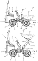
- FIGS. 1 to 4 illustrate a compact dumper 1 in accordance with one possible embodiment of the present invention.
- the dumper 1 comprises an articulated main body 2 formed by a front section 2a and a rear section 2b.
- the front section 2a is pivotally coupled to the rear section 2b by a hinge in order to enable the dumper 1 to be steered in use.
- the front section 2a is provided with a front axle 3 including first and second front wheels 3a, 3b, and the rear section 2b is provided with a rear axle 4 including first and second rear wheels 4a, 4b.
- the rear section 2b of the dumper 1 comprises an operator station 6 including a seat 7 and controls 8 (including a steering wheel, accelerator and brake controls, as well as other control elements which are described in more detail below) by which the dumper 1 may be controlled in use.
- the rear section 2b further comprises a drive system 9, optionally including a combustion engine.
- the drive system 9 is connected to the rear axle 4 via a transmission (and optionally also to the front axle 3) and is operable to drive the wheels 3a, 3b, 4a, 4b of the dumper 1 such that the dumper 1 is self-propelling in use.
- the front section 2a comprises a skip 10 that is located directly above the front axle 3 and configured for carrying bulk material.
- the skip 10 is connected to the main body 2 of the dumper 1 via a skip deployment system 11 comprising a plurality of rigid links 12 and hydraulic pistons 13.
- the skip deployment system 11 is operable to move the skip 10 relative to the main body 2 of the dumper 1 between a lowered position (illustrated in Figure 1 ) and a raised position (illustrated in Figure 2 ), and also to move the skip 10 between a non-tipped position (illustrated in Figures 1 and 2 ) and a tipped position (as indicated by arrow A in Figures 1 and 2 ) in a conventional manner.
- the skip deployment system 11 is powered by a hydraulic actuation system 20, as schematically illustrated in Figure 5 , and is configured to be controlled by an operator using a lever 8a, as described in more detail below.
- the front axle 3 is provided with a track width adjustment system 5 (illustrated schematically in Figure 5 ) that is operable to move the front wheels 3a, 3b with respect to the main body 2 of the dumper 1 in order to vary the track width of the dumper 1 at the front axle 3.
- the track width adjustment system 5 is operable to control movement of the front wheels 3a, 3b between a retracted configuration (illustrated in Figure 3 ) for enabling the dumper 1 to pass through comparatively narrow gaps, and an extended configuration (illustrated in Figure 4 ) for providing increased stability.
- the front wheels 3a, 3b may be movably mounted to the front section 2a of the dumper 1 by any suitable mounting system, including, for example, on extendible chassis members (not shown) that are mounted within and slidingly movable with respect to corresponding housings provided on the front section 2a of the dumper 1.
- the range of track width adjustment provided at each front wheel 3a, 3b is comparatively small, for example approximately 200mm, or less than the width of the wheel.
- the range of track width adjustment may be significantly greater such that the front wheels 3a, 3b can be extended a greater distance out from the front section 2a of the dumper 1.
- the track width adjustment system 5 includes one or more hydraulic pistons 5a that are arranged to control extension and retraction of the front wheels 3a, 3b, as schematically illustrated in Figure 5 .
- the track width adjustment system 5 may include any suitable number and arrangement of hydraulic pistons 5a.
- one or more hydraulic pistons may be connected directly between the front wheels 3a, 3b in order to control the relative distance between the front wheels 3a, 3b; or alternatively each front wheel 3a, 3b may be provided with its own dedicated hydraulic piston(s) which may be connected between the wheel and the front section 2a of the main body 2 of the dumper 1.
- the hydraulic pistons may equally be replaced by one or more hydraulic motors, which may each be configured to operate a rack and pinion system.
- the track width adjustment system 5 is powered by the same hydraulic actuation system 20 that is used to power the skip deployment system 11, as schematically illustrated in Figure 5 , and is also configured to be controlled by an operator using the same lever 8a, as described in more detail below.
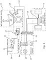
- FIG. 5 schematically illustrates the hydraulic actuation system 20, the track width adjustment system 5, the skip deployment system 11, and an electronic control system 30 used in controlling operation of the track width adjustment system 5.
- the hydraulic actuation system 20 comprises a pump 21, a manual valve 22, and a solenoid valve 23.
- the pump 21 may be driven by any suitable power source (for example by the main drive system 9, or alternatively by a separate electrical motor), and is configured to power movement of the skip deployment system 11 and the track width adjustment system 5.
- the manual valve 22 is configured to control the direction of movement of the skip deployment system 11 and the track width adjustment system 5 (for example skip up/down and tipped/non-tipped, and front wheels extended/retracted). The position of the manual valve 22 is controlled by the lever 8a.
- the lever 8a may be moved by an operator in a first direction in order place the manual valve 22 in a first configuration for raising and/or tipping the skip 10 or extending the front axle 3, or in an opposing second direction in order to place the manual valve 22 in a second configuration for lowering and/or un-tipping the skip 10 or retracting the front axle 3.
- the solenoid valve 23 is connected to the hydraulic pistons 13 of the skip deployment system 11 by a first feeder line 24 and to the hydraulic piston(s) 5a of the track width adjustment system 5 by a second feeder line 25, and is configured to control which one of the skip deployment system 11 and the track width adjustment system 5 is powered by the hydraulic actuation system 20.
- the solenoid valve 23 is configured to default to a first configuration in which the hydraulic actuation system 20 is connected to the skip deployment system 11 via the first feeder line 24 and disconnected from the track width adjustment system 5.
- the solenoid valve 23 is in its first configuration the hydraulic actuation system 20 is placed in a skip deployment mode, in which the skip deployment system 11 will be powered when an operator inputs a command using the lever 8a.
- the skip deployment system 11 may be powered to lift and/or tip the skip 10 if a user pushes the lever 8a forwards and to lower and/or un-tip the skip 10 if the user pulls the lever 8a back while the hydraulic actuation system 20 is in the skip deployment mode.
- the solenoid valve 23 is configured to be selectively switched by the electronic control system 30 into a second configuration in which the hydraulic actuation system 20 is connected to the track width adjustment system 5 via the second feeder line 25 and disconnected from the skip deployment system 11.
- the solenoid valve 23 is in its second configuration the hydraulic actuation system 20 is placed in a track width adjustment mode, in which the track width adjustment system 5 will be powered when an operator inputs a command using the lever 8a.
- the track width adjustment system 5 may be powered to extend the front axle 3 by pushing the front wheels 3a, 3b outwardly if a user pushes the lever 8a forwards and to retract the front axle 3 by pulling the front wheels 3a, 3b inwardly if the user pulls the lever 8a back while the hydraulic actuation system 20 is in the track width adjustment mode.
- the electronic control system 30 comprises a manually operated switch 31 that can be switched by an operator between an open position (or skip deployment position) for commanding activation of the skip deployment system 11 and a closed position (or track width adjustment position) for commanding activation of the track width adjustment system 5.
- the electronic control system 30 further comprises a skip position sensor 32 including a second switch that is configured to automatically switch between an open position when the skip 10 is in an at least partially raised and/or tipped position (for example as illustrated in Figure 2 ) and a closed position when the skip 10 is at least substantially in its fully lowered and non-tipped position (as illustrated in Figure 1 ).
- the skip position sensor 32 may comprise an electronic sensor that is configured to output an electronic signal for controlling the state of the second switch in dependence on a sensed position of the skip 10, or alternatively may comprise a mechanical link that is configured to physically close the second switch when the skip 10 is at least substantially in its fully lowered and non-tipped position.
- the electronic control system 30 only forms a closed circuit when both the first and second switches are closed.
- the electronic control system 30 is configured to switch the solenoid valve 23 from its first configuration into its second configuration (thereby enabling track width adjustment) only if the manual switch 31 has been moved by an operator to the track width adjustment position and the skip position sensor 32 has detected that the skip 10 is at least substantially in its fully lowered and non-tipped position. Operation of the track width adjustment system 5 to increase or decrease the track width of the front axle 3 is therefore prevented in situations in which the skip 10 is at least partially raised and/or at least partially tipped, at which times the dumper 1 may be susceptible to tipping over if the track width adjustment system 5 was operated.
- the skip deployment system 11 and the track width adjustment system 5 are both powered by the same actuation system 20 which can only be operably connected to one of the skip deployment system 11 and the track width adjustment system 5 at any one time, it is also not possible for the track width of the front axle 3 to be adjusted while the skip 10 is being moved relative to the main body 2 of the dumper 1.
- the electronic control system 30 also includes an indicator light 33 that is automatically illuminated when the manual switch 31 has been placed in the track width adjustment position and the skip position sensor 32 has detected that the skip 10 is at least substantially in its fully lowered and non-tipped position.
- the indicator light 33 therefore provides an indication to the operator of when operation of the track width adjustment system 5 is enabled such that the track width adjustment system 5 (and not the skip deployment mechanism 11) will be operated in response to an operator input via the lever 8a.
- the skip deployment system 11 includes at least one hydraulic piston 13 that is operable to raise the skip 10 and at least one piston 13 that is operable to tip the skip 10, as illustrated in Figure 2 .
- the hydraulic actuation system 20 may further comprise an additional valve downstream of the solenoid valve 23 for controlling whether the hydraulic actuation system 20 is connected to the piston(s) that are operable to raise the skip 10 or to the piston(s) that are operable to tip the skip 10.
- Figure 6 schematically illustrates an alternative mechanical track width adjustment prevention system 40 which may be used for inhibiting operation of the track width adjustment system 5 in place of the electronic control system 30 described above in accordance with another possible embodiment of the present invention.
- the same reference numbers have been used in Figure 6 to identify elements having an equivalent function to elements that have already been described in connection with Figure 5 .
- the hydraulic actuation system 20 includes first and second manual valves 22a, 22b which are each connected to a common pump 21.
- the first manual valve 22a is connected to the skip deployment system 11 via a first feeder line 24, and is configured to control the direction of movement of the skip deployment system 11 (for example skip up/down and tipped/non-tipped) in response to a user input via a first lever 8a.
- the second manual valve 22b is connected to the track width adjustment system 5 via a second feeder line 25, and is configured to control the direction of movement of the track width adjustment system 5 (for example front wheels extended/retracted) in response to a user input via a second lever 8b. In this way it is possible for an operator to control the deployment state of the skip 10 and the track width of the front axle 3 individually using separate control elements 8a, 8b.
- the second feeder line 25, extending between the second manual valve 22b and the track width adjustment system 5, is additionally provided with a further valve 42 that is switchable between a closed state for preventing the flow of hydraulic fluid through the second feeder line 25 (thereby preventing the track width of the front axle 3 from being adjusted) and an open state for permitting the flow of hydraulic fluid through the second feeder line 25 (thereby enabling track width adjustment).
- the valve 42 is biased towards its closed state, and so will default to a position in which track width adjustment is prevented.
- the valve 42 is configured to be automatically switched into its closed position, in which track width adjustment is enabled, by a suitable mechanical link.
- valve 42 acts as a mechanical sensor for permitting track width adjustment while the skip 10 is at least substantially in its fully lowered and non-tipped position (as illustrated in Figure 1 ) and preventing track width adjustment when the skip 10 is in an at least partially raised and/or tipped position (for example as illustrated in Figure 2 ).
- track width adjustment is prevented unless the skip is at least substantially in its fully lowered and non-tipped position (as illustrated in Figure 1 ).
- track width adjustment may be permitted while the skip is at least partially raised and/or tipped as long as the skip remains below a threshold position, for example below a threshold height and/or below a threshold tipping angle.
- the threshold position may be set at any suitable level.
- the threshold position may be below 50% or below 25% of the maximum height extension and/or tipping angle of the skip relative to its fully lowered and non-tipped position.
- other positions are also possible.
- the skip deployment system and the track width adjustment system are both powered by a common hydraulic actuation system.
- the skip deployment system and the track width adjustment system could equally be powered by separate actuation systems, which may include separate pumps and be entirely independent of each other.
- one or both of the skip deployment system and the track width adjustment system may be powered by electric motors instead of by a traditional hydraulic actuation system.
- the track width adjustment system may be powered by an electrical actuator
- the dumper may include a control system comprising a sensor for detecting the current position of the skip and a processor that is configured to inhibit a commanded track width adjustment operation in dependence on the detected deployment state of the skip, for example if it is determined that the skip is being moved relative to the main body of the dumper and/or if it is determined that the skip is beyond a threshold position.
- the rear axle may also be configured to have a variable track width.
- a significant increase in stability can be achieved by providing a track width adjustment system at a single axle only (preferably the axle that is located directly beneath the skip) without incurring the additional penalty in complexity, cost and weight associated with providing track width adjustment systems for each of the front and rear axles.
- the skip deployment system may only be configured to tip and un-tip the skip without also being configured to raise and lower the skip.
Landscapes
- Engineering & Computer Science (AREA)
- Mechanical Engineering (AREA)
- Transportation (AREA)
- Chemical & Material Sciences (AREA)
- Combustion & Propulsion (AREA)
- Architecture (AREA)
- Structural Engineering (AREA)
- Vehicle Body Suspensions (AREA)
- Forklifts And Lifting Vehicles (AREA)
- Operation Control Of Excavators (AREA)
- Handcart (AREA)
Description
- The present disclosure relates to a dumper comprising a track width adjustment system that is operable to vary the track width of at least one axle of the dumper.
- Dumpers are vehicles including an integral skip that is designed for carrying bulk material, especially for use on construction sites and in earth moving applications. The skip is provided with a deployment system that is operable to raise and/or tip the skip relative to a main body of the dumper, for example to facilitate loading and unloading of the skip.
- The track width selected when designing a dumper is generally limited for example by the need to facilitate access to difficult-to-reach locations which may require a dumper to pass through comparatively narrow gaps. However, low track width can lead to instability, especially when a dumper is operating on a steep gradient, on uneven or lose terrain, or with the skip in a raised and/or tipped position.
GB2169576A - It is an aim of the present invention to provide a dumper that has increased stability across a range of operating conditions without sacrificing the ability of the dumper to access difficult-to-reach locations.
- According to an aspect of the present invention there is provided a dumper comprising a skip adapted for carrying a load, a deployment system that is operable to raise and/or tip the skip relative to a main body of the dumper, and a track width adjustment system that is operable to vary the track width of the dumper; wherein the dumper comprises a sensor configured to detect the deployment state of the skip, and an electronic control system that is configured to inhibit operation of the track width adjustment system in dependence on the detected deployment state of the skip.
- It will be appreciated that a dumper is a vehicle that is designed to carry bulk material in a skip forming part of the vehicle, especially for use on construction sites and in earth moving applications. It will further be appreciated that the skip is a receptacle that is designed to carry bulk material, typically including a base and a plurality of sidewalls that extend upwardly from the base.
- The variable track width adjustment system allows the track width of the dumper to be adjusted in use such that the dumper is capable of being selectively operated in a narrow or retracted configuration, for example to enable the dumper to pass through comparatively narrow gaps; and in a wide or extended configuration, for example to increase the stability of the dumper when operating on a steep gradient, on uneven or lose terrain, or with the skip in a raised and/or tipped position. However, by configuring the dumper to inhibit operation of the track width adjustment system in dependence on the deployment state of the skip, the dumper of the present invention is able to prevent the track width of the dumper from being adjusted in situations in which adjusting the track width of the dumper might cause the dumper to tip over, for example when the skip is in a raised and/or tipped position or while the skip is moving relative to the main body of the dumper.
- The dumper is preferably self-propelling in use under the action of its own drive system. The drive system may include any suitable drive means, including, for example, a combustion engine and/or one or more electric or hydraulic motors arranged in any suitable manner.
- The present invention may be applied to many different types of dumpers having various different configurations. For example, the invention may be applied to rigid body dumpers and/or to articulated dumpers. In addition, the invention may be applied to dumpers including an operator station comprising one or more control devices (and optionally a seat) from which an operator is able to control operation of the dumper and/or to dumpers that are controlled remotely or that are self-driving.
- The present invention may also be applied to dumpers of various different sizes. However, in a preferred embodiment the dumper may be a compact dumper, for example a dumper having a track width of no more than 2m and preferably no more than 1.5m (the track width being measured while the track width adjustment system is in a retracted state). The present invention is particularly applicable to compact dumpers due to their comparatively low stability, although similar advantages may also be achieved when the invention is applied to larger dumpers.
- The skip may be pivotally connected to the main body of the dumper in order to enable tipping of the skip. Alternatively, or in addition, the skip may be connected to the main body of the dumper by a lifting mechanism in order to enable lifting of the skip. The deployment system may be driven by any suitable actuation system, including, for example, a hydraulic actuation system and/or an actuation system including one or more electric motors.
- The dumper may be a wheeled dumper including at least first and second wheels. Alternatively, or in addition, the dumper may be a tracked dumper including at least first and second tracks. The track width adjustment system may be configured to vary the track width of the dumper by causing relative movement between the first and second wheels and/or between the first and second tracks. The first and second wheels or tracks may be movably mounted to the main body of the dumper in any suitable manner, including, for example, on extendable chassis members that are slidingly movable with respect to the main body of the dumper. The track width adjustment system may be driven by any suitable actuation system, including, for example, a hydraulic actuation system and/or an actuation system including one or more electric motors.
- The dumper may be configured to inhibit operation of the track width adjustment system by preventing the track width adjustment system from being operated to reduce the track width of the dumper in dependence on the deployment state of the skip. The dumper may additionally be configured to prevent the track width adjustment system from increasing the track width of the dumper in dependence on the deployment state of the skip.
- The dumper may be configured to inhibit operation of the track width adjustment system when the skip is beyond a threshold position, and to permit operation of the track width adjustment system when the skip is below the threshold position. The threshold position may comprise a tipping threshold such that operation of the track width adjustment system is inhibited when the skip has been tipped beyond a certain angle relative to the main body of the dumper. Alternatively, or in addition, the threshold position may comprise a height threshold such that operation of the track width adjustment system is inhibited when the skip has been raised above a certain height relative to the main body of the dumper.
- The dumper may be configured to inhibit operation of the track width adjustment system unless the skip is in an at least substantially fully lowered position and/or in an at least substantially fully non-tipped position. However, in other embodiments the dumper may be configured to permit operation of the track width adjustment system while the skip is at least partially raised and/or at least partially tipped, for example while the skip remains below a height threshold and/or a tipping threshold.
- The dumper may be configured to inhibit operation of the track width adjustment system while the skip is being moved relative to the main body of the dumper, and to permit operation of the track width adjustment system while the skip is not being moved relative to the main body of the dumper.
- The dumper comprises a sensor configured to detect the deployment state of the skip (for example the position of the skip and/or whether or not the skip is being moved relative to the main body of the dumper), and an electronic control system that is configured to inhibit operation of the track width adjustment system in dependence on the detected deployment state of the skip.
- The dumper may comprise a mechanical track width adjustment prevention system that is configured to inhibit operation of the track width adjustment system in dependence on the deployment state of the skip.
- The dumper may comprise a common control element that is operable by a user to control both the deployment state of the skip and the track width of the dumper, wherein the control element is selectively operable in either a skip deployment mode for controlling the deployment state of the skip or a track width adjustment mode for controlling the track width of the dumper. In this way the parts count and complexity of the dumper may be reduced, and track width adjustment may be prevented while the skip is being moved relative to the main body of the dumper. The control element may, for example, be a lever. The mode selection may be controlled, for example, using a manual switch.
- The dumper may comprise a common actuation system that is operable to control both the deployment state of the skip and the track width of the dumper, wherein the actuation system is selectively switchable between a skip deployment mode for controlling the deployment state of the skip and a track width adjustment mode for controlling the track width of the dumper. In this way the parts count and complexity of the dumper may be reduced, and track width adjustment may be prevented while the skip is being moved relative to the main body of the dumper. The common actuation system may be a hydraulic actuation system. The common actuation system may comprise a valve that is operable to selectively switch the common actuation system between the skip deployment mode and the track width adjustment mode. The valve may be a solenoid valve, and may be configured to default to a position corresponding to the skip deployment mode. Alternatively, the skip deployment system and the track width adjustment system may be powered by separate actuation systems, which may be entirely independent of each other.
- The dumper may comprise first and second axles, each of which may be provided with at least first and second wheels or first and second tracks. The track width adjustment system may be configured to only vary the track width of the dumper at a first one of the first and second axles. In this way it may be possible to provide increased stability to the dumper while minimising the weight, complexity and cost of the dumper. The axle having a variable track width may be a front axle or alternatively a rear axle. The axle having a variable track width is preferably the axle that is located below the skip and/or at the same end of the dumper as the skip. In other embodiments the track width adjustment system may alternatively be configured to vary the track width of the dumper at multiple axles, for example at both a front axle and a rear axle, in order to provide maximised stability. It will be appreciated that the term "axle" as used throughout this specification refers to a pair of wheels (or tracks) provided on either side of the dumper. It will further be appreciated that in some cases the wheels (or tracks) of an axle may be mounted separately to each other, and that there is no requirement for wheels (or tracks) to be connected to a common shaft.
- The dumper may comprise a notification system configured to confirm to an operator of the dumper whether track width adjustment is currently enabled or inhibited. The notification system may, for example, comprise a light which is configured to be switched on and off or to change colour in dependence on the availability of the track width adjustment function.
- One or more embodiments of the invention will now be described, by way of example only, with reference to the accompanying drawings, in which:
-
Figures 1 to 4 illustrate a compact dumper in accordance with one possible embodiment of the present invention; -
Figure 5 schematically illustrates an electronic control system of the dumper illustrated inFigures 1 to 4 , and -
Figure 6 schematically illustrates an alternative mechanical control system that may be used in place of the electronic control system illustrated inFigure 5 in accordance with another possible embodiment of the present invention. -
Figures 1 to 4 illustrate acompact dumper 1 in accordance with one possible embodiment of the present invention. - As illustrated in
Figures 1 to 4 , thedumper 1 comprises an articulatedmain body 2 formed by afront section 2a and arear section 2b. Thefront section 2a is pivotally coupled to therear section 2b by a hinge in order to enable thedumper 1 to be steered in use. Thefront section 2a is provided with afront axle 3 including first and secondfront wheels rear section 2b is provided with arear axle 4 including first and secondrear wheels - The
rear section 2b of thedumper 1 comprises anoperator station 6 including aseat 7 and controls 8 (including a steering wheel, accelerator and brake controls, as well as other control elements which are described in more detail below) by which thedumper 1 may be controlled in use. Therear section 2b further comprises adrive system 9, optionally including a combustion engine. Thedrive system 9 is connected to therear axle 4 via a transmission (and optionally also to the front axle 3) and is operable to drive thewheels dumper 1 such that thedumper 1 is self-propelling in use. - The
front section 2a comprises askip 10 that is located directly above thefront axle 3 and configured for carrying bulk material. Theskip 10 is connected to themain body 2 of thedumper 1 via askip deployment system 11 comprising a plurality ofrigid links 12 andhydraulic pistons 13. Theskip deployment system 11 is operable to move theskip 10 relative to themain body 2 of thedumper 1 between a lowered position (illustrated inFigure 1 ) and a raised position (illustrated inFigure 2 ), and also to move theskip 10 between a non-tipped position (illustrated inFigures 1 and 2 ) and a tipped position (as indicated by arrow A inFigures 1 and 2 ) in a conventional manner. Theskip deployment system 11 is powered by ahydraulic actuation system 20, as schematically illustrated inFigure 5 , and is configured to be controlled by an operator using alever 8a, as described in more detail below. - The
front axle 3 is provided with a track width adjustment system 5 (illustrated schematically inFigure 5 ) that is operable to move thefront wheels main body 2 of thedumper 1 in order to vary the track width of thedumper 1 at thefront axle 3. In particular, the trackwidth adjustment system 5 is operable to control movement of thefront wheels Figure 3 ) for enabling thedumper 1 to pass through comparatively narrow gaps, and an extended configuration (illustrated inFigure 4 ) for providing increased stability. Thefront wheels front section 2a of thedumper 1 by any suitable mounting system, including, for example, on extendible chassis members (not shown) that are mounted within and slidingly movable with respect to corresponding housings provided on thefront section 2a of thedumper 1. As shown inFigure 4 , the range of track width adjustment provided at eachfront wheel front wheels front section 2a of thedumper 1. However, it has been found that a significant increase in stability can be achieved with even a modest increase in track width as illustrated inFigure 4 . - The track
width adjustment system 5 includes one or morehydraulic pistons 5a that are arranged to control extension and retraction of thefront wheels Figure 5 . For simplicity only a singlehydraulic piston 5a is illustrated inFigure 5 . However, it will be appreciated that the trackwidth adjustment system 5 may include any suitable number and arrangement ofhydraulic pistons 5a. For example, one or more hydraulic pistons may be connected directly between thefront wheels front wheels front wheel front section 2a of themain body 2 of thedumper 1. In other embodiments the hydraulic pistons may equally be replaced by one or more hydraulic motors, which may each be configured to operate a rack and pinion system. The trackwidth adjustment system 5 is powered by the samehydraulic actuation system 20 that is used to power theskip deployment system 11, as schematically illustrated inFigure 5 , and is also configured to be controlled by an operator using thesame lever 8a, as described in more detail below. -
Figure 5 schematically illustrates thehydraulic actuation system 20, the trackwidth adjustment system 5, theskip deployment system 11, and anelectronic control system 30 used in controlling operation of the trackwidth adjustment system 5. As shown inFigure 5 , thehydraulic actuation system 20 comprises apump 21, amanual valve 22, and asolenoid valve 23. - The
pump 21 may be driven by any suitable power source (for example by themain drive system 9, or alternatively by a separate electrical motor), and is configured to power movement of theskip deployment system 11 and the trackwidth adjustment system 5. Themanual valve 22 is configured to control the direction of movement of theskip deployment system 11 and the track width adjustment system 5 (for example skip up/down and tipped/non-tipped, and front wheels extended/retracted). The position of themanual valve 22 is controlled by thelever 8a. In particular, thelever 8a may be moved by an operator in a first direction in order place themanual valve 22 in a first configuration for raising and/or tipping theskip 10 or extending thefront axle 3, or in an opposing second direction in order to place themanual valve 22 in a second configuration for lowering and/or un-tipping theskip 10 or retracting thefront axle 3. - The
solenoid valve 23 is connected to thehydraulic pistons 13 of theskip deployment system 11 by afirst feeder line 24 and to the hydraulic piston(s) 5a of the trackwidth adjustment system 5 by asecond feeder line 25, and is configured to control which one of theskip deployment system 11 and the trackwidth adjustment system 5 is powered by thehydraulic actuation system 20. - The
solenoid valve 23 is configured to default to a first configuration in which thehydraulic actuation system 20 is connected to theskip deployment system 11 via thefirst feeder line 24 and disconnected from the trackwidth adjustment system 5. When thesolenoid valve 23 is in its first configuration thehydraulic actuation system 20 is placed in a skip deployment mode, in which theskip deployment system 11 will be powered when an operator inputs a command using thelever 8a. For example, theskip deployment system 11 may be powered to lift and/or tip theskip 10 if a user pushes thelever 8a forwards and to lower and/or un-tip theskip 10 if the user pulls thelever 8a back while thehydraulic actuation system 20 is in the skip deployment mode. - However, the
solenoid valve 23 is configured to be selectively switched by theelectronic control system 30 into a second configuration in which thehydraulic actuation system 20 is connected to the trackwidth adjustment system 5 via thesecond feeder line 25 and disconnected from theskip deployment system 11. When thesolenoid valve 23 is in its second configuration thehydraulic actuation system 20 is placed in a track width adjustment mode, in which the trackwidth adjustment system 5 will be powered when an operator inputs a command using thelever 8a. For example, the trackwidth adjustment system 5 may be powered to extend thefront axle 3 by pushing thefront wheels lever 8a forwards and to retract thefront axle 3 by pulling thefront wheels lever 8a back while thehydraulic actuation system 20 is in the track width adjustment mode. - The
electronic control system 30 comprises a manually operatedswitch 31 that can be switched by an operator between an open position (or skip deployment position) for commanding activation of theskip deployment system 11 and a closed position (or track width adjustment position) for commanding activation of the trackwidth adjustment system 5. - The
electronic control system 30 further comprises askip position sensor 32 including a second switch that is configured to automatically switch between an open position when theskip 10 is in an at least partially raised and/or tipped position (for example as illustrated inFigure 2 ) and a closed position when theskip 10 is at least substantially in its fully lowered and non-tipped position (as illustrated inFigure 1 ). Theskip position sensor 32 may comprise an electronic sensor that is configured to output an electronic signal for controlling the state of the second switch in dependence on a sensed position of theskip 10, or alternatively may comprise a mechanical link that is configured to physically close the second switch when theskip 10 is at least substantially in its fully lowered and non-tipped position. Theelectronic control system 30 only forms a closed circuit when both the first and second switches are closed. - In this way, the
electronic control system 30 is configured to switch thesolenoid valve 23 from its first configuration into its second configuration (thereby enabling track width adjustment) only if themanual switch 31 has been moved by an operator to the track width adjustment position and theskip position sensor 32 has detected that theskip 10 is at least substantially in its fully lowered and non-tipped position. Operation of the trackwidth adjustment system 5 to increase or decrease the track width of thefront axle 3 is therefore prevented in situations in which theskip 10 is at least partially raised and/or at least partially tipped, at which times thedumper 1 may be susceptible to tipping over if the trackwidth adjustment system 5 was operated. - In addition, since the
skip deployment system 11 and the trackwidth adjustment system 5 are both powered by thesame actuation system 20 which can only be operably connected to one of theskip deployment system 11 and the trackwidth adjustment system 5 at any one time, it is also not possible for the track width of thefront axle 3 to be adjusted while theskip 10 is being moved relative to themain body 2 of thedumper 1. - As illustrated in
Figure 5 , theelectronic control system 30 also includes anindicator light 33 that is automatically illuminated when themanual switch 31 has been placed in the track width adjustment position and theskip position sensor 32 has detected that theskip 10 is at least substantially in its fully lowered and non-tipped position. The indicator light 33 therefore provides an indication to the operator of when operation of the trackwidth adjustment system 5 is enabled such that the track width adjustment system 5 (and not the skip deployment mechanism 11) will be operated in response to an operator input via thelever 8a. - It will be appreciated that the
skip deployment system 11 includes at least onehydraulic piston 13 that is operable to raise theskip 10 and at least onepiston 13 that is operable to tip theskip 10, as illustrated inFigure 2 . However, for simplicity, only asingle piston 13 of theskip deployment system 20 is illustrated inFigure 5 . Thehydraulic actuation system 20 may further comprise an additional valve downstream of thesolenoid valve 23 for controlling whether thehydraulic actuation system 20 is connected to the piston(s) that are operable to raise theskip 10 or to the piston(s) that are operable to tip theskip 10. -
Figure 6 schematically illustrates an alternative mechanical track widthadjustment prevention system 40 which may be used for inhibiting operation of the trackwidth adjustment system 5 in place of theelectronic control system 30 described above in accordance with another possible embodiment of the present invention. For simplicity the same reference numbers have been used inFigure 6 to identify elements having an equivalent function to elements that have already been described in connection withFigure 5 . - As shown in
Figure 6 , in this alternative embodiment thehydraulic actuation system 20 includes first and secondmanual valves common pump 21. The firstmanual valve 22a is connected to theskip deployment system 11 via afirst feeder line 24, and is configured to control the direction of movement of the skip deployment system 11 (for example skip up/down and tipped/non-tipped) in response to a user input via afirst lever 8a. The secondmanual valve 22b is connected to the trackwidth adjustment system 5 via asecond feeder line 25, and is configured to control the direction of movement of the track width adjustment system 5 (for example front wheels extended/retracted) in response to a user input via asecond lever 8b. In this way it is possible for an operator to control the deployment state of theskip 10 and the track width of thefront axle 3 individually usingseparate control elements - However, the
second feeder line 25, extending between the secondmanual valve 22b and the trackwidth adjustment system 5, is additionally provided with afurther valve 42 that is switchable between a closed state for preventing the flow of hydraulic fluid through the second feeder line 25 (thereby preventing the track width of thefront axle 3 from being adjusted) and an open state for permitting the flow of hydraulic fluid through the second feeder line 25 (thereby enabling track width adjustment). Thevalve 42 is biased towards its closed state, and so will default to a position in which track width adjustment is prevented. However, thevalve 42 is configured to be automatically switched into its closed position, in which track width adjustment is enabled, by a suitable mechanical link. In this way thevalve 42 acts as a mechanical sensor for permitting track width adjustment while theskip 10 is at least substantially in its fully lowered and non-tipped position (as illustrated inFigure 1 ) and preventing track width adjustment when theskip 10 is in an at least partially raised and/or tipped position (for example as illustrated inFigure 2 ). - Two possible embodiments of the present invention have been described above. However, it will be appreciated that many modifications may be made to the above examples without departing from the scope of the present invention as defined in the accompanying claims.
- For example, in each of the above-described embodiments track width adjustment is prevented unless the skip is at least substantially in its fully lowered and non-tipped position (as illustrated in
Figure 1 ). However, in other embodiments track width adjustment may be permitted while the skip is at least partially raised and/or tipped as long as the skip remains below a threshold position, for example below a threshold height and/or below a threshold tipping angle. In this case the threshold position may be set at any suitable level. For example, the threshold position may be below 50% or below 25% of the maximum height extension and/or tipping angle of the skip relative to its fully lowered and non-tipped position. However, other positions are also possible. - Moreover, it will be appreciated that the above-described
electronic control system 30 and mechanical track widthadjustment prevention system 40 are described for illustrative purposes only, and that many other electronic and/or mechanical systems could equally be used to inhibit track width adjustment in dependence on the deployment state of the skip, for example while the skip is being moved relative to the main body of the dumper and/or while the skip is beyond a threshold position. - In the above-described embodiments the skip deployment system and the track width adjustment system are both powered by a common hydraulic actuation system. However, in other embodiments the skip deployment system and the track width adjustment system could equally be powered by separate actuation systems, which may include separate pumps and be entirely independent of each other. In addition, in other embodiments, one or both of the skip deployment system and the track width adjustment system may be powered by electric motors instead of by a traditional hydraulic actuation system. For example, in another embodiment the track width adjustment system may be powered by an electrical actuator, and the dumper may include a control system comprising a sensor for detecting the current position of the skip and a processor that is configured to inhibit a commanded track width adjustment operation in dependence on the detected deployment state of the skip, for example if it is determined that the skip is being moved relative to the main body of the dumper and/or if it is determined that the skip is beyond a threshold position.
- In other embodiments the rear axle may also be configured to have a variable track width. However, it has been found that a significant increase in stability can be achieved by providing a track width adjustment system at a single axle only (preferably the axle that is located directly beneath the skip) without incurring the additional penalty in complexity, cost and weight associated with providing track width adjustment systems for each of the front and rear axles.
- In other embodiments the skip deployment system may only be configured to tip and un-tip the skip without also being configured to raise and lower the skip.
Claims (15)
- A dumper (1) comprising a skip (10) adapted for carrying a load, a deployment system (11) that is operable to raise and/or tip the skip (10) relative to a main body (2) of the dumper (1), and a track width adjustment system (5) that is operable to vary the track width of the dumper (1); wherein the dumper (1) comprises a sensor (32) configured to detect the deployment state of the skip (10), and an electronic control system (30) that is configured to inhibit operation of the track width adjustment system (5) in dependence on the detected deployment state of the skip (10).
- A dumper (1) according to claim 1, wherein the dumper (1) is configured to inhibit operation of the track width adjustment system (5) by preventing the track width adjustment system (5) from being operated to reduce the track width of the dumper (1) and/or by preventing the track width adjustment system (5) from being operated to increase the track width of the dumper (1) in dependence on the deployment state of the skip (10).
- A dumper (1) according to claim 1 or claim 2, wherein the dumper (1) is configured to inhibit operation of the track width adjustment system (5) when the skip (10) is beyond a threshold position, and to permit operation of the track width adjustment system (5) when the skip is below the threshold position.
- A dumper (1) according to claim 3, wherein the dumper (1) is configured to inhibit operation of the track width adjustment system (5) unless the skip (10) is in an at least substantially fully lowered position and/or in an at least substantially fully non-tipped position.
- A dumper (1) according to any preceding claim, wherein the dumper (1) is configured to inhibit operation of the track width adjustment system (5) while the skip (10) is being moved relative to the main body (2) of the dumper (1), and to permit operation of the track width adjustment system (5) while the skip (10) is not being moved relative to the main body (2) of the dumper (1).
- A dumper (1) according to any preceding claim, wherein the dumper (1) comprises a mechanical track width adjustment prevention system (40) that is configured to inhibit operation of the track width adjustment system (5) in dependence on the deployment state of the skip (10).
- A dumper (1) according to any preceding claim, wherein the dumper (1) comprises a common control element that is operable by a user to control both the deployment state of the skip (10) and the track width of the dumper (1), wherein the control element is selectively operable in either a skip deployment mode for controlling the deployment state of the skip (10) or a track width adjustment mode for controlling the track width of the dumper (1).
- A dumper (1) according to any preceding claim, wherein the dumper (1) comprises a common actuation system (20) that is operable to control both the deployment state of the skip (10) and the track width of the dumper (1), wherein the actuation system (20) is selectively switchable between a skip deployment mode for controlling the deployment state of the skip (10) and a track width adjustment mode for controlling the track width of the dumper (1).
- A dumper (1) according to claim 8, wherein the common actuation system (20) is a hydraulic actuation system.
- A dumper (1) according to claim 9, wherein the common actuation system (20) comprises a valve (22) that is operable to selectively switch the common actuation system (20) between the skip deployment mode and the track width adjustment mode.
- A dumper (1) according to any preceding claim, wherein the dumper (1) comprises first and second axles (3, 4), wherein the track width adjustment system (5) is configured to only vary the track width of the dumper (1) at a first one of the first and second axles (3, 4).
- A dumper (1) according to any of claims 1 to 10, wherein the dumper (1) comprises first and second axles (3, 4), wherein the track width adjustment system (5) is configured to vary the track width of the dumper (1) at each of the first and second axles (3, 4).
- A dumper (1) according to any preceding claim, wherein the dumper (1) comprises a notification system configured to confirm to an operator of the dumper (1) whether track width adjustment is currently enabled or inhibited.
- A dumper (1) according to any preceding claim, wherein the dumper (1) is a compact dumper, for example a dumper (1) having a track width of no more than 2m and preferably no more than 1.5m.
- A dumper (1) according to any preceding claim, wherein the dumper (1) is a wheeled dumper.
Applications Claiming Priority (1)
| Application Number | Priority Date | Filing Date | Title |
|---|---|---|---|
| GB1818702.1A GB2579054B (en) | 2018-11-16 | 2018-11-16 | Dumper with variable track width |
Publications (3)
| Publication Number | Publication Date |
|---|---|
| EP3653434A1 EP3653434A1 (en) | 2020-05-20 |
| EP3653434B1 true EP3653434B1 (en) | 2021-12-22 |
| EP3653434B8 EP3653434B8 (en) | 2022-04-27 |
Family
ID=64739979
Family Applications (1)
| Application Number | Title | Priority Date | Filing Date |
|---|---|---|---|
| EP19206496.2A Active EP3653434B8 (en) | 2018-11-16 | 2019-10-31 | Dumper with variable track width |
Country Status (3)
| Country | Link |
|---|---|
| EP (1) | EP3653434B8 (en) |
| ES (1) | ES2909958T3 (en) |
| GB (1) | GB2579054B (en) |
Families Citing this family (1)
| Publication number | Priority date | Publication date | Assignee | Title |
|---|---|---|---|---|
| EP3943341A4 (en) * | 2019-03-19 | 2022-12-14 | Hitachi Construction Machinery Co., Ltd. | DUMP TRUCK LOADING BED LIFTING AND LOWERING DEVICE |
Family Cites Families (8)
| Publication number | Priority date | Publication date | Assignee | Title |
|---|---|---|---|---|
| GB2169576B (en) * | 1985-01-10 | 1989-08-02 | Roughneck Excavators Limited | A dumper barrow |
| US6892124B2 (en) * | 2003-07-31 | 2005-05-10 | Deere & Company | Adjustable axle control |
| JP4925575B2 (en) * | 2004-11-26 | 2012-04-25 | 株式会社小松製作所 | Work vehicle safety circuit |
| US8888122B2 (en) * | 2012-03-19 | 2014-11-18 | Jlg Industries, Inc. | Pivoting axle system |
| GB2512926B (en) * | 2013-04-12 | 2015-08-05 | Univ Dublin City | Electric dumper vehicle |
| EP2899102B1 (en) * | 2014-01-24 | 2018-03-14 | Hitachi Construction Machinery Tierra Co., Ltd. | Construction machine |
| US9388538B2 (en) * | 2014-06-09 | 2016-07-12 | Wirtgen Gmbh | Frame width adjustment by steering |
| US9968023B2 (en) * | 2016-06-07 | 2018-05-15 | Cnh Industrial America Llc | Systems and methods for adjusting wheel spacing of an agricultural implement |
-
2018
- 2018-11-16 GB GB1818702.1A patent/GB2579054B/en active Active
-
2019
- 2019-10-31 EP EP19206496.2A patent/EP3653434B8/en active Active
- 2019-10-31 ES ES19206496T patent/ES2909958T3/en active Active
Also Published As
| Publication number | Publication date |
|---|---|
| EP3653434A1 (en) | 2020-05-20 |
| EP3653434B8 (en) | 2022-04-27 |
| GB2579054A (en) | 2020-06-10 |
| GB2579054B (en) | 2020-12-09 |
| GB201818702D0 (en) | 2019-01-02 |
| ES2909958T3 (en) | 2022-05-11 |
Similar Documents
| Publication | Publication Date | Title |
|---|---|---|
| US5195864A (en) | Hydraulic system for a wheel loader | |
| US7909561B2 (en) | Tow truck with underlift control | |
| CA1056773A (en) | Load moment sensing system for lift trucks | |
| EP2719835B1 (en) | Work vehicle with boom lock system and associated method | |
| WO2016123735A1 (en) | Lifting arrangement for construction machine | |
| AU744334B2 (en) | Transportable lift truck with telescopic lifting arm | |
| AU2012337961A1 (en) | Conveyance vehicle | |
| EP3653434B1 (en) | Dumper with variable track width | |
| US5791860A (en) | Hydraulic platform lift for a truck tailgate | |
| US3381833A (en) | Self-synchronizing load lifting and lowering system for straddle carriers and the like | |
| EP1531141B1 (en) | Piggyback forklift truck | |
| US5816767A (en) | Transport locking system for movable-deck vehicle | |
| US20060180563A1 (en) | Method of operating a machine | |
| EP4324782B1 (en) | Forklift | |
| US6336784B1 (en) | Frame leveling speed control system for an extendible boom vehicle | |
| US10005381B2 (en) | Side-loading liftgate having integrated stabilizer leg | |
| US2707059A (en) | Power loader and shovel | |
| EP2377806B1 (en) | Forklift truck | |
| JPH02158432A (en) | Safety device for vehicle transport truck | |
| EP2674386B1 (en) | A forklift truck with load-dependent drive wheel pressure | |
| US20240359612A1 (en) | System for boarding a wheelchair on a vehicle | |
| US5713714A (en) | Tilt cylinder for an underreach assembly | |
| JPS6316587Y2 (en) | ||
| JPH06100298A (en) | Over-load alarm device for elevated spot working vehicle | |
| KR20230040600A (en) | Lifting apparatus of assisting axle for large size vehicle |
Legal Events
| Date | Code | Title | Description |
|---|---|---|---|
| PUAI | Public reference made under article 153(3) epc to a published international application that has entered the european phase |
Free format text: ORIGINAL CODE: 0009012 |
|
| STAA | Information on the status of an ep patent application or granted ep patent |
Free format text: STATUS: THE APPLICATION HAS BEEN PUBLISHED |
|
| AK | Designated contracting states |
Kind code of ref document: A1 Designated state(s): AL AT BE BG CH CY CZ DE DK EE ES FI FR GB GR HR HU IE IS IT LI LT LU LV MC MK MT NL NO PL PT RO RS SE SI SK SM TR |
|
| AX | Request for extension of the european patent |
Extension state: BA ME |
|
| STAA | Information on the status of an ep patent application or granted ep patent |
Free format text: STATUS: REQUEST FOR EXAMINATION WAS MADE |
|
| 17P | Request for examination filed |
Effective date: 20200608 |
|
| RBV | Designated contracting states (corrected) |
Designated state(s): AL AT BE BG CH CY CZ DE DK EE ES FI FR GB GR HR HU IE IS IT LI LT LU LV MC MK MT NL NO PL PT RO RS SE SI SK SM TR |
|
| STAA | Information on the status of an ep patent application or granted ep patent |
Free format text: STATUS: EXAMINATION IS IN PROGRESS |
|
| 17Q | First examination report despatched |
Effective date: 20201211 |
|
| GRAP | Despatch of communication of intention to grant a patent |
Free format text: ORIGINAL CODE: EPIDOSNIGR1 |
|
| STAA | Information on the status of an ep patent application or granted ep patent |
Free format text: STATUS: GRANT OF PATENT IS INTENDED |
|
| RIC1 | Information provided on ipc code assigned before grant |
Ipc: B60P 1/04 20060101AFI20210618BHEP Ipc: B62D 21/14 20060101ALI20210618BHEP Ipc: E02F 9/08 20060101ALI20210618BHEP Ipc: B60B 35/10 20060101ALI20210618BHEP Ipc: B62D 21/18 20060101ALI20210618BHEP Ipc: B62D 49/06 20060101ALI20210618BHEP Ipc: E02F 9/02 20060101ALI20210618BHEP Ipc: B60P 1/16 20060101ALN20210618BHEP |
|
| RIC1 | Information provided on ipc code assigned before grant |
Ipc: B60P 1/04 20060101AFI20210628BHEP Ipc: B62D 21/14 20060101ALI20210628BHEP Ipc: E02F 9/08 20060101ALI20210628BHEP Ipc: B60B 35/10 20060101ALI20210628BHEP Ipc: B62D 21/18 20060101ALI20210628BHEP Ipc: B62D 49/06 20060101ALI20210628BHEP Ipc: E02F 9/02 20060101ALI20210628BHEP Ipc: B60P 1/16 20060101ALN20210628BHEP |
|
| INTG | Intention to grant announced |
Effective date: 20210712 |
|
| GRAS | Grant fee paid |
Free format text: ORIGINAL CODE: EPIDOSNIGR3 |
|
| GRAA | (expected) grant |
Free format text: ORIGINAL CODE: 0009210 |
|
| STAA | Information on the status of an ep patent application or granted ep patent |
Free format text: STATUS: THE PATENT HAS BEEN GRANTED |
|
| RBV | Designated contracting states (corrected) |
Designated state(s): AL AT BE BG CH CY CZ DE DK EE ES FI FR GR HR HU IE IS IT LI LT LU LV MC MK MT NL NO PL PT RO RS SE SI SK SM TR |
|
| AK | Designated contracting states |
Kind code of ref document: B1 Designated state(s): AL AT BE BG CH CY CZ DE DK EE ES FI FR GR HR HU IE IS IT LI LT LU LV MC MK MT NL NO PL PT RO RS SE SI SK SM TR |
|
| REG | Reference to a national code |
Ref country code: CH Ref legal event code: EP |
|
| REG | Reference to a national code |
Ref country code: DE Ref legal event code: R096 Ref document number: 602019010256 Country of ref document: DE |
|
| REG | Reference to a national code |
Ref country code: AT Ref legal event code: REF Ref document number: 1456855 Country of ref document: AT Kind code of ref document: T Effective date: 20220115 |
|
| REG | Reference to a national code |
Ref country code: IE Ref legal event code: FG4D |
|
| REG | Reference to a national code |
Ref country code: DE Ref legal event code: R081 Ref document number: 602019010256 Country of ref document: DE Owner name: BELLE ENGINEERING (SHEEN) LIMITED, GB Free format text: FORMER OWNER: BELLE ENGINEERING (SHEEN) LTD., BUXTON, DERBYSHIRE, GB |
|
| REG | Reference to a national code |
Ref country code: CH Ref legal event code: PK Free format text: BERICHTIGUNG B8 |
|
| REG | Reference to a national code |
Ref country code: LT Ref legal event code: MG9D |
|
| RAP4 | Party data changed (patent owner data changed or rights of a patent transferred) |
Owner name: BELLE ENGINEERING (SHEEN) LIMITED |
|
| PG25 | Lapsed in a contracting state [announced via postgrant information from national office to epo] |
Ref country code: RS Free format text: LAPSE BECAUSE OF FAILURE TO SUBMIT A TRANSLATION OF THE DESCRIPTION OR TO PAY THE FEE WITHIN THE PRESCRIBED TIME-LIMIT Effective date: 20211222 Ref country code: LT Free format text: LAPSE BECAUSE OF FAILURE TO SUBMIT A TRANSLATION OF THE DESCRIPTION OR TO PAY THE FEE WITHIN THE PRESCRIBED TIME-LIMIT Effective date: 20211222 Ref country code: FI Free format text: LAPSE BECAUSE OF FAILURE TO SUBMIT A TRANSLATION OF THE DESCRIPTION OR TO PAY THE FEE WITHIN THE PRESCRIBED TIME-LIMIT Effective date: 20211222 Ref country code: BG Free format text: LAPSE BECAUSE OF FAILURE TO SUBMIT A TRANSLATION OF THE DESCRIPTION OR TO PAY THE FEE WITHIN THE PRESCRIBED TIME-LIMIT Effective date: 20220322 |
|
| REG | Reference to a national code |
Ref country code: NL Ref legal event code: MP Effective date: 20211222 |
|
| REG | Reference to a national code |
Ref country code: ES Ref legal event code: FG2A Ref document number: 2909958 Country of ref document: ES Kind code of ref document: T3 Effective date: 20220511 |
|
| PG25 | Lapsed in a contracting state [announced via postgrant information from national office to epo] |
Ref country code: SE Free format text: LAPSE BECAUSE OF FAILURE TO SUBMIT A TRANSLATION OF THE DESCRIPTION OR TO PAY THE FEE WITHIN THE PRESCRIBED TIME-LIMIT Effective date: 20211222 Ref country code: NO Free format text: LAPSE BECAUSE OF FAILURE TO SUBMIT A TRANSLATION OF THE DESCRIPTION OR TO PAY THE FEE WITHIN THE PRESCRIBED TIME-LIMIT Effective date: 20220322 Ref country code: LV Free format text: LAPSE BECAUSE OF FAILURE TO SUBMIT A TRANSLATION OF THE DESCRIPTION OR TO PAY THE FEE WITHIN THE PRESCRIBED TIME-LIMIT Effective date: 20211222 Ref country code: HR Free format text: LAPSE BECAUSE OF FAILURE TO SUBMIT A TRANSLATION OF THE DESCRIPTION OR TO PAY THE FEE WITHIN THE PRESCRIBED TIME-LIMIT Effective date: 20211222 Ref country code: GR Free format text: LAPSE BECAUSE OF FAILURE TO SUBMIT A TRANSLATION OF THE DESCRIPTION OR TO PAY THE FEE WITHIN THE PRESCRIBED TIME-LIMIT Effective date: 20220323 |
|
| PG25 | Lapsed in a contracting state [announced via postgrant information from national office to epo] |
Ref country code: NL Free format text: LAPSE BECAUSE OF FAILURE TO SUBMIT A TRANSLATION OF THE DESCRIPTION OR TO PAY THE FEE WITHIN THE PRESCRIBED TIME-LIMIT Effective date: 20211222 |
|
| PG25 | Lapsed in a contracting state [announced via postgrant information from national office to epo] |
Ref country code: SM Free format text: LAPSE BECAUSE OF FAILURE TO SUBMIT A TRANSLATION OF THE DESCRIPTION OR TO PAY THE FEE WITHIN THE PRESCRIBED TIME-LIMIT Effective date: 20211222 Ref country code: SK Free format text: LAPSE BECAUSE OF FAILURE TO SUBMIT A TRANSLATION OF THE DESCRIPTION OR TO PAY THE FEE WITHIN THE PRESCRIBED TIME-LIMIT Effective date: 20211222 Ref country code: RO Free format text: LAPSE BECAUSE OF FAILURE TO SUBMIT A TRANSLATION OF THE DESCRIPTION OR TO PAY THE FEE WITHIN THE PRESCRIBED TIME-LIMIT Effective date: 20211222 Ref country code: PT Free format text: LAPSE BECAUSE OF FAILURE TO SUBMIT A TRANSLATION OF THE DESCRIPTION OR TO PAY THE FEE WITHIN THE PRESCRIBED TIME-LIMIT Effective date: 20220422 Ref country code: EE Free format text: LAPSE BECAUSE OF FAILURE TO SUBMIT A TRANSLATION OF THE DESCRIPTION OR TO PAY THE FEE WITHIN THE PRESCRIBED TIME-LIMIT Effective date: 20211222 Ref country code: CZ Free format text: LAPSE BECAUSE OF FAILURE TO SUBMIT A TRANSLATION OF THE DESCRIPTION OR TO PAY THE FEE WITHIN THE PRESCRIBED TIME-LIMIT Effective date: 20211222 |
|
| PG25 | Lapsed in a contracting state [announced via postgrant information from national office to epo] |
Ref country code: PL Free format text: LAPSE BECAUSE OF FAILURE TO SUBMIT A TRANSLATION OF THE DESCRIPTION OR TO PAY THE FEE WITHIN THE PRESCRIBED TIME-LIMIT Effective date: 20211222 |
|
| REG | Reference to a national code |
Ref country code: DE Ref legal event code: R097 Ref document number: 602019010256 Country of ref document: DE |
|
| PG25 | Lapsed in a contracting state [announced via postgrant information from national office to epo] |
Ref country code: IS Free format text: LAPSE BECAUSE OF FAILURE TO SUBMIT A TRANSLATION OF THE DESCRIPTION OR TO PAY THE FEE WITHIN THE PRESCRIBED TIME-LIMIT Effective date: 20220422 |
|
| PLBE | No opposition filed within time limit |
Free format text: ORIGINAL CODE: 0009261 |
|
| STAA | Information on the status of an ep patent application or granted ep patent |
Free format text: STATUS: NO OPPOSITION FILED WITHIN TIME LIMIT |
|
| PG25 | Lapsed in a contracting state [announced via postgrant information from national office to epo] |
Ref country code: DK Free format text: LAPSE BECAUSE OF FAILURE TO SUBMIT A TRANSLATION OF THE DESCRIPTION OR TO PAY THE FEE WITHIN THE PRESCRIBED TIME-LIMIT Effective date: 20211222 Ref country code: AL Free format text: LAPSE BECAUSE OF FAILURE TO SUBMIT A TRANSLATION OF THE DESCRIPTION OR TO PAY THE FEE WITHIN THE PRESCRIBED TIME-LIMIT Effective date: 20211222 |
|
| 26N | No opposition filed |
Effective date: 20220923 |
|
| PG25 | Lapsed in a contracting state [announced via postgrant information from national office to epo] |
Ref country code: SI Free format text: LAPSE BECAUSE OF FAILURE TO SUBMIT A TRANSLATION OF THE DESCRIPTION OR TO PAY THE FEE WITHIN THE PRESCRIBED TIME-LIMIT Effective date: 20211222 |
|
| PG25 | Lapsed in a contracting state [announced via postgrant information from national office to epo] |
Ref country code: MC Free format text: LAPSE BECAUSE OF FAILURE TO SUBMIT A TRANSLATION OF THE DESCRIPTION OR TO PAY THE FEE WITHIN THE PRESCRIBED TIME-LIMIT Effective date: 20211222 Ref country code: IT Free format text: LAPSE BECAUSE OF FAILURE TO SUBMIT A TRANSLATION OF THE DESCRIPTION OR TO PAY THE FEE WITHIN THE PRESCRIBED TIME-LIMIT Effective date: 20211222 |
|
| REG | Reference to a national code |
Ref country code: CH Ref legal event code: PL |
|
| REG | Reference to a national code |
Ref country code: BE Ref legal event code: MM Effective date: 20221031 |
|
| PG25 | Lapsed in a contracting state [announced via postgrant information from national office to epo] |
Ref country code: LU Free format text: LAPSE BECAUSE OF NON-PAYMENT OF DUE FEES Effective date: 20221031 |
|
| REG | Reference to a national code |
Ref country code: AT Ref legal event code: UEP Ref document number: 1456855 Country of ref document: AT Kind code of ref document: T Effective date: 20211222 |
|
| PG25 | Lapsed in a contracting state [announced via postgrant information from national office to epo] |
Ref country code: LI Free format text: LAPSE BECAUSE OF NON-PAYMENT OF DUE FEES Effective date: 20221031 Ref country code: CH Free format text: LAPSE BECAUSE OF NON-PAYMENT OF DUE FEES Effective date: 20221031 |
|
| PG25 | Lapsed in a contracting state [announced via postgrant information from national office to epo] |
Ref country code: BE Free format text: LAPSE BECAUSE OF NON-PAYMENT OF DUE FEES Effective date: 20221031 |
|
| PG25 | Lapsed in a contracting state [announced via postgrant information from national office to epo] |
Ref country code: IE Free format text: LAPSE BECAUSE OF NON-PAYMENT OF DUE FEES Effective date: 20221031 |
|
| PG25 | Lapsed in a contracting state [announced via postgrant information from national office to epo] |
Ref country code: HU Free format text: LAPSE BECAUSE OF FAILURE TO SUBMIT A TRANSLATION OF THE DESCRIPTION OR TO PAY THE FEE WITHIN THE PRESCRIBED TIME-LIMIT; INVALID AB INITIO Effective date: 20191031 |
|
| PG25 | Lapsed in a contracting state [announced via postgrant information from national office to epo] |
Ref country code: CY Free format text: LAPSE BECAUSE OF FAILURE TO SUBMIT A TRANSLATION OF THE DESCRIPTION OR TO PAY THE FEE WITHIN THE PRESCRIBED TIME-LIMIT Effective date: 20211222 |
|
| PG25 | Lapsed in a contracting state [announced via postgrant information from national office to epo] |
Ref country code: MK Free format text: LAPSE BECAUSE OF FAILURE TO SUBMIT A TRANSLATION OF THE DESCRIPTION OR TO PAY THE FEE WITHIN THE PRESCRIBED TIME-LIMIT Effective date: 20211222 |
|
| PG25 | Lapsed in a contracting state [announced via postgrant information from national office to epo] |
Ref country code: MT Free format text: LAPSE BECAUSE OF FAILURE TO SUBMIT A TRANSLATION OF THE DESCRIPTION OR TO PAY THE FEE WITHIN THE PRESCRIBED TIME-LIMIT Effective date: 20211222 |
|
| PG25 | Lapsed in a contracting state [announced via postgrant information from national office to epo] |
Ref country code: TR Free format text: LAPSE BECAUSE OF FAILURE TO SUBMIT A TRANSLATION OF THE DESCRIPTION OR TO PAY THE FEE WITHIN THE PRESCRIBED TIME-LIMIT Effective date: 20211222 |
|
| PGFP | Annual fee paid to national office [announced via postgrant information from national office to epo] |
Ref country code: DE Payment date: 20251028 Year of fee payment: 7 |
|
| PGFP | Annual fee paid to national office [announced via postgrant information from national office to epo] |
Ref country code: AT Payment date: 20250917 Year of fee payment: 7 |
|
| PGFP | Annual fee paid to national office [announced via postgrant information from national office to epo] |
Ref country code: FR Payment date: 20251027 Year of fee payment: 7 |
|
| PGFP | Annual fee paid to national office [announced via postgrant information from national office to epo] |
Ref country code: ES Payment date: 20251118 Year of fee payment: 7 |