EP3653319A1 - Centrifugal additive manufacturing apparatus and method - Google Patents
Centrifugal additive manufacturing apparatus and method Download PDFInfo
- Publication number
- EP3653319A1 EP3653319A1 EP19205045.8A EP19205045A EP3653319A1 EP 3653319 A1 EP3653319 A1 EP 3653319A1 EP 19205045 A EP19205045 A EP 19205045A EP 3653319 A1 EP3653319 A1 EP 3653319A1
- Authority
- EP
- European Patent Office
- Prior art keywords
- build
- operable
- drum
- solidifiable material
- build drum
- Prior art date
- Legal status (The legal status is an assumption and is not a legal conclusion. Google has not performed a legal analysis and makes no representation as to the accuracy of the status listed.)
- Withdrawn
Links
Images




Classifications
-
- B—PERFORMING OPERATIONS; TRANSPORTING
- B22—CASTING; POWDER METALLURGY
- B22F—WORKING METALLIC POWDER; MANUFACTURE OF ARTICLES FROM METALLIC POWDER; MAKING METALLIC POWDER; APPARATUS OR DEVICES SPECIALLY ADAPTED FOR METALLIC POWDER
- B22F10/00—Additive manufacturing of workpieces or articles from metallic powder
- B22F10/10—Formation of a green body
- B22F10/14—Formation of a green body by jetting of binder onto a bed of metal powder
-
- B—PERFORMING OPERATIONS; TRANSPORTING
- B22—CASTING; POWDER METALLURGY
- B22F—WORKING METALLIC POWDER; MANUFACTURE OF ARTICLES FROM METALLIC POWDER; MAKING METALLIC POWDER; APPARATUS OR DEVICES SPECIALLY ADAPTED FOR METALLIC POWDER
- B22F10/00—Additive manufacturing of workpieces or articles from metallic powder
- B22F10/20—Direct sintering or melting
- B22F10/25—Direct deposition of metal particles, e.g. direct metal deposition [DMD] or laser engineered net shaping [LENS]
-
- B—PERFORMING OPERATIONS; TRANSPORTING
- B22—CASTING; POWDER METALLURGY
- B22F—WORKING METALLIC POWDER; MANUFACTURE OF ARTICLES FROM METALLIC POWDER; MAKING METALLIC POWDER; APPARATUS OR DEVICES SPECIALLY ADAPTED FOR METALLIC POWDER
- B22F12/00—Apparatus or devices specially adapted for additive manufacturing; Auxiliary means for additive manufacturing; Combinations of additive manufacturing apparatus or devices with other processing apparatus or devices
- B22F12/22—Driving means
- B22F12/226—Driving means for rotary motion
-
- B—PERFORMING OPERATIONS; TRANSPORTING
- B22—CASTING; POWDER METALLURGY
- B22F—WORKING METALLIC POWDER; MANUFACTURE OF ARTICLES FROM METALLIC POWDER; MAKING METALLIC POWDER; APPARATUS OR DEVICES SPECIALLY ADAPTED FOR METALLIC POWDER
- B22F12/00—Apparatus or devices specially adapted for additive manufacturing; Auxiliary means for additive manufacturing; Combinations of additive manufacturing apparatus or devices with other processing apparatus or devices
- B22F12/30—Platforms or substrates
- B22F12/37—Rotatable
-
- B—PERFORMING OPERATIONS; TRANSPORTING
- B23—MACHINE TOOLS; METAL-WORKING NOT OTHERWISE PROVIDED FOR
- B23K—SOLDERING OR UNSOLDERING; WELDING; CLADDING OR PLATING BY SOLDERING OR WELDING; CUTTING BY APPLYING HEAT LOCALLY, e.g. FLAME CUTTING; WORKING BY LASER BEAM
- B23K15/00—Electron-beam welding or cutting
- B23K15/0046—Welding
- B23K15/0086—Welding welding for purposes other than joining, e.g. build-up welding
-
- B—PERFORMING OPERATIONS; TRANSPORTING
- B23—MACHINE TOOLS; METAL-WORKING NOT OTHERWISE PROVIDED FOR
- B23K—SOLDERING OR UNSOLDERING; WELDING; CLADDING OR PLATING BY SOLDERING OR WELDING; CUTTING BY APPLYING HEAT LOCALLY, e.g. FLAME CUTTING; WORKING BY LASER BEAM
- B23K15/00—Electron-beam welding or cutting
- B23K15/0046—Welding
- B23K15/0093—Welding characterised by the properties of the materials to be welded
-
- B—PERFORMING OPERATIONS; TRANSPORTING
- B23—MACHINE TOOLS; METAL-WORKING NOT OTHERWISE PROVIDED FOR
- B23K—SOLDERING OR UNSOLDERING; WELDING; CLADDING OR PLATING BY SOLDERING OR WELDING; CUTTING BY APPLYING HEAT LOCALLY, e.g. FLAME CUTTING; WORKING BY LASER BEAM
- B23K26/00—Working by laser beam, e.g. welding, cutting or boring
- B23K26/0006—Working by laser beam, e.g. welding, cutting or boring taking account of the properties of the material involved
-
- B—PERFORMING OPERATIONS; TRANSPORTING
- B23—MACHINE TOOLS; METAL-WORKING NOT OTHERWISE PROVIDED FOR
- B23K—SOLDERING OR UNSOLDERING; WELDING; CLADDING OR PLATING BY SOLDERING OR WELDING; CUTTING BY APPLYING HEAT LOCALLY, e.g. FLAME CUTTING; WORKING BY LASER BEAM
- B23K26/00—Working by laser beam, e.g. welding, cutting or boring
- B23K26/02—Positioning or observing the workpiece, e.g. with respect to the point of impact; Aligning, aiming or focusing the laser beam
- B23K26/06—Shaping the laser beam, e.g. by masks or multi-focusing
- B23K26/062—Shaping the laser beam, e.g. by masks or multi-focusing by direct control of the laser beam
- B23K26/0622—Shaping the laser beam, e.g. by masks or multi-focusing by direct control of the laser beam by shaping pulses
-
- B—PERFORMING OPERATIONS; TRANSPORTING
- B23—MACHINE TOOLS; METAL-WORKING NOT OTHERWISE PROVIDED FOR
- B23K—SOLDERING OR UNSOLDERING; WELDING; CLADDING OR PLATING BY SOLDERING OR WELDING; CUTTING BY APPLYING HEAT LOCALLY, e.g. FLAME CUTTING; WORKING BY LASER BEAM
- B23K26/00—Working by laser beam, e.g. welding, cutting or boring
- B23K26/08—Devices involving relative movement between laser beam and workpiece
- B23K26/082—Scanning systems, i.e. devices involving movement of the laser beam relative to the laser head
-
- B—PERFORMING OPERATIONS; TRANSPORTING
- B23—MACHINE TOOLS; METAL-WORKING NOT OTHERWISE PROVIDED FOR
- B23K—SOLDERING OR UNSOLDERING; WELDING; CLADDING OR PLATING BY SOLDERING OR WELDING; CUTTING BY APPLYING HEAT LOCALLY, e.g. FLAME CUTTING; WORKING BY LASER BEAM
- B23K26/00—Working by laser beam, e.g. welding, cutting or boring
- B23K26/08—Devices involving relative movement between laser beam and workpiece
- B23K26/0823—Devices involving rotation of the workpiece
-
- B—PERFORMING OPERATIONS; TRANSPORTING
- B23—MACHINE TOOLS; METAL-WORKING NOT OTHERWISE PROVIDED FOR
- B23K—SOLDERING OR UNSOLDERING; WELDING; CLADDING OR PLATING BY SOLDERING OR WELDING; CUTTING BY APPLYING HEAT LOCALLY, e.g. FLAME CUTTING; WORKING BY LASER BEAM
- B23K26/00—Working by laser beam, e.g. welding, cutting or boring
- B23K26/12—Working by laser beam, e.g. welding, cutting or boring in a special environment or atmosphere, e.g. in an enclosure
- B23K26/127—Working by laser beam, e.g. welding, cutting or boring in a special environment or atmosphere, e.g. in an enclosure in an enclosure
-
- B—PERFORMING OPERATIONS; TRANSPORTING
- B23—MACHINE TOOLS; METAL-WORKING NOT OTHERWISE PROVIDED FOR
- B23K—SOLDERING OR UNSOLDERING; WELDING; CLADDING OR PLATING BY SOLDERING OR WELDING; CUTTING BY APPLYING HEAT LOCALLY, e.g. FLAME CUTTING; WORKING BY LASER BEAM
- B23K26/00—Working by laser beam, e.g. welding, cutting or boring
- B23K26/14—Working by laser beam, e.g. welding, cutting or boring using a fluid stream, e.g. a jet of gas, in conjunction with the laser beam; Nozzles therefor
-
- B—PERFORMING OPERATIONS; TRANSPORTING
- B23—MACHINE TOOLS; METAL-WORKING NOT OTHERWISE PROVIDED FOR
- B23K—SOLDERING OR UNSOLDERING; WELDING; CLADDING OR PLATING BY SOLDERING OR WELDING; CUTTING BY APPLYING HEAT LOCALLY, e.g. FLAME CUTTING; WORKING BY LASER BEAM
- B23K26/00—Working by laser beam, e.g. welding, cutting or boring
- B23K26/14—Working by laser beam, e.g. welding, cutting or boring using a fluid stream, e.g. a jet of gas, in conjunction with the laser beam; Nozzles therefor
- B23K26/144—Working by laser beam, e.g. welding, cutting or boring using a fluid stream, e.g. a jet of gas, in conjunction with the laser beam; Nozzles therefor the fluid stream containing particles, e.g. powder
-
- B—PERFORMING OPERATIONS; TRANSPORTING
- B23—MACHINE TOOLS; METAL-WORKING NOT OTHERWISE PROVIDED FOR
- B23K—SOLDERING OR UNSOLDERING; WELDING; CLADDING OR PLATING BY SOLDERING OR WELDING; CUTTING BY APPLYING HEAT LOCALLY, e.g. FLAME CUTTING; WORKING BY LASER BEAM
- B23K26/00—Working by laser beam, e.g. welding, cutting or boring
- B23K26/34—Laser welding for purposes other than joining
- B23K26/342—Build-up welding
-
- B—PERFORMING OPERATIONS; TRANSPORTING
- B29—WORKING OF PLASTICS; WORKING OF SUBSTANCES IN A PLASTIC STATE IN GENERAL
- B29C—SHAPING OR JOINING OF PLASTICS; SHAPING OF MATERIAL IN A PLASTIC STATE, NOT OTHERWISE PROVIDED FOR; AFTER-TREATMENT OF THE SHAPED PRODUCTS, e.g. REPAIRING
- B29C41/00—Shaping by coating a mould, core or other substrate, i.e. by depositing material and stripping-off the shaped article; Apparatus therefor
- B29C41/02—Shaping by coating a mould, core or other substrate, i.e. by depositing material and stripping-off the shaped article; Apparatus therefor for making articles of definite length, i.e. discrete articles
- B29C41/04—Rotational or centrifugal casting, i.e. coating the inside of a mould by rotating the mould
- B29C41/042—Rotational or centrifugal casting, i.e. coating the inside of a mould by rotating the mould by rotating a mould around its axis of symmetry
- B29C41/045—Rotational or centrifugal casting, i.e. coating the inside of a mould by rotating the mould by rotating a mould around its axis of symmetry the axis being placed vertically, e.g. spin casting
-
- B—PERFORMING OPERATIONS; TRANSPORTING
- B29—WORKING OF PLASTICS; WORKING OF SUBSTANCES IN A PLASTIC STATE IN GENERAL
- B29C—SHAPING OR JOINING OF PLASTICS; SHAPING OF MATERIAL IN A PLASTIC STATE, NOT OTHERWISE PROVIDED FOR; AFTER-TREATMENT OF THE SHAPED PRODUCTS, e.g. REPAIRING
- B29C64/00—Additive manufacturing, i.e. manufacturing of three-dimensional [3D] objects by additive deposition, additive agglomeration or additive layering, e.g. by 3D printing, stereolithography or selective laser sintering
- B29C64/10—Processes of additive manufacturing
- B29C64/141—Processes of additive manufacturing using only solid materials
- B29C64/153—Processes of additive manufacturing using only solid materials using layers of powder being selectively joined, e.g. by selective laser sintering or melting
-
- B—PERFORMING OPERATIONS; TRANSPORTING
- B29—WORKING OF PLASTICS; WORKING OF SUBSTANCES IN A PLASTIC STATE IN GENERAL
- B29C—SHAPING OR JOINING OF PLASTICS; SHAPING OF MATERIAL IN A PLASTIC STATE, NOT OTHERWISE PROVIDED FOR; AFTER-TREATMENT OF THE SHAPED PRODUCTS, e.g. REPAIRING
- B29C64/00—Additive manufacturing, i.e. manufacturing of three-dimensional [3D] objects by additive deposition, additive agglomeration or additive layering, e.g. by 3D printing, stereolithography or selective laser sintering
- B29C64/10—Processes of additive manufacturing
- B29C64/165—Processes of additive manufacturing using a combination of solid and fluid materials, e.g. a powder selectively bound by a liquid binder, catalyst, inhibitor or energy absorber
-
- B—PERFORMING OPERATIONS; TRANSPORTING
- B29—WORKING OF PLASTICS; WORKING OF SUBSTANCES IN A PLASTIC STATE IN GENERAL
- B29C—SHAPING OR JOINING OF PLASTICS; SHAPING OF MATERIAL IN A PLASTIC STATE, NOT OTHERWISE PROVIDED FOR; AFTER-TREATMENT OF THE SHAPED PRODUCTS, e.g. REPAIRING
- B29C64/00—Additive manufacturing, i.e. manufacturing of three-dimensional [3D] objects by additive deposition, additive agglomeration or additive layering, e.g. by 3D printing, stereolithography or selective laser sintering
- B29C64/20—Apparatus for additive manufacturing; Details thereof or accessories therefor
- B29C64/227—Driving means
- B29C64/241—Driving means for rotary motion
-
- B—PERFORMING OPERATIONS; TRANSPORTING
- B29—WORKING OF PLASTICS; WORKING OF SUBSTANCES IN A PLASTIC STATE IN GENERAL
- B29C—SHAPING OR JOINING OF PLASTICS; SHAPING OF MATERIAL IN A PLASTIC STATE, NOT OTHERWISE PROVIDED FOR; AFTER-TREATMENT OF THE SHAPED PRODUCTS, e.g. REPAIRING
- B29C64/00—Additive manufacturing, i.e. manufacturing of three-dimensional [3D] objects by additive deposition, additive agglomeration or additive layering, e.g. by 3D printing, stereolithography or selective laser sintering
- B29C64/20—Apparatus for additive manufacturing; Details thereof or accessories therefor
- B29C64/245—Platforms or substrates
-
- B—PERFORMING OPERATIONS; TRANSPORTING
- B29—WORKING OF PLASTICS; WORKING OF SUBSTANCES IN A PLASTIC STATE IN GENERAL
- B29C—SHAPING OR JOINING OF PLASTICS; SHAPING OF MATERIAL IN A PLASTIC STATE, NOT OTHERWISE PROVIDED FOR; AFTER-TREATMENT OF THE SHAPED PRODUCTS, e.g. REPAIRING
- B29C64/00—Additive manufacturing, i.e. manufacturing of three-dimensional [3D] objects by additive deposition, additive agglomeration or additive layering, e.g. by 3D printing, stereolithography or selective laser sintering
- B29C64/20—Apparatus for additive manufacturing; Details thereof or accessories therefor
- B29C64/264—Arrangements for irradiation
- B29C64/268—Arrangements for irradiation using laser beams; using electron beams [EB]
-
- B—PERFORMING OPERATIONS; TRANSPORTING
- B29—WORKING OF PLASTICS; WORKING OF SUBSTANCES IN A PLASTIC STATE IN GENERAL
- B29C—SHAPING OR JOINING OF PLASTICS; SHAPING OF MATERIAL IN A PLASTIC STATE, NOT OTHERWISE PROVIDED FOR; AFTER-TREATMENT OF THE SHAPED PRODUCTS, e.g. REPAIRING
- B29C64/00—Additive manufacturing, i.e. manufacturing of three-dimensional [3D] objects by additive deposition, additive agglomeration or additive layering, e.g. by 3D printing, stereolithography or selective laser sintering
- B29C64/30—Auxiliary operations or equipment
- B29C64/307—Handling of material to be used in additive manufacturing
- B29C64/321—Feeding
- B29C64/329—Feeding using hoppers
-
- B—PERFORMING OPERATIONS; TRANSPORTING
- B33—ADDITIVE MANUFACTURING TECHNOLOGY
- B33Y—ADDITIVE MANUFACTURING, i.e. MANUFACTURING OF THREE-DIMENSIONAL [3D] OBJECTS BY ADDITIVE DEPOSITION, ADDITIVE AGGLOMERATION OR ADDITIVE LAYERING, e.g. BY 3D PRINTING, STEREOLITHOGRAPHY OR SELECTIVE LASER SINTERING
- B33Y10/00—Processes of additive manufacturing
-
- B—PERFORMING OPERATIONS; TRANSPORTING
- B22—CASTING; POWDER METALLURGY
- B22F—WORKING METALLIC POWDER; MANUFACTURE OF ARTICLES FROM METALLIC POWDER; MAKING METALLIC POWDER; APPARATUS OR DEVICES SPECIALLY ADAPTED FOR METALLIC POWDER
- B22F12/00—Apparatus or devices specially adapted for additive manufacturing; Auxiliary means for additive manufacturing; Combinations of additive manufacturing apparatus or devices with other processing apparatus or devices
- B22F12/40—Radiation means
- B22F12/44—Radiation means characterised by the configuration of the radiation means
- B22F12/45—Two or more
-
- B—PERFORMING OPERATIONS; TRANSPORTING
- B22—CASTING; POWDER METALLURGY
- B22F—WORKING METALLIC POWDER; MANUFACTURE OF ARTICLES FROM METALLIC POWDER; MAKING METALLIC POWDER; APPARATUS OR DEVICES SPECIALLY ADAPTED FOR METALLIC POWDER
- B22F12/00—Apparatus or devices specially adapted for additive manufacturing; Auxiliary means for additive manufacturing; Combinations of additive manufacturing apparatus or devices with other processing apparatus or devices
- B22F12/50—Means for feeding of material, e.g. heads
- B22F12/52—Hoppers
-
- B—PERFORMING OPERATIONS; TRANSPORTING
- B22—CASTING; POWDER METALLURGY
- B22F—WORKING METALLIC POWDER; MANUFACTURE OF ARTICLES FROM METALLIC POWDER; MAKING METALLIC POWDER; APPARATUS OR DEVICES SPECIALLY ADAPTED FOR METALLIC POWDER
- B22F12/00—Apparatus or devices specially adapted for additive manufacturing; Auxiliary means for additive manufacturing; Combinations of additive manufacturing apparatus or devices with other processing apparatus or devices
- B22F12/90—Means for process control, e.g. cameras or sensors
-
- B—PERFORMING OPERATIONS; TRANSPORTING
- B22—CASTING; POWDER METALLURGY
- B22F—WORKING METALLIC POWDER; MANUFACTURE OF ARTICLES FROM METALLIC POWDER; MAKING METALLIC POWDER; APPARATUS OR DEVICES SPECIALLY ADAPTED FOR METALLIC POWDER
- B22F5/00—Manufacture of workpieces or articles from metallic powder characterised by the special shape of the product
- B22F5/02—Manufacture of workpieces or articles from metallic powder characterised by the special shape of the product of piston rings
-
- B—PERFORMING OPERATIONS; TRANSPORTING
- B22—CASTING; POWDER METALLURGY
- B22F—WORKING METALLIC POWDER; MANUFACTURE OF ARTICLES FROM METALLIC POWDER; MAKING METALLIC POWDER; APPARATUS OR DEVICES SPECIALLY ADAPTED FOR METALLIC POWDER
- B22F5/00—Manufacture of workpieces or articles from metallic powder characterised by the special shape of the product
- B22F5/10—Manufacture of workpieces or articles from metallic powder characterised by the special shape of the product of articles with cavities or holes, not otherwise provided for in the preceding subgroups
-
- B—PERFORMING OPERATIONS; TRANSPORTING
- B22—CASTING; POWDER METALLURGY
- B22F—WORKING METALLIC POWDER; MANUFACTURE OF ARTICLES FROM METALLIC POWDER; MAKING METALLIC POWDER; APPARATUS OR DEVICES SPECIALLY ADAPTED FOR METALLIC POWDER
- B22F5/00—Manufacture of workpieces or articles from metallic powder characterised by the special shape of the product
- B22F5/10—Manufacture of workpieces or articles from metallic powder characterised by the special shape of the product of articles with cavities or holes, not otherwise provided for in the preceding subgroups
- B22F5/106—Tube or ring forms
-
- B—PERFORMING OPERATIONS; TRANSPORTING
- B33—ADDITIVE MANUFACTURING TECHNOLOGY
- B33Y—ADDITIVE MANUFACTURING, i.e. MANUFACTURING OF THREE-DIMENSIONAL [3D] OBJECTS BY ADDITIVE DEPOSITION, ADDITIVE AGGLOMERATION OR ADDITIVE LAYERING, e.g. BY 3D PRINTING, STEREOLITHOGRAPHY OR SELECTIVE LASER SINTERING
- B33Y30/00—Apparatus for additive manufacturing; Details thereof or accessories therefor
-
- B—PERFORMING OPERATIONS; TRANSPORTING
- B33—ADDITIVE MANUFACTURING TECHNOLOGY
- B33Y—ADDITIVE MANUFACTURING, i.e. MANUFACTURING OF THREE-DIMENSIONAL [3D] OBJECTS BY ADDITIVE DEPOSITION, ADDITIVE AGGLOMERATION OR ADDITIVE LAYERING, e.g. BY 3D PRINTING, STEREOLITHOGRAPHY OR SELECTIVE LASER SINTERING
- B33Y40/00—Auxiliary operations or equipment, e.g. for material handling
-
- Y—GENERAL TAGGING OF NEW TECHNOLOGICAL DEVELOPMENTS; GENERAL TAGGING OF CROSS-SECTIONAL TECHNOLOGIES SPANNING OVER SEVERAL SECTIONS OF THE IPC; TECHNICAL SUBJECTS COVERED BY FORMER USPC CROSS-REFERENCE ART COLLECTIONS [XRACs] AND DIGESTS
- Y02—TECHNOLOGIES OR APPLICATIONS FOR MITIGATION OR ADAPTATION AGAINST CLIMATE CHANGE
- Y02P—CLIMATE CHANGE MITIGATION TECHNOLOGIES IN THE PRODUCTION OR PROCESSING OF GOODS
- Y02P10/00—Technologies related to metal processing
- Y02P10/25—Process efficiency
Definitions
- This invention relates generally to additive manufacturing, and more particularly to methods for curable material handling in additive manufacturing.
- Additive manufacturing is a process in which material is built up piece-by-piece, line-by-line, or layer-by-layer to form a component.
- Additive manufacturing is also referred to by terms such as “layered manufacturing,” “reverse machining,” “direct metal laser melting” (DMLM), and “3-D printing”. Such terms are treated as synonyms for purposes of the present invention.
- a "powder bed” machine One type of additive manufacturing machine is referred to as a "powder bed” machine and includes a build chamber that encloses a mass of powder which is selectively fused by a laser to form a workpiece.
- an additive manufacturing apparatus includes: a build drum, the build drum having a peripheral wall defining a worksurface, the build drum being mounted for rotation about a central axis; a drive mechanism operable to rotate the build drum about the central axis, to hold a solidifiable material on the worksurface by centrifugal force; a material deposition and solidification apparatus, including: a material depositor operable to deposit the solidifiable material on the worksurface; and
- an apparatus operable to selectively solidify the solidifiable material.
- a method of making a workpiece includes: depositing a solidifiable material in a build drum having a peripheral wall defining a worksurface; rotating the build drum about a central axis, to hold the solidifiable material against the worksurface by centrifugal force; and selectively solidifying the solidifiable material in a pattern corresponding to a layer of the workpiece, while the build drum rotates.
- the concept disclosed herein presents an additive manufacturing method and related apparatus in which solidifiable material is deposited on a rotating build drum and held in place by centrifugal force.
- FIGS. 1-3 illustrate schematically an additive manufacturing machine or apparatus 10 suitable for carrying out an additive manufacturing method.
- Basic components of the apparatus 10 include a build drum 12 and a material deposition and solidification apparatus 14.
- the build drum 12 is a generally rigid structure. It includes a floor 16 at its lower end which may be planar. For purposes of convenient description, the floor 16 may be considered to be oriented parallel to an X-Y plane of the apparatus 10, and a direction perpendicular to the X-Y plane is denoted as a Z-direction (X, Y, and Z being three mutually perpendicular directions).
- a peripheral wall 18 defining a worksurface 20 extends upward from the floor 16.
- the peripheral wall 18 is generally a body of revolution.
- the cross-sectional shape of the peripheral wall 18 may be varied to suit a particular component to be produced.
- the peripheral wall 18 is cylindrical and extends generally perpendicular to the floor 16 (i.e., parallel to the Z-axis).
- the peripheral wall 18 could be made as a separate component which is removable from the floor 16.
- the peripheral wall 18 could be made in two or more segments.
- the peripheral wall 18 could be lined with a removable sleeve (not shown) or multiple sleeves stacked or spaced apart that would provide the build surface or surfaces 20. Still another alternative would be to have discrete removable segments secured to the peripheral wall 18 at suitable locations about the perimeter from which to initiate the build .
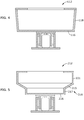
- an alternative peripheral wall 118 extends at an oblique angle to the floor 116, defining a frustoconical shape.
- the peripheral wall 218 has a first section 217 extending vertically from the floor 216 parallel to the Z-direction, a second section 219 extending radially outwards at an angle oblique to the floor 216, and a third section 221 extending parallel to the Z-direction.
- the build drum 12 may include a cover 22, which is a ringshaped element disposed at to the upper edge of the peripheral wall 18. It may be removably secured to the peripheral wall 18, for example using a mechanical joint or fasteners (not shown).
- the purpose of the cover 22 is to retain material in place during a build process.
- the build drum 12 is supported on a base 24 such that it can rotate about central axis 26 which is parallel to the Z-direction. Support is provided by a plurality of bearings 28 between the base 24 and the build drum 12.
- a drive mechanism is provided in the form of a variable-speed electric motor 30. Other mounting and drive systems are possible; the mounting and drive system would be selected as appropriate for the specific application.
- the build drum 12 may be provided with suitable sensors to provide feedback for monitoring or controlling its operation. For example, its rotational speed and/or orientation may be sensed during operation. As one example, the drum 12 may be provided with a rotary encoder or resolver, synchronous or asynchronous. The sensor or sensors may be integral to the drive mechanism. A representative sensor 32 is shown schematically in FIG. 2 .
- the build drum 12 may be used with various types of material deposition and solidification equipment.
- FIGS. 1-3 One example of a material deposition and solidification apparatus 14, shown in FIGS. 1-3 , is similar to that used in "powder bed” additive manufacturing systems. It includes a material supply 34, a recoater 36, a directed energy source 38, and a beam steering apparatus 40.
- Suitable support means are provided for the powder deposition and solidification apparatus 10.
- a bridge 42 spans horizontally above the drum 12, supported by vertical posts 44.
- a column 46 is carried by the bridge 42 and extends down into the drum 12.
- Suitable means are provided for translating the column 46 along the bridge 42.
- a traversing mechanism 48 is depicted schematically in FIGS. 2 and 3 , with the understanding devices such as pneumatic or hydraulic cylinders, ballscrew or linear electric actuators, and so forth, may be used for this purpose.
- the material supply 34 comprises a hopper 50 mounted to the column 46.
- a chute 52 communicates with the hopper 50 and terminates at a material outlet 54.
- the material outlet 54 may have a shape closely conforming to the shape of the peripheral wall 18.
- the hopper 50 is loaded with a supply of solidifiable material "M".
- solidifiable refers to a material which is initially flowable, regardless of its phase (i.e., solid or liquid), which solidifies (i.e. becomes a non-flowable solid) in response to the application of energy, such as radiant energy.
- the apparatus 10 may include multiple material supplies 34 (not shown). These could be arrayed vertically or circumferentially on the column 46. Alternatively, the additional material supplies could be supported by an additional column (not shown) riding on another traversing mechanism (similar to item 48) on a larger beam or additional beam (not shown).
- the solidifiable material M may be a powder of a desired composition (for example, metallic, ceramic, and/or organic powder).
- the powder is "fusible", meaning it is capable of melting and consolidation into a mass upon via application of sufficient energy.
- fusibility is a characteristic of many available polymeric, ceramic, metallic, and organic powders.
- materials such as resins may be used as solidifiable materials M.
- the resin comprises a material which is radiant-energy curable and which is capable of adhering or binding together a filler (if used) in the cured state.
- radiant-energy curable refers to any material which solidifies in response to the application of radiant energy of a particular frequency and energy level.
- the resin may comprise a known type of photopolymer resin containing photo-initiator compounds functioning to trigger a polymerization reaction, causing the resin to change from a liquid state to a solid state.
- the resin may comprise a material which contains a solvent that may be evaporated out by the application of radiant energy.
- the uncured resin may be provided in solid (e.g. granular) or liquid form.
- the composition of the resin may be selected as desired to suit a particular application. Mixtures of different compositions may be used.
- the resin may be selected to have the ability to out-gas or burn off during further processing, such as a sintering process.
- the resin may incorporate a filler.
- the filler may be pre-mixed with resin, then loaded into the material supply 34.
- the filler comprises particles, which are conventionally defined as "a very small bit of matter".
- the filler may comprise any material which is chemically and physically compatible with the selected resin.
- the particles may be regular or irregular in shape, may be uniform or non-uniform in size, and may have variable aspect ratios.
- the particles may take the form of powder, of small spheres or granules, or may be shaped like small rods or fibers.
- composition of the filler including its chemistry and microstructure, may be selected as desired to suit a particular application.
- the filler may be metallic, ceramic, polymeric, and/or organic. Mixtures of different compositions may be used.
- the filler may be fusible as defined above.
- the proportion of filler to resin may be selected to suit a particular application. Generally, any amount of filler may be used so long as the combined material is capable of flowing and being leveled, and there is sufficient resin to hold together the particles of the filler in the cured state.
- the mixture of resin and filler may be referred to as a "slurry".
- the recoater 36 is a rigid, vertically-extending structure that lies on the worksurface 20. It is connected to the chute 52 and/or the hopper 50 so that it can be positioned a precise distance from the worksurface 20, for example by moving the column 46.
- the apparatus 10 may include multiple recoaters 36 (not shown). These could be arrayed vertically or circumferentially on the column 46. Alternatively, the additional recoaters could be supported by an additional column (not shown) riding on another traversing mechanism (similar to item 48) on a larger beam or additional beam (not shown).
- wipers, scrapers, or similar devices could be placed in appropriate positions, for example near the top and bottom of the material outlet 54 or the upper and lower ends of the recoater 36, in order to capture the surplus material.
- the surplus material M can then can be conveyed, e.g., by vacuum, conveyer, or gravity feed, back into the hopper 50 or disposed of.
- scoops 57 are provided near the upper and lower ends of the chute 52 adjacent the material outlet 54. These are connected by piping 59 to a vacuum 61 which pulls the excess material M through the piping 59 and discharges it into a recovery container 63.
- the directed energy source 38 may comprise any device operable to generate a beam of suitable power and other operating characteristics to melt and fuse the material M, or to cure the material M, during the build process which is described in more detail below.
- the directed energy source 38 may be a laser.
- Other directed-energy sources such as electron beam guns are suitable alternatives to a laser.
- the beam steering apparatus 40 may include one or more mirrors, prisms, and/or lenses and provided with suitable actuators, and arranged so that a beam "B" from the directed energy source 38 can be focused to a desired spot size and steered to a desired position in plane coincident with the worksurface 20.
- the beam B may be referred to herein as a "build beam”.
- the apparatus 10 may include multiple directed energy sources 38 (not shown). These could be arrayed vertically or circumferentially on the column 46. Alternatively, the additional directed energy sources could be supported by an additional column (not shown) riding on another traversing mechanism (similar to item 48) on a larger beam or additional beam (not shown).
- the apparatus 10 may include multiple beam steering apparatuses 40 (not shown). These could be arrayed vertically or circumferentially on the column 46. Alternatively, the additional beam steering apparatuses could be supported by an additional column (not shown) riding on another traversing mechanism (similar to item 48) on a larger beam or additional beam (not shown).
- the apparatus 10 may include a controller 56.
- the controller 56 in FIG. 1 is a generalized representation of the hardware and software required to control the operation of the apparatus 10, the build drum 12, the directed energy source 38, the beam steering apparatus, and the various motors and actuators described above.
- the controller 56 may be embodied, for example, by software running on one or more processors embodied in one or more devices such as a programmable logic controller ("PLC") or a microcomputer.
- PLC programmable logic controller
- Such processors may be coupled to sensors and operating components, for example, through wired or wireless connections.
- the same processor or processors may be used to retrieve and analyze sensor data, for statistical analysis, and for feedback control.
- the components of the apparatus 10 may be surrounded by a housing (not shown), which may be used to provide a shielding or inert gas atmosphere.
- a housing (not shown), which may be used to provide a shielding or inert gas atmosphere.
- pressure within the housing could be maintained at a desired level greater than or less than atmospheric.
- the housing could be temperature and/or humidity controlled.
- ventilation of the housing could be controlled based on factors such as a time interval, temperature, humidity, and/or chemical species concentration.
- An exemplary basic build process for a workpiece W using the apparatus described above is as follows. It will be understood that, as a precursor to producing a component and using the apparatus 10, the workpiece W is software modeled as a stack of layers. Each layer may be divided into a grid of pixels. It will be understood that individual layers need not be planar. For example, when manufacturing an annular workpiece, the individual layers may be similar to thin cylinders or other thin annular shapes. The actual workpiece W may be modeled and/or manufactured as a stack of dozens or hundreds of layers. Suitable software modeling processes are known in the art.
- the drum 12 is spun at a selected rotational speed.
- the column 46 is moved so that the material outlet 54 is spaced away from the worksurface 20 by a selected layer increment.
- the layer increment affects the speed of the additive manufacturing process and the resolution of the workpiece W.
- the layer increment may be about 10 to 50 micrometers (0.0003 to 0.002 in.).
- Solidifiable material M is then deposited over the worksurface 20. As the drum 12 rotates, centrifugal force tends to drive the material M against the worksurface 20. As the rotating drum 12 with material M passes by the recoater 36, the recoater 36 spreads the material M across the worksurface 20 to a uniform thickness.
- the leveled material M may be referred to as a "build layer” and the exposed surface thereof may be referred to as a "build surface” 57.
- the rotational speed of the drum 12 is controlled to maintain sufficient centrifugal force to hold the material M against the worksurface 20, or against the underlying material for subsequent layers.
- the rotational speed of the drum 12 may be capped in order to limit the forces on the drum and the material M to acceptable values.
- the speed may vary as the process proceeds. For example, the rotational speed may be varied to give a constant surface speed as material is added and the radius of the exposed build surface 57 decreases. The exact speed required may be computed given knowledge of the allowable forces, the dimensions of the drum 12, and the density of the material M.
- the directed energy source 38 is used to melt a portion of the workpiece W being built.
- the directed energy source 38 emits a beam "B" and the beam steering apparatus 40 is used to steer a focal spot of the build beam B over the exposed material build surface 57 in an appropriate pattern.
- This may be referred to as “selective” solidification, as opposed to nonselective solidification, where the entire build surface 57 would be subjected to radiant energy.
- a small portion of exposed layer of the material M surrounding the focal spot referred to herein as a "weld pool” is heated by the build beam B to a temperature allowing it to sinter or melt, flow, and consolidate.
- the weld pool may be on the order of 100 micrometers (0.004 in.) wide. This step may be referred to as fusing the material M.
- curable material is used instead of a fusible material
- a small portion of exposed layer of the material M surrounding the focal spot solidifies in response to exposure to the build beam B. This step may be referred to as "curing" the material M.
- steering of the weld pool or focal spot may be accomplished by combination of beam steering apparatus 40, timing of pulses of the directed energy source 38, and/or movement of the drum 12.
- the material solidifying operation may be synchronous or asynchronous with the rotation of the drum 12.
- the beam B may be activated continuously while the drum 12 rotates, thus solidifying a ring of material M.
- the beam B may be steered in the Z direction to form the workpiece W in the vertical aspect.
- an axial feature such as a strut or flange, this may be accomplished by activating the build beam B momentarily as the drum 12 rotates.
- the material outlet 54 is moved radially inward by the layer increment, and another layer of material M is applied in a similar thickness.
- the directed energy source 38 again emits a build beam B and the beam steering apparatus 40 is used to steer the focal spot of the build beam B over the exposed material build surface in an appropriate pattern.
- the exposed layer of the material is fused and/or cured so that it can sinter or melt, flow, or otherwise consolidate both within the top layer and with the lower, previously-solidified layer.
- This cycle of moving the material outlet 54, applying material M, and then directed energy solidifying the material M is repeated until the entire workpiece W is complete.
- the process may be continuous or partially continuous. Stated another way, the workpiece W may be built up in a single continuous spiral layer rather than discrete layers.
- the material M may be fused from any direction.
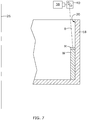
- the build beam B may be projected in a generally axial direction, building up a layer in a generally vertical direction. An example of this is shown in FIG. 7 .
- FIG. 8 illustrates an alternative type of material deposition and solidification apparatus 114.
- This is similar to that used in conventional directed energy deposition ("DED") additive manufacturing systems. It includes a radiant energy source 138 such as a laser or electron beam generator, a beam delivery conduit 140 including internal laser focusing optics, a material feed nozzle 142 coaxial with the beam delivery conduit 140, and a hopper 150 configured to store and meter material to the feed nozzle 142.
- the feed nozzle 142 is structured so that material exits an end opening 144 at the tip of the feed nozzle 142 in a uniform stream concentrically surrounding the laser beam also exiting end opening 144 of feed nozzle 142. The energy from the laser beam will cause the material M to solidify.
- binder jet Yet another type of material solidification process is a "binder jet” process.
- binder jetting uses a chemical binder to bond particles of the material into layers that form a green body of the printed part.
- the green body of the printed part is intended to denote a printed part that has not undergone heat treatment to remove the chemical binder.
- binder jet printing the chemical binder is successively deposited into layers of powder to print the part.
- the chemical binder e.g., a polymeric adhesive
- the chemical binder may be selectively deposited onto a powder in a pattern representative of a layer of the part being printed.
- Each printed layer may be cured (e.g., via heat, light, moisture, solvent evaporation, etc.) after printing to bond the particles of each layer together to form the green body part.
- the chemical binder is removed during post-printing processes (e.g., debinding and sintering) to form a consolidated part.
- FIG. 9 is a simplified diagram of a alternative type of material deposition and solidification apparatus 214 incorporating a binder jet apparatus 238 that may be used to carry out a binder jet process by selectively depositing a binder onto the material M.
- Binder jet devices are generally known in the art.
- the binder jet apparatus 238 includes a printer head 240 including a nozzle array 242.
- the printer head 240 communicates with a fluid binder reservoir 254.
- the entire apparatus 238 is mounted to the column 46 so that it can move in the Z direction, for example by being driven along guide rails 246 by an appropriate actuator (not shown).
- the build process using the material deposition and solidification apparatus 10 is similar to the process described above, the primary difference being that the material M is deposited from the feed nozzle 242 and immediately solidified, as opposed to being laid down in a layer first.
- the method and apparatus described herein has several advantages over the prior art. In particular, it eliminates the bulk, cost, and material waste of conventional powder bed methods.
Landscapes
- Engineering & Computer Science (AREA)
- Chemical & Material Sciences (AREA)
- Materials Engineering (AREA)
- Physics & Mathematics (AREA)
- Optics & Photonics (AREA)
- Manufacturing & Machinery (AREA)
- Mechanical Engineering (AREA)
- Plasma & Fusion (AREA)
- Health & Medical Sciences (AREA)
- Toxicology (AREA)
- Powder Metallurgy (AREA)
Abstract
An additive manufacturing apparatus (10) includes: a build drum (12, 112, 212), the build drum (12, 112, 212) having a peripheral wall defining a worksurface, the build drum (12, 112, 212) being mounted for rotation about a central axis; a drive mechanism (30) operable to rotate the build drum (12, 112, 212) about the central axis, to hold a solidifiable material on the worksurface by centrifugal force; and a material deposition and solidification apparatus (14, 114, 214), including: a material depositor (34) operable to deposit the solidifiable material on the worksurface; and an apparatus operable to selectively solidify the solidifiable material.
Description
- This invention relates generally to additive manufacturing, and more particularly to methods for curable material handling in additive manufacturing.
- Additive manufacturing is a process in which material is built up piece-by-piece, line-by-line, or layer-by-layer to form a component. Additive manufacturing is also referred to by terms such as "layered manufacturing," "reverse machining," "direct metal laser melting" (DMLM), and "3-D printing". Such terms are treated as synonyms for purposes of the present invention.
- One type of additive manufacturing machine is referred to as a "powder bed" machine and includes a build chamber that encloses a mass of powder which is selectively fused by a laser to form a workpiece.
- There is a desire in some applications to make large annular components. One problem with using existing additive manufacturing machines to make annular components is that they require a large, heavy powder bed, even though the majority of the powder will not be used to form a component.
- At least one of these problems is addressed by an additive manufacturing method in which material is deposited and held on a peripheral wall of a rotating drum by centrifugal force.
- According to one aspect of the technology described herein, an additive manufacturing apparatus includes: a build drum, the build drum having a peripheral wall defining a worksurface, the build drum being mounted for rotation about a central axis; a drive mechanism operable to rotate the build drum about the central axis, to hold a solidifiable material on the worksurface by centrifugal force; a material deposition and solidification apparatus, including: a material depositor operable to deposit the solidifiable material on the worksurface; and
- an apparatus operable to selectively solidify the solidifiable material.
- According to another aspect of the technology described herein, a method of making a workpiece includes: depositing a solidifiable material in a build drum having a peripheral wall defining a worksurface; rotating the build drum about a central axis, to hold the solidifiable material against the worksurface by centrifugal force; and selectively solidifying the solidifiable material in a pattern corresponding to a layer of the workpiece, while the build drum rotates.
- The invention may be best understood by reference to the following description taken in conjunction with the accompanying drawing figures in which:
-
FIG. 1 is a schematic top view of an exemplary additive manufacturing apparatus, which is partially broken-away to show certain details; -
FIG. 2 is a schematic, partially-sectioned left side elevation view of the apparatus ofFIG. 1 ; -
FIG. 3 is a schematic, partially-sectioned right side elevation view of the apparatus ofFIG. 1 ; -
FIG. 4 is a schematic cross-section view of an alternative build drum; -
FIG. 5 is a schematic cross-sectional view of another alternative build drum; -
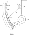
FIG. 6 is an enlarged view of a portion of the apparatus ofFIG. 1 , illustrating an additive manufacturing process; -
FIG. 7 is a schematic, partially-sectioned left side elevation view of the apparatus ofFIG. 1 , showing an alternative additive manufacturing process; and -
FIG. 8 is an enlarged view of a portion of the apparatus ofFIG. 1 , modified with an alternative additive material deposition and solidification apparatus. -
FIG. 9 is an enlarged view of a portion of the apparatus ofFIG. 1 , modified with an alternative additive material deposition and solidification apparatus. - The concept disclosed herein presents an additive manufacturing method and related apparatus in which solidifiable material is deposited on a rotating build drum and held in place by centrifugal force.
- Referring to the drawings wherein identical reference numerals denote the same elements throughout the various views,
FIGS. 1-3 illustrate schematically an additive manufacturing machine orapparatus 10 suitable for carrying out an additive manufacturing method. As will be explained in more detail below, it will be understood that other configurations of equipment may be used to carry out the method described herein. Basic components of theapparatus 10 include abuild drum 12 and a material deposition andsolidification apparatus 14. - The
build drum 12 is a generally rigid structure. It includes afloor 16 at its lower end which may be planar. For purposes of convenient description, thefloor 16 may be considered to be oriented parallel to an X-Y plane of theapparatus 10, and a direction perpendicular to the X-Y plane is denoted as a Z-direction (X, Y, and Z being three mutually perpendicular directions). - A
peripheral wall 18 defining aworksurface 20 extends upward from thefloor 16. Theperipheral wall 18 is generally a body of revolution. The cross-sectional shape of theperipheral wall 18 may be varied to suit a particular component to be produced. In the example shown inFIGS. 1-3 , theperipheral wall 18 is cylindrical and extends generally perpendicular to the floor 16 (i.e., parallel to the Z-axis). Optionally, theperipheral wall 18 could be made as a separate component which is removable from thefloor 16. Optionally theperipheral wall 18 could be made in two or more segments. Optionally, theperipheral wall 18 could be lined with a removable sleeve (not shown) or multiple sleeves stacked or spaced apart that would provide the build surface orsurfaces 20. Still another alternative would be to have discrete removable segments secured to theperipheral wall 18 at suitable locations about the perimeter from which to initiate the build . - In another
exemplary drum 112 shown inFIG. 4 , an alternativeperipheral wall 118 extends at an oblique angle to thefloor 116, defining a frustoconical shape. - In another
exemplary drum 212 shown inFIG. 5 , theperipheral wall 218 has afirst section 217 extending vertically from thefloor 216 parallel to the Z-direction, asecond section 219 extending radially outwards at an angle oblique to thefloor 216, and athird section 221 extending parallel to the Z-direction. - Optionally, the
build drum 12 may include acover 22, which is a ringshaped element disposed at to the upper edge of theperipheral wall 18. It may be removably secured to theperipheral wall 18, for example using a mechanical joint or fasteners (not shown). The purpose of thecover 22 is to retain material in place during a build process. - The
build drum 12 is supported on abase 24 such that it can rotate aboutcentral axis 26 which is parallel to the Z-direction. Support is provided by a plurality ofbearings 28 between thebase 24 and thebuild drum 12. A drive mechanism is provided in the form of a variable-speedelectric motor 30. Other mounting and drive systems are possible; the mounting and drive system would be selected as appropriate for the specific application. - The
build drum 12 may be provided with suitable sensors to provide feedback for monitoring or controlling its operation. For example, its rotational speed and/or orientation may be sensed during operation. As one example, thedrum 12 may be provided with a rotary encoder or resolver, synchronous or asynchronous. The sensor or sensors may be integral to the drive mechanism. Arepresentative sensor 32 is shown schematically inFIG. 2 . - The
build drum 12 may be used with various types of material deposition and solidification equipment. - One example of a material deposition and
solidification apparatus 14, shown inFIGS. 1-3 , is similar to that used in "powder bed" additive manufacturing systems. It includes amaterial supply 34, arecoater 36, a directedenergy source 38, and abeam steering apparatus 40. - Suitable support means are provided for the powder deposition and
solidification apparatus 10. In the illustrated example, abridge 42 spans horizontally above thedrum 12, supported byvertical posts 44. Acolumn 46 is carried by thebridge 42 and extends down into thedrum 12. Suitable means are provided for translating thecolumn 46 along thebridge 42. Atraversing mechanism 48 is depicted schematically inFIGS. 2 and3 , with the understanding devices such as pneumatic or hydraulic cylinders, ballscrew or linear electric actuators, and so forth, may be used for this purpose. - The
material supply 34 comprises ahopper 50 mounted to thecolumn 46. Achute 52 communicates with thehopper 50 and terminates at amaterial outlet 54. Thematerial outlet 54 may have a shape closely conforming to the shape of theperipheral wall 18. Thehopper 50 is loaded with a supply of solidifiable material "M". As used herein, the term "solidifiable" refers to a material which is initially flowable, regardless of its phase (i.e., solid or liquid), which solidifies (i.e. becomes a non-flowable solid) in response to the application of energy, such as radiant energy. - Optionally, the
apparatus 10 may include multiple material supplies 34 (not shown). These could be arrayed vertically or circumferentially on thecolumn 46. Alternatively, the additional material supplies could be supported by an additional column (not shown) riding on another traversing mechanism (similar to item 48) on a larger beam or additional beam (not shown). - In one example, the solidifiable material M may be a powder of a desired composition (for example, metallic, ceramic, and/or organic powder). The powder is "fusible", meaning it is capable of melting and consolidation into a mass upon via application of sufficient energy. For example, fusibility is a characteristic of many available polymeric, ceramic, metallic, and organic powders.
- As an alternative example to powder, materials such as resins may be used as solidifiable materials M. The resin comprises a material which is radiant-energy curable and which is capable of adhering or binding together a filler (if used) in the cured state. As used herein, the term "radiant-energy curable" refers to any material which solidifies in response to the application of radiant energy of a particular frequency and energy level. For example, the resin may comprise a known type of photopolymer resin containing photo-initiator compounds functioning to trigger a polymerization reaction, causing the resin to change from a liquid state to a solid state. Alternatively, the resin may comprise a material which contains a solvent that may be evaporated out by the application of radiant energy. The uncured resin may be provided in solid (e.g. granular) or liquid form.
- The composition of the resin may be selected as desired to suit a particular application. Mixtures of different compositions may be used. The resin may be selected to have the ability to out-gas or burn off during further processing, such as a sintering process.
- The resin may incorporate a filler. The filler may be pre-mixed with resin, then loaded into the
material supply 34. The filler comprises particles, which are conventionally defined as "a very small bit of matter". The filler may comprise any material which is chemically and physically compatible with the selected resin. The particles may be regular or irregular in shape, may be uniform or non-uniform in size, and may have variable aspect ratios. For example, the particles may take the form of powder, of small spheres or granules, or may be shaped like small rods or fibers. - The composition of the filler, including its chemistry and microstructure, may be selected as desired to suit a particular application. For example, the filler may be metallic, ceramic, polymeric, and/or organic. Mixtures of different compositions may be used. The filler may be fusible as defined above.
- The proportion of filler to resin may be selected to suit a particular application. Generally, any amount of filler may be used so long as the combined material is capable of flowing and being leveled, and there is sufficient resin to hold together the particles of the filler in the cured state. The mixture of resin and filler may be referred to as a "slurry".
- Other types of material supplies may be used; for example, instead of a gravity-feed hopper, a powered feeder might be used.
- The
recoater 36 is a rigid, vertically-extending structure that lies on theworksurface 20. It is connected to thechute 52 and/or thehopper 50 so that it can be positioned a precise distance from theworksurface 20, for example by moving thecolumn 46. - Optionally, the
apparatus 10 may include multiple recoaters 36 (not shown). These could be arrayed vertically or circumferentially on thecolumn 46. Alternatively, the additional recoaters could be supported by an additional column (not shown) riding on another traversing mechanism (similar to item 48) on a larger beam or additional beam (not shown). - It is possible that surplus material could be caught between the
floor 16 and thecover 22, where it could be slung onto theworksurface 20. Therefore, optionally, wipers, scrapers, or similar devices could be placed in appropriate positions, for example near the top and bottom of thematerial outlet 54 or the upper and lower ends of therecoater 36, in order to capture the surplus material. The surplus material M can then can be conveyed, e.g., by vacuum, conveyer, or gravity feed, back into thehopper 50 or disposed of. In the example shown inFIG. 2 , scoops 57 are provided near the upper and lower ends of thechute 52 adjacent thematerial outlet 54. These are connected by piping 59 to avacuum 61 which pulls the excess material M through the piping 59 and discharges it into arecovery container 63. - The directed
energy source 38 may comprise any device operable to generate a beam of suitable power and other operating characteristics to melt and fuse the material M, or to cure the material M, during the build process which is described in more detail below. For example, the directedenergy source 38 may be a laser. Other directed-energy sources such as electron beam guns are suitable alternatives to a laser. - The
beam steering apparatus 40 may include one or more mirrors, prisms, and/or lenses and provided with suitable actuators, and arranged so that a beam "B" from the directedenergy source 38 can be focused to a desired spot size and steered to a desired position in plane coincident with theworksurface 20. The beam B may be referred to herein as a "build beam". - Optionally, the
apparatus 10 may include multiple directed energy sources 38 (not shown). These could be arrayed vertically or circumferentially on thecolumn 46. Alternatively, the additional directed energy sources could be supported by an additional column (not shown) riding on another traversing mechanism (similar to item 48) on a larger beam or additional beam (not shown). - Optionally, the
apparatus 10 may include multiple beam steering apparatuses 40 (not shown). These could be arrayed vertically or circumferentially on thecolumn 46. Alternatively, the additional beam steering apparatuses could be supported by an additional column (not shown) riding on another traversing mechanism (similar to item 48) on a larger beam or additional beam (not shown). - The
apparatus 10 may include acontroller 56. Thecontroller 56 inFIG. 1 is a generalized representation of the hardware and software required to control the operation of theapparatus 10, thebuild drum 12, the directedenergy source 38, the beam steering apparatus, and the various motors and actuators described above. Thecontroller 56 may be embodied, for example, by software running on one or more processors embodied in one or more devices such as a programmable logic controller ("PLC") or a microcomputer. Such processors may be coupled to sensors and operating components, for example, through wired or wireless connections. The same processor or processors may be used to retrieve and analyze sensor data, for statistical analysis, and for feedback control. - Optionally, the components of the
apparatus 10 may be surrounded by a housing (not shown), which may be used to provide a shielding or inert gas atmosphere. Optionally, pressure within the housing could be maintained at a desired level greater than or less than atmospheric. Optionally, the housing could be temperature and/or humidity controlled. Optionally, ventilation of the housing could be controlled based on factors such as a time interval, temperature, humidity, and/or chemical species concentration. - An exemplary basic build process for a workpiece W using the apparatus described above is as follows. It will be understood that, as a precursor to producing a component and using the
apparatus 10, the workpiece W is software modeled as a stack of layers. Each layer may be divided into a grid of pixels. It will be understood that individual layers need not be planar. For example, when manufacturing an annular workpiece, the individual layers may be similar to thin cylinders or other thin annular shapes. The actual workpiece W may be modeled and/or manufactured as a stack of dozens or hundreds of layers. Suitable software modeling processes are known in the art. - With reference to
FIG. 6 , initially, thedrum 12 is spun at a selected rotational speed. Thecolumn 46 is moved so that thematerial outlet 54 is spaced away from theworksurface 20 by a selected layer increment. The layer increment affects the speed of the additive manufacturing process and the resolution of the workpiece W. As an example, the layer increment may be about 10 to 50 micrometers (0.0003 to 0.002 in.). Solidifiable material M is then deposited over theworksurface 20. As thedrum 12 rotates, centrifugal force tends to drive the material M against theworksurface 20. As therotating drum 12 with material M passes by therecoater 36, therecoater 36 spreads the material M across theworksurface 20 to a uniform thickness. The leveled material M may be referred to as a "build layer" and the exposed surface thereof may be referred to as a "build surface" 57. - During operation, the rotational speed of the
drum 12 is controlled to maintain sufficient centrifugal force to hold the material M against theworksurface 20, or against the underlying material for subsequent layers. The rotational speed of thedrum 12 may be capped in order to limit the forces on the drum and the material M to acceptable values. The speed may vary as the process proceeds. For example, the rotational speed may be varied to give a constant surface speed as material is added and the radius of the exposedbuild surface 57 decreases. The exact speed required may be computed given knowledge of the allowable forces, the dimensions of thedrum 12, and the density of the material M. - Where a fusible material is used, the directed
energy source 38 is used to melt a portion of the workpiece W being built. The directedenergy source 38 emits a beam "B" and thebeam steering apparatus 40 is used to steer a focal spot of the build beam B over the exposedmaterial build surface 57 in an appropriate pattern. This may be referred to as "selective" solidification, as opposed to nonselective solidification, where theentire build surface 57 would be subjected to radiant energy. A small portion of exposed layer of the material M surrounding the focal spot, referred to herein as a "weld pool" is heated by the build beam B to a temperature allowing it to sinter or melt, flow, and consolidate. As an example, the weld pool may be on the order of 100 micrometers (0.004 in.) wide. This step may be referred to as fusing the material M. - Where a curable material is used instead of a fusible material, a small portion of exposed layer of the material M surrounding the focal spot solidifies in response to exposure to the build beam B. This step may be referred to as "curing" the material M.
- It will be understood that, because the
drum 12 is rotating, steering of the weld pool or focal spot may be accomplished by combination ofbeam steering apparatus 40, timing of pulses of the directedenergy source 38, and/or movement of thedrum 12. The material solidifying operation may be synchronous or asynchronous with the rotation of thedrum 12. For example, if it is desired to create a complete annular feature, the beam B may be activated continuously while thedrum 12 rotates, thus solidifying a ring of material M. The beam B may be steered in the Z direction to form the workpiece W in the vertical aspect. As another example, if it is desired to create an axial feature such as a strut or flange, this may be accomplished by activating the build beam B momentarily as thedrum 12 rotates. - The
material outlet 54 is moved radially inward by the layer increment, and another layer of material M is applied in a similar thickness. The directedenergy source 38 again emits a build beam B and thebeam steering apparatus 40 is used to steer the focal spot of the build beam B over the exposed material build surface in an appropriate pattern. The exposed layer of the material is fused and/or cured so that it can sinter or melt, flow, or otherwise consolidate both within the top layer and with the lower, previously-solidified layer. - This cycle of moving the
material outlet 54, applying material M, and then directed energy solidifying the material M is repeated until the entire workpiece W is complete. - The process may be continuous or partially continuous. Stated another way, the workpiece W may be built up in a single continuous spiral layer rather than discrete layers.
- The material M may be fused from any direction. For example, rather than projecting the build beam B in a generally radial direction and fusing a circumferential layer parallel to the
peripheral wall 18, the build beam B may be projected in a generally axial direction, building up a layer in a generally vertical direction. An example of this is shown inFIG. 7 . - As noted above, the centrifugal drum concept may be used with more than one type of material deposition and solidification apparatus.
FIG. 8 illustrates an alternative type of material deposition andsolidification apparatus 114. This is similar to that used in conventional directed energy deposition ("DED") additive manufacturing systems. It includes aradiant energy source 138 such as a laser or electron beam generator, abeam delivery conduit 140 including internal laser focusing optics, amaterial feed nozzle 142 coaxial with thebeam delivery conduit 140, and ahopper 150 configured to store and meter material to thefeed nozzle 142. Thefeed nozzle 142 is structured so that material exits anend opening 144 at the tip of thefeed nozzle 142 in a uniform stream concentrically surrounding the laser beam also exiting end opening 144 offeed nozzle 142. The energy from the laser beam will cause the material M to solidify. - Yet another type of material solidification process is a "binder jet" process. Unlike laser melting and laser sintering additive manufacturing techniques, which heat the material to consolidate and build layers of the material to form a printed part (e.g., metal or ceramic part), binder jetting uses a chemical binder to bond particles of the material into layers that form a green body of the printed part. As defined herein, the green body of the printed part is intended to denote a printed part that has not undergone heat treatment to remove the chemical binder. In binder jet printing, the chemical binder is successively deposited into layers of powder to print the part. For example, the chemical binder (e.g., a polymeric adhesive) may be selectively deposited onto a powder in a pattern representative of a layer of the part being printed. Each printed layer may be cured (e.g., via heat, light, moisture, solvent evaporation, etc.) after printing to bond the particles of each layer together to form the green body part. After the green body part is fully formed, the chemical binder is removed during post-printing processes (e.g., debinding and sintering) to form a consolidated part.
-
FIG. 9 is a simplified diagram of a alternative type of material deposition andsolidification apparatus 214 incorporating abinder jet apparatus 238 that may be used to carry out a binder jet process by selectively depositing a binder onto the material M. (The same type ofmaterial supply 34 described above may be used in conjunction with the binder jet apparatus 238). Binder jet devices are generally known in the art. In the illustrated embodiment, thebinder jet apparatus 238 includes aprinter head 240 including anozzle array 242. Theprinter head 240 communicates with afluid binder reservoir 254. Theentire apparatus 238 is mounted to thecolumn 46 so that it can move in the Z direction, for example by being driven alongguide rails 246 by an appropriate actuator (not shown). - The build process using the material deposition and
solidification apparatus 10 is similar to the process described above, the primary difference being that the material M is deposited from thefeed nozzle 242 and immediately solidified, as opposed to being laid down in a layer first. - The method and apparatus described herein has several advantages over the prior art. In particular, it eliminates the bulk, cost, and material waste of conventional powder bed methods.
- The foregoing has described a method and apparatus for additive manufacturing using a centrifugal drum. All of the features disclosed in this specification (including any accompanying claims, abstract and drawings), and/or all of the steps of any method or process so disclosed, may be combined in any combination, except combinations where at least some of such features and/or steps are mutually exclusive.
- Each feature disclosed in this specification (including any accompanying claims, abstract and drawings) may be replaced by alternative features serving the same, equivalent or similar purpose, unless expressly stated otherwise. Thus, unless expressly stated otherwise, each feature disclosed is one example only of a generic series of equivalent or similar features.
- The invention is not restricted to the details of the foregoing embodiment(s). The invention extends to any novel one, or any novel combination, of the features disclosed in this specification (including any accompanying claims, abstract and drawings), or to any novel one, or any novel combination, of the steps of any method or process so disclosed.
- Various aspects and embodiments of the invention are defined by the following clauses:
- 1. An additive manufacturing apparatus, comprising:
- a build drum having a peripheral wall defining a worksurface, the build drum being mounted for rotation about a central axis;
- a drive mechanism operable to rotate the build drum about the central axis, so as to hold a solidifiable material on the worksurface by centrifugal force; and
- a material deposition and solidification apparatus, including:
- a material depositor operable to deposit the solidifiable material on the worksurface; and
- an apparatus operable to selectively solidify the solidifiable material.
- 2. The apparatus of clause 1 wherein the apparatus operable to selectively solidify the solidifiable material includes a radiant energy source positioned adjacent to the build drum, and operable to generate and project radiant energy on the solidifiable material.
- 3. The apparatus of clause 1 wherein the apparatus operable to selectively solidify the solidifiable material includes a binder jet printer head.
- 4. The additive manufacturing apparatus of clause 1, wherein the drive mechanism is operable to rotate the build drum at a variable speed.
- 5. The additive manufacturing apparatus of clause 1, further comprising:
- a sensor operable to generate a signal indicative of at least one of: a rotational speed of the build drum and an angular orientation of the build drum relative to the material deposition and solidification apparatus; and
- a controller operable to control the rotational speed of the drive mechanism in response to the signal from the sensor.
- 6. The additive manufacturing apparatus of clause 1, wherein the build drum includes a floor, and the peripheral wall extends from the floor.
- 7. The additive manufacturing apparatus of clause 6, wherein at least a portion of the peripheral wall extends at an oblique angle to the floor.
- 8. The additive manufacturing apparatus of clause 1, wherein the material deposition and solidification apparatus is supported by a translating column which extends downward into the build drum from a bridge which spans above the build drum.
- 9. The apparatus of clause 1 wherein the material deposition and solidification apparatus includes:
- a material depositor operable to deposit the solidifiable material on the worksurface;
- a radiant energy source operable to generate a beam of radiant energy; and
- a beam steering apparatus operable to direct the beam from the radiant energy source on the solidifiable material.
- 10. The apparatus of clause 9 wherein the material depositor includes a hopper communicating with a chute which terminates at a material opening.
- 11. The apparatus of clause 9 wherein the material depositor includes a recoater operable to spread material over the worksurface.
- 12. The apparatus of clause 1 wherein the material deposition and solidification apparatus includes:
- a radiant energy source;
- a beam delivery conduit operable to pass a beam from the radiant energy source therethrough;
- and a material feed nozzle disposed at a distal end of the beam delivery conduit and positioned coaxial a with the beam delivery conduit.
- 13. A method of making a workpiece, comprising:
- depositing a solidifiable material in a build drum having a peripheral wall defining a worksurface;
- rotating the build drum about a central axis, to hold the solidifiable material against the worksurface by centrifugal force;
- selectively solidifying the solidifiable material in a pattern corresponding to a cross-sectional layer of the workpiece, while the build drum rotates.
- 14. The method of clause 13 wherein the step of selectively solidifying includes directing a build beam from a directed energy source to selectively solidify the solidifiable material in a pattern corresponding to a cross-sectional layer of the workpiece, while the build drum rotates.
- 15. The method of clause 13 wherein the step of selectively solidifying includes selectively applying a binder from a binder jet apparatus.
- 16. The method of clause 13 further comprising repeating in a cycle the steps of depositing and solidifying to build up the workpiece in a layer-by layer fashion.
- 17. The method of clause 13 further comprising rotating the build drum at a variable rotational speed so as to maintain a constant surface speed while solidifying the solidifiable material.
- 18. The method of clause 13, wherein the build beam is operated synchronously relative to the rotation of the build drum.
- 19. The method of clause 13, further comprising:
- using a sensor to generate a signal indicative of at least one of: a rotational speed of the build drum and an angular orientation of the build drum relative to the material deposition and solidification apparatus; and
- controlling the rotational speed of the drive mechanism in response to the signal from the sensor.
- 20. The method of clause 13 wherein the solidifiable material is deposited from a material deposition and solidification apparatus which includes:
- a radiant energy source;
- a beam delivery conduit operable to pass a beam from the radiant energy source therethrough;
- and a material feed nozzle disposed at a distal end of the beam delivery conduit and positioned coaxial with the beam delivery conduit.
Claims (15)
- An additive manufacturing apparatus (10), comprising:a build drum (12, 112, 212), the build drum (12, 112, 212) having a peripheral wall defining a worksurface, the build drum (12, 112, 212) being mounted for rotation about a central axis;a drive mechanism (30) operable to rotate the build drum (12, 112, 212) about the central axis, to hold a solidifiable material on the worksurface by centrifugal force; anda material deposition and solidification apparatus (14, 114, 214), including:a material depositor (34) operable to deposit the solidifiable material on the worksurface; andan apparatus (38, 40, 138, 140, 238, 240) operable to selectively solidify the solidifiable material.
- The apparatus (10) of claim 1 wherein the apparatus (38, 40, 138, 140, 238, 240) operable to selectively solidify the solidifiable material includes a radiant energy source (38) positioned adjacent to the build drum (12, 112, 212), and operable to generate and project radiant energy on the solidifiable material.
- The apparatus (10) of claim 1 wherein the apparatus (38, 40, 138, 140, 238, 240) operable to selectively solidify the solidifiable material includes a binder jet printer head (240).
- The additive manufacturing apparatus (10) of claim 1, further comprising:a sensor (32) operable to generate a signal indicative of at least one of: a rotational speed of the build drum (12, 112, 212) and an angular orientation of the build drum (12, 112, 212) relative to the material deposition and solidification apparatus (14, 114, 214); anda controller (56) operable to control the rotational speed of the drive mechanism (30) in response to the signal from the sensor (32).
- The additive manufacturing apparatus (10) of claim 1, wherein the material deposition and solidification apparatus (14, 114, 214) is supported by a translating column (46) which extends downward into the build drum (12, 112, 212) from a bridge (42) which spans above the build drum (12, 112, 212).
- The apparatus (10) of claim 1 wherein the material deposition and solidification apparatus (14, 114, 214) includes:a material depositor (34) operable to deposit the solidifiable material on the worksurface;a radiant energy source (38) operable to generate a beam of radiant energy; anda beam steering apparatus (40) operable to direct the beam from the radiant energy source (38) on the solidifiable material.
- The apparatus (10) of claim 1 wherein the material deposition and solidification apparatus (14, 114, 214) includes:a radiant energy source (38);a beam delivery conduit (140) operable to pass a beam from the radiant energy source (38) therethrough;and a material feed nozzle disposed at a distal end of the beam delivery conduit (140) and positioned coaxial a with the beam delivery conduit (140).
- A method of making a workpiece, comprising:depositing a solidifiable material in a build drum (12, 112, 212) having a peripheral wall defining a worksurface;rotating the build drum about a central axis, to hold the solidifiable material against the worksurface by centrifugal force;selectively solidifying the solidifiable material in a pattern corresponding to a cross-sectional layer of the workpiece, while the drum (12, 112, 212) rotates.
- The method of claim 8 wherein the step of selectively solidifying includes directing a build beam from a directed energy source to selectively solidify the solidifiable material in a pattern corresponding to a cross-sectional layer of the workpiece, while the drum (12, 112, 212) rotates.
- The method of claim 8 wherein the step of selectively solidifying includes selectively applying a binder from a binder jet apparatus.
- The method of claim 8 further comprising repeating in a cycle the steps of depositing and solidifying to build up the workpiece in a layer-by layer fashion.
- The method of claim 8 further comprising rotating the build drum (12, 112, 212) at a variable rotational speed so as to maintain a constant surface speed while solidifying the solidifiable material.
- The method of claim 8, wherein the build beam is operated synchronously relative to the rotation of the build drum (12, 112, 212).
- The method of claim 8, further comprising:using a sensor (32) to generate a signal indicative of at least one of: a rotational speed of the build drum (12, 112, 212) and an angular orientation of the build drum (12, 112, 212) relative to the material deposition and solidification apparatus (14, 114, 214); andcontrolling the rotational speed of the drive mechanism (30) in response to the signal from the sensor (32).
- The method of claim 8 wherein the solidifiable material is deposited from a material deposition and solidification apparatus (14, 114, 214) which includes:a radiant energy source (38);a beam delivery conduit (140) operable to pass a beam from the radiant energy source (38) therethrough;and a material feed nozzle disposed at a distal end of the beam delivery conduit (140) and positioned coaxial with the beam delivery conduit (140).
Applications Claiming Priority (1)
| Application Number | Priority Date | Filing Date | Title |
|---|---|---|---|
| US16/191,796 US20200156290A1 (en) | 2018-11-15 | 2018-11-15 | Centrifugal additive manufacturing apparatus and method |
Publications (1)
| Publication Number | Publication Date |
|---|---|
| EP3653319A1 true EP3653319A1 (en) | 2020-05-20 |
Family
ID=68342773
Family Applications (1)
| Application Number | Title | Priority Date | Filing Date |
|---|---|---|---|
| EP19205045.8A Withdrawn EP3653319A1 (en) | 2018-11-15 | 2019-10-24 | Centrifugal additive manufacturing apparatus and method |
Country Status (3)
| Country | Link |
|---|---|
| US (1) | US20200156290A1 (en) |
| EP (1) | EP3653319A1 (en) |
| CN (1) | CN111186134A (en) |
Cited By (2)
| Publication number | Priority date | Publication date | Assignee | Title |
|---|---|---|---|---|
| WO2021259428A1 (en) * | 2020-06-26 | 2021-12-30 | Fraunhofer-Gesellschaft zur Förderung der angewandten Forschung e.V. | Additive manufacturing method and device |
| EP4678311A1 (en) * | 2024-07-08 | 2026-01-14 | AIRBUS Operations GmbH | Method for additive manufacturing |
Families Citing this family (7)
| Publication number | Priority date | Publication date | Assignee | Title |
|---|---|---|---|---|
| JP7120121B2 (en) * | 2019-03-29 | 2022-08-17 | 新東工業株式会社 | Additive Manufacturing Apparatus and Additive Manufacturing Method |
| US11491703B2 (en) * | 2020-03-25 | 2022-11-08 | Science Applications International Corporation | Printed hollow bodies and systems and methods for printing hollow bodies |
| US11485080B2 (en) | 2020-11-16 | 2022-11-01 | Anton Zavoyskikh | Additive manufacturing apparatus, system and method |
| WO2022158518A1 (en) * | 2021-01-22 | 2022-07-28 | 学校法人慶應義塾 | Additive manufacturing apparatus, and additive manufacturing method |
| CN116917129A (en) * | 2021-03-09 | 2023-10-20 | 戴弗根特技术有限公司 | Rotary additive manufacturing systems and methods |
| US20250176072A1 (en) * | 2022-02-21 | 2025-05-29 | Desktop Metal, Inc. | Build material powder curing station |
| US12202210B1 (en) * | 2024-07-02 | 2025-01-21 | Turbo 3D Llc | Additive manufacturing system |
Citations (4)
| Publication number | Priority date | Publication date | Assignee | Title |
|---|---|---|---|---|
| US5198159A (en) * | 1990-10-09 | 1993-03-30 | Matsushita Electric Works, Ltd. | Process of fabricating three-dimensional objects from a light curable resin liquid |
| US20140147600A1 (en) * | 2012-11-26 | 2014-05-29 | John Dennis Neukirchen | Method and Apparatus for Lining Pipe and Similar Structures |
| US20150251355A1 (en) * | 2012-09-19 | 2015-09-10 | Siemens Aktiengesellschaft | Method and device for powder bed-based additive production of a component |
| US20150306819A1 (en) * | 2012-12-17 | 2015-10-29 | Arcam Ab | Method and apparatus for additive manufacturing |
Family Cites Families (2)
| Publication number | Priority date | Publication date | Assignee | Title |
|---|---|---|---|---|
| US9604412B2 (en) * | 2013-07-12 | 2017-03-28 | Xerox Corporation | Digital manufacturing system for printing three-dimensional objects on a rotating surface |
| KR20180099752A (en) * | 2015-12-31 | 2018-09-05 | 이볼브 애디티브 솔루션스, 아이엔씨. | Construction using cylindrical layers in lamination manufacturing |
-
2018
- 2018-11-15 US US16/191,796 patent/US20200156290A1/en not_active Abandoned
-
2019
- 2019-10-24 EP EP19205045.8A patent/EP3653319A1/en not_active Withdrawn
- 2019-11-14 CN CN201911113154.0A patent/CN111186134A/en active Pending
Patent Citations (4)
| Publication number | Priority date | Publication date | Assignee | Title |
|---|---|---|---|---|
| US5198159A (en) * | 1990-10-09 | 1993-03-30 | Matsushita Electric Works, Ltd. | Process of fabricating three-dimensional objects from a light curable resin liquid |
| US20150251355A1 (en) * | 2012-09-19 | 2015-09-10 | Siemens Aktiengesellschaft | Method and device for powder bed-based additive production of a component |
| US20140147600A1 (en) * | 2012-11-26 | 2014-05-29 | John Dennis Neukirchen | Method and Apparatus for Lining Pipe and Similar Structures |
| US20150306819A1 (en) * | 2012-12-17 | 2015-10-29 | Arcam Ab | Method and apparatus for additive manufacturing |
Cited By (3)
| Publication number | Priority date | Publication date | Assignee | Title |
|---|---|---|---|---|
| WO2021259428A1 (en) * | 2020-06-26 | 2021-12-30 | Fraunhofer-Gesellschaft zur Förderung der angewandten Forschung e.V. | Additive manufacturing method and device |
| US11820047B2 (en) | 2020-06-26 | 2023-11-21 | Fraunhofer-Gesellschaft zur Förderung der angewandten Forschung e.V. | Additive manufacturing method and device |
| EP4678311A1 (en) * | 2024-07-08 | 2026-01-14 | AIRBUS Operations GmbH | Method for additive manufacturing |
Also Published As
| Publication number | Publication date |
|---|---|
| US20200156290A1 (en) | 2020-05-21 |
| CN111186134A (en) | 2020-05-22 |
Similar Documents
| Publication | Publication Date | Title |
|---|---|---|
| EP3653319A1 (en) | Centrifugal additive manufacturing apparatus and method | |
| KR102317567B1 (en) | Additive Manufacturing Using Powder Dispensing | |
| US11833755B2 (en) | Vatless additive manufacturing apparatus and method | |
| CN1678448B (en) | Apparatus and method for manufacturing three-dimensional objects using generative manufacturing methods | |
| TWI781232B (en) | Dispensing system and method of dispensing powder in additive manufacturing apparatus | |
| EP3106288B1 (en) | Additive manufacturing apparatus and method for large components | |
| US9937665B2 (en) | 3D printing using spiral buildup | |
| US20180141267A1 (en) | 3d printing using spiral buildup and high viscosity build materials | |
| US11745289B2 (en) | Additive manufacturing systems and methods including rotating build platform | |
| CN111511487A (en) | Additive manufacturing apparatus and method for large parts | |
| US11420384B2 (en) | Selective curing additive manufacturing method | |
| CN109591289B (en) | Selective Sintering Additive Manufacturing Method | |
| WO2019070377A1 (en) | Additive manufacturing method and apparatus | |
| US20240227024A9 (en) | Powder supply assembly for additive manufacturing | |
| CN114101710A (en) | Additive manufacturing system and method including a rotary adhesive jetting printhead | |
| WO2019023789A1 (en) | Viscous material extrusion method and apparatus for indirect metal three-dimensional printing | |
| CN114585496A (en) | Apparatus and method for additive manufacturing | |
| US11247393B2 (en) | Additive manufacturing systems and methods including rotating binder jet print head | |
| EP3946899A1 (en) | Additive manufacturing | |
| US20190322038A1 (en) | Apparatus and method for fabrication with curable resins by extrusion and photo curing | |
| CN114103110B (en) | Additive manufacturing systems and methods including rotary adhesive jet printheads |
Legal Events
| Date | Code | Title | Description |
|---|---|---|---|
| PUAI | Public reference made under article 153(3) epc to a published international application that has entered the european phase |
Free format text: ORIGINAL CODE: 0009012 |
|
| STAA | Information on the status of an ep patent application or granted ep patent |
Free format text: STATUS: THE APPLICATION HAS BEEN WITHDRAWN |
|
| AK | Designated contracting states |
Kind code of ref document: A1 Designated state(s): AL AT BE BG CH CY CZ DE DK EE ES FI FR GB GR HR HU IE IS IT LI LT LU LV MC MK MT NL NO PL PT RO RS SE SI SK SM TR |
|
| AX | Request for extension of the european patent |
Extension state: BA ME |
|
| 18W | Application withdrawn |
Effective date: 20200513 |