EP3653289A1 - Fluid disperser and fluid dispersing device - Google Patents
Fluid disperser and fluid dispersing device Download PDFInfo
- Publication number
- EP3653289A1 EP3653289A1 EP18831550.1A EP18831550A EP3653289A1 EP 3653289 A1 EP3653289 A1 EP 3653289A1 EP 18831550 A EP18831550 A EP 18831550A EP 3653289 A1 EP3653289 A1 EP 3653289A1
- Authority
- EP
- European Patent Office
- Prior art keywords
- fluid
- wall portion
- disperser
- plate body
- fluid disperser
- Prior art date
- Legal status (The legal status is an assumption and is not a legal conclusion. Google has not performed a legal analysis and makes no representation as to the accuracy of the status listed.)
- Granted
Links
Images



Classifications
-
- B—PERFORMING OPERATIONS; TRANSPORTING
- B01—PHYSICAL OR CHEMICAL PROCESSES OR APPARATUS IN GENERAL
- B01J—CHEMICAL OR PHYSICAL PROCESSES, e.g. CATALYSIS OR COLLOID CHEMISTRY; THEIR RELEVANT APPARATUS
- B01J4/00—Feed or outlet devices; Feed or outlet control devices
- B01J4/001—Feed or outlet devices as such, e.g. feeding tubes
- B01J4/004—Sparger-type elements
-
- F—MECHANICAL ENGINEERING; LIGHTING; HEATING; WEAPONS; BLASTING
- F28—HEAT EXCHANGE IN GENERAL
- F28F—DETAILS OF HEAT-EXCHANGE AND HEAT-TRANSFER APPARATUS, OF GENERAL APPLICATION
- F28F9/00—Casings; Header boxes; Auxiliary supports for elements; Auxiliary members within casings
- F28F9/22—Arrangements for directing heat-exchange media into successive compartments, e.g. arrangements of guide plates
-
- B—PERFORMING OPERATIONS; TRANSPORTING
- B01—PHYSICAL OR CHEMICAL PROCESSES OR APPARATUS IN GENERAL
- B01J—CHEMICAL OR PHYSICAL PROCESSES, e.g. CATALYSIS OR COLLOID CHEMISTRY; THEIR RELEVANT APPARATUS
- B01J4/00—Feed or outlet devices; Feed or outlet control devices
- B01J4/001—Feed or outlet devices as such, e.g. feeding tubes
- B01J4/005—Feed or outlet devices as such, e.g. feeding tubes provided with baffles
-
- B—PERFORMING OPERATIONS; TRANSPORTING
- B01—PHYSICAL OR CHEMICAL PROCESSES OR APPARATUS IN GENERAL
- B01J—CHEMICAL OR PHYSICAL PROCESSES, e.g. CATALYSIS OR COLLOID CHEMISTRY; THEIR RELEVANT APPARATUS
- B01J8/00—Chemical or physical processes in general, conducted in the presence of fluids and solid particles; Apparatus for such processes
- B01J8/02—Chemical or physical processes in general, conducted in the presence of fluids and solid particles; Apparatus for such processes with stationary particles, e.g. in fixed beds
- B01J8/06—Chemical or physical processes in general, conducted in the presence of fluids and solid particles; Apparatus for such processes with stationary particles, e.g. in fixed beds in tube reactors; the solid particles being arranged in tubes
- B01J8/065—Feeding reactive fluids
-
- F—MECHANICAL ENGINEERING; LIGHTING; HEATING; WEAPONS; BLASTING
- F28—HEAT EXCHANGE IN GENERAL
- F28F—DETAILS OF HEAT-EXCHANGE AND HEAT-TRANSFER APPARATUS, OF GENERAL APPLICATION
- F28F9/00—Casings; Header boxes; Auxiliary supports for elements; Auxiliary members within casings
- F28F9/22—Arrangements for directing heat-exchange media into successive compartments, e.g. arrangements of guide plates
- F28F2009/222—Particular guide plates, baffles or deflectors, e.g. having particular orientation relative to an elongated casing or conduit
Definitions
- the present disclosure relates to a fluid disperser and a fluid dispersing device using the fluid disperser.
- Heat treatment devices such as a reactor and a heat exchanger, and pressure vessels typically use a dispersing plate for dispersing an introduced fluid into a plurality of channels located on the downstream side.
- Patent Literature 1 discloses a heat exchanger including a plurality of perforated plates for dispersing introduced recirculated exhaust gas to a plurality of heat transfer pipes provided on the downstream side.
- Patent Literature 1 Japanese Unexamined Patent Application Publication No. 2007-170271
- An object of the present disclosure is to provide a fluid disperser and a fluid dispersing device contributing to an improvement in dispersion performance of a fluid.
- a fluid disperser includes: a plate body installed in a channel, having a first wall portion in a middle region of a first surface facing an upstream side, and provided with a plurality of holes allowing a fluid to flow in from an upstream side to a downstream side; and a second wall portion provided on the first surface and having an inner surface intersecting with a line extending from the middle region to a circumferential edge of the first surface.
- a fluid dispersing device includes: a tubular-shaped portion having an inner curved surface with a channel having a greater diameter on a downstream side than on an upstream side; an opening portion provided in the tubular-shaped portion and allowing a fluid to flow into the channel; and the fluid disperser described above installed in the channel, wherein the first wall portion of the fluid disperser is opposed to an opening of the opening portion, and the second wall portion of the fluid disperser protrudes toward the inner curved surface.
- the present disclosure can provide a fluid disperser and a fluid dispersing device contributing an improvement in dispersion performance of a fluid.
- FIG. 1 is a partial perspective view showing a configuration of a fluid dispersing device according to an embodiment of the present disclosure.
- the fluid dispersing device according to the present disclosure is used for a heat treatment device such as a reactor and a heat exchanger, or a pressure vessel.
- the fluid dispersing device according to the present disclosure disperses an introduced fluid to a plurality of channels provided on the downstream side.
- the fluid dispersing device according to the present embodiment is illustrated with a case presumed to be installed in a reactor.
- reactor refers to a device which uses heat exchange between a reaction fluid and a heat medium, and heats and cools the reaction fluid in a gas or liquid state containing a reaction raw material as a reactant to promote a reaction of the reactant, so as to produce a desirable product.
- the reactor 100 includes a heat exchange unit 110 as a main unit, and a fluid dispersing device 120 as a fluid introduction unit for introducing a fluid to the heat exchange unit 110.
- the fluid introduced to the fluid dispersing device 120 may be either a reaction fluid or a heat medium, and is presumed to be herein a reaction fluid.
- the heat exchange unit 110 produces a product from raw material gas contained in the reaction fluid.
- the heat exchange unit 110 includes a plurality of first heat transfer bodies and a plurality of second heat transfer bodies.
- the first heat transfer bodies and the second heat transfer bodies are each a plate-like member formed of a heat transfer material having high thermal resistance.
- the first heat transfer bodies and the second heat transfer bodies are alternately stacked on one another so as to entirely compose the heat exchange unit 110 having a cuboidal shape.
- the first heat transfer bodies include a plurality of first channels aligned in the Y direction in rows.
- the first channels are in-pipe channels serving as reaction channels in which the reaction fluid introduced through the fluid dispersing device 120 flows.
- the openings 130 on the inlet side of the first channels correspond to the openings at the tips of the pipes facing a third space S3 on the fluid dispersing device 120 side.
- the openings on the outlet side of the first channels are provided at different positions in the heat exchange unit 110, and allow the produced product, for example, to be discharged to the outside.
- the second heat transfer bodies include a plurality of second channels aligned in the Y direction.
- the second channels are in-pipe channels serving as heat medium channels in which the heat medium flows through.
- the openings on the inlet side of the second channels (not shown) are provided to face the fluid dispersing device 120 on the opposite side in the Z direction, so as to introduce the heat medium through a heat medium introduction unit having a shape similar to a tubular-shaped portion 140 of the fluid dispersing device 120.
- the openings on the outlet side of the second channels (not shown) are provided at different positions in the heat exchange unit 110, and allow the heat medium having passed through the second channels to be discharged to the outside.
- the heat exchange unit 101 has a counter flow-type structure in which the reaction fluid in the first channels and the heat medium in the second channels flow in directions opposite to each other.
- the first channels cause received heat, supplied from the heat medium flowing through the second channels, to react with the raw material gas so as to produce a product.
- the fluid dispersing device 120 includes the tubular-shaped portion 140, and a fluid disperser 10 according to the embodiment of the present disclosure and a perforated plate 150 installed in the tubular-shaped portion 140.
- the tubular-shaped portion 140 has two openings opposed to each other in the Z direction, and has an internal space serving as a channel for the reaction fluid.
- One of the openings serves as a first opening portion 140a from which the reaction fluid is introduced, and the other opening serves as a second opening portion 140b from which the reaction fluid is led out toward the heat exchange unit 110.
- FIG. 1 illustrates the second opening portion 140b integrated with the heat exchange unit 110.
- the tubular-shaped portion 140 has a hoop shape in cross section along the X-Y plane perpendicular to an axis which is presumed to be a central axis along the Z direction.
- a channel diameter which is an inner diameter of the tubular-shaped portion 140, gradually increases from the upstream side to the downstream side.
- the channel diameter at the first opening portion 140a is smallest, and the channel diameter at the second opening portion 140b is greatest.
- the tubular-shaped portion 140 has an inner curved surface 140c having a greater channel diameter on the downstream side than on the upstream side
- the first opening portion 140a is connected to a reaction fluid supply unit provided outside the reactor 100 via a supply pipe (not shown).
- An inner diameter of the first opening portion 140a is thus set to be substantially the same as a pipe diameter of the supply pipe.
- the second opening portion 140b has an inner diameter sufficient to entirely cover the side surface of the heat exchange unit 110 provided with a plurality of openings 130.
- the tubular-shaped portion 140 is thus provided with a closed inner space facing the side surface of the heat exchange unit 110 on the reaction fluid introduction side.
- the tubular-shaped portion 140 is detachable or openable with respect to the heat exchange unit 110.
- the detachable or openable tubular-shaped portion 140 allows the fluid disperser 10 and the perforated plate 150 to be installed in the inner space.
- the heat exchange unit 110 can be additionally provided with a catalyst body contributing to the reaction inside the respective first channels.
- the detachable or openable tubular-shaped portion 140 also allows an operator to insert or remove the catalyst body into or from the first channels.
- FIG. 2A is a perspective view showing the fluid disperser 10 as viewed from the side on which the reaction fluid hits.
- FIG. 2B is a perspective view showing the fluid disperser 10 as viewed from the side on which the reaction fluid is led out.
- the fluid disperser 10 includes a disk-like plate body 12.
- the plate body 12 has front and rear main surfaces having a round shape.
- the surface of the plate body 12 on the side on which the reaction fluid hits, which is the main surface facing the upstream side when installed in the channel of the tubular-shaped portion 140, is herein defined as a first surface 12a.
- the surface of the plate body 12 on the side in which the reaction fluid is led out, which is the main surface facing the downstream side when installed in the channel of the tubular-shaped portion 140, is herein defined as a second surface 12b.
- the plate body 12 is provided with a plurality of holes 12c penetrating the first surface 12a and the second surface 12b so as to allow the reaction fluid to flow in from the upstream side to the downstream side.
- the holes 12c are formed not entirely on the entire main plane surface of the plate body 12, particularly not provided in the middle region of the main plane surface.
- the middle region of the plate body 12 not provided with the holes 12c is herein defined as a
- the fluid disperser 10 includes a second wall portion 14 provided on the first surface 12a.
- the second wall portion 14 according to the present embodiment is a hoop-shaped member provided about the middle region serving as a reference of a center.
- the second wall portion 14 is prepared independently of the plate body 12, and can be fixed to the plate body 12 by welding or bonding. Alternatively, the plate body 12 and the second wall portion 14 may be preliminarily and integrally prepared. The conditions for defining the second wall portion 14 are described in detail below.
- the fluid disperser 10 further includes a third wall portion 16 and a fourth wall portion 18 provided on the second surface 12b.
- the third wall portion 16 and the fourth wall portion 18 according to the present embodiment are each a hoop-shaped member provided about the middle region serving as a reference of a center.
- An inner diameter of the third wall portion 16 is greater than an outer diameter of the fourth wall portion 18.
- the third wall portion 16 and the fourth wall portion 18 are both prepared independently of the plate body 12, and can be fixed to the plate body 12 by welding or bonding. Alternatively, the plate body 12 and the third and fourth wall portions 16 and 18 may be preliminarily and integrally prepared. The conditions for defining the third wall portion 16 and the fourth wall portion 18 are described in detail below.
- FIG. 3A is a plan view showing the fluid disperser 10 as viewed from the side provided with the first surface 12a.
- FIG. 3B is a plan view showing the fluid disperser 10 as viewed from the side provided with the second surface 12b.
- the second wall portion 14 has an inner surface 14a intersecting with a line LN extending from the middle region to the circumferential edge of the first surface 12a.
- the middle region used herein is defined as a centroid P 0 .
- the line LN radially extending from the centroid P 0 to the circumferential edge needs to hit at any point along the second wall portion 14. Since the second wall portion 14 according to the present embodiment has a hoop shape in cross section taken along the X-Y plane, the line LN necessarily hits to intersect with the inner surface 14a of the second wall portion 14 at the intersection point P 1 regardless of which direction the line LN extends from the centroid P 0 within the X-Y plane.
- the third wall portion 16 and the fourth wall portion 18 also preferably meet the conditions similar to the above conditions regarding the second wall portion 14.
- the third wall portion 16 has an inner surface 16a intersecting with the line LN extending from the middle region to the circumferential edge of the plate body 12 at the intersection point P 2 .
- the fourth wall portion 18 has an inner surface 18a intersecting with the line LN extending from the middle region to the circumferential edge of the plate body 12 at the intersection point P 3 .
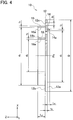
- FIG. 4 is a cross-sectional side view for explaining the dimensional conditions for the fluid disperser 10.
- the plate body 12 has an outer diameter D and a thickness to.
- the holes 12c provided in the plate body 12 have an opening diameter d 0 .
- the second wall portion 14 has a thickness t 1 , an inner diameter d 1 , and a height L 1 from the first surface 12a.
- the third wall portion 16 has a thickness t 2 , an inner diameter d 2 , and a height L 2 from the second surface 12b.
- the fourth wall portion 18 has a thickness t 3 , an inner diameter d 3 , and the same height L 2 from the second surface 12b as the third wall portion 16.
- the thicknesses t 1 , t 2 , and t 3 of the respective walls are preferably, but not necessarily, smaller than the opening diameter do of the holes 12c so as not to increase the number of the holes 12c blocked by these walls.
- the respective conditions for the fluid disperser 10 as defined above are described in more detail below together with the operations of the fluid disperser 10 and the fluid dispersing device 120.
- the perforated plate 150 is a fluid dispersing plate provided with a plurality of holes 150a so as to allow the reaction fluid to flow in from the upstream side to the downstream side. As illustrated in FIG. 1 , the perforated plate 150 is arranged parallel to the plate body 12 of the fluid disperser 10 on the downstream side of the fluid disperser 10 in the channel of the tubular-shaped portion 140. An outer diameter of the perforated plate 150, which varies depending on the position to be located, can be equivalent to the inner diameter of the tubular-shaped portion 140 without being in direct contact with the tubular-shaped portion 140. A thickness of the perforated plate 150 can be equivalent to the thickness to of the plate body 12 of the fluid disperser 10. An opening diameter of the holes 150a provided in the perforated plate 150 can be equivalent to the opening diameter of the holes 12c provided in the plate body 12 of the fluid disperser 10.
- the channel of the tubular-shaped portion 140 is provided with three spaces defined by the fluid disperser 10 and the perforated plate 150.
- a first space S1 is defined between the first opening portion 140a and the fluid disperser 10
- a second space S2 is defined between the fluid disperser 10 and the perforated plate 150
- a third space S3 is defined between the perforated plate 150 and the second opening portion 140b.
- FIG. 1 indicates the reaction fluid R and flowing directions by the solid-white arrows.
- the fluid disperser 10 is preliminarily installed in the channel of the tubular-shaped portion 140 such that the first wall portion 12d in the middle region of the plate body 12 is opposed to the opening of the first opening portion 140a.
- the outer diameter D of the plate body 12 is preliminarily set to be equivalent to the inner diameter of the tubular-shaped portion 140 without being in direct contact with the tubular-shaped portion 140. In other words, a gap is actually present between the circumferential edge of the plate body 12 and the inner surface of the tubular-shaped portion 140 adjacent to the circumferential edge.
- the reaction fluid R1 supplied from the external reaction fluid supply unit flows through the first opening portion 140a into the first space S1 in the tubular-shaped portion 140.
- the flowing reaction fluid R1 hits against the first wall portion 12d of the fluid disperser 10.
- the reaction fluid R2 after hitting flows radially along the first surface 12a, since the first wall portion 12d is provided with no holes 12c.
- the second wall portion 14 is provided on the first surface 12a.
- the second wall portion 14 protrudes from the first surface 12a toward the inner curved surface 140c of the tubular-shaped portion 140.
- the inner curved surface 140c is present on the extension of the inner surface 14a of the second wall portion 14 in the Z direction perpendicular to the first surface 12a.
- the reaction fluid R2 flowing radially along the first surface 12a thus hits against the inner surface 14a of the second wall portion 14.
- the reaction fluid R3 hitting against the inner surface 14a changes the flowing direction so as to flow toward the inner curved surface 140c.
- the reaction fluid hitting against the inner curved surface 140c is divided into two directions.
- reaction fluid R4 part of the reaction fluid hitting against the inner curved surface 140c, which is indicated as the reaction fluid R4, is caused to make a flow of recirculation inside the second wall portion 14 to return to the first wall portion 12d and again flow along the first surface 12a toward the second wall portion 14.
- some of the flow of recirculation which is indicated as the reaction fluid R5
- the rest of the reaction fluid hitting against the inner curved surface 140c which is indicated as the reaction fluid R6, flows toward the circumferential edge of the plate body 12 along the inner curved surface 140c.
- some of the reaction fluid R6, which is indicated as the reaction fluid R7 passes through the holes 12c in the plate body 12 present outside the second wall portion 14 to further flow into the second space S2.
- the rest of the reaction fluid R6, which is indicated as the reaction fluid R8, passes through the gap between the circumferential edge of the plate body 12 and the inner surface of the tubular-shaped portion 140 adjacent to the circumferential edge to further flow into the second space S2.
- the reaction fluid flowing through the fluid disperser 10 is divided into the reaction fluid such as the reaction fluid R5 dispersed around the middle region of the plate body 12, and the reaction fluid such as the reaction fluid R7 dispersed around the circumferential edge of the plate body 12.
- the fluid disperser 10 thus can allow the reaction fluid to flow therethrough so as to be led out of substantially the entire region of the second surface 12b while avoiding local dispersion of the reaction fluid to be led out through a particular region, improving the dispersion performance accordingly.
- the reaction fluid R5, R7, or R8 flowing into the second space S2 further flows substantially straight toward the perforated plate 150, and passes through the holes 150a provided in the perforated plate 150.
- the reaction fluid R9 passing through the holes 150a is regulated by the perforated plate 150 to lead to the substantially uniform flow velocity distribution on the entire surface of the perforated plate 150, so as to keep the balance of distribution of the reaction fluid toward the respective openings 130 provided in the heat exchange unit 110.
- FIG. 6 is a partial perspective view showing a configuration of a fluid dispersing device 220 of the comparative example.
- FIG. 6 illustrates the configuration corresponding to FIG. 1 , and also indicates the reaction fluid R and flowing directions by the solid-white arrows.
- the fluid dispersing device 220 is used for a reactor 200, as in the case of the present embodiment.
- the fluid dispersing device 220 differs from the fluid dispersing device 120 according to the present embodiment in including, instead of the fluid disperser 10, a simple perforated plate 230 provided with a plurality of holes 230a.
- the perforated plate 230 is equivalent in structure to the plate body 12 included in the fluid disperser 10 for the purpose of easy comparison.
- reaction fluid R1 supplied from the external reaction fluid supply unit hits against the surface of the perforated plate 230 and then flows radially along the surface, which is similar to the case described in the above embodiment.
- the perforated plate 230 does not include the second wall portion 14 according to the present embodiment.
- the reaction fluid R2 thus flows along the surface toward the circumferential edge of the perforated plate 230.
- the reaction fluid R2 reaching the circumferential edge is then divided into two directions.
- reaction fluid R3 part of the reaction fluid R2 reaching the circumferential edge, which is indicated as the reaction fluid R3, is caused to make a flow of recirculation to return to the first opening portion140a along the inner curved surface 140a of the tubular-shaped portion 140, and again flow along the surface of the perforated plate 230 toward the circumferential edge.
- the flow of recirculation then joins the reaction fluid R2.
- the rest of the reaction fluid R2 reaching the circumferential edge which is indicated as the reaction fluid R4, passes through the holes 230a present adjacent to the circumferential edge upon an increase in pressure, and also passes through the gap between the circumferential edge and the inner surface of the tubular-shaped portion 140 adjacent to the circumferential edge to further flow into the second space S2.
- reaction fluid flowing through the perforated plate 230 As described above, most of the reaction fluid flowing through the perforated plate 230, as illustrated with the reaction fluid R4, is dispersed around the circumferential edge of the perforated plate 230. Namely, the reaction fluid flowing through the perforated plate 230 is led out only of a particular region on the rear surface of the perforated plate 230 corresponding to the second surface 12b of the plate body 12.
- the reaction fluid R4 flowing into the second space S2 further flows substantially straight toward the perforated plate 150.
- This increases the flow velocity more for the reaction fluid R9b having passed through the holes 150a present at the circumferential edge of the perforated plate 150 than for the reaction fluid R9a having passed through the holes 150a present in a wider region including the middle region of the perforated plate 150, regardless of whether the reaction fluid R9 is regulated by the perforated plate 150.
- the unevenness of the flow velocity distribution is thus caused along the surface of the perforated plate 150, failing to keep the balance of distribution of the reaction fluid toward the respective openings 130 provided in the heat exchange unit 110.
- the fluid disperser 10 includes the plate body 12 which is installed in the channel, has the first wall portion 12d in the middle region of the first surface 12a facing the upstream side, and is provided with the plural holes 12c allowing the fluid to flow in from the upstream side to the downstream side.
- the fluid disperser 10 further includes the second wall portion 14 which is provided on the first surface 12a and has the inner surface 14a intersecting with the line LN extending from the middle region to the circumferential edge of the first surface 12a.
- the fluid introduced toward the first wall portion 12d radially flows along the first surface 12a, and then hits against the inner surface 14a of the second wall portion 14.
- the fluid disperser 10 can divide the flowing fluid into the fluid passing through the holes 12c located inside the second wall portion 14 and the fluid passing through the holed 12c located outside the second wall portion 14. If the plate body 12 is not provided with the second wall portion 14, as described in the comparative example, most of the fluid would be dispersed mainly from the circumferential edge of the plate body 12, which has a problem of failing to keep the balance of distribution of the reaction fluid from the entire surface of the plate body 12.
- the fluid disperser 10 according to the present embodiment thus can improve the dispersion performance of the fluid.
- the second wall portion 14 included in the fluid disperser 10 according to the present embodiment has a hoop shape in cross section, which is parallel to the first surface 12a, located about the middle region serving as a reference of a center.
- One of the effects of the fluid disperser 10 according to the present embodiment is to enable the fluid flowing along the first surface 12a after hitting against the first wall portion 12d to further hit against the inner surface 14a due to the hoop shape of the second wall portion 14 in cross section.
- Another effect is to allow the fluid hitting against the first wall portion 12d and radially flowing along the first surface 12a to hit against the inner surface 14a of the second wall portion 14 at substantially the same timing in any radial direction, since the base of the second wall portion 14 when installed is set to conform to the middle region of the first surface 12a.
- This enables the fluid dispersed by the fluid disperser 10 to equivalently flow in all radial directions, so as to improve the balance of dispersion of the fluid.
- Still another effect is to facilitate the manufacture of the second wall portion 14 due to the hoop shape in cross section.
- the second wall portion 14 included in the fluid disperser 10 according to the present embodiment has the height L 1 , which is smaller than the opening diameter do of the respective holes 12c provided in the plate body 12.
- the fluid disperser 10 can change the flowing direction of the fluid flowing along the first surface 12a after hitting against the first wall portion 12d by the inner surface 14a of the second wall portion 14. Second, setting the height L 1 of the second wall portion 14 to be smaller than the opening diameter d 0 of the holes 12c can avoid obstructing the flow of the fluid, which is to climb over the second wall portion 14 later to flow out of the second wall portion 14.
- the height L 1 of the second wall portion 14 is preferably set to be greater than (0.4 ⁇ the opening diameter d 0 ) and smaller than the opening diameter do in order to achieve these effects more effectively.
- the fluid disperser 10 further includes the third wall portion 16 having the inner surface 16a provided on the second surface 12b of the plate body 12 on the opposite side of the first surface 12a and intersecting with the line LN extending from the middle region to the circumferential edge of the second surface 12b.
- the third wall portion 16 included in the fluid disperser 10 according to the present embodiment can avoid the flow of recirculation of the fluid having passed through the holes 12c to be led out of the second surface 12b, so as to regulate the fluid to flow in a designed direction toward the downstream side.
- the third wall portion 16 included in the fluid disperser 10 according to the present embodiment has the height L 2 which is greater than the height L 1 of the second wall portion 14.
- the third wall portion 16 included in the fluid disperser 10 enables both the prevention of recirculation of the fluid having passed through the holes 12c to be led out of the second surface 12b, and the regulation of flow of the fluid more precisely.
- the height L 2 of the third wall portion 16 is preferably set to be greater than (3 ⁇ the opening diameter d 0 ) of the holes 12c and smaller than (5 ⁇ the opening diameter d 0 ) in order to achieve these effects more effectively.
- the above conditions regarding the heights are also applied to the fourth wall portion 18. While FIG. 4 illustrates the case in which the third wall portion 16 and the fourth wall portion 18 have the same height L 2 , the respective heights may be different from each other.
- the third wall portion 16 included in the fluid disperser 10 according to the present embodiment has the inner diameter d 2 , which is the same as or greater than the inner diameter d 1 of the second wall portion 14.
- the third wall portion 16 included in the fluid disperser 10 enables the regulation of the flow of the fluid having passed through the holes 12c particularly inside the second wall portion 14, so as to improve the efficiency of regulation of the flow in the entire fluid disperser 10.
- the fluid disperser 10 further includes the fourth wall portion 18 having the inner surface 18a provided on the second surface 12b and intersecting with the line LN extending from the middle region to the circumferential edge of the second surface 12b.
- the outer diameter of the fourth wall portion 18 is smaller than the inner diameter of each of the second wall portion 14 and the third wall portion 16.
- the fluid disperser 10 including the plural wall portions such as the fourth wall portion 18 in addition to the third wall portion 16 on the second surface 12b, can regulate the flow of the fluid passing through the holes 12c with higher accuracy.
- the outer diameter of the fourth wall portion 18 is preferably set to be smaller than the inner diameter of each of the second wall portion 14 and the third wall portion 16.
- the fluid dispersing device 120 includes the tubular-shaped portion 140 having the inner curved surface 140c having a greater channel diameter on the downstream side than on the upstream side, the opening portion 140a leading the fluid to flow into the channel, and the fluid disperser 10 installed in the channel.
- the first wall portion 12d of the fluid disperser 10 is opposed to the opening of the opening portion 140a.
- the second wall portion 14 of the fluid disperser 10 protrudes toward the inner curved wall 140c.
- the fluid dispersing device 120 uses the fluid disperser 10 enabling the improvement in dispersion performance of the fluid, so as to contribute to the equalization of the fluid velocity distribution and the improvement in dispersion balance of the fluid discharged from the fluid dispersing device 120.
- the fluid disperser 10 is installed in the channel of the tubular-shaped portion 140 such that the first wall portion 12d is opposed to the opening of the opening portion 140a, and the second wall portion 14 protrudes toward the inner curved surface 140c, so as to achieve the effects described above more effectively.
- the fluid dispersing device 120 includes the perforated plate 150 provided with the plural holes 150a allowing the fluid to flow in from the upstream side to the downstream side.
- the perforated plate 150 is installed parallel to the plate body 12 of the fluid disperser 10 on the downstream side of the fluid disperser 10 in the channel of the tubular-shaped portion 140.
- the fluid dispersing device 120 including the fluid disperser 10 and further the perforated plate 150 installed on the downstream side of the fluid disperser 10 can achieve the equalization of the fluid velocity distribution and the improvement in dispersion balance of the fluid discharged from the fluid dispersing device 120 more effectively.
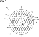
- a fifth wall portion 20 corresponding to the second wall portion 14 may have a polygonal shape in cross section including a plurality of straight inner surfaces 20a connected together so as to be formed into a hoop shape, instead of a round shape. Since the fifth wall portion 20 has the respective inner surfaces 20a also intersecting with the line LN extending from the middle region to the circumferential edge of the first surface 12a at the intersection point P 4 , the fluid disperser 10 can also achieve the above effects accordingly.
- the term "hoop shape" is not intended to be limited to a completely hoop shape.
- the second wall portion 14 may have any shape divided in some parts, but presumed to entirely have a hoop shape so as to achieve the above effects in the same manner.
Landscapes
- Chemical & Material Sciences (AREA)
- Engineering & Computer Science (AREA)
- Organic Chemistry (AREA)
- Chemical Kinetics & Catalysis (AREA)
- Physics & Mathematics (AREA)
- Thermal Sciences (AREA)
- Mechanical Engineering (AREA)
- General Engineering & Computer Science (AREA)
- Physical Or Chemical Processes And Apparatus (AREA)
- Devices And Processes Conducted In The Presence Of Fluids And Solid Particles (AREA)
- Details Of Heat-Exchange And Heat-Transfer (AREA)
- Feeding, Discharge, Calcimining, Fusing, And Gas-Generation Devices (AREA)
Abstract
Description
- The present disclosure relates to a fluid disperser and a fluid dispersing device using the fluid disperser.
- Heat treatment devices such as a reactor and a heat exchanger, and pressure vessels typically use a dispersing plate for dispersing an introduced fluid into a plurality of channels located on the downstream side. Japanese Unexamined Patent Application Publication No.
2007-170271 - Patent Literature 1: Japanese Unexamined Patent Application Publication No.
2007-170271 - When the fluid hits against the perforated plate from the front as disclosed in Japanese Unexamined Patent Application Publication No.
2007-170271 - An object of the present disclosure is to provide a fluid disperser and a fluid dispersing device contributing to an improvement in dispersion performance of a fluid.
- A fluid disperser according to the present disclosure includes: a plate body installed in a channel, having a first wall portion in a middle region of a first surface facing an upstream side, and provided with a plurality of holes allowing a fluid to flow in from an upstream side to a downstream side; and a second wall portion provided on the first surface and having an inner surface intersecting with a line extending from the middle region to a circumferential edge of the first surface.
- A fluid dispersing device according to the present disclosure includes: a tubular-shaped portion having an inner curved surface with a channel having a greater diameter on a downstream side than on an upstream side; an opening portion provided in the tubular-shaped portion and allowing a fluid to flow into the channel; and the fluid disperser described above installed in the channel, wherein the first wall portion of the fluid disperser is opposed to an opening of the opening portion, and the second wall portion of the fluid disperser protrudes toward the inner curved surface.
- The present disclosure can provide a fluid disperser and a fluid dispersing device contributing an improvement in dispersion performance of a fluid.
-
- [
FIG. 1] FIG. 1 is a view showing a configuration of a fluid dispersing device according to an embodiment of the present disclosure. - [
FIG. 2A] FIG. 2A is a perspective view showing a fluid disperser according to the embodiment of the present disclosure, as viewed from the side on which a reaction fluid hits. - [
FIG. 2B] FIG. 2B is a perspective view showing the fluid disperser according to the embodiment of the present disclosure, as viewed from the side on which the reaction fluid is led out. - [
FIG. 3A] FIG. 3A is a plan view showing the fluid disperser according to the embodiment of the present disclosure, as viewed from the side provided with afirst surface 12a. - [
FIG. 3B] FIG. 3B is a plan view showing the fluid disperser according to the embodiment of the present disclosure, as viewed from the side provided with asecond surface 12b. - [
FIG. 4] FIG. 4 is a diagram for explaining dimensional conditions of the fluid disperser according to the embodiment of the present disclosure. - [
FIG. 5] FIG. 5 is a view showing a configuration of a fluid disperser according to another embodiment of the present disclosure. - [
FIG. 6] FIG. 6 is a view showing a configuration of a fluid dispersing device of a comparative example. - Hereinafter, exemplary embodiments of the present disclosure will be described with reference to the accompanying drawings. The following dimensions, materials, and specific numerical values described in the embodiments are shown for illustration purposes, and the present disclosure is not intended to be limited thereto unless otherwise specified. The elements having substantially the same functions and structures are designated by the same reference numerals, and overlapping explanations are not repeated below. The elements described below but not related directly to the present disclosure are not shown in the drawings. In the following explanations of the drawings, a plane parallel to a surface of a plate body provided with a plurality of holes is defined as an X-Y plane, and a direction perpendicular to the X-Y plane in which the holes penetrate is defined as a Z direction.
-
FIG. 1 is a partial perspective view showing a configuration of a fluid dispersing device according to an embodiment of the present disclosure. The fluid dispersing device according to the present disclosure is used for a heat treatment device such as a reactor and a heat exchanger, or a pressure vessel. The fluid dispersing device according to the present disclosure disperses an introduced fluid to a plurality of channels provided on the downstream side. The fluid dispersing device according to the present embodiment is illustrated with a case presumed to be installed in a reactor. As used herein, the term "reactor" refers to a device which uses heat exchange between a reaction fluid and a heat medium, and heats and cools the reaction fluid in a gas or liquid state containing a reaction raw material as a reactant to promote a reaction of the reactant, so as to produce a desirable product. - The
reactor 100 includes aheat exchange unit 110 as a main unit, and afluid dispersing device 120 as a fluid introduction unit for introducing a fluid to theheat exchange unit 110. The fluid introduced to thefluid dispersing device 120 may be either a reaction fluid or a heat medium, and is presumed to be herein a reaction fluid. - The
heat exchange unit 110 produces a product from raw material gas contained in the reaction fluid. Theheat exchange unit 110 includes a plurality of first heat transfer bodies and a plurality of second heat transfer bodies. The first heat transfer bodies and the second heat transfer bodies are each a plate-like member formed of a heat transfer material having high thermal resistance. The first heat transfer bodies and the second heat transfer bodies are alternately stacked on one another so as to entirely compose theheat exchange unit 110 having a cuboidal shape. - The first heat transfer bodies include a plurality of first channels aligned in the Y direction in rows. The first channels are in-pipe channels serving as reaction channels in which the reaction fluid introduced through the
fluid dispersing device 120 flows. Theopenings 130 on the inlet side of the first channels correspond to the openings at the tips of the pipes facing a third space S3 on thefluid dispersing device 120 side. The openings on the outlet side of the first channels (not shown) are provided at different positions in theheat exchange unit 110, and allow the produced product, for example, to be discharged to the outside. - The second heat transfer bodies include a plurality of second channels aligned in the Y direction. The second channels are in-pipe channels serving as heat medium channels in which the heat medium flows through. The openings on the inlet side of the second channels (not shown) are provided to face the
fluid dispersing device 120 on the opposite side in the Z direction, so as to introduce the heat medium through a heat medium introduction unit having a shape similar to a tubular-shaped portion 140 of thefluid dispersing device 120. The openings on the outlet side of the second channels (not shown) are provided at different positions in theheat exchange unit 110, and allow the heat medium having passed through the second channels to be discharged to the outside. - The heat exchange unit 101 has a counter flow-type structure in which the reaction fluid in the first channels and the heat medium in the second channels flow in directions opposite to each other. The first channels cause received heat, supplied from the heat medium flowing through the second channels, to react with the raw material gas so as to produce a product.
- The
fluid dispersing device 120 includes the tubular-shaped portion 140, and afluid disperser 10 according to the embodiment of the present disclosure and aperforated plate 150 installed in the tubular-shaped portion 140. - The tubular-
shaped portion 140 has two openings opposed to each other in the Z direction, and has an internal space serving as a channel for the reaction fluid. One of the openings serves as afirst opening portion 140a from which the reaction fluid is introduced, and the other opening serves as asecond opening portion 140b from which the reaction fluid is led out toward theheat exchange unit 110.FIG. 1 illustrates thesecond opening portion 140b integrated with theheat exchange unit 110. The tubular-shapedportion 140 has a hoop shape in cross section along the X-Y plane perpendicular to an axis which is presumed to be a central axis along the Z direction. A channel diameter, which is an inner diameter of the tubular-shapedportion 140, gradually increases from the upstream side to the downstream side. The channel diameter at thefirst opening portion 140a is smallest, and the channel diameter at thesecond opening portion 140b is greatest. Namely, the tubular-shapedportion 140 has an innercurved surface 140c having a greater channel diameter on the downstream side than on the upstream side. - The
first opening portion 140a is connected to a reaction fluid supply unit provided outside thereactor 100 via a supply pipe (not shown). An inner diameter of thefirst opening portion 140a is thus set to be substantially the same as a pipe diameter of the supply pipe. Thesecond opening portion 140b has an inner diameter sufficient to entirely cover the side surface of theheat exchange unit 110 provided with a plurality ofopenings 130. The tubular-shapedportion 140 is thus provided with a closed inner space facing the side surface of theheat exchange unit 110 on the reaction fluid introduction side. - The tubular-shaped
portion 140 is detachable or openable with respect to theheat exchange unit 110. The detachable or openable tubular-shapedportion 140 allows thefluid disperser 10 and theperforated plate 150 to be installed in the inner space. Theheat exchange unit 110 can be additionally provided with a catalyst body contributing to the reaction inside the respective first channels. The detachable or openable tubular-shapedportion 140 also allows an operator to insert or remove the catalyst body into or from the first channels. -
FIG. 2A is a perspective view showing thefluid disperser 10 as viewed from the side on which the reaction fluid hits.FIG. 2B is a perspective view showing thefluid disperser 10 as viewed from the side on which the reaction fluid is led out. - The
fluid disperser 10 includes a disk-like plate body 12. Theplate body 12 has front and rear main surfaces having a round shape. The surface of theplate body 12 on the side on which the reaction fluid hits, which is the main surface facing the upstream side when installed in the channel of the tubular-shapedportion 140, is herein defined as afirst surface 12a. The surface of theplate body 12 on the side in which the reaction fluid is led out, which is the main surface facing the downstream side when installed in the channel of the tubular-shapedportion 140, is herein defined as asecond surface 12b. Theplate body 12 is provided with a plurality ofholes 12c penetrating thefirst surface 12a and thesecond surface 12b so as to allow the reaction fluid to flow in from the upstream side to the downstream side. Theholes 12c are formed not entirely on the entire main plane surface of theplate body 12, particularly not provided in the middle region of the main plane surface. The middle region of theplate body 12 not provided with theholes 12c is herein defined as afirst wall portion 12d. - The
fluid disperser 10 includes asecond wall portion 14 provided on thefirst surface 12a. Thesecond wall portion 14 according to the present embodiment is a hoop-shaped member provided about the middle region serving as a reference of a center. Thesecond wall portion 14 is prepared independently of theplate body 12, and can be fixed to theplate body 12 by welding or bonding. Alternatively, theplate body 12 and thesecond wall portion 14 may be preliminarily and integrally prepared. The conditions for defining thesecond wall portion 14 are described in detail below. - The
fluid disperser 10 further includes athird wall portion 16 and afourth wall portion 18 provided on thesecond surface 12b. Thethird wall portion 16 and thefourth wall portion 18 according to the present embodiment are each a hoop-shaped member provided about the middle region serving as a reference of a center. An inner diameter of thethird wall portion 16 is greater than an outer diameter of thefourth wall portion 18. Thethird wall portion 16 and thefourth wall portion 18 are both prepared independently of theplate body 12, and can be fixed to theplate body 12 by welding or bonding. Alternatively, theplate body 12 and the third andfourth wall portions third wall portion 16 and thefourth wall portion 18 are described in detail below. -
FIG. 3A is a plan view showing thefluid disperser 10 as viewed from the side provided with thefirst surface 12a.FIG. 3B is a plan view showing thefluid disperser 10 as viewed from the side provided with thesecond surface 12b. - As shown in
FIG. 3A , thesecond wall portion 14 has aninner surface 14a intersecting with a line LN extending from the middle region to the circumferential edge of thefirst surface 12a. The middle region used herein is defined as a centroid P0. The line LN radially extending from the centroid P0 to the circumferential edge needs to hit at any point along thesecond wall portion 14. Since thesecond wall portion 14 according to the present embodiment has a hoop shape in cross section taken along the X-Y plane, the line LN necessarily hits to intersect with theinner surface 14a of thesecond wall portion 14 at the intersection point P1 regardless of which direction the line LN extends from the centroid P0 within the X-Y plane. - As shown in
FIG. 3B , thethird wall portion 16 and thefourth wall portion 18 also preferably meet the conditions similar to the above conditions regarding thesecond wall portion 14. In particular, thethird wall portion 16 has aninner surface 16a intersecting with the line LN extending from the middle region to the circumferential edge of theplate body 12 at the intersection point P2. Similarly, thefourth wall portion 18 has aninner surface 18a intersecting with the line LN extending from the middle region to the circumferential edge of theplate body 12 at the intersection point P3. -
FIG. 4 is a cross-sectional side view for explaining the dimensional conditions for thefluid disperser 10. Theplate body 12 has an outer diameter D and a thickness to. Theholes 12c provided in theplate body 12 have an opening diameter d0. Thesecond wall portion 14 has a thickness t1, an inner diameter d1, and a height L1 from thefirst surface 12a. Thethird wall portion 16 has a thickness t2, an inner diameter d2, and a height L2 from thesecond surface 12b. Thefourth wall portion 18 has a thickness t3, an inner diameter d3, and the same height L2 from thesecond surface 12b as thethird wall portion 16. The thicknesses t1, t2, and t3 of the respective walls are preferably, but not necessarily, smaller than the opening diameter do of theholes 12c so as not to increase the number of theholes 12c blocked by these walls. The respective conditions for thefluid disperser 10 as defined above are described in more detail below together with the operations of thefluid disperser 10 and thefluid dispersing device 120. - The
perforated plate 150 is a fluid dispersing plate provided with a plurality ofholes 150a so as to allow the reaction fluid to flow in from the upstream side to the downstream side. As illustrated inFIG. 1 , theperforated plate 150 is arranged parallel to theplate body 12 of thefluid disperser 10 on the downstream side of thefluid disperser 10 in the channel of the tubular-shapedportion 140. An outer diameter of theperforated plate 150, which varies depending on the position to be located, can be equivalent to the inner diameter of the tubular-shapedportion 140 without being in direct contact with the tubular-shapedportion 140. A thickness of theperforated plate 150 can be equivalent to the thickness to of theplate body 12 of thefluid disperser 10. An opening diameter of theholes 150a provided in theperforated plate 150 can be equivalent to the opening diameter of theholes 12c provided in theplate body 12 of thefluid disperser 10. - The channel of the tubular-shaped
portion 140 is provided with three spaces defined by thefluid disperser 10 and theperforated plate 150. In particular, a first space S1 is defined between thefirst opening portion 140a and thefluid disperser 10, a second space S2 is defined between thefluid disperser 10 and theperforated plate 150, and a third space S3 is defined between theperforated plate 150 and thesecond opening portion 140b. - The operations according to the present embodiment are described below with reference to
FIG. 1. FIG. 1 indicates the reaction fluid R and flowing directions by the solid-white arrows. - The
fluid disperser 10 is preliminarily installed in the channel of the tubular-shapedportion 140 such that thefirst wall portion 12d in the middle region of theplate body 12 is opposed to the opening of thefirst opening portion 140a. The outer diameter D of theplate body 12 is preliminarily set to be equivalent to the inner diameter of the tubular-shapedportion 140 without being in direct contact with the tubular-shapedportion 140. In other words, a gap is actually present between the circumferential edge of theplate body 12 and the inner surface of the tubular-shapedportion 140 adjacent to the circumferential edge. - The reaction fluid R1 supplied from the external reaction fluid supply unit flows through the
first opening portion 140a into the first space S1 in the tubular-shapedportion 140. The flowing reaction fluid R1 hits against thefirst wall portion 12d of thefluid disperser 10. The reaction fluid R2 after hitting flows radially along thefirst surface 12a, since thefirst wall portion 12d is provided with noholes 12c. - According to the present embodiment, the
second wall portion 14 is provided on thefirst surface 12a. When thefluid disperser 10 is installed particularly at a position close to thefirst opening portion 140a, thesecond wall portion 14 protrudes from thefirst surface 12a toward the innercurved surface 140c of the tubular-shapedportion 140. The innercurved surface 140c is present on the extension of theinner surface 14a of thesecond wall portion 14 in the Z direction perpendicular to thefirst surface 12a. The reaction fluid R2 flowing radially along thefirst surface 12a thus hits against theinner surface 14a of thesecond wall portion 14. The reaction fluid R3 hitting against theinner surface 14a changes the flowing direction so as to flow toward the innercurved surface 140c. The reaction fluid hitting against the innercurved surface 140c is divided into two directions. - First, part of the reaction fluid hitting against the inner
curved surface 140c, which is indicated as the reaction fluid R4, is caused to make a flow of recirculation inside thesecond wall portion 14 to return to thefirst wall portion 12d and again flow along thefirst surface 12a toward thesecond wall portion 14. When a pressure inside thesecond wall portion 14 increases, some of the flow of recirculation, which is indicated as the reaction fluid R5, then passes through theholes 12c in theplate body 12 present inside thesecond wall portion 14 to further flow into the second space S2. - Second, the rest of the reaction fluid hitting against the inner
curved surface 140c, which is indicated as the reaction fluid R6, flows toward the circumferential edge of theplate body 12 along the innercurved surface 140c. When a pressure adjacent to the circumferential edge increases, some of the reaction fluid R6, which is indicated as the reaction fluid R7, passes through theholes 12c in theplate body 12 present outside thesecond wall portion 14 to further flow into the second space S2. The rest of the reaction fluid R6, which is indicated as the reaction fluid R8, passes through the gap between the circumferential edge of theplate body 12 and the inner surface of the tubular-shapedportion 140 adjacent to the circumferential edge to further flow into the second space S2. - As described above, the reaction fluid flowing through the
fluid disperser 10 is divided into the reaction fluid such as the reaction fluid R5 dispersed around the middle region of theplate body 12, and the reaction fluid such as the reaction fluid R7 dispersed around the circumferential edge of theplate body 12. Thefluid disperser 10 thus can allow the reaction fluid to flow therethrough so as to be led out of substantially the entire region of thesecond surface 12b while avoiding local dispersion of the reaction fluid to be led out through a particular region, improving the dispersion performance accordingly. - The reaction fluid R5, R7, or R8 flowing into the second space S2 further flows substantially straight toward the
perforated plate 150, and passes through theholes 150a provided in theperforated plate 150. The reaction fluid R9 passing through theholes 150a is regulated by theperforated plate 150 to lead to the substantially uniform flow velocity distribution on the entire surface of theperforated plate 150, so as to keep the balance of distribution of the reaction fluid toward therespective openings 130 provided in theheat exchange unit 110. - A comparative example is illustrated below with a flow of a reaction fluid R in a case of not including the
fluid disperser 10 according to the present embodiment.FIG. 6 is a partial perspective view showing a configuration of afluid dispersing device 220 of the comparative example.FIG. 6 illustrates the configuration corresponding toFIG. 1 , and also indicates the reaction fluid R and flowing directions by the solid-white arrows. - The
fluid dispersing device 220 is used for areactor 200, as in the case of the present embodiment. Thefluid dispersing device 220 differs from thefluid dispersing device 120 according to the present embodiment in including, instead of thefluid disperser 10, a simpleperforated plate 230 provided with a plurality ofholes 230a. Theperforated plate 230 is equivalent in structure to theplate body 12 included in thefluid disperser 10 for the purpose of easy comparison. - The reaction fluid R1 supplied from the external reaction fluid supply unit hits against the surface of the
perforated plate 230 and then flows radially along the surface, which is similar to the case described in the above embodiment. - The
perforated plate 230 does not include thesecond wall portion 14 according to the present embodiment. The reaction fluid R2 thus flows along the surface toward the circumferential edge of theperforated plate 230. The reaction fluid R2 reaching the circumferential edge is then divided into two directions. - First, part of the reaction fluid R2 reaching the circumferential edge, which is indicated as the reaction fluid R3, is caused to make a flow of recirculation to return to the first opening portion140a along the inner
curved surface 140a of the tubular-shapedportion 140, and again flow along the surface of theperforated plate 230 toward the circumferential edge. The flow of recirculation then joins the reaction fluid R2. - Second, the rest of the reaction fluid R2 reaching the circumferential edge, which is indicated as the reaction fluid R4, passes through the
holes 230a present adjacent to the circumferential edge upon an increase in pressure, and also passes through the gap between the circumferential edge and the inner surface of the tubular-shapedportion 140 adjacent to the circumferential edge to further flow into the second space S2. - As described above, most of the reaction fluid flowing through the
perforated plate 230, as illustrated with the reaction fluid R4, is dispersed around the circumferential edge of theperforated plate 230. Namely, the reaction fluid flowing through theperforated plate 230 is led out only of a particular region on the rear surface of theperforated plate 230 corresponding to thesecond surface 12b of theplate body 12. - The reaction fluid R4 flowing into the second space S2 further flows substantially straight toward the
perforated plate 150. This increases the flow velocity more for the reaction fluid R9b having passed through theholes 150a present at the circumferential edge of theperforated plate 150 than for the reaction fluid R9a having passed through theholes 150a present in a wider region including the middle region of theperforated plate 150, regardless of whether the reaction fluid R9 is regulated by theperforated plate 150. The unevenness of the flow velocity distribution is thus caused along the surface of theperforated plate 150, failing to keep the balance of distribution of the reaction fluid toward therespective openings 130 provided in theheat exchange unit 110. - Next, the advantageous effects according to the present embodiment are described below.
- The
fluid disperser 10 includes theplate body 12 which is installed in the channel, has thefirst wall portion 12d in the middle region of thefirst surface 12a facing the upstream side, and is provided with theplural holes 12c allowing the fluid to flow in from the upstream side to the downstream side. Thefluid disperser 10 further includes thesecond wall portion 14 which is provided on thefirst surface 12a and has theinner surface 14a intersecting with the line LN extending from the middle region to the circumferential edge of thefirst surface 12a. - The fluid introduced toward the
first wall portion 12d radially flows along thefirst surface 12a, and then hits against theinner surface 14a of thesecond wall portion 14. Thefluid disperser 10 can divide the flowing fluid into the fluid passing through theholes 12c located inside thesecond wall portion 14 and the fluid passing through the holed 12c located outside thesecond wall portion 14. If theplate body 12 is not provided with thesecond wall portion 14, as described in the comparative example, most of the fluid would be dispersed mainly from the circumferential edge of theplate body 12, which has a problem of failing to keep the balance of distribution of the reaction fluid from the entire surface of theplate body 12. Thefluid disperser 10 according to the present embodiment thus can improve the dispersion performance of the fluid. - The
second wall portion 14 included in thefluid disperser 10 according to the present embodiment has a hoop shape in cross section, which is parallel to thefirst surface 12a, located about the middle region serving as a reference of a center. - One of the effects of the
fluid disperser 10 according to the present embodiment is to enable the fluid flowing along thefirst surface 12a after hitting against thefirst wall portion 12d to further hit against theinner surface 14a due to the hoop shape of thesecond wall portion 14 in cross section. Another effect is to allow the fluid hitting against thefirst wall portion 12d and radially flowing along thefirst surface 12a to hit against theinner surface 14a of thesecond wall portion 14 at substantially the same timing in any radial direction, since the base of thesecond wall portion 14 when installed is set to conform to the middle region of thefirst surface 12a. This enables the fluid dispersed by thefluid disperser 10 to equivalently flow in all radial directions, so as to improve the balance of dispersion of the fluid. Still another effect is to facilitate the manufacture of thesecond wall portion 14 due to the hoop shape in cross section. - The
second wall portion 14 included in thefluid disperser 10 according to the present embodiment has the height L1, which is smaller than the opening diameter do of therespective holes 12c provided in theplate body 12. - The
fluid disperser 10 according to the present embodiment, first, can change the flowing direction of the fluid flowing along thefirst surface 12a after hitting against thefirst wall portion 12d by theinner surface 14a of thesecond wall portion 14. Second, setting the height L1 of thesecond wall portion 14 to be smaller than the opening diameter d0 of theholes 12c can avoid obstructing the flow of the fluid, which is to climb over thesecond wall portion 14 later to flow out of thesecond wall portion 14. The height L1 of thesecond wall portion 14 is preferably set to be greater than (0.4 × the opening diameter d0) and smaller than the opening diameter do in order to achieve these effects more effectively. - The
fluid disperser 10 according to the present embodiment further includes thethird wall portion 16 having theinner surface 16a provided on thesecond surface 12b of theplate body 12 on the opposite side of thefirst surface 12a and intersecting with the line LN extending from the middle region to the circumferential edge of thesecond surface 12b. - The
third wall portion 16 included in thefluid disperser 10 according to the present embodiment can avoid the flow of recirculation of the fluid having passed through theholes 12c to be led out of thesecond surface 12b, so as to regulate the fluid to flow in a designed direction toward the downstream side. - The
third wall portion 16 included in thefluid disperser 10 according to the present embodiment has the height L2 which is greater than the height L1 of thesecond wall portion 14. - The
third wall portion 16 included in thefluid disperser 10 according to the present embodiment enables both the prevention of recirculation of the fluid having passed through theholes 12c to be led out of thesecond surface 12b, and the regulation of flow of the fluid more precisely. The height L2 of thethird wall portion 16 is preferably set to be greater than (3 × the opening diameter d0) of theholes 12c and smaller than (5 × the opening diameter d0) in order to achieve these effects more effectively. The above conditions regarding the heights are also applied to thefourth wall portion 18. WhileFIG. 4 illustrates the case in which thethird wall portion 16 and thefourth wall portion 18 have the same height L2, the respective heights may be different from each other. - The
third wall portion 16 included in thefluid disperser 10 according to the present embodiment has the inner diameter d2, which is the same as or greater than the inner diameter d1 of thesecond wall portion 14. - The
third wall portion 16 included in thefluid disperser 10 according to the present embodiment enables the regulation of the flow of the fluid having passed through theholes 12c particularly inside thesecond wall portion 14, so as to improve the efficiency of regulation of the flow in theentire fluid disperser 10. - The
fluid disperser 10 according to the present embodiment further includes thefourth wall portion 18 having theinner surface 18a provided on thesecond surface 12b and intersecting with the line LN extending from the middle region to the circumferential edge of thesecond surface 12b. The outer diameter of thefourth wall portion 18 is smaller than the inner diameter of each of thesecond wall portion 14 and thethird wall portion 16. - The
fluid disperser 10 according to the present embodiment including the plural wall portions such as thefourth wall portion 18 in addition to thethird wall portion 16 on thesecond surface 12b, can regulate the flow of the fluid passing through theholes 12c with higher accuracy. The outer diameter of thefourth wall portion 18 is preferably set to be smaller than the inner diameter of each of thesecond wall portion 14 and thethird wall portion 16. Some of the reaction fluid R5 flowing into the second space S2 (refer toFIG. 1 ) and further flowing toward the outer circumferential side can be regulated along theinner surface 16a of thethird wall portion 16, and the rest of the reaction fluid R5 flowing toward the inner circumferential side can be regulated along theouter surface 18b of thefourth wall portion 18. The reaction fluid R5 is thus to flow toward theperforated plate 150 approximately straight, so as to facilitate the regulation of the flow by theperforated plate 150 more efficiently. - The
fluid dispersing device 120 according to the present embodiment includes the tubular-shapedportion 140 having the innercurved surface 140c having a greater channel diameter on the downstream side than on the upstream side, theopening portion 140a leading the fluid to flow into the channel, and thefluid disperser 10 installed in the channel. Thefirst wall portion 12d of thefluid disperser 10 is opposed to the opening of theopening portion 140a. Thesecond wall portion 14 of thefluid disperser 10 protrudes toward the innercurved wall 140c. - The
fluid dispersing device 120 according to the present embodiment uses thefluid disperser 10 enabling the improvement in dispersion performance of the fluid, so as to contribute to the equalization of the fluid velocity distribution and the improvement in dispersion balance of the fluid discharged from thefluid dispersing device 120. Thefluid disperser 10 is installed in the channel of the tubular-shapedportion 140 such that thefirst wall portion 12d is opposed to the opening of theopening portion 140a, and thesecond wall portion 14 protrudes toward the innercurved surface 140c, so as to achieve the effects described above more effectively. - The
fluid dispersing device 120 according to the present embodiment includes theperforated plate 150 provided with theplural holes 150a allowing the fluid to flow in from the upstream side to the downstream side. Theperforated plate 150 is installed parallel to theplate body 12 of thefluid disperser 10 on the downstream side of thefluid disperser 10 in the channel of the tubular-shapedportion 140. - The
fluid dispersing device 120 according to the present embodiment including thefluid disperser 10 and further theperforated plate 150 installed on the downstream side of thefluid disperser 10 can achieve the equalization of the fluid velocity distribution and the improvement in dispersion balance of the fluid discharged from thefluid dispersing device 120 more effectively. - The present disclosure has been illustrated with the case in which the
second wall portion 14 has a hoop shape, in particular a round shape in cross section, but is not limited to this case. For example, as shown inFIG. 5 , afifth wall portion 20 corresponding to thesecond wall portion 14 may have a polygonal shape in cross section including a plurality of straightinner surfaces 20a connected together so as to be formed into a hoop shape, instead of a round shape. Since thefifth wall portion 20 has the respectiveinner surfaces 20a also intersecting with the line LN extending from the middle region to the circumferential edge of thefirst surface 12a at the intersection point P4, thefluid disperser 10 can also achieve the above effects accordingly. - While the
second wall portion 14 is illustrated with the case of having a hoop shape in cross section, the term "hoop shape" is not intended to be limited to a completely hoop shape. For example, thesecond wall portion 14 may have any shape divided in some parts, but presumed to entirely have a hoop shape so as to achieve the above effects in the same manner. - It should be understood that the present disclosure includes various embodiments which are not disclosed herein. Therefore, the scope of the present disclosure is defined only by the matters according to the claims reasonably derived from the description above.
Claims (10)
- A fluid disperser comprising:a plate body installed in a channel, having a first wall portion in a middle region of a first surface facing an upstream side, and provided with a plurality of holes allowing a fluid to flow in from an upstream side to a downstream side; anda second wall portion provided on the first surface and having an inner surface intersecting with a line extending from the middle region to a circumferential edge of the first surface.
- The fluid disperser according to claim 1, wherein a shape of the second wall portion in cross section parallel to the first surface is a hoop shape about the middle region of the first surface serving as a reference of a center.
- The fluid disperser according to claim 1 or 2, wherein a height of the second wall portion is smaller than an opening diameter of the respective holes provided in the plate body.
- The fluid disperser according to any one of claims 1 to 3, further comprising a third wall portion provided on a second surface of the plate body on an opposite side of the first surface, and having an inner surface intersecting with a line extending from a middle region to a circumferential edge of the second surface.
- The fluid disperser according to claim 4, wherein a shape of the third wall portion in cross section parallel to the second surface is a hoop shape about the middle region of the second surface serving as a reference of a center.
- The fluid disperser according to claim 4 or 5, wherein a height of the third wall portion is greater than a height of the second wall portion.
- The fluid disperser according to any one of claims 4 to 6, wherein an inner diameter of the third wall portion is equal to or greater than an inner diameter of the second wall portion.
- The fluid disperser according to any one of claims 4 to 7, further comprising a fourth wall portion provided on the second surface, and having an inner surface intersecting with the line extending from the middle region to the circumferential edge of the second surface,
wherein an outer diameter of the fourth wall portion is smaller than an inner diameter of each of the second wall portion and the third wall portion. - A fluid dispersing device comprising:a tubular-shaped portion having an inner curved surface with a channel having a greater diameter on a downstream side than on an upstream side;an opening portion provided in the tubular-shaped portion and allowing a fluid to flow into the channel; andthe fluid disperser according to any one of claims 1 to 8 installed in the channel,wherein the first wall portion of the fluid disperser is opposed to an opening of the opening portion, andthe second wall portion of the fluid disperser protrudes toward the inner curved surface.
- The fluid dispersing device according to claim 9, further comprising a perforated plate provided with a plurality of holes allowing the fluid to flow in from the upstream side to the downstream side, the perforated plate being installed parallel to the plate body of the fluid disperser on the downstream side of the fluid disperser in the channel.
Applications Claiming Priority (2)
| Application Number | Priority Date | Filing Date | Title |
|---|---|---|---|
| JP2017135286A JP6988209B2 (en) | 2017-07-11 | 2017-07-11 | Fluid disperser and fluid disperser |
| PCT/JP2018/025710 WO2019013128A1 (en) | 2017-07-11 | 2018-07-06 | Fluid disperser and fluid dispersing device |
Publications (3)
| Publication Number | Publication Date |
|---|---|
| EP3653289A1 true EP3653289A1 (en) | 2020-05-20 |
| EP3653289A4 EP3653289A4 (en) | 2021-03-24 |
| EP3653289B1 EP3653289B1 (en) | 2025-12-10 |
Family
ID=65001647
Family Applications (1)
| Application Number | Title | Priority Date | Filing Date |
|---|---|---|---|
| EP18831550.1A Active EP3653289B1 (en) | 2017-07-11 | 2018-07-06 | Fluid disperser and fluid dispersing device |
Country Status (6)
| Country | Link |
|---|---|
| US (1) | US11650019B2 (en) |
| EP (1) | EP3653289B1 (en) |
| JP (1) | JP6988209B2 (en) |
| CN (1) | CN110869116B (en) |
| CA (1) | CA3069290C (en) |
| WO (1) | WO2019013128A1 (en) |
Families Citing this family (1)
| Publication number | Priority date | Publication date | Assignee | Title |
|---|---|---|---|---|
| USD1037778S1 (en) * | 2022-07-19 | 2024-08-06 | Applied Materials, Inc. | Gas distribution plate |
Family Cites Families (35)
| Publication number | Priority date | Publication date | Assignee | Title |
|---|---|---|---|---|
| US3623505A (en) * | 1969-08-20 | 1971-11-30 | Westinghouse Electric Corp | Flow distribution device |
| US3630276A (en) * | 1970-02-10 | 1971-12-28 | Nasa | Shell-side liquid metal boiler |
| JPS51137763U (en) | 1975-04-30 | 1976-11-06 | ||
| US4576222A (en) * | 1982-08-31 | 1986-03-18 | Westinghouse Electric Corp. | Fluid distributor for heat exchanger inlet nozzle |
| DE3427298C2 (en) * | 1984-07-24 | 1987-03-12 | GEA Wiegand GmbH, 7505 Ettlingen | Device for distributing a liquid in a distribution chamber onto a perforated floor |
| JP3252165B2 (en) * | 1991-04-18 | 2002-01-28 | 川崎重工業株式会社 | Exhaust gas treatment equipment |
| US5107923A (en) * | 1991-06-10 | 1992-04-28 | United Technologies Corporation | Flow distribution device |
| US5261485A (en) * | 1991-08-21 | 1993-11-16 | Hpd, Incorporated | Slurry distributor |
| US5415223A (en) * | 1993-08-02 | 1995-05-16 | Calsonic International, Inc. | Evaporator with an interchangeable baffling system |
| JP3497029B2 (en) | 1994-12-28 | 2004-02-16 | 三井化学株式会社 | Gas dispersion plate for gas phase polymerization equipment |
| JP2705721B2 (en) * | 1995-06-09 | 1998-01-28 | 川崎重工業株式会社 | Liquefied gas evaporator |
| US5752538A (en) * | 1995-12-13 | 1998-05-19 | Praxair Technology, Inc. | Liquid distributor for packed columns |
| CN1186873A (en) * | 1996-11-26 | 1998-07-08 | 西门子公司 | Distribution plate for reaction chamber with multiple gas inlets and separate mass flow control loops |
| FR2766914B1 (en) * | 1997-07-29 | 1999-10-29 | D Applic Thermiques Comp Ind | DISTRIBUTOR FOR FITTING INTRATUBULAR HEAT EXCHANGERS OF DIPHASIC-TYPE REFRIGERATION FLUID COOLING PLANTS |
| US6183702B1 (en) | 1998-12-21 | 2001-02-06 | Chevron U.S.A. Inc. | Fluid distributor assembly for a multi-bed, downflow catalytic reactor |
| JP3476705B2 (en) * | 1999-03-31 | 2003-12-10 | アマノ株式会社 | Push airflow generator |
| US6382313B2 (en) * | 2000-02-25 | 2002-05-07 | Nippon Shokubai Co., Ltd. | Heat exchanger for easily polymerizing substance-containing gas provided with gas distributing plate |
| US6537419B1 (en) | 2000-04-26 | 2003-03-25 | David W. Kinnard | Gas distribution plate assembly for providing laminar gas flow across the surface of a substrate |
| JP2002095963A (en) * | 2000-09-25 | 2002-04-02 | Hitachi Zosen Corp | Inlet gas dispersion plate for reactor |
| CN2463043Y (en) * | 2001-01-03 | 2001-12-05 | 太原理工大学 | Gas distributing board |
| FR2824280B1 (en) * | 2001-05-04 | 2003-09-05 | Total Raffinage Distribution | DEVICE FOR THE HOMOGENEOUS DISPENSING OF A FLUID IN A SPEAKER AND USES THEREOF |
| JP4792268B2 (en) | 2005-09-27 | 2011-10-12 | 富士フイルム株式会社 | Fluid device |
| JP4798655B2 (en) * | 2005-12-21 | 2011-10-19 | 臼井国際産業株式会社 | Multi-tube heat exchanger for exhaust gas cooling system |
| EP1962998A1 (en) * | 2005-12-23 | 2008-09-03 | Siemens VAI Metals Technologies GmbH & Co | Distributor bottom |
| US20080078746A1 (en) * | 2006-08-15 | 2008-04-03 | Noriiki Masuda | Substrate processing system, gas supply unit, method of substrate processing, computer program, and storage medium |
| ITMI20071751A1 (en) * | 2007-09-12 | 2009-03-13 | Polidoro S P A | PREMIXED BURNER |
| US8276653B2 (en) * | 2008-03-28 | 2012-10-02 | Saudi Arabian Oil Company | Raised overlapped impingement plate |
| ITMI20100249U1 (en) * | 2010-07-16 | 2012-01-17 | Alfa Laval Corp Ab | HEAT EXCHANGE DEVICE WITH REFRIGERANT FLUID DISTRIBUTION SYSTEM |
| KR101210127B1 (en) * | 2010-07-16 | 2012-12-07 | 삼성에스디아이 주식회사 | Combustor for reformer |
| JP2013154310A (en) * | 2012-01-31 | 2013-08-15 | Ihi Corp | Multitubular reactor |
| CN203683108U (en) * | 2012-12-18 | 2014-07-02 | 英威达科技公司 | Converter used for producing hydrogen cyanide |
| CN203899577U (en) * | 2014-04-30 | 2014-10-29 | 中国石油化工股份有限公司 | Fluid distribution equipment and tower |
| JP2016199790A (en) * | 2015-04-10 | 2016-12-01 | 古河機械金属株式会社 | Film forming apparatus, cleaning apparatus, and holding method |
| CN106606998B (en) * | 2015-10-23 | 2020-03-24 | 中国石油化工股份有限公司 | Upflow Distributors and Upflow Reactors |
| CN205860304U (en) * | 2016-07-21 | 2017-01-04 | 广州高唐科技发展有限公司 | A kind of current stabilization water-locator in novel cold stocking system |
-
2017
- 2017-07-11 JP JP2017135286A patent/JP6988209B2/en active Active
-
2018
- 2018-07-06 CN CN201880045520.0A patent/CN110869116B/en active Active
- 2018-07-06 CA CA3069290A patent/CA3069290C/en active Active
- 2018-07-06 EP EP18831550.1A patent/EP3653289B1/en active Active
- 2018-07-06 WO PCT/JP2018/025710 patent/WO2019013128A1/en not_active Ceased
-
2020
- 2020-01-08 US US16/736,869 patent/US11650019B2/en active Active
Also Published As
| Publication number | Publication date |
|---|---|
| JP6988209B2 (en) | 2022-01-05 |
| JP2019013912A (en) | 2019-01-31 |
| US11650019B2 (en) | 2023-05-16 |
| CA3069290A1 (en) | 2019-01-17 |
| CN110869116B (en) | 2022-02-25 |
| US20200141665A1 (en) | 2020-05-07 |
| EP3653289A4 (en) | 2021-03-24 |
| EP3653289B1 (en) | 2025-12-10 |
| WO2019013128A1 (en) | 2019-01-17 |
| CA3069290C (en) | 2022-05-31 |
| CN110869116A (en) | 2020-03-06 |
Similar Documents
| Publication | Publication Date | Title |
|---|---|---|
| CN101818690B (en) | Gas turbine combustion system cooling arrangement | |
| CN102534563B (en) | Inclined entering gas spray header applied to metal organic chemical vapor deposition reactor | |
| KR102465613B1 (en) | Chamber intake structure and reaction chamber | |
| US9890672B2 (en) | Combustion gas cooling apparatus, denitration apparatus having the combustion gas cooling apparatus, and combustion gas cooling method | |
| EP1489624A2 (en) | Nuclear reactor internal structure | |
| JP2010531426A (en) | Vibration Mitigation Method for Plate Heat Exchanger Port Insert and Heat Exchanger | |
| EP3470183B1 (en) | Rotational flow-forming body and sucking device | |
| ITMI20100249U1 (en) | HEAT EXCHANGE DEVICE WITH REFRIGERANT FLUID DISTRIBUTION SYSTEM | |
| EP3653289B1 (en) | Fluid disperser and fluid dispersing device | |
| US9644511B2 (en) | Combustion gas cooling apparatus, denitration apparatus including the combustion gas cooling apparatus, and combustion gas cooling method | |
| JP2020502471A (en) | Plate heat converter | |
| KR20080001651A (en) | Shower head for gas supply | |
| US20090025918A1 (en) | Flow moderator | |
| JP2012163291A (en) | Distributor | |
| JP6957857B2 (en) | Fluid dispersion device and heat treatment device | |
| EP3527858B1 (en) | Pressure vessel | |
| KR20090051469A (en) | Dissipation nozzle for chemical vapor deposition | |
| CN113739201B (en) | Hood with drainage device | |
| JP7596840B2 (en) | Stack Manifold | |
| CN201959780U (en) | Quenching mixer | |
| CN210385477U (en) | A parallel flow flue gas denitrification reactor | |
| EP3037766B1 (en) | Heat exchanger | |
| JP2013221408A (en) | Egr gas cooling device | |
| JP2025035266A (en) | Heat exchanger | |
| TWM608798U (en) | Mixed baffle and fluid mixing device comprising the same |
Legal Events
| Date | Code | Title | Description |
|---|---|---|---|
| STAA | Information on the status of an ep patent application or granted ep patent |
Free format text: STATUS: THE INTERNATIONAL PUBLICATION HAS BEEN MADE |
|
| PUAI | Public reference made under article 153(3) epc to a published international application that has entered the european phase |
Free format text: ORIGINAL CODE: 0009012 |
|
| STAA | Information on the status of an ep patent application or granted ep patent |
Free format text: STATUS: REQUEST FOR EXAMINATION WAS MADE |
|
| 17P | Request for examination filed |
Effective date: 20200204 |
|
| AK | Designated contracting states |
Kind code of ref document: A1 Designated state(s): AL AT BE BG CH CY CZ DE DK EE ES FI FR GB GR HR HU IE IS IT LI LT LU LV MC MK MT NL NO PL PT RO RS SE SI SK SM TR |
|
| AX | Request for extension of the european patent |
Extension state: BA ME |
|
| DAV | Request for validation of the european patent (deleted) | ||
| DAX | Request for extension of the european patent (deleted) | ||
| A4 | Supplementary search report drawn up and despatched |
Effective date: 20210222 |
|
| RIC1 | Information provided on ipc code assigned before grant |
Ipc: B01J 4/00 20060101AFI20210216BHEP Ipc: F28F 9/22 20060101ALI20210216BHEP |
|
| STAA | Information on the status of an ep patent application or granted ep patent |
Free format text: STATUS: EXAMINATION IS IN PROGRESS |
|
| 17Q | First examination report despatched |
Effective date: 20220613 |
|
| GRAP | Despatch of communication of intention to grant a patent |
Free format text: ORIGINAL CODE: EPIDOSNIGR1 |
|
| STAA | Information on the status of an ep patent application or granted ep patent |
Free format text: STATUS: GRANT OF PATENT IS INTENDED |
|
| INTG | Intention to grant announced |
Effective date: 20250805 |
|
| RIN1 | Information on inventor provided before grant (corrected) |
Inventor name: TSUNODA, DAISUKE Inventor name: SAKAKURA, SHIGEKI Inventor name: HONMA, NOBUYUKI Inventor name: TSURUGAYA, KOHEI |
|
| GRAS | Grant fee paid |
Free format text: ORIGINAL CODE: EPIDOSNIGR3 |
|
| GRAA | (expected) grant |
Free format text: ORIGINAL CODE: 0009210 |
|
| STAA | Information on the status of an ep patent application or granted ep patent |
Free format text: STATUS: THE PATENT HAS BEEN GRANTED |
|
| AK | Designated contracting states |
Kind code of ref document: B1 Designated state(s): AL AT BE BG CH CY CZ DE DK EE ES FI FR GB GR HR HU IE IS IT LI LT LU LV MC MK MT NL NO PL PT RO RS SE SI SK SM TR |
|
| REG | Reference to a national code |
Ref country code: CH Ref legal event code: F10 Free format text: ST27 STATUS EVENT CODE: U-0-0-F10-F00 (AS PROVIDED BY THE NATIONAL OFFICE) Effective date: 20251210 Ref country code: GB Ref legal event code: FG4D |
|
| REG | Reference to a national code |
Ref country code: DE Ref legal event code: R096 Ref document number: 602018087841 Country of ref document: DE |
|
| REG | Reference to a national code |
Ref country code: IE Ref legal event code: FG4D |
|
| PG25 | Lapsed in a contracting state [announced via postgrant information from national office to epo] |
Ref country code: ES Free format text: LAPSE BECAUSE OF FAILURE TO SUBMIT A TRANSLATION OF THE DESCRIPTION OR TO PAY THE FEE WITHIN THE PRESCRIBED TIME-LIMIT Effective date: 20251210 |
|
| REG | Reference to a national code |
Ref country code: LT Ref legal event code: MG9D |
|
| PG25 | Lapsed in a contracting state [announced via postgrant information from national office to epo] |
Ref country code: NO Free format text: LAPSE BECAUSE OF FAILURE TO SUBMIT A TRANSLATION OF THE DESCRIPTION OR TO PAY THE FEE WITHIN THE PRESCRIBED TIME-LIMIT Effective date: 20260310 |
|
| PG25 | Lapsed in a contracting state [announced via postgrant information from national office to epo] |
Ref country code: HR Free format text: LAPSE BECAUSE OF FAILURE TO SUBMIT A TRANSLATION OF THE DESCRIPTION OR TO PAY THE FEE WITHIN THE PRESCRIBED TIME-LIMIT Effective date: 20251210 Ref country code: FI Free format text: LAPSE BECAUSE OF FAILURE TO SUBMIT A TRANSLATION OF THE DESCRIPTION OR TO PAY THE FEE WITHIN THE PRESCRIBED TIME-LIMIT Effective date: 20251210 |
|
| REG | Reference to a national code |
Ref country code: NL Ref legal event code: MP Effective date: 20251210 |
|
| PG25 | Lapsed in a contracting state [announced via postgrant information from national office to epo] |
Ref country code: RS Free format text: LAPSE BECAUSE OF FAILURE TO SUBMIT A TRANSLATION OF THE DESCRIPTION OR TO PAY THE FEE WITHIN THE PRESCRIBED TIME-LIMIT Effective date: 20260310 |
|
| PG25 | Lapsed in a contracting state [announced via postgrant information from national office to epo] |
Ref country code: LV Free format text: LAPSE BECAUSE OF FAILURE TO SUBMIT A TRANSLATION OF THE DESCRIPTION OR TO PAY THE FEE WITHIN THE PRESCRIBED TIME-LIMIT Effective date: 20251210 |
|
| PG25 | Lapsed in a contracting state [announced via postgrant information from national office to epo] |
Ref country code: BG Free format text: LAPSE BECAUSE OF FAILURE TO SUBMIT A TRANSLATION OF THE DESCRIPTION OR TO PAY THE FEE WITHIN THE PRESCRIBED TIME-LIMIT Effective date: 20251210 |
|
| REG | Reference to a national code |
Ref country code: AT Ref legal event code: MK05 Ref document number: 1865655 Country of ref document: AT Kind code of ref document: T Effective date: 20251210 |
|
| PG25 | Lapsed in a contracting state [announced via postgrant information from national office to epo] |
Ref country code: NL Free format text: LAPSE BECAUSE OF FAILURE TO SUBMIT A TRANSLATION OF THE DESCRIPTION OR TO PAY THE FEE WITHIN THE PRESCRIBED TIME-LIMIT Effective date: 20251210 |
|
| PG25 | Lapsed in a contracting state [announced via postgrant information from national office to epo] |
Ref country code: LT Free format text: LAPSE BECAUSE OF FAILURE TO SUBMIT A TRANSLATION OF THE DESCRIPTION OR TO PAY THE FEE WITHIN THE PRESCRIBED TIME-LIMIT Effective date: 20251210 |
|
| PG25 | Lapsed in a contracting state [announced via postgrant information from national office to epo] |
Ref country code: SM Free format text: LAPSE BECAUSE OF FAILURE TO SUBMIT A TRANSLATION OF THE DESCRIPTION OR TO PAY THE FEE WITHIN THE PRESCRIBED TIME-LIMIT Effective date: 20251210 |
|
| PG25 | Lapsed in a contracting state [announced via postgrant information from national office to epo] |
Ref country code: PL Free format text: LAPSE BECAUSE OF FAILURE TO SUBMIT A TRANSLATION OF THE DESCRIPTION OR TO PAY THE FEE WITHIN THE PRESCRIBED TIME-LIMIT Effective date: 20251210 |
|
| PGFP | Annual fee paid to national office [announced via postgrant information from national office to epo] |
Ref country code: GB Payment date: 20260622 Year of fee payment: 9 |
|
| PG25 | Lapsed in a contracting state [announced via postgrant information from national office to epo] |
Ref country code: IT Free format text: LAPSE BECAUSE OF FAILURE TO SUBMIT A TRANSLATION OF THE DESCRIPTION OR TO PAY THE FEE WITHIN THE PRESCRIBED TIME-LIMIT Effective date: 20251210 |
|
| PG25 | Lapsed in a contracting state [announced via postgrant information from national office to epo] |
Ref country code: AT Free format text: LAPSE BECAUSE OF FAILURE TO SUBMIT A TRANSLATION OF THE DESCRIPTION OR TO PAY THE FEE WITHIN THE PRESCRIBED TIME-LIMIT Effective date: 20251210 |
|
| PG25 | Lapsed in a contracting state [announced via postgrant information from national office to epo] |
Ref country code: EE Free format text: LAPSE BECAUSE OF FAILURE TO SUBMIT A TRANSLATION OF THE DESCRIPTION OR TO PAY THE FEE WITHIN THE PRESCRIBED TIME-LIMIT Effective date: 20251210 |
|
| PG25 | Lapsed in a contracting state [announced via postgrant information from national office to epo] |
Ref country code: IS Free format text: LAPSE BECAUSE OF FAILURE TO SUBMIT A TRANSLATION OF THE DESCRIPTION OR TO PAY THE FEE WITHIN THE PRESCRIBED TIME-LIMIT Effective date: 20260410 Ref country code: PT Free format text: LAPSE BECAUSE OF FAILURE TO SUBMIT A TRANSLATION OF THE DESCRIPTION OR TO PAY THE FEE WITHIN THE PRESCRIBED TIME-LIMIT Effective date: 20260410 |
|
| PG25 | Lapsed in a contracting state [announced via postgrant information from national office to epo] |
Ref country code: CZ Free format text: LAPSE BECAUSE OF FAILURE TO SUBMIT A TRANSLATION OF THE DESCRIPTION OR TO PAY THE FEE WITHIN THE PRESCRIBED TIME-LIMIT Effective date: 20251210 |
|
| PG25 | Lapsed in a contracting state [announced via postgrant information from national office to epo] |
Ref country code: SK Free format text: LAPSE BECAUSE OF FAILURE TO SUBMIT A TRANSLATION OF THE DESCRIPTION OR TO PAY THE FEE WITHIN THE PRESCRIBED TIME-LIMIT Effective date: 20251210 |
|
| PG25 | Lapsed in a contracting state [announced via postgrant information from national office to epo] |
Ref country code: SE Free format text: LAPSE BECAUSE OF FAILURE TO SUBMIT A TRANSLATION OF THE DESCRIPTION OR TO PAY THE FEE WITHIN THE PRESCRIBED TIME-LIMIT Effective date: 20251210 |