EP3653123A1 - Apparatus for controlling operation of continuous blood glucose tester - Google Patents
Apparatus for controlling operation of continuous blood glucose tester Download PDFInfo
- Publication number
- EP3653123A1 EP3653123A1 EP19845690.7A EP19845690A EP3653123A1 EP 3653123 A1 EP3653123 A1 EP 3653123A1 EP 19845690 A EP19845690 A EP 19845690A EP 3653123 A1 EP3653123 A1 EP 3653123A1
- Authority
- EP
- European Patent Office
- Prior art keywords
- user terminal
- communication module
- monitoring system
- bluetooth communication
- glucose monitoring
- Prior art date
- Legal status (The legal status is an assumption and is not a legal conclusion. Google has not performed a legal analysis and makes no representation as to the accuracy of the status listed.)
- Granted
Links
Images


Classifications
-
- A—HUMAN NECESSITIES
- A61—MEDICAL OR VETERINARY SCIENCE; HYGIENE
- A61B—DIAGNOSIS; SURGERY; IDENTIFICATION
- A61B5/00—Measuring for diagnostic purposes; Identification of persons
- A61B5/15—Devices for taking samples of blood
- A61B5/150007—Details
- A61B5/150847—Communication to or from blood sampling device
- A61B5/15087—Communication to or from blood sampling device short range, e.g. between console and disposable
-
- A—HUMAN NECESSITIES
- A61—MEDICAL OR VETERINARY SCIENCE; HYGIENE
- A61B—DIAGNOSIS; SURGERY; IDENTIFICATION
- A61B5/00—Measuring for diagnostic purposes; Identification of persons
- A61B5/0002—Remote monitoring of patients using telemetry, e.g. transmission of vital signals via a communication network
-
- A—HUMAN NECESSITIES
- A61—MEDICAL OR VETERINARY SCIENCE; HYGIENE
- A61B—DIAGNOSIS; SURGERY; IDENTIFICATION
- A61B5/00—Measuring for diagnostic purposes; Identification of persons
- A61B5/145—Measuring characteristics of blood in vivo, e.g. gas concentration or pH-value ; Measuring characteristics of body fluids or tissues, e.g. interstitial fluid or cerebral tissue
- A61B5/14532—Measuring characteristics of blood in vivo, e.g. gas concentration or pH-value ; Measuring characteristics of body fluids or tissues, e.g. interstitial fluid or cerebral tissue for measuring glucose, e.g. by tissue impedance measurement
-
- A—HUMAN NECESSITIES
- A61—MEDICAL OR VETERINARY SCIENCE; HYGIENE
- A61B—DIAGNOSIS; SURGERY; IDENTIFICATION
- A61B5/00—Measuring for diagnostic purposes; Identification of persons
- A61B5/0002—Remote monitoring of patients using telemetry, e.g. transmission of vital signals via a communication network
- A61B5/0015—Remote monitoring of patients using telemetry, e.g. transmission of vital signals via a communication network characterised by features of the telemetry system
- A61B5/002—Monitoring the patient using a local or closed circuit, e.g. in a room or building
-
- A—HUMAN NECESSITIES
- A61—MEDICAL OR VETERINARY SCIENCE; HYGIENE
- A61B—DIAGNOSIS; SURGERY; IDENTIFICATION
- A61B5/00—Measuring for diagnostic purposes; Identification of persons
- A61B5/15—Devices for taking samples of blood
- A61B5/150007—Details
- A61B5/150946—Means for varying, regulating, indicating or limiting the speed or time of blood collection
-
- A—HUMAN NECESSITIES
- A61—MEDICAL OR VETERINARY SCIENCE; HYGIENE
- A61B—DIAGNOSIS; SURGERY; IDENTIFICATION
- A61B2560/00—Constructional details of operational features of apparatus; Accessories for medical measuring apparatus
- A61B2560/02—Operational features
- A61B2560/0204—Operational features of power management
- A61B2560/0214—Operational features of power management of power generation or supply
Definitions
- the present disclosure relates to an apparatus for controlling operations of a continuous glucose monitoring system. More specifically, in the apparatus for controlling operations of the continuous glucose monitoring system, when a continuous glucose monitoring system is located within a certain distance of a user terminal, power of a battery can be supplied to the continuous glucose monitoring system through a power switch switched on in response to an enable signal generated by a near field communication module, thereby starting operations of the continuous glucose monitoring system without user intervention.
- the near field communication module can provide connection information to the user terminal, thereby automatically performing a pairing connection with the user terminal using the near field communication module and a bluetooth communication module.
- an enable signal generated by the bluetooth communication module can be provided to the power switch, thereby maintaining the pairing connection with the user terminal, even when the user terminal is outside of a range for near field communication.
- Diabetes is a chronic disease common in modern people. In the Republic of Korea, two million or more people, about 5% of the total population, suffer from diabetes.
- Diabetes is caused by the pancreas producing an entirely, or relatively, insufficient amount of insulin due to a variety of reasons, such as obesity, stress, and bad eating habits, and due to congenital or hereditary reasons, so that glucose levels are absolutely high in blood, instead of being balanced in blood.
- Blood contains a certain concentration of glucose, from which tissue cells produce energy.
- Diabetes has subtle or no subjective symptoms in the early stages of the disease. With the progression of the disease, however, the classic symptoms of diabetes, such as polydipsia, polyphagia, polyuria, weight loss, fatigue, itchy skin, and slow healing of cuts of the hands and feet, appear. Prolonged diabetes may cause complications, such as blurred vision, high blood pressure, nephropathy, palsy, periodontal diseases, muscle spasms, neuralgia, and gangrene.
- the glucose monitoring device uses a method in which a user draws blood from a finger tip and performs a blood glucose measurement once and a method in which the glucose monitoring system is attached to a user's abdomen and arm and blood glucose measurement is continuously performed.
- CGMSs continuous glucose monitoring systems
- Invasive glucose monitoring systems measure blood glucose through a method in which a diabetic patient collects blood by stabbing a pain-sensitive finger tip with a needle to check blood glucose thereof, which may causes pain and repulsion when blood is collected.
- CGMSs that continuously measure blood glucose after a needle-shaped sensor is inserted into a part of the abdomen, the arm, or the like which is relatively less sensitive to pain.
- the CGMS includes a sensor module attached to the skin of the body to extract a body fluid and measure blood glucose and a transmitter configured to transmit a blood glucose level measured by the sensor module to a user terminal.
- the user terminal is provided with a dedicated application program for managing blood glucose information received from the CGMS. A user may check the measured blood glucose information through the dedicated application program of the user terminal.
- a process for establishing communication channel between the CGMS and the user terminal should be primarily performed.
- the user terminal and the CGMS are paired and connected using Bluetooth communication and then communicate with each other.
- the CGMS has the expiration date about two weeks.
- a user In order to pair and connect the CGMS to the user terminal, a user should directly input pairing connection information to the user terminal every time.
- it may be difficult for the user to accurately measure blood glucose information or the user may not be able to measure blood glucose information during a set period due to limited battery power.
- Various aspects of the present disclosure provide an apparatus for controlling operations of a continuous glucose monitoring system.
- a continuous glucose monitoring system When a continuous glucose monitoring system is located within a certain distance of a user terminal, power of a battery can be supplied to the continuous glucose monitoring system through a power switch switched on in response to an enable signal generated by a near field communication module, thereby starting operation of the continuous glucose monitoring system.
- an apparatus for controlling operations of a continuous glucose monitoring system the apparatus being able to maintain a pairing communication with a user terminal by providing an enable signal generated by a bluetooth communication module to a power switch when the pairing connection with the user terminal is completed.
- an apparatus for controlling operations of a continuous glucose monitoring system may include: a near field wireless communication (NFC) module generating a first enable signal when power is supplied from a user terminal; a Bluetooth communication module; and a power switch switched on when the first enable signal is received from the NFC module and supplying power from a battery to the Bluetooth communication module, wherein the Bluetooth communication module transmits an advertising message to the user terminal when the power is supplied from the battery through the power switch.
- NFC near field wireless communication
- the Bluetooth communication module may be activated in response to a connection signal provided through the NFC module and may transmit the advertising message to the user terminal.
- connection signal may be received from the user terminal through the NFC module.
- the NFC module may transmit connection information to the user terminal.
- the NFC module may transmit the connection information provided from the Bluetooth communication module to the user terminal.
- the Bluetooth communication module may maintain communication with the user terminal.
- the Bluetooth communication module may generate a second enable signal and may provide the generated second enable signal to the power switch.
- the power switch may be switched on to supply the power of the battery to the Bluetooth communication module.
- the apparatus for controlling operations of a continuous glucose monitoring system has the following effects.
- the apparatus for controlling operations of a continuous glucose monitoring system when a continuous glucose monitoring system is located within a certain distance from a user terminal, power of the battery can be supplied to the continuous glucose monitoring system through the power switch switched on in response to an enable signal generated by the near field communication module, thereby starting operations of the continuous glucose monitoring system without separate user intervention.
- the near field communication module provides connection information to a user terminal, a pairing connection with the user terminal is automatically performed using the near field communication module and the Bluetooth communication module.
- an enable signal generated by the Bluetooth communication module can be provided to the power switch, thereby maintaining the pairing connection with the user terminal even when the user terminal is out of a distance for short range communication.
- a pairing connection can be performed by transmitting connection information to the user terminal. Accordingly, information of the continuous glucose monitoring system can be transmitted only to a limited user terminal, thereby safely protecting user's personal information.
- FIG. 1 is a diagram illustrating a continuous glucose monitoring system.
- a continuous glucose monitoring system 100 is attached to a skin of a user 1 to periodically extract a body fluid of the user 1 and continuously measure bioinformation of the user 1, for example, a blood glucose level using the extracted body fluid.
- the continuous glucose monitoring system 100 and a user terminal 10 are connected to each other through short range communication, such as bluetooth communication or near field communication (NFC), to transmit and receive data through the short range communication. That is, when the continuous glucose monitoring system 100 and the user terminal 10 are located within a range of the short range communication, the continuous glucose monitoring system 100 transmits measured bioinformation of the user 1 to the user terminal 10.
- short range communication such as bluetooth communication or near field communication (NFC)
- NFC near field communication
- an NFC module (not shown) provided in the continuous glucose monitoring system 100 starts to be operated by receiving power from the user terminal 10.
- the operated NFC module starts to operate a bluetooth communication module (not shown) provided in the continuous glucose monitoring system 100.
- the continuous glucose monitoring system 100 automatically performs a communication connection procedure using the NFC module and the bluetooth communication module to be connected to and communicate with the user terminal 10.
- the continuous glucose monitoring system 100 periodically transmits measured blood glucose information of the user to the user terminal 10.
- the user terminal 10 is a device capable of storing or outputting the blood glucose information of the user 1 received from the continuous glucose monitoring system 100 such that the blood glucose information may be checked and output to the user.
- a dedicated application program for managing blood glucose information may be executed in the user terminal 10.
- a smartphone, a notebook, a personal digital assistant (PDA), a blood glucose management dedicated terminal, or the like may be used.
- the user terminal 10 and a management server 50 are connected to each other via a network 30.
- the user terminal 10 transmits the blood glucose information of the user 1, received from the continuous glucose monitoring system 100, to the management server 50 or transmits sensor use information of the continuous glucose monitoring system 100 to the management server 50.
- the user terminal 10 identifies a user on the basis of inputted user information and registers the received blood glucose information by mapping the received blood glucose information to the identified user.
- the user terminal 10 transmits the registered blood glucose information, mapped to the user, or transmits the sensor use information to the management server 50 together with the user information.
- FIG. 2 is a functional block diagram illustrating an apparatus for controlling operations of a continuous glucose monitoring system according to the present disclosure.
- the NFC module 110 of a continuous glucose monitoring system receives operating power from the user terminal.
- the NFC communication module 110 receiving the operation power generates a first enable signal EN1 and provides the first enable signal EN1 to a power switch 130.
- the NFC module 110 does not generate an enable signal. Only when the operating power is received from the user terminal, does the NFC module 110 generate the first enable signal EN1.
- the power switch 130 controls connection between a battery 150 and a bluetooth communication module 170 in response to a signal input to an enable terminal (not shown).
- an enable terminal not shown.
- the power switch 130 maintains a switched off state.
- the power switch 130 is switched on to connect the battery 150 and the bluetooth communication module 170 to each other.
- the battery 150 and the bluetooth communication module 170 are connected to each other through the power switch 130, power is supplied from the battery 150 to the bluetooth communication module 170.
- the bluetooth communication module 170 When the power is supplied from the battery 150 to the bluetooth communication module 170, the bluetooth communication module 170 starts to be operated.
- the bluetooth communication module 170 first transmits an advertising message including an identifier of the continuous glucose monitoring system to the user terminal. After the bluetooth communication module 170 transmits the advertising message, the bluetooth communication module 170 controls the NFC module 110 to transmit connection information, for example, a pin code necessary for pairing and connecting the user terminal and the continuous glucose monitoring system to the user terminal.
- the bluetooth communication module 170 receives a connection complete message from the user terminal.
- the bluetooth communication module 170 generates a second enable signal and provides the generated second enable signal to an enable terminal of the power switch 130.
- the NFC module 110 of the continuous glucose monitoring system When the NFC module 110 of the continuous glucose monitoring system does not receive power from the user terminal, due to the distance between the user terminal and the continuous glucose monitoring system being greater than the first distance and, the NFC module 110 stops generating the first enable signal EN1.
- the power switch 130 receives at least one of the first enable signal EN1 and the second enable signal EN2 through the enable terminal, the power switch 130 is switched on to connect the battery 150 and the bluetooth communication module 170 to each other.
- the bluetooth communication module 170 may generate the second enable signal EN2 and may provide the second enable signal EN2 to an enable terminal of the NFC module 110.
- the power of the battery 150 may be continuously supplied to the bluetooth communication module 170.
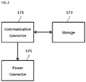
- FIG. 3 is a functional block diagram illustrating an example of the bluetooth communication module 170 according to the present disclosure.
- a communication connector 171 when a connection signal is received from the user terminal through the NFC module, a communication connector 171 generates an advertising message and transmits the advertising message to the user terminal.
- the communication connector 171 generates the advertising message by providing an identifier of the continuous glucose monitoring system stored in a storage 173.
- connection information such as a connection pin code of the continuous glucose monitoring system, stored in the storage 173, and transmits the extracted connection information to the user terminal through the NFC module.
- the user terminal and the continuous glucose monitoring system are automatically paired and connected using the identifier of the continuous glucose monitoring system and the connection information.
- the communication connector 171 transmits connection complete information to a power connector 175.
- the power connector 175 When the power connector 175 receives the connection complete information from the communication connector 171, the power connector 175 generates the second enable signal EN2 and provides the generated second enable signal EN2 to the enable terminal of the power switch.
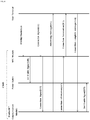
- FIG. 4 is a flow diagram illustrating messages transmitted and received in the continuous glucose monitoring system according to the present disclosure.
- the NFC module when the user terminal and the continuous glucose monitoring system are located within the first distance, the NFC module receives operating power from the user terminal in S10. An NFC module is also provided in the user terminal.
- the NFC module receiving the operating power from the user terminal starts to be operated, generates a first enable signal, and provides the generated first enable signal to the power switch in S20.
- the power switch is switched on in response to the first enable signal and provides power of the battery to the bluetooth communication module.
- the bluetooth communication module receives a connection signal from the user terminal through the NFC module in S31 and S33.
- the connection signal is generated in a dedicated application program of the user terminal and is provided to the continuous glucose monitoring system to start a pairing connection between the user terminal and the continuous glucose monitoring system.
- the bluetooth communication module generates an advertising message including an identifier of the continuous glucose monitoring system in response to the connection signal and transmits the generated advertising message to the user terminal in S40. After the bluetooth communication module transmits the advertising message to the user terminal, the bluetooth communication module transmits connection information to the user terminal through the NFC module in S51 and S53. A user may confirm the continuous glucose monitoring system displayed on the user terminal, on the basis of the advertising message, and may automatically perform a pairing connection using the connection information received through the NFC module.
- the bluetooth communication module When the bluetooth communication module receives a connection complete message from the user terminal in S60, the bluetooth communication module generates a second enable signal and provides the generated second enable signal to the power switch in S70. Until the pairing connection between the continuous glucose monitoring system and the user terminal is completed, the power switch is switched on in response to the first enable signal received from the NFC module and provides power of the battery to the bluetooth communication module. When the pairing connection between the continuous glucose monitoring system and the user terminal is completed, the power switch is switched on in response the second enable signal received from the bluetooth communication module and provides the power of the battery to the Bluetooth communication module.
- FIG. 5 is a set of diagrams illustrating an example of operation of a dedicated application program of the user terminal in the continuous glucose monitoring system according to the present disclosure.
- identifiers of devices which are searched for and are connectable, are displayed on the user terminal.
- the continuous glucose monitoring system and the user terminal are automatically paired and connected, on the basis of a received pin code.
- the continuous glucose monitoring system corresponding to a received pin code, among the connectable devices may be automatically selected, and thus, the user terminal and the continuous glucose monitoring system may be automatically paired and connected.
- the user terminal receives periodically measured blood glucose information from the continuous glucose monitoring system and displays the received blood glucose information to the user.
Landscapes
- Health & Medical Sciences (AREA)
- Life Sciences & Earth Sciences (AREA)
- Engineering & Computer Science (AREA)
- Physics & Mathematics (AREA)
- Animal Behavior & Ethology (AREA)
- Veterinary Medicine (AREA)
- Biophysics (AREA)
- Biomedical Technology (AREA)
- Heart & Thoracic Surgery (AREA)
- Medical Informatics (AREA)
- Molecular Biology (AREA)
- Surgery (AREA)
- Pathology (AREA)
- General Health & Medical Sciences (AREA)
- Public Health (AREA)
- Hematology (AREA)
- Emergency Medicine (AREA)
- Optics & Photonics (AREA)
- Computer Networks & Wireless Communication (AREA)
- Measurement Of The Respiration, Hearing Ability, Form, And Blood Characteristics Of Living Organisms (AREA)
- Investigating Or Analysing Biological Materials (AREA)
- Measuring And Recording Apparatus For Diagnosis (AREA)
- Telephone Function (AREA)
- Medical Treatment And Welfare Office Work (AREA)
- Management, Administration, Business Operations System, And Electronic Commerce (AREA)
Abstract
Description
- The present disclosure relates to an apparatus for controlling operations of a continuous glucose monitoring system. More specifically, in the apparatus for controlling operations of the continuous glucose monitoring system, when a continuous glucose monitoring system is located within a certain distance of a user terminal, power of a battery can be supplied to the continuous glucose monitoring system through a power switch switched on in response to an enable signal generated by a near field communication module, thereby starting operations of the continuous glucose monitoring system without user intervention. The near field communication module can provide connection information to the user terminal, thereby automatically performing a pairing connection with the user terminal using the near field communication module and a bluetooth communication module. When the pairing connection with the user terminal is completed, an enable signal generated by the bluetooth communication module can be provided to the power switch, thereby maintaining the pairing connection with the user terminal, even when the user terminal is outside of a range for near field communication.
- Diabetes is a chronic disease common in modern people. In the Republic of Korea, two million or more people, about 5% of the total population, suffer from diabetes.
- Diabetes is caused by the pancreas producing an entirely, or relatively, insufficient amount of insulin due to a variety of reasons, such as obesity, stress, and bad eating habits, and due to congenital or hereditary reasons, so that glucose levels are absolutely high in blood, instead of being balanced in blood.
- Blood contains a certain concentration of glucose, from which tissue cells produce energy.
- However, when glucose levels are higher than normal, glucose is not stored appropriately in the liver, muscles, or fat cells and excessive amounts of glucose remain in the blood. Thus, diabetic patients commonly have higher blood glucose levels than other people. Excessive amounts of blood glucose may be discharged in urine without being absorbed by body tissues. Accordingly, since the body tissues may fail to have sufficient amounts of glucose, necessary for normal functioning, the body tissues may malfunction.
- Diabetes has subtle or no subjective symptoms in the early stages of the disease. With the progression of the disease, however, the classic symptoms of diabetes, such as polydipsia, polyphagia, polyuria, weight loss, fatigue, itchy skin, and slow healing of cuts of the hands and feet, appear. Prolonged diabetes may cause complications, such as blurred vision, high blood pressure, nephropathy, palsy, periodontal diseases, muscle spasms, neuralgia, and gangrene.
- In order to diagnose and manage diabetes such that complications do not arise, systematic measurement of blood glucose should be carried out in concert with systematic treatment.
- For diabetic patients and people having higher blood glucose levels than normal, even though diabetes has not yet occurred, a number of medical device manufacturers provide various glucose monitoring systems such that blood glucose can be measured at home.
- The glucose monitoring device uses a method in which a user draws blood from a finger tip and performs a blood glucose measurement once and a method in which the glucose monitoring system is attached to a user's abdomen and arm and blood glucose measurement is continuously performed.
- Diabetic patients usually go through hyperglycemia and hypoglycemia. Emergencies may arise from the hypoglycemia, and diabetic patients may lose consciousness or even lose their life when hypoglycemia persists for an extended period of time without sugar supply. Therefore, immediate detection of hypoglycemia is very important for diabetic patients, but invasive glucose monitoring devices that intermittently measure blood glucose have limitations in accurately detecting hypoglycemia.
- Recently, in order to overcome such limitations, continuous glucose monitoring systems (CGMSs) have been developed, which are inserted into the human body to measure a blood glucose level at an interval of several minutes, thereby assisting diabetic patients in managing and coping with emergency situations.
- Invasive glucose monitoring systems measure blood glucose through a method in which a diabetic patient collects blood by stabbing a pain-sensitive finger tip with a needle to check blood glucose thereof, which may causes pain and repulsion when blood is collected. In order to minimize pain and repulsion, research and development are being conducted into CGMSs that continuously measure blood glucose after a needle-shaped sensor is inserted into a part of the abdomen, the arm, or the like which is relatively less sensitive to pain.
- The CGMS includes a sensor module attached to the skin of the body to extract a body fluid and measure blood glucose and a transmitter configured to transmit a blood glucose level measured by the sensor module to a user terminal. The user terminal is provided with a dedicated application program for managing blood glucose information received from the CGMS. A user may check the measured blood glucose information through the dedicated application program of the user terminal.
- In order to receive the blood glucose information and check the received blood glucose information through the user terminal, a process for establishing communication channel between the CGMS and the user terminal should be primarily performed. Typically, the user terminal and the CGMS are paired and connected using Bluetooth communication and then communicate with each other.
- The CGMS has the expiration date about two weeks. In order to pair and connect the CGMS to the user terminal, a user should directly input pairing connection information to the user terminal every time. Furthermore, in the case of a user such as a senior citizen or an infant who is unfamiliar with a process of pairing and connecting the user terminal and the CGMS, due to an inexperience in operations, it may be difficult for the user to accurately measure blood glucose information or the user may not be able to measure blood glucose information during a set period due to limited battery power.
- Various aspects of the present disclosure provide an apparatus for controlling operations of a continuous glucose monitoring system. When a continuous glucose monitoring system is located within a certain distance of a user terminal, power of a battery can be supplied to the continuous glucose monitoring system through a power switch switched on in response to an enable signal generated by a near field communication module, thereby starting operation of the continuous glucose monitoring system.
- Also provided is an apparatus for controlling operations of a continuous glucose monitoring system, the apparatus being able to automatically perform a pairing connection with a user terminal using a near field communication module and a bluetooth communication module.
- Also provided is an apparatus for controlling operations of a continuous glucose monitoring system, the apparatus being able to maintain a pairing communication with a user terminal by providing an enable signal generated by a bluetooth communication module to a power switch when the pairing connection with the user terminal is completed.
- According to an aspect, an apparatus for controlling operations of a continuous glucose monitoring system may include: a near field wireless communication (NFC) module generating a first enable signal when power is supplied from a user terminal; a Bluetooth communication module; and a power switch switched on when the first enable signal is received from the NFC module and supplying power from a battery to the Bluetooth communication module, wherein the Bluetooth communication module transmits an advertising message to the user terminal when the power is supplied from the battery through the power switch.
- As set forth above, the Bluetooth communication module may be activated in response to a connection signal provided through the NFC module and may transmit the advertising message to the user terminal.
- As set forth above, the connection signal may be received from the user terminal through the NFC module.
- As set forth above, after the connection signal is transmitted to the Bluetooth communication module, the NFC module may transmit connection information to the user terminal.
- As set forth above, after the connection signal is provided to the Bluetooth communication module, the NFC module may transmit the connection information provided from the Bluetooth communication module to the user terminal.
- As set forth above, a connection complete signal is received from the user terminal, the Bluetooth communication module may maintain communication with the user terminal.
- As set forth above, when the connection complete message is received from the user terminal, the Bluetooth communication module may generate a second enable signal and may provide the generated second enable signal to the power switch.
- As set forth above, when at least one of the first enable signal, the second enable signal, or a combination thereof, is received, the power switch may be switched on to supply the power of the battery to the Bluetooth communication module.
- The apparatus for controlling operations of a continuous glucose monitoring system according to the present disclosure has the following effects.
- First, according to the apparatus for controlling operations of a continuous glucose monitoring system according to the present disclosure, when a continuous glucose monitoring system is located within a certain distance from a user terminal, power of the battery can be supplied to the continuous glucose monitoring system through the power switch switched on in response to an enable signal generated by the near field communication module, thereby starting operations of the continuous glucose monitoring system without separate user intervention.
- Second, in the apparatus for controlling operations of a continuous glucose monitoring system according to the present disclosure, the near field communication module provides connection information to a user terminal, a pairing connection with the user terminal is automatically performed using the near field communication module and the Bluetooth communication module.
- Third, in the apparatus for controlling operations of a continuous glucose monitoring system according to the present disclosure, when a pairing connection with a user terminal is completed, an enable signal generated by the Bluetooth communication module can be provided to the power switch, thereby maintaining the pairing connection with the user terminal even when the user terminal is out of a distance for short range communication.
- Fourth, in the apparatus for controlling operations of a continuous glucose monitoring system according to the present disclosure, when a user terminal is located at a short distance from a continuous glucose monitoring system, a pairing connection can be performed by transmitting connection information to the user terminal. Accordingly, information of the continuous glucose monitoring system can be transmitted only to a limited user terminal, thereby safely protecting user's personal information.
- The above and other objects, features, and advantages of the present disclosure will be more clearly understood from the following detailed description, taken in conjunction with the accompanying drawings, in which:
-
FIG. 1 is a diagram illustrating a continuous glucose monitoring system according to the present disclosure; -
FIG. 2 is a functional block diagram illustrating an apparatus for controlling operations of a continuous glucose monitoring system according to the present disclosure; -
FIG. 3 is a functional block diagram illustrating an example of a Bluetooth communication module according to the present disclosure; -
FIG. 4 is a flow diagram illustrating messages transmitted and received in the continuous glucose monitoring system according to the present disclosure; and -
FIG. 5 is a set of diagrams illustrating operation examples of a dedicated application program of a user terminal in the continuous blood glucose measurement system according to the present disclosure. -
FIG. 1 is a diagram illustrating a continuous glucose monitoring system. - Described in more detail with reference to
FIG. 1 , a continuousglucose monitoring system 100 is attached to a skin of auser 1 to periodically extract a body fluid of theuser 1 and continuously measure bioinformation of theuser 1, for example, a blood glucose level using the extracted body fluid. - The continuous
glucose monitoring system 100 and auser terminal 10 are connected to each other through short range communication, such as bluetooth communication or near field communication (NFC), to transmit and receive data through the short range communication. That is, when the continuousglucose monitoring system 100 and theuser terminal 10 are located within a range of the short range communication, the continuousglucose monitoring system 100 transmits measured bioinformation of theuser 1 to theuser terminal 10. Hereinafter, biometric information measured in the continuousglucose monitoring system 100 will be described by exemplifying blood glucose information. - More specifically, when the
user terminal 10 is adjacent to the continuousglucose monitoring system 100, an NFC module (not shown) provided in the continuousglucose monitoring system 100 starts to be operated by receiving power from theuser terminal 10. The operated NFC module starts to operate a bluetooth communication module (not shown) provided in the continuousglucose monitoring system 100. The continuousglucose monitoring system 100 automatically performs a communication connection procedure using the NFC module and the bluetooth communication module to be connected to and communicate with theuser terminal 10. When theuser terminal 10 and the continuousglucose monitoring system 100 are connected to each other, the continuousglucose monitoring system 100 periodically transmits measured blood glucose information of the user to theuser terminal 10. - Here, the
user terminal 10 is a device capable of storing or outputting the blood glucose information of theuser 1 received from the continuousglucose monitoring system 100 such that the blood glucose information may be checked and output to the user. A dedicated application program for managing blood glucose information may be executed in theuser terminal 10. As an example of such auser terminal 10, a smartphone, a notebook, a personal digital assistant (PDA), a blood glucose management dedicated terminal, or the like may be used. - The
user terminal 10 and amanagement server 50 are connected to each other via anetwork 30. Theuser terminal 10 transmits the blood glucose information of theuser 1, received from the continuousglucose monitoring system 100, to themanagement server 50 or transmits sensor use information of the continuousglucose monitoring system 100 to themanagement server 50. - Particularly, the
user terminal 10 identifies a user on the basis of inputted user information and registers the received blood glucose information by mapping the received blood glucose information to the identified user. In addition, theuser terminal 10 transmits the registered blood glucose information, mapped to the user, or transmits the sensor use information to themanagement server 50 together with the user information. -
FIG. 2 is a functional block diagram illustrating an apparatus for controlling operations of a continuous glucose monitoring system according to the present disclosure. - Described in more detail with reference to
FIG. 2 , when anNFC module 110 is located within a first distance at which theNFC module 110 may communicate with a user terminal, theNFC module 110 of a continuous glucose monitoring system receives operating power from the user terminal. TheNFC communication module 110 receiving the operation power generates a first enable signal EN1 and provides the first enable signal EN1 to apower switch 130. When the operating power is not received from the user terminal, theNFC module 110 does not generate an enable signal. Only when the operating power is received from the user terminal, does theNFC module 110 generate the first enable signal EN1. - The
power switch 130 controls connection between abattery 150 and abluetooth communication module 170 in response to a signal input to an enable terminal (not shown). When the first enable signal EN1 generated from theNFC module 110 is not inputted into the enable terminal, thepower switch 130 maintains a switched off state. When the first enable signal EN1 generated from theNFC module 110 is inputted into the enable terminal, thepower switch 130 is switched on to connect thebattery 150 and thebluetooth communication module 170 to each other. When thebattery 150 and thebluetooth communication module 170 are connected to each other through thepower switch 130, power is supplied from thebattery 150 to thebluetooth communication module 170. - When the power is supplied from the
battery 150 to thebluetooth communication module 170, thebluetooth communication module 170 starts to be operated. Thebluetooth communication module 170 first transmits an advertising message including an identifier of the continuous glucose monitoring system to the user terminal. After thebluetooth communication module 170 transmits the advertising message, thebluetooth communication module 170 controls theNFC module 110 to transmit connection information, for example, a pin code necessary for pairing and connecting the user terminal and the continuous glucose monitoring system to the user terminal. - When the pairing connection between the user terminal and the continuous glucose monitoring system is completed, the
bluetooth communication module 170 receives a connection complete message from the user terminal. When thebluetooth communication module 170 receives the connection complete message, thebluetooth communication module 170 generates a second enable signal and provides the generated second enable signal to an enable terminal of thepower switch 130. - When the
NFC module 110 of the continuous glucose monitoring system does not receive power from the user terminal, due to the distance between the user terminal and the continuous glucose monitoring system being greater than the first distance and, theNFC module 110 stops generating the first enable signal EN1. When thepower switch 130 receives at least one of the first enable signal EN1 and the second enable signal EN2 through the enable terminal, thepower switch 130 is switched on to connect thebattery 150 and thebluetooth communication module 170 to each other. After the pairing connection between the user terminal and the continuous glucose monitoring system is completed, thebluetooth communication module 170 may generate the second enable signal EN2 and may provide the second enable signal EN2 to an enable terminal of theNFC module 110. Thus, even when the distance between the user terminal and the continuous glucose monitoring system is out of the first distance, the power of thebattery 150 may be continuously supplied to thebluetooth communication module 170. -
FIG. 3 is a functional block diagram illustrating an example of thebluetooth communication module 170 according to the present disclosure. - Described in more detail with reference to
FIG. 3 , when a connection signal is received from the user terminal through the NFC module, acommunication connector 171 generates an advertising message and transmits the advertising message to the user terminal. Thecommunication connector 171 generates the advertising message by providing an identifier of the continuous glucose monitoring system stored in astorage 173. - After the
communication connector 171 transmits the advertising message, thecommunication connector 171 extracts connection information, such as a connection pin code of the continuous glucose monitoring system, stored in thestorage 173, and transmits the extracted connection information to the user terminal through the NFC module. The user terminal and the continuous glucose monitoring system are automatically paired and connected using the identifier of the continuous glucose monitoring system and the connection information. When thecommunication connector 171 receives a connection complete message from the user terminal, thecommunication connector 171 transmits connection complete information to apower connector 175. - When the
power connector 175 receives the connection complete information from thecommunication connector 171, thepower connector 175 generates the second enable signal EN2 and provides the generated second enable signal EN2 to the enable terminal of the power switch. -
FIG. 4 is a flow diagram illustrating messages transmitted and received in the continuous glucose monitoring system according to the present disclosure. - Described in more detail with reference to
FIG. 4 , when the user terminal and the continuous glucose monitoring system are located within the first distance, the NFC module receives operating power from the user terminal in S10. An NFC module is also provided in the user terminal. - The NFC module receiving the operating power from the user terminal starts to be operated, generates a first enable signal, and provides the generated first enable signal to the power switch in S20.
- The power switch is switched on in response to the first enable signal and provides power of the battery to the bluetooth communication module. The bluetooth communication module receives a connection signal from the user terminal through the NFC module in S31 and S33. Here, when the user terminal and the NFC module start communicating with each other, the connection signal is generated in a dedicated application program of the user terminal and is provided to the continuous glucose monitoring system to start a pairing connection between the user terminal and the continuous glucose monitoring system.
- The bluetooth communication module generates an advertising message including an identifier of the continuous glucose monitoring system in response to the connection signal and transmits the generated advertising message to the user terminal in S40. After the bluetooth communication module transmits the advertising message to the user terminal, the bluetooth communication module transmits connection information to the user terminal through the NFC module in S51 and S53. A user may confirm the continuous glucose monitoring system displayed on the user terminal, on the basis of the advertising message, and may automatically perform a pairing connection using the connection information received through the NFC module.
- When the bluetooth communication module receives a connection complete message from the user terminal in S60, the bluetooth communication module generates a second enable signal and provides the generated second enable signal to the power switch in S70. Until the pairing connection between the continuous glucose monitoring system and the user terminal is completed, the power switch is switched on in response to the first enable signal received from the NFC module and provides power of the battery to the bluetooth communication module. When the pairing connection between the continuous glucose monitoring system and the user terminal is completed, the power switch is switched on in response the second enable signal received from the bluetooth communication module and provides the power of the battery to the Bluetooth communication module.
-
FIG. 5 is a set of diagrams illustrating an example of operation of a dedicated application program of the user terminal in the continuous glucose monitoring system according to the present disclosure. - As illustrated in
FIG. 5A , when an advertising message is received from the continuous glucose monitoring system, identifiers of devices, which are searched for and are connectable, are displayed on the user terminal. In the present disclosure, when an identifier of the continuous glucose monitoring system among the connectable devices is selected by a user, the continuous glucose monitoring system and the user terminal are automatically paired and connected, on the basis of a received pin code. - According to fields to which the present disclosure is applied, even though the identifier of the continuous glucose monitoring system is not selected by the user, the continuous glucose monitoring system corresponding to a received pin code, among the connectable devices, may be automatically selected, and thus, the user terminal and the continuous glucose monitoring system may be automatically paired and connected.
- As illustrated in
FIG. 5B , the user terminal receives periodically measured blood glucose information from the continuous glucose monitoring system and displays the received blood glucose information to the user.
Claims (8)
- An apparatus for controlling operations of a continuous glucose monitoring system, the apparatus comprising:a near field wireless communication (NFC) module generating a first enable signal when power is supplied from a user terminal;a bluetooth communication module; anda power switch switched on and supplying power from a battery to the bluetooth communication module when the first enable signal is received from the NFC module,wherein the bluetooth communication module transmits an advertising message to the user terminal when the power is supplied from the battery through the power switch.
- The apparatus according to claim 1, wherein the bluetooth communication module is activated in response to a connection signal provided through the NFC module and transmits the advertising message to the user terminal.
- The apparatus according to claim 2, wherein the connection signal is received from the user terminal through the NFC module.
- The apparatus according to claim 2, wherein, after the connection signal is transmitted to the bluetooth communication module, the NFC module transmits connection information to the user terminal.
- The apparatus according to claim 4, wherein, after the connection signal is provided to the bluetooth communication module, the NFC module transmits the connection information provided from the bluetooth communication module to the user terminal.
- The apparatus according to claim 1, wherein, when a connection complete signal is received from the user terminal, the bluetooth communication module maintains communication with the user terminal.
- The apparatus according to claim 6, wherein, when the connection complete message is received from the user terminal, the bluetooth communication module generates a second enable signal and provides the generated second enable signal to the power switch.
- The apparatus according to claim 7, wherein, when at least one of the first enable signal and the second enable signal is received, the power switch is switched on to supply the power of the battery to the bluetooth communication module.
Applications Claiming Priority (2)
| Application Number | Priority Date | Filing Date | Title |
|---|---|---|---|
| KR1020180091868A KR102200139B1 (en) | 2018-08-07 | 2018-08-07 | Apparatus for controlling operation of CGMS |
| PCT/KR2019/007511 WO2020032382A1 (en) | 2018-08-07 | 2019-06-21 | Apparatus for controlling operation of continuous blood glucose tester |
Publications (3)
| Publication Number | Publication Date |
|---|---|
| EP3653123A1 true EP3653123A1 (en) | 2020-05-20 |
| EP3653123A4 EP3653123A4 (en) | 2021-03-31 |
| EP3653123B1 EP3653123B1 (en) | 2024-11-13 |
Family
ID=69415249
Family Applications (1)
| Application Number | Title | Priority Date | Filing Date |
|---|---|---|---|
| EP19845690.7A Active EP3653123B1 (en) | 2018-08-07 | 2019-06-21 | Apparatus for controlling operation of continuous blood glucose tester |
Country Status (7)
| Country | Link |
|---|---|
| US (1) | US12220232B2 (en) |
| EP (1) | EP3653123B1 (en) |
| JP (2) | JP7212141B2 (en) |
| KR (1) | KR102200139B1 (en) |
| AU (2) | AU2019318970B2 (en) |
| NZ (1) | NZ773218A (en) |
| WO (1) | WO2020032382A1 (en) |
Families Citing this family (5)
| Publication number | Priority date | Publication date | Assignee | Title |
|---|---|---|---|---|
| KR102569413B1 (en) * | 2020-12-14 | 2023-08-24 | 주식회사 아이센스 | Sensor unit for continuous glucose monitoring system |
| KR102438798B1 (en) * | 2021-12-22 | 2022-09-01 | 제일기술(주) | Continuous blood glucose measurement device |
| KR102420940B1 (en) * | 2022-02-10 | 2022-07-14 | 네메시스 주식회사 | Continuous blood glucose measurement data receiving device, the control method thereof and the system comprising the same |
| KR20250015527A (en) | 2023-07-25 | 2025-02-03 | 주식회사 솔루엠 | Applicator built-in patch-type continuous blood glucose meter |
| KR20250015525A (en) | 2023-07-25 | 2025-02-03 | 주식회사 솔루엠 | Applicator built-in patch-type continuous blood glucose meter |
Family Cites Families (26)
| Publication number | Priority date | Publication date | Assignee | Title |
|---|---|---|---|---|
| DE102005019306B4 (en) | 2005-04-26 | 2011-09-01 | Disetronic Licensing Ag | Energy-optimized data transmission of a medical device |
| US20080119705A1 (en) * | 2006-11-17 | 2008-05-22 | Medtronic Minimed, Inc. | Systems and Methods for Diabetes Management Using Consumer Electronic Devices |
| US9402544B2 (en) | 2009-02-03 | 2016-08-02 | Abbott Diabetes Care Inc. | Analyte sensor and apparatus for insertion of the sensor |
| US10911515B2 (en) * | 2012-05-24 | 2021-02-02 | Deka Products Limited Partnership | System, method, and apparatus for electronic patient care |
| CA2766685A1 (en) | 2010-03-24 | 2011-12-29 | Abbott Diabetes Care Inc. | Medical device inserters and processes of inserting and using medical devices |
| JP5635381B2 (en) | 2010-12-07 | 2014-12-03 | 株式会社ピコ・ラボ | Authentication method, management apparatus, and authentication system |
| KR20120069262A (en) * | 2010-12-20 | 2012-06-28 | 삼성전자주식회사 | Dongle device for operating external input device and external input system including the same, and operating method for external input device |
| WO2014070254A1 (en) | 2012-11-01 | 2014-05-08 | Blue Spark Technologies, Inc. | Body temperature logging patch |
| US9110897B2 (en) | 2012-11-16 | 2015-08-18 | Electronics And Telecommunications Research Institute | Sensor tag and method of providing service using the same |
| US20140253323A1 (en) * | 2013-03-06 | 2014-09-11 | Lifescan, Inc. | Low analyte level alert system from continuous analyte monitor |
| US20140273824A1 (en) * | 2013-03-15 | 2014-09-18 | Medtronic, Inc. | Systems, apparatus and methods facilitating secure pairing of an implantable device with a remote device using near field communication |
| WO2014179343A1 (en) | 2013-04-30 | 2014-11-06 | Abbott Diabetes Care Inc. | Systems, devices, and methods for energy efficient electrical device activation |
| US20170091412A1 (en) | 2014-05-30 | 2017-03-30 | Apple Inc. | Systems and Methods for Facilitating Health Research Using a Personal Wearable Device With Multiple Pairing Configurations |
| US20170331524A1 (en) * | 2014-11-18 | 2017-11-16 | Mc10, Inc. | System, device, and method for electronic device activation |
| KR20160066930A (en) * | 2014-12-03 | 2016-06-13 | 한국전자통신연구원 | Method and apparatus for measurement of electrocardiogram based on NFC tag |
| KR20160070924A (en) * | 2014-12-10 | 2016-06-21 | 재단법인 다차원 스마트 아이티 융합시스템 연구단 | Apparatus and method for measuring using near field communication and biosensor using the same |
| AU2016209318A1 (en) * | 2015-01-21 | 2017-04-20 | Dexcom, Inc. | Continuous glucose monitor communication with multiple display devices |
| JP2016139917A (en) | 2015-01-27 | 2016-08-04 | キヤノン株式会社 | Radio communication apparatus and radio communication method |
| KR20170050656A (en) | 2015-10-30 | 2017-05-11 | 삼성전자주식회사 | Wireless power receiver and method for controlling thereof |
| KR102472489B1 (en) * | 2015-11-02 | 2022-12-01 | 삼성전자주식회사 | Electonic apparatus, system and the controlling method thereof |
| CN205232211U (en) | 2015-12-18 | 2016-05-11 | 深圳市宏电技术股份有限公司 | Low -power consumption, high transmission rate's wearable equipment and data transmission system thereof |
| EP4277322A3 (en) | 2016-07-20 | 2024-01-24 | Dexcom, Inc. | System and method for wireless communication of glucose data |
| US9967001B2 (en) * | 2016-07-25 | 2018-05-08 | Verily Life Sciences Llc | Systems and methods for passive radio enabled power gating for a body mountable device |
| US10896245B2 (en) | 2016-08-29 | 2021-01-19 | Bigfoot Biomedical, Inc. | Network topology for insulin pump systems |
| KR101869238B1 (en) * | 2016-11-08 | 2018-06-20 | 건양대학교산학협력단 | Bio Information Sensing Device and Patient Management Method Using It |
| AU2017388066B9 (en) | 2016-12-27 | 2021-04-01 | Dexcom, Inc. | Systems and methods for patient monitoring using an HCP - specific device |
-
2018
- 2018-08-07 KR KR1020180091868A patent/KR102200139B1/en active Active
-
2019
- 2019-06-21 AU AU2019318970A patent/AU2019318970B2/en active Active
- 2019-06-21 WO PCT/KR2019/007511 patent/WO2020032382A1/en not_active Ceased
- 2019-06-21 JP JP2021506293A patent/JP7212141B2/en active Active
- 2019-06-21 EP EP19845690.7A patent/EP3653123B1/en active Active
- 2019-06-21 NZ NZ773218A patent/NZ773218A/en unknown
- 2019-06-21 US US17/264,796 patent/US12220232B2/en active Active
-
2022
- 2022-09-14 AU AU2022231711A patent/AU2022231711A1/en not_active Abandoned
-
2023
- 2023-01-12 JP JP2023003164A patent/JP2023040230A/en active Pending
Also Published As
| Publication number | Publication date |
|---|---|
| KR102200139B1 (en) | 2021-01-08 |
| JP2022503522A (en) | 2022-01-12 |
| AU2019318970A1 (en) | 2021-03-04 |
| US12220232B2 (en) | 2025-02-11 |
| KR20200016590A (en) | 2020-02-17 |
| EP3653123B1 (en) | 2024-11-13 |
| AU2019318970B2 (en) | 2022-06-23 |
| AU2022231711A1 (en) | 2022-10-06 |
| WO2020032382A1 (en) | 2020-02-13 |
| US20210290118A1 (en) | 2021-09-23 |
| EP3653123A4 (en) | 2021-03-31 |
| JP7212141B2 (en) | 2023-01-24 |
| JP2023040230A (en) | 2023-03-22 |
| NZ773218A (en) | 2022-07-29 |
Similar Documents
| Publication | Publication Date | Title |
|---|---|---|
| AU2019318970B2 (en) | Apparatus for controlling operation of continuous blood glucose tester | |
| US10939859B2 (en) | Mitigating single point failure of devices in an analyte monitoring system and methods thereof | |
| US20110118578A1 (en) | Hypoglycemic treatment methods and systems | |
| US11284816B2 (en) | Multi-analyte continuous glucose monitoring | |
| GB2436721A (en) | Automated method for adapting the settings of a patient monitor | |
| US20190021659A1 (en) | Wireless Medical Evaluation Device | |
| CN111601543A (en) | Method for managing biometric information using sensor usage information | |
| CN112996429A (en) | System for the immediate personalized treatment of patients in medical emergencies | |
| KR102438798B1 (en) | Continuous blood glucose measurement device | |
| KR20210015190A (en) | Glucose monitoring device based on electrocardiogram measurement | |
| US12070328B2 (en) | Wearable personal healthcare sensor apparatus | |
| Vonteddu et al. | Smart Wearable Wristband for Patients' Health Monitoring System through IoT | |
| KR20160133820A (en) | System for urgent rescue using portable device and treating service of urgent rescue | |
| AU2019220110B2 (en) | Continuous biometric information measuring device using sensor usage information stored in memory | |
| KR20190047808A (en) | Management system and method of pulse oximeter | |
| JP2014038489A (en) | Prescription information management device, prescription information management system, and prescription information management device control method | |
| KR102470263B1 (en) | ICT-based two-way communication and user blood glucose measurement management system | |
| CN105447802A (en) | Wearable diabetes patient management system | |
| CN213097821U (en) | Pressure pain diagnosis and treatment system | |
| US20190059729A1 (en) | Signaling device for cathetering requirement | |
| JP2019154573A (en) | Biological information system | |
| Jones et al. | Wireless Communication and Control System for Portable Micro-Electromechanical Device for Real-Time Blood Sampling and Glucose Analysis (Electronic Mosquito) | |
| Sudhindra et al. | A low cost real time ambulatory blood presure monitoring & alert system with GSM & GPS |
Legal Events
| Date | Code | Title | Description |
|---|---|---|---|
| STAA | Information on the status of an ep patent application or granted ep patent |
Free format text: STATUS: UNKNOWN |
|
| STAA | Information on the status of an ep patent application or granted ep patent |
Free format text: STATUS: THE INTERNATIONAL PUBLICATION HAS BEEN MADE |
|
| PUAI | Public reference made under article 153(3) epc to a published international application that has entered the european phase |
Free format text: ORIGINAL CODE: 0009012 |
|
| STAA | Information on the status of an ep patent application or granted ep patent |
Free format text: STATUS: REQUEST FOR EXAMINATION WAS MADE |
|
| 17P | Request for examination filed |
Effective date: 20200211 |
|
| AK | Designated contracting states |
Kind code of ref document: A1 Designated state(s): AL AT BE BG CH CY CZ DE DK EE ES FI FR GB GR HR HU IE IS IT LI LT LU LV MC MK MT NL NO PL PT RO RS SE SI SK SM TR |
|
| AX | Request for extension of the european patent |
Extension state: BA ME |
|
| RIN1 | Information on inventor provided before grant (corrected) |
Inventor name: YOU, CHOONG BEOM Inventor name: LEE, HA NA Inventor name: PARK, HYO SEON Inventor name: LEE, JIN WON |
|
| A4 | Supplementary search report drawn up and despatched |
Effective date: 20210301 |
|
| RIC1 | Information provided on ipc code assigned before grant |
Ipc: A61B 5/145 20060101ALI20210223BHEP Ipc: A61B 5/00 20060101ALI20210223BHEP Ipc: A61B 5/15 20060101AFI20210223BHEP |
|
| DAV | Request for validation of the european patent (deleted) | ||
| DAX | Request for extension of the european patent (deleted) | ||
| STAA | Information on the status of an ep patent application or granted ep patent |
Free format text: STATUS: EXAMINATION IS IN PROGRESS |
|
| 17Q | First examination report despatched |
Effective date: 20230531 |
|
| GRAP | Despatch of communication of intention to grant a patent |
Free format text: ORIGINAL CODE: EPIDOSNIGR1 |
|
| STAA | Information on the status of an ep patent application or granted ep patent |
Free format text: STATUS: GRANT OF PATENT IS INTENDED |
|
| INTG | Intention to grant announced |
Effective date: 20240801 |
|
| GRAS | Grant fee paid |
Free format text: ORIGINAL CODE: EPIDOSNIGR3 |
|
| GRAA | (expected) grant |
Free format text: ORIGINAL CODE: 0009210 |
|
| STAA | Information on the status of an ep patent application or granted ep patent |
Free format text: STATUS: THE PATENT HAS BEEN GRANTED |
|
| AK | Designated contracting states |
Kind code of ref document: B1 Designated state(s): AL AT BE BG CH CY CZ DE DK EE ES FI FR GB GR HR HU IE IS IT LI LT LU LV MC MK MT NL NO PL PT RO RS SE SI SK SM TR |
|
| REG | Reference to a national code |
Ref country code: GB Ref legal event code: FG4D |
|
| REG | Reference to a national code |
Ref country code: CH Ref legal event code: EP |
|
| REG | Reference to a national code |
Ref country code: DE Ref legal event code: R096 Ref document number: 602019062035 Country of ref document: DE |
|
| REG | Reference to a national code |
Ref country code: IE Ref legal event code: FG4D |
|
| REG | Reference to a national code |
Ref country code: LT Ref legal event code: MG9D |
|
| REG | Reference to a national code |
Ref country code: NL Ref legal event code: MP Effective date: 20241113 |
|
| PG25 | Lapsed in a contracting state [announced via postgrant information from national office to epo] |
Ref country code: HR Free format text: LAPSE BECAUSE OF FAILURE TO SUBMIT A TRANSLATION OF THE DESCRIPTION OR TO PAY THE FEE WITHIN THE PRESCRIBED TIME-LIMIT Effective date: 20241113 Ref country code: PT Free format text: LAPSE BECAUSE OF FAILURE TO SUBMIT A TRANSLATION OF THE DESCRIPTION OR TO PAY THE FEE WITHIN THE PRESCRIBED TIME-LIMIT Effective date: 20250313 Ref country code: IS Free format text: LAPSE BECAUSE OF FAILURE TO SUBMIT A TRANSLATION OF THE DESCRIPTION OR TO PAY THE FEE WITHIN THE PRESCRIBED TIME-LIMIT Effective date: 20250313 |
|
| PG25 | Lapsed in a contracting state [announced via postgrant information from national office to epo] |
Ref country code: NL Free format text: LAPSE BECAUSE OF FAILURE TO SUBMIT A TRANSLATION OF THE DESCRIPTION OR TO PAY THE FEE WITHIN THE PRESCRIBED TIME-LIMIT Effective date: 20241113 Ref country code: FI Free format text: LAPSE BECAUSE OF FAILURE TO SUBMIT A TRANSLATION OF THE DESCRIPTION OR TO PAY THE FEE WITHIN THE PRESCRIBED TIME-LIMIT Effective date: 20241113 |
|
| REG | Reference to a national code |
Ref country code: AT Ref legal event code: MK05 Ref document number: 1741004 Country of ref document: AT Kind code of ref document: T Effective date: 20241113 |
|
| PG25 | Lapsed in a contracting state [announced via postgrant information from national office to epo] |
Ref country code: BG Free format text: LAPSE BECAUSE OF FAILURE TO SUBMIT A TRANSLATION OF THE DESCRIPTION OR TO PAY THE FEE WITHIN THE PRESCRIBED TIME-LIMIT Effective date: 20241113 |
|
| PG25 | Lapsed in a contracting state [announced via postgrant information from national office to epo] |
Ref country code: ES Free format text: LAPSE BECAUSE OF FAILURE TO SUBMIT A TRANSLATION OF THE DESCRIPTION OR TO PAY THE FEE WITHIN THE PRESCRIBED TIME-LIMIT Effective date: 20241113 |
|
| PG25 | Lapsed in a contracting state [announced via postgrant information from national office to epo] |
Ref country code: NO Free format text: LAPSE BECAUSE OF FAILURE TO SUBMIT A TRANSLATION OF THE DESCRIPTION OR TO PAY THE FEE WITHIN THE PRESCRIBED TIME-LIMIT Effective date: 20250213 |
|
| PG25 | Lapsed in a contracting state [announced via postgrant information from national office to epo] |
Ref country code: LV Free format text: LAPSE BECAUSE OF FAILURE TO SUBMIT A TRANSLATION OF THE DESCRIPTION OR TO PAY THE FEE WITHIN THE PRESCRIBED TIME-LIMIT Effective date: 20241113 Ref country code: GR Free format text: LAPSE BECAUSE OF FAILURE TO SUBMIT A TRANSLATION OF THE DESCRIPTION OR TO PAY THE FEE WITHIN THE PRESCRIBED TIME-LIMIT Effective date: 20250214 Ref country code: AT Free format text: LAPSE BECAUSE OF FAILURE TO SUBMIT A TRANSLATION OF THE DESCRIPTION OR TO PAY THE FEE WITHIN THE PRESCRIBED TIME-LIMIT Effective date: 20241113 |
|
| PG25 | Lapsed in a contracting state [announced via postgrant information from national office to epo] |
Ref country code: PL Free format text: LAPSE BECAUSE OF FAILURE TO SUBMIT A TRANSLATION OF THE DESCRIPTION OR TO PAY THE FEE WITHIN THE PRESCRIBED TIME-LIMIT Effective date: 20241113 |
|
| PG25 | Lapsed in a contracting state [announced via postgrant information from national office to epo] |
Ref country code: RS Free format text: LAPSE BECAUSE OF FAILURE TO SUBMIT A TRANSLATION OF THE DESCRIPTION OR TO PAY THE FEE WITHIN THE PRESCRIBED TIME-LIMIT Effective date: 20250213 |
|
| PG25 | Lapsed in a contracting state [announced via postgrant information from national office to epo] |
Ref country code: SM Free format text: LAPSE BECAUSE OF FAILURE TO SUBMIT A TRANSLATION OF THE DESCRIPTION OR TO PAY THE FEE WITHIN THE PRESCRIBED TIME-LIMIT Effective date: 20241113 |
|
| PGFP | Annual fee paid to national office [announced via postgrant information from national office to epo] |
Ref country code: DE Payment date: 20250402 Year of fee payment: 7 |
|
| PG25 | Lapsed in a contracting state [announced via postgrant information from national office to epo] |
Ref country code: DK Free format text: LAPSE BECAUSE OF FAILURE TO SUBMIT A TRANSLATION OF THE DESCRIPTION OR TO PAY THE FEE WITHIN THE PRESCRIBED TIME-LIMIT Effective date: 20241113 |
|
| PGFP | Annual fee paid to national office [announced via postgrant information from national office to epo] |
Ref country code: GB Payment date: 20250401 Year of fee payment: 7 |
|
| PG25 | Lapsed in a contracting state [announced via postgrant information from national office to epo] |
Ref country code: EE Free format text: LAPSE BECAUSE OF FAILURE TO SUBMIT A TRANSLATION OF THE DESCRIPTION OR TO PAY THE FEE WITHIN THE PRESCRIBED TIME-LIMIT Effective date: 20241113 |
|
| PG25 | Lapsed in a contracting state [announced via postgrant information from national office to epo] |
Ref country code: RO Free format text: LAPSE BECAUSE OF FAILURE TO SUBMIT A TRANSLATION OF THE DESCRIPTION OR TO PAY THE FEE WITHIN THE PRESCRIBED TIME-LIMIT Effective date: 20241113 |
|
| PG25 | Lapsed in a contracting state [announced via postgrant information from national office to epo] |
Ref country code: SK Free format text: LAPSE BECAUSE OF FAILURE TO SUBMIT A TRANSLATION OF THE DESCRIPTION OR TO PAY THE FEE WITHIN THE PRESCRIBED TIME-LIMIT Effective date: 20241113 |
|
| PG25 | Lapsed in a contracting state [announced via postgrant information from national office to epo] |
Ref country code: CZ Free format text: LAPSE BECAUSE OF FAILURE TO SUBMIT A TRANSLATION OF THE DESCRIPTION OR TO PAY THE FEE WITHIN THE PRESCRIBED TIME-LIMIT Effective date: 20241113 |
|
| PG25 | Lapsed in a contracting state [announced via postgrant information from national office to epo] |
Ref country code: IT Free format text: LAPSE BECAUSE OF FAILURE TO SUBMIT A TRANSLATION OF THE DESCRIPTION OR TO PAY THE FEE WITHIN THE PRESCRIBED TIME-LIMIT Effective date: 20241113 |
|
| REG | Reference to a national code |
Ref country code: DE Ref legal event code: R097 Ref document number: 602019062035 Country of ref document: DE |
|
| PG25 | Lapsed in a contracting state [announced via postgrant information from national office to epo] |
Ref country code: SE Free format text: LAPSE BECAUSE OF FAILURE TO SUBMIT A TRANSLATION OF THE DESCRIPTION OR TO PAY THE FEE WITHIN THE PRESCRIBED TIME-LIMIT Effective date: 20241113 |
|
| PLBE | No opposition filed within time limit |
Free format text: ORIGINAL CODE: 0009261 |
|
| STAA | Information on the status of an ep patent application or granted ep patent |
Free format text: STATUS: NO OPPOSITION FILED WITHIN TIME LIMIT |
|
| 26N | No opposition filed |
Effective date: 20250814 |
|
| REG | Reference to a national code |
Ref country code: CH Ref legal event code: H13 Free format text: ST27 STATUS EVENT CODE: U-0-0-H10-H13 (AS PROVIDED BY THE NATIONAL OFFICE) Effective date: 20260127 |
|
| PG25 | Lapsed in a contracting state [announced via postgrant information from national office to epo] |
Ref country code: MC Free format text: LAPSE BECAUSE OF FAILURE TO SUBMIT A TRANSLATION OF THE DESCRIPTION OR TO PAY THE FEE WITHIN THE PRESCRIBED TIME-LIMIT Effective date: 20241113 |
|
| PG25 | Lapsed in a contracting state [announced via postgrant information from national office to epo] |
Ref country code: LU Free format text: LAPSE BECAUSE OF NON-PAYMENT OF DUE FEES Effective date: 20250621 |
|
| REG | Reference to a national code |
Ref country code: BE Ref legal event code: MM Effective date: 20250630 |
|
| PG25 | Lapsed in a contracting state [announced via postgrant information from national office to epo] |
Ref country code: IE Free format text: LAPSE BECAUSE OF NON-PAYMENT OF DUE FEES Effective date: 20250621 |
|
| PG25 | Lapsed in a contracting state [announced via postgrant information from national office to epo] |
Ref country code: BE Free format text: LAPSE BECAUSE OF NON-PAYMENT OF DUE FEES Effective date: 20250630 |
|
| PG25 | Lapsed in a contracting state [announced via postgrant information from national office to epo] |
Ref country code: FR Free format text: LAPSE BECAUSE OF NON-PAYMENT OF DUE FEES Effective date: 20250630 |
|
| PG25 | Lapsed in a contracting state [announced via postgrant information from national office to epo] |
Ref country code: CH Free format text: LAPSE BECAUSE OF NON-PAYMENT OF DUE FEES Effective date: 20250630 |