EP3653050A1 - A locking mechanism - Google Patents
A locking mechanism Download PDFInfo
- Publication number
- EP3653050A1 EP3653050A1 EP19206378.2A EP19206378A EP3653050A1 EP 3653050 A1 EP3653050 A1 EP 3653050A1 EP 19206378 A EP19206378 A EP 19206378A EP 3653050 A1 EP3653050 A1 EP 3653050A1
- Authority
- EP
- European Patent Office
- Prior art keywords
- locking mechanism
- moveable
- support part
- component
- slidable
- Prior art date
- Legal status (The legal status is an assumption and is not a legal conclusion. Google has not performed a legal analysis and makes no representation as to the accuracy of the status listed.)
- Granted
Links
Images






Classifications
-
- A—HUMAN NECESSITIES
- A01—AGRICULTURE; FORESTRY; ANIMAL HUSBANDRY; HUNTING; TRAPPING; FISHING
- A01K—ANIMAL HUSBANDRY; AVICULTURE; APICULTURE; PISCICULTURE; FISHING; REARING OR BREEDING ANIMALS, NOT OTHERWISE PROVIDED FOR; NEW BREEDS OF ANIMALS
- A01K97/00—Accessories for angling
- A01K97/22—Platforms or seat-boxes specially adapted for angling, e.g. tackle boxes for use as seats
-
- A—HUMAN NECESSITIES
- A47—FURNITURE; DOMESTIC ARTICLES OR APPLIANCES; COFFEE MILLS; SPICE MILLS; SUCTION CLEANERS IN GENERAL
- A47C—CHAIRS; SOFAS; BEDS
- A47C4/00—Foldable, collapsible or dismountable chairs
-
- A—HUMAN NECESSITIES
- A47—FURNITURE; DOMESTIC ARTICLES OR APPLIANCES; COFFEE MILLS; SPICE MILLS; SUCTION CLEANERS IN GENERAL
- A47C—CHAIRS; SOFAS; BEDS
- A47C7/00—Parts, details, or accessories of chairs or stools
- A47C7/002—Chair or stool bases
- A47C7/008—Chair or stool bases for uneven surfaces
Definitions
- the present invention relates to a locking mechanism, especially but not exclusively a footplate locking mechanism for an angler's seat.
- One construction with such a mechanism which has been provided hitherto comprises a main seat-supporting frame having a footplate which can be slid out from and retracted back into the frame.
- the locking mechanism releasably retains the footplate selectively in its extended or retracted position.
- the locking mechanism is located at the side of the frame, as a result of which one hand of a user is needed to operate the locking mechanism whilst the user's other hand slides the footplate into or out of the frame. This operation can be cumbersome especially for an angler trying to cope with uneven ground.
- the present invention seeks to provide a remedy.
- the present invention is directed to a locking mechanism comprising a fixed component which is secured to a support part when the mechanism is fitted for use, and a slide component which when the mechanism is fitted for use is secured to a slidable part which can be extended from and retracted back into such a support part, the slide component having an operable part which when the mechanism is fitted for use is at a front portion of such a slidable part which the user holds to extend and retract the slidable part, there being interengaging portions of the fixed component and the slide component which interengage to hold such a slidable part in position relative to such a support part when the mechanism is fitted for use, and there being at least one moveable member of one of the said fixed and slide components moveable directly or indirectly by means of the said operable part to disengage the said interengaging portions thereby to enable such a slidable part to be extended from or retracted into such a support part when the mechanism is in use.
- This provides the advantage that a user can both disengage the interengaging portions and slide such a slidable part out from or back into such a support part at the same time with one hand.
- the said operable part may be sprung-loaded towards a condition in which it will not cause the interengaging portions to disengage when the mechanism is in use.
- the said at least one moveable member may be a member of the said fixed component.
- Such a construction may reduce the amount of material required for the mechanism to be operable.
- the said at least one moveable member may be sprung loaded towards an engagement positon.
- the said slide component may be provided with at least one aperture located to receive the said moveable member with a given position of such a slidable part relative to such a moveable part, to lock those two parts in position relative to one another.
- the said slide component may have a cam portion connected to the operable part to be moved thereby into and out of a position in which it will cause the interengaging portions to disengage, or to inhibit engagement therebetween.
- This provides a simple and therefor inexpensive way of making the locking mechanism effective.
- the said fixed component may have a moveable cam portion fixed relative to the said moveable member, the moveable cam portion being moved by the cam portion of the said slide component so as to move the said moveable member out of engagement with the interengaging portion of the slide component, or so as to inhibit engagement of the said moveable member with the interengaging portion of the slide component, when the said operable part is operated.
- the slide component may be elongate with more than one such aperture spaced apart along its length, the cam portion of the slide component being provided with respective cams for the apertures.
- a pair of moveable members each being as the said moveable member, receivable in one or more pairs of apertures each being as the said at least one aperture, each pair being spaced apart across the direction of movement of such a slideable part relative to such a support part when the mechanism is fitted for use.
- the present invention extends to such a support part having such a slidable part which can be extended from and retracted into the support part, these two parts being fitted with a locking mechanism in accordance with the present invention.
- the support part may be adapted to support an angler's tackle box as a seat, and the slidable part may constitute a footplate.
- the footplate may be provided with a cover to protect the locking mechanism from the ingress of dirt and fish bait.
- the angler's seat support 10 shown in Figures 1 to 11 comprises an aluminium seat support frame 12 constituting a support part.
- the frame 12 itself has two mutually parallel elongate base channel sections 14 having respective inwardly facing channels 16. These are fixed together at their respective rear ends by a transverse rear section 18.
- Two curved arm sections 20 extend upwardly from the respective front ends of the base sections 14 and then rearwardly, horizontally and slightly towards one another.
- Mutually parallel tubular sections 21a and 21b extend transversely and create a structural unit with the arms 20 to which they are welded, one, 21a, across the front ends of the horizontal portions of the arm sections 20, and the other, 21b, across the rear ends thereof.
- the rear tubular section, 21b is further supported by a strut 24 extending upwardly from the middle of the transverse section 18 to which it is welded to the middle of the rear section 21b to which it is also welded.
- Slanting decorative covers 26 are provided at opposite ends of the strut 24, extending between the strut 24 and the frame part 22 at the upper end of the strut 24, and between the rear transverse section 18 and the strut 24 at the lower end thereof.
- the width of the strut 24 reinforces the frame 12 against a parallelogram collapse.
- Plastics material connectors 22 extend from respective ends of the tubular section 21a to respective ends of the tubular section 21b, and are adapted to support an angler's box (not shown) itself adapted to act as a seat for an angler as well as to contain fishing equipment.
- Clamps 28 are fixed to and extend outwardly from the front and rear ends of the two base channel sections 14.
- Each clamp 28 holds a generally upright leg 30 by a clamp screw 32 in a releasable fashion.
- the clamp screw 32 can be loosened to enable the leg to be moved downwardly relative to the support frame 12 to any selected extent, whereafter the clamp screw 32 can be tightened to hold the leg in that selected degree of extension. In this way uneven ground can be accommodated, so that the legs support the base channel sections 14 in a horizontal condition even on uneven ground.
- Respective generally planar generally circular feet 34 are attached to the lower ends of the legs 30 by way of ball-and-socket joints 36 so that the feet can swivel relative to the leg 30 to accommodate any slope in the ground at the base of the leg 30.
- the feet 34 are especially adapted to resist sinking of the leg 30 into the ground, which is a hazard often encountered especially if the ground is soft.
- a generally rectangular footplate 40 having two parallel horizontal side sections 42 and a multiplicity of transverse sections 44 connecting the side sections 40 together has it side sections 42 received slidably within the channels 16 of the base sections 14, so that the footplate 40 as a whole can be extended out from and retracted back into the seat support frame 12.
- a front transverse section 46 of the footplate 40 extends outwardly beyond the side sections 42 to provide two further clamps 28 with clamp screws 32 releasably securing legs 30 with feet 34 in the same manner and for the same purpose as the clamps 28 and legs 30 attached to the main support 12.
- a front transverse section 50 of the seat support frame 12 has a fixed component 52 of a locking mechanism 53 attached to its underside, with moveable members in the form of two pins 54 spaced apart from one another transversely in relation to the direction of movement of the footplate 40 relative to the seat support 12, with rounded upper ends 56 of the pins 54 protruding upwardly through the section 50.
- the pins 54 are rigidly fixed to a transversely extending flange 57.
- a cam part 58 extends upwardly from the centre of the flange 57, midway between the pins 54.
- the cam part 58 has a rearwardly facing edge 59 which slants at an angle of 45° relative to the horizontal.
- Through-holes 60 in a support plate 62 of the component 52 receive lower ends of the pins 54, and through-holes 64 through the flange 57 on opposite sides of the cam part 58 receive upper ends of guide pegs 66 which are fixed to and extend upwardly from the support plate 62.
- Helical compression springs 68 are located between and urge apart the support plate 62 and the flange 57.
- the section 50 has an upper wall 70 and a lower wall 72.
- the upper side of the support plate 62 of the fixed component 52 is secured to the lower surface of the lower wall 72 where there is an aperture 74 upwardly through which extend the parts of the component 52 which are supported by the plate 62.
- the upper wall 70 is provided with two through-holes 76 through which the pins 54 extend upwardly, and a slot 78 through which the cam part 58 extends upwardly.
- the flange 57 is urged upwardly against the lower side of the upper wall 70 by the compression springs 68.
- an elongate slide component 80 of the locking mechanism 53 in the form of a runner type profile, attached to the underside of the footplate 40. It extends centrally from the front to the back of the footplate 40 and has two elongate ridges 82 in which a first pair of apertures 84 is formed towards the rear ends of the ridges 82, the apertures of the pair being formed in respective ones of the ridges 82 and being formed in registration with one another and spaced apart transversely of the component 80. A further such pair of apertures 86 is formed towards the forward ends of the ridges 82.
- a release rod 88 is retained within the elongate slide component 80 in such a fashion as to be moveable between a rearward non-release position (as shown in Figure 11 for example) and a forward release position.
- a finger grip 90 in the form of a T-bar profile on the underside of a handle 92 of the footplate 40 at the front thereof is fixed to the release rod 88.
- a compression spring 94 is located between and urges apart an abutment 96 which is fixed relative to the ridges 82 and an abutment 98 which is fixed relative to the release rod 88, so that the compression spring 94 urges the release rod 88 into its non-release position.
- Respective rounded cam parts 100 associated with the two pairs of apertures 84 and 86 are provided on the underside of the cam rod 88, protruding downwardly therefrom and located thereon such that they are offset rearwardly of the apertures when the release rod 88 is in its rearward non-release position.
- the user When the user wishes to retract the footplate 40 into the seat support frame 12 for stowage or to move the seat support 10 to a different location, the user places the palm of one hand against the handle 92 whilst inserting the fingers of the same hand behind the finger grip 90. With a squeezing action of the hand, the user now moves the release rod 88 against the restoring force of the compression spring 94 into its forward release position. As a result, the rearward cam part 100 engages the slanting edge 59 of the cam part 58 and urges it downwardly with further relative forward movement of the release rod 88.
- a similar operation enables the user to extend the footplate 40.
- the user squeezes the finger grip 90 towards the handle 92 to operate the release rod 88, pulls the footplate 40 out from the support frame 12, releasing the finger grip once the pins 54 are clear of the apertures 86, so that they will snap into the apertures 84 once the footplate 40 is in the fully extended position so that the locking mechanism 53 locks the footplate 40 in that position.
- a cover plate 110 may be provided over the footrest 40 to protect the locking mechanism 53 from the ingress of dirt or angler bait when in use, as shown in Figure 5 .
- a one or more further pairs of apertures may be provided in the ridges 82 to enable the user to lock the footplate 40 in one or more intermediate positions relative to the support frame 12 between the fully extended and fully retracted positions.
Landscapes
- Life Sciences & Earth Sciences (AREA)
- Environmental Sciences (AREA)
- Animal Husbandry (AREA)
- Biodiversity & Conservation Biology (AREA)
- Seats For Vehicles (AREA)
- Passenger Equipment (AREA)
Abstract
Description
- The present invention relates to a locking mechanism, especially but not exclusively a footplate locking mechanism for an angler's seat.
- One construction with such a mechanism which has been provided hitherto comprises a main seat-supporting frame having a footplate which can be slid out from and retracted back into the frame. The locking mechanism releasably retains the footplate selectively in its extended or retracted position. The locking mechanism is located at the side of the frame, as a result of which one hand of a user is needed to operate the locking mechanism whilst the user's other hand slides the footplate into or out of the frame. This operation can be cumbersome especially for an angler trying to cope with uneven ground.
- The present invention seeks to provide a remedy.
- Accordingly the present invention is directed to a locking mechanism comprising a fixed component which is secured to a support part when the mechanism is fitted for use, and a slide component which when the mechanism is fitted for use is secured to a slidable part which can be extended from and retracted back into such a support part, the slide component having an operable part which when the mechanism is fitted for use is at a front portion of such a slidable part which the user holds to extend and retract the slidable part, there being interengaging portions of the fixed component and the slide component which interengage to hold such a slidable part in position relative to such a support part when the mechanism is fitted for use, and there being at least one moveable member of one of the said fixed and slide components moveable directly or indirectly by means of the said operable part to disengage the said interengaging portions thereby to enable such a slidable part to be extended from or retracted into such a support part when the mechanism is in use.
- This provides the advantage that a user can both disengage the interengaging portions and slide such a slidable part out from or back into such a support part at the same time with one hand.
- The said operable part may be sprung-loaded towards a condition in which it will not cause the interengaging portions to disengage when the mechanism is in use.
- This provides the advantage that the user may operate the operable part into a condition in which it does cause the interengaging portions to disengage by a squeezing action against the spring-loading.
- The said at least one moveable member may be a member of the said fixed component.
- Such a construction may reduce the amount of material required for the mechanism to be operable.
- The said at least one moveable member may be sprung loaded towards an engagement positon.
- As a result the locking mechanism will tend to lock such a slidable part relative to such a support part in the absence of any operation of the said operable part.
- The said slide component may be provided with at least one aperture located to receive the said moveable member with a given position of such a slidable part relative to such a moveable part, to lock those two parts in position relative to one another.
- The said slide component may have a cam portion connected to the operable part to be moved thereby into and out of a position in which it will cause the interengaging portions to disengage, or to inhibit engagement therebetween.
- This provides a simple and therefor inexpensive way of making the locking mechanism effective.
- The said fixed component may have a moveable cam portion fixed relative to the said moveable member, the moveable cam portion being moved by the cam portion of the said slide component so as to move the said moveable member out of engagement with the interengaging portion of the slide component, or so as to inhibit engagement of the said moveable member with the interengaging portion of the slide component, when the said operable part is operated.
- The slide component may be elongate with more than one such aperture spaced apart along its length, the cam portion of the slide component being provided with respective cams for the apertures.
- This enables such a slidable part to be locked in more than one position relative to such a support part.
- There may be a pair of moveable members each being as the said moveable member, receivable in one or more pairs of apertures each being as the said at least one aperture, each pair being spaced apart across the direction of movement of such a slideable part relative to such a support part when the mechanism is fitted for use.
- This improves the stability of the mechanism.
- The present invention extends to such a support part having such a slidable part which can be extended from and retracted into the support part, these two parts being fitted with a locking mechanism in accordance with the present invention.
- The support part may be adapted to support an angler's tackle box as a seat, and the slidable part may constitute a footplate.
- The footplate may be provided with a cover to protect the locking mechanism from the ingress of dirt and fish bait.
- An example of a locking mechanism and an angler's seat support each embodying the present invention will now be described in greater detail with reference to the accompanying drawings, in which:
-
Figure 1 shows a perspective view from above, to the front and to one side, of a locking mechanism fitted to an angler's seat support with a footplate thereof in and extended position, embodying the present invention; -
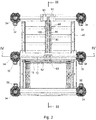
Figure 2 shows on a larger scale an underneath view of the locking mechanism and the angler's seat support shown inFigure 1 ; -
Figure 3 shows a cross-sectional view of the locking mechanism and the angler's seat support shown inFigure 1 , the plane of the cross-section being indicated by the line III-III inFigure 1 ; -
Figure 4 shows a cross-sectional view of the locking mechanism and the angler's seat support shown inFigure 1 , the plane of the cross-section being indicated by the line IV-IV inFigure 1 ; -
Figure 5 shows a perspective view corresponding to that shown inFigure 1 , with a cover fitted over the footplate; -
Figure 6 shows on a larger scale a perspective view from underneath, from the front and from the other side, of a slide component of the locking mechanism and a footplate part of the angler's seat support shown inFigure 1 , with a cover fitted over the footplate; -
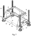
Figure 7 shows on a larger scale a perspective view from above, from the front and from the said one side of a fixed component of the locking mechanism and a main support part of the angler's seat support shown inFigure 1 ; -
Figure 8 shows on a larger scale still a perspective view from underneath, from the front and to the said one side of a slide part of the locking mechanism shown inFigure 1 ; -
Figure 9 shows on a larger scale still a perspective view from above, from the front, and to the said one side of a fixed component of the locking mechanism shown inFigure 1 ; -
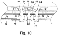
Figure 10 shows on a very much larger scale parts of what is shown in the cross-section ofFigure 4 ; and -
Figure 11 shows on a very much larger scale parts of what is shown in the cross-section ofFigure 3 . - The angler's
seat support 10 shown inFigures 1 to 11 comprises an aluminiumseat support frame 12 constituting a support part. Theframe 12 itself has two mutually parallel elongatebase channel sections 14 having respective inwardly facingchannels 16. These are fixed together at their respective rear ends by a transverserear section 18. Twocurved arm sections 20 extend upwardly from the respective front ends of thebase sections 14 and then rearwardly, horizontally and slightly towards one another. Mutually paralleltubular sections arms 20 to which they are welded, one, 21a, across the front ends of the horizontal portions of thearm sections 20, and the other, 21b, across the rear ends thereof. The rear tubular section, 21b, is further supported by astrut 24 extending upwardly from the middle of thetransverse section 18 to which it is welded to the middle of therear section 21b to which it is also welded. Slantingdecorative covers 26 are provided at opposite ends of thestrut 24, extending between thestrut 24 and theframe part 22 at the upper end of thestrut 24, and between the reartransverse section 18 and thestrut 24 at the lower end thereof. The width of thestrut 24 reinforces theframe 12 against a parallelogram collapse. -
Plastics material connectors 22 extend from respective ends of thetubular section 21a to respective ends of thetubular section 21b, and are adapted to support an angler's box (not shown) itself adapted to act as a seat for an angler as well as to contain fishing equipment. -
Clamps 28 are fixed to and extend outwardly from the front and rear ends of the twobase channel sections 14. Eachclamp 28 holds a generallyupright leg 30 by aclamp screw 32 in a releasable fashion. Thus the legs are shown in a fully retracted position, but theclamp screw 32 can be loosened to enable the leg to be moved downwardly relative to thesupport frame 12 to any selected extent, whereafter theclamp screw 32 can be tightened to hold the leg in that selected degree of extension. In this way uneven ground can be accommodated, so that the legs support thebase channel sections 14 in a horizontal condition even on uneven ground. - Respective generally planar generally
circular feet 34 are attached to the lower ends of thelegs 30 by way of ball-and-socket joints 36 so that the feet can swivel relative to theleg 30 to accommodate any slope in the ground at the base of theleg 30. Thefeet 34 are especially adapted to resist sinking of theleg 30 into the ground, which is a hazard often encountered especially if the ground is soft. - A generally
rectangular footplate 40 having two parallelhorizontal side sections 42 and a multiplicity oftransverse sections 44 connecting theside sections 40 together has itside sections 42 received slidably within thechannels 16 of thebase sections 14, so that thefootplate 40 as a whole can be extended out from and retracted back into theseat support frame 12. A fronttransverse section 46 of thefootplate 40 extends outwardly beyond theside sections 42 to provide twofurther clamps 28 withclamp screws 32 releasably securinglegs 30 withfeet 34 in the same manner and for the same purpose as theclamps 28 andlegs 30 attached to themain support 12. - As shown more clearly in
Figures 7 to 10 , a fronttransverse section 50 of theseat support frame 12 has afixed component 52 of alocking mechanism 53 attached to its underside, with moveable members in the form of twopins 54 spaced apart from one another transversely in relation to the direction of movement of thefootplate 40 relative to theseat support 12, with roundedupper ends 56 of thepins 54 protruding upwardly through thesection 50. Thepins 54 are rigidly fixed to a transversely extendingflange 57. Acam part 58 extends upwardly from the centre of theflange 57, midway between thepins 54. Thecam part 58 has a rearwardly facingedge 59 which slants at an angle of 45° relative to the horizontal. Through-holes 60 in asupport plate 62 of thecomponent 52 receive lower ends of thepins 54, and through-holes 64 through theflange 57 on opposite sides of thecam part 58 receive upper ends ofguide pegs 66 which are fixed to and extend upwardly from thesupport plate 62.Helical compression springs 68 are located between and urge apart thesupport plate 62 and theflange 57. - As can be seen readily from
Figure 10 , thesection 50 has anupper wall 70 and alower wall 72. The upper side of thesupport plate 62 of thefixed component 52 is secured to the lower surface of thelower wall 72 where there is anaperture 74 upwardly through which extend the parts of thecomponent 52 which are supported by theplate 62. Theupper wall 70 is provided with two through-holes 76 through which thepins 54 extend upwardly, and aslot 78 through which thecam part 58 extends upwardly. Theflange 57 is urged upwardly against the lower side of theupper wall 70 by thecompression springs 68. - Shown more clearly in
Figures 10 and11 is anelongate slide component 80 of thelocking mechanism 53, in the form of a runner type profile, attached to the underside of thefootplate 40. It extends centrally from the front to the back of thefootplate 40 and has twoelongate ridges 82 in which a first pair ofapertures 84 is formed towards the rear ends of theridges 82, the apertures of the pair being formed in respective ones of theridges 82 and being formed in registration with one another and spaced apart transversely of thecomponent 80. A further such pair ofapertures 86 is formed towards the forward ends of theridges 82. - A
release rod 88 is retained within theelongate slide component 80 in such a fashion as to be moveable between a rearward non-release position (as shown inFigure 11 for example) and a forward release position. Afinger grip 90 in the form of a T-bar profile on the underside of ahandle 92 of the footplate 40 at the front thereof is fixed to therelease rod 88. Acompression spring 94 is located between and urges apart anabutment 96 which is fixed relative to theridges 82 and anabutment 98 which is fixed relative to therelease rod 88, so that thecompression spring 94 urges therelease rod 88 into its non-release position. Respectiverounded cam parts 100 associated with the two pairs ofapertures cam rod 88, protruding downwardly therefrom and located thereon such that they are offset rearwardly of the apertures when therelease rod 88 is in its rearward non-release position. - The accompanying drawings show the
seat support 10 with itsfootplate 40 locked in its extended position by thelocking mechanism 53, thepins 54 of the fixedcomponent 52 of thelocking mechanism 53 being received in therear apertures 84 of theridges 82, so that thepins 54 and theridges 82 constitute interengaging portions which hold the footplate 40 against sliding relative to theseat support frame 12. - When the user wishes to retract the footplate 40 into the
seat support frame 12 for stowage or to move theseat support 10 to a different location, the user places the palm of one hand against thehandle 92 whilst inserting the fingers of the same hand behind thefinger grip 90. With a squeezing action of the hand, the user now moves therelease rod 88 against the restoring force of thecompression spring 94 into its forward release position. As a result, therearward cam part 100 engages the slantingedge 59 of thecam part 58 and urges it downwardly with further relative forward movement of therelease rod 88. This pushes theflange 57 and with it thepins 54 downwardly, so that the pins are removed from theapertures 84 and thepins 54 no longer engage theridges 82. Thefootplate 40 is now free to be pushed or retracted into thesupport frame 12 by the user pushing against thehandle 92 with the one hand used to unlock thelocking mechanism 53. Once such disengagement has occurred, the user releases thefinger grip 90 so that it and therelease rod 88 return to their rearward non-release positions. As a result, once the footplate 40 is fully retracted, thepins 54 which during the sliding action had been urged by the compression springs 68 against theridges 82, now snap into theapertures 86 under the action of those compression springs 68 to lock thefootplate 40 in the fully retracted position relative to thesupport frame 12. - A similar operation enables the user to extend the
footplate 40. Thus the user squeezes thefinger grip 90 towards thehandle 92 to operate therelease rod 88, pulls the footplate 40 out from thesupport frame 12, releasing the finger grip once thepins 54 are clear of theapertures 86, so that they will snap into theapertures 84 once the footplate 40 is in the fully extended position so that thelocking mechanism 53 locks the footplate 40 in that position. - A
cover plate 110 may be provided over thefootrest 40 to protect thelocking mechanism 53 from the ingress of dirt or angler bait when in use, as shown inFigure 5 . - It will be appreciated the in the illustrated construction there only needs to be one fixed
component 52 of thelocking mechanism 53, reducing the number of parts required and the complexity thereof. - Numerous variations and modifications to the illustrated
locking mechanism 53 and angler'sseat support 10 may occur to the reader without taking the resulting construction outside the scope of the present invention. To give one example only, a one or more further pairs of apertures may be provided in theridges 82 to enable the user to lock thefootplate 40 in one or more intermediate positions relative to thesupport frame 12 between the fully extended and fully retracted positions.
Claims (12)
- A locking mechanism comprising a fixed component (52) which is secured to a support part (12) when the mechanism is fitted for use, and a slide component (80) which when the mechanism is fitted for use is secured to a slidable part (40) which can be extended from and retracted back into such a support part (12), characterised in that the slide component (80) has an operable part (90) which when the mechanism is fitted for use is at a front portion of such a slidable part (40) which the user holds to extend and retract the slidable part (40), there being interengaging portions (54 and 82) of the fixed component (52) and the slide component (80) which interengage to hold such a slidable part (40) in position relative to such a support part (12) when the mechanism is fitted for use, and there being at least one moveable member (54 or 88) of one of the said fixed and slide components (52 and 80) moveable directly or indirectly by means of the said operable part (90) to disengage the said interengaging portions (54 and 82) thereby to enable such a slidable part (40) to be extended from or retracted into such a support part (12) when the mechanism is in use.
- A locking mechanism according to claim 1, characterised in that the said operable part (90) is sprung-loaded towards a condition in which it will not cause the interengaging portions (54 and 82) to disengage when the mechanism is in use.
- A locking mechanism according to claim 1 or claim 2, characterised in that the said at least one moveable member (54) is a member of the said fixed component (52).
- A locking mechanism according to any preceding claim, characterised in that the said at least one moveable member (54) is sprung loaded towards an engagement positon.
- A locking mechanism according to any preceding claim, characterised in that the said slide component (80) is provided with at least one aperture (84) located to receive the said moveable member (54) with a given position of such a slidable part (40) relative to such a moveable part (54), to lock those two parts in position relative to one another.
- A locking mechanism according to any preceding claim, characterised in that the said slide component (80) has a cam portion (100) connected to the operable part (90) to be moved thereby into and out of a position in which it will cause the interengaging portions (54 and 82) to disengage, or to inhibit engagement therebetween.
- A locking mechanism according to any preceding claim, characterised in that the said fixed component (52) has a moveable cam portion (58) fixed relative to the said moveable member (54), the moveable cam portion (58) being moved by the cam portion (100) of the said slide component (80) so as to move the said moveable member (54) out of engagement with the interengaging portion (82) of the slide component (80), or so as to inhibit engagement of the said moveable member (54) with the interengaging portion (82) of the slide component (80), when the said operable part (90) is operated.
- A locking mechanism according to any preceding claim, characterised in that the slide component (80) is elongate with more than one such aperture (84) spaced apart along its length, the cam portion (100) of the slide component (80) being provided with respective cams (100) for the apertures (84).
- A locking mechanism according to any preceding claim, characterised in that there is a pair of moveable members (54) each being as the said moveable member (54), receivable in one or more pairs of apertures (84, 86) each being as the said at least one aperture (84), each pair (84, 86) being spaced apart across the direction of movement of such a slideable part (40) relative to such a support part (12) when the mechanism is fitted for use.
- A support part (12) having a slidable part (40) which can be extended from and retracted into the support part (12), these two parts (12 and 40) being fitted with a locking mechanism as claimed in any preceding claim.
- A support part (12) according to claim 10, characterised in that the support part (12) is adapted to support an angler's tackle box as a seat, and the slidable part (40) constitutes a footplate.
- A support part according to claim 11, characterised in that the footplate (40) is provided with a cover (110) to protect the locking mechanism from the ingress of dirt and fish bait.
Applications Claiming Priority (1)
| Application Number | Priority Date | Filing Date | Title |
|---|---|---|---|
| GBGB1818762.5A GB201818762D0 (en) | 2018-11-16 | 2018-11-16 | A locking mechanisn |
Publications (3)
| Publication Number | Publication Date |
|---|---|
| EP3653050A1 true EP3653050A1 (en) | 2020-05-20 |
| EP3653050C0 EP3653050C0 (en) | 2024-05-15 |
| EP3653050B1 EP3653050B1 (en) | 2024-05-15 |
Family
ID=64739980
Family Applications (1)
| Application Number | Title | Priority Date | Filing Date |
|---|---|---|---|
| EP19206378.2A Active EP3653050B1 (en) | 2018-11-16 | 2019-10-30 | A locking mechanism |
Country Status (4)
| Country | Link |
|---|---|
| EP (1) | EP3653050B1 (en) |
| ES (1) | ES2985085T3 (en) |
| GB (1) | GB201818762D0 (en) |
| PL (1) | PL3653050T3 (en) |
Citations (3)
| Publication number | Priority date | Publication date | Assignee | Title |
|---|---|---|---|---|
| EP1905299A1 (en) * | 2006-09-28 | 2008-04-02 | Mossalgue | Frame for fishing seat-box |
| EP2957172A1 (en) * | 2014-06-19 | 2015-12-23 | Michele Bedin | Fishing seat box |
| CN108528292A (en) * | 2018-06-06 | 2018-09-14 | 广东乐美达集团有限公司 | The head restraint height adjusting device and automobile child seat of automobile child seat |
-
2018
- 2018-11-16 GB GBGB1818762.5A patent/GB201818762D0/en not_active Ceased
-
2019
- 2019-10-30 EP EP19206378.2A patent/EP3653050B1/en active Active
- 2019-10-30 PL PL19206378.2T patent/PL3653050T3/en unknown
- 2019-10-30 ES ES19206378T patent/ES2985085T3/en active Active
Patent Citations (3)
| Publication number | Priority date | Publication date | Assignee | Title |
|---|---|---|---|---|
| EP1905299A1 (en) * | 2006-09-28 | 2008-04-02 | Mossalgue | Frame for fishing seat-box |
| EP2957172A1 (en) * | 2014-06-19 | 2015-12-23 | Michele Bedin | Fishing seat box |
| CN108528292A (en) * | 2018-06-06 | 2018-09-14 | 广东乐美达集团有限公司 | The head restraint height adjusting device and automobile child seat of automobile child seat |
Also Published As
| Publication number | Publication date |
|---|---|
| EP3653050C0 (en) | 2024-05-15 |
| GB201818762D0 (en) | 2019-01-02 |
| EP3653050B1 (en) | 2024-05-15 |
| ES2985085T3 (en) | 2024-11-04 |
| PL3653050T3 (en) | 2024-08-19 |
Similar Documents
| Publication | Publication Date | Title |
|---|---|---|
| US11992928B2 (en) | Tool with articulated handle | |
| CN1127314C (en) | Folding table | |
| US8376461B2 (en) | Child seat convertible between a high chair configuration and a swing configuration and method of conversion thereof | |
| DE60223452T2 (en) | Vertical vacuum cleaner with vertical, removable handle | |
| US5489138A (en) | Height adjustable high chair | |
| EP2467039B1 (en) | Walking stick | |
| US6428034B1 (en) | Buggy | |
| DE29914146U1 (en) | Buggy with removable additional seat | |
| DE10021514C2 (en) | Anti-trap mechanism for a folding chair | |
| EP1375816A1 (en) | Step stool with movable handrail | |
| DE202015105635U1 (en) | Flat mop with a self-release system | |
| DE102020112393A1 (en) | Multi-seat stroller | |
| DE202018100399U1 (en) | Electric push rod and electric headrest mount | |
| KR20160079012A (en) | Tripod with fast opening and closing mechanism and methods of use | |
| US5060939A (en) | Multi-position exercise bench | |
| US8011707B1 (en) | Coupling assembly for transporting wheeled chairs and associated method | |
| DE19919244A1 (en) | Push chair (baby buggy) for folding up for carrying on shoulder, with front and rear leg insertion bodies, two support bars and two locking devices | |
| US10827761B1 (en) | Collapsible fish filleting station systems | |
| DE60030689T2 (en) | Stroller and method for folding a stroller | |
| US20210186205A1 (en) | Folding table | |
| DE68916013T2 (en) | REVERSIBLE VACUUM CLEANER. | |
| DE19939185A1 (en) | Changeable device for children | |
| EP3653050B1 (en) | A locking mechanism | |
| DE102015118621B4 (en) | Cleaning device with a pivoting handle | |
| DE20010365U1 (en) | stroller |
Legal Events
| Date | Code | Title | Description |
|---|---|---|---|
| PUAI | Public reference made under article 153(3) epc to a published international application that has entered the european phase |
Free format text: ORIGINAL CODE: 0009012 |
|
| STAA | Information on the status of an ep patent application or granted ep patent |
Free format text: STATUS: THE APPLICATION HAS BEEN PUBLISHED |
|
| AK | Designated contracting states |
Kind code of ref document: A1 Designated state(s): AL AT BE BG CH CY CZ DE DK EE ES FI FR GB GR HR HU IE IS IT LI LT LU LV MC MK MT NL NO PL PT RO RS SE SI SK SM TR |
|
| AX | Request for extension of the european patent |
Extension state: BA ME |
|
| STAA | Information on the status of an ep patent application or granted ep patent |
Free format text: STATUS: REQUEST FOR EXAMINATION WAS MADE |
|
| 17P | Request for examination filed |
Effective date: 20201120 |
|
| RBV | Designated contracting states (corrected) |
Designated state(s): AL AT BE BG CH CY CZ DE DK EE ES FI FR GB GR HR HU IE IS IT LI LT LU LV MC MK MT NL NO PL PT RO RS SE SI SK SM TR |
|
| GRAP | Despatch of communication of intention to grant a patent |
Free format text: ORIGINAL CODE: EPIDOSNIGR1 |
|
| STAA | Information on the status of an ep patent application or granted ep patent |
Free format text: STATUS: GRANT OF PATENT IS INTENDED |
|
| INTG | Intention to grant announced |
Effective date: 20231215 |
|
| GRAS | Grant fee paid |
Free format text: ORIGINAL CODE: EPIDOSNIGR3 |
|
| GRAA | (expected) grant |
Free format text: ORIGINAL CODE: 0009210 |
|
| STAA | Information on the status of an ep patent application or granted ep patent |
Free format text: STATUS: THE PATENT HAS BEEN GRANTED |
|
| AK | Designated contracting states |
Kind code of ref document: B1 Designated state(s): AL AT BE BG CH CY CZ DE DK EE ES FI FR GB GR HR HU IE IS IT LI LT LU LV MC MK MT NL NO PL PT RO RS SE SI SK SM TR |
|
| REG | Reference to a national code |
Ref country code: CH Ref legal event code: EP |
|
| REG | Reference to a national code |
Ref country code: IE Ref legal event code: FG4D |
|
| REG | Reference to a national code |
Ref country code: DE Ref legal event code: R096 Ref document number: 602019052190 Country of ref document: DE |
|
| U01 | Request for unitary effect filed |
Effective date: 20240520 |
|
| U07 | Unitary effect registered |
Designated state(s): AT BE BG DE DK EE FI FR IT LT LU LV MT NL PT SE SI Effective date: 20240529 |
|
| U1N | Appointed representative for the unitary patent procedure changed after the registration of the unitary effect |
Representative=s name: MATHYS & SQUIRE; GB |
|
| PG25 | Lapsed in a contracting state [announced via postgrant information from national office to epo] |
Ref country code: IS Free format text: LAPSE BECAUSE OF FAILURE TO SUBMIT A TRANSLATION OF THE DESCRIPTION OR TO PAY THE FEE WITHIN THE PRESCRIBED TIME-LIMIT Effective date: 20240915 |
|
| PG25 | Lapsed in a contracting state [announced via postgrant information from national office to epo] |
Ref country code: HR Free format text: LAPSE BECAUSE OF FAILURE TO SUBMIT A TRANSLATION OF THE DESCRIPTION OR TO PAY THE FEE WITHIN THE PRESCRIBED TIME-LIMIT Effective date: 20240515 |
|
| PG25 | Lapsed in a contracting state [announced via postgrant information from national office to epo] |
Ref country code: GR Free format text: LAPSE BECAUSE OF FAILURE TO SUBMIT A TRANSLATION OF THE DESCRIPTION OR TO PAY THE FEE WITHIN THE PRESCRIBED TIME-LIMIT Effective date: 20240816 |
|
| PG25 | Lapsed in a contracting state [announced via postgrant information from national office to epo] |
Ref country code: NO Free format text: LAPSE BECAUSE OF FAILURE TO SUBMIT A TRANSLATION OF THE DESCRIPTION OR TO PAY THE FEE WITHIN THE PRESCRIBED TIME-LIMIT Effective date: 20240815 Ref country code: IS Free format text: LAPSE BECAUSE OF FAILURE TO SUBMIT A TRANSLATION OF THE DESCRIPTION OR TO PAY THE FEE WITHIN THE PRESCRIBED TIME-LIMIT Effective date: 20240915 Ref country code: HR Free format text: LAPSE BECAUSE OF FAILURE TO SUBMIT A TRANSLATION OF THE DESCRIPTION OR TO PAY THE FEE WITHIN THE PRESCRIBED TIME-LIMIT Effective date: 20240515 Ref country code: GR Free format text: LAPSE BECAUSE OF FAILURE TO SUBMIT A TRANSLATION OF THE DESCRIPTION OR TO PAY THE FEE WITHIN THE PRESCRIBED TIME-LIMIT Effective date: 20240816 Ref country code: RS Free format text: LAPSE BECAUSE OF FAILURE TO SUBMIT A TRANSLATION OF THE DESCRIPTION OR TO PAY THE FEE WITHIN THE PRESCRIBED TIME-LIMIT Effective date: 20240815 |
|
| REG | Reference to a national code |
Ref country code: ES Ref legal event code: FG2A Ref document number: 2985085 Country of ref document: ES Kind code of ref document: T3 Effective date: 20241104 |
|
| U20 | Renewal fee for the european patent with unitary effect paid |
Year of fee payment: 6 Effective date: 20241017 |
|
| PG25 | Lapsed in a contracting state [announced via postgrant information from national office to epo] |
Ref country code: CZ Free format text: LAPSE BECAUSE OF FAILURE TO SUBMIT A TRANSLATION OF THE DESCRIPTION OR TO PAY THE FEE WITHIN THE PRESCRIBED TIME-LIMIT Effective date: 20240515 |
|
| PG25 | Lapsed in a contracting state [announced via postgrant information from national office to epo] |
Ref country code: SK Free format text: LAPSE BECAUSE OF FAILURE TO SUBMIT A TRANSLATION OF THE DESCRIPTION OR TO PAY THE FEE WITHIN THE PRESCRIBED TIME-LIMIT Effective date: 20240515 Ref country code: RO Free format text: LAPSE BECAUSE OF FAILURE TO SUBMIT A TRANSLATION OF THE DESCRIPTION OR TO PAY THE FEE WITHIN THE PRESCRIBED TIME-LIMIT Effective date: 20240515 |
|
| PG25 | Lapsed in a contracting state [announced via postgrant information from national office to epo] |
Ref country code: SM Free format text: LAPSE BECAUSE OF FAILURE TO SUBMIT A TRANSLATION OF THE DESCRIPTION OR TO PAY THE FEE WITHIN THE PRESCRIBED TIME-LIMIT Effective date: 20240515 |
|
| PG25 | Lapsed in a contracting state [announced via postgrant information from national office to epo] |
Ref country code: SM Free format text: LAPSE BECAUSE OF FAILURE TO SUBMIT A TRANSLATION OF THE DESCRIPTION OR TO PAY THE FEE WITHIN THE PRESCRIBED TIME-LIMIT Effective date: 20240515 Ref country code: SK Free format text: LAPSE BECAUSE OF FAILURE TO SUBMIT A TRANSLATION OF THE DESCRIPTION OR TO PAY THE FEE WITHIN THE PRESCRIBED TIME-LIMIT Effective date: 20240515 Ref country code: RO Free format text: LAPSE BECAUSE OF FAILURE TO SUBMIT A TRANSLATION OF THE DESCRIPTION OR TO PAY THE FEE WITHIN THE PRESCRIBED TIME-LIMIT Effective date: 20240515 Ref country code: CZ Free format text: LAPSE BECAUSE OF FAILURE TO SUBMIT A TRANSLATION OF THE DESCRIPTION OR TO PAY THE FEE WITHIN THE PRESCRIBED TIME-LIMIT Effective date: 20240515 |
|
| REG | Reference to a national code |
Ref country code: DE Ref legal event code: R097 Ref document number: 602019052190 Country of ref document: DE |
|
| PLBE | No opposition filed within time limit |
Free format text: ORIGINAL CODE: 0009261 |
|
| STAA | Information on the status of an ep patent application or granted ep patent |
Free format text: STATUS: NO OPPOSITION FILED WITHIN TIME LIMIT |
|
| 26N | No opposition filed |
Effective date: 20250218 |
|
| REG | Reference to a national code |
Ref country code: CH Ref legal event code: PL |
|
| PG25 | Lapsed in a contracting state [announced via postgrant information from national office to epo] |
Ref country code: MC Free format text: LAPSE BECAUSE OF FAILURE TO SUBMIT A TRANSLATION OF THE DESCRIPTION OR TO PAY THE FEE WITHIN THE PRESCRIBED TIME-LIMIT Effective date: 20240515 |
|
| PG25 | Lapsed in a contracting state [announced via postgrant information from national office to epo] |
Ref country code: CH Free format text: LAPSE BECAUSE OF NON-PAYMENT OF DUE FEES Effective date: 20241031 |
|
| PG25 | Lapsed in a contracting state [announced via postgrant information from national office to epo] |
Ref country code: IE Free format text: LAPSE BECAUSE OF NON-PAYMENT OF DUE FEES Effective date: 20241030 |
|
| U20 | Renewal fee for the european patent with unitary effect paid |
Year of fee payment: 7 Effective date: 20251015 |
|
| PGFP | Annual fee paid to national office [announced via postgrant information from national office to epo] |
Ref country code: GB Payment date: 20251016 Year of fee payment: 7 |
|
| PGFP | Annual fee paid to national office [announced via postgrant information from national office to epo] |
Ref country code: PL Payment date: 20251024 Year of fee payment: 7 |
|
| PGFP | Annual fee paid to national office [announced via postgrant information from national office to epo] |
Ref country code: ES Payment date: 20251215 Year of fee payment: 7 |
|
| PG25 | Lapsed in a contracting state [announced via postgrant information from national office to epo] |
Ref country code: HU Free format text: LAPSE BECAUSE OF FAILURE TO SUBMIT A TRANSLATION OF THE DESCRIPTION OR TO PAY THE FEE WITHIN THE PRESCRIBED TIME-LIMIT; INVALID AB INITIO Effective date: 20191030 |
|
| PG25 | Lapsed in a contracting state [announced via postgrant information from national office to epo] |
Ref country code: CY Free format text: LAPSE BECAUSE OF FAILURE TO SUBMIT A TRANSLATION OF THE DESCRIPTION OR TO PAY THE FEE WITHIN THE PRESCRIBED TIME-LIMIT; INVALID AB INITIO Effective date: 20191030 |