EP3652793B1 - Method for determining battery pack temperature and state of charge - Google Patents
Method for determining battery pack temperature and state of charge Download PDFInfo
- Publication number
- EP3652793B1 EP3652793B1 EP18749226.9A EP18749226A EP3652793B1 EP 3652793 B1 EP3652793 B1 EP 3652793B1 EP 18749226 A EP18749226 A EP 18749226A EP 3652793 B1 EP3652793 B1 EP 3652793B1
- Authority
- EP
- European Patent Office
- Prior art keywords
- value
- battery
- criteria
- charge
- state
- Prior art date
- Legal status (The legal status is an assumption and is not a legal conclusion. Google has not performed a legal analysis and makes no representation as to the accuracy of the status listed.)
- Active
Links
Images








Classifications
-
- B—PERFORMING OPERATIONS; TRANSPORTING
- B60—VEHICLES IN GENERAL
- B60L—PROPULSION OF ELECTRICALLY-PROPELLED VEHICLES; SUPPLYING ELECTRIC POWER FOR AUXILIARY EQUIPMENT OF ELECTRICALLY-PROPELLED VEHICLES; ELECTRODYNAMIC BRAKE SYSTEMS FOR VEHICLES IN GENERAL; MAGNETIC SUSPENSION OR LEVITATION FOR VEHICLES; MONITORING OPERATING VARIABLES OF ELECTRICALLY-PROPELLED VEHICLES; ELECTRIC SAFETY DEVICES FOR ELECTRICALLY-PROPELLED VEHICLES
- B60L58/00—Methods or circuit arrangements for monitoring or controlling batteries or fuel cells, specially adapted for electric vehicles
- B60L58/10—Methods or circuit arrangements for monitoring or controlling batteries or fuel cells, specially adapted for electric vehicles for monitoring or controlling batteries
- B60L58/12—Methods or circuit arrangements for monitoring or controlling batteries or fuel cells, specially adapted for electric vehicles for monitoring or controlling batteries responding to state of charge [SoC]
-
- H—ELECTRICITY
- H01—ELECTRIC ELEMENTS
- H01M—PROCESSES OR MEANS, e.g. BATTERIES, FOR THE DIRECT CONVERSION OF CHEMICAL ENERGY INTO ELECTRICAL ENERGY
- H01M10/00—Secondary cells; Manufacture thereof
- H01M10/42—Methods or arrangements for servicing or maintenance of secondary cells or secondary half-cells
- H01M10/48—Accumulators combined with arrangements for measuring, testing or indicating the condition of cells, e.g. the level or density of the electrolyte
- H01M10/482—Accumulators combined with arrangements for measuring, testing or indicating the condition of cells, e.g. the level or density of the electrolyte for several batteries or cells simultaneously or sequentially
-
- H—ELECTRICITY
- H01—ELECTRIC ELEMENTS
- H01M—PROCESSES OR MEANS, e.g. BATTERIES, FOR THE DIRECT CONVERSION OF CHEMICAL ENERGY INTO ELECTRICAL ENERGY
- H01M50/00—Constructional details or processes of manufacture of the non-active parts of electrochemical cells other than fuel cells, e.g. hybrid cells
- H01M50/20—Mountings; Secondary casings or frames; Racks, modules or packs; Suspension devices; Shock absorbers; Transport or carrying devices; Holders
- H01M50/204—Racks, modules or packs for multiple batteries or multiple cells
-
- B—PERFORMING OPERATIONS; TRANSPORTING
- B60—VEHICLES IN GENERAL
- B60L—PROPULSION OF ELECTRICALLY-PROPELLED VEHICLES; SUPPLYING ELECTRIC POWER FOR AUXILIARY EQUIPMENT OF ELECTRICALLY-PROPELLED VEHICLES; ELECTRODYNAMIC BRAKE SYSTEMS FOR VEHICLES IN GENERAL; MAGNETIC SUSPENSION OR LEVITATION FOR VEHICLES; MONITORING OPERATING VARIABLES OF ELECTRICALLY-PROPELLED VEHICLES; ELECTRIC SAFETY DEVICES FOR ELECTRICALLY-PROPELLED VEHICLES
- B60L50/00—Electric propulsion with power supplied within the vehicle
- B60L50/50—Electric propulsion with power supplied within the vehicle using propulsion power supplied by batteries or fuel cells
- B60L50/60—Electric propulsion with power supplied within the vehicle using propulsion power supplied by batteries or fuel cells using power supplied by batteries
- B60L50/64—Constructional details of batteries specially adapted for electric vehicles
-
- B—PERFORMING OPERATIONS; TRANSPORTING
- B60—VEHICLES IN GENERAL
- B60L—PROPULSION OF ELECTRICALLY-PROPELLED VEHICLES; SUPPLYING ELECTRIC POWER FOR AUXILIARY EQUIPMENT OF ELECTRICALLY-PROPELLED VEHICLES; ELECTRODYNAMIC BRAKE SYSTEMS FOR VEHICLES IN GENERAL; MAGNETIC SUSPENSION OR LEVITATION FOR VEHICLES; MONITORING OPERATING VARIABLES OF ELECTRICALLY-PROPELLED VEHICLES; ELECTRIC SAFETY DEVICES FOR ELECTRICALLY-PROPELLED VEHICLES
- B60L50/00—Electric propulsion with power supplied within the vehicle
- B60L50/50—Electric propulsion with power supplied within the vehicle using propulsion power supplied by batteries or fuel cells
- B60L50/60—Electric propulsion with power supplied within the vehicle using propulsion power supplied by batteries or fuel cells using power supplied by batteries
- B60L50/66—Arrangements of batteries
-
- H—ELECTRICITY
- H01—ELECTRIC ELEMENTS
- H01M—PROCESSES OR MEANS, e.g. BATTERIES, FOR THE DIRECT CONVERSION OF CHEMICAL ENERGY INTO ELECTRICAL ENERGY
- H01M10/00—Secondary cells; Manufacture thereof
- H01M10/42—Methods or arrangements for servicing or maintenance of secondary cells or secondary half-cells
- H01M10/425—Structural combination with electronic components, e.g. electronic circuits integrated to the outside of the casing
-
- H—ELECTRICITY
- H01—ELECTRIC ELEMENTS
- H01M—PROCESSES OR MEANS, e.g. BATTERIES, FOR THE DIRECT CONVERSION OF CHEMICAL ENERGY INTO ELECTRICAL ENERGY
- H01M10/00—Secondary cells; Manufacture thereof
- H01M10/42—Methods or arrangements for servicing or maintenance of secondary cells or secondary half-cells
- H01M10/48—Accumulators combined with arrangements for measuring, testing or indicating the condition of cells, e.g. the level or density of the electrolyte
- H01M10/486—Accumulators combined with arrangements for measuring, testing or indicating the condition of cells, e.g. the level or density of the electrolyte for measuring temperature
-
- H—ELECTRICITY
- H01—ELECTRIC ELEMENTS
- H01M—PROCESSES OR MEANS, e.g. BATTERIES, FOR THE DIRECT CONVERSION OF CHEMICAL ENERGY INTO ELECTRICAL ENERGY
- H01M50/00—Constructional details or processes of manufacture of the non-active parts of electrochemical cells other than fuel cells, e.g. hybrid cells
- H01M50/20—Mountings; Secondary casings or frames; Racks, modules or packs; Suspension devices; Shock absorbers; Transport or carrying devices; Holders
- H01M50/249—Mountings; Secondary casings or frames; Racks, modules or packs; Suspension devices; Shock absorbers; Transport or carrying devices; Holders specially adapted for aircraft or vehicles, e.g. cars or trains
-
- B—PERFORMING OPERATIONS; TRANSPORTING
- B60—VEHICLES IN GENERAL
- B60L—PROPULSION OF ELECTRICALLY-PROPELLED VEHICLES; SUPPLYING ELECTRIC POWER FOR AUXILIARY EQUIPMENT OF ELECTRICALLY-PROPELLED VEHICLES; ELECTRODYNAMIC BRAKE SYSTEMS FOR VEHICLES IN GENERAL; MAGNETIC SUSPENSION OR LEVITATION FOR VEHICLES; MONITORING OPERATING VARIABLES OF ELECTRICALLY-PROPELLED VEHICLES; ELECTRIC SAFETY DEVICES FOR ELECTRICALLY-PROPELLED VEHICLES
- B60L2240/00—Control parameters of input or output; Target parameters
- B60L2240/40—Drive Train control parameters
- B60L2240/54—Drive Train control parameters related to batteries
- B60L2240/545—Temperature
-
- H—ELECTRICITY
- H01—ELECTRIC ELEMENTS
- H01M—PROCESSES OR MEANS, e.g. BATTERIES, FOR THE DIRECT CONVERSION OF CHEMICAL ENERGY INTO ELECTRICAL ENERGY
- H01M10/00—Secondary cells; Manufacture thereof
- H01M10/42—Methods or arrangements for servicing or maintenance of secondary cells or secondary half-cells
- H01M10/425—Structural combination with electronic components, e.g. electronic circuits integrated to the outside of the casing
- H01M2010/4271—Battery management systems including electronic circuits, e.g. control of current or voltage to keep battery in healthy state, cell balancing
-
- H—ELECTRICITY
- H01—ELECTRIC ELEMENTS
- H01M—PROCESSES OR MEANS, e.g. BATTERIES, FOR THE DIRECT CONVERSION OF CHEMICAL ENERGY INTO ELECTRICAL ENERGY
- H01M2220/00—Batteries for particular applications
- H01M2220/20—Batteries in motive systems, e.g. vehicle, ship, plane
-
- Y—GENERAL TAGGING OF NEW TECHNOLOGICAL DEVELOPMENTS; GENERAL TAGGING OF CROSS-SECTIONAL TECHNOLOGIES SPANNING OVER SEVERAL SECTIONS OF THE IPC; TECHNICAL SUBJECTS COVERED BY FORMER USPC CROSS-REFERENCE ART COLLECTIONS [XRACs] AND DIGESTS
- Y02—TECHNOLOGIES OR APPLICATIONS FOR MITIGATION OR ADAPTATION AGAINST CLIMATE CHANGE
- Y02E—REDUCTION OF GREENHOUSE GAS [GHG] EMISSIONS, RELATED TO ENERGY GENERATION, TRANSMISSION OR DISTRIBUTION
- Y02E60/00—Enabling technologies; Technologies with a potential or indirect contribution to GHG emissions mitigation
- Y02E60/10—Energy storage using batteries
Definitions
- Safe battery performance may require battery monitoring.
- battery monitoring may include measuring battery temperature and state of charge (SOC). Based on these readings, vehicle systems may provide information on battery state.
- SOC state of charge
- the determined overall state of charge may be understood as a reported state of charge- i.e. what is reported to the vehicle.
- the determined overall temperature may be understood as the reported temperature.
- One known method determines the state of charge based on average temperature and cell state of charge. When maximum cell temperature or maximum state of charge is approaching the maximum limits, while the cell average temperature and state of charge is still below the high threshold, the reported battery temperature or state of charge (i.e. determined overall temperature or state of charge) is significantly lower than the maximum cell temperature or state of charge which can mislead or confuse users. The same may also be true for low temperature.
- the document US 2015/0318724 A1 relates to a battery system including a housing and a plurality of battery cells disposed in the housing.
- the battery system also includes a battery management system and configured to monitor one or more operational parameters of the battery system.
- the present invention relates to a battery system according to independent claim 1, wherein further developments of the inventive battery system are provided in the sub-claims 2 to 6.
- the proposed system and method are directed towards remedying such known deficiencies and addressing such needs. Therefore, the proposed system and method obtains a number of cell temperature readings and determines a single battery pack temperature for output. In addition, the proposed system and method obtains a number of individual cell state of charge (SOC) readings, determining and outputting a single battery pack state of charge.
- SOC state of charge
- the proposed system and method may evaluate a number of factors (including but not limited to maximum cell temperature, minimum cell temperature, and the like) in the individual cell temperature readings as well as vehicle parameters in order to overcome the issues described. In addition, the proposed system and method may evaluate a number of factors in the individual cell SOC readings (including but not limited to maximum cell SOC, minimum cell SOC, and the like) as well as vehicle parameters in order to overcome the issues described.
- the proposed method may identify thermal management fault and system imbalance faults by comparing the spread of cell temperature and within the battery pack and ensuring the calculated battery pack temperature (reported temperature) represents the battery pack performance limits at extreme situations, thereby improving the algorithm robustness.
- the proposed method improves algorithm robustness by identifying SOC management fault and system imbalance faults by comparing the spread of cell SOC and within the battery pack and ensuring the calculated battery pack SOC (reported SOC) represents the battery pack performance limits at extreme situations. For example, in the high end of the operating temperature, the battery pack performance is limited by maximum cell temperature. In the low end of the operating temperature region, the battery pack performance is limited by minimum cell temperature. Similarly, in the high end of the operating SOC, the battery pack performance is limited by maximum cell SOC. In the low end of the operating SOC region, the battery pack performance is limited by minimum cell SOC.
- the method disclosed herein may provide battery pack users one battery pack temperature for a battery pack (which includes multiple cells, for example but not limited to six cells)) instead of individual temperature readings or min, max, and average temperature as control inputs. Also advantageously, the method disclosed herein may provide battery pack users one battery pack SOC for a battery pack instead of individual SOC readings or min, max, and average SOC as control inputs. Additionally, charge and discharge capabilities may also be provided, as well as the remaining amount of discharge, among other features.
- a battery system comprising a battery pack having a plurality of cells, each of the plurality of cells each having a cell temperature; a battery management system coupled to the battery pack and designed to obtain a plurality of temperatures from the battery pack and output a single battery temperature, the battery management system including: a high temperature threshold value; a low temperature threshold value; and a drop value; wherein the battery management system is further configured to: if a first criteria is satisfied, assign a high value to the battery temperature; if the second criteria is satisfied but not the first criteria, assign a mid-high value to the battery temperature; if the third criteria is satisfied but not the first or second criteria, assign an average of the obtained cell temperatures to the battery temperature; if the fourth criteria is satisfied but not the first, second, or third criteria, assign a mid-low value to the battery temperature; if the fifth criteria is satisfied but not the first, second, third, or fourth criteria, assign a low value to the battery temperature; and output a single battery pack temperature value.
- the battery management system is further configured to use the cell temperature and threshold values to determine if there is a battery fault or error. Further disclosed is a system wherein the battery management system is further configured to assign a minimum value to the battery temperature when none of the criteria are fulfilled. Further disclosed is a system wherein the battery management system is further configured to assign an average value to the battery temperature when none of the criteria are fulfilled. Further disclosed is a system wherein the battery system is configured to obtain a plurality of state of charge values from the plurality of batteries. Further disclosed is a system wherein the battery management system is further configured to evaluate the plurality of state of charge values against certain criteria. Further disclosed is a system wherein the battery management system outputs a single state of charge for the battery. Further disclosed is a method of determining battery pack temperature using the system.
- the system comprises a battery management system coupled to the battery pack and designed to obtain each of the cell state of charge from the plurality of cells, the battery management system including: a high state of charge threshold value; a low state of charge threshold value; a drop value; wherein the battery management system is further configured to: if a first criteria is satisfied, assign a high value to the battery state of charge; if the second criteria is satisfied but not the first criteria, assign a mid-high value to the battery state of charge; if the third criteria is satisfied but not the first or second criteria, assign an average of the obtained cell temperatures to the battery state of charge; if the fourth criteria is satisfied but not the first, second, or third criteria, assign a mid-low value to the battery state of charge; if the fifth criteria is satisfied but not the first, second, third, or fourth criteria, assign a low value to the battery temperature; and output a single battery pack state of charge value. Further disclosed is a system wherein the battery management system is further configured to: if a first criteria is satisfied, assign a high value
- the method comprises: assigning a plurality of temperature threshold variables; obtaining a plurality of temperature readings from each of a plurality of cells; evaluating the plurality of temperature readings against a plurality of criteria, including: determining if a first criteria is satisfied and, if so, assigning a high value to the battery temperature; determining if a second criteria is satisfied but not the first criteria, and if so, assigning a mid-high value to the battery temperature; determining if a third criteria is satisfied but not the first or second criteria, and if so, assigning an average of the obtained cell temperatures to the battery temperature; determining if the fourth criteria is satisfied but not the first, second, or third criteria, and, if so, assigning a mid-low value to the battery temperature; determining if the fifth criteria is satisfied but not the first, second, third, or fourth criteria, and, if so, assigning a low value to the battery temperature; and outputting a
- a method comprising: assigning a plurality of state of charge threshold variables; obtaining a plurality of state of charge readings from each of a plurality of cells; evaluating the plurality of state of charge readings against a plurality of criteria; and outputting a single battery pack state of charge to a vehicle system.
- evaluating the plurality of state of charge readings against a plurality of criteria further comprises: determining if a first criteria is satisfied and, if so, assigning a high value to the battery state of charge; determining if a second criteria is satisfied but not the first criteria, and if so, assigning a mid-high value to the battery state of charge; determining if a third criteria is satisfied but not the first or second criteria, and if so, assigning an average of the obtained cell temperatures to the battery state of charge; determining if the fourth criteria is satisfied but not the first, second, or third criteria, and, if so, assigning a mid-low value to the battery state of charge.
- a vehicle performing the methods disclosed herein. Further disclosed is a vehicle having the systems described herein.
- FIG. 1 a cutaway view of a vehicle 103 is shown.
- the vehicle 103 is shown having a battery system 101 which is comprised of a plurality of battery cells 102.
- the battery cells 102 may be understood to comprise a battery pack or system 101 which then provides power to the vehicle 103 to support vehicle functionality.
- FIG. 2 shows a view of a vehicle control system, which may include again, a battery system 101 but also a battery management system (BMS) 105.
- the battery management system or BMS 105 is in communication with the battery system 101 and the vehicle 103 and its related electrical systems. This may allow, in various embodiments, for measurement of battery attributes and reporting thereof to the vehicle 103.
- the battery system 101 may further comprise a plurality of sensors 104 for obtaining temperature and/or state ⁇ tf charge information about the battery.
- the battery management system 103 may include a processor for analyzing the temperature and/or state of charge information about the battery 101.
- a temperature sensor and SOC sensor (generally, sensors 104) may be provided for each battery cell 102, in various embodiments.
- a temperature sensor may be provided, for example, in the battery system 101 for a group of battery cells 102 such that the number of temperature sensors is less than the number of cells.
- a plurality of temperature sensors may be provided in the battery 101 to obtain a plurality of temperature readings.
- the temperature readings may be obtained by the sensors essentially simultaneously.
- a plurality of SOC sensors may be provided for more than one battery cell 102 such that the number of SOC sensors is less than the number of cells, in various embodiments.
- a plurality of SOC sensors may be provided in the battery 101 to obtain a plurality of SOC readings.
- the SOC readings may be obtained essentially simultaneously.
- these requirements may impact battery management systems features. For example, these requirements may include likely fault conditions and/or operational requirements (e.g. battery temperature may need to change smoothly for interaction with the vehicle).
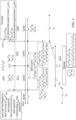
- FIG. 3 shows a first method for measurement of a battery temperature 200, according to various embodiments.
- the method 200 may take in temperature readings (for example, from a plurality of sensors 104 provided in a battery pack 101) from each cell 102 (for example, each of six cells) or less than each cell 102 and, in various embodiments, output a single temperature value for the battery pack 101.
- threshold values for battery temperature measurements are defined. These values may include a high temperature threshold (in various embodiments noted as Thigh), a low temperature threshold (in various embodiments noted as Tlow), a temperature drop (in various embodiments noted as Tdrop), and a temperature gap (in various embodiments noted as Tgap).
- Thigh may be understood as a high temperature threshold.
- the high temperature threshold may be set to the temperature value above which the system performance (for example, power or current limits) begin to decrease significantly.
- the range may be -40C to 85C.
- the low temperature threshold, Tlow may be understood as the low temperature below which the system performance (e.g. power or current limits) start to decrease significantly.
- the range of temperatures for Tlow ranges from -40C to 85C.
- Tspread may be understood as a maximum difference in temperature between the lowest cell temperature and highest cell temperature. If the difference between maximum cell temperature and average cell temperature is higher than this value, a fault may be given or set to indicate a problem with the battery thermal management system (e.g. thermal management fault, for example, based on a cell temperature sensor such as maximum cell temperature sensor). If the difference between minimum cell temperature and average cell temperature is higher than this value, a fault may be set to indicate a problem with the thermal management system based on minimum cell temperature sensor.
- Tspread may be assigned as the maximum possible delta (difference in) temperature between the cells estimated by system thermal modeling (e.g. for the vehicle) for a poor operating situation. In various embodiments, Tspread has a range of -40C to 85C. As a non-limiting example, Tspread may particularly be 10C.
- Tdrop may be understood as the minimum delta of cell maximum temperature below high temperature threshold, where the blended temperature needs to shift towards the maximum cell temperature value.
- Tdelta or Tgap should be greater than or equal to Tdrop.
- the Tdelta or Tgap value may be used to select the blended temperature calculation algorithm and may have a value in the range of -40C to 85C.
- a number of other variables may be assigned based on actual measurements obtained regarding each battery cell temperature in step S203 of FIG. 3 .
- the system may process the values in order to assign certain variable values.
- the maximum cell temperature, Tmax may be determined by the maximum obtained cell temperature of the plurality of cells.
- the minimum cell temperature, Tmin may be understood as the minimum obtained cell temperature of the plurality of cells.
- An average temperature, Tavg may be determined by averaging all obtained cell temperature readings. Given these base values, the following values may also be defined or assigned by the system, in various embodiments:
- the system may check for one or more faults or errors. These may include the checks outlined above (such as the difference between the highest and lowest reading exceeding Tspread), as well as where Tavg-Tmin>Tspread and Tmax-Tavg>Tspread.
- a fault may allow for indication of a particular or many issues with the system. For example, if maximum cell temperature is higher than average (Tavg) cell temperature for more than a calibratible amount or if minimum cell temperature is lower than average (Tavg) cell temperature for more than a calibratible amount, the likely faults can be: a cell temperature sensor in range fault, the cell temperature sensor loss of contact to cells, and coolant air flow blockage or localized heating.
- the system may assign a maximum to the battery pack temperature. In other words, the system may determine if cell temperature exceeds a threshold. In that case, if the cell temperature with the highest reading, Tmax, exceeds or equals Thigh, the battery pack temperature, Tbatt, will be assigned the value of Tmax.
- a mid-high (i.e. middle-high) value may be assigned as the battery pack temperature, for example, if the criteria of step S205 is not fulfilled.
- the system may use the evaluation process outlined in step S207 of FIGS 4 and 5 .
- the overall temperature of the battery, Tbatt may be assigned the following value: Tavg *(Tmin-Tlow)/(Tlowmid-Tlow) + Tmin*(Tlowmid-Tmin)/(Tlowmid-Tlow).
- the system may use the evaluation processes outlined in step S211 of FIGS 4 and 5 .
- calibratible value of Tdelta e.g. default, for example, 3° C
- FIGS 4 and 5A show detailed views of alternative methods for battery temperature calculation. This view shows a more detailed relationship between the assigned values and the ultimate output, Tbatt or fault. As can be seen, steps S205-S213 proceed from evaluating a higher temperature to lower. While the "steps" are presented in a certain order, it should be understood that re-ordering these steps is within the scope of this disclosure.
- FIG. 4 shows a method which may assist in producing the battery temperature value.
- variables are again defined, which may include but are not limited to the variables defined in connection with FIG. 3 .
- temperature values may be obtained from each cell in the battery pack. For example, a battery pack may have six cells and temperature values may be taken from each.
- fault handling may be evaluated. For example, if Tavg-Tmin exceeds Tspread, the battery/module may be set as invalid/module thermal management fault based on the Tmin sensor. Similarly, if Tmax-Tavg exceeds Tspread, the battery/module may be set as invalid/module thermal management fault based on the Tmax sensor, in various embodiments.
- System thermal management faults may be caused by a number of factors, including 1. Module T sensor in range fault (Tmax and Tmin thermal management fault), 2. Module T sensor lost contact to cells (Tmin thermal management fault), 3. Coolant/air flow blockage (Tmax thermal management fault).
- a maximum value is again assigned to the battery pack value where Tmax is greater than or equal to Thigh.
- a minimum value is again assigned to the battery pack value where Tmin is less than or equal to Tlow.
- the reported temperature of the battery pack will be set to the following: Tavg*(Thigh-Tmax)/(Thigh-Thighmid)+Tmax*(Tmax-Thighmid)/(Thigh-Thighmid). This may be understood as a mid-high battery temperature value.
- the reported temperature of the battery pack will be set to the following: Tavg*(Tmin-Tlow)/(Tlowmid-Tlow)+Tmin*(Tlowmid-Tmin)/(Tlowmid-Tlow). This may be understood as a mid-low battery temperature value.
- S209 may, in various embodiments, allow for the assignment of the reported value of the battery to be Tavg where the cell temperature values do reflect a battery pack temperature of Tavg.
- S207, S209, S211, and S213 may all reflect fulfillment of an assumption where (Thigh-Thighmid) exceeds Tdelta and (Tlowmid-Tlow) exceeds Tdelta.
- Tmax exceeds or is equal to (Thigh-Tdrop) and Tmax is less than Thigh, then reported battery temperature is assigned to Tmin*(Thigh-Tmax)/Tdrop + Tmax*(Tdrop-(Thigh-Tmax))/Tdrop. Otherwise, Tbatt may be assigned to Tmin, in various embodiments.
- FIG. 5A shows another method which may assist in producing the battery temperature value.
- the system may evaluate if Thighdrop is less than Tmax and Thigh, then Tbatt may be assigned the value of Tavg*(Thigh-Tmax)/(Thigh-Thighdrop)+Tmax*(Tmax-Thighdrop)/(Thigh-Thighdrop).
- This value may comprise a mid-high temperature.
- Tmin is greater than or equal to Tlowdrop and Tmax is less than or equal to Thighdrop
- the battery temperature is set to Tavg.
- a mid-low value is assigned.
- Step S207, S209, and S211 may all be assumed to fulfill the criteria of (Thighdrop-Tlowdrop)>0.
- Tbatt the battery temperature
- the system and method herein may be a "blended" method of assigning a value to the battery temperature. This may allow for advantages in interaction with vehicle systems, among others.
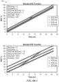
- FIGS. 5B-1 , 5B-2 and 5B-3 show a number of graphs of battery temperature, displaying example data relative to battery pack temperature measurement. The graphs may use, in various embodiments, the values described in association with the description of FIG. 3 .
- the disclosed system and method in various embodiments may allow for flexibility and functionality across a range of measurements. In various embodiments, the disclosed system and method may allow for improved compliance with vehicle requirements.
- the disclosed system and method herein may also provide for a battery state of charge calculation.
- state of charge may be measured at each cell: therefore, the system may require a single value reflecting the overall battery state of charge.
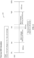
- FIG. 6 shows a summarized example of a battery state of charge method.
- the relative state of charge may impact how the cell-level state of charge measurements are handled.
- the method of pack state of charge (overall battery state of charge) may allow for a state of charge value as a proper base for charge or discharge pulse capability assessment.
- the method of determining pack state of charge may reflect the remaining amount of discharge ampere hours to a cutoff voltage.
- the state of charge minimum value (or minimum of cell SOC values) may be considered.
- the system may use a "blended" approach, such that while max, min, and average values may be provided, blends between SOCavg and SOCmax (mid-high), as well as SOCavg and SOCmin (mid-low) may also be provided.
- step S301 a method for determining overall battery SOC is shown.
- variables or calibration values are defined. These may include:
- step S303 measurements of the cell SOC (in other words, measurement of SOC from each cell) is obtained, and further variables are defined.
- SOCmax a maximum measured SOC
- SOCmin may be understood as the minimum obtained SOC of the plurality of cells.
- An average SOC, SOCavg may be determined by averaging all obtained cell state of charge readings. Given these base values, the following values may also be defined or assigned by the system, in various embodiments:
- An example logic for assigning the battery SOC is as follows:
- This step, S305 may assign the battery SOC to SOC maximum where the SOCmax is greater than or equal to SOChigh.
- This step, S307 establishes a mid-high or mid-high value for SOCbatt where the SOCmax is greater than SOChighdrop and SOCmax is less than SOChigh.
- This step, S309 assigns an average SOC to SOC battery where the SOCmin (SOC minimum) is greater than or equal to SOClowdrop and SOCmax is less than or equal to SOChighdrop.
- This step, S311, assigns a mid-low value to SOC battery where the SOCmin is greater than SOClow and SOCmin is less than SOClowdrop.
- S315 assigns a modified minimum to SOC battery (SOCbatt). 13.
- SOCbatt SOCmin;
- step S313 the battery is assigned to a minimum.
- SOCmin may be assigned as a default when other criteria do not apply.
- FIG. 8A shows another method for calculating battery state of charge, according to various embodiments.
- the steps of FIG 7 are likewise shown with accompanying calculations and values.
- the assigned battery temperature can be seen from left (e.g. S313) to right (e.g. S305) proceeding from low to high.
- S305, S307, S309, S311, S313 and S315 may be understood as criteria in the alternative, that is, the criteria may be evaluated and assigned exclusively.
- SOChigh may be 50-70%
- SOC low may be 30-50%
- SOC drop may be 5-15%
- SOC delta may be 5-15%.
- a number of variables may be defined, for example in S301, including:
- Steps S307, S309, S311, and S313 may require SOChighgap to be greater than SOCdelta and SOClowgap>SOCdelta.
- SOCbatt battery SOC output to vehicle
- SOCbatt battery SOC output to vehicle
- SOCbatt battery SOC output to vehicle
- S309 there may be a point of S309 where battery cell output is such that SOCbatt is assigned to SOCavg (an average SOC battery value). For example, this may be true where if there is a condition falling between S3 07 and S311.
- SOCbatt battery SOC output to vehicle
- FIGS. 8B-1 and 8B-2 a number of graphs using the system and method herein, particularly implementing FIG. 8A , to achieve blended SOC measurements are shown. These system and methods herein and reflect advantages of the disclosed system and method, particularly in offering flexibility to determine how the battery SOC (blended SOC) may be calculated.
- FIG. 9A shows another method for calculating battery state of charge, according to various embodiments.
- the steps of FIG. 7 are likewise shown with accompanying calculations and values.
- the assigned battery temperature can be seen from left (e.g. S313) to right (e.g. S305) proceeding from low to high. Exceptions to these ranges are located at the bottom of the page ("otherwise") and may be referenced as S315.
- the system may assign the battery SOC to SOC maximum where SOCmax is greater than or equal to SOChigh.
- Steps S307, S309, and S311 assume that SOChighdrop-SOClowdrop exceeds or is greater than zero. It should likewise be understood that S305, S307, S309, S311, S313 and S315 may be understood as criteria in the alternative, that is, the criteria may be evaluated and assigned exclusively.
- a mid-high SOC battery value may be assigned if SOChighdrop is less than SOCmax and is less than SOChigh. Then, SOCbatt is assigned the value of SOCavg * (SOChigh-SOCmax)/(SOChigh-SOChighdrop)+SOCmax*(SOCmax-SOChighdrop)/SOChigh-SOChighdrop).
- an average SOC battery value may be assigned if the SOCmin is greater than or equal to SOClowdrop and SOCmax is less than or equal to SOChighdrop. In that case, SOCbattery may be assigned to SOCaverage.
- a low mid SOC battery value may be assigned.
- SOCbatt may be assigned the value of: SOCavg*(SOCmin-SOClow)/SOClowdrop-SOClow)+SOCmin*(SOClowdrop-SOCmin)/(SOClowdrop-SOClow).
- SOCbatt may be assigned to SOCmin.
- SOCbatt may be assigned the value of SOCmin*(SOChigh-SOCmax)/(SOChigh-SOClowdrop)+SOCmax*(SOCmax-SOClowdrop)/(SOChigh-SOClowdrop). If this criteria is likewise unfulfilled, then SOCbatt may be assigned to SOCmin.
- step S3 04 fault conditions are checked. Faults may occur for a number of reasons and have a number of identifying attributes. For example, as shown in FIG. 8 , there may be a number of causes for a system imbalancing fault. These may include a balancing circuit fault, a cell self-discharge issue, or vehicle operation may not allow for sufficient balancing.
- a cell imbalance fault may be identified, for example, in step S304. For example, if (SOCavg-SOCmin) is greater than or exceeds SOCspread, an invalid/module cell imbalance fault based on SOCmin may be identified.
- an invalid/module cell imbalance fault based on SOCmax may be identified.
- a system imbalance fault may be identified if the maximum cell SOC is higher than mean cell SOC for more than a calibratible amount or if minimum cell SOC is lower than mean cell SOC for more than a calibratible amount.
- FIGS. 9B-1 and 9B-2 a number of graphs using the system and method herein, particularly implementing FIG. 9A , to achieve blended SOC measurements are shown. These graphs use the system and methods herein and reflect advantages of the disclosed system and method, particularly in offering flexibility to determine how the battery SOC (blended SOC) may be calculated.
- a system and method for determining battery pack temperature and SOC is provided.
- a plurality of temperature readings may be obtained using, for example, temperature sensors provided within a battery system. These readings may be provided to a battery management system, in various embodiments.
- the battery management system may include a processor which may process the readings using the system and method herein.
- a single, for example, blended temperature value may be output to the vehicle by the battery management system. This value may overcome disadvantages of previous systems and methods, for example by providing an improved calculation of overall battery temperature.
- SOC state of charge
- the battery management system may include a processor which may process the readings using the system and method herein.
- a single, for example, blended SOC value may be output to the vehicle by the battery management system. This value may overcome disadvantages of previous systems and methods, for example by providing an improved calculation of overall battery SOC.
- the term “coupled” means the joining of two members directly or indirectly to one another. Such joining may be stationary in nature or moveable in nature. Such joining may be achieved with the two members or the two members and any additional intermediate members being integrally formed as a single unitary body with one another or with the two members or the two members and any additional intermediate members being attached to one another. Such joining may be permanent in nature or may be removable or releasable in nature.
- elements shown as integrally formed may be constructed of multiple parts or elements show as multiple parts may be integrally formed, the operation of the interfaces may be reversed or otherwise varied, the length or width of the structures and/or members or connector or other elements of the system may be varied, the nature or number of adjustment positions provided between the elements may be varied (e.g. by variations in the number of engagement slots or size of the engagement slots or type of engagement).
- the order or sequence of any process or method steps may be varied or re-sequenced according to alternative embodiments.
- Other substitutions, modifications, changes and omissions may be made in the design, operating conditions and arrangement of the various examples of embodiments.
- the system may also include computer-readable media which may include any computer- readable media or medium that may be used to carry or store desired program code that may be accessed by a computer.
- the invention can also be embodied as computer-readable code on a computer-readable medium.
- the computer-readable medium may be any data storage device that can store data.
- the software system described herein may include a mixture of different source codes.
- the system or method herein may be operated by computer-executable instructions, such as but not limited to, program modules, executable on a computer.
- program modules include, but are not limited to, routines, programs, objects, components, data structures, and the like which perform particular tasks or implement particular instructions.
- the software system may also be operable for supporting the transfer of information within a network.
- the technical effects and technical problems in the specification are exemplary and are not limiting. It should be noted that the embodiments described in the specification may have other technical effects and can solve other technical problems. Aspects of the method described herein are implemented on a software system running on a computer system. To this end, the methods and system may be implemented in, or in association with, a general-purpose software package or a specific purpose software package. As a specific, non-limiting example, the device could be a battery management system in communication with a battery vehicle.
Landscapes
- Engineering & Computer Science (AREA)
- Chemical & Material Sciences (AREA)
- Chemical Kinetics & Catalysis (AREA)
- Electrochemistry (AREA)
- General Chemical & Material Sciences (AREA)
- Manufacturing & Machinery (AREA)
- Sustainable Energy (AREA)
- Sustainable Development (AREA)
- Life Sciences & Earth Sciences (AREA)
- Power Engineering (AREA)
- Transportation (AREA)
- Mechanical Engineering (AREA)
- Microelectronics & Electronic Packaging (AREA)
- Aviation & Aerospace Engineering (AREA)
- Secondary Cells (AREA)
- Electric Propulsion And Braking For Vehicles (AREA)
- Charge And Discharge Circuits For Batteries Or The Like (AREA)
Description
- This application claims priority to
U.S. Provisional Patent Application number 62/531769 filed July 12, 2017 - Safe battery performance may require battery monitoring. For example, when lithium ion or NiMH batteries are used in a vehicle environment, such batteries may be accompanied by a battery management system (BMS) which may facilitate battery monitoring. Battery monitoring may include measuring battery temperature and state of charge (SOC). Based on these readings, vehicle systems may provide information on battery state.
- Because battery systems are typically comprised of a number of battery cells, temperature and state of charge may vary among each cell. Individual cell state of charge and temperature measurements may not reflect the overall state of charge or temperature of the battery pack. Therefore, methods have been developed to determine an overall state of charge of a battery pack. The determined overall state of charge may be understood as a reported state of charge- i.e. what is reported to the vehicle. Similarly, the determined overall temperature may be understood as the reported temperature.
- One known method determines the state of charge based on average temperature and cell state of charge. When maximum cell temperature or maximum state of charge is approaching the maximum limits, while the cell average temperature and state of charge is still below the high threshold, the reported battery temperature or state of charge (i.e. determined overall temperature or state of charge) is significantly lower than the maximum cell temperature or state of charge which can mislead or confuse users. The same may also be true for low temperature.
- Accordingly, there is a need for a system and method which remedies the above deficiencies by improving accuracy and reports: a single state of charge to a vehicle based on a plurality of state of charge readings, a single temperature to a vehicle based on a plurality of temperature readings.
- The document
US 2015/0318724 A1 relates to a battery system including a housing and a plurality of battery cells disposed in the housing. The battery system also includes a battery management system and configured to monitor one or more operational parameters of the battery system. - The present invention relates to a battery system according to
independent claim 1, wherein further developments of the inventive battery system are provided in thesub-claims 2 to 6. - Accordingly, the proposed system and method are directed towards remedying such known deficiencies and addressing such needs. Therefore, the proposed system and method obtains a number of cell temperature readings and determines a single battery pack temperature for output. In addition, the proposed system and method obtains a number of individual cell state of charge (SOC) readings, determining and outputting a single battery pack state of charge. The proposed system and method may evaluate a number of factors (including but not limited to maximum cell temperature, minimum cell temperature, and the like) in the individual cell temperature readings as well as vehicle parameters in order to overcome the issues described. In addition, the proposed system and method may evaluate a number of factors in the individual cell SOC readings (including but not limited to maximum cell SOC, minimum cell SOC, and the like) as well as vehicle parameters in order to overcome the issues described.
- The proposed method may identify thermal management fault and system imbalance faults by comparing the spread of cell temperature and within the battery pack and ensuring the calculated battery pack temperature (reported temperature) represents the battery pack performance limits at extreme situations, thereby improving the algorithm robustness. Similarly, the proposed method improves algorithm robustness by identifying SOC management fault and system imbalance faults by comparing the spread of cell SOC and within the battery pack and ensuring the calculated battery pack SOC (reported SOC) represents the battery pack performance limits at extreme situations. For example, in the high end of the operating temperature, the battery pack performance is limited by maximum cell temperature. In the low end of the operating temperature region, the battery pack performance is limited by minimum cell temperature. Similarly, in the high end of the operating SOC, the battery pack performance is limited by maximum cell SOC. In the low end of the operating SOC region, the battery pack performance is limited by minimum cell SOC.
- Advantageously, the method disclosed herein may provide battery pack users one battery pack temperature for a battery pack (which includes multiple cells, for example but not limited to six cells)) instead of individual temperature readings or min, max, and average temperature as control inputs. Also advantageously, the method disclosed herein may provide battery pack users one battery pack SOC for a battery pack instead of individual SOC readings or min, max, and average SOC as control inputs. Additionally, charge and discharge capabilities may also be provided, as well as the remaining amount of discharge, among other features.
- Disclosed is a battery system comprising a battery pack having a plurality of cells, each of the plurality of cells each having a cell temperature; a battery management system coupled to the battery pack and designed to obtain a plurality of temperatures from the battery pack and output a single battery temperature, the battery management system including: a high temperature threshold value; a low temperature threshold value; and a drop value; wherein the battery management system is further configured to: if a first criteria is satisfied, assign a high value to the battery temperature; if the second criteria is satisfied but not the first criteria, assign a mid-high value to the battery temperature; if the third criteria is satisfied but not the first or second criteria, assign an average of the obtained cell temperatures to the battery temperature; if the fourth criteria is satisfied but not the first, second, or third criteria, assign a mid-low value to the battery temperature; if the fifth criteria is satisfied but not the first, second, third, or fourth criteria, assign a low value to the battery temperature; and output a single battery pack temperature value. Further disclosed is a system wherein the battery management system is further configured to use the cell temperature and threshold values to determine if there is a battery fault or error. Further disclosed is a system wherein the battery management system is further configured to assign a minimum value to the battery temperature when none of the criteria are fulfilled. Further disclosed is a system wherein the battery management system is further configured to assign an average value to the battery temperature when none of the criteria are fulfilled. Further disclosed is a system wherein the battery system is configured to obtain a plurality of state of charge values from the plurality of batteries. Further disclosed is a system wherein the battery management system is further configured to evaluate the plurality of state of charge values against certain criteria. Further disclosed is a system wherein the battery management system outputs a single state of charge for the battery. Further disclosed is a method of determining battery pack temperature using the system.
- Disclosed herein is a system for determining battery pack state of charge. The system comprises a battery management system coupled to the battery pack and designed to obtain each of the cell state of charge from the plurality of cells, the battery management system including: a high state of charge threshold value; a low state of charge threshold value; a drop value; wherein the battery management system is further configured to: if a first criteria is satisfied, assign a high value to the battery state of charge; if the second criteria is satisfied but not the first criteria, assign a mid-high value to the battery state of charge; if the third criteria is satisfied but not the first or second criteria, assign an average of the obtained cell temperatures to the battery state of charge; if the fourth criteria is satisfied but not the first, second, or third criteria, assign a mid-low value to the battery state of charge; if the fifth criteria is satisfied but not the first, second, third, or fourth criteria, assign a low value to the battery temperature; and output a single battery pack state of charge value. Further disclosed is a system wherein the battery management system is further configured to use the cell state of charge and threshold values to determine if there is a battery fault or error.
- Disclosed is a method for determining a battery pack temperature and state of charge. The method comprises: assigning a plurality of temperature threshold variables; obtaining a plurality of temperature readings from each of a plurality of cells; evaluating the plurality of temperature readings against a plurality of criteria, including: determining if a first criteria is satisfied and, if so, assigning a high value to the battery temperature; determining if a second criteria is satisfied but not the first criteria, and if so, assigning a mid-high value to the battery temperature; determining if a third criteria is satisfied but not the first or second criteria, and if so, assigning an average of the obtained cell temperatures to the battery temperature; determining if the fourth criteria is satisfied but not the first, second, or third criteria, and, if so, assigning a mid-low value to the battery temperature; determining if the fifth criteria is satisfied but not the first, second, third, or fourth criteria, and, if so, assigning a low value to the battery temperature; and outputting a single battery pack state of charge value. Further disclosed is a method comprising: assigning a plurality of state of charge threshold variables; obtaining a plurality of state of charge readings from each of a plurality of cells; evaluating the plurality of state of charge readings against a plurality of criteria; and outputting a single battery pack state of charge to a vehicle system. Further disclosed is a method comprising wherein evaluating the plurality of state of charge readings against a plurality of criteria further comprises: determining if a first criteria is satisfied and, if so, assigning a high value to the battery state of charge; determining if a second criteria is satisfied but not the first criteria, and if so, assigning a mid-high value to the battery state of charge; determining if a third criteria is satisfied but not the first or second criteria, and if so, assigning an average of the obtained cell temperatures to the battery state of charge; determining if the fourth criteria is satisfied but not the first, second, or third criteria, and, if so, assigning a mid-low value to the battery state of charge. Further disclosed is a vehicle performing the methods disclosed herein. Further disclosed is a vehicle having the systems described herein.
- These and other features and advantages of devices, systems, and methods according to this invention may be described in, or are apparent from, this description and the drawings. Further disclosure and advantages may be apparent from the drawings and descriptions provided herein.
-
-
FIG. 1 shows a view of a vehicle having a battery and battery management system, according to various examples of embodiments. -
FIG. 2 shows an electrical system having a battery and battery management system, according to various examples of embodiments. -
FIG. 3 shows a method for determining battery pack temperature, according to various examples of embodiments. -
FIG. 4 shows a method for determining battery pack temperature, according to various examples of embodiments, -
FIG. 5A shows another method for determining battery pack temperature, according to various examples of embodiments. -
FIGS. 5B-1 ,5B-2 ,5B-3 show a number of example graphs using the method for determining battery pack temperature, according to various examples of embodiments. -
FIG. 6 shows a summary method for determining battery pack state of charge, according to various examples of embodiments. -
FIG. 7 shows a method for determining battery pack state of charge, according to various examples of embodiments. -
FIG. 8A shows a method for determining battery pack state of charge, according to various examples of embodiments. -
FIGS. 8B-1 and8B-2 show a number of example graphs using the method for determining battery pack temperature, according to various examples of embodiments. -
FIG. 9A shows a method for determining battery pack state of charge, according to various examples of embodiments. -
FIGS. 9B-1 and9B-2 show a number of example graphs using the method for determining battery pack temperature, according to various examples of embodiments. - It should be understood that the drawings are not necessarily to scale. In certain instances, details that are not necessary to the understanding to the invention or render other details difficult to perceive may have been omitted. It should be understood, of course, that the invention is not necessarily limited to the particular embodiments illustrated herein.
- A system and method for determining battery pack temperature and battery pack state of charge according to various embodiments will now be described in detail.
- In
FIG. 1 , a cutaway view of a vehicle 103 is shown. The vehicle 103 is shown having abattery system 101 which is comprised of a plurality of battery cells 102. The battery cells 102 may be understood to comprise a battery pack orsystem 101 which then provides power to the vehicle 103 to support vehicle functionality. -
FIG. 2 shows a view of a vehicle control system, which may include again, abattery system 101 but also a battery management system (BMS) 105. As can be seen, the battery management system orBMS 105 is in communication with thebattery system 101 and the vehicle 103 and its related electrical systems. This may allow, in various embodiments, for measurement of battery attributes and reporting thereof to the vehicle 103. Thebattery system 101 may further comprise a plurality ofsensors 104 for obtaining temperature and/or state εtf charge information about the battery. The battery management system 103 may include a processor for analyzing the temperature and/or state of charge information about thebattery 101. A temperature sensor and SOC sensor (generally, sensors 104) may be provided for each battery cell 102, in various embodiments. Alternatively, a temperature sensor may be provided, for example, in thebattery system 101 for a group of battery cells 102 such that the number of temperature sensors is less than the number of cells. In either case, in various embodiments, a plurality of temperature sensors may be provided in thebattery 101 to obtain a plurality of temperature readings. In various embodiments, the temperature readings may be obtained by the sensors essentially simultaneously. Similarly, a plurality of SOC sensors may be provided for more than one battery cell 102 such that the number of SOC sensors is less than the number of cells, in various embodiments. In either case (number of SOC sensors equal to number of cells, number of SOC sensors less than number of cells), in various embodiments, a plurality of SOC sensors may be provided in thebattery 101 to obtain a plurality of SOC readings. In various embodiments, the SOC readings may be obtained essentially simultaneously. - When using a
battery 101 in a vehicle, for example vehicle 103, certain requirements may be met to ensure safe vehicle operation. These parameters may be established by car manufacturers or other vehicle systems designers to ensure proper power delivery to the vehicle. In various embodiments, these requirements may impact battery management systems features. For example, these requirements may include likely fault conditions and/or operational requirements (e.g. battery temperature may need to change smoothly for interaction with the vehicle). -
FIG. 3 shows a first method for measurement of abattery temperature 200, according to various embodiments. Themethod 200 may take in temperature readings (for example, from a plurality ofsensors 104 provided in a battery pack 101) from each cell 102 (for example, each of six cells) or less than each cell 102 and, in various embodiments, output a single temperature value for thebattery pack 101. - In S201, threshold values for battery temperature measurements are defined. These values may include a high temperature threshold (in various embodiments noted as Thigh), a low temperature threshold (in various embodiments noted as Tlow), a temperature drop (in various embodiments noted as Tdrop), and a temperature gap (in various embodiments noted as Tgap).
- Thigh may be understood as a high temperature threshold. The high temperature threshold may be set to the temperature value above which the system performance (for example, power or current limits) begin to decrease significantly. In various embodiments, the range may be -40C to 85C. The low temperature threshold, Tlow, may be understood as the low temperature below which the system performance (e.g. power or current limits) start to decrease significantly. In various embodiments, the range of temperatures for Tlow ranges from -40C to 85C.
- A spread threshold, Tspread, may also be given. Tspread may be understood as a maximum difference in temperature between the lowest cell temperature and highest cell temperature. If the difference between maximum cell temperature and average cell temperature is higher than this value, a fault may be given or set to indicate a problem with the battery thermal management system (e.g. thermal management fault, for example, based on a cell temperature sensor such as maximum cell temperature sensor). If the difference between minimum cell temperature and average cell temperature is higher than this value, a fault may be set to indicate a problem with the thermal management system based on minimum cell temperature sensor. Tspread may be assigned as the maximum possible delta (difference in) temperature between the cells estimated by system thermal modeling (e.g. for the vehicle) for a poor operating situation. In various embodiments, Tspread has a range of -40C to 85C. As a non-limiting example, Tspread may particularly be 10C.
- A temperature drop value, Tdrop, and a temperature gap value, Tdelta (or Tgap) may also be given. Tdrop may be understood as the minimum delta of cell maximum temperature below high temperature threshold, where the blended temperature needs to shift towards the maximum cell temperature value. In various embodiments, Tdelta or Tgap should be greater than or equal to Tdrop. The Tdelta or Tgap value may be used to select the blended temperature calculation algorithm and may have a value in the range of -40C to 85C.
- A number of other variables may be assigned based on actual measurements obtained regarding each battery cell temperature in step S203 of
FIG. 3 . In other words, once cell temperature values are obtained, the system may process the values in order to assign certain variable values. - For example, the maximum cell temperature, Tmax, may be determined by the maximum obtained cell temperature of the plurality of cells. The minimum cell temperature, Tmin, may be understood as the minimum obtained cell temperature of the plurality of cells. A mid (middle) value, Tmid, may be determined by an average of Tlow and Thigh. In other words, Tmid=(Tlow+Thigh)/2. An average temperature, Tavg, may be determined by averaging all obtained cell temperature readings. Given these base values, the following values may also be defined or assigned by the system, in various embodiments:
- 1. A low mid value, Tlowmid, may be determined as follows:

- 2. A high mid value, Thighmid, may be determined as follows:

- 3. A high gap value, Thighgap, may be determined as follows:

- 4. A low gap value, Tlowgap, may be determined as follows:

- 5. A high drop value, Thighdrop, may be determined as follows:

- In step S204, the system may check for one or more faults or errors. These may include the checks outlined above (such as the difference between the highest and lowest reading exceeding Tspread), as well as where Tavg-Tmin>Tspread and Tmax-Tavg>Tspread. A fault may allow for indication of a particular or many issues with the system. For example, if maximum cell temperature is higher than average (Tavg) cell temperature for more than a calibratible amount or if minimum cell temperature is lower than average (Tavg) cell temperature for more than a calibratible amount, the likely faults can be: a cell temperature sensor in range fault, the cell temperature sensor loss of contact to cells, and coolant air flow blockage or localized heating.
- In step S205, the system may assign a maximum to the battery pack temperature. In other words, the system may determine if cell temperature exceeds a threshold. In that case, if the cell temperature with the highest reading, Tmax, exceeds or equals Thigh, the battery pack temperature, Tbatt, will be assigned the value of Tmax.
- In step S207, a mid-high (i.e. middle-high) value may be assigned as the battery pack temperature, for example, if the criteria of step S205 is not fulfilled. In one or more examples of embodiments, the system may look for whether Thighgap exceeds Tgap and Tlowgap exceeds Tgap and if Tmax>=Thighmid and Tmax<Thigh (i.e. if Tmax exceeds or is equal to Thighmid and Tmax is less than Thigh), then the overall battery temperature, Tbatt, is equal to Tavg*(Thigh-Tmax)/(thigh-Thighmid)+Tmax*(Tmax-Thighmid)/(Thigh-Thighmid). Alternatively, the system may use the evaluation process outlined in step S207 of
FIGS 4 and5 . - In step S209, in various embodiments, the system may assign the battery a temperature value equal to Tavg. In various embodiments, this evaluation may look at whether Tmin>Tlowmid && Tmax<Thighmid. Alternatively, the system may use the evaluation processes outlined in step S209 of
FIGS 4 and5 . In step S211, the system checks to assign a mid-low (i.e. middle-low) value. In various embodiments, this evaluation may look if Tmin<=Tlowmid && Tmin>Tlow. If so, the overall temperature of the battery, Tbatt, may be assigned the following value: Tavg *(Tmin-Tlow)/(Tlowmid-Tlow) + Tmin*(Tlowmid-Tmin)/(Tlowmid-Tlow). Alternatively, the system may use the evaluation processes outlined in step S211 ofFIGS 4 and5 . - In step S213, in various embodiments, if the above evaluations of steps 204-211 do not apply the system will check if the temperature is low. In other words, if Tmin<=Tlow, then Tbatt is set to Tmin. Alternatively or additionally, when Thighgap or Tlowgap is less than calibratible value of Tdelta (e.g. default, for example, 3° C), the battery temperature may be assigned to minimum cell temperature when maximum cell temperature is lower than the Thigh by Tdrop.
- In step S215, in various embodiments, if the above evaluations of steps 204-213 do not apply, then the system will check if Tmax>=-Thighdrop && Tmax<Thigh. If so, the system will assign the battery temperature as follows: Tbatt=Tmin*(Thigh-Tmax)/Tdrop + Tmax*(Tdrop-(Thigh-Tmax))/Tdrop. If this does not apply, the system may assign the value to Tmin. Alternatively, the system may use the evaluation process outlined in step S215 of
FIG. 4 . -
FIGS 4 and5A show detailed views of alternative methods for battery temperature calculation. This view shows a more detailed relationship between the assigned values and the ultimate output, Tbatt or fault. As can be seen, steps S205-S213 proceed from evaluating a higher temperature to lower. While the "steps" are presented in a certain order, it should be understood that re-ordering these steps is within the scope of this disclosure. -
FIG. 4 shows a method which may assist in producing the battery temperature value. In S201, variables are again defined, which may include but are not limited to the variables defined in connection withFIG. 3 . In S203, temperature values may be obtained from each cell in the battery pack. For example, a battery pack may have six cells and temperature values may be taken from each. In S204, fault handling may be evaluated. For example, if Tavg-Tmin exceeds Tspread, the battery/module may be set as invalid/module thermal management fault based on the Tmin sensor. Similarly, if Tmax-Tavg exceeds Tspread, the battery/module may be set as invalid/module thermal management fault based on the Tmax sensor, in various embodiments. System thermal management faults, as noted inFIG. 4 , may be caused by a number of factors, including 1. Module T sensor in range fault (Tmax and Tmin thermal management fault), 2. Module T sensor lost contact to cells (Tmin thermal management fault), 3. Coolant/air flow blockage (Tmax thermal management fault). - In S205 of
FIG. 4 , a maximum value is again assigned to the battery pack value where Tmax is greater than or equal to Thigh. Similarly, in S213, a minimum value is again assigned to the battery pack value where Tmin is less than or equal to Tlow. In S207, if Thighmid is less than or equal to Tmax which is also less than Thigh, the reported temperature of the battery pack will be set to the following: Tavg*(Thigh-Tmax)/(Thigh-Thighmid)+Tmax*(Tmax-Thighmid)/(Thigh-Thighmid). This may be understood as a mid-high battery temperature value. Similarly, in S211, if Tlow is less than Tmin which is less than or equal to Tlowmid, the reported temperature of the battery pack will be set to the following: Tavg*(Tmin-Tlow)/(Tlowmid-Tlow)+Tmin*(Tlowmid-Tmin)/(Tlowmid-Tlow). This may be understood as a mid-low battery temperature value. S209 may, in various embodiments, allow for the assignment of the reported value of the battery to be Tavg where the cell temperature values do reflect a battery pack temperature of Tavg. S207, S209, S211, and S213 may all reflect fulfillment of an assumption where (Thigh-Thighmid) exceeds Tdelta and (Tlowmid-Tlow) exceeds Tdelta. In S215, an exception case is provided where if Tmax exceeds or is equal to (Thigh-Tdrop) and Tmax is less than Thigh, then reported battery temperature is assigned to Tmin*(Thigh-Tmax)/Tdrop + Tmax*(Tdrop-(Thigh-Tmax))/Tdrop. Otherwise, Tbatt may be assigned to Tmin, in various embodiments. -
FIG. 5A shows another method which may assist in producing the battery temperature value. For example, in S207, the system may evaluate if Thighdrop is less than Tmax and Thigh, then Tbatt may be assigned the value of Tavg*(Thigh-Tmax)/(Thigh-Thighdrop)+Tmax*(Tmax-Thighdrop)/(Thigh-Thighdrop). This value, in various embodiments, may comprise a mid-high temperature. As another example, in S209, if Tmin is greater than or equal to Tlowdrop and Tmax is less than or equal to Thighdrop, the battery temperature is set to Tavg. In S211, for example, a mid-low value is assigned. In that step, if Tlow is less than Tmin and is less than Tlowdrop, then the battery temperature (Tbatt) is assigned as equal to Tavg*(Tmin-Tlow)/(Tlowdrop-Tlow)+Tmin*(Tlowdrop-Tmin)/(Tlowdrop-Tlow). Steps S207, S209, and S211 may all be assumed to fulfill the criteria of (Thighdrop-Tlowdrop)>0. - In S215 of
FIG. 4 , a number of alternative values are shown. For example, if Tmax>=Tlowdrop and Tmax is less than Thigh, then the battery temperature (Tbatt) may be assigned as equal to Tmin*(Thigh-Tmax)/(Thigh-Tlowdrop)+Tmax*(Tmax-Tlowdrop)/(Thigh-Tlowdrop). If none of the prior steps apply, Tbatt could be assigned to Tavg, in various embodiments. - In various embodiments, the system and method herein may be a "blended" method of assigning a value to the battery temperature. This may allow for advantages in interaction with vehicle systems, among others.
FIGS. 5B-1 ,5B-2 and5B-3 show a number of graphs of battery temperature, displaying example data relative to battery pack temperature measurement. The graphs may use, in various embodiments, the values described in association with the description ofFIG. 3 . As the example data demonstrates, in various embodiments, the disclosed system and method in various embodiments may allow for flexibility and functionality across a range of measurements. In various embodiments, the disclosed system and method may allow for improved compliance with vehicle requirements. - In addition to providing a battery temperature calculation, the disclosed system and method herein may also provide for a battery state of charge calculation. Again, state of charge may be measured at each cell: therefore, the system may require a single value reflecting the overall battery state of charge.
FIG. 6 shows a summarized example of a battery state of charge method. As can be seen, the relative state of charge may impact how the cell-level state of charge measurements are handled. In turn, the method of pack state of charge (overall battery state of charge) may allow for a state of charge value as a proper base for charge or discharge pulse capability assessment. Alternatively, the method of determining pack state of charge (overall battery state of charge) may reflect the remaining amount of discharge ampere hours to a cutoff voltage. In that case, the state of charge minimum value (or minimum of cell SOC values) may be considered. Again, the system may use a "blended" approach, such that while max, min, and average values may be provided, blends between SOCavg and SOCmax (mid-high), as well as SOCavg and SOCmin (mid-low) may also be provided. - Turning to
FIG. 7 , a First, in step S301, a method for determining overall battery SOC is shown. First, in step S301, variables or calibration values are defined. These may include: - 1. SOChigh: A high SOC threshhold above which the battery SOC may be set to maximum cell SOC (SOCmax). The high SOC threshold may be set to the SOC value above which the system performance (e.g. power or current limits) start to decrease significantly. This may constitute a percentage in a range from 0 to 120%. In various embodiments, the range may be between 50-70 percent.
- 2. SOClow: A low SOC threshold may comprise a level below which the battery SOC may be set to equal minimum cell SOC (SOCmin) if maximum cell SOC is also below the high SOC threshold. The low SOC threshold may be set to the SOC value below which the system performance (e.g. power or current limits) start to decrease significantly. This may constitute a percentage in a range from 0 to 120%. In various embodiments, the range may be between 30-60 percent.
- 3. SOCspread: If the difference between maximum cell SOC and average cell SOC is higher than this value, a fault or error may be set to indicate system imbalance fault based on maximum cell SOC. If different between minimum SOC and average cell SOC is higher than this value, a fault may be set to indicate a system imbalance fault based on minimum cell SOC. SOCspread may be the maximum possible delta SOC estimated by SOC accuracy modeling for a poor operating situation. The value range may be from 0% to 100% and more particularly from 0% to 30%.
- 4. SOCdrop and SOCdelta: In various embodiments, when SOChighgap or SOClowgap is less than calibratible value of SOCdelta (e.g. 0% to 20% and more particularly 0% to 10%), the battery SOC may be set equal to minimum cell SOC when maximum cell SOC is lower than the SOChigh by SOCdrop (e.g. 0% to 20% and more particularly 0% to 10%). SOChighgap and SOClowgap can be calculated by following equations: SOCmid=(SOClow+SOChigh)/2; SOClowmid=SOCmid-(SOCavg-SOCmin); SOChighmid=SOCmid+(SOCmax-SOCavg); SOChighgap=SOChigh-SOChighmid; SOClowgap=SOClowmid-SOClow; the calibratable parameter SOCdrop may define the allowed SOC difference between SOChigh and SOChighdrop. SOCdrop may comprise the minimum delta of cell maximum SOC below high SOC threshold, where the blended SOC may need to shift towards the maximum cell SOC value. SOCdelta may be greater than or equal than SOCdrop. This value may be used to select the blended SOC calculation algorithm. Here, the percentage range may be from 0% to 120%.
- 5. SOChighdrop may be understood as SOChigh-SOCdrop.
- 6. SOClowdrop may be understood as SOClow+SOCdrop.
- Next, in step S303, measurements of the cell SOC (in other words, measurement of SOC from each cell) is obtained, and further variables are defined. For example, this may include a maximum measured SOC, SOCmax, which may be determined by the maximum obtained state of charge of the plurality of cells. The minimum SOC, SOCmin, may be understood as the minimum obtained SOC of the plurality of cells. A mid (i.e. middle) value, SOCmid, may be determined by an average of SOClow and SOChigh. In other words, SOCmid=(SOClow+SOChigh)/2. An average SOC, SOCavg, may be determined by averaging all obtained cell state of charge readings. Given these base values, the following values may also be defined or assigned by the system, in various embodiments:
- 1. A low mid value, SOClowmid, may be determined as follows:

- 2. A high mid value, SOChighmid, may be determined as follows:

- 3. A high gap value, SOChighgap, may be determined as follows:

- 4. A low gap value, SOClowgap, may be determined as follows:

- 5. A high drop value, SOChighdrop, may be determined as follows:

- An example logic for assigning the battery SOC is as follows:
- 1. if SOCmax>=SOChigh
- 2. SOCbatt=SOCmax;
- This step, S305, may assign the battery SOC to SOC maximum where the SOCmax is greater than or equal to SOChigh.
- 3. elseif (SOChighdrop-SOClowdrop)>0
- 4. if SOCmax>SOChighdrop && SOCmax<SOChigh
- 5.

- This step, S307, establishes a mid-high or mid-high value for SOCbatt where the SOCmax is greater than SOChighdrop and SOCmax is less than SOChigh.
- 6. elseif SOCmin>=SOClowdrop && SOCmax<=SOChighdrop
- 7. SOCbatt=SOCavg;
- This step, S309, assigns an average SOC to SOC battery where the SOCmin (SOC minimum) is greater than or equal to SOClowdrop and SOCmax is less than or equal to SOChighdrop.
- 8. elseif SOCmin>SOClow && SOCmin<SOClowdrop
- 9.

- This step, S311, assigns a mid-low value to SOC battery where the SOCmin is greater than SOClow and SOCmin is less than SOClowdrop.
- 10. else
- 11. if SOCmax>=SOClowdrop && SOCmax<SOChigh
- 12.

- This step, S315, assigns a modified minimum to SOC battery (SOCbatt).
13. SOCbatt=SOCmin; - In step S313, the battery is assigned to a minimum.
- 14. if SOCmin<=SOClow
- 15. SOCbatt=SOCmin;
- Similarly, turning to S315 in
FIGS 7 ,8A , and9A , SOCmin may be assigned as a default when other criteria do not apply. -
FIG. 8A shows another method for calculating battery state of charge, according to various embodiments. InFIG. 8A , the steps ofFIG 7 are likewise shown with accompanying calculations and values. In that Figure, the assigned battery temperature can be seen from left (e.g. S313) to right (e.g. S305) proceeding from low to high. It should likewise be understood that S305, S307, S309, S311, S313 and S315 may be understood as criteria in the alternative, that is, the criteria may be evaluated and assigned exclusively. - Exceptions to these ranges are located at the bottom of the page ("otherwise") and may be referenced as S315. As a number of example, but not limiting thresholds, SOChigh may be 50-70%, SOC low may be 30-50%, SOC drop may be 5-15%, and SOC delta may be 5-15%. A number of variables may be defined, for example in S301, including:
- 1.

- 2.

- 3.

- 4,


- 6.

- SOC values of each cell may be obtained in S303 and fault handling may be defined in step 8304. For example, if (SOCavg-SOCmin) exceeds SOCspread, the battery pack output may be set as invalid/module cell imbalance fault based on SOCmin. Similarly, if (SOCmax-SOCavg) exceeds SOCspread, the battery pack output may be set as invalid/module cell imbalance fault based on SOCmax. In S305, the system may evaluate if SOCmax>=SOChigh and, if so, assign SOCbatt=SOCmax. Steps S307, S309, S311, and S313 may require SOChighgap to be greater than SOCdelta and SOClowgap>SOCdelta. In S307, if SOCmax>=SOChighmid and SOCmax<SOChigh, SOCbatt (battery SOC output to vehicle) may be assigned to the value; SOCavg*(SOChigh-SOCmax)/(SOChigh-SOChighmid)+SOCmax*(SOCmax-SOChighmid)/(SOChigh-SOChighmid). This may be understood as a mid-high SOC battery value.
- In step S311 , in various embodiments, if SOCmin<=SOClowmid and SOCmin>SOClow, then SOCbatt (battery SOC output to vehicle) may be assigned to the value SOCavg *(SOCmin-SOClow)/(SOClowmid-SOClow) + SOCmin*(SOClowmid-SOCmin)/(SOClowmid-SOClow). In S313, if SOCmin is equal to or less than SOClow, SOCbatt (battery SOC output to vehicle) may be assigned to the value SOCmin. This may be understood as a mid-low SOC battery value.
- In various embodiments, there may be a point of S309 where battery cell output is such that SOCbatt is assigned to SOCavg (an average SOC battery value). For example, this may be true where if there is a condition falling between S3 07 and S311.
- In S315, an "otherwise" conditions are provided. In those instances, if SOCmax exceeds or is equal to SOChighdrop and SOCmax is less than SOChigh, SOCbatt (battery SOC output to vehicle) may be assigned to the value SOCmin*(SOChigh-SOCmax)/SOCdrop + SOCmax*(SOCdrop-(SOChigh-SOCmax))/SOCdrop. Otherwise, SOCbatt (battery SOC output to vehicle) may be assigned to the value SOCmin.
- In
FIGS. 8B-1 and8B-2 , a number of graphs using the system and method herein, particularly implementingFIG. 8A , to achieve blended SOC measurements are shown. These system and methods herein and reflect advantages of the disclosed system and method, particularly in offering flexibility to determine how the battery SOC (blended SOC) may be calculated. -
FIG. 9A shows another method for calculating battery state of charge, according to various embodiments. InFIG. 9A , the steps ofFIG. 7 are likewise shown with accompanying calculations and values. Similarly toFIG.8A , inFIG. 9A , the assigned battery temperature can be seen from left (e.g. S313) to right (e.g. S305) proceeding from low to high. Exceptions to these ranges are located at the bottom of the page ("otherwise") and may be referenced as S315. In S305, the system may assign the battery SOC to SOC maximum where SOCmax is greater than or equal to SOChigh. - Steps S307, S309, and S311 assume that SOChighdrop-SOClowdrop exceeds or is greater than zero. It should likewise be understood that S305, S307, S309, S311, S313 and S315 may be understood as criteria in the alternative, that is, the criteria may be evaluated and assigned exclusively.
- In S307 a mid-high SOC battery value may be assigned if SOChighdrop is less than SOCmax and is less than SOChigh. Then, SOCbatt is assigned the value of SOCavg * (SOChigh-SOCmax)/(SOChigh-SOChighdrop)+SOCmax*(SOCmax-SOChighdrop)/SOChigh-SOChighdrop).
- In S309 an average SOC battery value may be assigned if the SOCmin is greater than or equal to SOClowdrop and SOCmax is less than or equal to SOChighdrop. In that case, SOCbattery may be assigned to SOCaverage.
- In S311, a low mid SOC battery value may be assigned. In that case, if SOClow is less than SOCmin which is also less than SOClowdrop, then SOCbatt may be assigned the value of: SOCavg*(SOCmin-SOClow)/SOClowdrop-SOClow)+SOCmin*(SOClowdrop-SOCmin)/(SOClowdrop-SOClow).
- In S313, if SOCmin is equal to or less than SOClow, SOCbatt may be assigned to SOCmin.
- In S315 a number of exceptions are provided. In that case, if SOCmax is greater than or equal to SOClowdrop and SOCmax is less than SOChigh, then SOCbatt may be assigned the value of SOCmin*(SOChigh-SOCmax)/(SOChigh-SOClowdrop)+SOCmax*(SOCmax-SOClowdrop)/(SOChigh-SOClowdrop). If this criteria is likewise unfulfilled, then SOCbatt may be assigned to SOCmin.
- In step S3 04 provided in both
FIGS 7 and8 , fault conditions are checked. Faults may occur for a number of reasons and have a number of identifying attributes. For example, as shown inFIG. 8 , there may be a number of causes for a system imbalancing fault. These may include a balancing circuit fault, a cell self-discharge issue, or vehicle operation may not allow for sufficient balancing. A cell imbalance fault may be identified, for example, in step S304. For example, if (SOCavg-SOCmin) is greater than or exceeds SOCspread, an invalid/module cell imbalance fault based on SOCmin may be identified. As another example, if (SOCmax-SOCavg) is greater than or exceeds SOCspread, an invalid/module cell imbalance fault based on SOCmax may be identified. A system imbalance fault may be identified if the maximum cell SOC is higher than mean cell SOC for more than a calibratible amount or if minimum cell SOC is lower than mean cell SOC for more than a calibratible amount. - In
FIGS. 9B-1 and9B-2 , a number of graphs using the system and method herein, particularly implementingFIG. 9A , to achieve blended SOC measurements are shown. These graphs use the system and methods herein and reflect advantages of the disclosed system and method, particularly in offering flexibility to determine how the battery SOC (blended SOC) may be calculated. - Various examples of embodiments of the systems, devices, and methods according to this invention are described in detail in reference to the attached documentation. For example, a system and method for determining battery pack temperature and SOC is provided. A plurality of temperature readings may be obtained using, for example, temperature sensors provided within a battery system. These readings may be provided to a battery management system, in various embodiments. The battery management system may include a processor which may process the readings using the system and method herein. A single, for example, blended temperature value may be output to the vehicle by the battery management system. This value may overcome disadvantages of previous systems and methods, for example by providing an improved calculation of overall battery temperature. Similarly, a plurality of state of charge (SOC) readings may be obtained using, for example, SOC sensors provided within a battery system. These readings may be provided to a battery management system, in various embodiments. The battery management system may include a processor which may process the readings using the system and method herein. A single, for example, blended SOC value may be output to the vehicle by the battery management system. This value may overcome disadvantages of previous systems and methods, for example by providing an improved calculation of overall battery SOC.
- It should be understood that the drawings are not necessarily to scale. In certain instances, details that are not necessary to the understanding of the invention or render other details difficult to perceive may have been omitted. It should be understood, of course, that the invention is not necessarily limited to the particular embodiments illustrated herein.
- As utilized herein, the terms "approximately," "about," "substantially", and similar terms are intended to have a broad meaning in harmony with the common and accepted usage by those of ordinary skill in the art to which the subject matter of this disclosure pertains. It should be understood by those of skill in the art who review this disclosure that these terms are intended to allow a description of certain features described and claimed without restricting the scope of these features to the precise numerical ranges provided. Accordingly, these terms should be interpreted as indicating that insubstantial or inconsequential modifications or alterations of the subject matter described and claimed are considered to be within the scope of the invention as recited in the appended claims.
- It should be noted that references to relative positions (e.g., "top" and "bottom") in this description are merely used to identify various elements as are oriented in the Figures. It should be recognized that the orientation of particular components may vary greatly depending on the application in which they are used.
- For the purpose of this disclosure, the term "coupled" means the joining of two members directly or indirectly to one another. Such joining may be stationary in nature or moveable in nature. Such joining may be achieved with the two members or the two members and any additional intermediate members being integrally formed as a single unitary body with one another or with the two members or the two members and any additional intermediate members being attached to one another. Such joining may be permanent in nature or may be removable or releasable in nature.
- It is also important to note that the construction and arrangement of the system, methods, and devices as shown in the various examples of embodiments is illustrative only. Although only a few embodiments have been described in detail in this disclosure, those skilled in the art who review this disclosure will readily appreciate that many modifications are possible (e.g., variations in sizes, dimensions, structures, shapes and proportions of the various elements, values of parameters, mounting arrangements, use of materials, colors, orientations, etc.) without materially departing from the novel teachings and advantages of the subject matter recited. For example, elements shown as integrally formed may be constructed of multiple parts or elements show as multiple parts may be integrally formed, the operation of the interfaces may be reversed or otherwise varied, the length or width of the structures and/or members or connector or other elements of the system may be varied, the nature or number of adjustment positions provided between the elements may be varied (e.g. by variations in the number of engagement slots or size of the engagement slots or type of engagement). The order or sequence of any process or method steps may be varied or re-sequenced according to alternative embodiments. Other substitutions, modifications, changes and omissions may be made in the design, operating conditions and arrangement of the various examples of embodiments.
- While this invention has been described in conjunction with the examples of embodiments outlined above, various alternatives, modifications, variations, improvements and/or substantial equivalents, whether known or that are or may be presently foreseen, may become apparent to those having at least ordinary skill in the art. Accordingly, the examples of embodiments of the invention, as set forth above, are intended to be illustrative, not limiting.
- The system may also include computer-readable media which may include any computer- readable media or medium that may be used to carry or store desired program code that may be accessed by a computer. The invention can also be embodied as computer-readable code on a computer-readable medium. To this end, the computer-readable medium may be any data storage device that can store data.
- The software system described herein may include a mixture of different source codes. The system or method herein may be operated by computer-executable instructions, such as but not limited to, program modules, executable on a computer. Examples of program modules include, but are not limited to, routines, programs, objects, components, data structures, and the like which perform particular tasks or implement particular instructions. The software system may also be operable for supporting the transfer of information within a network.
- The technical effects and technical problems in the specification are exemplary and are not limiting. It should be noted that the embodiments described in the specification may have other technical effects and can solve other technical problems. Aspects of the method described herein are implemented on a software system running on a computer system. To this end, the methods and system may be implemented in, or in association with, a general-purpose software package or a specific purpose software package. As a specific, non-limiting example, the device could be a battery management system in communication with a battery vehicle.
Claims (8)
- A battery system comprising:a.) a battery pack (101) having a plurality of cells (102), each of the plurality of cells (102) each having a cell temperature such that the battery pack (101) comprises a plurality of cell temperatures;b.) a battery management system (105) coupled to the battery pack (101) and designed to obtain the plurality of cell temperatures from the battery pack (101) and output a single battery temperature (Tbatt), the battery management system (105) including:i.) a high temperature threshold value (Thigh);ii.) a low temperature threshold value (Tlow);iii.) a drop value (Tdrop);c.) wherein the battery management system (105) is further configured to:i.) using the plurality of cell temperatures, determine a maximum value (Tmax) of the obtained plurality of cell temperatures, a minimum value (Tmin) of the obtained plurality of cell temperatures, a mid value (Tmid) determined by an average of the high temperature threshold value (Thigh) and the low temperature threshold value (Tlow), a high-middle value (Thighmid), a low-middle value (Tlowmid), and an average temperature (Tavg) determined by averaging all obtained cell temperatures, wherein the high-middle value (Thighmid) is determined as follows Thighmid = Tmid + (Tmax - Tavg) and the low-middle value (Tlowmid) is determined as follows
 ii.) if a first criteria is satisfied, assign the maximum value (Tmax) to the battery temperature (Tbatt),
wherein the first criteria is whether the maximum value (Tmax) exceeds or is equal to the high temperature threshold value (Thigh);iii.) if a second criteria is satisfied but not the first criteria, assign a mid-high value to the battery temperature (Tbatt),
wherein:- when the second criteria is whether the high-middle value (Thighmid) is less than or equal to the maximum value (Tmax) which is also less than the high temperature threshold value (Thigh), the mid-high value is determined as follows: - when the second criteria is whether a high drop value (Thighdrop) is less than the maximum value (Tmax) and is less than the high temperature threshold value (Thigh), the high drop value (Thighdrop) being defined as the high temperature threshold value (Thigh) minus the drop value (Tdrop), the mid-high value is determined as follows:
 iv.) if a third criteria is satisfied but not the first, or second criteria, assign the average temperature (Tavg) to the battery temperature (Tbatt),
wherein the third criteria is either whether the minimum value (Tmin) exceeds the low-middle value (Tlowmid) and the maximum value (Tmax) is less than the high-middle value (Thighmid), or whether the minimum value (Tmin) is greater than or equal to a low drop value (Tlowdrop) and the maximum value (Tmax) is less than or equal to a high drop value (Thighdrop), the low drop value (Tlowdrop) being defined as the low temperature threshold value (Tlow) plus the drop value (Tdrop) and the high drop value (Thighdrop) being defined as the high temperature threshold value (Thigh) minus the drop value (Tdrop);v.) if a fourth criteria is satisfied but not the first, second, or third criteria, assign a mid-low value to the battery temperature (Tbatt),
wherein:- when the fourth criteria is whether the low temperature threshold value (Tlow) is less than the minimum value (Tmin) which is less than or equal to the low-middle value (Tlowmid), the mid-low value is determined as follows: - when the fourth criteria is whether the low temperature threshold value (Tlow) is less than the minimum value (Tmin) and is less than the low drop value (Tlowdrop), the mid-low value is determined as follows:
 vi.) if a fifth criteria is satisfied but not the first, second, third, or fourth criteria, assign the minimum value (Tmin) to the battery temperature (Tbatt),
wherein the fifth criteria is whether the minimum value (Tmin) is less than or equal to the low temperature threshold value (Tlow); andvii.) output the assigned battery temperature as a single battery pack temperature value. - The battery system of claim 1,
wherein the battery management system (105) is further configured to use the cell temperature and threshold values to determine if there is a battery fault or error. - The battery system of claim 1 or 2,
wherein the battery management system (105) is further configured to assign the minimum value (Tmin) to the battery temperature (Tbatt) when none of the criteria are fulfilled. - The battery system of claim 1 or 2,
wherein the battery management system (105) is further configured to assign the average value (Tavg) to the battery temperature (Tbatt) when none of the criteria are fulfilled. - The battery system of one of claims 1 to 4,
wherein the battery system is configured to obtain a state of charge from each of the plurality of cells (102). - The battery system of claim 5,
wherein the battery management system (105) is further configured to evaluate the state of charge from each of the plurality of cells (102) against certain SOC criteria, wherein the battery management system (105) includes:i.) a high state of charge threshold value (SOChigh);ii.) a low state of charge threshold value (SOClow);iii.) a drop value (SOCdrop);wherein the battery management system is further configured to:i.) using the state of charge of each of the plurality of cells (102), determine a maximum value (SOCmax) of all state of charge values obtained from the plurality of cells (102), a minimum value (SOCmin) of all state of charge values obtained from the plurality of cells (102), a mid value (SOCmid) determined by an average of the high state of charge threshold value (SOChigh) and the low state of charge threshold value (SOClow), a high-middle value (SOChighmid), a low-middle value (SOClowmid) and an average state of charge value (SOCavg) determined by averaging all state of charge values obtained from the plurality of cells (102), wherein the high-middle value (SOChighmid) is determined as follows SOChighmid = SOCmid + (SOCmax - SOCavg), and the low-middle value (SOClowmid) is determined as follows ii) if a first SOC criteria is satisfied, assign the maximum value (SOCmax) to the battery state of charge (SOCbatt),
wherein the first SOC criteria is whether the maximum value (SOCmax) exceeds or is equal to the high state of charge threshold value (SOChigh);iii.) if a second SOC criteria is satisfied, but not the first criteria, assign a mid-high value to the battery state of charge (SOCbatt),
wherein:- when the second SOC criteria is whether the high-middle value (SOChighmid) is less than or equal to the maximum value (SOCmax) which is also less than the high state of charge threshold value (SOChigh), the mid-high value is determined as follows: - when the second SOC criteria is whether a high drop value (SOChighdrop) is less than the maximum value (SOCmax) and is less than the high state of charge threshold value (SOChigh), the high drop value (SOChighdrop) being defined as the high state of charge threshold value (SOChigh) minus the drop value (SOCdrop), the mid-high value is determined as follows:
 iv.) if a third criteria is satisfied but not the first, or second criteria, assign the average state of charge value (SOCavg) to the battery state of charge (SOCbatt),
wherein the third SOC criteria is whether the minimum value (SOCmin) is greater than or equal to a low drop value (SOClowdrop) and the maximum value (SOCmax) is less than or equal to the high drop value (SOChighdrop), the low drop value (SOClowdrop) being defined as the low state of charge threshold value (SOClow) plus the drop value (SOCdrop);v.) if a fourth SOC criteria is satisfied but not the first, second, or third criteria, assign a mid-low value to the battery state of charge (SOCbatt),
wherein:- when the fourth SOC criteria is whether the low state of charge threshold value (SOClow) is less than the minimum value (SOCmin) which is less than or equal to the low-middle value (SOClowmid), the mid-low value is determined as follows:
or- when the fourth SOC criteria is whether the low state of charge threshold value (SOClow) is less than the minimum value (SOCmin) and is less than the low drop value (SOClowdrop), the mid-low value is determined as follows: vi.) if a fifth SOC criteria is satisfied but not the first, second, third, or fourth criteria, assign the minimum value (SOCmin) to the battery state of charge (SOCbatt),
wherein the fifth SOC criteria is whether the minimum value (SOCmin) is less than or equal to the low state of charge threshold value (SOClow); andvii.) output the assigned battery state of charge (SOCbatt) as a single battery pack state of charge value. - A method of determining battery pack temperature (Tbatt) using the battery system of one of claims 1 to 6.
- A vehicle (103) having the battery system of one of claims 1 to 6.
Priority Applications (1)
| Application Number | Priority Date | Filing Date | Title |
|---|---|---|---|
| EP23212600.3A EP4340111A2 (en) | 2017-07-12 | 2018-07-12 | Method for determining battery pack temperature and state of charge |
Applications Claiming Priority (2)
| Application Number | Priority Date | Filing Date | Title |
|---|---|---|---|
| US201762531769P | 2017-07-12 | 2017-07-12 | |
| PCT/US2018/041882 WO2019014484A1 (en) | 2017-07-12 | 2018-07-12 | Method for determining batter pack temperature and state of charge |
Related Child Applications (1)
| Application Number | Title | Priority Date | Filing Date |
|---|---|---|---|
| EP23212600.3A Division EP4340111A2 (en) | 2017-07-12 | 2018-07-12 | Method for determining battery pack temperature and state of charge |
Publications (2)
| Publication Number | Publication Date |
|---|---|
| EP3652793A1 EP3652793A1 (en) | 2020-05-20 |
| EP3652793B1 true EP3652793B1 (en) | 2023-11-29 |
Family
ID=63077968
Family Applications (2)
| Application Number | Title | Priority Date | Filing Date |
|---|---|---|---|
| EP18749226.9A Active EP3652793B1 (en) | 2017-07-12 | 2018-07-12 | Method for determining battery pack temperature and state of charge |
| EP23212600.3A Withdrawn EP4340111A2 (en) | 2017-07-12 | 2018-07-12 | Method for determining battery pack temperature and state of charge |
Family Applications After (1)
| Application Number | Title | Priority Date | Filing Date |
|---|---|---|---|
| EP23212600.3A Withdrawn EP4340111A2 (en) | 2017-07-12 | 2018-07-12 | Method for determining battery pack temperature and state of charge |
Country Status (4)
| Country | Link |
|---|---|
| US (2) | US11450899B2 (en) |
| EP (2) | EP3652793B1 (en) |
| CN (2) | CN111373566B (en) |
| WO (1) | WO2019014484A1 (en) |
Families Citing this family (10)
| Publication number | Priority date | Publication date | Assignee | Title |
|---|---|---|---|---|
| KR102515606B1 (en) * | 2017-10-31 | 2023-03-28 | 삼성에스디아이 주식회사 | Method, battery pack, and electronic device for displaying battery charge capacity |
| CN111439127A (en) * | 2019-12-31 | 2020-07-24 | 蜂巢能源科技有限公司 | Vehicle and battery pack fault detection method and device |
| CN111430845B (en) * | 2020-03-20 | 2023-08-11 | 浙江吉利控股集团有限公司 | A battery pack heat management method, device, storage medium and electronic equipment |
| CN113002363B (en) * | 2021-03-03 | 2023-03-17 | 一汽解放汽车有限公司 | Method and device for correcting battery charge, vehicle and medium |
| CN113352944B (en) * | 2021-05-31 | 2022-05-06 | 重庆长安新能源汽车科技有限公司 | Method and system for determining thermal management parameters of power battery based on low temperature fast charge |
| CN113485476B (en) * | 2021-06-22 | 2022-12-02 | 深圳市科陆电子科技股份有限公司 | Temperature difference control method, device, equipment and storage medium |
| US20230142690A1 (en) * | 2021-11-05 | 2023-05-11 | GM Global Technology Operations LLC | Battery cell temperature estimation using both cell impedance estimation and module temperature sensor measurement |
| CN115267590A (en) * | 2022-06-23 | 2022-11-01 | 江苏天合储能有限公司 | Group SOC approaching algorithm for lithium battery energy storage system |
| JP2025037735A (en) * | 2023-09-06 | 2025-03-18 | 本田技研工業株式会社 | Control device and control method |
| CN120096386B (en) * | 2025-03-28 | 2025-11-21 | 长城汽车股份有限公司 | Vehicle control method, electronic equipment and vehicle |
Family Cites Families (8)
| Publication number | Priority date | Publication date | Assignee | Title |
|---|---|---|---|---|
| JP2004342461A (en) * | 2003-05-15 | 2004-12-02 | Nissan Motor Co Ltd | Fuel cell system |
| US8679658B2 (en) * | 2009-05-26 | 2014-03-25 | GM Global Technology Operations LLC | Methods and systems for conditioning energy storage systems of vehicles |
| CN101895135B (en) * | 2010-06-11 | 2013-01-02 | 李小平 | Balanced management system for series connected battery pack based on auxiliary battery and management method thereof |
| US8977510B2 (en) * | 2011-12-15 | 2015-03-10 | Lg Chem, Ltd. | System and method for determining charging and discharging power levels for a battery pack |
| KR20140133318A (en) * | 2013-05-10 | 2014-11-19 | 현대모비스 주식회사 | Apparatus and method for estimating SOC of battery |
| US9431837B2 (en) * | 2014-04-30 | 2016-08-30 | Johnson Controls Technology Company | Integrated battery management system and method |
| CN104835988B (en) * | 2014-12-16 | 2017-06-06 | 北京车和家信息技术有限责任公司 | The modification method of battery system and battery system state-of-charge SOC |
| CN106816658B (en) * | 2015-11-30 | 2019-04-19 | 南京德朔实业有限公司 | Battery pack and its protection method |
-
2018
- 2018-07-12 EP EP18749226.9A patent/EP3652793B1/en active Active
- 2018-07-12 CN CN201880055573.0A patent/CN111373566B/en active Active
- 2018-07-12 WO PCT/US2018/041882 patent/WO2019014484A1/en not_active Ceased
- 2018-07-12 US US16/630,310 patent/US11450899B2/en active Active
- 2018-07-12 EP EP23212600.3A patent/EP4340111A2/en not_active Withdrawn
- 2018-07-12 CN CN202310161445.7A patent/CN116053678A/en active Pending
-
2022
- 2022-09-14 US US17/944,484 patent/US20230099145A1/en active Pending
Also Published As
| Publication number | Publication date |
|---|---|
| EP3652793A1 (en) | 2020-05-20 |
| US20230099145A1 (en) | 2023-03-30 |
| CN111373566A (en) | 2020-07-03 |
| EP4340111A2 (en) | 2024-03-20 |
| WO2019014484A1 (en) | 2019-01-17 |
| CN116053678A (en) | 2023-05-02 |
| CN111373566B (en) | 2023-03-03 |
| US20200212514A1 (en) | 2020-07-02 |
| US11450899B2 (en) | 2022-09-20 |
| WO2019014484A9 (en) | 2019-09-26 |
| WO2019014484A8 (en) | 2019-08-01 |
Similar Documents
| Publication | Publication Date | Title |
|---|---|---|
| EP3652793B1 (en) | Method for determining battery pack temperature and state of charge | |
| EP2811312B1 (en) | Battery state detection device | |
| US8531158B2 (en) | Method and apparatus for assessing battery state of health | |
| JP5287844B2 (en) | Secondary battery remaining capacity calculation device | |
| US8680815B2 (en) | Method and apparatus for assessing battery state of health | |
| US8046181B2 (en) | Apparatus and method for estimating state of health of battery based on battery voltage variation pattern | |
| CN107923942B (en) | Method for monitoring the status of a plurality of cells in a battery pack | |
| ES3020739T3 (en) | Method for diagnosing state of reuse of battery | |
| EP2811310A1 (en) | State of charge detection device | |
| KR101837453B1 (en) | Computations method and appartus for secondary battery remaining capacity | |
| CN107003356A (en) | For the method for the reliability for determining health parameter value | |
| KR102515605B1 (en) | Method for diagnosing internal short circuit of battery cell, internal short circuit diagnostic device and battery system | |
| CN111239634B (en) | Method and device for detecting branch state of battery system | |
| WO2016208251A1 (en) | Energy storage system | |
| JP7364161B2 (en) | Low voltage cell detection method and battery management system providing the method | |
| WO2022049804A1 (en) | Determination device relating to plurality of batteries, electricity storage system, determination method and determination program | |
| US12339327B2 (en) | Battery monitoring system | |
| CN119916230B (en) | Method, device, medium, product, system and equipment for calibrating state of charge | |
| CN107688150A (en) | Method, system and the circuit of battery detection are carried out using the adjacent measurement of redundancy | |
| KR20240147283A (en) | Apparatus for managing battery and operating method of the same | |
| KR20240035048A (en) | System for managing soh of battery | |
| CN115453185A (en) | Voltage sampling detection method and device for battery pack, vehicle and storage medium | |
| CN121091121B (en) | SOC calibration method for dynamic reconfigurable energy storage battery system | |
| EP4682557A1 (en) | Apparatus and method for managing battery | |
| KR102960987B1 (en) | Apparatus for managing battery |
Legal Events
| Date | Code | Title | Description |
|---|---|---|---|
| STAA | Information on the status of an ep patent application or granted ep patent |
Free format text: STATUS: UNKNOWN |
|
| STAA | Information on the status of an ep patent application or granted ep patent |
Free format text: STATUS: THE INTERNATIONAL PUBLICATION HAS BEEN MADE |
|
| PUAI | Public reference made under article 153(3) epc to a published international application that has entered the european phase |
Free format text: ORIGINAL CODE: 0009012 |
|
| STAA | Information on the status of an ep patent application or granted ep patent |
Free format text: STATUS: REQUEST FOR EXAMINATION WAS MADE |
|
| 17P | Request for examination filed |
Effective date: 20200205 |
|
| AK | Designated contracting states |
Kind code of ref document: A1 Designated state(s): AL AT BE BG CH CY CZ DE DK EE ES FI FR GB GR HR HU IE IS IT LI LT LU LV MC MK MT NL NO PL PT RO RS SE SI SK SM TR |
|
| AX | Request for extension of the european patent |
Extension state: BA ME |
|
| DAV | Request for validation of the european patent (deleted) | ||
| DAX | Request for extension of the european patent (deleted) | ||
| STAA | Information on the status of an ep patent application or granted ep patent |
Free format text: STATUS: EXAMINATION IS IN PROGRESS |
|
| 17Q | First examination report despatched |
Effective date: 20210225 |
|
| REG | Reference to a national code |
Free format text: PREVIOUS MAIN CLASS: H01M0002100000 Ipc: H01M0010480000 Ref country code: DE Ref legal event code: R079 Ref document number: 602018061827 Country of ref document: DE |
|
| GRAP | Despatch of communication of intention to grant a patent |
Free format text: ORIGINAL CODE: EPIDOSNIGR1 |
|
| STAA | Information on the status of an ep patent application or granted ep patent |
Free format text: STATUS: GRANT OF PATENT IS INTENDED |
|
| RIC1 | Information provided on ipc code assigned before grant |
Ipc: H01M 50/249 20210101ALI20230516BHEP Ipc: H01M 50/204 20210101ALI20230516BHEP Ipc: B60L 50/64 20190101ALI20230516BHEP Ipc: H01M 10/42 20060101ALI20230516BHEP Ipc: H01M 10/48 20060101AFI20230516BHEP |
|
| INTG | Intention to grant announced |
Effective date: 20230615 |
|
| GRAS | Grant fee paid |
Free format text: ORIGINAL CODE: EPIDOSNIGR3 |
|
| GRAA | (expected) grant |
Free format text: ORIGINAL CODE: 0009210 |
|
| STAA | Information on the status of an ep patent application or granted ep patent |
Free format text: STATUS: THE PATENT HAS BEEN GRANTED |
|
| AK | Designated contracting states |
Kind code of ref document: B1 Designated state(s): AL AT BE BG CH CY CZ DE DK EE ES FI FR GB GR HR HU IE IS IT LI LT LU LV MC MK MT NL NO PL PT RO RS SE SI SK SM TR |
|
| REG | Reference to a national code |
Ref country code: GB Ref legal event code: FG4D |
|
| REG | Reference to a national code |
Ref country code: CH Ref legal event code: EP |
|
| REG | Reference to a national code |
Ref country code: DE Ref legal event code: R096 Ref document number: 602018061827 Country of ref document: DE |
|
| REG | Reference to a national code |
Ref country code: IE Ref legal event code: FG4D |
|
| REG | Reference to a national code |
Ref country code: LT Ref legal event code: MG9D |
|
| REG | Reference to a national code |
Ref country code: NL Ref legal event code: MP Effective date: 20231129 |
|
| PG25 | Lapsed in a contracting state [announced via postgrant information from national office to epo] |
Ref country code: GR Free format text: LAPSE BECAUSE OF FAILURE TO SUBMIT A TRANSLATION OF THE DESCRIPTION OR TO PAY THE FEE WITHIN THE PRESCRIBED TIME-LIMIT Effective date: 20240301 |
|
| PG25 | Lapsed in a contracting state [announced via postgrant information from national office to epo] |
Ref country code: IS Free format text: LAPSE BECAUSE OF FAILURE TO SUBMIT A TRANSLATION OF THE DESCRIPTION OR TO PAY THE FEE WITHIN THE PRESCRIBED TIME-LIMIT Effective date: 20240329 |
|
| PG25 | Lapsed in a contracting state [announced via postgrant information from national office to epo] |
Ref country code: LT Free format text: LAPSE BECAUSE OF FAILURE TO SUBMIT A TRANSLATION OF THE DESCRIPTION OR TO PAY THE FEE WITHIN THE PRESCRIBED TIME-LIMIT Effective date: 20231129 |
|
| PG25 | Lapsed in a contracting state [announced via postgrant information from national office to epo] |
Ref country code: ES Free format text: LAPSE BECAUSE OF FAILURE TO SUBMIT A TRANSLATION OF THE DESCRIPTION OR TO PAY THE FEE WITHIN THE PRESCRIBED TIME-LIMIT Effective date: 20231129 |
|
| PG25 | Lapsed in a contracting state [announced via postgrant information from national office to epo] |
Ref country code: LT Free format text: LAPSE BECAUSE OF FAILURE TO SUBMIT A TRANSLATION OF THE DESCRIPTION OR TO PAY THE FEE WITHIN THE PRESCRIBED TIME-LIMIT Effective date: 20231129 Ref country code: IS Free format text: LAPSE BECAUSE OF FAILURE TO SUBMIT A TRANSLATION OF THE DESCRIPTION OR TO PAY THE FEE WITHIN THE PRESCRIBED TIME-LIMIT Effective date: 20240329 Ref country code: GR Free format text: LAPSE BECAUSE OF FAILURE TO SUBMIT A TRANSLATION OF THE DESCRIPTION OR TO PAY THE FEE WITHIN THE PRESCRIBED TIME-LIMIT Effective date: 20240301 Ref country code: ES Free format text: LAPSE BECAUSE OF FAILURE TO SUBMIT A TRANSLATION OF THE DESCRIPTION OR TO PAY THE FEE WITHIN THE PRESCRIBED TIME-LIMIT Effective date: 20231129 Ref country code: BG Free format text: LAPSE BECAUSE OF FAILURE TO SUBMIT A TRANSLATION OF THE DESCRIPTION OR TO PAY THE FEE WITHIN THE PRESCRIBED TIME-LIMIT Effective date: 20240229 |
|
| REG | Reference to a national code |
Ref country code: AT Ref legal event code: MK05 Ref document number: 1637062 Country of ref document: AT Kind code of ref document: T Effective date: 20231129 |
|
| PG25 | Lapsed in a contracting state [announced via postgrant information from national office to epo] |
Ref country code: NL Free format text: LAPSE BECAUSE OF FAILURE TO SUBMIT A TRANSLATION OF THE DESCRIPTION OR TO PAY THE FEE WITHIN THE PRESCRIBED TIME-LIMIT Effective date: 20231129 |
|
| PG25 | Lapsed in a contracting state [announced via postgrant information from national office to epo] |
Ref country code: SE Free format text: LAPSE BECAUSE OF FAILURE TO SUBMIT A TRANSLATION OF THE DESCRIPTION OR TO PAY THE FEE WITHIN THE PRESCRIBED TIME-LIMIT Effective date: 20231129 Ref country code: RS Free format text: LAPSE BECAUSE OF FAILURE TO SUBMIT A TRANSLATION OF THE DESCRIPTION OR TO PAY THE FEE WITHIN THE PRESCRIBED TIME-LIMIT Effective date: 20231129 Ref country code: PL Free format text: LAPSE BECAUSE OF FAILURE TO SUBMIT A TRANSLATION OF THE DESCRIPTION OR TO PAY THE FEE WITHIN THE PRESCRIBED TIME-LIMIT Effective date: 20231129 Ref country code: NO Free format text: LAPSE BECAUSE OF FAILURE TO SUBMIT A TRANSLATION OF THE DESCRIPTION OR TO PAY THE FEE WITHIN THE PRESCRIBED TIME-LIMIT Effective date: 20240229 Ref country code: NL Free format text: LAPSE BECAUSE OF FAILURE TO SUBMIT A TRANSLATION OF THE DESCRIPTION OR TO PAY THE FEE WITHIN THE PRESCRIBED TIME-LIMIT Effective date: 20231129 Ref country code: LV Free format text: LAPSE BECAUSE OF FAILURE TO SUBMIT A TRANSLATION OF THE DESCRIPTION OR TO PAY THE FEE WITHIN THE PRESCRIBED TIME-LIMIT Effective date: 20231129 Ref country code: HR Free format text: LAPSE BECAUSE OF FAILURE TO SUBMIT A TRANSLATION OF THE DESCRIPTION OR TO PAY THE FEE WITHIN THE PRESCRIBED TIME-LIMIT Effective date: 20231129 |
|
| PG25 | Lapsed in a contracting state [announced via postgrant information from national office to epo] |
Ref country code: DK Free format text: LAPSE BECAUSE OF FAILURE TO SUBMIT A TRANSLATION OF THE DESCRIPTION OR TO PAY THE FEE WITHIN THE PRESCRIBED TIME-LIMIT Effective date: 20231129 |
|
| PG25 | Lapsed in a contracting state [announced via postgrant information from national office to epo] |
Ref country code: AT Free format text: LAPSE BECAUSE OF FAILURE TO SUBMIT A TRANSLATION OF THE DESCRIPTION OR TO PAY THE FEE WITHIN THE PRESCRIBED TIME-LIMIT Effective date: 20231129 Ref country code: CZ Free format text: LAPSE BECAUSE OF FAILURE TO SUBMIT A TRANSLATION OF THE DESCRIPTION OR TO PAY THE FEE WITHIN THE PRESCRIBED TIME-LIMIT Effective date: 20231129 |
|
| PG25 | Lapsed in a contracting state [announced via postgrant information from national office to epo] |
Ref country code: SK Free format text: LAPSE BECAUSE OF FAILURE TO SUBMIT A TRANSLATION OF THE DESCRIPTION OR TO PAY THE FEE WITHIN THE PRESCRIBED TIME-LIMIT Effective date: 20231129 |
|
| PG25 | Lapsed in a contracting state [announced via postgrant information from national office to epo] |
Ref country code: SM Free format text: LAPSE BECAUSE OF FAILURE TO SUBMIT A TRANSLATION OF THE DESCRIPTION OR TO PAY THE FEE WITHIN THE PRESCRIBED TIME-LIMIT Effective date: 20231129 Ref country code: SK Free format text: LAPSE BECAUSE OF FAILURE TO SUBMIT A TRANSLATION OF THE DESCRIPTION OR TO PAY THE FEE WITHIN THE PRESCRIBED TIME-LIMIT Effective date: 20231129 Ref country code: RO Free format text: LAPSE BECAUSE OF FAILURE TO SUBMIT A TRANSLATION OF THE DESCRIPTION OR TO PAY THE FEE WITHIN THE PRESCRIBED TIME-LIMIT Effective date: 20231129 Ref country code: IT Free format text: LAPSE BECAUSE OF FAILURE TO SUBMIT A TRANSLATION OF THE DESCRIPTION OR TO PAY THE FEE WITHIN THE PRESCRIBED TIME-LIMIT Effective date: 20231129 Ref country code: EE Free format text: LAPSE BECAUSE OF FAILURE TO SUBMIT A TRANSLATION OF THE DESCRIPTION OR TO PAY THE FEE WITHIN THE PRESCRIBED TIME-LIMIT Effective date: 20231129 Ref country code: DK Free format text: LAPSE BECAUSE OF FAILURE TO SUBMIT A TRANSLATION OF THE DESCRIPTION OR TO PAY THE FEE WITHIN THE PRESCRIBED TIME-LIMIT Effective date: 20231129 Ref country code: CZ Free format text: LAPSE BECAUSE OF FAILURE TO SUBMIT A TRANSLATION OF THE DESCRIPTION OR TO PAY THE FEE WITHIN THE PRESCRIBED TIME-LIMIT Effective date: 20231129 Ref country code: AT Free format text: LAPSE BECAUSE OF FAILURE TO SUBMIT A TRANSLATION OF THE DESCRIPTION OR TO PAY THE FEE WITHIN THE PRESCRIBED TIME-LIMIT Effective date: 20231129 |
|
| PG25 | Lapsed in a contracting state [announced via postgrant information from national office to epo] |
Ref country code: PT Free format text: LAPSE BECAUSE OF FAILURE TO SUBMIT A TRANSLATION OF THE DESCRIPTION OR TO PAY THE FEE WITHIN THE PRESCRIBED TIME-LIMIT Effective date: 20240401 |
|
| PG25 | Lapsed in a contracting state [announced via postgrant information from national office to epo] |
Ref country code: PT Free format text: LAPSE BECAUSE OF FAILURE TO SUBMIT A TRANSLATION OF THE DESCRIPTION OR TO PAY THE FEE WITHIN THE PRESCRIBED TIME-LIMIT Effective date: 20240401 |
|
| REG | Reference to a national code |
Ref country code: DE Ref legal event code: R097 Ref document number: 602018061827 Country of ref document: DE |
|
| PLBE | No opposition filed within time limit |
Free format text: ORIGINAL CODE: 0009261 |
|
| STAA | Information on the status of an ep patent application or granted ep patent |
Free format text: STATUS: NO OPPOSITION FILED WITHIN TIME LIMIT |
|
| PG25 | Lapsed in a contracting state [announced via postgrant information from national office to epo] |
Ref country code: SI Free format text: LAPSE BECAUSE OF FAILURE TO SUBMIT A TRANSLATION OF THE DESCRIPTION OR TO PAY THE FEE WITHIN THE PRESCRIBED TIME-LIMIT Effective date: 20231129 |
|
| PG25 | Lapsed in a contracting state [announced via postgrant information from national office to epo] |
Ref country code: SI Free format text: LAPSE BECAUSE OF FAILURE TO SUBMIT A TRANSLATION OF THE DESCRIPTION OR TO PAY THE FEE WITHIN THE PRESCRIBED TIME-LIMIT Effective date: 20231129 |
|
| 26N | No opposition filed |
Effective date: 20240830 |
|
| PG25 | Lapsed in a contracting state [announced via postgrant information from national office to epo] |
Ref country code: MC Free format text: LAPSE BECAUSE OF FAILURE TO SUBMIT A TRANSLATION OF THE DESCRIPTION OR TO PAY THE FEE WITHIN THE PRESCRIBED TIME-LIMIT Effective date: 20231129 |
|
| REG | Reference to a national code |
Ref country code: CH Ref legal event code: PL |
|
| PG25 | Lapsed in a contracting state [announced via postgrant information from national office to epo] |
Ref country code: LU Free format text: LAPSE BECAUSE OF NON-PAYMENT OF DUE FEES Effective date: 20240712 |
|
| PG25 | Lapsed in a contracting state [announced via postgrant information from national office to epo] |
Ref country code: LU Free format text: LAPSE BECAUSE OF NON-PAYMENT OF DUE FEES Effective date: 20240712 |
|
| PG25 | Lapsed in a contracting state [announced via postgrant information from national office to epo] |
Ref country code: CH Free format text: LAPSE BECAUSE OF NON-PAYMENT OF DUE FEES Effective date: 20240731 Ref country code: BE Free format text: LAPSE BECAUSE OF NON-PAYMENT OF DUE FEES Effective date: 20240731 |
|
| REG | Reference to a national code |
Ref country code: BE Ref legal event code: MM Effective date: 20240731 |
|
| PG25 | Lapsed in a contracting state [announced via postgrant information from national office to epo] |
Ref country code: IE Free format text: LAPSE BECAUSE OF NON-PAYMENT OF DUE FEES Effective date: 20240712 |
|
| PG25 | Lapsed in a contracting state [announced via postgrant information from national office to epo] |
Ref country code: FI Free format text: LAPSE BECAUSE OF FAILURE TO SUBMIT A TRANSLATION OF THE DESCRIPTION OR TO PAY THE FEE WITHIN THE PRESCRIBED TIME-LIMIT Effective date: 20231129 |
|
| PGFP | Annual fee paid to national office [announced via postgrant information from national office to epo] |
Ref country code: DE Payment date: 20250729 Year of fee payment: 8 |
|
| PGFP | Annual fee paid to national office [announced via postgrant information from national office to epo] |
Ref country code: GB Payment date: 20250728 Year of fee payment: 8 |
|
| PGFP | Annual fee paid to national office [announced via postgrant information from national office to epo] |
Ref country code: FR Payment date: 20250725 Year of fee payment: 8 |
|
| PG25 | Lapsed in a contracting state [announced via postgrant information from national office to epo] |
Ref country code: CY Free format text: LAPSE BECAUSE OF FAILURE TO SUBMIT A TRANSLATION OF THE DESCRIPTION OR TO PAY THE FEE WITHIN THE PRESCRIBED TIME-LIMIT; INVALID AB INITIO Effective date: 20180712 |
|
| PG25 | Lapsed in a contracting state [announced via postgrant information from national office to epo] |
Ref country code: HU Free format text: LAPSE BECAUSE OF FAILURE TO SUBMIT A TRANSLATION OF THE DESCRIPTION OR TO PAY THE FEE WITHIN THE PRESCRIBED TIME-LIMIT; INVALID AB INITIO Effective date: 20180712 |