EP3651637B1 - Systems for modeling spines and treating spines based on spine models - Google Patents
Systems for modeling spines and treating spines based on spine models Download PDFInfo
- Publication number
- EP3651637B1 EP3651637B1 EP18831488.4A EP18831488A EP3651637B1 EP 3651637 B1 EP3651637 B1 EP 3651637B1 EP 18831488 A EP18831488 A EP 18831488A EP 3651637 B1 EP3651637 B1 EP 3651637B1
- Authority
- EP
- European Patent Office
- Prior art keywords
- spine
- patient
- ray image
- machine
- dimensional
- Prior art date
- Legal status (The legal status is an assumption and is not a legal conclusion. Google has not performed a legal analysis and makes no representation as to the accuracy of the status listed.)
- Active
Links
Images














Classifications
-
- A—HUMAN NECESSITIES
- A61—MEDICAL OR VETERINARY SCIENCE; HYGIENE
- A61B—DIAGNOSIS; SURGERY; IDENTIFICATION
- A61B34/00—Computer-aided surgery; Manipulators or robots specially adapted for use in surgery
- A61B34/10—Computer-aided planning, simulation or modelling of surgical operations
-
- A—HUMAN NECESSITIES
- A61—MEDICAL OR VETERINARY SCIENCE; HYGIENE
- A61B—DIAGNOSIS; SURGERY; IDENTIFICATION
- A61B5/00—Measuring for diagnostic purposes; Identification of persons
- A61B5/0059—Measuring for diagnostic purposes; Identification of persons using light, e.g. diagnosis by transillumination, diascopy, fluorescence
- A61B5/0082—Measuring for diagnostic purposes; Identification of persons using light, e.g. diagnosis by transillumination, diascopy, fluorescence adapted for particular medical purposes
-
- A—HUMAN NECESSITIES
- A61—MEDICAL OR VETERINARY SCIENCE; HYGIENE
- A61B—DIAGNOSIS; SURGERY; IDENTIFICATION
- A61B5/00—Measuring for diagnostic purposes; Identification of persons
- A61B5/45—For evaluating or diagnosing the musculoskeletal system or teeth
- A61B5/4538—Evaluating a particular part of the muscoloskeletal system or a particular medical condition
- A61B5/4561—Evaluating static posture, e.g. undesirable back curvature
-
- A—HUMAN NECESSITIES
- A61—MEDICAL OR VETERINARY SCIENCE; HYGIENE
- A61B—DIAGNOSIS; SURGERY; IDENTIFICATION
- A61B5/00—Measuring for diagnostic purposes; Identification of persons
- A61B5/45—For evaluating or diagnosing the musculoskeletal system or teeth
- A61B5/4538—Evaluating a particular part of the muscoloskeletal system or a particular medical condition
- A61B5/4566—Evaluating the spine
-
- A—HUMAN NECESSITIES
- A61—MEDICAL OR VETERINARY SCIENCE; HYGIENE
- A61B—DIAGNOSIS; SURGERY; IDENTIFICATION
- A61B5/00—Measuring for diagnostic purposes; Identification of persons
- A61B5/48—Other medical applications
- A61B5/4836—Diagnosis combined with treatment in closed-loop systems or methods
-
- G—PHYSICS
- G06—COMPUTING OR CALCULATING; COUNTING
- G06T—IMAGE DATA PROCESSING OR GENERATION, IN GENERAL
- G06T19/00—Manipulating three-dimensional [3D] models or images for computer graphics
- G06T19/20—Editing of three-dimensional [3D] images, e.g. changing shapes or colours, aligning objects or positioning parts
-
- G—PHYSICS
- G06—COMPUTING OR CALCULATING; COUNTING
- G06T—IMAGE DATA PROCESSING OR GENERATION, IN GENERAL
- G06T7/00—Image analysis
- G06T7/0002—Inspection of images, e.g. flaw detection
- G06T7/0012—Biomedical image inspection
-
- A—HUMAN NECESSITIES
- A61—MEDICAL OR VETERINARY SCIENCE; HYGIENE
- A61B—DIAGNOSIS; SURGERY; IDENTIFICATION
- A61B17/00—Surgical instruments, devices or methods
- A61B2017/00526—Methods of manufacturing
-
- A—HUMAN NECESSITIES
- A61—MEDICAL OR VETERINARY SCIENCE; HYGIENE
- A61B—DIAGNOSIS; SURGERY; IDENTIFICATION
- A61B34/00—Computer-aided surgery; Manipulators or robots specially adapted for use in surgery
- A61B34/10—Computer-aided planning, simulation or modelling of surgical operations
- A61B2034/101—Computer-aided simulation of surgical operations
- A61B2034/105—Modelling of the patient, e.g. for ligaments or bones
-
- A—HUMAN NECESSITIES
- A61—MEDICAL OR VETERINARY SCIENCE; HYGIENE
- A61B—DIAGNOSIS; SURGERY; IDENTIFICATION
- A61B34/00—Computer-aided surgery; Manipulators or robots specially adapted for use in surgery
- A61B34/10—Computer-aided planning, simulation or modelling of surgical operations
- A61B2034/108—Computer aided selection or customisation of medical implants or cutting guides
-
- A—HUMAN NECESSITIES
- A61—MEDICAL OR VETERINARY SCIENCE; HYGIENE
- A61B—DIAGNOSIS; SURGERY; IDENTIFICATION
- A61B90/00—Instruments, implements or accessories specially adapted for surgery or diagnosis and not covered by any of the groups A61B1/00 - A61B50/00, e.g. for luxation treatment or for protecting wound edges
- A61B90/36—Image-producing devices or illumination devices not otherwise provided for
- A61B2090/364—Correlation of different images or relation of image positions in respect to the body
- A61B2090/365—Correlation of different images or relation of image positions in respect to the body augmented reality, i.e. correlating a live optical image with another image
-
- A—HUMAN NECESSITIES
- A61—MEDICAL OR VETERINARY SCIENCE; HYGIENE
- A61B—DIAGNOSIS; SURGERY; IDENTIFICATION
- A61B34/00—Computer-aided surgery; Manipulators or robots specially adapted for use in surgery
- A61B34/25—User interfaces for surgical systems
-
- G—PHYSICS
- G06—COMPUTING OR CALCULATING; COUNTING
- G06T—IMAGE DATA PROCESSING OR GENERATION, IN GENERAL
- G06T2207/00—Indexing scheme for image analysis or image enhancement
- G06T2207/10—Image acquisition modality
- G06T2207/10116—X-ray image
-
- G—PHYSICS
- G06—COMPUTING OR CALCULATING; COUNTING
- G06T—IMAGE DATA PROCESSING OR GENERATION, IN GENERAL
- G06T2207/00—Indexing scheme for image analysis or image enhancement
- G06T2207/30—Subject of image; Context of image processing
- G06T2207/30004—Biomedical image processing
- G06T2207/30008—Bone
- G06T2207/30012—Spine; Backbone
-
- G—PHYSICS
- G06—COMPUTING OR CALCULATING; COUNTING
- G06T—IMAGE DATA PROCESSING OR GENERATION, IN GENERAL
- G06T2210/00—Indexing scheme for image generation or computer graphics
- G06T2210/41—Medical
-
- G—PHYSICS
- G06—COMPUTING OR CALCULATING; COUNTING
- G06T—IMAGE DATA PROCESSING OR GENERATION, IN GENERAL
- G06T2219/00—Indexing scheme for manipulating 3D models or images for computer graphics
- G06T2219/20—Indexing scheme for editing of 3D models
- G06T2219/2016—Rotation, translation, scaling
Definitions
- This disclosure pertains generally to modeling aspects of the human skeleton, and, more particularly, to developing and using models of a spine and using other medical data relating to the spine to visualize and predict the results of a surgical procedure prior performing spinal surgery so as to result in a desired outcome, such as a balanced spine.
- the provisionally determined correspondence is then corrected so that a position in one of the three-dimensional images corresponding to a position of the other three-dimensional image in the predetermined direction can be corrected within a range near the position in the former three-dimensional image in the predetermined direction, according to a criterion wherein the periodic structure contributes more.
- Document US 2014/0323845 A1 is directed to automated 3-d orthopedic assessments.
- Systems, methods, computer programs, and circuits can perform automated spinal assessments using a 3-D model and a 3D-patient image data set of the spine which do not rely on vertebral symmetry.
- a method of constructing a patient-specific orthopedic implant comprises (a) comparing a patient-specific abnormal bone model, derived from an actual anatomy of a patient's abnormal bone, with a reconstructed patient-specific bone model, also derived from the anatomy of the patient's bone, where the reconstructed patient-specific bone model reflects a normalized anatomy of the patient's bone, and where the patient-specific abnormal bone model reflects an actual anatomy of the patient's bone including at least one of a partial bone, a deformed bone, and a shattered bone, wherein the patient-specific abnormal bone model comprises at least one of a patient-specific abnormal point cloud and a patient-specific abnormal bone surface model, and wherein the reconstructed patient-specific bone model comprises at least one of a reconstructed patient-specific point cloud and a reconstructed patient-specific bone surface model; (b) optimizing one or more parameters for a patient-specific orthopedic implant to be mounted to the patient's abnormal bone using data output form
- the position of the spine and skull are quantified in three-dimensional space by performing image processing and analysis on at least sagittal and coronal X-rays of the spine.
- the resulting three-dimensional model of the curvature of the spine may be compared to three-dimensional models of the curvature of other spines and analyzed in view of medical data related to the spine to determine an appropriate treatment plan to ensure both sagittal and coronal balance.
- the treatment plan may include constructing or modifying a surgical device and deploying it in, on, or near the spine based on the analysis of the three-dimensional model of the target spine.
- the medical data may include one or more of the following: patient demographics, progress notes, vital signs, medical histories, human clinical data, diagnoses, medications, Cobb Angle measurements, adverse events, operative complications, implant complications, operative time, blood loss, immunization dates, allergies, X-ray images, such as coronal and sagittal X-ray images, and lab and test results.
- three-dimensional printer may be supplemented by or replaced by another manufacturing apparatus, such as a machine designed to bend spinal rods beyond their current configuration, such machine capable of responding to numeric data and instructions from communications interface 220.
- a machine designed to bend spinal rods beyond their current configuration
- such machine capable of responding to numeric data and instructions from communications interface 220.
- numeric data and instructions may be provided through a user interface associated with communications interface 220 in which the data may be presented to a user for manual manipulation of a spinal device.
- FIG. 6 is a user interface illustrating the drawing of a virtual curve through the vertebral bodies of a postoperative spine corresponding to the preoperative spine of FIG. 5 in accordance with some embodiments.
- the central vertebral body curve or line 604 shows that the postoperative spine in a sagittal X-ray image is in proper alignment because of the surgical device 602 implanted in the spine.
- the surgical device 602 is one of many examples of surgical devices that may be constructed and deployed in a human spine based on an analysis of the three-dimensional and four-dimensional models and medical data according to embodiments of the present disclosure.
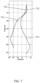
- FIG. 7 is an examplary graph illustrating the curves extracted from the sagittal X-ray images of FIGS. 5 and 6 .
- Curve 702 corresponds to the curve drawn on the sagittal X-ray image of FIG. 5
- curve 704 corresponds to the curve drawn on the sagittal X-ray image of FIG. 6 .
- Curves 702 and 704 are obtained by quantifying the color of the curves 504 and 604 drawn on the sagittal X-ray images of FIGS. 5 and 6 , and finding differences in red, green, blue, intensity, hue, saturation, contrast, and brightness to identify the central sacral vertical line at every pixel. This image processing may result in thousands of data points to form curves 702 and 704.
- FIG. 8A is an examplary graph illustrating a three-dimensional model rotated to the sagittal view.
- the three-dimensional model includes a preoperative curve 802 and a postoperative curve 804.
- the sagittal view of FIG. 8A shows that the surgeon corrected the spine to put it in proper alignment.
- FIG. 8B in which the three-dimensional model is rotated to the coronal view, the spine is out of balance.
- the postoperative curve 804 shows that the patient is leaning the patient's right.
- this information is useful in performing future spinal surgeries on the patient whose spine is illustrated in FIGS. 8A and 8B , or on other patients who have not yet undergone surgery.
- the surgical device may be designed to counter the spine's movement to the right as shown in FIG. 8B .
- FIG. 9 is an examplary graph illustrating a three-dimensional model of a spine over a fourth dimension, e. g. time, from a preoperative state to a postoperative state at times 901, 903, 905, 907, 909
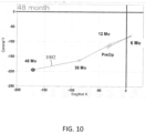
- FIG. 10 is an example graph illustrating a four-dimensional model of the movement of a head from a preoperative state to a postoperative state.
- the curvature of the spine is changing from coronal and sagittal balance to an imbalanced state.
- these models of the curvature of the spine over time may be used to predict the change in curvature of a spine of a similarly-situated patient who is being prepared for spinal-alignment surgery.
- the curvature of the spine that has undergone surgery is changing such that the position of the head is moving forward and to the right of a normal position of the head.
- first patient has similar preoperative spine positions and medical conditions as a patient who has not yet undergone a similar spinal surgery
- second patient the system of the present disclosure may predict that the second patient's spine will change positions in a way similar to the spine of the first patient. If there are any differences between the first and second patients, those differences may be used to adjust the predicted change in positions of the second patient's spine.
- the predicted change in the positions of the second patient's spine may then be used to determine the parameters, e.g., dimensions, angles, or configurations, of the surgical device to be deployed in the second patient so as to counter the changes in positions of the second patient's spine in a case where the predicted changes in the positions of the second patient's spine results in at least one of coronal imbalance or sagittal imbalance.
- the determined parameters of the surgical device may be translated into instructions or commands for a milling machine or a three-dimensional printer to manufacture or form the surgical device.
- the predicted change in the positions of the second patient's spine may be used to adjust the parameters, e.g., dimensions or configurations, of one or more adjustable surgical devices, e.g., intervertebral devices used to achieve a desired curvature of the spine, that already have been deployed in the second patient's spine.
- adjustable surgical devices are described in U.S. Patent Nos. 9,585,762 , 9,393,130 , 9,408,638 , 9,572,601 , and 9,566,163 , and in Pub. Nos. WO 2017/027873 , US 2016/0166396 , US 2016/0317187 , and US 2016/0022323 .
- the predicted change in the positions of the second patient's spine may be used to determine and employ appropriate surgical procedures for deploying a surgical device in the second patient's spine.
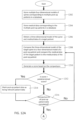
- FIG. 11 is a flow diagram illustrating a process for performing spinal surgery using a four-dimensional model in accordance with some embodiments.
- a computer obtains coronal X-ray images and sagittal X-ray images of the first spine captured at different times.
- the X-ray images are captured at different times during a preoperative period and during a postoperative period.
- lines or curves are drawn through vertebral bodies of the first spine shown in the coronal and sagittal X-ray images. Specifically, image processing is applied to the coronal and sagittal X-ray images to recognize vertebral bodies and to locate a center point within the vertebral bodies through which the lines or curves may be drawn.
- a four-dimensional model is constructed based on the curves or lines drawn through the vertebral bodies of the first spine in the coronal and sagittal X-ray images. The lines or curves may be drawn by, for example, superimposing pixels of a particular color on the coronal and sagittal X- ray images.
- the lines or curves are drawn by replacing existing pixels of the coronal and sagittal X-ray images with replacement pixels of a predetermined color, e.g., cyan or magenta.
- This process of drawing a virtual line or curve may be done according to image processes known to those skilled in the art. Note, any color and virtual line are used as visual aids to assist in generating the CVBL.
- the module 2201 only needs several selected points on the image to interpolate the actual X, Y, and Z coordinates of the CVBL.
- a three-dimensional model of a second spine is analyzed in view of the four-dimensional model of the first spine to determine parameters of the surgical device for the second spine.
- the three-dimensional model of the second spine is also analyzed in view of medical data pertaining to both the first and second spines. For example, if the first and second spines are the same or similar in a preoperative state, and the medical data pertaining to both the first and second spines are similar, a prediction can be made that the first spine will behave similarly to the second spine during a postoperative period. Thus, the surgical device applied to the first spine may be adjusted to avoid any alignment issues that arise in the second spine during the postoperative period.
- surgical device is constructed and deployed in the second spine based on the predictions made at block 1108 and based on parameters of the spinal column dimensions and needed surgical device.
- FIGS. 12A and 12B are flow diagrams illustrating a process for analyzing data from different patients and using that analysis to perform spinal surgery in accordance with some embodiments.
- multiple four-dimensional models of spines corresponding to multiple postoperative patients are stored in a database.
- medical data corresponding to multiple postoperative patients is stored in a database as well.
- a three- dimensional model of the curvature of the spine and medical data of a target patient are obtained for analysis prior to a surgical procedure.
- the three-dimensional model of the target spine is compared to a four-dimensional model of the curvature of a spine of many postoperative patients and the medical data of the target patient is compared to the medical data of those post-operative patients.
- a score may be generated based on the comparisons made between the models and between the medical data of the target patient and the postoperative patients.
- a higher score may be applied to a four-dimensional model that, in the preoperative state, most closely resembles the three-dimensional model of the target spine and the medical data of the target patient is closely related to the medical data of the postoperative patient.
- one score may be generated based on the comparison of the models and another score may be generated based on the comparison of the medical data.
- the computer determines whether the score is greater than a predetermined score. If the score is greater than a predetermined score, the postoperative patient data is marked as being relevant patient data at block 1214. At block 1216, the computer determines whether comparisons have been completed for all postoperative patient data. If there is more post-op patient data, the process returns to step 1208 to compare models and medical data of the patients. If the comparisons have been completed, the four-dimensional models of marked postoperative patients are consolidated to create a consolidated four-dimensional model.
- motion vectors are determined based on the consolidated four-dimensional model.
- motion vectors of the spine of the target patient are estimated based on the determined motion vectors.
- dimensions of a spinal surgical device are determined based on the estimated motion vectors of the spine of the target patient and three-dimensional parameters of length, width, and height of patient anatomic data.
- machine-readable instructions for controlling a machine to construct the spinal surgical device are generated and are transmitted to the machine. In this manner, a surgical device may be constructed that accounts for estimated vectors to ensure that the target patient's spine maintains coronal and sagittal balance during the postoperative period.
- machine-readable instructions for controlling a machine to modify an existing spinal surgical device are generated and are transmitted to the machine, e.g. a machine designed to bend spinal rods beyond their current configuration.
- the movement of the spine may be predicted using a model.
- the shape of a spine can be defined by a mathematical equation. These equations can be modeled statistically using a spline or a non- linear regression.
- a normal spine is made up of two, connected, logistic ogives, which are also known as sigmoidal or S-shaped curves.
- the spline may be the easiest curve to fit and may provide useful information.
- the nonlinear regression provides more information, which, in certain applications, may be better.
- Predictive analytics comes into play when the relevant medical data for a patient is known before the surgery.
- the relevant medical data may include the diagnosis, cobb angle, and/or Lenke classification. Then, a cohort of patients is found in a database that have the same or similar characteristic medical data.
- a new patient may be diagnosed with Adolescent Idiopathic Scoliosis (AIS) and a Lenke 1A curve.
- AIS Adolescent Idiopathic Scoliosis
- Lenke 1A curve the relevant medical data for the new patient is known.
- the database there may be a number of old patients (e.g., 100 old patients) with AIS and Lenke 1A curves having the same or similar characteristic medical data.
- the medical data of the old patients in the database may include, among other medical data, the following:
- this medical data (which may be represented as variables) may be combined together using Boolean logic (e.g., AND, OR, NOT) as predictors to the new patient and factored in as probability functions. Then, an outcome metric is determined or chosen. For example, if global balance (which means head-over-pelvis) AND posterior surgical approach AND thoraco-lumbar junction was crossed AND titanium hardware (screws and rods) were used NOT (pelvic tilt (this measure was irrelevant) OR blood loss (did not matter)), the probability of success of the surgery for the new patient may be 92.4%. But if the transverse ligament is cut on the concave side (intraoperative data), the probability of success of the surgery for the new patient may drop to 73.5%. In embodiments, some or all of the relevant medical data may be used to predict movement of the new patient's spine after surgery, which, in turn, may be used to determine the probability of success of the surgery performed on the new patient's spine.
- Boolean logic e.g., AND
- the disclosed system and techniques utilize statistical analysis in conjunction with more accurate models of patients' spines to determine the parameters of spinal devices.
- the system and process for developing a three-dimensional model comprising a set of spatial coordinates which can be plotted in three dimensions and which characterizes the shape of the spine, not by angles but by spatial coordinates Euclidean space, has been described with reference to Figures 1 through 12 herein.
- the nature of the spinal model allows it to be compared with other axes of reference and the variance there between quantified.
- the variance may be a numerical value used to indicate how widely spinal curvature fluctuates around the axis of the patient representing the head over pelvis (HOP).
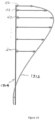
- a line 1312 representing the curved shape of a three-dimensional spinal model created in accordance with the techniques described herein, is shown in relation to a vertical line 1314 representing a reference axis, which in this example is the Z axis serving as an idealized head over pelvis line.
- Points comprising line 1312 each have a distance d1, d2, d3...dn from line 1314, as illustrated.
- a numerical variance value and standard deviation for each of the sagittal and coronal planes may be calculated and a composite total variance and standard deviation of the spine relative to the reference axis may be determined.
- Equation 1 VAR X + VAR Y
- the variance value may be used as a predictive indicator of the pressure and force to which a spinal device, a such as a rod, may subjected and may be further used to suggest parameters for modification or manufacturing of the spinal device, so that the faces to be used in spinal models having greater variance may need to be modified, e.g. over bending of rods in anticipation of torqueing forces from the spine once implanted.
- systems and methods for rapid generation of simulations of a patient's spinal morphology enable pre-operative viewing of the patient's condition and to assist surgeons in determining the best corrective procedure and with any of the selection, augmentation or manufacture of spinal devices based on the patient specific simulated condition.
- the simulation is generated by morphing a generic spine model with a three-dimensional curve representation of the patient's spine derived from existing images of the patient's condition.
- FIG. 15 is a block diagram illustrating an exemplary system architecture for rapid generation of simulations of a patient's spinal morphology.
- an X ray apparatus 12 provides X-ray images to a cloud server 16.
- the cloud server 16 may be secured in such a way that it complies with the privacy protection provisions of the Health Insurance Portability and Accountability Act of 1996 (HIPAA).
- HIPAA Health Insurance Portability and Accountability Act of 1996
- the X ray apparatus 12 provides X-ray images to a computer or a server that may better protect patient information than cloud server 16.
- the X ray apparatus 12 may be any X-ray apparatus that is configured to capture X ray images of the human skeleton.
- the system architecture 10 may also include a medical database 14 that transmits and stores medical data in the cloud computer or server 16.
- the medical database 14 may reside in a doctor's office or in a hospital and may contain a variety of medical data that is useful in determining the method of performing spinal surgery and the parameters of the spinal device that is used to correct the misalignment of the spine.
- This medical data may include all medical conditions that are or may be relevant to the spine, including, for example, osteoporosis, adolescent idiopathic scoliosis, adult scoliosis, neuromuscular disease, and degenerative disc disease.
- the medical data may include one or more of the following: patient demographics, progress notes, vital signs, medical histories, human clinical data, diagnoses, medications, Cobb Angle measurements, adverse events, operative complications, implant complications, operative time, blood loss, immunization dates, allergies, X-ray images, such as coronal and sagittal X-ray images, and lab and test results.
- Cloud computer server 16 may store the X-ray images and medical data in a way to allow for easy access by computer 11 that has access to the cloud computer or server 16.
- Computer 11 using display 12 may display the X-ray images and the medical data to assist a clinician in planning for and performing a spinal surgery.
- the computer 11 may then analyze the X-ray images and the medical data to determine instructions for constructing a simulation of the spinal morphology of a patient's vertebral body for pre-operative visualization and to further simulate the predictive outcomes visually of multiple degrees of corrective surgery.
- the above described process is repeated for some or all of the other vertebral bodies in the spine, resulting in a three-dimensional simulation of the vertebral bodies in a patient spine, similar to that illustrated in FIG 23B .
- the computer 11 may interact with a surgeon mobile device 15 or a patient mobile device 17 is illustrated.
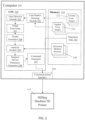
- FIG. 16 is a block diagram illustrating computer 2110 and system architecture 10 of FIG. 15 .
- Computer 110 includes central processing unit 2200 and memory 2210.
- a portion of the X-ray images stored in cloud server 16 are retrieved from the cloud server 16 by computer 11 and stored in memory 2210.
- the X-ray images retrieved from cloud server 16 may include coronal X-ray images 2212 and sagittal X-ray images 2214 of one or more spines.
- Computer 11, under the control of the central processing unit 2200 may also retrieve one or more electronic medical records 2218 and/or spine models 2216 from cloud server 6.
- Memory 2210 may also store statistical data representing normal spine model 2216 that is used to generate a three-dimensional simulation of a patient's morphology.
- module 2216 may store multiple different spine models that may be separately selectable based on different parameters such as any of gender, age, height range, weight range, specific pathologies, and/or risk factors such as smoking and/or alcohol use, etc.
- Such models may be in the form of a point cloud or may be in a format, such as CT scan data, from which a point cloud model may be derived.
- Components of the system of the present disclosure can be embodied as circuitry, programmable circuitry modules configured to execute applications such as software, communication apparatus applications, or as a combined system of both circuitry and software configured to be executed on programmable circuitry.
- Embodiments may include a machine-readable medium storing a set of instructions which cause at least one processor to perform the described methods.
- Machine-readable medium is generally defined as any storage medium which can be accessed by a machine to retrieve content or data.
- machine readable media include but are not limited to magnetooptical discs, read only memory (ROM), random access memory (RAM), erasable programmable read only memories (EPROMs), electronically erasable programmable read only memories (EEPROMs), solid state communication apparatuses (SSDs) or any other machine-readable device which is suitable for storing instructions to be executed by a machine such as a computer.
- the CPU 2200 executes a number of computational modules, each of which is programmed to perform specific algorithmic functions, including a curvature detection module 2215, a morphing module 2204, material analysis module 2206, a rendering module 2206, and a User Interface module 2207.
- the curvature detection module 2215 further comprises a CVBL generator 2201, point map module 2202 and orientation module 203. Curvature detection module 2215 provides the primary input data for morphing module 2204 and material analysis module 2205.
- the morphing module 2204 morphs the three-dimensional simulated patient spine model into a preoperative condition, as explained herein yielding a three-dimensional simulated patient spine model, as illustrated in FIG. 23B .
- Material module 2205 enables altering the three-dimensional simulation by a predetermined amount or to the percent of correction from the surgeon input to enable preoperative visualization and/or prediction of the amount of correction required for a particular patient's spinal morphology.
- Rendering module 2206 visually creates an a virtual image to show the surgeon and/or patient the appearance of their spine, as simulated.
- the processes executed by CPU 2200 are described with reference to the flow diagrams of FIG. 17 and FIG. 18 below and as described elsewhere herein.
- FIG. 17 is a flow diagram illustrating a process for performing spinal surgery in accordance with some embodiments.
- the CVBL generator 2201 processes the sagittal and coronal X-ray data, calibrates the image data to establish a common frame of reference, and then creates a Central Vertebral Body Line (CVBL), as illustrated at block 1302.
- CVBL Central Vertebral Body Line
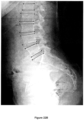
- FIGS. 19A and 19B are X-ray images in the sagittal and coronal planes of the lumbar spine, respectively, annotated with a visually detectable scaling reference.
- the vertebral body central points 1902, 1904, 1906, 1908, and 1910 along spline 1920 are overlaid on the virtual x-ray image and illustrate a portion of the data utilized to generate a central vertebral line for the subject.
- Any image files or data format may be utilized, including DICOM images, by the CVBL generator 2201.
- the coronal and sagittal X-ray images may be X-ray images of a spine and may be obtained prior to the surgical procedure.
- the X-ray images may also include images that were obtained both before and after a previous surgical procedure, e.g., a procedure performed on the spine.
- the three-dimensional simulation starts with either the creation or retrieval of a virtual model of each vertebral body in a set of vertebral body models and results in rendered vertebral bodies, as illustrated at block 1304.
- the curvature detection module 2215 and morphing module 2204 generate a three-dimensional simulation of a patient's spine morphology by morphing a normal spine model with a Central Vertebral Body Line representing an individual patient's spinal morphology to generate the three-dimensional simulation, as illustrated at block 1306, and as described herein.
- the materials module 2205 enables the surgeon to input patient specific data which can be used to modify the three-dimensional simulation based on surgeon input of patient specific, as illustrated at block 1308.
- Rendering module 2206 and User Interface 2207 enable the three-dimensional simulation of the patient spine morphology, with or without further input from the surgeon, to be rendered in normal or Virtual-Reality/Augmented Reality (VR/AR) format, as illustrated at block 1308.
- VR/AR Virtual-Reality/Augmented
- each vertebral body model is in the form of a point cloud representation of the vertebral body, the point cloud comprising as a series of points in three-dimensional space. Point clouds can be generated from any of a number of sources.
- FIG. 18 is a flow diagram illustrating in greater detail the process illustrated in block 1304 of FIG. 17 .
- the process starts with multiple surface scans of the coronal and sagittal X-rays of a subject that produce approximately 1000 points for each vertebral body which point map module 2202 uses to create a point map of a vertebral body, similar to the point cloud map shown in Figures 20A-B , as illustrated by block 1402.
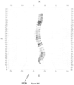
- the images in Figures 20A-B are the point cloud 2220 for vertebral body L4, with the sagittal view shown in Figure 20A and axial view shown in Figure 20B .
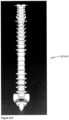
- Morphing module 2204 uses a point cloud model for each vertebral body and can generate a simulation of a patient's morphology in a point cloud for the entire spine, similar to spinal point cloud model 2230 as illustrated in the image of Figure 20C . All or a portion or none of the spine simulation may be rendered with surfaces as described elsewhere herein.
- Each point in a point cloud map may be connected to two or more other points to generate a face with vectors associated with such points and faces.
- the vectors describe the direction and displacement of the points in the point cloud model comprising the virtual vertebral body model.
- morphing of the point cloud model to simulate an individual patient's actual deformity requires modifying those vectors.
- morphing module 2204 performs a translation of all of the points in a vertebral body point cloud model. From the output of point map module 2202, the X, Y, Z spatial coordinates of a central point on each of the vertebral bodies form a centerline that collectively comprises a curve representation in three-dimensional space describing the deformity of an individual's spine in three dimensions.
- Morphing module 2204 utilized the spatial coordinates output of module 202 and translates all the points in a vertebral body point cloud model in a given direction as determined by the output of point map module 2202.
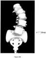
- a spine model as illustrated in Figures 21A-B , has the points comprising in the respective vertebral body models thereof translated spatially according to corresponding points on the CVBL to simulate the arrangement of center points of the vertebral bodies along the CVBL, as illustrated by the image of Figure 21C .
- translation alone of spatial coordinates will not necessarily yield a realistic simulation.
- the center line of each VB is in the correct location on the CVBL but notice that the vertebral bodies have slid off of one another, a.k.a.
- subluxation that does not realistically simulate the proper orientation of adjacent vertebral bodies relative to each other. This is because normal spines have a glue between the vertebral bodies, i.e. the disc, which prevents such sliding.
- adjacent vertebral bodies are angled and/or rotated due to the deformity of a patient's particular morphology.
- the disclosed system and technique simulate actual movement of the vertebral bodies in the spinal column by utilizing a combination of translation, angular displacement and angular rotation of the respective vertebral bodies to simulate a patient morphology.
- orientation module 2203 automatically identifies each disc and the endplates of the adjacent VBs in an image. Given this information, the length and height of each VB structure is calculated in both the sagittal and coronal planes.
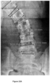
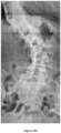
- FIGS. 22A and 22B are X-ray images in the coronal and sagittal planes, respectively, annotated with lines representing the discs and endplates of vertebral bodies. In one embodiment, the end plates of vertebral bodies may be annotated in different colors.
- orientation module 2203 may generate a user interface that enables a user to manually mark the end plates of vertebral bodies on an image. Orientation module 2203 may then calculate measurements of various marked features and store the results thereof.
- a first method for rapid generation of a simulated patient morphology is illustrated in the flowchart of Figure 18 .
- the center of vertebral body S1 endplate is used as a reference pivot point by which each point in every point cloud model of a vertebral body is pivoted, translated, and rotated, and proportionally scaled, as necessary, relative to the reference pivot point.
- the CVBL generator 2201 processes the image data, calibrates the image data to establish a common frame of reference, and creates a Central Vertebral Body Line, as previously described, a model, e.g.
- the vertebral body models may be a generic normal set of vertebral bodies unrelated to the specific patient or, alternatively, the vertebral body models may be derived from the patient's medical image data, such as from CT scan data, or a combination of both.
- the end plates or edges of the vertebral bodies of interest on one or both images are identified through either manual input, received through a user interface generated by module 2207, or by an automated detection algorithm executable by orientation module 2203, as illustrated by the images in FIGs. 22A-B .
- orientation module 2203 determines the slope and midpoint of the vertebral body endplates in each of the sagittal and coronal planes for each vertebral body and then calculates the angulation vectors in each of the sagittal and coronal planes, as illustrated at block 1404. The orientation module 2203 then calculates the translation and tilt angles to the center point of each of the vertebral bodies, e.g. cervical, thoracic, lumbar, sagittal, and coronal, and the angular rotation vectors, and then translate all the points in the corresponding vertebral body point cloud model relative to their original coordinates, as illustrated at block 1406.
- the morphing module 2204 pivots the point cloud models around the center point of vertebral body S1, as illustrated at block 1408. Note, once the pivot point and the x,y,z coordinates of the points in a point cloud model are known, the point cloud model can be morphed in any order, e.g. translated, rotated, and then angled, or, angled, rotated, and then translatde, or in other procedural orders, etc., with the same result.
- the simulation may be rendered on a display by rendering module 2206 and UI interface VR/AR module 2207, as illustrated at block 1410.
- the simulation may be all partially rendered with surface features.
- FIG. 23B is an image of a three-dimensional simulation 2300B of a morphed three-dimensional spine derived from the actual patient coronal X-ray of FIG. 23A using the systems and methods described herein.
- the above method can be used for any of the lumbar, thoracic and cervical spine simulations.
- the base pivot/translate point may be used as the base pivot/translate point about which the other point cloud models of vertebral bodies will be referenced.
- vertebral bodies L3, L4 and L5 are morphed according to the morphology of the X-ray of FIG. 23A with L3 angulated and very close to touching L4 simulating the actual patient's morphology, as seen in the actual the X-ray of FIG. 23A .
- the above described method can be used for any of Lumbar, Thoracic, or Cervical spine simulations.
- FIG. 23C illustrates a simulation 2300C, in which only translation of each vertebral body center point was utilized without angulation or rotation of the respective vertebral bodies relative to a reference point, such simulation suffering from the effects of subluxation, similar to the simulation 2120 of FIG. 21C .
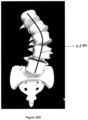
- FIG. 23D is an image of simulation 2300B, similar to that illustrated of FIG. 23B , but annotated with a line 2340 representing the CVBL about which the point cloud models of the vertebral bodies were translated pivoted and/or rotated to create the simulation 2300B.
- a second method for rapid generation of a simulated patient morphology is disclosed and is a variant to the process illustrated in the flowchart of Figure 18 .
- the left/right/front/back edge end points of each vertebral body of interest are identified by orientation module 2203 and a three-dimensional shape of each of the vertebral bodies is created. Because the shape, typically an irregular boxlike construct is defined by spatial coordinates, the dead center of each box may be determined, with the center point of a vertebral body box serving as a reference pivot point. Every other point in the point cloud model for that individual vertebral body may then be pivoted, angled, translated, and proportionally scaled relative to this reference pivot point, similar to the process described with respect to block 408.
- each of vertebral body inherently contains the respective spatial coordinates of the edges and corners of the box, rotation of the vertebral body relative to a reference point, such as the center point of vertebral body S1 or other reference point on the patient image, in the first described method, is not required.
- the data determining how the point cloud model of a vertebral body will be rotated is determined differently.
- the CVBL provides the translation data to move a vertebral body point cloud model to the correct spatial locations, and further provides the angulation data to tilt the vertebral body point cloud model so that its approximate center lies within the CVBL.
- the reference point S1 is used to serve as the basis on which the rotation data, generated by measurement of the endplates and other characteristics of the vertebral bodies, is derived.
- Such rotation data is used to rotate the translated and tilted the vertebral body point cloud model into an orientation relative to the other VBs in a manner that more accurately simulates the patient's morphology.
- the angulation data and the rotation data are determined by the center point of the vertebral body point cloud box which is initially assumed to lie on the CVBL, but, which after taking appropriate end plate and other measurements, may be determined to lie elsewhere.
- the appropriate translation scaling factors are used to tilt and appropriately rotate the points comprising the vertebral body point cloud model into appropriate orientation, without the need for an external reference point, such as S1, since the spatial coordinates describing the three-dimensional box of each of vertebral body inherently define the rotation of the VB relative to its respective center point.
- a third method is used for simulating spinal pathologies that are relatively simple deformities, such as Scheurmann's kyphosis, a Lenke 1A or a simple 5C.
- all of the vectors associated with the point cloud of a VB are not calculated and morphed (translated, angled and rotated). Instead the central pivot point for each vertebral body, which happens to run through the CVBL, generated as previously described, is identified.
- a number of pixels, e.g. 5, both above and below a pivot point on the CVBL are examined and the slope in both the sagittal and coronal planes calculated. In the illustrative embodiment, these 10 pixels are approximately 1 mm in length.
- the calculated angles are then applied to the point cloud model of a vertebral body and used to generate the image. This process is then repeated for each vertebral body of interest within the original images from which the simulation was derived.
- morphing module 2204 generates two separate tables with the data describing the spacial coordinates and other information describing the simulation for not only the CVBL but also each point in the point cloud model of each of the vertebral bodies within the spine. Such data set can be provided to rendering module 2206 to recreate the three-dimensional reconstruction appears.
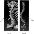
- FIG.24A illustrates a traditional three-dimensional reconstruction 2400A of the patient spine of FIG. 23A generated from CT scan data which required substantial computing resources to generate.
- FIG. 24B illustrates a morphedthree-dimensional simulation 2402 of the patient spine image of FIG. 23A generated using the methods herein which were created in a matter of minutes.
- the three-dimensional simulation 2402 has been extended all the way up the spine with every vertebral body simulated and illustrated. Note, however, the vertebral bodies of simulation 2402 are smaller than the actual vertebral bodies in the CT scan reconstruction 2400 even though both recreations are in the same scale and in the same coordinate system.
- the system described herein is capable of scaling the size of the individual vertebral bodies within the simulation 2402 by predetermined amounts or based on user defined input. Because each vertebral body in a simulation is modeled with a point cloud having a single, centrally located pivot point, such scaling entails expanding or contracting each vertebral body around the point cloud model central pivot point. Since the X, Y, Z coordinate of the central pivot point of a vertebral body is know and the three-dimensional distance to each of the points in the point cloud model of the vertebral body are also known, all points in the point cloud model associated with a vertebral body may be expanded (or contracted) with a proportional scaling factor.
- the three-dimensional distance from the central pivot point of the vertebral body to a point in the vertebral body point cloud is multiplied by 0.9.
- the three-dimensional distance as from the central pivot point of the vertebral body to a point in a vertebral body point cloud is multiplied by 1.25.
- Such scaling factor can be applied to any or all of the sagittal (x), coronal (y) or height (z) values of a vertebral body at once. All or selected vertebral bodies within a simulation can be scaled simultaneously.
- 24D illustrates a three-dimensional simulation 2404 of the patient's vertebral bodies which have been scaled in comparison to the unscaled simulation 2402 in FIG. 24B .
- Such scaling may be performed by an algorithmic process in rendering module 2206 in conjunction with module 2207 to enable interactive the scaling when the simulation image appears, e.g. the process queries through the user interface 2600, "Is this a good approximation?". If the user's answer is "no", the process may then receive user-defined input value, e.g. 12%, and then re-executes the proportional scaling of the simulation again as many times as necessary until the user is satisfied.
- user-defined input value e.g. 12%
- an algorithm creates a series of surfaces or faces among the points in the point cloud model describing a vertebral body, as illustrated by block 1404.
- Vectors normal to each point in the point cloud model and normal each polygon face are determined through a summation process relative to a hypothetical center point of the vertebral body, which hypothetical center point may lie within the Central Vertebral Body Line, and determine the orientation of the vertebral body in three dimensions, as illustrated in blocks 1408. This process is then repeated for all vertebral body models in the patient spine, in which the arrangement/morphing of each vertebral body, e.g. any of translation, angular displacement and angular rotation, may occur iteratively.
- FIG. 23B is an image of a morphed simulated three-dimensional spine derived from the actual patient coronal X-ray of FIG. 23A similar to that using the systems and techniques discussed herein.
- Such simulation of a patient spine may then be further morphed by the morphing module 2204 in response to a pre-determined percentage of correction as specified by a surgeon through the material module 2205, as illustrated by block 1414, as explained elsewhere herein.
- the curvature detection module 215 processes sagittal and coronal X-rays, although any image files or data format may be utilized, including DICOM images.
- the CVBL generator 2201 calibrates the image data to establish a common frame of reference and then creates a Central Vertebral Body Line. Curvature detection module 2215 either acquires or calculates the following variable values:
- the data generated by curvature detection module 2215 also forms the basis for other calculations including two nonlinear regression equations, (Sagittal vs Height and Coronal vs Height), r2 (coefficient of determination) point estimates, three-dimensional Plots, and three-dimensional measurements table.
- the functionality of the curvature detection module 2215 may be partially implemented with a software application named Materialise 3Matic, commercially available from Materialise, Madison, MI that is intended for use for computer assisted design and manufacturing of medical exo- and endo-prostheses, patient specific medical and dental/orthodontic accessories and dental restorations.
- the functionality of the curvature detection module 2215 may be further partially implemented with a software application named Materialise Mimics, also commercially available from Materialise, Madison, MI, which is an image processing system and preoperative software for simulating/ evaluating surgical treatment options that uses images acquired from Computerized Tomography (CT) or Magnetic Resonance Imaging (MRI) scanners.
- CT Computerized Tomography
- MRI Magnetic Resonance Imaging
- the Materialise Mimics software is intended for use as a software interface and image segmentation system for the transfer of imaging information from a medical scanner such as a CT scanner or a Magnetic Resonance Imaging scanner to an output file.
- materials module 2205 enables the three-dimensional simulation of the patient specific morphology to predictively undergo preoperative mechanical testing.
- Material module 2205 is a preoperative planning tool that makes mechanical calculations and visually guides the surgeon through the process of choosing the correct hardware. Because curvature detection module 2215 generates a table or other data structure of three-dimensional spatial coordinates, e.g. X, Y, and Z, all of the equations of state in the fields of mechanical engineering, physics, mathematics and materials science are available, including the ability to determine and calculate stress/strain and fatigue in bone, or any implant materials, including CoCr, Ti-6AI-4V. When the positions of pedicle screws, rods, and interbodies are know, along with the materials from which such items are made, statistical analysis is possible enabling calculations like truss analysis, three and four point bend tests, and calculating the stress distribution at certain points.
- materials module 2205 generates 2 x 24 array of data representing visual structures or icons of the posterior pedicles of the spine that are morphed with a patient's pre-op curve as generated by the curve detection module 2215 in a manner described herein.
- the structures are geometric in shape.
- FIG. 26 is a screen shot of a user interface 2600 by which a surgeon enters various data through a series of either drop down menus or slider bars or dialog boxes to enter any patient specific parameters, including things like, location of pedicle screws, screw material, rod dimensions and materials, patient risk factors (smoker, drinker, BMI, etc.), age, height, curve stiffness, everything specific to that patient.
- An accumulated human clinical database may provide a level of detail to look at how patients' spines deform for every given morphology and enables the use of predictive analytics for outcomes, including any of 30 day hospital readmission, PJK, QoL scores, revision surgery, etc.
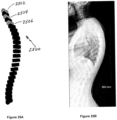
- FIG. 25A illustrates conceptually the 2x24 pedicle model array 2500 of a patient spine morphed in three dimensions and rotated to show partial sagittal and coronal views in which the pedicle pairs 2502, 2504 and 2506, representing C1, C3 and C5, respectively, have been colored or designated with some other visual indicator.
- FIG 25B is a sagittal X-ray of the patient from which the simulation was derived, in further consideration of the input parameters illustrated in the screen shot of the user interface 2600 generated by module 2207, as illustrated in FIG. 26 .
- the visual representation of the anatomical structure e.g. the posterior pedicles, may be any geometric shape or other visually discernible indicator, the purpose of which is to be arranged to simulate the approximate location thereof without the need for the exact details of the structure as described in the other processes disclosed herein.
- Material module 2205 enables stress calculations, surgical pre-operative planning and predictive analytics.
- the surgeon may more accurately choose the appropriate hardware capable of postoperatively achieving the desired percentage of correction of the patient's specific morphology..
- the disclosed system and techniques enables the ability to morph simulations of spines, both two-dimensional and three-dimensional, in any increment, e.g.10% intervals, 5% intervals, 0.1% intervals. Knowing how much to move/morph the spine increases the predictive analytics capabilities and, therefore, the likelihood of success of a procedure. Because the disclosed system enables calculations in three-dimensional space, any of the previously listed variable parameters may be manipulated.
- the rendering module 2206 and interface module 2207 creates a visual image of the three-dimensional simulation that illustrates how the patient may look after surgery that may include an outline of the skin (shoulder imbalance, rib hump, thoracic kyphosis, etc.) in a pre-operative condition and morphing the simulation into the post-op positions.
- the rendering module 2207 utilizes two white light photographs (or X-rays if they include the patient's skin), one sagittal and one coronal to achieve such rendering.
- a portable spine application which may be part of the user interface module 2207 converts the three-dimensional simulation model rendered by module 2206 and converts the simulation into a virtual reality (VR)/ augmented reality (AR) format, using any number of commercially available applications, which is then made available to the surgeon on his/her phone or other portable device 15, as well as the patient on their portable device 17.
- module 2207 may generate an VR/AR overlay in either the supine position while lying on the table, prepped for surgery to enable the surgeon to visualize the procedure in real time, or the final post-operative configuration.
- a standing X-ray looks nothing like the supine position.
- the disclosed system and techniques enables the morphing of the patient spine in two-dimensional and three-dimensional simulations and have simulation over-layed with surgeon vision using either Virtual or Augmented Reality.
- DICOM Digital Imaging and Communications in Medicine
- CT scans and MRI images are typically three-dimensional and, using the techniques described herein, enable physics and mathematics to be applied to the modeled entities to gain more realistic models and simulations of the spine. Metrics such as areas, volumes, moment of Inertia for cubes, prisms, cylinders, and even internal organs may be calculable.
- a simulation of the patient specific (deformed) spine was created in three-dimensional in less than 1.5 minutes.
- the disclosed system and techniques can show the surgeon and patient a simulation of what the spine currently looks like and what it may look like after surgery.
Landscapes
- Health & Medical Sciences (AREA)
- Engineering & Computer Science (AREA)
- Life Sciences & Earth Sciences (AREA)
- Surgery (AREA)
- General Health & Medical Sciences (AREA)
- Medical Informatics (AREA)
- Physics & Mathematics (AREA)
- Molecular Biology (AREA)
- Biomedical Technology (AREA)
- Heart & Thoracic Surgery (AREA)
- Animal Behavior & Ethology (AREA)
- Public Health (AREA)
- Veterinary Medicine (AREA)
- Nuclear Medicine, Radiotherapy & Molecular Imaging (AREA)
- Pathology (AREA)
- Biophysics (AREA)
- General Physics & Mathematics (AREA)
- Theoretical Computer Science (AREA)
- Physical Education & Sports Medicine (AREA)
- Robotics (AREA)
- Dentistry (AREA)
- Oral & Maxillofacial Surgery (AREA)
- Orthopedic Medicine & Surgery (AREA)
- Rheumatology (AREA)
- Computer Graphics (AREA)
- Computer Hardware Design (AREA)
- General Engineering & Computer Science (AREA)
- Software Systems (AREA)
- Architecture (AREA)
- Computer Vision & Pattern Recognition (AREA)
- Radiology & Medical Imaging (AREA)
- Quality & Reliability (AREA)
- Apparatus For Radiation Diagnosis (AREA)
Description
- This disclosure pertains generally to modeling aspects of the human skeleton, and, more particularly, to developing and using models of a spine and using other medical data relating to the spine to visualize and predict the results of a surgical procedure prior performing spinal surgery so as to result in a desired outcome, such as a balanced spine.
- Today a wide-variety of surgical devices are being developed and used to perform various spinal surgical procedures. In many spine surgeries, surgical devices are used to correct a patient's spine so that the skull is oriented over or aligned with the pelvis. Specifically, the surgical devices and software are used to ensure that the vertebral bodies are in normal sagittal alignment so that there is a gradual transition of curvatures from cervical lordosis, to thoracic kyphosis, to lumber lordosis. Although such spinal surgery may result in normal sagittal alignment of the spine, the spine may not be properly aligned in either of the coronal or axial planes. One reason for only partial correction is that surgeons typically focus on spinal models that are described predominantly by angular data as measured among vertebral bodies in the sagittal plane, instead of actual spatial coordinates. Another reason for only partial correction is the failure to consider alignment of the spinal column in the coronal or axial planes as well as the sagittal plane. A further reason for only partial correction is the failure to use the alignment of the head with the center of the pelvis as an axis of reference in which to measure the deviation of the modeled spinal column in both the sagittal and coronal planes. A further reason for only partial correction is the inability to predict post-surgical results with even marginal accuracy. Computer modeling of a patient spine is currently available but requires prohibitively high computational resources.
- Accordingly, a need exists for a systems and methods for constructing a three dimensional simulation of the curvature of a patient spine which accurately reflect the morphology of the patient.
- A further need exists for a systems and methods for constructing a three dimensional simulation of the curvature of a patient spine which accurately reflect the morphology of the patient and can be generated quickly.
- A still further need exists for a systems and methods for constructing a three dimensional simulation of the curvature of a patient spine which accurately reflect the morphology of the patient and which can be further modified based on data input from a surgeon to enable better prediction of post-surgical results.
- An even further need exists for a systems and methods for constructing a three dimensional simulation of the curvature of a patient spine which accurately reflect the morphology of the patient and using other medical data relating to the spine to customize spinal devices and the methods of performing spinal surgery so as to result in a desired outcome, such as a balanced spine.
- According to another aspect of the disclosure, prior attempts at modeling the morphology of an individual patient spine's to assist surgeons with both pre-operative and post- operative analysis has required very costly procedures which are then used to create either virtual or physical three-dimensional models of the patient's exact condition. Such modeling procedures are very resource intensive in terms of both time and cost typically taking hours of computing to render such models into a form usable by a surgeon and, accordingly, are not very practical for large-scale use by the medical community.
- Accordingly, further need exists for a system and method which allows for rapid modeling of the morphology of the patient spine using x-ray data or CT scan data or MRI data which takes significantly less time and is significantly less computationally intensive.
- An image analysis apparatus, image analysis method and computer-readable recording medium storing an image analysis program are known from document
US 2009/0232378 A1 . Positional relationships are automatically determined with higher accuracy in a predetermined direction between three-dimensional images representing a subject including a periodic structure having periodicity in the predetermined direction, with respect to the periodic structure. A positional correspondence is provisionally determined in a predetermined direction between two three-dimensional images including a periodic structure having periodicity in the predetermined direction, based on a criterion wherein the periodic structure contributes less to the determination. The provisionally determined correspondence is then corrected so that a position in one of the three-dimensional images corresponding to a position of the other three-dimensional image in the predetermined direction can be corrected within a range near the position in the former three-dimensional image in the predetermined direction, according to a criterion wherein the periodic structure contributes more. - Document
US 2014/0323845 A1 is directed to automated 3-d orthopedic assessments. Systems, methods, computer programs, and circuits can perform automated spinal assessments using a 3-D model and a 3D-patient image data set of the spine which do not rely on vertebral symmetry. - According to document
US 2015/0328004 A1 , a method of constructing a patient-specific orthopedic implant comprises (a) comparing a patient-specific abnormal bone model, derived from an actual anatomy of a patient's abnormal bone, with a reconstructed patient-specific bone model, also derived from the anatomy of the patient's bone, where the reconstructed patient-specific bone model reflects a normalized anatomy of the patient's bone, and where the patient-specific abnormal bone model reflects an actual anatomy of the patient's bone including at least one of a partial bone, a deformed bone, and a shattered bone, wherein the patient-specific abnormal bone model comprises at least one of a patient-specific abnormal point cloud and a patient-specific abnormal bone surface model, and wherein the reconstructed patient-specific bone model comprises at least one of a reconstructed patient-specific point cloud and a reconstructed patient-specific bone surface model; (b) optimizing one or more parameters for a patient-specific orthopedic implant to be mounted to the patient's abnormal bone using data output form comparing the patient-specific abnormal bone model to the reconstructed patient-specific bone model; and, (c) generating an electronic design file for the patient-specific orthopedic implant taking into account the one or more parameters. - Finally, document
US 2011/0295378 A1 discloses methods and devices relating to improved articular models, implant components, and related guide tools and procedures. In addition, methods and devices are disclosed relating to articular models, implant components, and/or related guide tools and procedures that include one or more features derived from patient-data, for example, images of the patient's joint. The data can be used to create a model for analyzing a patient's joint and to devise and evaluate a course of corrective action. The data also can be used to create patient-adapted implant components and related tools and procedures. - The herein claimed invention relates to a machine-readable medium storing a set of instructions according to
claim 1. Optional features are defined in the dependent claims. - Various aspects of the present disclosure are described hereinbelow with reference to the drawings, wherein:
-
FIG. 1 is a block diagram illustrating a system architecture for performing spinal imaging, analysis, and surgery in accordance with some embodiments; -
FIG. 2 is a block diagram illustrating a computer and surgical device manufacturing machine employed in the system architecture ofFIG. 1 ; -
FIG. 3 is a flow diagram illustrating a process for performing a spinal surgery in accordance with some embodiments; -
FIG. 4 is a flow diagram illustrating an example process for generating a model of a spine in the process ofFIG. 3 ; -
FIG. 5 is an X-ray image of a sagittal view of a preoperative spine illustrating the drawing of a virtual curve that passes through the vertebral bodies of the preoperative spine in accordance with some embodiments; -
FIG. 6 is an X-ray image of a sagittal view of a postoperative spine illustrating the drawing of a virtual curve that passes through the vertebral bodies of the postoperative spine corresponding to the preoperative spine ofFIG. 5 in accordance with some embodiments; -
FIG. 7 is an example graph illustrating the curves extracted from the user interfaces ofFIGS. 5 and 6 ; -
FIGS. 8A and 8B are diagrams illustrating the sagittal and coronal views, respectively, of preoperative and postoperative three-dimensional models of the curvature of a spine; -
FIG. 9 is an example graph illustrating preoperative and postoperative three-dimensional models of the curvature of the spine for follow-up time periods in accordance with embodiments; -
FIG. 10 is an example graph illustrating a four-dimensional model of the movement of a head from a preoperative state to a postoperative state; -
FIG. 11 is a flow diagram illustrating a process for performing spinal surgery using a four-dimensional model in accordance with some embodiments; and -
FIGS. 12A and12B are flow diagrams illustrating a process for analyzing data from different patients and using that analysis to perform spinal surgery in accordance with some embodiments; -
FIG. 13 is a conceptual illustration of a line representing the curvature of a model spine relative to the Z axis from one of the coronal or sagittal planes; -
FIG. 14 is an X-ray image of a coronal view of a preoperative spine annotated with lines representing the Z axis and the patient HOP axis extending from the center of the pelvis to a vertebral body at the base of the skull; -
FIG. 15 is a block diagram illustrating a system architecture for performing spinal imaging, analysis, and simulation in accordance with the disclosure; -
FIG. 16 is a block diagram illustrating a computer employed in the system architecture ofFIG. 15 in accordance with the disclosure; -
FIG. 17 is a flow diagram illustrating a process for generating a simulation of a patient's spinal morphology in accordance with the disclosure; -
FIG. 18 is a flow diagram illustrating a sub-process of the process ofFIG. 17 for generating a simulation of a patient's spinal morphology in accordance with the disclosure; -
FIGS. 19A and 19B are X-ray images in the sagittal and coronal planes of the Lumbar spine, respectively, annotated with a visually detectable scaling reference and the central points of vertebral bodies comprising the CVBL overlaid over the x-ray image inFIG. 19B ; -
FIG. 19C is an X-ray image of a coronal view of a preoperative spine annotated with lines representing the Z axis and the patient HOP in accordance with the disclosure; -
FIGs. 20A-B are three dimensional point maps representing a simulated vertebral body in accordance with the disclosure; -
FIG. 20C is a three dimensional plot of a simulated spine comprising multiple vertebral body point maps in accordance with the disclosure; -
FIGS. 21A and21B illustrate a spine model in the coronal and sagittal planes, respectively, with vertebral bodies that appear as if in a normal spine in accordance with the disclosure; -
FIG. 21C illustrates a spatial translation of the vertebral bodies of the model spine of FIG 7A in accordance with the disclosure; -
FIGS. 22A and22B are X-ray images in the coronal and sagittal planes of the Lumbar spine, respectively, annotated with lines representing the discs and endplates of vertebral bodies in accordance with the disclosure; -
FIG. 23A is a patient coronal X-ray; -
FIG. 23B is an image of a morphed simulated three-dimensional spine illustrated in the patient X-ray ofFigure 23A using the system and techniques described herein in accordance with the disclosure; -
FIG. 23C is an image of a partially morphed simulated three-dimensional spine illustrated in the patient X-ray ofFigure 23A in accordance with the disclosure; -
FIG. 23D is an image of a morphed simulated three-dimensional spine illustrated in the patient X-ray ofFigure 23A annotated with a line representing the CVBL in accordance with the disclosure; -
FIG. 24A illustrates a three-dimensional model of the patient spine ofFIG. 23A generated from CT scan data; -
FIG. 24B illustrates a three-dimensional a simulation of the patient spine ofFIG. 23A generated in accordance with the disclosure; -
FIG. 24C illustrates the same patient coronal X-ray asFIG. 23A ; -
FIG. 24D illustrates a scaled three-dimensional simulation ofFIG. 24B , -
FIG. 25A illustrates conceptually a 2x24 array pedicle model of a patient spine morphed in three dimensions and rotated to show partial sagittal and coronal views in accordance with the disclosure; -
FIG. 25B is the actual patient sagittal X-ray from which the morphed simulated three-dimensional spine illustrated in Figure 10A was derived in accordance with the disclosure; and -
FIG. 26 is a screen shot of a user interface by which a surgeon/user may see enter various data in accordance with the disclosure. - Embodiments of the present spine modeling systems and methods are now described in detail with reference to the drawings in which like reference numerals designate identical or corresponding elements in each of the several views. As used herein, the term "clinician" refers to a doctor, a nurse, or any other care provider and may include support personnel. Throughout this description, the phrase "in embodiments" and variations on this phrase generally is understood to mean that the particular feature, structure, system, or method being described includes at least one iteration of the disclosed technology. Such phrase should not be read or interpreted to mean that the particular feature, structure, system, or method described is either the best or the only way in which the embodiment can be implemented. Rather, such a phrase should be read to mean an example of a way in which the described technology could be implemented, but need not be the only way to do so.
- As used herein, the term "sagittal plane" refers to a plane that divides the body into front and back halves and is parallel to an x-axis, the term "coronal plane" refers to a plane that divides the body into left and right (or posterior and anterior) portions and is parallel to a y-axis, the term "height" refers to a distance along a z-axis.
- The goal of some spinal surgeries and the spinal devices that are used in those surgeries is to correct a spine so that it is in "sagittal balance." In short, sagittal balance means that the skull is positioned over or aligned with the pelvis. Many surgeons use software to guide them through the surgical procedure to ensure that "sagittal balance" is achieved. In some cases, while the surgeon may successfully place the spine in "sagittal balance," the spine may not be in "coronal balance" or, after the surgery, the spine may shift out of "coronal balance."
- According to embodiments of the present disclosure, the position of the spine and skull are quantified in three-dimensional space by performing image processing and analysis on at least sagittal and coronal X-rays of the spine. The resulting three-dimensional model of the curvature of the spine may be compared to three-dimensional models of the curvature of other spines and analyzed in view of medical data related to the spine to determine an appropriate treatment plan to ensure both sagittal and coronal balance. The treatment plan may include constructing or modifying a surgical device and deploying it in, on, or near the spine based on the analysis of the three-dimensional model of the target spine. The resulting three-dimensional model of the curvature of the spine may also be used to morph a pre-existing model of a normal spine to simulate the morphology of the patient for pre-operative visualization and to further simulate the predictive outcomes visually of multiple degrees of corrective surgery.
-
FIG. 1 is a block diagram illustrating an exemplary system architecture for performing spinal imaging, analysis, and surgery in accordance with some embodiments. In some embodiments, anX-ray apparatus 102 provides X-ray images to acloud server 106. Thecloud server 106 may be secured in such a way that it complies with the privacy protection provisions of the Health Insurance Portability and Accountability Act of 1996 (HIPAA). In other embodiments, theX-ray apparatus 102 provides X-ray images to a computer or a server that may better protect patient information thancloud server 106. TheX-ray apparatus 102 may be any X- ray apparatus that is configured to capture X-ray images of the human skeleton. Thesystem architecture 100 may also include amedical database 104 that transmits and stores medical data in the cloud computer orserver 106. Themedical database 104 may reside in a doctor's office or in a hospital and may contain a variety of medical data that is useful in determining the method of performing spinal surgery and the parameters of the spinal device that is used to correct the misalignment of the spine. This medical data may include all medical conditions that are or may be relevant to the spine, including, for example, osteoporosis, adolescent idiopathic scoliosis, adult scoliosis, neuromuscular disease, and degenerative disc disease. In embodiments, the medical data may include one or more of the following: patient demographics, progress notes, vital signs, medical histories, human clinical data, diagnoses, medications, Cobb Angle measurements, adverse events, operative complications, implant complications, operative time, blood loss, immunization dates, allergies, X-ray images, such as coronal and sagittal X-ray images, and lab and test results. -
Cloud computer server 106 may store the X-ray images and medical data in a way to allow for easy access bycomputer 110 that has access to the cloud computer orserver 106.Computer 110 may display the X-ray images and the medical data to assist a clinician in planning for and performing a spinal surgery. Based on the X-ray images and the medical data,computer 110 may analyze X-ray images in the medical data to determine an appropriate method of performing a spinal surgery and/or the parameters of the medical device to ensure that proper alignment is achieved well after the spinal surgery is performed. - The
computer 110 may then analyze the X-ray images and the medical data to determine instructions for constructing a surgical device or spinal device using milling machine or three-dimensional printer 115. In embodiments,printer 115 may be supplemented by or replaced by another manufacturing apparatus, such as a machine designed to bend spinal rods beyond their current configuration, such machine capable of responding to numeric data and instructions fromcommunications interface 220. Alternatively or additionally,computer 110 may determine commands to send via a wireless communications link to a device that is implanted in, on, or near a spine. The commands may include a command to activate a motor to change a dimension of the implanted surgical device to change the position of at least a portion of the spine. -
FIG. 2 is a blockdiagram illustrating computer 110 coupled to milling machine/three-dimensional printer 115 employed in thesystem architecture 100 ofFIG. 1 .Computer 110 includescentral processing unit 200 andmemory 210. In some embodiments, a portion of the X- ray images stored incloud server 106 are retrieved from thecloud server 106 bycomputer 110 and stored inmemory 210. The X-ray images retrieved fromcloud server 106 may includecoronal X-ray images 212 andsagittal X-ray images 214 of one or more spines.Computer 110, under the control of thecentral processing unit 200, may also retrieve electronicmedical records 218 fromcloud server 106.Memory 210 may also storestatistical data 216 that may be useful in analyzing coronal andsagittal X-ray images medical records 218. - Components of the system of the present disclosure can be embodied as circuitry, programmable circuitry configured to execute applications such as software, communication apparatus applications, or as a combined system of both circuitry and software configured to be executed on programmable circuitry. Embodiments may include a machine-readable medium storing a set of instructions which cause at least one processor to perform the described methods. Machine-readable medium is generally defined as any storage medium which can be accessed by a machine to retrieve content or data. Examples of machine readable media include but are not limited to magnetooptical discs, read only memory (ROM), random access memory (RAM), erasable programmable read only memories (EPROMs), electronically erasable programmable read only memories (EEPROMs), solid state communication apparatuses (SSDs) or any other machine-readable device which is suitable for storing instructions to be executed by a machine such as a computer.
- In operation, the
CPU 200 executes a line ormarker drawing module 201 that retrieves thecoronal X-ray images 212 and thesagittal X-ray images 214, and draws or superimposes a virtual line through the vertebral bodies of the spines shown in thecoronal X-ray images 212 and thesagittal X-ray images 214. The line ormarker drawing module 201 may also place markers on the spine to show different segments of the spine or to show inflection points on the spine. As is described in more detail below, theCPU 200 next executes aline detector module 202 that detects and determines the coordinates of the line drawn on each of thecoronal X-ray images 212 and thesagittal X-ray images 214. - Next, the
CPU 200 executesimage processing 203 to scale or otherwise modify thecoronal X-ray images 212 and thesagittal X-ray images 214 so that the lines or curves corresponding to the spine, and the coronal andsagittal X-ray images - The
central processing unit 200 also executes amodel generator 204. Themodel generator 204 takes the line or curve information and generates a three-dimensional model of the deformed spine. Thecentral processing unit 210 then executes ananalysis module 205 that analyzes one or more ofstatistical data 216, electronicmedical records 218 retrieved frommemory 210, and the three-dimensional or four-dimensional models generated by themodel generator 204 to determine or predict postoperative changes in the curvature of the spine. - The
central processing unit 200 also includes a surgicaldevice parameter generator 206. The surgicaldevice parameter generator 206 uses the determined or predicted postoperative changes in the spine to determine parameters of a surgical device, such as a spinal implant, that can counter the predicted postoperative changes in the spine to ensure proper alignment of the spine postoperatively. Thecentral processing unit 200 may optionally include acommand generator 207 for generating commands or instructions for controlling the milling machine or three-dimensional printer 115 to form or construct surgical device according to the parameters generated by the surgicaldevice parameter generator 206. Thecomputer 110 also includes acommunications interface 220 that is in communication with the milling machine or three-dimensional printer 115 to provide commands or instructions to the milling machine or three-dimensional printer 115. In embodiments, three-dimensional printer may be supplemented by or replaced by another manufacturing apparatus, such as a machine designed to bend spinal rods beyond their current configuration, such machine capable of responding to numeric data and instructions fromcommunications interface 220. Alternatively, such numeric data and instructions may be provided through a user interface associated withcommunications interface 220 in which the data may be presented to a user for manual manipulation of a spinal device. -
FIG. 3 is a flow diagram illustrating a process for performing spinal surgery in accordance with some embodiments. After starting, the coronal and sagittal X-ray images are obtained from a cloud computer or other similar database atblock 302. The coronal and sagittal X-ray images may be X-ray images of a spine and may be obtained prior to the surgical procedure. The X-ray images may also include images that were obtained both before and after a previous surgical procedure, e.g., a procedure performed on the spine. - At
block 304, a three dimensional model is generated based on coronal and sagittal X-ray images. In embodiments, the resolution of the of the X-ray images is greater than the variation in size of the implants. For example, the resolution of the X-ray images may be 0.4 mm, while the implants may come in sizes with 1mm variation. As described in more detail below, the coronal and sagittal X-ray images are analyzed to determine coordinates of the spine in three dimensional space. In other words, X-ray images are processed to generate three dimensions, e.g., length, width, and height in millimeters. - At
block 306, the three-dimensional model is analyzed to determine parameters of a surgical device and/or steps for performing a spinal procedure. The analysis may include comparing the three dimensional model to three-dimensional models of similarly situated patients. For example, if the X-ray images of similarly situated patients show a change in position or curvature of portions of the spine in a direction away from normal alignment after a surgical procedure to align the spine, it may be determined that the parameters or dimensions of the surgical device need to be adjusted to account for this change in position or movement. - At
block 308, the surgical device is constructed, and for later deployment, deployed at or near the spine based on the parameters of the surgical device determined based on an analysis of at least the three dimensional model of the spine of the target patient. For example, the surgical device may be formed using a milling machine by inserting an object in the milling machine and providing instructions to the milling machine to remove material from the object to form a surgical device according to the parameters or dimensions determined during the analysis of the three-dimensional model. Alternatively, numeric data and instructions may be provided to another manufacturing apparatus, such as a machine designed to bend spinal rods beyond their current configuration, such machine capable of responding to numeric data and instructions fromcommunications interface 220. Such numeric data and instructions may also be provided through a user interface associated withcommunications interface 220 in which the data may be presented to a user for manual manipulation of a spinal device. -
FIG. 4 is a flow diagram illustrating an exeamplary process for generating a model of a spine in the process ofFIG. 3 . Atblock 405, image analysis software is utilized to identify and mark the center of each vertebral body recognized within the image and to construct a line or curve therefrom is drawn on or superimposed on over the vertebral bodies of the spine shown in each of the coronal and sagittal X-ray images. The curve or line, also referred to as a central vertebral body line, may be one color or a combination of colors. The color of the curve or line may be selected to optimize the detection of the curve or line superimposed on the coronal and sagittal X-ray images. For example, different colored segments of the line or curve may represent different of any of the cervical, thoracic, lumbar or sacral sections of the spinal column. - At
block 410, the coronal X-ray images are opened and the colored lines or curves are identified or detected. This may be done by quantifying the color of the line or curve and search for differences in red, green, blue, intensity, hue, saturation, contrast, and/or brightness to identify or detect the central vertebral body line on the coronal X-ray image. For example, for a standard 36-inch X-ray, such a detection process may result in between 2500 and 3000 data points for the line or curve. The final number of data points is determined by the size of the image. In this way, the curvature of the spine is constructed and not the vertebral bodies themselves. Consequently, the three-dimensional models of the curvature of spines may be stored in memory using a small amount of memory resources. Atstep 412, the coronal X-ray images are calibrated and the central vertebral body line is found. - At
block 420, the coronal and sagittal markers for each vertebral body are added to the images. Atblock 422, the images are calibrated and the central vertebral body line is found. Each x-ray has either an associated metadata file or scale bar on the image that enable image analysis software to determine a ratio of distance per image unit, e.g. typically expressed in centimeters per pixel. The image analysis software then identifies along each scan line of the x-ray, the coordinates of each point along the annotated line extending through the centers of vertebral bodies. Then, atblock 424, the coronal and sagittal coordinates or pixels of the central vertebral body lines with the vertebral bodies and discs identified are obtained calculated utilizing the distance per pixel ratio, resulting in X-Z and Y-Z coordinate sets representing the lines in each of the sagittal and coronal planes, respectively. - At
block 430, the sagittal X-ray images are opened and the colored lines or curves superimposed or drawn on the sagittal X-ray images are detected in the same manner as inblock 410. Atstep 432, the coronal X-ray images are calibrated and the central vertebral body line is found. Then, instep 434, sagittal X-Z coordinates or pixels of the central vertebral body line are obtained. Atblock 440, the coronal Y-Z coordinates and the sagittal X-Z coordinates are compensated for differences in magnification are and scaled with a common unit. Then, the sagittal and coronal X-rays are combined along their respective Z axis values resulting in a series of spatial coordinates in Euclidean space which identify the three-dimensional curve of the subject's spine. Atblock 445, the three-dimensional model of the spine is stored in a data structure such as a table or array in which each of the columns represents a coordinate data point in one of the X, Y, Z axis and each row represents one of the points of the line representing the center of the vertebral bodies within the spine. More than one a three-dimensional data table may be generated to represent different three-dimensional models of the same spine relative to different reference axes. -
FIG. 5 is a user interface illustrating the drawing of a virtual curve through the vertebral bodies of a preoperative spine in a sagittal X-ray image in accordance with some embodiments. The central vertebral body curve orline 504 shows that the preoperative spine is not in proper alignment.Markers 502 indicate different portions of the spine. -
FIG. 6 is a user interface illustrating the drawing of a virtual curve through the vertebral bodies of a postoperative spine corresponding to the preoperative spine ofFIG. 5 in accordance with some embodiments. The central vertebral body curve orline 604 shows that the postoperative spine in a sagittal X-ray image is in proper alignment because of thesurgical device 602 implanted in the spine. Thesurgical device 602 is one of many examples of surgical devices that may be constructed and deployed in a human spine based on an analysis of the three-dimensional and four-dimensional models and medical data according to embodiments of the present disclosure. -
FIG. 7 is an examplary graph illustrating the curves extracted from the sagittal X-ray images ofFIGS. 5 and 6 .Curve 702 corresponds to the curve drawn on the sagittal X-ray image ofFIG. 5 andcurve 704 corresponds to the curve drawn on the sagittal X-ray image ofFIG. 6 .Curves curves FIGS. 5 and 6 , and finding differences in red, green, blue, intensity, hue, saturation, contrast, and brightness to identify the central sacral vertical line at every pixel. This image processing may result in thousands of data points to formcurves -
FIG. 8A is an examplary graph illustrating a three-dimensional model rotated to the sagittal view. The three-dimensional model includes apreoperative curve 802 and apostoperative curve 804. The sagittal view ofFIG. 8A shows that the surgeon corrected the spine to put it in proper alignment. However, as shown inFIG. 8B , in which the three-dimensional model is rotated to the coronal view, the spine is out of balance. Thepostoperative curve 804 shows that the patient is leaning the patient's right. In embodiments, this information is useful in performing future spinal surgeries on the patient whose spine is illustrated inFIGS. 8A and 8B , or on other patients who have not yet undergone surgery. For example, the surgical device may be designed to counter the spine's movement to the right as shown inFIG. 8B . -
FIG. 9 is an examplary graph illustrating a three-dimensional model of a spine over a fourth dimension, e. g. time, from a preoperative state to a postoperative state attimes FIG. 10 is an example graph illustrating a four-dimensional model of the movement of a head from a preoperative state to a postoperative state. As illustrated inFIGS. 9 and10 , the curvature of the spine, during a postoperative period, is changing from coronal and sagittal balance to an imbalanced state. In some embodiments, these models of the curvature of the spine over time may be used to predict the change in curvature of a spine of a similarly-situated patient who is being prepared for spinal-alignment surgery. - For example, as shown in
FIGS. 9 and10 , the curvature of the spine that has undergone surgery is changing such that the position of the head is moving forward and to the right of a normal position of the head. If the patient ofFIGS. 9 and10 ("first patient") has similar preoperative spine positions and medical conditions as a patient who has not yet undergone a similar spinal surgery ("second patient"), the system of the present disclosure may predict that the second patient's spine will change positions in a way similar to the spine of the first patient. If there are any differences between the first and second patients, those differences may be used to adjust the predicted change in positions of the second patient's spine. - The predicted change in the positions of the second patient's spine may then be used to determine the parameters, e.g., dimensions, angles, or configurations, of the surgical device to be deployed in the second patient so as to counter the changes in positions of the second patient's spine in a case where the predicted changes in the positions of the second patient's spine results in at least one of coronal imbalance or sagittal imbalance. Once the coordinates in X-Y-Z dimensions are obtained, the determined parameters of the surgical device may be translated into instructions or commands for a milling machine or a three-dimensional printer to manufacture or form the surgical device.
- Alternatively or additionally, the predicted change in the positions of the second patient's spine may be used to adjust the parameters, e.g., dimensions or configurations, of one or more adjustable surgical devices, e.g., intervertebral devices used to achieve a desired curvature of the spine, that already have been deployed in the second patient's spine. Examples of adjustable surgical devices are described in
U.S. Patent Nos. 9,585,762 9,393,130 9,408,638 9,572,601 9,566,163 WO 2017/027873 ,US 2016/0166396US 2016/0317187US 2016/0022323 -
FIG. 11 is a flow diagram illustrating a process for performing spinal surgery using a four-dimensional model in accordance with some embodiments. Atblock 1102, a computer obtains coronal X-ray images and sagittal X-ray images of the first spine captured at different times. In some embodiments, the X-ray images are captured at different times during a preoperative period and during a postoperative period. - At
block 1104, lines or curves are drawn through vertebral bodies of the first spine shown in the coronal and sagittal X-ray images. Specifically, image processing is applied to the coronal and sagittal X-ray images to recognize vertebral bodies and to locate a center point within the vertebral bodies through which the lines or curves may be drawn. Atblock 1106, a four-dimensional model is constructed based on the curves or lines drawn through the vertebral bodies of the first spine in the coronal and sagittal X-ray images. The lines or curves may be drawn by, for example, superimposing pixels of a particular color on the coronal and sagittal X- ray images. Alternatively, the lines or curves are drawn by replacing existing pixels of the coronal and sagittal X-ray images with replacement pixels of a predetermined color, e.g., cyan or magenta. This process of drawing a virtual line or curve may be done according to image processes known to those skilled in the art. Note, any color and virtual line are used as visual aids to assist in generating the CVBL. Themodule 2201 only needs several selected points on the image to interpolate the actual X, Y, and Z coordinates of the CVBL. - At
block 1108, a three-dimensional model of a second spine is analyzed in view of the four-dimensional model of the first spine to determine parameters of the surgical device for the second spine. In some embodiments, the three-dimensional model of the second spine is also analyzed in view of medical data pertaining to both the first and second spines. For example, if the first and second spines are the same or similar in a preoperative state, and the medical data pertaining to both the first and second spines are similar, a prediction can be made that the first spine will behave similarly to the second spine during a postoperative period. Thus, the surgical device applied to the first spine may be adjusted to avoid any alignment issues that arise in the second spine during the postoperative period. - At
block 1110, surgical device is constructed and deployed in the second spine based on the predictions made atblock 1108 and based on parameters of the spinal column dimensions and needed surgical device. -
FIGS. 12A and12B are flow diagrams illustrating a process for analyzing data from different patients and using that analysis to perform spinal surgery in accordance with some embodiments. - At
block 1202, multiple four-dimensional models of spines corresponding to multiple postoperative patients are stored in a database. Atblock 1204, medical data corresponding to multiple postoperative patients is stored in a database as well. Atblock 1206, a three- dimensional model of the curvature of the spine and medical data of a target patient are obtained for analysis prior to a surgical procedure. Atblock 1208, the three-dimensional model of the target spine is compared to a four-dimensional model of the curvature of a spine of many postoperative patients and the medical data of the target patient is compared to the medical data of those post-operative patients. Then, atblock 1210, a score may be generated based on the comparisons made between the models and between the medical data of the target patient and the postoperative patients. - For example, a higher score may be applied to a four-dimensional model that, in the preoperative state, most closely resembles the three-dimensional model of the target spine and the medical data of the target patient is closely related to the medical data of the postoperative patient. In embodiments, one score may be generated based on the comparison of the models and another score may be generated based on the comparison of the medical data.
- At
block 1212, the computer determines whether the score is greater than a predetermined score. If the score is greater than a predetermined score, the postoperative patient data is marked as being relevant patient data atblock 1214. Atblock 1216, the computer determines whether comparisons have been completed for all postoperative patient data. If there is more post-op patient data, the process returns to step 1208 to compare models and medical data of the patients. If the comparisons have been completed, the four-dimensional models of marked postoperative patients are consolidated to create a consolidated four-dimensional model. - At
block 1220, motion vectors are determined based on the consolidated four-dimensional model. Atblock 1222, motion vectors of the spine of the target patient are estimated based on the determined motion vectors. Then, atblock 1224, dimensions of a spinal surgical device are determined based on the estimated motion vectors of the spine of the target patient and three-dimensional parameters of length, width, and height of patient anatomic data. Atblock 1226, machine-readable instructions for controlling a machine to construct the spinal surgical device are generated and are transmitted to the machine. In this manner, a surgical device may be constructed that accounts for estimated vectors to ensure that the target patient's spine maintains coronal and sagittal balance during the postoperative period. Alternatively, or in addition to, atblock 1226, machine-readable instructions for controlling a machine to modify an existing spinal surgical device are generated and are transmitted to the machine, e.g. a machine designed to bend spinal rods beyond their current configuration. - In embodiments, the movement of the spine may be predicted using a model. In embodiments, the shape of a spine, whether it is normal or is deformed, can be defined by a mathematical equation. These equations can be modeled statistically using a spline or a non- linear regression.
- For example, a normal spine is made up of two, connected, logistic ogives, which are also known as sigmoidal or S-shaped curves. The ogives may take the following form:

- The spline may be the easiest curve to fit and may provide useful information. The nonlinear regression provides more information, which, in certain applications, may be better.
- Predictive analytics comes into play when the relevant medical data for a patient is known before the surgery. The relevant medical data may include the diagnosis, cobb angle, and/or Lenke classification. Then, a cohort of patients is found in a database that have the same or similar characteristic medical data.
- For example, a new patient may be diagnosed with Adolescent Idiopathic Scoliosis (AIS) and a Lenke 1A curve. Before surgery, the relevant medical data for the new patient is known. In the database, there may be a number of old patients (e.g., 100 old patients) with AIS and Lenke 1A curves having the same or similar characteristic medical data. The medical data of the old patients in the database may include, among other medical data, the following:
- The surgical approach (Posterior versus Anterior versus Lateral)
- Levels fused, for example, T2 to T11, etc.
- Type and size of hardware implanted (e.g., 5.5mm rods, 6.5mm screws; Titanium, Stainless steel)
- Operative time, blood loss, fluoroscope imaging time, ligaments resected, etc.
- Follow-up information, complications, Health Related Quality of Life (HRQoL) scores
- Some or all of this medical data (which may be represented as variables) may be combined together using Boolean logic (e.g., AND, OR, NOT) as predictors to the new patient and factored in as probability functions. Then, an outcome metric is determined or chosen. For example, if global balance (which means head-over-pelvis) AND posterior surgical approach AND thoraco-lumbar junction was crossed AND titanium hardware (screws and rods) were used NOT (pelvic tilt (this measure was irrelevant) OR blood loss (did not matter)), the probability of success of the surgery for the new patient may be 92.4%. But if the transverse ligament is cut on the concave side (intraoperative data), the probability of success of the surgery for the new patient may drop to 73.5%. In embodiments, some or all of the relevant medical data may be used to predict movement of the new patient's spine after surgery, which, in turn, may be used to determine the probability of success of the surgery performed on the new patient's spine.
- According to another aspect, the disclosed system and techniques utilize statistical analysis in conjunction with more accurate models of patients' spines to determine the parameters of spinal devices. The system and process for developing a three-dimensional model comprising a set of spatial coordinates which can be plotted in three dimensions and which characterizes the shape of the spine, not by angles but by spatial coordinates Euclidean space, has been described with reference to
Figures 1 through 12 herein. As such, the nature of the spinal model allows it to be compared with other axes of reference and the variance there between quantified. In disclosed embodiments, the variance may be a numerical value used to indicate how widely spinal curvature fluctuates around the axis of the patient representing the head over pelvis (HOP). - Referring to
Figure 13 , aline 1312, representing the curved shape of a three-dimensional spinal model created in accordance with the techniques described herein, is shown in relation to avertical line 1314 representing a reference axis, which in this example is the Z axis serving as an idealized head over pelvis line.Points comprising line 1312 each have a distance d1, d2, d3...dn fromline 1314, as illustrated. Utilizing a sum of squares calculation representing a summation of the squared value of these distance from the reference axis, a numerical variance value and standard deviation for each of the sagittal and coronal planes may be calculated and a composite total variance and standard deviation of the spine relative to the reference axis may be determined. - In the total variance of the compensated image data with an patient's HOP reference axis , idealized or otherwise, may be defined in
Equation 1 below:


- Sum Squares
- Sagittal - 2,259,488
- Coronal - 11,114,040
- Total - 13,372,147
- Variance
- Sagittal - 3030
- Coronal - 616
- Total - 3656
- Standard Deviation
- Sagittal - 55
- Coronal - 25
- Total - 60.5
- Utilizing the variance values as calculated and described herein enables practitioners to determine the extent to which a patient's spine deviates from a hypothesized reference axis and enables such variance value to be compared with other patient populaces to more easily determine if a procedure is either required or has been successful in comparison the prior patient populaces. Additionally, the variance value maybe used as a predictive indicator of the pressure and force to which a spinal device, a such as a rod, may subjected and may be further used to suggest parameters for modification or manufacturing of the spinal device, so that the faces to be used in spinal models having greater variance may need to be modified, e.g. over bending of rods in anticipation of torqueing forces from the spine once implanted.
- According to another aspect of the disclosure, systems and methods for rapid generation of simulations of a patient's spinal morphology enable pre-operative viewing of the patient's condition and to assist surgeons in determining the best corrective procedure and with any of the selection, augmentation or manufacture of spinal devices based on the patient specific simulated condition. The simulation is generated by morphing a generic spine model with a three-dimensional curve representation of the patient's spine derived from existing images of the patient's condition.
-
FIG. 15 is a block diagram illustrating an exemplary system architecture for rapid generation of simulations of a patient's spinal morphology. In embodiments, anX ray apparatus 12 provides X-ray images to acloud server 16. Thecloud server 16 may be secured in such a way that it complies with the privacy protection provisions of the Health Insurance Portability and Accountability Act of 1996 (HIPAA). In other embodiments, theX ray apparatus 12 provides X-ray images to a computer or a server that may better protect patient information thancloud server 16. TheX ray apparatus 12 may be any X-ray apparatus that is configured to capture X ray images of the human skeleton. Thesystem architecture 10 may also include amedical database 14 that transmits and stores medical data in the cloud computer orserver 16. Themedical database 14 may reside in a doctor's office or in a hospital and may contain a variety of medical data that is useful in determining the method of performing spinal surgery and the parameters of the spinal device that is used to correct the misalignment of the spine. This medical data may include all medical conditions that are or may be relevant to the spine, including, for example, osteoporosis, adolescent idiopathic scoliosis, adult scoliosis, neuromuscular disease, and degenerative disc disease. In embodiments, the medical data may include one or more of the following: patient demographics, progress notes, vital signs, medical histories, human clinical data, diagnoses, medications, Cobb Angle measurements, adverse events, operative complications, implant complications, operative time, blood loss, immunization dates, allergies, X-ray images, such as coronal and sagittal X-ray images, and lab and test results. -
Cloud computer server 16 may store the X-ray images and medical data in a way to allow for easy access bycomputer 11 that has access to the cloud computer orserver 16.Computer 11 usingdisplay 12 may display the X-ray images and the medical data to assist a clinician in planning for and performing a spinal surgery. Thecomputer 11 may then analyze the X-ray images and the medical data to determine instructions for constructing a simulation of the spinal morphology of a patient's vertebral body for pre-operative visualization and to further simulate the predictive outcomes visually of multiple degrees of corrective surgery. The above described process is repeated for some or all of the other vertebral bodies in the spine, resulting in a three-dimensional simulation of the vertebral bodies in a patient spine, similar to that illustrated inFIG 23B . During this process, thecomputer 11 may interact with a surgeonmobile device 15 or a patientmobile device 17 is illustrated. -
FIG. 16 is a blockdiagram illustrating computer 2110 andsystem architecture 10 ofFIG. 15 .Computer 110 includescentral processing unit 2200 andmemory 2210. In some embodiments, a portion of the X-ray images stored incloud server 16 are retrieved from thecloud server 16 bycomputer 11 and stored inmemory 2210. The X-ray images retrieved fromcloud server 16 may includecoronal X-ray images 2212 andsagittal X-ray images 2214 of one or more spines.Computer 11, under the control of thecentral processing unit 2200, may also retrieve one or more electronicmedical records 2218 and/orspine models 2216 fromcloud server 6.Memory 2210 may also store statistical data representingnormal spine model 2216 that is used to generate a three-dimensional simulation of a patient's morphology. Note thatmodule 2216 may store multiple different spine models that may be separately selectable based on different parameters such as any of gender, age, height range, weight range, specific pathologies, and/or risk factors such as smoking and/or alcohol use, etc. Such models may be in the form of a point cloud or may be in a format, such as CT scan data, from which a point cloud model may be derived. - Components of the system of the present disclosure can be embodied as circuitry, programmable circuitry modules configured to execute applications such as software, communication apparatus applications, or as a combined system of both circuitry and software configured to be executed on programmable circuitry. Embodiments may include a machine-readable medium storing a set of instructions which cause at least one processor to perform the described methods. Machine-readable medium is generally defined as any storage medium which can be accessed by a machine to retrieve content or data. Examples of machine readable media include but are not limited to magnetooptical discs, read only memory (ROM), random access memory (RAM), erasable programmable read only memories (EPROMs), electronically erasable programmable read only memories (EEPROMs), solid state communication apparatuses (SSDs) or any other machine-readable device which is suitable for storing instructions to be executed by a machine such as a computer. According to embodiments of the present disclosure, the
CPU 2200 executes a number of computational modules, each of which is programmed to perform specific algorithmic functions, including acurvature detection module 2215, a morphing module 2204,material analysis module 2206, arendering module 2206, and aUser Interface module 2207. Thecurvature detection module 2215 further comprises aCVBL generator 2201,point map module 2202 andorientation module 203.Curvature detection module 2215 provides the primary input data for morphing module 2204 and material analysis module 2205. The morphing module 2204 morphs the three-dimensional simulated patient spine model into a preoperative condition, as explained herein yielding a three-dimensional simulated patient spine model, as illustrated inFIG. 23B . Material module 2205 enables altering the three-dimensional simulation by a predetermined amount or to the percent of correction from the surgeon input to enable preoperative visualization and/or prediction of the amount of correction required for a particular patient's spinal morphology.Rendering module 2206 visually creates an a virtual image to show the surgeon and/or patient the appearance of their spine, as simulated. The processes executed byCPU 2200 are described with reference to the flow diagrams ofFIG. 17 andFIG. 18 below and as described elsewhere herein. -
FIG. 17 is a flow diagram illustrating a process for performing spinal surgery in accordance with some embodiments. After the coronal and sagittal X-ray images are obtained from a cloud computer or other similar database, theCVBL generator 2201 processes the sagittal and coronal X-ray data, calibrates the image data to establish a common frame of reference, and then creates a Central Vertebral Body Line (CVBL), as illustrated atblock 1302. Through either receipt of manually selected data received throughuser interface module 2207 or an automatic image detection algorithm executing within CVB ofgenerator 2201, a series of points identifying the center of the vertebral bodies in a sagittal plane image and a coronal plane image are identified and stored by theCVBL generator 2201 which then calculates curvature and generates a spline representing the central vertebral body line in three dimensions.FIGS. 19A and 19B are X-ray images in the sagittal and coronal planes of the lumbar spine, respectively, annotated with a visually detectable scaling reference. In the coronal plane X-ray image 1900 ofFIG. 19B the vertebral bodycentral points spline 1920 are overlaid on the virtual x-ray image and illustrate a portion of the data utilized to generate a central vertebral line for the subject. Any image files or data format may be utilized, including DICOM images, by theCVBL generator 2201. The coronal and sagittal X-ray images may be X-ray images of a spine and may be obtained prior to the surgical procedure. The X-ray images may also include images that were obtained both before and after a previous surgical procedure, e.g., a procedure performed on the spine. - The three-dimensional simulation starts with either the creation or retrieval of a virtual model of each vertebral body in a set of vertebral body models and results in rendered vertebral bodies, as illustrated at
block 1304. Thecurvature detection module 2215 and morphing module 2204 generate a three-dimensional simulation of a patient's spine morphology by morphing a normal spine model with a Central Vertebral Body Line representing an individual patient's spinal morphology to generate the three-dimensional simulation, as illustrated atblock 1306, and as described herein. Next, the materials module 2205 enables the surgeon to input patient specific data which can be used to modify the three-dimensional simulation based on surgeon input of patient specific, as illustrated atblock 1308.Rendering module 2206 andUser Interface 2207 enable the three-dimensional simulation of the patient spine morphology, with or without further input from the surgeon, to be rendered in normal or Virtual-Reality/Augmented Reality (VR/AR) format, as illustrated atblock 1308. - The disclosed system and techniques enable the morphing or alteration of a normal generic spine model into a three-dimensional simulation of the actual patient's deformity is derived from two-dimensional image data of the patient. Disclosed are a number of different techniques for accomplishing these results. The process starts with a model of the spine, including each of the vertebral bodies of interest. In one embodiment, each vertebral body model is in the form of a point cloud representation of the vertebral body, the point cloud comprising as a series of points in three-dimensional space. Point clouds can be generated from any of a number of sources. The described processes may be used with vertebral body models comprising point clouds that are either commercially available models, or generated from a patient's own CT scan data, X-ray data, or other image data. For example, a three-dimensional scanner can generate the point cloud model from a patient's own X-ray images. A patient's own CT scan data can be used to derive point cloud model(s), even though the CT scan data includes more data than necessary for a point cloud model. The relevant amount of data to generate a point cloud model may be identified and extracted from the CT scan data either manually or with an automated program. Effectively the reason for generating a simulation even though a full set of CT scan data is available is that, with the simulation, not only does the practitioner have a simulation of the current state of the patient's spinal morphology, but is able to selectively morph the simulation into possible post-operative configurations based on user defined percentages of correction, i.e. 10%, 15%, etc. using the system and techniques as disclosed herein.
-
FIG. 18 is a flow diagram illustrating in greater detail the process illustrated inblock 1304 ofFIG. 17 . The process starts with multiple surface scans of the coronal and sagittal X-rays of a subject that produce approximately 1000 points for each vertebral body whichpoint map module 2202 uses to create a point map of a vertebral body, similar to the point cloud map shown inFigures 20A-B , as illustrated byblock 1402. The images inFigures 20A-B are thepoint cloud 2220 for vertebral body L4, with the sagittal view shown inFigure 20A and axial view shown inFigure 20B . Morphing module 2204 uses a point cloud model for each vertebral body and can generate a simulation of a patient's morphology in a point cloud for the entire spine, similar to spinalpoint cloud model 2230 as illustrated in the image ofFigure 20C . All or a portion or none of the spine simulation may be rendered with surfaces as described elsewhere herein. - Each point in a point cloud map may be connected to two or more other points to generate a face with vectors associated with such points and faces. The vectors describe the direction and displacement of the points in the point cloud model comprising the virtual vertebral body model. In one embodiment, morphing of the point cloud model to simulate an individual patient's actual deformity requires modifying those vectors. In one implementation, morphing module 2204 performs a translation of all of the points in a vertebral body point cloud model. From the output of
point map module 2202, the X, Y, Z spatial coordinates of a central point on each of the vertebral bodies form a centerline that collectively comprises a curve representation in three-dimensional space describing the deformity of an individual's spine in three dimensions. Morphing module 2204 utilized the spatial coordinates output ofmodule 202 and translates all the points in a vertebral body point cloud model in a given direction as determined by the output ofpoint map module 2202. As such, a spine model, as illustrated inFigures 21A-B , has the points comprising in the respective vertebral body models thereof translated spatially according to corresponding points on the CVBL to simulate the arrangement of center points of the vertebral bodies along the CVBL, as illustrated by the image ofFigure 21C . However, translation alone of spatial coordinates will not necessarily yield a realistic simulation. InFigure 21C , the center line of each VB is in the correct location on the CVBL but notice that the vertebral bodies have slid off of one another, a.k.a. subluxation, that does not realistically simulate the proper orientation of adjacent vertebral bodies relative to each other. This is because normal spines have a glue between the vertebral bodies, i.e. the disc, which prevents such sliding. In a real spine, instead of subluxation, adjacent vertebral bodies are angled and/or rotated due to the deformity of a patient's particular morphology. To prevent the inaccuracies created by subluxation using just a translation operation, the disclosed system and technique simulate actual movement of the vertebral bodies in the spinal column by utilizing a combination of translation, angular displacement and angular rotation of the respective vertebral bodies to simulate a patient morphology. - In one implementation,
orientation module 2203 automatically identifies each disc and the endplates of the adjacent VBs in an image. Given this information, the length and height of each VB structure is calculated in both the sagittal and coronal planes.FIGS. 22A and22B are X-ray images in the coronal and sagittal planes, respectively, annotated with lines representing the discs and endplates of vertebral bodies. In one embodiment, the end plates of vertebral bodies may be annotated in different colors. In one embodiment,orientation module 2203 may generate a user interface that enables a user to manually mark the end plates of vertebral bodies on an image.Orientation module 2203 may then calculate measurements of various marked features and store the results thereof. - According to one embodiment, a first method for rapid generation of a simulated patient morphology is illustrated in the flowchart of
Figure 18 . In this method, the center of vertebral body S1 endplate is used as a reference pivot point by which each point in every point cloud model of a vertebral body is pivoted, translated, and rotated, and proportionally scaled, as necessary, relative to the reference pivot point. Referring toFIG. 18 , after at least two different images in different planes normal to each other are obtained, and theCVBL generator 2201 processes the image data, calibrates the image data to establish a common frame of reference, and creates a Central Vertebral Body Line, as previously described, a model, e.g. a point map, of each vertebral body in a set of normal vertebral body models is retrieved, as illustrated atblock 1402. In embodiments, the vertebral body models may be a generic normal set of vertebral bodies unrelated to the specific patient or, alternatively, the vertebral body models may be derived from the patient's medical image data, such as from CT scan data, or a combination of both. Next, the end plates or edges of the vertebral bodies of interest on one or both images are identified through either manual input, received through a user interface generated bymodule 2207, or by an automated detection algorithm executable byorientation module 2203, as illustrated by the images inFIGs. 22A-B . Specifically,orientation module 2203 determines the slope and midpoint of the vertebral body endplates in each of the sagittal and coronal planes for each vertebral body and then calculates the angulation vectors in each of the sagittal and coronal planes, as illustrated atblock 1404. Theorientation module 2203 then calculates the translation and tilt angles to the center point of each of the vertebral bodies, e.g. cervical, thoracic, lumbar, sagittal, and coronal, and the angular rotation vectors, and then translate all the points in the corresponding vertebral body point cloud model relative to their original coordinates, as illustrated atblock 1406. Next, the morphing module 2204 pivots the point cloud models around the center point of vertebral body S1, as illustrated atblock 1408. Note, once the pivot point and the x,y,z coordinates of the points in a point cloud model are known, the point cloud model can be morphed in any order, e.g. translated, rotated, and then angled, or, angled, rotated, and then translatde, or in other procedural orders, etc., with the same result. - Finally, the simulation may be rendered on a display by
rendering module 2206 and UI interface VR/AR module 2207, as illustrated atblock 1410. Optionally, if it is desirable to see the simulated vertebral body in a solid surface rendered manner, the simulation may be all partially rendered with surface features. -
FIG. 23B is an image of a three-dimensional simulation 2300B of a morphed three-dimensional spine derived from the actual patient coronal X-ray ofFIG. 23A using the systems and methods described herein. The above method can be used for any of the lumbar, thoracic and cervical spine simulations. For example, in the cervical spine, vertebral bodies C1 to T6 with the center of T6, the lowest vertebral body utilized, serving as the base pivot/translate point. Note, depending on which vertebral bodies are to be simulated, another point may be used as the base pivot/translate point about which the other point cloud models of vertebral bodies will be referenced. In simulation 2300B ofFIG. 23B , vertebral bodies L3, L4 and L5 are morphed according to the morphology of the X-ray ofFIG. 23A with L3 angulated and very close to touching L4 simulating the actual patient's morphology, as seen in the actual the X-ray ofFIG. 23A . As mentioned above, the above described method can be used for any of Lumbar, Thoracic, or Cervical spine simulations. -
FIG. 23C illustrates asimulation 2300C, in which only translation of each vertebral body center point was utilized without angulation or rotation of the respective vertebral bodies relative to a reference point, such simulation suffering from the effects of subluxation, similar to thesimulation 2120 ofFIG. 21C .FIG. 23D is an image of simulation 2300B, similar to that illustrated ofFIG. 23B , but annotated with aline 2340 representing the CVBL about which the point cloud models of the vertebral bodies were translated pivoted and/or rotated to create the simulation 2300B. - According to another embodiment, a second method for rapid generation of a simulated patient morphology is disclosed and is a variant to the process illustrated in the flowchart of
Figure 18 . In this second method, the left/right/front/back edge end points of each vertebral body of interest are identified byorientation module 2203 and a three-dimensional shape of each of the vertebral bodies is created. Because the shape, typically an irregular boxlike construct is defined by spatial coordinates, the dead center of each box may be determined, with the center point of a vertebral body box serving as a reference pivot point. Every other point in the point cloud model for that individual vertebral body may then be pivoted, angled, translated, and proportionally scaled relative to this reference pivot point, similar to the process described with respect to block 408. Because the data structure describing the three-dimensional shape or box of each of vertebral body inherently contains the respective spatial coordinates of the edges and corners of the box, rotation of the vertebral body relative to a reference point, such as the center point of vertebral body S1 or other reference point on the patient image, in the first described method, is not required. - In the two methods outlined above, the data determining how the point cloud model of a vertebral body will be rotated is determined differently. In the first method, the CVBL provides the translation data to move a vertebral body point cloud model to the correct spatial locations, and further provides the angulation data to tilt the vertebral body point cloud model so that its approximate center lies within the CVBL. In the first method, the reference point S1 is used to serve as the basis on which the rotation data, generated by measurement of the endplates and other characteristics of the vertebral bodies, is derived. Such rotation data is used to rotate the translated and tilted the vertebral body point cloud model into an orientation relative to the other VBs in a manner that more accurately simulates the patient's morphology. In the second method, the angulation data and the rotation data are determined by the center point of the vertebral body point cloud box which is initially assumed to lie on the CVBL, but, which after taking appropriate end plate and other measurements, may be determined to lie elsewhere. Once the center point of the vertebral body box is known, the appropriate translation scaling factors are used to tilt and appropriately rotate the points comprising the vertebral body point cloud model into appropriate orientation, without the need for an external reference point, such as S1, since the spatial coordinates describing the three-dimensional box of each of vertebral body inherently define the rotation of the VB relative to its respective center point.
- In another embodiment, a third method is used for simulating spinal pathologies that are relatively simple deformities, such as Scheurmann's kyphosis, a Lenke 1A or a simple 5C. In this embodiment, all of the vectors associated with the point cloud of a VB are not calculated and morphed (translated, angled and rotated). Instead the central pivot point for each vertebral body, which happens to run through the CVBL, generated as previously described, is identified. Next, a number of pixels, e.g. 5, both above and below a pivot point on the CVBL are examined and the slope in both the sagittal and coronal planes calculated. In the illustrative embodiment, these 10 pixels are approximately 1 mm in length. The calculated angles are then applied to the point cloud model of a vertebral body and used to generate the image. This process is then repeated for each vertebral body of interest within the original images from which the simulation was derived.
- With any of the simulation methods described herein, once a simulation is generated it may be stored in a data structure in memory. In one embodiment, morphing module 2204 generates two separate tables with the data describing the spacial coordinates and other information describing the simulation for not only the CVBL but also each point in the point cloud model of each of the vertebral bodies within the spine. Such data set can be provided to
rendering module 2206 to recreate the three-dimensional reconstruction appears. -
FIG.24A illustrates a traditional three-dimensional reconstruction 2400A of the patient spine ofFIG. 23A generated from CT scan data which required substantial computing resources to generate.FIG. 24B illustrates a morphedthree-dimensional simulation 2402 of the patient spine image ofFIG. 23A generated using the methods herein which were created in a matter of minutes. The three-dimensional simulation 2402 has been extended all the way up the spine with every vertebral body simulated and illustrated. Note, however, the vertebral bodies ofsimulation 2402 are smaller than the actual vertebral bodies in theCT scan reconstruction 2400 even though both recreations are in the same scale and in the same coordinate system. In order to add increased realism to the three-dimensional simulation 2402, the system described herein is capable of scaling the size of the individual vertebral bodies within thesimulation 2402 by predetermined amounts or based on user defined input. Because each vertebral body in a simulation is modeled with a point cloud having a single, centrally located pivot point, such scaling entails expanding or contracting each vertebral body around the point cloud model central pivot point. Since the X, Y, Z coordinate of the central pivot point of a vertebral body is know and the three-dimensional distance to each of the points in the point cloud model of the vertebral body are also known, all points in the point cloud model associated with a vertebral body may be expanded (or contracted) with a proportional scaling factor. For example, to shrink a vertebral body in a simulation by 10%, the three-dimensional distance from the central pivot point of the vertebral body to a point in the vertebral body point cloud is multiplied by 0.9. To grow a vertebral body in a simulation by 25%, the three-dimensional distance as from the central pivot point of the vertebral body to a point in a vertebral body point cloud is multiplied by 1.25. Such scaling factor can be applied to any or all of the sagittal (x), coronal (y) or height (z) values of a vertebral body at once. All or selected vertebral bodies within a simulation can be scaled simultaneously.FIG. 24D illustrates a three-dimensional simulation 2404 of the patient's vertebral bodies which have been scaled in comparison to theunscaled simulation 2402 inFIG. 24B . Such scaling may be performed by an algorithmic process inrendering module 2206 in conjunction withmodule 2207 to enable interactive the scaling when the simulation image appears, e.g. the process queries through theuser interface 2600, "Is this a good approximation?". If the user's answer is "no", the process may then receive user-defined input value, e.g. 12%, and then re-executes the proportional scaling of the simulation again as many times as necessary until the user is satisfied. - Within
rendering module 2206 an algorithm creates a series of surfaces or faces among the points in the point cloud model describing a vertebral body, as illustrated byblock 1404. Vectors normal to each point in the point cloud model and normal each polygon face are determined through a summation process relative to a hypothetical center point of the vertebral body, which hypothetical center point may lie within the Central Vertebral Body Line, and determine the orientation of the vertebral body in three dimensions, as illustrated inblocks 1408. This process is then repeated for all vertebral body models in the patient spine, in which the arrangement/morphing of each vertebral body, e.g. any of translation, angular displacement and angular rotation, may occur iteratively. A complete three-dimensional simulation based on just the point cloud models of all vertebral bodies may be completed iteratively, resulting in the simulation shown inFigure 20C , prior to the three-dimensional simulation being, optionally, surface rendered, asindicated block 1410 to have the exterior surface appearance illustrated inFIG. 23B. FIG. 23B is an image of a morphed simulated three-dimensional spine derived from the actual patient coronal X-ray ofFIG. 23A similar to that using the systems and techniques discussed herein. Such simulation of a patient spine may then be further morphed by the morphing module 2204 in response to a pre-determined percentage of correction as specified by a surgeon through the material module 2205, as illustrated byblock 1414, as explained elsewhere herein. - In an illustrative embodiment, the curvature detection module 215 processes sagittal and coronal X-rays, although any image files or data format may be utilized, including DICOM images. The
CVBL generator 2201 calibrates the image data to establish a common frame of reference and then creates a Central Vertebral Body Line.Curvature detection module 2215 either acquires or calculates the following variable values: - Patient ID
- Timeframe
- highest vertebra X
- highest vertebra Y
- highest vertebra Z
- Head over Pelvis Measures
- X range
- Y range
- n rows
- Mean X: Σ(X)/n
- Mean Y: Σ(Y)/n
- Σ|X|/n
- Σ|Y|/n
- SSx
- SSy
- variance X
- variance Y
- variance total
- stdev X
- stdev Y
- lin dist HoP ideal
- covariance (X,Y)
- r(X,Y)
- Angled Measures
- /SSx/
- /SSy/
- /var X/
- /var Y/
- /var total/
- /stdev X/
- /stdev Y/
- /covariance (X,Y)/
- /r(X,Y)/
- Particularly with Scoliosis patients, an important metric is Head-Over-the-Pelvis (HOP) measurement. The data generated by
curvature detection module 2215 also forms the basis for other calculations including two nonlinear regression equations, (Sagittal vs Height and Coronal vs Height), r2 (coefficient of determination) point estimates, three-dimensional Plots, and three-dimensional measurements table. - In embodiments, the functionality of the
curvature detection module 2215 may be partially implemented with a software application named Materialise 3Matic, commercially available from Materialise, Plymouth, MI that is intended for use for computer assisted design and manufacturing of medical exo- and endo-prostheses, patient specific medical and dental/orthodontic accessories and dental restorations. In embodiments, the functionality of thecurvature detection module 2215 may be further partially implemented with a software application named Materialise Mimics, also commercially available from Materialise, Plymouth, MI, which is an image processing system and preoperative software for simulating/ evaluating surgical treatment options that uses images acquired from Computerized Tomography (CT) or Magnetic Resonance Imaging (MRI) scanners. The Materialise Mimics software is intended for use as a software interface and image segmentation system for the transfer of imaging information from a medical scanner such as a CT scanner or a Magnetic Resonance Imaging scanner to an output file. - According to another aspect of the disclosure, materials module 2205 enables the three-dimensional simulation of the patient specific morphology to predictively undergo preoperative mechanical testing. Material module 2205 is a preoperative planning tool that makes mechanical calculations and visually guides the surgeon through the process of choosing the correct hardware. Because
curvature detection module 2215 generates a table or other data structure of three-dimensional spatial coordinates, e.g. X, Y, and Z, all of the equations of state in the fields of mechanical engineering, physics, mathematics and materials science are available, including the ability to determine and calculate stress/strain and fatigue in bone, or any implant materials, including CoCr, Ti-6AI-4V. When the positions of pedicle screws, rods, and interbodies are know, along with the materials from which such items are made, statistical analysis is possible enabling calculations like truss analysis, three and four point bend tests, and calculating the stress distribution at certain points. - In embodiments, materials module 2205 generates 2 x 24 array of data representing visual structures or icons of the posterior pedicles of the spine that are morphed with a patient's pre-op curve as generated by the
curve detection module 2215 in a manner described herein. In one embodiment, the structures are geometric in shape.FIG. 26 is a screen shot of auser interface 2600 by which a surgeon enters various data through a series of either drop down menus or slider bars or dialog boxes to enter any patient specific parameters, including things like, location of pedicle screws, screw material, rod dimensions and materials, patient risk factors (smoker, drinker, BMI, etc.), age, height, curve stiffness, everything specific to that patient. These input data are then used in a series of appropriate algorithms within materials module 2205 perform the stress/strain calculations andrendering module 2206 generates a visual representation of the hardware with a color coding or other visual graphics indicating if acceptable levels of risk are associated with the designated hardware configuration The pedicle icons will then change to a simple red-yellow-green display indicating change (red), caution (yellow), acceptable (green). Other visual schemes it may be equivalently utilized. For example, if the patient is a 6'4" sedentary, male smoker and the surgeon selects 5.5mm PS at L4-S1, the pedicles change to red. If size is changed to 6.5 and the pedicles may change to yellow (it is know from the literature that 6.5 screws in the lower lumbar spine fail 30% of the time and 30% is too high.) If the entered data instead related to a 5'6", 70 year old female, all mechanical calculations may be within in acceptable limits and the color indicators associated with each pedicle may change to green. - An accumulated human clinical database may provide a level of detail to look at how patients' spines deform for every given morphology and enables the use of predictive analytics for outcomes, including any of 30 day hospital readmission, PJK, QoL scores, revision surgery, etc.
-
FIG. 25A illustrates conceptually the 2x24pedicle model array 2500 of a patient spine morphed in three dimensions and rotated to show partial sagittal and coronal views in which the pedicle pairs 2502, 2504 and 2506, representing C1, C3 and C5, respectively, have been colored or designated with some other visual indicator.FIG 25B is a sagittal X-ray of the patient from which the simulation was derived, in further consideration of the input parameters illustrated in the screen shot of theuser interface 2600 generated bymodule 2207, as illustrated inFIG. 26 . In this embodiment, the visual representation of the anatomical structure, e.g. the posterior pedicles, may be any geometric shape or other visually discernible indicator, the purpose of which is to be arranged to simulate the approximate location thereof without the need for the exact details of the structure as described in the other processes disclosed herein. - Material module 2205 enables stress calculations, surgical pre-operative planning and predictive analytics. For the patient data utilized in
Figures 9 and10 , the patient's head weighs about 12 lbs and the head is 10.5" out of top dead center, so the head adds an extra 122in-lb of torque to the construct (Moment = Force x Distance; Moment = 12lbs x 10.5" = 122 in-lbs). With this information the surgeon may more accurately choose the appropriate hardware capable of postoperatively achieving the desired percentage of correction of the patient's specific morphology.. - The disclosed system and techniques enables the ability to morph simulations of spines, both two-dimensional and three-dimensional, in any increment, e.g.10% intervals, 5% intervals, 0.1% intervals. Knowing how much to move/morph the spine increases the predictive analytics capabilities and, therefore, the likelihood of success of a procedure. Because the disclosed system enables calculations in three-dimensional space, any of the previously listed variable parameters may be manipulated.
- In embodiments, the
rendering module 2206 andinterface module 2207 creates a visual image of the three-dimensional simulation that illustrates how the patient may look after surgery that may include an outline of the skin (shoulder imbalance, rib hump, thoracic kyphosis, etc.) in a pre-operative condition and morphing the simulation into the post-op positions. In embodiments, therendering module 2207 utilizes two white light photographs (or X-rays if they include the patient's skin), one sagittal and one coronal to achieve such rendering. - A portable spine application which may be part of the
user interface module 2207 converts the three-dimensional simulation model rendered bymodule 2206 and converts the simulation into a virtual reality (VR)/ augmented reality (AR) format, using any number of commercially available applications, which is then made available to the surgeon on his/her phone or otherportable device 15, as well as the patient on theirportable device 17. For example, given the three-dimensional simulation of the patient morphology,module 2207 may generate an VR/AR overlay in either the supine position while lying on the table, prepped for surgery to enable the surgeon to visualize the procedure in real time, or the final post-operative configuration. For patients with flexible spines, a standing X-ray looks nothing like the supine position. The disclosed system and techniques enables the morphing of the patient spine in two-dimensional and three-dimensional simulations and have simulation over-layed with surgeon vision using either Virtual or Augmented Reality. - Although the illustrative embodiments utilize X-ray images, other image formats may be utilized with the disclosed system and techniques. In embodiments, the disclosed system and techniques may be used with DICOM data. Digital Imaging and Communications in Medicine (DICOM) is a standard for storing and transmitting medical images enabling the integration of medical imaging devices such as scanners, servers, workstations, printers, network hardware, and picture archiving and communication systems (PACS) from multiple manufacturers. DICOM images, including CT scans and MRI images, are typically three-dimensional and, using the techniques described herein, enable physics and mathematics to be applied to the modeled entities to gain more realistic models and simulations of the spine. Metrics such as areas, volumes, moment of Inertia for cubes, prisms, cylinders, and even internal organs may be calculable.
- In an illustrative implementation, using only typical Sagittal and Coronal X-rays with the system and techniques described herein, a simulation of the patient specific (deformed) spine was created in three-dimensional in less than 1.5 minutes. The disclosed system and techniques can show the surgeon and patient a simulation of what the spine currently looks like and what it may look like after surgery.
- While the illustrative embodiments disclosed herein have been described primarily with reference to the bony vertebral bodies within the spine, it should be understood that the disc structures between the bony vertebral bodies within the spine may also be modeled and morphed in a manner similar to that describes herein. In addition, other structures within the skeleton system such as shoulders, ribs, arms, hand, leg, or foot, etc., as well as other non-bony structures within the anatomy of a subject, may similarly be modeled and morphed utilizing the system and techniques disclosed herein.

Claims (14)
- A machine-readable medium storing a set of instructions which, when executed by at least one processor, cause the at least one processor to perform a method comprising the steps of:obtaining a first X-ray image (212) of at least a portion of a spine in a first plane (302);obtaining a second X-ray image (214) of the at least a portion of a spine in a second plane (302);drawing a virtual curve through vertebral bodies of the at least a portion of a spine in the first X- ray image (212) and in the second X-ray image (214) so that each virtual curve passes through vertebral bodies of the at least a portion of a spine on the first X-ray image (212) and the second X-ray image (214);combining the first and second X-ray images to construct a three-dimensional model of spatial coordinates describing the at least a portion of a spine based on the virtual curves drawn on the first and second X-ray images (212, 214) (304); anddetermining parameters of a spinal device based on the three-dimensional model (306).
- The machine-readable medium of claim 1, wherein the spinal device is a screw, a rod, a cervical plate, a spine implant, an interbody device, or an artificial disc.
- The machine-readable medium of claim 1, wherein the first plane is a coronal plane and the second plane is a sagittal plane.
- The machine-readable medium of claim 1, wherein the method comprises the further step of:obtaining a third X-ray image of the at least a portion of a spine in an axial plane,wherein drawing a virtual curve includes drawing a virtual curve through vertebral bodies of the at least a portion of a spine in the first X-ray image (212), in the second X-ray image (214) and in the third X-ray image so that each virtual curve passes through vertebral bodies of the at least a portion of a spine on the first X-ray image (212), the second X-ray image (214) and the third X-ray image, andwherein constructing the three-dimensional model includes combining the first, second and third X-ray images to construct the three-dimensional model of spatial coordinates describing the at least a portion of a spine based on the virtual curves drawn on the first, second, and third X-ray images.
- The machine-readable medium of claim 1, wherein the method comprises the further steps of:identifying a curve on the first X-ray image (212) (410); andidentifying a curve on the second X-ray image (214) (430).
- The machine-readable medium of claim 1, wherein the virtual curves are colored lines, wherein identifying the colored lines includes quantifying the color of the colored lines and identifying differences in characteristics of the colored lines,
wherein the color of the colored lines includes at least one of red, green, or blue, and wherein the characteristics include at least one of intensity, hue, saturation, contrast, or brightness. - The machine-readable medium of claim 1, wherein the method further comprises the step of calibrating the first X-ray image (212) and the second X-ray image (214) (412, 432).
- The machine-readable medium of claim 1, wherein the method further comprises the step of:obtaining coronal Y-Z coordinates or pixels of a central vertebral line with vertebral bodies and discs identified (414); andobtaining sagittal X-Z coordinates or pixels (434).
- The machine-readable medium of claim 1, wherein the method further comprises the step of:compensating for differences in magnification between the first X-ray image (212) and the second X-ray image (214); andscaling the first and second X-ray images (212, 214) (440).
- The machine-readable medium of claim 1, wherein the spine is a first spine and the method further comprises the steps of:obtaining at least one four-dimensional model for a second spine;determining postoperative changes in a curvature of the first spine using the three-dimensional model, medical data acquired for the first spine and the at least one four-dimensional model of the second spine; andusing the determined postoperative changes in the first spine to determine parameters of a surgical device, the parameters adapted to counter the determined postoperative changes in the first spine to ensure proper alignment of the first spine postoperatively.
- The machine-readable medium of claim 10, wherein the second spine is an abnormal spine, and
wherein the first spine is a one-level degenerative disc case and the second spine is a two- level degenerative disc case. - The machine-readable medium of claim 10, wherein the medical data includes at least one of diagnosis information, operative information, follow-up information, quality of life score, cardio information, diabetes information, radiographic information, or intra-operative information.
- The machine-readable medium of claim 12, wherein the quality of life score is selected from the group consisting of Visual Analog Scale (VAS), Oswestry Disability Index (ODI), Neck Disability Index, Rowland-Morris, Short Form Health Survey-12, Short Form Health Survey-36, Scoliosis Research Society-36 (SRS36), and Scoliosis Research Society-22 (SRS-22).
- The machine-readable medium of claim 1, wherein the method further comprises the step of:
generating instructions to construct the spinal device with a three-dimensional printer based on the parameters of the spinal device (1226).
Applications Claiming Priority (4)
| Application Number | Priority Date | Filing Date | Title |
|---|---|---|---|
| US15/648,086 US11000334B1 (en) | 2017-07-12 | 2017-07-12 | Systems and methods for modeling spines and treating spines based on spine models |
| US201762565586P | 2017-09-29 | 2017-09-29 | |
| US201862666305P | 2018-05-03 | 2018-05-03 | |
| PCT/US2018/041831 WO2019014452A1 (en) | 2017-07-12 | 2018-07-12 | Systems and methods for modeling spines and treating spines based on spine models |
Publications (3)
| Publication Number | Publication Date |
|---|---|
| EP3651637A1 EP3651637A1 (en) | 2020-05-20 |
| EP3651637A4 EP3651637A4 (en) | 2021-04-28 |
| EP3651637B1 true EP3651637B1 (en) | 2025-07-09 |
Family
ID=65002105
Family Applications (1)
| Application Number | Title | Priority Date | Filing Date |
|---|---|---|---|
| EP18831488.4A Active EP3651637B1 (en) | 2017-07-12 | 2018-07-12 | Systems for modeling spines and treating spines based on spine models |
Country Status (3)
| Country | Link |
|---|---|
| US (3) | US11707327B2 (en) |
| EP (1) | EP3651637B1 (en) |
| WO (1) | WO2019014452A1 (en) |
Families Citing this family (30)
| Publication number | Priority date | Publication date | Assignee | Title |
|---|---|---|---|---|
| US9968408B1 (en) | 2013-03-15 | 2018-05-15 | Nuvasive, Inc. | Spinal balance assessment |
| FR3010628B1 (en) | 2013-09-18 | 2015-10-16 | Medicrea International | METHOD FOR REALIZING THE IDEAL CURVATURE OF A ROD OF A VERTEBRAL OSTEOSYNTHESIS EQUIPMENT FOR STRENGTHENING THE VERTEBRAL COLUMN OF A PATIENT |
| CN110123448A (en) | 2013-10-09 | 2019-08-16 | 纽文思公司 | The method for being designed in art during vertebra program of performing the operation and evaluating spine malformation correction |
| FR3012030B1 (en) | 2013-10-18 | 2015-12-25 | Medicrea International | METHOD FOR REALIZING THE IDEAL CURVATURE OF A ROD OF A VERTEBRAL OSTEOSYNTHESIS EQUIPMENT FOR STRENGTHENING THE VERTEBRAL COLUMN OF A PATIENT |
| EP3157425A4 (en) | 2014-06-17 | 2017-11-15 | Nuvasive, Inc. | Systems and methods for planning, performing, and assessing spinal correction during surgery |
| US10695099B2 (en) | 2015-02-13 | 2020-06-30 | Nuvasive, Inc. | Systems and methods for planning, performing, and assessing spinal correction during surgery |
| AU2016349705B2 (en) | 2015-11-04 | 2021-07-29 | Medicrea International | Methods and Apparatus for spinal reconstructive surgery and measuring spinal length and intervertebral spacing, tension and rotation |
| EP3868294B1 (en) | 2016-03-02 | 2024-04-24 | Nuvasive, Inc. | System for spinal correction surgical planning |
| WO2018109556A1 (en) | 2016-12-12 | 2018-06-21 | Medicrea International | Systems and methods for patient-specific spinal implants |
| JP7165668B2 (en) | 2017-04-21 | 2022-11-04 | メディクレア インターナショナル | System for developing one or more patient-specific spinal implants |
| EP3651637B1 (en) * | 2017-07-12 | 2025-07-09 | Stryker Corporation | Systems for modeling spines and treating spines based on spine models |
| US10892058B2 (en) | 2017-09-29 | 2021-01-12 | K2M, Inc. | Systems and methods for simulating spine and skeletal system pathologies |
| US10918422B2 (en) | 2017-12-01 | 2021-02-16 | Medicrea International | Method and apparatus for inhibiting proximal junctional failure |
| US11553969B1 (en) * | 2019-02-14 | 2023-01-17 | Onpoint Medical, Inc. | System for computation of object coordinates accounting for movement of a surgical site for spinal and other procedures |
| CN109925052B (en) * | 2019-03-04 | 2020-12-08 | 杭州三坛医疗科技有限公司 | Target path determination method, device and system, readable storage medium |
| US11877801B2 (en) | 2019-04-02 | 2024-01-23 | Medicrea International | Systems, methods, and devices for developing patient-specific spinal implants, treatments, operations, and/or procedures |
| US12564447B2 (en) | 2019-04-02 | 2026-03-03 | Medicrea International | Systems, methods, and devices for developing patient-specific spinal implants, treatments, operations, and/or procedures |
| US11944385B2 (en) | 2019-04-02 | 2024-04-02 | Medicrea International | Systems and methods for medical image analysis |
| US11925417B2 (en) | 2019-04-02 | 2024-03-12 | Medicrea International | Systems, methods, and devices for developing patient-specific spinal implants, treatments, operations, and/or procedures |
| CN110916695A (en) * | 2019-11-05 | 2020-03-27 | 东软医疗系统股份有限公司 | Method and device for determining spinal scanning visual field and image processing equipment |
| US11769251B2 (en) | 2019-12-26 | 2023-09-26 | Medicrea International | Systems and methods for medical image analysis |
| RU2723219C1 (en) * | 2019-12-30 | 2020-06-09 | Алексей Николаевич Шкарубо | Method for determining a surgical approach to the region of c1-c2 vertebrae in endoscopic transnasal surgery |
| TWI768575B (en) | 2020-12-03 | 2022-06-21 | 財團法人工業技術研究院 | Three-dimensional image dynamic correction evaluation and auxiliary design method and system for orthotics |
| CN113425271B (en) * | 2021-05-20 | 2024-02-06 | 上海小芃科技有限公司 | Daytime operation discharge judgment method, device, equipment and storage medium |
| CN115153508B (en) * | 2022-08-05 | 2023-02-03 | 芙索特(上海)医疗科技有限公司 | Human scoliosis model construction method and system |
| KR102855742B1 (en) * | 2023-01-04 | 2025-09-05 | (주)헬스허브 | Method of designing artificial cervical disk |
| US20240252248A1 (en) * | 2023-01-27 | 2024-08-01 | Carlsmed, Inc. | Techniques to map three-dimensional human anatomy data to two-dimensional human anatomy data |
| WO2025193554A1 (en) * | 2024-03-11 | 2025-09-18 | Diebo Bassel G | Alignment pedicle screw assembly |
| CN119648757B (en) * | 2024-11-19 | 2025-12-09 | 吉林大学 | CT image and C-arm X-ray image fusion method for spine operation navigation |
| CN120447465B (en) * | 2025-07-09 | 2025-09-16 | 湖南理工职业技术学院 | Collaborative machining method and device for spiral bevel gears based on spatial geometry optimization |
Family Cites Families (28)
| Publication number | Priority date | Publication date | Assignee | Title |
|---|---|---|---|---|
| US8556983B2 (en) * | 2001-05-25 | 2013-10-15 | Conformis, Inc. | Patient-adapted and improved orthopedic implants, designs and related tools |
| CA2296274A1 (en) | 1998-05-13 | 1999-11-18 | Acuscape International, Inc. | Method and apparatus for generating 3d models from medical images |
| US7657072B2 (en) | 2005-09-15 | 2010-02-02 | Siemens Medical Solutions Usa, Inc | System and method for automatic extraction of spinal cord from 3D volumetric images |
| JP5138431B2 (en) * | 2008-03-17 | 2013-02-06 | 富士フイルム株式会社 | Image analysis apparatus and method, and program |
| WO2011011684A2 (en) * | 2009-07-24 | 2011-01-27 | The Research Foundation Of State University Of New York | Selection of optimal views for computed tomography reconstruction |
| US9168071B2 (en) | 2009-09-15 | 2015-10-27 | K2M, Inc. | Growth modulation system |
| US8527244B2 (en) | 2010-08-04 | 2013-09-03 | Medizinische Hochschule Hannover (MMH) | Generating model data representing a biological body section |
| CN103781429B (en) | 2011-06-03 | 2017-02-15 | 科斯班公司 | Spinal correction system actuators |
| EP2739251A4 (en) | 2011-08-03 | 2015-07-29 | Conformis Inc | Automated design, selection, manufacturing and implantation of patient-adapted and improved articular implants, designs and related guide tools |
| US9451987B2 (en) | 2011-11-16 | 2016-09-27 | K2M, Inc. | System and method for spinal correction |
| EP2908749B1 (en) | 2012-10-17 | 2019-11-20 | K2M, Inc. | Spinal correction adjustment systems |
| US9561004B2 (en) * | 2013-04-29 | 2017-02-07 | Sectra Ab | Automated 3-D orthopedic assessments |
| WO2014189890A1 (en) | 2013-05-20 | 2014-11-27 | K2M, Inc. | Adjustable implant and insertion tool |
| US9566163B2 (en) | 2013-08-21 | 2017-02-14 | K2M, Inc. | Expandable spinal implant |
| US11426281B2 (en) * | 2013-10-15 | 2022-08-30 | Mohamed Rashwan Mahfouz | Bone reconstruction and orthopedic implants |
| AU2015296014A1 (en) | 2014-08-01 | 2017-02-23 | Smith & Nephew, Inc. | Providing implants for surgical procedures |
| US9585762B2 (en) | 2014-10-09 | 2017-03-07 | K2M, Inc. | Expandable spinal interbody spacer and method of use |
| US10363142B2 (en) | 2014-12-11 | 2019-07-30 | K2M, Inc. | Expandable spinal implants |
| US10500061B2 (en) | 2015-08-13 | 2019-12-10 | K2M, Inc. | Adjustable spinal implant |
| US9934586B2 (en) | 2016-02-05 | 2018-04-03 | Sony Corporation | System and method for processing multimodal images |
| EP3868294B1 (en) | 2016-03-02 | 2024-04-24 | Nuvasive, Inc. | System for spinal correction surgical planning |
| WO2018076109A1 (en) * | 2016-10-24 | 2018-05-03 | Torus Biomedical Solutions Inc. | Systems and methods for producing real-time calibrated stereo long radiographic views of a patient on a surgical table |
| US10885407B2 (en) * | 2016-11-23 | 2021-01-05 | Simbionix Ltd. | Method and system for three-dimensional print oriented image segmentation |
| US11000334B1 (en) | 2017-07-12 | 2021-05-11 | K2M, Inc. | Systems and methods for modeling spines and treating spines based on spine models |
| EP3651637B1 (en) * | 2017-07-12 | 2025-07-09 | Stryker Corporation | Systems for modeling spines and treating spines based on spine models |
| US11207135B2 (en) * | 2017-07-12 | 2021-12-28 | K2M, Inc. | Systems and methods for modeling spines and treating spines based on spine models |
| US10892058B2 (en) | 2017-09-29 | 2021-01-12 | K2M, Inc. | Systems and methods for simulating spine and skeletal system pathologies |
| US10874460B2 (en) | 2017-09-29 | 2020-12-29 | K2M, Inc. | Systems and methods for modeling spines and treating spines based on spine models |
-
2018
- 2018-07-12 EP EP18831488.4A patent/EP3651637B1/en active Active
- 2018-07-12 WO PCT/US2018/041831 patent/WO2019014452A1/en not_active Ceased
-
2021
- 2021-11-18 US US17/529,993 patent/US11707327B2/en active Active
-
2023
- 2023-06-08 US US18/207,229 patent/US12089900B2/en active Active
-
2024
- 2024-08-15 US US18/805,730 patent/US20240398483A1/en active Pending
Also Published As
| Publication number | Publication date |
|---|---|
| EP3651637A4 (en) | 2021-04-28 |
| US20240398483A1 (en) | 2024-12-05 |
| US12089900B2 (en) | 2024-09-17 |
| EP3651637A1 (en) | 2020-05-20 |
| WO2019014452A1 (en) | 2019-01-17 |
| US20220151699A1 (en) | 2022-05-19 |
| US20230310082A1 (en) | 2023-10-05 |
| US11707327B2 (en) | 2023-07-25 |
Similar Documents
| Publication | Publication Date | Title |
|---|---|---|
| US12089900B2 (en) | Systems and methods for modeling spines and treating spines based on spine models | |
| US12412666B2 (en) | Systems and methods for simulating spine and skeletal system pathologies | |
| US10874460B2 (en) | Systems and methods for modeling spines and treating spines based on spine models | |
| US11207135B2 (en) | Systems and methods for modeling spines and treating spines based on spine models | |
| US11000334B1 (en) | Systems and methods for modeling spines and treating spines based on spine models | |
| EP3361958B1 (en) | Global spinal alignment planning method | |
| Korez et al. | A deep learning tool for fully automated measurements of sagittal spinopelvic balance from X-ray images: performance evaluation | |
| US11995770B2 (en) | System and method for isolating anatomical features in computerized tomography data | |
| de Beer et al. | Patient‐specific intervertebral disc implants using rapid manufacturing technology | |
| US20230310084A1 (en) | Spinal surgery planning software | |
| EP4637550A1 (en) | Techniques to map three-dimensional human anatomy data to two-dimensional human anatomy data | |
| EP3790480A1 (en) | Systems and methods for forming patient-specific-spinal rods | |
| US20250248762A1 (en) | Method, computing device, system and computer program product for assessment of interconnection(s) between orthopedic implant(s) and bone tissue(s) | |
| CA3230211A1 (en) | Surgical planning systems and methods for preoperatively assessing center of rotation data | |
| US20100280351A1 (en) | Apparatus and method for assessing rotational bone kinematics | |
| US12514644B1 (en) | Posterior fixation systems for spinal treatments | |
| US20250366923A1 (en) | Device and method for generating a 3d biomechanical model of a spine of a patient and assisting a user in planning a spine treatment for said patient's spine | |
| WO2026067974A1 (en) | Modular data processing for spine workflow | |
| Wolfert et al. | Kinomatic Hip Arthroplasty Pelvic Tilt |
Legal Events
| Date | Code | Title | Description |
|---|---|---|---|
| STAA | Information on the status of an ep patent application or granted ep patent |
Free format text: STATUS: THE INTERNATIONAL PUBLICATION HAS BEEN MADE |
|
| PUAI | Public reference made under article 153(3) epc to a published international application that has entered the european phase |
Free format text: ORIGINAL CODE: 0009012 |
|
| STAA | Information on the status of an ep patent application or granted ep patent |
Free format text: STATUS: REQUEST FOR EXAMINATION WAS MADE |
|
| 17P | Request for examination filed |
Effective date: 20200204 |
|
| AK | Designated contracting states |
Kind code of ref document: A1 Designated state(s): AL AT BE BG CH CY CZ DE DK EE ES FI FR GB GR HR HU IE IS IT LI LT LU LV MC MK MT NL NO PL PT RO RS SE SI SK SM TR |
|
| AX | Request for extension of the european patent |
Extension state: BA ME |
|
| DAV | Request for validation of the european patent (deleted) | ||
| DAX | Request for extension of the european patent (deleted) | ||
| A4 | Supplementary search report drawn up and despatched |
Effective date: 20210325 |
|
| RIC1 | Information provided on ipc code assigned before grant |
Ipc: A61B 5/00 20060101AFI20210319BHEP Ipc: A61B 34/10 20160101ALI20210319BHEP Ipc: A61B 17/00 20060101ALI20210319BHEP |
|
| STAA | Information on the status of an ep patent application or granted ep patent |
Free format text: STATUS: EXAMINATION IS IN PROGRESS |
|
| 17Q | First examination report despatched |
Effective date: 20230329 |
|
| GRAP | Despatch of communication of intention to grant a patent |
Free format text: ORIGINAL CODE: EPIDOSNIGR1 |
|
| STAA | Information on the status of an ep patent application or granted ep patent |
Free format text: STATUS: GRANT OF PATENT IS INTENDED |
|
| INTG | Intention to grant announced |
Effective date: 20250115 |
|
| GRAS | Grant fee paid |
Free format text: ORIGINAL CODE: EPIDOSNIGR3 |
|
| GRAA | (expected) grant |
Free format text: ORIGINAL CODE: 0009210 |
|
| STAA | Information on the status of an ep patent application or granted ep patent |
Free format text: STATUS: THE PATENT HAS BEEN GRANTED |
|
| P01 | Opt-out of the competence of the unified patent court (upc) registered |
Free format text: CASE NUMBER: APP_21660/2025 Effective date: 20250507 |
|
| AK | Designated contracting states |
Kind code of ref document: B1 Designated state(s): AL AT BE BG CH CY CZ DE DK EE ES FI FR GB GR HR HU IE IS IT LI LT LU LV MC MK MT NL NO PL PT RO RS SE SI SK SM TR |
|
| RAP1 | Party data changed (applicant data changed or rights of an application transferred) |
Owner name: STRYKER CORPORATION |
|
| REG | Reference to a national code |
Ref country code: GB Ref legal event code: FG4D |
|
| REG | Reference to a national code |
Ref country code: CH Ref legal event code: EP |
|
| REG | Reference to a national code |
Ref country code: IE Ref legal event code: FG4D |
|
| REG | Reference to a national code |
Ref country code: DE Ref legal event code: R096 Ref document number: 602018083470 Country of ref document: DE |
|
| PGFP | Annual fee paid to national office [announced via postgrant information from national office to epo] |
Ref country code: NL Payment date: 20250724 Year of fee payment: 8 |
|
| REG | Reference to a national code |
Ref country code: NL Ref legal event code: FP |
|
| PGFP | Annual fee paid to national office [announced via postgrant information from national office to epo] |
Ref country code: DE Payment date: 20250716 Year of fee payment: 8 |
|
| PGFP | Annual fee paid to national office [announced via postgrant information from national office to epo] |
Ref country code: GB Payment date: 20250717 Year of fee payment: 8 |
|
| PGFP | Annual fee paid to national office [announced via postgrant information from national office to epo] |
Ref country code: FR Payment date: 20250721 Year of fee payment: 8 |
|
| PG25 | Lapsed in a contracting state [announced via postgrant information from national office to epo] |
Ref country code: PT Free format text: LAPSE BECAUSE OF FAILURE TO SUBMIT A TRANSLATION OF THE DESCRIPTION OR TO PAY THE FEE WITHIN THE PRESCRIBED TIME-LIMIT Effective date: 20251110 |
|
| REG | Reference to a national code |
Ref country code: AT Ref legal event code: MK05 Ref document number: 1811015 Country of ref document: AT Kind code of ref document: T Effective date: 20250709 |
|
| PG25 | Lapsed in a contracting state [announced via postgrant information from national office to epo] |
Ref country code: IS Free format text: LAPSE BECAUSE OF FAILURE TO SUBMIT A TRANSLATION OF THE DESCRIPTION OR TO PAY THE FEE WITHIN THE PRESCRIBED TIME-LIMIT Effective date: 20251109 |
|
| PG25 | Lapsed in a contracting state [announced via postgrant information from national office to epo] |
Ref country code: NO Free format text: LAPSE BECAUSE OF FAILURE TO SUBMIT A TRANSLATION OF THE DESCRIPTION OR TO PAY THE FEE WITHIN THE PRESCRIBED TIME-LIMIT Effective date: 20251009 |
|
| REG | Reference to a national code |
Ref country code: LT Ref legal event code: MG9D |
|
| PG25 | Lapsed in a contracting state [announced via postgrant information from national office to epo] |
Ref country code: AT Free format text: LAPSE BECAUSE OF FAILURE TO SUBMIT A TRANSLATION OF THE DESCRIPTION OR TO PAY THE FEE WITHIN THE PRESCRIBED TIME-LIMIT Effective date: 20250709 |
|
| PG25 | Lapsed in a contracting state [announced via postgrant information from national office to epo] |
Ref country code: FI Free format text: LAPSE BECAUSE OF FAILURE TO SUBMIT A TRANSLATION OF THE DESCRIPTION OR TO PAY THE FEE WITHIN THE PRESCRIBED TIME-LIMIT Effective date: 20250709 |
|
| PG25 | Lapsed in a contracting state [announced via postgrant information from national office to epo] |
Ref country code: HR Free format text: LAPSE BECAUSE OF FAILURE TO SUBMIT A TRANSLATION OF THE DESCRIPTION OR TO PAY THE FEE WITHIN THE PRESCRIBED TIME-LIMIT Effective date: 20250709 |
|
| PG25 | Lapsed in a contracting state [announced via postgrant information from national office to epo] |
Ref country code: GR Free format text: LAPSE BECAUSE OF FAILURE TO SUBMIT A TRANSLATION OF THE DESCRIPTION OR TO PAY THE FEE WITHIN THE PRESCRIBED TIME-LIMIT Effective date: 20251010 |
|
| PG25 | Lapsed in a contracting state [announced via postgrant information from national office to epo] |
Ref country code: SE Free format text: LAPSE BECAUSE OF FAILURE TO SUBMIT A TRANSLATION OF THE DESCRIPTION OR TO PAY THE FEE WITHIN THE PRESCRIBED TIME-LIMIT Effective date: 20250709 |
|
| PG25 | Lapsed in a contracting state [announced via postgrant information from national office to epo] |
Ref country code: LV Free format text: LAPSE BECAUSE OF FAILURE TO SUBMIT A TRANSLATION OF THE DESCRIPTION OR TO PAY THE FEE WITHIN THE PRESCRIBED TIME-LIMIT Effective date: 20250709 |
|
| PG25 | Lapsed in a contracting state [announced via postgrant information from national office to epo] |
Ref country code: PL Free format text: LAPSE BECAUSE OF FAILURE TO SUBMIT A TRANSLATION OF THE DESCRIPTION OR TO PAY THE FEE WITHIN THE PRESCRIBED TIME-LIMIT Effective date: 20250709 Ref country code: BG Free format text: LAPSE BECAUSE OF FAILURE TO SUBMIT A TRANSLATION OF THE DESCRIPTION OR TO PAY THE FEE WITHIN THE PRESCRIBED TIME-LIMIT Effective date: 20250709 |
|
| PG25 | Lapsed in a contracting state [announced via postgrant information from national office to epo] |
Ref country code: RS Free format text: LAPSE BECAUSE OF FAILURE TO SUBMIT A TRANSLATION OF THE DESCRIPTION OR TO PAY THE FEE WITHIN THE PRESCRIBED TIME-LIMIT Effective date: 20251009 |
|
| PG25 | Lapsed in a contracting state [announced via postgrant information from national office to epo] |
Ref country code: ES Free format text: LAPSE BECAUSE OF FAILURE TO SUBMIT A TRANSLATION OF THE DESCRIPTION OR TO PAY THE FEE WITHIN THE PRESCRIBED TIME-LIMIT Effective date: 20250709 |
|
| REG | Reference to a national code |
Ref country code: CH Ref legal event code: H13 Free format text: ST27 STATUS EVENT CODE: U-0-0-H10-H13 (AS PROVIDED BY THE NATIONAL OFFICE) Effective date: 20260224 |
|
| PG25 | Lapsed in a contracting state [announced via postgrant information from national office to epo] |
Ref country code: RO Free format text: LAPSE BECAUSE OF FAILURE TO SUBMIT A TRANSLATION OF THE DESCRIPTION OR TO PAY THE FEE WITHIN THE PRESCRIBED TIME-LIMIT Effective date: 20250709 Ref country code: LU Free format text: LAPSE BECAUSE OF NON-PAYMENT OF DUE FEES Effective date: 20250712 |
|
| REG | Reference to a national code |
Ref country code: BE Ref legal event code: MM Effective date: 20250731 |
|
| PG25 | Lapsed in a contracting state [announced via postgrant information from national office to epo] |
Ref country code: SM Free format text: LAPSE BECAUSE OF FAILURE TO SUBMIT A TRANSLATION OF THE DESCRIPTION OR TO PAY THE FEE WITHIN THE PRESCRIBED TIME-LIMIT Effective date: 20250709 |
|
| PG25 | Lapsed in a contracting state [announced via postgrant information from national office to epo] |
Ref country code: DK Free format text: LAPSE BECAUSE OF FAILURE TO SUBMIT A TRANSLATION OF THE DESCRIPTION OR TO PAY THE FEE WITHIN THE PRESCRIBED TIME-LIMIT Effective date: 20250709 |
|
| PG25 | Lapsed in a contracting state [announced via postgrant information from national office to epo] |
Ref country code: BE Free format text: LAPSE BECAUSE OF NON-PAYMENT OF DUE FEES Effective date: 20250731 Ref country code: IT Free format text: LAPSE BECAUSE OF FAILURE TO SUBMIT A TRANSLATION OF THE DESCRIPTION OR TO PAY THE FEE WITHIN THE PRESCRIBED TIME-LIMIT Effective date: 20250709 |
|
| PG25 | Lapsed in a contracting state [announced via postgrant information from national office to epo] |
Ref country code: CH Free format text: LAPSE BECAUSE OF NON-PAYMENT OF DUE FEES Effective date: 20250731 Ref country code: CZ Free format text: LAPSE BECAUSE OF FAILURE TO SUBMIT A TRANSLATION OF THE DESCRIPTION OR TO PAY THE FEE WITHIN THE PRESCRIBED TIME-LIMIT Effective date: 20250709 |
|
| PG25 | Lapsed in a contracting state [announced via postgrant information from national office to epo] |
Ref country code: SK Free format text: LAPSE BECAUSE OF FAILURE TO SUBMIT A TRANSLATION OF THE DESCRIPTION OR TO PAY THE FEE WITHIN THE PRESCRIBED TIME-LIMIT Effective date: 20250709 Ref country code: EE Free format text: LAPSE BECAUSE OF FAILURE TO SUBMIT A TRANSLATION OF THE DESCRIPTION OR TO PAY THE FEE WITHIN THE PRESCRIBED TIME-LIMIT Effective date: 20250709 |
|
| PLBE | No opposition filed within time limit |
Free format text: ORIGINAL CODE: 0009261 |
|
| STAA | Information on the status of an ep patent application or granted ep patent |
Free format text: STATUS: NO OPPOSITION FILED WITHIN TIME LIMIT |