EP3651554A1 - Specific color generation with multicolor led for precise color backlight illumination applications - Google Patents
Specific color generation with multicolor led for precise color backlight illumination applications Download PDFInfo
- Publication number
- EP3651554A1 EP3651554A1 EP19206377.4A EP19206377A EP3651554A1 EP 3651554 A1 EP3651554 A1 EP 3651554A1 EP 19206377 A EP19206377 A EP 19206377A EP 3651554 A1 EP3651554 A1 EP 3651554A1
- Authority
- EP
- European Patent Office
- Prior art keywords
- color
- led
- leds
- light
- phototransistor
- Prior art date
- Legal status (The legal status is an assumption and is not a legal conclusion. Google has not performed a legal analysis and makes no representation as to the accuracy of the status listed.)
- Granted
Links
Images



Classifications
-
- B—PERFORMING OPERATIONS; TRANSPORTING
- B60—VEHICLES IN GENERAL
- B60Q—ARRANGEMENT OF SIGNALLING OR LIGHTING DEVICES, THE MOUNTING OR SUPPORTING THEREOF OR CIRCUITS THEREFOR, FOR VEHICLES IN GENERAL
- B60Q3/00—Arrangement of lighting devices for vehicle interiors; Lighting devices specially adapted for vehicle interiors
- B60Q3/10—Arrangement of lighting devices for vehicle interiors; Lighting devices specially adapted for vehicle interiors for dashboards
- B60Q3/16—Circuits; Control arrangements
-
- H—ELECTRICITY
- H05—ELECTRIC TECHNIQUES NOT OTHERWISE PROVIDED FOR
- H05B—ELECTRIC HEATING; ELECTRIC LIGHT SOURCES NOT OTHERWISE PROVIDED FOR; CIRCUIT ARRANGEMENTS FOR ELECTRIC LIGHT SOURCES, IN GENERAL
- H05B45/00—Circuit arrangements for operating light-emitting diodes [LED]
- H05B45/20—Controlling the colour of the light
- H05B45/22—Controlling the colour of the light using optical feedback
Definitions
- This disclosure relates to a system and a method for displaying information related to an automotive vehicle, in particular a system and method for generating color for an instrumentation panel.
- One general aspect includes an apparatus for controlling the color generated by combining the light emitted from first and second differently-colored light emitting diodes (LEDs).
- LEDs light emitting diodes
- the first LED generates a first nominal color having an intensity that varies responsive to the amount of current flowing through the first LED, the second LED generating a second and different nominal color, having an intensity, which varies responsive to the amount of current flowing through the second LED.
- the color of light generated by combining the first LED light and the second LED light together being a third color.
- the third color varies responsive to the intensities of the colors emitted from the first and second LEDs.
- the apparatus includes a first phototransistor optically coupled to the first and second LEDs.
- the first phototransistor has a first spectral sensitivity and generates an output voltage having a magnitude that varies responsive to the wavelength of light impinging on the first phototransistor from both LEDs.
- the magnitudes of the output voltages output from the first and second phototransistors for a particular wavelength of light impinging on the transistors are different.
- Another embodiment of the apparatus may further include a controller electrically coupled to both the first and second phototransistors and electrically coupled to both the first and second LEDs.
- Another embodiment of the apparatus may further include a non-transitive memory device coupled to the controller and storing program instructions.
- Another embodiment of the apparatus may further include instructions which when executed result in providing a first amount current to the first LED.
- Another embodiment of the apparatus may further include instructions which when executed result in a second amount current applied to the second LED.
- Another embodiment of the apparatus may further include instructions which when executed result in measuring a first output voltage from the first phototransistor.
- Another embodiment of the apparatus may further include instructions which when executed result in measuring a second output voltage from the second phototransistor.
- the apparatus may also include change at least one of the first amount current and the second amount current until the output voltage from the first phototransistor and output voltage from the second phototransistor are substantially equal to previously obtained first and second output voltage values.
- Another embodiment of the apparatus may further include where the first LED generates light that is a first color and where the second LED generates light that is a second and different color, the apparatus further including: a plurality of pairs of different color LEDs.
- Another embodiment of the apparatus may further include where the controller is coupled to and providing current to each first color LED and each second color LED of the plurality of pairs of LEDs.
- Another embodiment of the apparatus may further include where the current provided to each first color LED is substantially the same as the current provided to the first color LED and where the current provided to each second color LED is substantially the same as the current provided to the second color LED.
- LEDs light emitting diodes
- the second LED generating a second and different nominal color than the first LED, having an intensity, which varies responsive to the amount of current flowing through the second LED,
- the color of light generated by combining the first LED's light and the second LED's light together being a third nominal color.
- the third nominal color may vary responsive to the intensities of the colors emitted from the first and second LEDs.
- Further embodiments of the method may include sweeping the current provided to each of the LEDs to obtain combinations of possible colors available by the light provided by combining light from both LEDs.
- Further embodiments of the method may include for each color obtained by sweeping the current provide to the LEDs, measuring and recording the output voltages from two phototransistors having different spectral sensitivities.
- Further embodiments of the method may include interpolating voltages output from the two phototransistors to obtain combinations of light colors and intensities output from the first and second LEDs that are required to generate a desired third color by combining the colors from the LEDs.
- Further embodiments of the method may include repeating the steps of sweeping, measuring, recording and interpolating at predetermined intervals over time to maintain a calibrated color that will be generated from the first and second LEDs.
- tri-color LED refers to, two LEDs that have independent electrical connections (anode and cathode) or, a common cathode connection but in the same package, or two LEDs that are totally independent (different package and electrical connections).
- the two LEDs color could be red, green, blue or any color (e.g. green and red).
- the color produced by their combined light output can be red, green, orange or yellow or other colors.
- a blue LED could be added to form an RGB LED, referred to herein as a multi-color LED.
- FIG. 1 depicts an apparatus 100 for providing precise color backlight illumination to a motor vehicle dashboard.
- the apparatus 100 comprises a conventional circuit board 104, attached to which are several tri-color LEDs 102.
- the tri-color LEDs 102 are inside or surrounded by small, shallow compartments 108.
- Each compartment 108 is part of a plastic multi-compartment frame 106, which is also attached to the circuit board 104.
- the electrical connections can be independent to provide more flexibility to the circuit topology.
- the anode/cathode for the first color LED and the anode/cathode for the second color LED are electrically isolated from each other such that the LEDs can be energized separately.
- Providing a voltage to the first color LED anode will turn the first color LED on but will not turn on the second color LED.
- providing a voltage to the second color LED anode will turn the second color LED on but will not turn on the first color LED.
- the intensity of the colors emitted from the LEDs can thus be varied with the amount of current passing through each LED. By adjusting the current through the two LEDs, the combination color emitted from them can thus be changed as shown in the color combination chart in FIG. 3 .
- the circuit board 104 also supports a "dummy" LED 110 and two phototransistors 112 and 114, which are located close to, e.g., adjacent to, the dummy LED 110 and inside a second, substantially cylindrical compartment 116.
- the phototransistors 112 and 114 in the compartment 116 are selected to have different spectral sensitivities, e.g., they generate output voltages that differ from each other when they are subject to the same color and same intensity light. The output voltages generated at their respective emitters will be different when they are exposed to the same light from the dummy LED 110.
- the phototransistors' outputs can be used to "test" or monitor the color generated by the dummy LED 110 and thus provide signals by which the current provided to the constituent green and red LEDs can be adjusted over time in order to maintain the color output from the dummy LED 110 as well as the main tri-color LEDs 102.
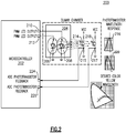
- a circuit 200 for monitoring and controlling the color generated by the tri-color LEDs 102 comprises a controller 202 (a microprocessor or microcontroller) having a "first" output terminal 210 electrically connected to the anode of the first color (e.g. red) LED 206 of a tri-color dummy LED 204.
- a second output terminal 212 is connected to the anode of a second color (e.g. green) LED 208 of the tri-color dummy LED 204.
- the tri-color dummy LED 204 is preferably located as close as possible to the phototransistors 214 and 218, the respective spectral sensitivities of which are respectively illustrated in accompanying graphs 216 and 220.
- the first output terminal 210 of the controller 202 is a pulse width modulated signal, the duty cycle of which is controlled by the controller 202 to effectively change the current provided to the corresponding LED.
- the second output terminal 212 is a pulse width modulated signal, the duty cycle of which is also controlled by the processor 202 to effectively change the current provided to the corresponding LED. Controlling the duty cycles of the signals provided to the LEDs 206 and 208 effectively controls the intensity of the light output from each LED and thus the color of the light emitted from the combination of the two colors emitted from the dummy LED.
- the signals output from the controller 202 to the LEDs 206 and 208 are adjusted until a desired combined color is created by (output from) the tri-color LED 204.
- the voltages output from the emitters 215, 217 of the phototransistors 214 and 218 at the desired or selected color are read or obtained by the controller through two corresponding input terminals 226 and 224.
- Analog-to-digital converters that are of course required to convert the analog voltages generated by the phtototransistors to a digital form are omitted from the figure in the interest of brevity.
- the first and second color e.g.
- the controller adjusts the signals provided to the red and green LEDs 206 and 208 to maintain the voltages output from the emitters 215, 217 of the corresponding phototransistors. Stated another way, the controller adjusts the duty cycle of the PWM to select the desired intensities of the light output from the first color LED 206 and the light output from the second color LED 208 to maintain a continuous and stable or precise color.
- the electrical current provided to the first color (e.g. red) LED and the second color (e.g. green) LED of each tri-color LED 102 is maintained in the same way. Since the tri-color LEDs 102 and the dummy LED 110 are selected from the same manufacturing lot, and the PWM and duty cycle are set as the dummy LEDs, the color generated by each of the LEDs 102 in each compartment 108 can be maintained at a substantially constant color and substantially constant intensity regardless of the temperature inside the motor vehicle and regardless of the age of the LEDs.
- the controller which is electrically coupled to both phototransistors 214 and 218 and electrically coupled to both LEDs 206 and 208, provides a first amount of current to the first color (e.g. red) LED and a second amount of current to the second color (e.g. green) LED.
- the processor measures the output voltages from both phototransistors.
- the processor changes at least one of the currents provided to the second color (e.g. green) LED and the first color (e.g. red) LED until the output voltages from the first and second phototransistors are substantially equal to previously-obtained output voltages from those same phototransistors.
- a method 400 of controlling the color generated by combining light emitted from two, differently-colored LEDs is shown.
- a first step 402 the current intensity provided to both LEDs is "swept" to obtain all possible combinations of combined colors.
- the output voltage from each phototransistor is measured and recorded and placed into a table.
- the voltages output from the phototransistors are interpolated and the corresponding current provided to each LED generated to obtain combinations of light intensities desired from the two different-colored LEDs. The steps of sweeping current intensities, measuring and recording output voltages and interpolating output voltages is repeated over time in order to maintain a calibrated color that will be generated from the two different color LEDs when combined.
Landscapes
- Engineering & Computer Science (AREA)
- Mechanical Engineering (AREA)
- Circuit Arrangement For Electric Light Sources In General (AREA)
- Led Devices (AREA)
Abstract
Description
- This disclosure relates to a system and a method for displaying information related to an automotive vehicle, in particular a system and method for generating color for an instrumentation panel.
- It is well-known that two primary colors can be combined to generate a new third color between the two primary colors. Primary-color LEDs can therefore be used to generate different colors in a vehicle instrumentation panel, which is also more commonly known as a dashboard. Unfortunately, the color output from an LED changes with age and temperature.
- An apparatus and method to generate a consistent color from the combination of two primary-colored LEDs would be an improvement over the prior art.
- The background description provided herein is for the purpose of generally presenting the context of the disclosure. Work of the presently named inventors, to the extent it is described in this background section, as well as aspects of the description that may not otherwise qualify as prior art at the time of filing, are neither expressly nor impliedly admitted as prior art against the present disclosure.
- One general aspect includes an apparatus for controlling the color generated by combining the light emitted from first and second differently-colored light emitting diodes (LEDs).
- The first LED generates a first nominal color having an intensity that varies responsive to the amount of current flowing through the first LED, the second LED generating a second and different nominal color, having an intensity, which varies responsive to the amount of current flowing through the second LED.
- The color of light generated by combining the first LED light and the second LED light together being a third color.
- The third color varies responsive to the intensities of the colors emitted from the first and second LEDs.
- The apparatus includes a first phototransistor optically coupled to the first and second LEDs.
- The first phototransistor has a first spectral sensitivity and generates an output voltage having a magnitude that varies responsive to the wavelength of light impinging on the first phototransistor from both LEDs.
- A second phototransistor optically coupled to the first and second LEDs, the second phototransistor having a second and different spectral sensitivity and generating an output voltage having a magnitude that varies responsive to the wavelength of light impinging on the second phototransistor from both LEDs.
- The magnitudes of the output voltages output from the first and second phototransistors for a particular wavelength of light impinging on the transistors are different.
- Another embodiment of the apparatus may further include a controller electrically coupled to both the first and second phototransistors and electrically coupled to both the first and second LEDs.
- Another embodiment of the apparatus may further include a non-transitive memory device coupled to the controller and storing program instructions.
- Another embodiment of the apparatus may further include instructions which when executed result in providing a first amount current to the first LED.
- Another embodiment of the apparatus may further include instructions which when executed result in a second amount current applied to the second LED.
- Another embodiment of the apparatus may further include instructions which when executed result in measuring a first output voltage from the first phototransistor.
- Another embodiment of the apparatus may further include instructions which when executed result in measuring a second output voltage from the second phototransistor.
- The apparatus may also include change at least one of the first amount current and the second amount current until the output voltage from the first phototransistor and output voltage from the second phototransistor are substantially equal to previously obtained first and second output voltage values.
- Another embodiment of the apparatus may further include where the first LED generates light that is a first color and where the second LED generates light that is a second and different color, the apparatus further including: a plurality of pairs of different color LEDs.
- Another embodiment of the apparatus may further include where the controller is coupled to and providing current to each first color LED and each second color LED of the plurality of pairs of LEDs.
- Another embodiment of the apparatus may further include where the current provided to each first color LED is substantially the same as the current provided to the first color LED and where the current provided to each second color LED is substantially the same as the current provided to the second color LED.
- A method of controlling the color generated by combining the light emitted from first and second differently-colored light emitting diodes (LEDs), the first LED generating a first nominal color having an intensity that varies responsive to the amount of current flowing through the first LED.
- The second LED generating a second and different nominal color than the first LED, having an intensity, which varies responsive to the amount of current flowing through the second LED,
- The color of light generated by combining the first LED's light and the second LED's light together being a third nominal color.
- The third nominal color may vary responsive to the intensities of the colors emitted from the first and second LEDs.
- Further embodiments of the method may include sweeping the current provided to each of the LEDs to obtain combinations of possible colors available by the light provided by combining light from both LEDs.
- Further embodiments of the method may include for each color obtained by sweeping the current provide to the LEDs, measuring and recording the output voltages from two phototransistors having different spectral sensitivities.
- Further embodiments of the method may include interpolating voltages output from the two phototransistors to obtain combinations of light colors and intensities output from the first and second LEDs that are required to generate a desired third color by combining the colors from the LEDs.
- Further embodiments of the method may include repeating the steps of sweeping, measuring, recording and interpolating at predetermined intervals over time to maintain a calibrated color that will be generated from the first and second LEDs.
- Other objects, features and characteristics of the present invention, as well as the methods of operation and the functions of the related elements of the structure, the combination of parts and economics of manufacture will become more apparent upon consideration of the following detailed description and appended claims with reference to the accompanying drawings, all of which form a part of this specification. It should be understood that the detailed description and specific examples, while indicating the preferred embodiment of the disclosure, are intended for purposes of illustration only and are not intended to limit the scope of the disclosure.
- The present disclosure will become more fully understood from the detailed description and the accompanying drawings, wherein:
-
FIG. 1 depicts a circuit board having multiple, tri-color LEDs that provide precise backlight illumination and which also has a "dummy" tri-color LED and two phototransistors that monitor the light that is output from the dummy LED; -
FIG. 2 depicts a schematic diagram of a circuit to monitor the colors of light that is output from two LEDs that comprise a tri-color LED and which can maintain color consistency; -
FIG. 3 is a table of relative colored light output from the two color LEDs of the dummy tri-color LED; and -
FIG. 4 depicts a method. - As used herein, the term "tri-color" LED refers to, two LEDs that have independent electrical connections (anode and cathode) or, a common cathode connection but in the same package, or two LEDs that are totally independent (different package and electrical connections). The two LEDs color could be red, green, blue or any color (e.g. green and red). By turning one or both LED on and varying the current provided to them, the color produced by their combined light output can be red, green, orange or yellow or other colors. To obtain a full range of colors a blue LED could be added to form an RGB LED, referred to herein as a multi-color LED.
-
FIG. 1 depicts anapparatus 100 for providing precise color backlight illumination to a motor vehicle dashboard. Theapparatus 100 comprises aconventional circuit board 104, attached to which areseveral tri-color LEDs 102. Thetri-color LEDs 102 are inside or surrounded by small,shallow compartments 108. Eachcompartment 108 is part of a plasticmulti-compartment frame 106, which is also attached to thecircuit board 104. - In the preferred embodiment, if the
tri-color LEDs 102 have a red LED and a green LED, the electrical connections (anode and cathode) can be independent to provide more flexibility to the circuit topology. The anode/cathode for the first color LED and the anode/cathode for the second color LED are electrically isolated from each other such that the LEDs can be energized separately. Providing a voltage to the first color LED anode will turn the first color LED on but will not turn on the second color LED. Similarly, providing a voltage to the second color LED anode will turn the second color LED on but will not turn on the first color LED. The intensity of the colors emitted from the LEDs can thus be varied with the amount of current passing through each LED. By adjusting the current through the two LEDs, the combination color emitted from them can thus be changed as shown in the color combination chart inFIG. 3 . - Those of ordinary skill in the art know that a phototransistor has a non-linear spectral sensitivity. In
FIG. 1 , thecircuit board 104 also supports a "dummy"LED 110 and twophototransistors dummy LED 110 and inside a second, substantiallycylindrical compartment 116. Thephototransistors compartment 116 are selected to have different spectral sensitivities, e.g., they generate output voltages that differ from each other when they are subject to the same color and same intensity light. The output voltages generated at their respective emitters will be different when they are exposed to the same light from thedummy LED 110. If thedummy tri-color LED 110 has the same or at least substantially the same electrical and physical characteristics of the tri-color LEDs in the compartments, the phototransistors' outputs can be used to "test" or monitor the color generated by thedummy LED 110 and thus provide signals by which the current provided to the constituent green and red LEDs can be adjusted over time in order to maintain the color output from thedummy LED 110 as well as themain tri-color LEDs 102. - Referring now to
FIG. 2 , acircuit 200 for monitoring and controlling the color generated by thetri-color LEDs 102 comprises a controller 202 (a microprocessor or microcontroller) having a "first"output terminal 210 electrically connected to the anode of the first color (e.g. red)LED 206 of atri-color dummy LED 204. Asecond output terminal 212 is connected to the anode of a second color (e.g. green)LED 208 of thetri-color dummy LED 204. - As shown in
FIG. 1 , thetri-color dummy LED 204 is preferably located as close as possible to thephototransistors graphs - In the preferred embodiment, the
first output terminal 210 of thecontroller 202 is a pulse width modulated signal, the duty cycle of which is controlled by thecontroller 202 to effectively change the current provided to the corresponding LED. Similarly, thesecond output terminal 212 is a pulse width modulated signal, the duty cycle of which is also controlled by theprocessor 202 to effectively change the current provided to the corresponding LED. Controlling the duty cycles of the signals provided to theLEDs - In the preferred embodiment, the signals output from the
controller 202 to theLEDs tri-color LED 204. The voltages output from theemitters phototransistors corresponding input terminals tri-color dummy LED 204 age and their output colors and intensity change, the controller adjusts the signals provided to the red andgreen LEDs emitters first color LED 206 and the light output from thesecond color LED 208 to maintain a continuous and stable or precise color. - In the same way, the electrical current provided to the first color (e.g. red) LED and the second color (e.g. green) LED of each
tri-color LED 102 is maintained in the same way. Since thetri-color LEDs 102 and thedummy LED 110 are selected from the same manufacturing lot, and the PWM and duty cycle are set as the dummy LEDs, the color generated by each of theLEDs 102 in eachcompartment 108 can be maintained at a substantially constant color and substantially constant intensity regardless of the temperature inside the motor vehicle and regardless of the age of the LEDs. - In the preferred embodiment, the controller, which is electrically coupled to both
phototransistors LEDs - Referring now to
FIG. 4 , amethod 400 of controlling the color generated by combining light emitted from two, differently-colored LEDs. - In a
first step 402, the current intensity provided to both LEDs is "swept" to obtain all possible combinations of combined colors. At asecond step 404, the output voltage from each phototransistor is measured and recorded and placed into a table. At athird step 406, the voltages output from the phototransistors are interpolated and the corresponding current provided to each LED generated to obtain combinations of light intensities desired from the two different-colored LEDs. The steps of sweeping current intensities, measuring and recording output voltages and interpolating output voltages is repeated over time in order to maintain a calibrated color that will be generated from the two different color LEDs when combined. - Those of ordinary skill in the art should recognize that the apparatus and method disclosed herein can work with any number of different color LEDs. Accordingly, the foregoing description is for purposes of illustration only. The true scope of the invention is set forth in the following claims.
- The foregoing preferred embodiments have been shown and described for the purposes of illustrating the structural and functional principles of the present invention, as well as illustrating the methods of employing the preferred embodiments and are subject to change without departing from such principles. Therefore, this invention includes all modifications encompassed within the scope of the following claims.
Claims (5)
- An apparatus (100) for controlling the color generated by combining the light emitted from first and second differently-colored light emitting diodes (LEDs), the first LED (206) generating a first nominal color having an intensity that varies responsive to the amount of current flowing through the first LED (206), the second LED (208) generating a second and different nominal color, having an intensity, which varies responsive to the amount of current flowing through the second LED (208), the color of light generated by combining the first LED's light and the second LED's light together being a third color, the third color varying responsive to the intensities of the colors emitted from the first and second LEDs (206, 208), the apparatus (100) comprising:a first phototransistor (214) optically coupled to the first and second LEDs, the first phototransistor (214) having a first spectral sensitivity and generating an output voltage having a magnitude that varies responsive to the wavelength of light impinging on the first phototransistor from both LEDs;a second phototransistor (218) optically coupled to the first and second LEDs, the second phototransistor (218) having a second and different spectral sensitivity and generating an output voltage having a magnitude that varies responsive to the wavelength of light impinging on the second phototransistor from both LEDs;wherein the magnitudes of the output voltages output from the first and second phototransistors (214, 218) for a particular wavelength of light impinging on the transistors are different.
- The apparatus of claim 1, further comprising:a controller (202) electrically coupled to both the first and second phototransistors (214, 218) and electrically coupled to both the first and second LEDs (206, 208);a non-transitive memory device coupled to the controller (202) and storing program instructions, which when executed cause the controller to:provide a first amount current to the first LED (206);provide a second amount current to the second LED (208);measure a first output voltage from the first phototransistor (214);measure a second output voltage from the second phototransistor (218);change at least one of the first amount current and the second amount current until the output voltage from the first phototransistor (214) and output voltage from the second phototransistor (218) are substantially equal to previously obtained first and second output voltage values.
- The apparatus (100) of claim 1, wherein the first LED (206) generates light that is a first color and wherein the second LED (208) generates light that is a second and different color, the apparatus (100) further comprising:a plurality of pairs of different color LEDs;wherein the controller (202) is coupled to and providing current to each first color LED and each second color LED of the plurality of pairs of LEDs;wherein the current provided to each first color LED is substantially the same as the current provided to the first color LED (206) and wherein the current provided to each second color LED is substantially the same as the current provided to the second color LED (208).
- A method of controlling the color generated by combining the light emitted from first and second differently-colored light emitting diodes (LEDs), the first LED (206) generating a first nominal color having an intensity that varies responsive to the amount of current flowing through the first LED (206), the second diode (208) generating a second and different nominal color, having an intensity, which varies responsive to the amount of current flowing through the second LED (208), the color of light generated by combining the first LED's light and the second LED's light together being a third nominal color, which varies responsive to the intensities of the colors emitted from the first and second LEDs (206, 208), the method comprising:sweeping the current provided to each of the LEDs (206, 208) to obtain combinations of possible colors available by the light provided by combining light from both LEDs (206, 208);for each color obtained by sweeping the current provide to the LEDs (206, 208), measuring and recording the output voltages from two phototransistors having different spectral sensitivities;interpolating voltages output from the two phototransistors to obtain combinations of light colors and intensities output from the first and second LEDs (206, 208) that are required to generate a desired third color by combining the colors from the LEDs.
- The method of claim 4, further comprising:
repeating the steps of sweeping, measuring, recording and interpolating at predetermined intervals over time to maintain a calibrated color that will be generated from the first and second LEDs (206, 208).
Applications Claiming Priority (1)
| Application Number | Priority Date | Filing Date | Title |
|---|---|---|---|
| US16/182,776 US10723263B2 (en) | 2018-11-07 | 2018-11-07 | Specific color generation with multicolor LED for precise color backlight illumination applications |
Publications (2)
| Publication Number | Publication Date |
|---|---|
| EP3651554A1 true EP3651554A1 (en) | 2020-05-13 |
| EP3651554B1 EP3651554B1 (en) | 2021-07-07 |
Family
ID=68424719
Family Applications (1)
| Application Number | Title | Priority Date | Filing Date |
|---|---|---|---|
| EP19206377.4A Active EP3651554B1 (en) | 2018-11-07 | 2019-10-30 | Specific color generation with multicolor led for precise color backlight illumination applications |
Country Status (2)
| Country | Link |
|---|---|
| US (1) | US10723263B2 (en) |
| EP (1) | EP3651554B1 (en) |
Citations (2)
| Publication number | Priority date | Publication date | Assignee | Title |
|---|---|---|---|---|
| US20020171373A1 (en) * | 2001-03-29 | 2002-11-21 | Koninklijke Philips Electronics N.V. | Controlling method and system for RGB based LED luminary |
| US20080077363A1 (en) * | 2006-09-26 | 2008-03-27 | Samsung Electronics Co., Ltd | Led-based optical system and method of compensating for aging thereof |
Family Cites Families (8)
| Publication number | Priority date | Publication date | Assignee | Title |
|---|---|---|---|---|
| US6513872B2 (en) | 2001-05-18 | 2003-02-04 | De Sede Ag | Multipart upholstered furniture |
| CN101213876A (en) * | 2005-06-30 | 2008-07-02 | 皇家飞利浦电子股份有限公司 | Method and system for controlling an output of a lighting device |
| CN101292574B (en) * | 2005-08-17 | 2012-12-26 | 皇家飞利浦电子股份有限公司 | Digitally controlled luminaire system |
| KR101300565B1 (en) * | 2005-10-26 | 2013-08-28 | 코닌클리즈케 필립스 일렉트로닉스 엔.브이. | Led luminary system |
| US7718942B2 (en) * | 2007-10-09 | 2010-05-18 | Avago Technologies Ecbu Ip (Singapore) Pte. Ltd. | Illumination and color management system |
| US8564205B2 (en) * | 2011-05-23 | 2013-10-22 | General Electric Company | Configurable vehicle solid state lighting |
| US9736895B1 (en) * | 2013-10-03 | 2017-08-15 | Ketra, Inc. | Color mixing optics for LED illumination device |
| JP2018501628A (en) * | 2015-01-13 | 2018-01-18 | フィリップス ライティング ホールディング ビー ヴィ | Operation of LED lighting elements controlled using light sensitive elements |
-
2018
- 2018-11-07 US US16/182,776 patent/US10723263B2/en active Active
-
2019
- 2019-10-30 EP EP19206377.4A patent/EP3651554B1/en active Active
Patent Citations (2)
| Publication number | Priority date | Publication date | Assignee | Title |
|---|---|---|---|---|
| US20020171373A1 (en) * | 2001-03-29 | 2002-11-21 | Koninklijke Philips Electronics N.V. | Controlling method and system for RGB based LED luminary |
| US20080077363A1 (en) * | 2006-09-26 | 2008-03-27 | Samsung Electronics Co., Ltd | Led-based optical system and method of compensating for aging thereof |
Also Published As
| Publication number | Publication date |
|---|---|
| EP3651554B1 (en) | 2021-07-07 |
| US10723263B2 (en) | 2020-07-28 |
| US20200139882A1 (en) | 2020-05-07 |
Similar Documents
| Publication | Publication Date | Title |
|---|---|---|
| USRE49479E1 (en) | LED illumination device and calibration method for accurately characterizing the emission LEDs and photodetector(s) included within the LED illumination device | |
| CN100490594C (en) | Red-green-blue-based light-emitting diode illuminant system | |
| US9510416B2 (en) | LED illumination device and method for accurately controlling the intensity and color point of the illumination device over time | |
| US9338851B2 (en) | Operation of a LED lighting system at a target output color using a color sensor | |
| US7718942B2 (en) | Illumination and color management system | |
| JP4589713B2 (en) | Light source control system adapted to reproduce the colors of known light sources | |
| US10652962B1 (en) | Dim-to-warm LED circuit | |
| KR101175806B1 (en) | Methods and apparatus for setting the color point of an led light source | |
| US7230222B2 (en) | Calibrated LED light module | |
| CN100410795C (en) | Pre-configured optical modules | |
| US9736903B2 (en) | Illumination device and method for calibrating and controlling an illumination device comprising a phosphor converted LED | |
| CN101352101A (en) | Method and apparatus for controlling a variable color light source | |
| US20110084615A1 (en) | Led assembly, led fixture, control method and software program | |
| EP3860312A1 (en) | Led illumination device and method for calibrating and controlling an led illumination device over changes in temperature, drive current, and time | |
| WO2007069149A1 (en) | Illumination device and method for controlling an illumination device | |
| US10492256B2 (en) | Method and device for calibrating LED lighting | |
| DE102013201915A1 (en) | Method and arrangement for controlling LEDs | |
| JP2006019263A (en) | Light source calibration | |
| US9097744B2 (en) | Method of determining PWM values for LED modules | |
| EP3651554B1 (en) | Specific color generation with multicolor led for precise color backlight illumination applications | |
| WO2016032772A1 (en) | Led illumination device and methods for accurately characterizing and controlling the emission leds and photodetector(s) included within the led illumination device | |
| US9723669B2 (en) | LED lighting system and controller, a method of controlling a plurality of LEDs, and a computer program therefor | |
| EP3991521B1 (en) | Dim-to-warm led circuit | |
| CA2848855C (en) | Operation of a led lighting system at a target output color using a color sensor | |
| US8519633B2 (en) | Method for producing a control device for operating a radiation-emitting semiconductor component |
Legal Events
| Date | Code | Title | Description |
|---|---|---|---|
| PUAI | Public reference made under article 153(3) epc to a published international application that has entered the european phase |
Free format text: ORIGINAL CODE: 0009012 |
|
| STAA | Information on the status of an ep patent application or granted ep patent |
Free format text: STATUS: THE APPLICATION HAS BEEN PUBLISHED |
|
| AK | Designated contracting states |
Kind code of ref document: A1 Designated state(s): AL AT BE BG CH CY CZ DE DK EE ES FI FR GB GR HR HU IE IS IT LI LT LU LV MC MK MT NL NO PL PT RO RS SE SI SK SM TR |
|
| AX | Request for extension of the european patent |
Extension state: BA ME |
|
| STAA | Information on the status of an ep patent application or granted ep patent |
Free format text: STATUS: REQUEST FOR EXAMINATION WAS MADE |
|
| 17P | Request for examination filed |
Effective date: 20201113 |
|
| RBV | Designated contracting states (corrected) |
Designated state(s): AL AT BE BG CH CY CZ DE DK EE ES FI FR GB GR HR HU IE IS IT LI LT LU LV MC MK MT NL NO PL PT RO RS SE SI SK SM TR |
|
| GRAP | Despatch of communication of intention to grant a patent |
Free format text: ORIGINAL CODE: EPIDOSNIGR1 |
|
| STAA | Information on the status of an ep patent application or granted ep patent |
Free format text: STATUS: GRANT OF PATENT IS INTENDED |
|
| INTG | Intention to grant announced |
Effective date: 20210323 |
|
| RIN1 | Information on inventor provided before grant (corrected) |
Inventor name: MORALES RODRIGUEZ, IRVING Inventor name: CORONA FRANCO ANTONIO DE JESUS Inventor name: FERNANDEZ MICHEL MARCELA Inventor name: RICHARDT-OSUNA, JOSE FRANCISCO |
|
| GRAS | Grant fee paid |
Free format text: ORIGINAL CODE: EPIDOSNIGR3 |
|
| GRAA | (expected) grant |
Free format text: ORIGINAL CODE: 0009210 |
|
| STAA | Information on the status of an ep patent application or granted ep patent |
Free format text: STATUS: THE PATENT HAS BEEN GRANTED |
|
| AK | Designated contracting states |
Kind code of ref document: B1 Designated state(s): AL AT BE BG CH CY CZ DE DK EE ES FI FR GB GR HR HU IE IS IT LI LT LU LV MC MK MT NL NO PL PT RO RS SE SI SK SM TR |
|
| REG | Reference to a national code |
Ref country code: GB Ref legal event code: FG4D |
|
| REG | Reference to a national code |
Ref country code: AT Ref legal event code: REF Ref document number: 1409902 Country of ref document: AT Kind code of ref document: T Effective date: 20210715 |
|
| REG | Reference to a national code |
Ref country code: DE Ref legal event code: R096 Ref document number: 602019005925 Country of ref document: DE |
|
| REG | Reference to a national code |
Ref country code: IE Ref legal event code: FG4D |
|
| REG | Reference to a national code |
Ref country code: NL Ref legal event code: FP |
|
| REG | Reference to a national code |
Ref country code: SE Ref legal event code: TRGR |
|
| REG | Reference to a national code |
Ref country code: LT Ref legal event code: MG9D |
|
| REG | Reference to a national code |
Ref country code: AT Ref legal event code: MK05 Ref document number: 1409902 Country of ref document: AT Kind code of ref document: T Effective date: 20210707 |
|
| PG25 | Lapsed in a contracting state [announced via postgrant information from national office to epo] |
Ref country code: PT Free format text: LAPSE BECAUSE OF FAILURE TO SUBMIT A TRANSLATION OF THE DESCRIPTION OR TO PAY THE FEE WITHIN THE PRESCRIBED TIME-LIMIT Effective date: 20211108 Ref country code: NO Free format text: LAPSE BECAUSE OF FAILURE TO SUBMIT A TRANSLATION OF THE DESCRIPTION OR TO PAY THE FEE WITHIN THE PRESCRIBED TIME-LIMIT Effective date: 20211007 Ref country code: FI Free format text: LAPSE BECAUSE OF FAILURE TO SUBMIT A TRANSLATION OF THE DESCRIPTION OR TO PAY THE FEE WITHIN THE PRESCRIBED TIME-LIMIT Effective date: 20210707 Ref country code: HR Free format text: LAPSE BECAUSE OF FAILURE TO SUBMIT A TRANSLATION OF THE DESCRIPTION OR TO PAY THE FEE WITHIN THE PRESCRIBED TIME-LIMIT Effective date: 20210707 Ref country code: BG Free format text: LAPSE BECAUSE OF FAILURE TO SUBMIT A TRANSLATION OF THE DESCRIPTION OR TO PAY THE FEE WITHIN THE PRESCRIBED TIME-LIMIT Effective date: 20211007 Ref country code: AT Free format text: LAPSE BECAUSE OF FAILURE TO SUBMIT A TRANSLATION OF THE DESCRIPTION OR TO PAY THE FEE WITHIN THE PRESCRIBED TIME-LIMIT Effective date: 20210707 Ref country code: LT Free format text: LAPSE BECAUSE OF FAILURE TO SUBMIT A TRANSLATION OF THE DESCRIPTION OR TO PAY THE FEE WITHIN THE PRESCRIBED TIME-LIMIT Effective date: 20210707 Ref country code: ES Free format text: LAPSE BECAUSE OF FAILURE TO SUBMIT A TRANSLATION OF THE DESCRIPTION OR TO PAY THE FEE WITHIN THE PRESCRIBED TIME-LIMIT Effective date: 20210707 Ref country code: RS Free format text: LAPSE BECAUSE OF FAILURE TO SUBMIT A TRANSLATION OF THE DESCRIPTION OR TO PAY THE FEE WITHIN THE PRESCRIBED TIME-LIMIT Effective date: 20210707 |
|
| PG25 | Lapsed in a contracting state [announced via postgrant information from national office to epo] |
Ref country code: PL Free format text: LAPSE BECAUSE OF FAILURE TO SUBMIT A TRANSLATION OF THE DESCRIPTION OR TO PAY THE FEE WITHIN THE PRESCRIBED TIME-LIMIT Effective date: 20210707 Ref country code: LV Free format text: LAPSE BECAUSE OF FAILURE TO SUBMIT A TRANSLATION OF THE DESCRIPTION OR TO PAY THE FEE WITHIN THE PRESCRIBED TIME-LIMIT Effective date: 20210707 Ref country code: GR Free format text: LAPSE BECAUSE OF FAILURE TO SUBMIT A TRANSLATION OF THE DESCRIPTION OR TO PAY THE FEE WITHIN THE PRESCRIBED TIME-LIMIT Effective date: 20211008 |
|
| REG | Reference to a national code |
Ref country code: DE Ref legal event code: R097 Ref document number: 602019005925 Country of ref document: DE |
|
| PG25 | Lapsed in a contracting state [announced via postgrant information from national office to epo] |
Ref country code: DK Free format text: LAPSE BECAUSE OF FAILURE TO SUBMIT A TRANSLATION OF THE DESCRIPTION OR TO PAY THE FEE WITHIN THE PRESCRIBED TIME-LIMIT Effective date: 20210707 |
|
| PLBE | No opposition filed within time limit |
Free format text: ORIGINAL CODE: 0009261 |
|
| STAA | Information on the status of an ep patent application or granted ep patent |
Free format text: STATUS: NO OPPOSITION FILED WITHIN TIME LIMIT |
|
| PG25 | Lapsed in a contracting state [announced via postgrant information from national office to epo] |
Ref country code: SM Free format text: LAPSE BECAUSE OF FAILURE TO SUBMIT A TRANSLATION OF THE DESCRIPTION OR TO PAY THE FEE WITHIN THE PRESCRIBED TIME-LIMIT Effective date: 20210707 Ref country code: SK Free format text: LAPSE BECAUSE OF FAILURE TO SUBMIT A TRANSLATION OF THE DESCRIPTION OR TO PAY THE FEE WITHIN THE PRESCRIBED TIME-LIMIT Effective date: 20210707 Ref country code: RO Free format text: LAPSE BECAUSE OF FAILURE TO SUBMIT A TRANSLATION OF THE DESCRIPTION OR TO PAY THE FEE WITHIN THE PRESCRIBED TIME-LIMIT Effective date: 20210707 Ref country code: EE Free format text: LAPSE BECAUSE OF FAILURE TO SUBMIT A TRANSLATION OF THE DESCRIPTION OR TO PAY THE FEE WITHIN THE PRESCRIBED TIME-LIMIT Effective date: 20210707 Ref country code: CZ Free format text: LAPSE BECAUSE OF FAILURE TO SUBMIT A TRANSLATION OF THE DESCRIPTION OR TO PAY THE FEE WITHIN THE PRESCRIBED TIME-LIMIT Effective date: 20210707 Ref country code: AL Free format text: LAPSE BECAUSE OF FAILURE TO SUBMIT A TRANSLATION OF THE DESCRIPTION OR TO PAY THE FEE WITHIN THE PRESCRIBED TIME-LIMIT Effective date: 20210707 |
|
| 26N | No opposition filed |
Effective date: 20220408 |
|
| REG | Reference to a national code |
Ref country code: BE Ref legal event code: MM Effective date: 20211031 |
|
| PG25 | Lapsed in a contracting state [announced via postgrant information from national office to epo] |
Ref country code: MC Free format text: LAPSE BECAUSE OF FAILURE TO SUBMIT A TRANSLATION OF THE DESCRIPTION OR TO PAY THE FEE WITHIN THE PRESCRIBED TIME-LIMIT Effective date: 20210707 |
|
| PG25 | Lapsed in a contracting state [announced via postgrant information from national office to epo] |
Ref country code: LU Free format text: LAPSE BECAUSE OF NON-PAYMENT OF DUE FEES Effective date: 20211030 Ref country code: IT Free format text: LAPSE BECAUSE OF FAILURE TO SUBMIT A TRANSLATION OF THE DESCRIPTION OR TO PAY THE FEE WITHIN THE PRESCRIBED TIME-LIMIT Effective date: 20210707 Ref country code: BE Free format text: LAPSE BECAUSE OF NON-PAYMENT OF DUE FEES Effective date: 20211031 |
|
| REG | Reference to a national code |
Ref country code: DE Ref legal event code: R081 Ref document number: 602019005925 Country of ref document: DE Owner name: CONTINENTAL AUTOMOTIVE TECHNOLOGIES GMBH, DE Free format text: FORMER OWNER: CONTINENTAL AUTOMOTIVE GMBH, 30165 HANNOVER, DE Ref country code: DE Ref legal event code: R081 Ref document number: 602019005925 Country of ref document: DE Owner name: AUMOVIO GERMANY GMBH, DE Free format text: FORMER OWNER: CONTINENTAL AUTOMOTIVE GMBH, 30165 HANNOVER, DE |
|
| PG25 | Lapsed in a contracting state [announced via postgrant information from national office to epo] |
Ref country code: FR Free format text: LAPSE BECAUSE OF NON-PAYMENT OF DUE FEES Effective date: 20211031 |
|
| PG25 | Lapsed in a contracting state [announced via postgrant information from national office to epo] |
Ref country code: IE Free format text: LAPSE BECAUSE OF NON-PAYMENT OF DUE FEES Effective date: 20211030 |
|
| REG | Reference to a national code |
Ref country code: CH Ref legal event code: PL |
|
| P01 | Opt-out of the competence of the unified patent court (upc) registered |
Effective date: 20230522 |
|
| PG25 | Lapsed in a contracting state [announced via postgrant information from national office to epo] |
Ref country code: CY Free format text: LAPSE BECAUSE OF FAILURE TO SUBMIT A TRANSLATION OF THE DESCRIPTION OR TO PAY THE FEE WITHIN THE PRESCRIBED TIME-LIMIT Effective date: 20210707 |
|
| PG25 | Lapsed in a contracting state [announced via postgrant information from national office to epo] |
Ref country code: LI Free format text: LAPSE BECAUSE OF NON-PAYMENT OF DUE FEES Effective date: 20221031 Ref country code: HU Free format text: LAPSE BECAUSE OF FAILURE TO SUBMIT A TRANSLATION OF THE DESCRIPTION OR TO PAY THE FEE WITHIN THE PRESCRIBED TIME-LIMIT; INVALID AB INITIO Effective date: 20191030 Ref country code: CH Free format text: LAPSE BECAUSE OF NON-PAYMENT OF DUE FEES Effective date: 20221031 |
|
| REG | Reference to a national code |
Ref country code: DE Ref legal event code: R081 Ref document number: 602019005925 Country of ref document: DE Owner name: CONTINENTAL AUTOMOTIVE TECHNOLOGIES GMBH, DE Free format text: FORMER OWNER: CONTINENTAL AUTOMOTIVE TECHNOLOGIES GMBH, 30165 HANNOVER, DE Ref country code: DE Ref legal event code: R081 Ref document number: 602019005925 Country of ref document: DE Owner name: AUMOVIO GERMANY GMBH, DE Free format text: FORMER OWNER: CONTINENTAL AUTOMOTIVE TECHNOLOGIES GMBH, 30165 HANNOVER, DE |
|
| PG25 | Lapsed in a contracting state [announced via postgrant information from national office to epo] |
Ref country code: MK Free format text: LAPSE BECAUSE OF FAILURE TO SUBMIT A TRANSLATION OF THE DESCRIPTION OR TO PAY THE FEE WITHIN THE PRESCRIBED TIME-LIMIT Effective date: 20210707 |
|
| GBPC | Gb: european patent ceased through non-payment of renewal fee |
Effective date: 20231030 |
|
| PG25 | Lapsed in a contracting state [announced via postgrant information from national office to epo] |
Ref country code: TR Free format text: LAPSE BECAUSE OF FAILURE TO SUBMIT A TRANSLATION OF THE DESCRIPTION OR TO PAY THE FEE WITHIN THE PRESCRIBED TIME-LIMIT Effective date: 20210707 |
|
| PG25 | Lapsed in a contracting state [announced via postgrant information from national office to epo] |
Ref country code: GB Free format text: LAPSE BECAUSE OF NON-PAYMENT OF DUE FEES Effective date: 20231030 |
|
| PG25 | Lapsed in a contracting state [announced via postgrant information from national office to epo] |
Ref country code: GB Free format text: LAPSE BECAUSE OF NON-PAYMENT OF DUE FEES Effective date: 20231030 |
|
| PG25 | Lapsed in a contracting state [announced via postgrant information from national office to epo] |
Ref country code: MT Free format text: LAPSE BECAUSE OF FAILURE TO SUBMIT A TRANSLATION OF THE DESCRIPTION OR TO PAY THE FEE WITHIN THE PRESCRIBED TIME-LIMIT Effective date: 20210707 |
|
| PGFP | Annual fee paid to national office [announced via postgrant information from national office to epo] |
Ref country code: NL Payment date: 20251029 Year of fee payment: 7 |
|
| PGFP | Annual fee paid to national office [announced via postgrant information from national office to epo] |
Ref country code: DE Payment date: 20251031 Year of fee payment: 7 |
|
| PGFP | Annual fee paid to national office [announced via postgrant information from national office to epo] |
Ref country code: SE Payment date: 20251024 Year of fee payment: 7 |
|
| REG | Reference to a national code |
Ref country code: DE Ref legal event code: R081 Ref document number: 602019005925 Country of ref document: DE Owner name: AUMOVIO GERMANY GMBH, DE Free format text: FORMER OWNER: CONTINENTAL AUTOMOTIVE TECHNOLOGIES GMBH, 30175 HANNOVER, DE |