EP3651501B1 - Wireless communication method and wireless communication device - Google Patents
Wireless communication method and wireless communication device Download PDFInfo
- Publication number
- EP3651501B1 EP3651501B1 EP18828089.5A EP18828089A EP3651501B1 EP 3651501 B1 EP3651501 B1 EP 3651501B1 EP 18828089 A EP18828089 A EP 18828089A EP 3651501 B1 EP3651501 B1 EP 3651501B1
- Authority
- EP
- European Patent Office
- Prior art keywords
- user equipment
- subchannel
- base station
- signature domain
- terminal device
- Prior art date
- Legal status (The legal status is an assumption and is not a legal conclusion. Google has not performed a legal analysis and makes no representation as to the accuracy of the status listed.)
- Not-in-force
Links
- 238000004891 communication Methods 0.000 title claims description 55
- 238000000034 method Methods 0.000 title claims description 26
- 230000005540 biological transmission Effects 0.000 claims description 38
- 238000012545 processing Methods 0.000 claims description 10
- 230000008569 process Effects 0.000 description 20
- 230000006870 function Effects 0.000 description 13
- 238000010586 diagram Methods 0.000 description 10
- 238000005516 engineering process Methods 0.000 description 5
- 230000000737 periodic effect Effects 0.000 description 5
- 230000003993 interaction Effects 0.000 description 4
- 239000004065 semiconductor Substances 0.000 description 4
- 230000011664 signaling Effects 0.000 description 4
- 230000008901 benefit Effects 0.000 description 3
- 230000010267 cellular communication Effects 0.000 description 3
- 230000007246 mechanism Effects 0.000 description 2
- 230000003287 optical effect Effects 0.000 description 2
- 230000002441 reversible effect Effects 0.000 description 2
- 230000005236 sound signal Effects 0.000 description 2
- 230000003595 spectral effect Effects 0.000 description 2
- 238000012546 transfer Methods 0.000 description 2
- 230000001133 acceleration Effects 0.000 description 1
- 230000000295 complement effect Effects 0.000 description 1
- 238000013461 design Methods 0.000 description 1
- 238000011161 development Methods 0.000 description 1
- 230000000694 effects Effects 0.000 description 1
- 239000004973 liquid crystal related substance Substances 0.000 description 1
- 230000007774 longterm Effects 0.000 description 1
- 238000005259 measurement Methods 0.000 description 1
- 229910044991 metal oxide Inorganic materials 0.000 description 1
- 150000004706 metal oxides Chemical class 0.000 description 1
- 238000012986 modification Methods 0.000 description 1
- 230000004048 modification Effects 0.000 description 1
- 230000008054 signal transmission Effects 0.000 description 1
- 238000001228 spectrum Methods 0.000 description 1
- 230000002123 temporal effect Effects 0.000 description 1
Images




Classifications
-
- H—ELECTRICITY
- H04—ELECTRIC COMMUNICATION TECHNIQUE
- H04W—WIRELESS COMMUNICATION NETWORKS
- H04W74/00—Wireless channel access
- H04W74/002—Transmission of channel access control information
-
- H—ELECTRICITY
- H04—ELECTRIC COMMUNICATION TECHNIQUE
- H04W—WIRELESS COMMUNICATION NETWORKS
- H04W74/00—Wireless channel access
- H04W74/08—Non-scheduled access, e.g. ALOHA
- H04W74/0808—Non-scheduled access, e.g. ALOHA using carrier sensing, e.g. carrier sense multiple access [CSMA]
-
- H—ELECTRICITY
- H04—ELECTRIC COMMUNICATION TECHNIQUE
- H04W—WIRELESS COMMUNICATION NETWORKS
- H04W72/00—Local resource management
- H04W72/30—Resource management for broadcast services
-
- H—ELECTRICITY
- H04—ELECTRIC COMMUNICATION TECHNIQUE
- H04W—WIRELESS COMMUNICATION NETWORKS
- H04W16/00—Network planning, e.g. coverage or traffic planning tools; Network deployment, e.g. resource partitioning or cells structures
- H04W16/14—Spectrum sharing arrangements between different networks
-
- H—ELECTRICITY
- H04—ELECTRIC COMMUNICATION TECHNIQUE
- H04W—WIRELESS COMMUNICATION NETWORKS
- H04W48/00—Access restriction; Network selection; Access point selection
- H04W48/08—Access restriction or access information delivery, e.g. discovery data delivery
- H04W48/10—Access restriction or access information delivery, e.g. discovery data delivery using broadcasted information
-
- H—ELECTRICITY
- H04—ELECTRIC COMMUNICATION TECHNIQUE
- H04W—WIRELESS COMMUNICATION NETWORKS
- H04W72/00—Local resource management
- H04W72/02—Selection of wireless resources by user or terminal
-
- H—ELECTRICITY
- H04—ELECTRIC COMMUNICATION TECHNIQUE
- H04W—WIRELESS COMMUNICATION NETWORKS
- H04W72/00—Local resource management
- H04W72/04—Wireless resource allocation
- H04W72/044—Wireless resource allocation based on the type of the allocated resource
-
- H—ELECTRICITY
- H04—ELECTRIC COMMUNICATION TECHNIQUE
- H04W—WIRELESS COMMUNICATION NETWORKS
- H04W72/00—Local resource management
- H04W72/04—Wireless resource allocation
- H04W72/044—Wireless resource allocation based on the type of the allocated resource
- H04W72/0446—Resources in time domain, e.g. slots or frames
-
- H—ELECTRICITY
- H04—ELECTRIC COMMUNICATION TECHNIQUE
- H04W—WIRELESS COMMUNICATION NETWORKS
- H04W74/00—Wireless channel access
- H04W74/002—Transmission of channel access control information
- H04W74/004—Transmission of channel access control information in the uplink, i.e. towards network
Definitions
- the present disclosure relates to a terminal device, to a base station and to respective communication methods for implementing non-orthogonal multiple access in an unlicensed frequency band.
- non-orthogonal multiple access (NOMA) technology is a very promising multiple access technology.
- NOMA orthogonal multiple access
- OMA orthogonal multiple access
- one transmission resource for example, a frequency resource or a time resource
- NOMA technology one resource may be allocated to multiple user equipments.
- the basic concept of the NOMA is that non-orthogonal transmission is performed at the transmitting end and interference information is introduced initiatively, and serial interference cancellation is performed at the receiving end to implement correct demodulation. Therefore, compared with the conventional OMA, the NOMA has a higher spectral efficiency and user fairness.
- multiple access (MA) signatures are used at the transmitting end to distinguish the user equipments from one another, that is, each user equipment transmits signals by using a unique MA signature.
- the MA signature may be, for example, in the form of a codebook, a sequence, and the like.
- the NOMA may be supported by 5G new radio (NR), that is, multiple user equipments may transmit uplink signals by using the same resource block.
- NR 5G new radio
- LBT Listen Before Talk
- FIG. 1A schematically shows a process performed by a user equipment according to the present disclosure.
- the user equipment UE detects broadcast information on one or more subchannels in an unlicensed frequency band in step S10. Then in step S20, for a certain subchannel, the user equipment UE determines that the broadcast information is not successfully detected.
- the broadcast information is detected successfully indicates a case where there is broadcast information on the subchannel and the user equipment successfully decodes the broadcast information
- the broadcast information is not detected successfully indicates a case where there is no broadcast information on the subchannel and a case where there is broadcast information on the subchannel but the user equipment cannot successfully decode the broadcast information.
- the user equipment UE may determine, in step S30, that it is the first device accessing the subchannel and thus broadcast information on the subchannel.
- the broadcasted information includes an end time for occupation of the subchannel by the user equipment UE.
- Figure 1B shows a detailed process performed by a user equipment according to a first embodiment of the present disclosure.
- the user equipment UE selects one or more subchannels in the unlicensed frequency band, and detects the broadcast information on the selected subchannels, as shown in step S110.
- the user equipment UE randomly selects one or more subchannels in the unlicensed frequency band.
- the subchannel is not selected by the user equipment UE, but semi-statically allocated to the user equipment UE by a base station.
- the user equipment UE may further determine whether the subchannel is idle, and the process proceeds to step S130.
- step S130 the user equipment UE performs "Listen Before Talk” (LBT) to determine whether the subchannel is idle. For example, the user equipment UE may determine whether the subchannel is idle by detecting signal energy on the subchannel. In a case that it is determined in step S140 that the subchannel is idle (for example, the signal energy is lower than a certain threshold), the process proceeds to step S150.
- LBT Listen Before Talk
- the user equipment UE performs broadcasting on the subchannel, and the broadcasted information includes an end time for a time period during which the user equipment UE can occupy the subchannel.
- the end time may be indicated by an end time point, an end subframe, an end symbol, or the like.
- the information broadcasted by the user equipment UE may include an access time and a maximum channel occupation time (MCOT) for the user equipment UE.
- MCOT maximum channel occupation time
- other user equipments that receive the broadcast information may determine the end time for occupation of the subchannel by the user equipment UE according to the broadcast information.
- the user equipment UE may periodically broadcast the end time on the subchannel prior to the end time.
- the user equipment further selects a certain MA signature from a MA signature resource pool, and transmits a signal to the base station on the subchannel by using the selected MA signature.
- the user equipment UE may arbitrarily select a MA signature from the MA signature resource pool to perform signal transmission.
- the user equipment UE determines in step S140 that the subchannel is not idle (for example, the signal energy is higher than a certain threshold), it means that there is a signal transmitted by another user equipment on the subchannel. As an example, there may be a signal broadcasted by another user equipment on the subchannel that the user equipment UE cannot decode. Since the subchannel is already occupied by other user equipment, the user equipment UE cannot access the subchannel. Therefore, the process returns to step S130, and the user equipment UE continues to perform "Listen Before Talk" (LBT).
- LBT Listen Before Talk
- step S120 determines in step S120 that the broadcast information is successfully detected on the subchannel (including successfully decoding the broadcast information), although it means that another user equipment already occupies the subchannel, the user equipment UE may access the subchannel. Therefore, the process proceeds to step S160.
- the user equipment UE obtains the available MA signatures on the subchannel by decoding the broadcast information from the base station.
- the base station may broadcast the available MA signatures on the subchannel in a licensed frequency band. Further, the base station may periodically broadcast the available MA signatures.
- step S170 the user equipment UE selects one MA signature from the obtained available MA signatures to perform uplink transmission on the subchannel.
- the user equipment UE which is the first user equipment accessing a certain subchannel in the unlicensed frequency band, performs broadcasting. Any other user equipment that intends to access the subchannel may determine that it can access the subchannel when it successfully decodes the broadcast information of the user equipment UE. Subsequently, the other user equipment may perform uplink transmission on the subchannel by obtaining the MA signature from the base station, that is, the other user equipment shares the subchannel with the user equipment UE. In this way, uplink non-orthogonal multiple access in the unlicensed frequency band is realized. On the contrary, if the other user equipment that intends to access the subchannel cannot successfully decode the broadcast information of the user equipment UE, the other user equipment cannot access the subchannel, according to the conventional Listen Before Talk mechanism.
- the broadcast information transmitted by the user equipment UE may only be decoded by another user equipment belonging to the same system, thus the user equipment belonging to the same system as the user equipment UE may be allowed to access the subchannel and share the subchannel with the user equipment UE, thereby improving spectrum efficiency.
- Another user equipment belonging to a different system from the user equipment UE cannot access the subchannel because it cannot decode the broadcast signal.
- the user equipments preferably, for the user equipments belonging to respective systems that intend to occupy the subchannel, the user equipments have uniform maximum channel occupation time so as to ensure fairness in coexistence of the respective systems.
- the systems herein may include an NR system and a WiFi system.
- the maximum number of user equipments performing transmission on the same subchannel may be controlled by adjusting the broadcast power of the user equipment UE.
- the broadcast power may be determined based on a communication scenario. For example, in a large-scale machine type communication (mMTC) scenario, the broadcast power may be set to be higher so that more user equipments may share the same subchannel. In an ultra-high reliable low latency communication (URLLC) scenario, the broadcast power may be set to be lower to limit the number of user equipments sharing the subchannel, thereby ensuring the reliability of communication.
- mMTC large-scale machine type communication
- URLLC ultra-high reliable low latency communication
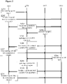
- Figure 2 is a diagram showing signaling interaction between a user equipment and a base station according to a first embodiment of the present disclosure.
- the user equipment UE1 is determined to be the first user equipment accessing a certain subchannel in the unlicensed frequency band according to the process in Figure 1 , and the user equipments UE2 and UE3 may access the subchannel following the user equipment UE1.
- the user equipment UE1 transmits an uplink signal to the base station gNB by using a certain MA signature on the subchannel after determining that it is the first user equipment occupying the subchannel, as shown in step S201.
- the user equipment UE1 performs broadcasting on the subchannel in step S202, and the broadcasted information includes the end time for occupation of the subchannel by the user equipment UE1.
- the broadcasted information may include the access time and maximum channel occupation time period of the user equipment UE1. It should be noted that steps S201 and S202 are not necessarily performed in the order shown in Figure 2 , but may be performed in a reverse order or simultaneously.
- the base station gNB may obtain the MA signature used by the user equipment UE1 by receiving the uplink signal from the user equipment UE1, and the base station gNB determines the available MA signatures by excluding the MA signature used by the user equipment UE1 from the MA signature resource pool.
- the base station gNB broadcasts the determined available MA signatures to each user equipment in step S203.
- the user equipment UE2 In a case that the user equipment UE2 successfully detects the broadcast information of the user equipment UE1 and determines that it may access the subchannel, the user equipment UE2 obtains the available MA signatures on the subchannel by receiving the broadcast information from the base station, and selects one MA signature from the obtained available MA signatures to perform uplink transmission, as shown in step S204.
- the base station gNB may obtain the MA signature used by the user equipment UE2 by receiving signal from the user equipment UE2, and update the available MA signatures by excluding the MA signature used by the user equipment UE2 from the available MA signatures, as shown in step S205. Subsequently, the base station gNB broadcasts the updated available MA signatures to each user equipment in step S206.
- the user equipment UE1 may periodically broadcast the end time on the subchannel, as shown in step S207.
- the user equipment UE3 obtains the current available MA signatures on the subchannel by decoding the broadcast information from the base station, and selects one MA signature from the available MA signatures to perform uplink transmission, as shown in step S208.
- the base station gNB may determine the MA signature used by the user equipment UE3 by receiving signal from the user equipment UE3, and update the available MA signatures again by excluding the MA signature used by the user equipment UE3 from the available MA signatures, as shown in step S209. Subsequently, the base station gNB broadcasts the updated available MA signatures to each user equipment in step S210.
- the base station gNB may broadcast the MA signatures available on the subchannel in a licensed frequency band, for example, via Physical Broadcast Channel (PBCH).
- PBCH Physical Broadcast Channel
- step S211 since the user equipment UE1 periodically broadcasts the end time for occupation on the subchannel, it is indicated in step S211 that the user equipment UE1 broadcasts the end time again.
- the user equipment UE1 may periodically broadcast the end time for occupation of the channel, and the base station gNB may periodically update the available MA signatures and broadcast the updated available MA signatures to each user equipment.
- the periodic operations of the user equipment UE1 and the base station gNB are independent from each other, and may have different periodicities.
- Figure 2 shows that the user equipment UE1 broadcasts the end time for occupation again (step S207) after the base station broadcasts the updated available MA signatures (step S206), the present disclosure is not limited thereto. That is, step S207 and the step performed by the base station gNB are performed in a random order.
- the temporal relationship between the periodic broadcasting of the user equipment UE1 and the periodic updating of the base station gNB is not limited in the present disclosure.
- Figure 2 shows the base station gNB updates the available MA signatures each time receiving the uplink signals from the user equipments (UE2, UE3)
- the present disclosure is not limited thereto.
- the base station gNB may not update the available MA signatures for each reception of an uplink signal, and instead updates the available MA signatures with a longer periodicity.
- Figure 3 shows a process performed by a user equipment according to a second embodiment of the present disclosure.
- the user equipment UE selects one or more subchannels in the unlicensed frequency band, and detects broadcast information on the selected subchannels, as shown in step S310.
- the user equipment UE may randomly select a subchannel, or the base station may semi-statically allocate a subchannel to the user equipment UE.
- step S320 the user equipment UE determines in step S320 that the broadcast information is not successfully detected on the subchannel, the user equipment may further determine whether the subchannel is idle. Therefore, the process proceeds to step S330.
- step S330 the user equipment UE performs "Listen Before Talk" to determine whether the subchannel is idle.
- the user equipment UE may determine whether the subchannel is idle by detecting signal energy on the subchannel. In a case that it is determined in step S340 that the subchannel is idle (for example, the signal energy is lower than a certain threshold), the process of the user equipment UE proceeds to step S350.
- the user equipment UE performs broadcasting on the subchannel, and the broadcasted information may include an end time for occupation of the subchannel by the user equipment UE, or an access time and a maximum channel occupation time of the user equipment UE.
- the user equipment UE selects a certain MA signature from the MA signature pool, and performs uplink transmission on the subchannel with the selected MA signature.
- the user equipment UE since the user equipment UE is the first user equipment accessing the subchannel, the user equipment UE may arbitrarily select a MA signature from the MA signature pool. The process is the same as that in the first embodiment.
- the user equipment UE which is the first user equipment accessing the subchannel, further broadcasts the current available MA signatures on the subchannel in step S350, and the current available MA signatures may be obtained by excluding the MA signature selected by the user equipment UE from the MA signature pool.
- the available MA signatures may be notified by the base station. In this case, the base station periodically updates the available MA signatures and notifies the user equipment UE of the updated signature, and the user equipment UE periodically broadcasts the current available MA signatures on the subchannel.
- the user equipment UE determines in step S340 that the subchannel is not idle (for example, the signal energy is higher than a certain threshold), it means that there is a signal transmitted by another user equipment on the subchannel. As an example, there may be a signal broadcasted by another user equipment on the subchannel that the user equipment UE cannot decode. Since the subchannel is already occupied by the other user equipment, the user equipment UE cannot access the subchannel. Therefore, the process returns to step S330, and the user equipment UE continues to perform "Listen Before Talk".
- step S320 determines in step S320 that the broadcast information is successfully detected (decoded) on the subchannel, although it means that another user equipment already performs transmission on the subchannel, the user equipment UE determines that it can also access the subchannel. Therefore, the process proceeds to step S360.
- the user equipment UE may obtain the current available MA signatures by decoding the broadcast information. As such, in step S360, the user equipment UE selects one MA signature from the obtained available MA signatures to perform uplink transmission.
- the user equipment UE which is the first user equipment occupying the subchannel, performs broadcasting on the subchannel, and any other user equipment that intends to access the subchannel can access the subchannel if it successfully decodes the broadcast information of the user equipment UE, that is, the other user equipment can share the subchannel with the user equipment UE. Therefore, the uplink non-orthogonal multiple access in the unlicensed frequency band is realized. On the contrary, any other user equipment that intends to access the subchannel cannot access the subchannel if it cannot successfully decode the broadcast information.
- Figure 4 shows a diagram of signaling interaction between a user equipment and a base station according to a second embodiment of the present disclosure.
- the user equipment UE1 is the first user equipment occupying a certain subchannel in the unlicensed frequency band, and the user equipments UE2 and UE3 may access the subchannel following the user equipment UE1.
- the user equipment UE1 which is the first user equipment occupying the subchannel, transmits an uplink signal to the base station gNB by using the MA signature selected from the MA signature resource pool in step S401.
- the user equipment UE1 performs broadcasting on the subchannel in step S402, the broadcasted information includes the end time for occupation of the user equipment UE1 and MA signatures available on the subchannel.
- the broadcasted available MA signatures are determined by the user equipment UE1 by excluding the selected MA signature from the MA signature resource pool. It should be noted that steps S401 and S402 are not necessarily performed in the order shown in Figure 4 , but may be performed in a reverse order or simultaneously.
- the base station gNB may determine the MA signature used by the user equipment UE1 by receiving uplink signal from the user equipment UE1. Therefore, even if the base station gNB does not receive the broadcast information of the user equipment UE1 on the subchannel, the base station gNB may determine the available MA signatures by excluding the MA signature used by the user equipment UE1 from the MA signature resource pool.
- the user equipment UE2 obtains the available MA signatures by decoding the broadcast information of the user equipment UE1, and selects one MA signature from the obtained available MA signatures to perform uplink transmission, as shown in step S403.
- the base station gNB obtains the MA signature used by the user equipment UE2 by receiving signal from the user equipment UE2, updates the available MA signatures by excluding the MA signature used by the user equipment UE2 from the previously determined available MA signatures, and transmits the updated available MA signatures to the user equipment UE1, as shown in step S404.
- the user equipment UE1 may broadcast information again on the subchannel, as shown in step S405.
- the user equipment UE1 may broadcast both the updated available MA signatures and the end time for occupation.
- the user equipment UE3 obtains the available MA signatures by decoding the broadcast information of the user equipment UE1, and selects one MA signature from the available MA signatures to transmit an uplink signal to the base station gNB, as shown in step S406.
- the base station gNB determines the MA signature used by the user equipment UE3 by receiving signal from the user equipment UE3, updates the available MA signatures again by excluding the MA signature used by the user equipment UE3 from the available MA signatures, and transmits the updated MA signatures to the user equipment UE1, as shown in step S407.
- the base station gNB may transmit the updated available MA signatures in a licensed frequency band, for example, via Physical Downlink Control Channel (PDCCH).
- PDCH Physical Downlink Control Channel
- the user equipment UE1 After receiving the updated available MA signatures from the base station gNB, the user equipment UE1 broadcasts the received available MA signatures again in step S408. Preferably, the user equipment UE1 broadcasts both the available MA signatures and the end time for occupation.
- Figure 4 shows the base station gNB updates the available MA signatures each time receiving the uplink signals from the user equipments (UE2, UE3), the present disclosure is not limited thereto.
- the base station gNB may not update the available MA signatures for each uplink transmission, and instead updates the available MA signatures with a longer periodicity (for example, multiple uplink transmissions may be received during this periodicity).
- Figure 4 shows that the user equipment UE1 performs broadcasting each time receiving the updated available MA signatures transmitted by the base station gNB
- the periodic broadcasting of the user equipment UE1 and the periodic updating of the MA signatures by the base station gNB may be independent from each other.
- the broadcast periodicity of the user equipment UE1 may be longer or shorter than the update periodicity of the base station.
- the user equipment UE1 may receive the updated available MA signatures twice and broadcast the available MA signatures received in the second time.
- NR system and WiFi system are taken as examples of the systems, but the present disclosure is not limited to the NR system and the WiFi system.
- the present disclosure may also be applied to uplink grant-free transmission.
- the uplink grant-free transmission refers to that the uplink transmission may be performed immediately after the data of a user equipment is ready, without transmitting a scheduling request to a base station and waiting for receiving an uplink scheduling grant from the base station.
- the uplink grant-free transmission has an advantage that signaling overhead related to the scheduling request and the uplink scheduling grant may be reduced (the advantage is significant especially when the amount of data to be transmitted is small), and the transmission delay caused by the scheduling request and the uplink scheduling grant may be reduced.
- the base station in the above-described embodiments may include a 5G base station (gNB) and a 4G base station (eNB) such as a macro eNB and a small eNB.
- the small eNB may be an eNB that covers a cell smaller than a macro cell, such as pico eNB, micro eNB and home (femto) eNB.
- the network side device or the base station further may include any other type of base station, such as Node B and base transceiver station (BTS).
- BTS base transceiver station
- the base station may include a main body (that is also referred to as a base station apparatus) configured to control wireless communication, and one or more remote radio heads (RRH) disposed in a different place from the main body.
- a main body that is also referred to as a base station apparatus
- RRH remote radio heads
- various types of terminals may also function as a base station by performing the function of the base station temporarily or semi-permanently.
- the user equipment in the above-described embodiments may be implemented as a communication terminal device (such as smart phone, panel personal computer (PC), notebook PC, portable game terminal, portable/dongle mobile router and digital camera) or an on-board terminal device (such as car navigation device).
- the terminal device or the user equipment may also be implemented as a terminal device for performing machine to machine (M2M) communication, which is also referred to as a machine-type communication (MTC) terminal device.
- M2M machine to machine
- MTC machine-type communication
- the terminal device or the user equipment may be a wireless communication module mounted on each of the above terminals (such as integrated circuit module including a single chip).
- FIG. 5 shows a block diagram of a schematic configuration of a smart phone.
- the smart phone 2500 includes a processor 2501, a memory 2502, a storage device 2503, an external connection interface 2504, a camera device 2506, a sensor 2507, a microphone 2508, an input device 2509, a display device 2510, a speaker 2511, a wireless communication interface 2512, one or more antenna switches 2515, one or more antennas 2516, a bus 2517, a battery 2518 and an auxiliary controller 2519.
- the processor 2501 may be, for example, CPU or System on Chip (SoC), and controls functions of an application layer and another layer of the smartphone 2500.
- the memory 2502 includes RAM and ROM, and stores a program that is executed by the processor 2501, and data.
- the storage device 2503 may include a storage medium such as a semiconductor memory and a hard disk.
- the external connection interface 2504 is an interface for connecting an external device (such as a memory card and a universal serial bus (USB) device) to the smart phone 2500.
- an external device such as a memory card and a universal serial bus (USB) device
- the camera device 2506 includes an image sensor (such as a charge coupled device (CCD) and a complementary metal oxide semiconductor (CMOS)), and generates a captured image.
- the sensor 2507 may include a group of sensors such as a measurement sensor, a gyro sensor, a geomagnetic sensor, and an acceleration sensor.
- the microphone 2508 converts sounds that are inputted to the smart phone 2500 into audio signals.
- the input device 2509 includes, for example, a touch sensor configured to detect touch onto a screen of the display device 2510, a keypad, a keyboard, a button, or a switch, and receive an operation or information inputted from a user.
- the display device 2510 includes a screen such as a liquid crystal display (LCD) and an organic light-emitting diode (OLED) display, and displays an output image of the smart phone 2500.
- the speaker 2511 converts audio signals that are outputted from the smartphone 2500 to sounds.
- the wireless communication interface 2512 supports any cellular communication scheme (such as LET and LTE-Advanced), and performs wireless communication.
- the wireless communication interface 2512 may typically include, for example, a base band (BB) processor 2513 and a radio frequency (RF) circuit 2514.
- the BB processor 2513 may perform for example coding/decoding, modulation/demodulation and multiplexing/de-multiplexing, and perform various types of signal processes for wireless communication.
- the RF circuit 2514 may include a mixer, a filter and an amplifier for example, and transmits and receives a wireless signal via the antenna 2516.
- the wireless communication interface 2512 may be a chip module with the BB processor 2513 and the RF circuit 2514 integrated therein.
- the wireless communication interface 2512 may include multiple BB processors 2513 and multiple RF circuits 2514, as shown in Figure 5 . However, the wireless communication interface 2512 may also include a single BB processor 2513 or a single RF circuit 2514.
- the wireless communication interface 2512 may support another type of wireless communication scheme such as a short-distance wireless communication scheme, a near field communication scheme, and a wireless local area network (LAN) scheme.
- the wireless communication interface 2512 may include the BB processor 2513 and the RF circuit 2514 for each wireless communication scheme.
- Each of the antenna switches 2515 switches connection destinations of the antennas 2516 among multiple circuits (such as circuits for different wireless communication schemes) included in the wireless communication interface 2512.
- Each of the antennas 2516 includes a single or multiple antenna elements (such as multiple antenna elements included in an MIMO antenna), and is used for the wireless communication interface 2512 to transmit and receive wireless signals.
- the smartphone 2500 may include the multiple antennas 2516, as shown in Figure 5 .
- the smart phone 2500 may include a single antenna 2516.
- the smart phone 2500 may include an antenna 2516 for each wireless communication scheme.
- the antenna switch 2515 may be omitted in the configuration of the smart phone 2500.
- the bus 2517 connects the processor 2501, the memory 2502, the storage device 2503, the external connection interface 2504, the camera device 2506, the sensor 2507, the microphone 2508, the input device 2509, the display device 2510, the speaker 2511, the wireless communication interface 2512, and the auxiliary controller 2519 to each other.
- the battery 2518 supplies power to respective components of the smart phone 2500 via feeders which are partially shown with dotted lines in Figure 5 .
- the auxiliary controller 2519 operates a minimum necessary function of the smart phone 2500, for example, in a sleep mode.
- a transceiving device of the terminal device may be implemented as the wireless communication interface 2512. At least a part of the functions of respective functional units of the terminal device may also be implemented as the processor 2501 or the auxiliary controller 2519. For example, when the auxiliary controller 2519 performs a part of functions of the processor 2501, the power consumption of the battery 2518 can be reduced. In addition, the processor 2501 or the auxiliary controller 2519 may perform at least a part of the functions of respective functional units of the terminal device by executing programs stored in the memory 2502 or the storage device 2503.
- FIG. 6 shows a block diagram of a schematic configuration of a base station.
- the base station 2300 includes one or multiple antennas 2310 and a base station device 2320.
- Each antenna 2310 and the base station apparatus 2320 may be connected to each other via a radio frequency (RF) cable.
- RF radio frequency
- Each of the antennas 2310 includes one or multiple antenna elements (such as multiple antenna elements included in a multiple-input multiple-output (MIMO) antenna), and is used for transmitting and receiving a wireless signal by the base station device 2320.
- the base station 2300 may include the multiple antennas 2310, as shown in Figure 6 .
- the multiple antennas 2310 may be compatible with multiple frequency bands used by the base station 2300.
- the base station 2300 may also include a single antenna 2310, although Figure 6 shows an example that the base station 2300 includes multiple antennas 2310.
- the base station device 2320 includes a controller 2321, a memory 2322, a network interface 2323 and a wireless communication interface 2325.
- the controller 2321 may be a CPU or a DSP and control various functions of higher layers of the base station device 2320. For example, the controller 2321 generates a data packet based on data in a signal processed by the wireless communication interface 2325, and transfers the generated packet via a network interface 2323. The controller 2321 may bundle data from multiple baseband processors to generate bundled packet, and transfer the generated bundled packet. The controller 2321 may have logic functions for performing the following control: radio resource control, radio carrying control, mobility management, admission control and schedule. The control may be performed in conjunction with an adjacent base station or a core network node.
- the memory 2322 includes RAM and ROM, and stores programs executed by the controller 2321 and various types of control data (such as a terminal list, transmission power data and scheduling data).
- the network interface 2323 is configured to connect the base station device 2320 to a communication interface of the core network 2324.
- the controller 2321 may communicate with the core network node or another base station via the network interface 2323.
- the base station 2300 and the core network node or another base station may be connected to each other via a logic interface (such as an S1 interface and an X2 interface).
- the network interface 2323 may be a wired communication interface or a wireless communication interface for a wireless backhaul line. If the network interface 2323 is a wireless communication interface, the network interface 2323 may use a higher frequency band for wireless communication than that used by the wireless communication interface 2325.
- the wireless communication interface 2325 supports any cellular communication scheme (such as Long Term Evolution (LTE) and LTE-Advanced), and provides wireless connection to a terminal positioned in a cell of the base station 2300 via the antenna 2310.
- the wireless communication interface 2325 may include, for example, a BB processor 2326 and an RF circuit 2327.
- the BB processor 2326 may perform for example coding/decoding, modulation/demodulation and multiplexing/de-multiplexing, and perform various types of signal processes of the layer (for example L1, media access control (MAC), radio link control (RLC) and packet data convergence protocol (PDCP)).
- the BB processor 2326 may have a part or all of the above logic functions.
- the BB processor 2326 may be a memory storing communication control programs, or a module including a processor and a related circuit which are configured to execute programs. Updating the program may allow the functions of the BB processor 2326 to be changed.
- the module may be a card or a blade inserted into a slot of the base station device 2320. Alternatively, the module may be a chip installed on the card or the blade.
- the RF circuit 2327 may include for example a mixer, a filter or an amplifier, and transmits and receives a wireless signal via the antenna 2310.
- the wireless communication interface 2325 may include multiple BB processors 2326.
- the multiple BB processors 2326 may be compatible with multiple frequency bands used by the base station 2300.
- the wireless communication interface 2325 may include multiple RF circuits 2327, as shown in Figure 6 .
- the multiple RF circuits 2327 may be compatible with multiple antenna elements.
- Figure 6 illustrates the example in which the wireless communication interface 2325 includes the multiple BB processors 2326 and the multiple RF circuits 2327, the wireless communication interface 2325 may also include a single BB processor 2326 or a single RF circuit 2327.
- a transceiving device of the base station side device may be implemented as the wireless communication interface 2325. At least a part of the functions of respective units may be performed by the controller 2321. For example, the controller 2321 may perform at least a part of the functions of respective units by executing programs stored in the memory 2322.
- Figure 7 is a block diagram showing an exemplary configuration of computer hardware that executes the scheme of the present disclosure based on a program.
- a central processing unit (CPU) 701, a read only memory (ROM) 702, and a random access memory (RAM) 703 are connected to each other via a bus 704.
- CPU central processing unit
- ROM read only memory
- RAM random access memory
- An input/output interface 705 is further connected to the bus 704.
- the input/output interface 705 is connected with the following components: an input unit 706 including a keyboard, a mouse, a microphone, and the like; an output unit 707 including a display, a speaker and the like; a storage unit 708 including a hard disk, a nonvolatile memory or the like; a communication unit 709 including a network interface card (such as a local area network (LAN) card, a modem); and a driver 710 that drives a removable medium 711 such as a magnetic disk, an optical disk, a magneto-optical disk, or a semiconductor memory.
- LAN local area network
- the CPU 701 loads the programs stored in the storage unit 708 into the RAM 703 via the input/output interface 705 and the bus 704, and executes the programs to perform the above series of processing.
- a program to be executed by the computer (CPU 701) may be recorded on the removable medium 711 as a package medium including a magnetic disk (including a floppy disk), an optical disk (including compact disk-read only memory (CD-ROM)), a digital versatile disk (DVD), and the like), a magneto-optical disk, or a semiconductor memory, and the like.
- the programs to be executed by the computer (CPU 701) may also be provided via wired or wireless transmission medium such as LAN, the Internet or digital satellite broadcasting.
- the program may be installed in the storage unit 708 via the input/output interface 705.
- the program may be received by the communication unit 709 via a wired or wireless transmission medium, and then the program may be installed in the storage unit 708.
- the programs can be previously loaded into the ROM 702 or the storage unit 708.
- the program to be executed by the computer may be a program that executes the process according to the order described in the present specification or may be a program that executes the process in parallel or executes the process when needed (for example, when called).
Landscapes
- Engineering & Computer Science (AREA)
- Computer Networks & Wireless Communication (AREA)
- Signal Processing (AREA)
- Computer Security & Cryptography (AREA)
- Mobile Radio Communication Systems (AREA)
- Input Circuits Of Receivers And Coupling Of Receivers And Audio Equipment (AREA)
- Transceivers (AREA)
Description
- The present disclosure relates to a terminal device, to a base station and to respective communication methods for implementing non-orthogonal multiple access in an unlicensed frequency band.
- For the fifth generation (5G) wireless communication network, non-orthogonal multiple access (NOMA) technology is a very promising multiple access technology. With the conventional orthogonal multiple access (OMA) technology, one transmission resource (for example, a frequency resource or a time resource) may only be allocated to one user equipment, while with the NOMA technology, one resource may be allocated to multiple user equipments. The basic concept of the NOMA is that non-orthogonal transmission is performed at the transmitting end and interference information is introduced initiatively, and serial interference cancellation is performed at the receiving end to implement correct demodulation. Therefore, compared with the conventional OMA, the NOMA has a higher spectral efficiency and user fairness. In the NOMA, since different user equipments may use the same transmission resource, multiple access (MA) signatures are used at the transmitting end to distinguish the user equipments from one another, that is, each user equipment transmits signals by using a unique MA signature. The MA signature may be, for example, in the form of a codebook, a sequence, and the like.
- For an uplink transmission in a licensed frequency band, the NOMA may be supported by 5G new radio (NR), that is, multiple user equipments may transmit uplink signals by using the same resource block. However, in the unlicensed frequency band, it is impossible to implement the NOMA in the uplink due to the current Listen Before Talk (LBT) mechanism.
- Therefore, there is a demand for implementing the NOMA for an uplink transmission in an unlicensed frequency band. Prior Art Includes: INSTITUE FOR INFORMATION INDUSTRY (III): "Discussion on Uplink Transmission in LAA", 3GPP DRAFT; R2-151383 DISCUSSION ON UPLINK TRANSMISSION IN LAA, 3GPP, vol. RAN WG2, no. Bratislava, Slovakia; 19 April 2015.
- In view of the above, a technical solution with which an uplink non-orthogonal multiple access is implemented in an unlicensed frequency band is provided in the present disclosure.
- The object of the invention is defined in the appended claims.
- The present disclosure may be better understood with reference to the description given hereinafter in conjunction with the drawings, in which same or similar reference numerals are used to represent the same or similar components throughout the drawings. The drawings together with the following detailed description are included in this specification and form a part of this specification, and are intended to further illustrate the preferred embodiments of the present disclosure and to explain the principles and advantages of the present disclosure. In the drawings:
-
Figure 1A is a general flowchart of a wireless communication method for an electronic device according to an embodiment of the present disclosure; -
Figure 1B is a flowchart of a process according to a first embodiment of the present disclosure; -
Figure 2 is a schematic diagram showing signaling interaction according to the first embodiment of the present disclosure. -
Figure 3 is a flowchart of a process according to a second embodiment of the present disclosure. -
Figure 4 is a schematic diagram showing signal interaction according to the second embodiment of the present disclosure; -
Figure 5 is a schematic block diagram of an exemplary configuration of a user equipment; -
Figure 6 is a schematic block diagram of an exemplary configuration of a base station; and -
Figure 7 is a schematic block diagram of an exemplary configuration of a computer hardware. -
Figure 1A schematically shows a process performed by a user equipment according to the present disclosure. As shown inFigure 1A , when the uplink transmission data of the user equipment UE is ready, the user equipment UE detects broadcast information on one or more subchannels in an unlicensed frequency band in step S10. Then in step S20, for a certain subchannel, the user equipment UE determines that the broadcast information is not successfully detected. Herein, "the broadcast information is detected successfully" indicates a case where there is broadcast information on the subchannel and the user equipment successfully decodes the broadcast information, and "the broadcast information is not detected successfully" indicates a case where there is no broadcast information on the subchannel and a case where there is broadcast information on the subchannel but the user equipment cannot successfully decode the broadcast information. In the case that the user equipment UE does not successfully detect the broadcast information, the user equipment UE may determine, in step S30, that it is the first device accessing the subchannel and thus broadcast information on the subchannel. The broadcasted information includes an end time for occupation of the subchannel by the user equipment UE. -
Figure 1B shows a detailed process performed by a user equipment according to a first embodiment of the present disclosure. As shown inFigure 1B , when the uplink transmission data of the user equipment UE is ready, the user equipment UE selects one or more subchannels in the unlicensed frequency band, and detects the broadcast information on the selected subchannels, as shown in step S110. As an example, the user equipment UE randomly selects one or more subchannels in the unlicensed frequency band. As another example, the subchannel is not selected by the user equipment UE, but semi-statically allocated to the user equipment UE by a base station. - In a case that the user equipment UE determines in step S120 that the broadcast information is not successfully detected on the subchannel, the user equipment may further determine whether the subchannel is idle, and the process proceeds to step S130.
- In step S130, the user equipment UE performs "Listen Before Talk" (LBT) to determine whether the subchannel is idle. For example, the user equipment UE may determine whether the subchannel is idle by detecting signal energy on the subchannel. In a case that it is determined in step S140 that the subchannel is idle (for example, the signal energy is lower than a certain threshold), the process proceeds to step S150.
- In step S150, the user equipment UE performs broadcasting on the subchannel, and the broadcasted information includes an end time for a time period during which the user equipment UE can occupy the subchannel. For example, the end time may be indicated by an end time point, an end subframe, an end symbol, or the like. As another example, the information broadcasted by the user equipment UE may include an access time and a maximum channel occupation time (MCOT) for the user equipment UE. Thus, other user equipments that receive the broadcast information may determine the end time for occupation of the subchannel by the user equipment UE according to the broadcast information. Furthermore, as described below in connection with
Figure 2 , the user equipment UE may periodically broadcast the end time on the subchannel prior to the end time. - In addition, in step S150, the user equipment further selects a certain MA signature from a MA signature resource pool, and transmits a signal to the base station on the subchannel by using the selected MA signature. Specifically, the user equipment UE may arbitrarily select a MA signature from the MA signature resource pool to perform signal transmission.
- On the other hand, in a case that the user equipment UE determines in step S140 that the subchannel is not idle (for example, the signal energy is higher than a certain threshold), it means that there is a signal transmitted by another user equipment on the subchannel. As an example, there may be a signal broadcasted by another user equipment on the subchannel that the user equipment UE cannot decode. Since the subchannel is already occupied by other user equipment, the user equipment UE cannot access the subchannel. Therefore, the process returns to step S130, and the user equipment UE continues to perform "Listen Before Talk" (LBT).
- On the other hand, if the user equipment UE determines in step S120 that the broadcast information is successfully detected on the subchannel (including successfully decoding the broadcast information), although it means that another user equipment already occupies the subchannel, the user equipment UE may access the subchannel. Therefore, the process proceeds to step S160.
- In step S160, the user equipment UE obtains the available MA signatures on the subchannel by decoding the broadcast information from the base station. For example, the base station may broadcast the available MA signatures on the subchannel in a licensed frequency band. Further, the base station may periodically broadcast the available MA signatures.
- In step S170, the user equipment UE selects one MA signature from the obtained available MA signatures to perform uplink transmission on the subchannel.
- In this embodiment, the user equipment UE, which is the first user equipment accessing a certain subchannel in the unlicensed frequency band, performs broadcasting. Any other user equipment that intends to access the subchannel may determine that it can access the subchannel when it successfully decodes the broadcast information of the user equipment UE. Subsequently, the other user equipment may perform uplink transmission on the subchannel by obtaining the MA signature from the base station, that is, the other user equipment shares the subchannel with the user equipment UE. In this way, uplink non-orthogonal multiple access in the unlicensed frequency band is realized. On the contrary, if the other user equipment that intends to access the subchannel cannot successfully decode the broadcast information of the user equipment UE, the other user equipment cannot access the subchannel, according to the conventional Listen Before Talk mechanism.
- As an application example of the present disclosure, in a case that the subchannel is firstly occupied by the user equipment UE, the broadcast information transmitted by the user equipment UE may only be decoded by another user equipment belonging to the same system, thus the user equipment belonging to the same system as the user equipment UE may be allowed to access the subchannel and share the subchannel with the user equipment UE, thereby improving spectrum efficiency. Another user equipment belonging to a different system from the user equipment UE cannot access the subchannel because it cannot decode the broadcast signal. Furthermore, preferably, for the user equipments belonging to respective systems that intend to occupy the subchannel, the user equipments have uniform maximum channel occupation time so as to ensure fairness in coexistence of the respective systems. Further, for example, the systems herein may include an NR system and a WiFi system.
- The maximum number of user equipments performing transmission on the same subchannel may be controlled by adjusting the broadcast power of the user equipment UE. The broadcast power may be determined based on a communication scenario. For example, in a large-scale machine type communication (mMTC) scenario, the broadcast power may be set to be higher so that more user equipments may share the same subchannel. In an ultra-high reliable low latency communication (URLLC) scenario, the broadcast power may be set to be lower to limit the number of user equipments sharing the subchannel, thereby ensuring the reliability of communication.
-
Figure 2 is a diagram showing signaling interaction between a user equipment and a base station according to a first embodiment of the present disclosure. InFigure 2 , it is assumed that the user equipment UE1 is determined to be the first user equipment accessing a certain subchannel in the unlicensed frequency band according to the process inFigure 1 , and the user equipments UE2 and UE3 may access the subchannel following the user equipment UE1. - As shown in
Figure 2 , the user equipment UE1 transmits an uplink signal to the base station gNB by using a certain MA signature on the subchannel after determining that it is the first user equipment occupying the subchannel, as shown in step S201. In addition, the user equipment UE1 performs broadcasting on the subchannel in step S202, and the broadcasted information includes the end time for occupation of the subchannel by the user equipment UE1. Alternatively, as described above, the broadcasted information may include the access time and maximum channel occupation time period of the user equipment UE1. It should be noted that steps S201 and S202 are not necessarily performed in the order shown inFigure 2 , but may be performed in a reverse order or simultaneously. - The base station gNB may obtain the MA signature used by the user equipment UE1 by receiving the uplink signal from the user equipment UE1, and the base station gNB determines the available MA signatures by excluding the MA signature used by the user equipment UE1 from the MA signature resource pool. The base station gNB broadcasts the determined available MA signatures to each user equipment in step S203.
- In a case that the user equipment UE2 successfully detects the broadcast information of the user equipment UE1 and determines that it may access the subchannel, the user equipment UE2 obtains the available MA signatures on the subchannel by receiving the broadcast information from the base station, and selects one MA signature from the obtained available MA signatures to perform uplink transmission, as shown in step S204.
- The base station gNB may obtain the MA signature used by the user equipment UE2 by receiving signal from the user equipment UE2, and update the available MA signatures by excluding the MA signature used by the user equipment UE2 from the available MA signatures, as shown in step S205. Subsequently, the base station gNB broadcasts the updated available MA signatures to each user equipment in step S206.
- Prior to the end time for occupation of the user equipment UE1, the user equipment UE1 may periodically broadcast the end time on the subchannel, as shown in step S207.
- Similarly to the user equipment UE2, in a case that the user equipment UE3 determines that it may access the subchannel, the user equipment UE3 obtains the current available MA signatures on the subchannel by decoding the broadcast information from the base station, and selects one MA signature from the available MA signatures to perform uplink transmission, as shown in step S208.
- The base station gNB may determine the MA signature used by the user equipment UE3 by receiving signal from the user equipment UE3, and update the available MA signatures again by excluding the MA signature used by the user equipment UE3 from the available MA signatures, as shown in step S209. Subsequently, the base station gNB broadcasts the updated available MA signatures to each user equipment in step S210.
- Preferably, in steps S203, S206 and S210, the base station gNB may broadcast the MA signatures available on the subchannel in a licensed frequency band, for example, via Physical Broadcast Channel (PBCH). With broadcasting the available MA signatures by the base station gNB, the collisions among MA signatures of the user equipments can be reduced, and the complexity of the receiver can be reduced.
- Furthermore, since the user equipment UE1 periodically broadcasts the end time for occupation on the subchannel, it is indicated in step S211 that the user equipment UE1 broadcasts the end time again.
- In this embodiment, the user equipment UE1 may periodically broadcast the end time for occupation of the channel, and the base station gNB may periodically update the available MA signatures and broadcast the updated available MA signatures to each user equipment. The periodic operations of the user equipment UE1 and the base station gNB are independent from each other, and may have different periodicities. For example, although
Figure 2 shows that the user equipment UE1 broadcasts the end time for occupation again (step S207) after the base station broadcasts the updated available MA signatures (step S206), the present disclosure is not limited thereto. That is, step S207 and the step performed by the base station gNB are performed in a random order. The temporal relationship between the periodic broadcasting of the user equipment UE1 and the periodic updating of the base station gNB is not limited in the present disclosure. - In addition, it should be noted that although
Figure 2 shows the base station gNB updates the available MA signatures each time receiving the uplink signals from the user equipments (UE2, UE3), the present disclosure is not limited thereto. In an actual communication system, since the base station gNB may receive a large number of uplink signals in a very short time period, the base station gNB may not update the available MA signatures for each reception of an uplink signal, and instead updates the available MA signatures with a longer periodicity. -
Figure 3 shows a process performed by a user equipment according to a second embodiment of the present disclosure. As shown inFigure 3 , when the uplink transmission data is ready, the user equipment UE selects one or more subchannels in the unlicensed frequency band, and detects broadcast information on the selected subchannels, as shown in step S310. Specifically, the user equipment UE may randomly select a subchannel, or the base station may semi-statically allocate a subchannel to the user equipment UE. - In a case that the user equipment UE determines in step S320 that the broadcast information is not successfully detected on the subchannel, the user equipment may further determine whether the subchannel is idle. Therefore, the process proceeds to step S330.
- In step S330, the user equipment UE performs "Listen Before Talk" to determine whether the subchannel is idle. Similarly to the first embodiment, for example, the user equipment UE may determine whether the subchannel is idle by detecting signal energy on the subchannel. In a case that it is determined in step S340 that the subchannel is idle (for example, the signal energy is lower than a certain threshold), the process of the user equipment UE proceeds to step S350.
- In step S350, the user equipment UE performs broadcasting on the subchannel, and the broadcasted information may include an end time for occupation of the subchannel by the user equipment UE, or an access time and a maximum channel occupation time of the user equipment UE. In addition, the user equipment UE selects a certain MA signature from the MA signature pool, and performs uplink transmission on the subchannel with the selected MA signature. Specifically, since the user equipment UE is the first user equipment accessing the subchannel, the user equipment UE may arbitrarily select a MA signature from the MA signature pool. The process is the same as that in the first embodiment.
- The difference between this embodiment and the first embodiment is that the user equipment UE, which is the first user equipment accessing the subchannel, further broadcasts the current available MA signatures on the subchannel in step S350, and the current available MA signatures may be obtained by excluding the MA signature selected by the user equipment UE from the MA signature pool. Alternatively, as described later in connection with
Figure 4 , the available MA signatures may be notified by the base station. In this case, the base station periodically updates the available MA signatures and notifies the user equipment UE of the updated signature, and the user equipment UE periodically broadcasts the current available MA signatures on the subchannel. - On the other hand, in a case that the user equipment UE determines in step S340 that the subchannel is not idle (for example, the signal energy is higher than a certain threshold), it means that there is a signal transmitted by another user equipment on the subchannel. As an example, there may be a signal broadcasted by another user equipment on the subchannel that the user equipment UE cannot decode. Since the subchannel is already occupied by the other user equipment, the user equipment UE cannot access the subchannel. Therefore, the process returns to step S330, and the user equipment UE continues to perform "Listen Before Talk".
- On the other hand, if the user equipment UE determines in step S320 that the broadcast information is successfully detected (decoded) on the subchannel, although it means that another user equipment already performs transmission on the subchannel, the user equipment UE determines that it can also access the subchannel. Therefore, the process proceeds to step S360.
- Since the broadcast information includes the available MA signatures on the subchannel, the user equipment UE may obtain the current available MA signatures by decoding the broadcast information. As such, in step S360, the user equipment UE selects one MA signature from the obtained available MA signatures to perform uplink transmission.
- Similarly to the first embodiment, in this embodiment, the user equipment UE, which is the first user equipment occupying the subchannel, performs broadcasting on the subchannel, and any other user equipment that intends to access the subchannel can access the subchannel if it successfully decodes the broadcast information of the user equipment UE, that is, the other user equipment can share the subchannel with the user equipment UE. Therefore, the uplink non-orthogonal multiple access in the unlicensed frequency band is realized. On the contrary, any other user equipment that intends to access the subchannel cannot access the subchannel if it cannot successfully decode the broadcast information.
-
Figure 4 shows a diagram of signaling interaction between a user equipment and a base station according to a second embodiment of the present disclosure. InFigure 4 , it is assumed that the user equipment UE1 is the first user equipment occupying a certain subchannel in the unlicensed frequency band, and the user equipments UE2 and UE3 may access the subchannel following the user equipment UE1. - As shown in
Figure 4 , the user equipment UE1, which is the first user equipment occupying the subchannel, transmits an uplink signal to the base station gNB by using the MA signature selected from the MA signature resource pool in step S401. In addition, the user equipment UE1 performs broadcasting on the subchannel in step S402, the broadcasted information includes the end time for occupation of the user equipment UE1 and MA signatures available on the subchannel. The broadcasted available MA signatures are determined by the user equipment UE1 by excluding the selected MA signature from the MA signature resource pool. It should be noted that steps S401 and S402 are not necessarily performed in the order shown inFigure 4 , but may be performed in a reverse order or simultaneously. - The base station gNB may determine the MA signature used by the user equipment UE1 by receiving uplink signal from the user equipment UE1. Therefore, even if the base station gNB does not receive the broadcast information of the user equipment UE1 on the subchannel, the base station gNB may determine the available MA signatures by excluding the MA signature used by the user equipment UE1 from the MA signature resource pool.
- Subsequently, the user equipment UE2 obtains the available MA signatures by decoding the broadcast information of the user equipment UE1, and selects one MA signature from the obtained available MA signatures to perform uplink transmission, as shown in step S403.
- The base station gNB obtains the MA signature used by the user equipment UE2 by receiving signal from the user equipment UE2, updates the available MA signatures by excluding the MA signature used by the user equipment UE2 from the previously determined available MA signatures, and transmits the updated available MA signatures to the user equipment UE1, as shown in step S404.
- After receiving the updated available MA signatures from the base station gNB, the user equipment UE1 may broadcast information again on the subchannel, as shown in step S405. Preferably, the user equipment UE1 may broadcast both the updated available MA signatures and the end time for occupation.
- Subsequently, similarly to the user equipment UE2, the user equipment UE3 obtains the available MA signatures by decoding the broadcast information of the user equipment UE1, and selects one MA signature from the available MA signatures to transmit an uplink signal to the base station gNB, as shown in step S406.
- The base station gNB determines the MA signature used by the user equipment UE3 by receiving signal from the user equipment UE3, updates the available MA signatures again by excluding the MA signature used by the user equipment UE3 from the available MA signatures, and transmits the updated MA signatures to the user equipment UE1, as shown in step S407. Preferably, in steps S404 and S407, the base station gNB may transmit the updated available MA signatures in a licensed frequency band, for example, via Physical Downlink Control Channel (PDCCH).
- After receiving the updated available MA signatures from the base station gNB, the user equipment UE1 broadcasts the received available MA signatures again in step S408. Preferably, the user equipment UE1 broadcasts both the available MA signatures and the end time for occupation.
- It should be noted that although
Figure 4 shows the base station gNB updates the available MA signatures each time receiving the uplink signals from the user equipments (UE2, UE3), the present disclosure is not limited thereto. The base station gNB may not update the available MA signatures for each uplink transmission, and instead updates the available MA signatures with a longer periodicity (for example, multiple uplink transmissions may be received during this periodicity). - Further, although
Figure 4 shows that the user equipment UE1 performs broadcasting each time receiving the updated available MA signatures transmitted by the base station gNB, the present disclosure is not limited thereto. In the present disclosure, the periodic broadcasting of the user equipment UE1 and the periodic updating of the MA signatures by the base station gNB may be independent from each other. The broadcast periodicity of the user equipment UE1 may be longer or shorter than the update periodicity of the base station. For example, the user equipment UE1 may receive the updated available MA signatures twice and broadcast the available MA signatures received in the second time. - According to the embodiments described above, a technical solution for implementing uplink non-orthogonal multiple access (NOMA) in an unlicensed frequency band is provided according to the present disclosure. With the present disclosure, the spectral efficiency is improved, and fair coexistence of respective systems in an unlicensed frequency band is ensured. In the above, NR system and WiFi system are taken as examples of the systems, but the present disclosure is not limited to the NR system and the WiFi system. With the development of technology, those skilled in the art may readily appreciate the application of the present disclosure to other systems.
- Furthermore, the present disclosure may also be applied to uplink grant-free transmission. The uplink grant-free transmission refers to that the uplink transmission may be performed immediately after the data of a user equipment is ready, without transmitting a scheduling request to a base station and waiting for receiving an uplink scheduling grant from the base station. The uplink grant-free transmission has an advantage that signaling overhead related to the scheduling request and the uplink scheduling grant may be reduced (the advantage is significant especially when the amount of data to be transmitted is small), and the transmission delay caused by the scheduling request and the uplink scheduling grant may be reduced.
- The present disclosure may be applied to various products. For example, the base station in the above-described embodiments may include a 5G base station (gNB) and a 4G base station (eNB) such as a macro eNB and a small eNB. The small eNB may be an eNB that covers a cell smaller than a macro cell, such as pico eNB, micro eNB and home (femto) eNB. Alternatively, the network side device or the base station further may include any other type of base station, such as Node B and base transceiver station (BTS). The base station may include a main body (that is also referred to as a base station apparatus) configured to control wireless communication, and one or more remote radio heads (RRH) disposed in a different place from the main body. Further, various types of terminals may also function as a base station by performing the function of the base station temporarily or semi-permanently.
- In another aspect, the user equipment in the above-described embodiments may be implemented as a communication terminal device (such as smart phone, panel personal computer (PC), notebook PC, portable game terminal, portable/dongle mobile router and digital camera) or an on-board terminal device (such as car navigation device). The terminal device or the user equipment may also be implemented as a terminal device for performing machine to machine (M2M) communication, which is also referred to as a machine-type communication (MTC) terminal device. Further, the terminal device or the user equipment may be a wireless communication module mounted on each of the above terminals (such as integrated circuit module including a single chip).
- The implementation of the user equipment is described below by taking a smart phone as an example in conjunction with
Figure 5 . -
Figure 5 shows a block diagram of a schematic configuration of a smart phone. Thesmart phone 2500 includes aprocessor 2501, amemory 2502, astorage device 2503, anexternal connection interface 2504, acamera device 2506, asensor 2507, amicrophone 2508, aninput device 2509, adisplay device 2510, aspeaker 2511, awireless communication interface 2512, one ormore antenna switches 2515, one ormore antennas 2516, abus 2517, abattery 2518 and anauxiliary controller 2519. - The
processor 2501 may be, for example, CPU or System on Chip (SoC), and controls functions of an application layer and another layer of thesmartphone 2500. Thememory 2502 includes RAM and ROM, and stores a program that is executed by theprocessor 2501, and data. Thestorage device 2503 may include a storage medium such as a semiconductor memory and a hard disk. Theexternal connection interface 2504 is an interface for connecting an external device (such as a memory card and a universal serial bus (USB) device) to thesmart phone 2500. - The
camera device 2506 includes an image sensor (such as a charge coupled device (CCD) and a complementary metal oxide semiconductor (CMOS)), and generates a captured image. Thesensor 2507 may include a group of sensors such as a measurement sensor, a gyro sensor, a geomagnetic sensor, and an acceleration sensor. Themicrophone 2508 converts sounds that are inputted to thesmart phone 2500 into audio signals. Theinput device 2509 includes, for example, a touch sensor configured to detect touch onto a screen of thedisplay device 2510, a keypad, a keyboard, a button, or a switch, and receive an operation or information inputted from a user. Thedisplay device 2510 includes a screen such as a liquid crystal display (LCD) and an organic light-emitting diode (OLED) display, and displays an output image of thesmart phone 2500. Thespeaker 2511 converts audio signals that are outputted from thesmartphone 2500 to sounds. - The
wireless communication interface 2512 supports any cellular communication scheme (such as LET and LTE-Advanced), and performs wireless communication. Thewireless communication interface 2512 may typically include, for example, a base band (BB)processor 2513 and a radio frequency (RF)circuit 2514. TheBB processor 2513 may perform for example coding/decoding, modulation/demodulation and multiplexing/de-multiplexing, and perform various types of signal processes for wireless communication. TheRF circuit 2514 may include a mixer, a filter and an amplifier for example, and transmits and receives a wireless signal via theantenna 2516. Thewireless communication interface 2512 may be a chip module with theBB processor 2513 and theRF circuit 2514 integrated therein. Thewireless communication interface 2512 may includemultiple BB processors 2513 andmultiple RF circuits 2514, as shown inFigure 5 . However, thewireless communication interface 2512 may also include asingle BB processor 2513 or asingle RF circuit 2514. - Furthermore, in addition to a cellular communication scheme, the
wireless communication interface 2512 may support another type of wireless communication scheme such as a short-distance wireless communication scheme, a near field communication scheme, and a wireless local area network (LAN) scheme. In that case, thewireless communication interface 2512 may include theBB processor 2513 and theRF circuit 2514 for each wireless communication scheme. - Each of the
antenna switches 2515 switches connection destinations of theantennas 2516 among multiple circuits (such as circuits for different wireless communication schemes) included in thewireless communication interface 2512. - Each of the
antennas 2516 includes a single or multiple antenna elements (such as multiple antenna elements included in an MIMO antenna), and is used for thewireless communication interface 2512 to transmit and receive wireless signals. Thesmartphone 2500 may include themultiple antennas 2516, as shown inFigure 5 . However, thesmart phone 2500 may include asingle antenna 2516. - In addition, the
smart phone 2500 may include anantenna 2516 for each wireless communication scheme. In this case, theantenna switch 2515 may be omitted in the configuration of thesmart phone 2500. - The
bus 2517 connects theprocessor 2501, thememory 2502, thestorage device 2503, theexternal connection interface 2504, thecamera device 2506, thesensor 2507, themicrophone 2508, theinput device 2509, thedisplay device 2510, thespeaker 2511, thewireless communication interface 2512, and theauxiliary controller 2519 to each other. Thebattery 2518 supplies power to respective components of thesmart phone 2500 via feeders which are partially shown with dotted lines inFigure 5 . Theauxiliary controller 2519 operates a minimum necessary function of thesmart phone 2500, for example, in a sleep mode. - In the
smart phone 2500 as shown inFigure 5 , a transceiving device of the terminal device may be implemented as thewireless communication interface 2512. At least a part of the functions of respective functional units of the terminal device may also be implemented as theprocessor 2501 or theauxiliary controller 2519. For example, when theauxiliary controller 2519 performs a part of functions of theprocessor 2501, the power consumption of thebattery 2518 can be reduced. In addition, theprocessor 2501 or theauxiliary controller 2519 may perform at least a part of the functions of respective functional units of the terminal device by executing programs stored in thememory 2502 or thestorage device 2503. - The implementation of the based station is described below in connection with
Figure 6 . -
Figure 6 shows a block diagram of a schematic configuration of a base station. As shown inFigure 6 , thebase station 2300 includes one ormultiple antennas 2310 and abase station device 2320. Eachantenna 2310 and thebase station apparatus 2320 may be connected to each other via a radio frequency (RF) cable. - Each of the
antennas 2310 includes one or multiple antenna elements (such as multiple antenna elements included in a multiple-input multiple-output (MIMO) antenna), and is used for transmitting and receiving a wireless signal by thebase station device 2320. Thebase station 2300 may include themultiple antennas 2310, as shown inFigure 6 . For example, themultiple antennas 2310 may be compatible with multiple frequency bands used by thebase station 2300. Thebase station 2300 may also include asingle antenna 2310, althoughFigure 6 shows an example that thebase station 2300 includesmultiple antennas 2310. - The
base station device 2320 includes acontroller 2321, amemory 2322, anetwork interface 2323 and awireless communication interface 2325. - The
controller 2321 may be a CPU or a DSP and control various functions of higher layers of thebase station device 2320. For example, thecontroller 2321 generates a data packet based on data in a signal processed by thewireless communication interface 2325, and transfers the generated packet via anetwork interface 2323. Thecontroller 2321 may bundle data from multiple baseband processors to generate bundled packet, and transfer the generated bundled packet. Thecontroller 2321 may have logic functions for performing the following control: radio resource control, radio carrying control, mobility management, admission control and schedule. The control may be performed in conjunction with an adjacent base station or a core network node. Thememory 2322 includes RAM and ROM, and stores programs executed by thecontroller 2321 and various types of control data (such as a terminal list, transmission power data and scheduling data). - The
network interface 2323 is configured to connect thebase station device 2320 to a communication interface of thecore network 2324. Thecontroller 2321 may communicate with the core network node or another base station via thenetwork interface 2323. In this case, thebase station 2300 and the core network node or another base station may be connected to each other via a logic interface (such as an S1 interface and an X2 interface). Thenetwork interface 2323 may be a wired communication interface or a wireless communication interface for a wireless backhaul line. If thenetwork interface 2323 is a wireless communication interface, thenetwork interface 2323 may use a higher frequency band for wireless communication than that used by thewireless communication interface 2325. - The
wireless communication interface 2325 supports any cellular communication scheme (such as Long Term Evolution (LTE) and LTE-Advanced), and provides wireless connection to a terminal positioned in a cell of thebase station 2300 via theantenna 2310. Thewireless communication interface 2325 may include, for example, aBB processor 2326 and anRF circuit 2327. TheBB processor 2326 may perform for example coding/decoding, modulation/demodulation and multiplexing/de-multiplexing, and perform various types of signal processes of the layer (for example L1, media access control (MAC), radio link control (RLC) and packet data convergence protocol (PDCP)). Instead of thecontroller 2321, theBB processor 2326 may have a part or all of the above logic functions. TheBB processor 2326 may be a memory storing communication control programs, or a module including a processor and a related circuit which are configured to execute programs. Updating the program may allow the functions of theBB processor 2326 to be changed. The module may be a card or a blade inserted into a slot of thebase station device 2320. Alternatively, the module may be a chip installed on the card or the blade. In addition, theRF circuit 2327 may include for example a mixer, a filter or an amplifier, and transmits and receives a wireless signal via theantenna 2310. - As shown in
Figure 6 , thewireless communication interface 2325 may includemultiple BB processors 2326. For example, themultiple BB processors 2326 may be compatible with multiple frequency bands used by thebase station 2300. Thewireless communication interface 2325 may includemultiple RF circuits 2327, as shown inFigure 6 . For example, themultiple RF circuits 2327 may be compatible with multiple antenna elements. AlthoughFigure 6 illustrates the example in which thewireless communication interface 2325 includes themultiple BB processors 2326 and themultiple RF circuits 2327, thewireless communication interface 2325 may also include asingle BB processor 2326 or asingle RF circuit 2327. - In the
base station 2300 shown inFigure 6 , a transceiving device of the base station side device may be implemented as thewireless communication interface 2325. At least a part of the functions of respective units may be performed by thecontroller 2321. For example, thecontroller 2321 may perform at least a part of the functions of respective units by executing programs stored in thememory 2322. - Various devices or units described herein are merely logical in nature and do not strictly correspond to physical devices or entities. For example, the functionality of each unit described herein may be implemented by multiple physical entities or the functionality of multiple units described herein may be implemented by a single physical entity. In addition, it should be noted that features, components, elements or steps, and the like described in an embodiment are not limited to this embodiment, but may also be applied to other embodiments, for example, may substitute for specific features, components, elements, or steps, and the like in other embodiments or may be combined with them.
-
Figure 7 is a block diagram showing an exemplary configuration of computer hardware that executes the scheme of the present disclosure based on a program. - In a
computer 700, a central processing unit (CPU) 701, a read only memory (ROM) 702, and a random access memory (RAM) 703 are connected to each other via abus 704. - An input/
output interface 705 is further connected to thebus 704. The input/output interface 705 is connected with the following components: aninput unit 706 including a keyboard, a mouse, a microphone, and the like; anoutput unit 707 including a display, a speaker and the like; astorage unit 708 including a hard disk, a nonvolatile memory or the like; acommunication unit 709 including a network interface card (such as a local area network (LAN) card, a modem); and adriver 710 that drives aremovable medium 711 such as a magnetic disk, an optical disk, a magneto-optical disk, or a semiconductor memory. - In the computer having the above structure, the CPU 701 loads the programs stored in the
storage unit 708 into theRAM 703 via the input/output interface 705 and thebus 704, and executes the programs to perform the above series of processing. - A program to be executed by the computer (CPU 701) may be recorded on the
removable medium 711 as a package medium including a magnetic disk (including a floppy disk), an optical disk (including compact disk-read only memory (CD-ROM)), a digital versatile disk (DVD), and the like), a magneto-optical disk, or a semiconductor memory, and the like. Alternatively, the programs to be executed by the computer (CPU 701) may also be provided via wired or wireless transmission medium such as LAN, the Internet or digital satellite broadcasting. - In a case where the
removable medium 711 is installed in thedriver 710, the program may be installed in thestorage unit 708 via the input/output interface 705. In addition, the program may be received by thecommunication unit 709 via a wired or wireless transmission medium, and then the program may be installed in thestorage unit 708. Alternatively, the programs can be previously loaded into theROM 702 or thestorage unit 708. - The program to be executed by the computer may be a program that executes the process according to the order described in the present specification or may be a program that executes the process in parallel or executes the process when needed (for example, when called).
- The embodiments and the technical effects of the present disclosure have been described above in detail in conjunction with the drawings, but the scope of the present disclosure is not limited thereto. It should be understood by those skill in the art that various modifications or changes in the embodiments discussed herein can be made without departing from the principle of the present disclosure, depending on design requirements and other factors. The scope of the present disclosure is defined by the appended claims.
Claims (10)
- A terminal device (UE), comprising a processing circuitry configured to:detect (S10) broadcast information on a specific subchannel in an unlicensed frequency band; andwhen the broadcast information is not detected successfully,determine an end time for occupation of the specific subchannel by the terminal device, andbroadcast time information (S20) on the specific subchannel according to the end time,wherein the processing circuitry is further configured to:select a resource in signature domain to perform uplink transmission on the specific subchannel when the broadcast information is not detected successfully;detect signal energy on the specific subchannel to determine whether the specific subchannel is idle, when the broadcast information is not detected successfully; andbroadcast the time information (S30) and perform uplink transmission using the selected resource in signature domain, when the specific subchannel is determined to be idle.
- The terminal device according to claim 1, wherein the broadcasting the time information comprises: periodically broadcasting the time information until the end time indicated by the time information.
- The terminal device according to claim 1, wherein the processing circuit is further configured to:determine available resources in signature domain by excluding the selected resource in signature domain from a signature domain resource pool; andbroadcast the available resources in signature domain.
- The terminal device according to claim 3, wherein the processing circuitry is further configured to: prior to the end time indicated by the time information,
receive updated available resources in signature domain from a base station; and broadcast the updated available resources in signature domain. - A wireless communication method performed by a terminal device, comprising:detecting (S10) broadcast information on a specific subchannel in an unlicensed frequency band; andwhen the broadcast information is not detected successfully,determining an end time for occupation of the specific subchannel by the terminal device, andbroadcasting (S20) time information on the specific subchannel according to the end time,wherein the method further comprises:selecting a resource in signature domain to perform uplink transmission on the specific subchannel when the broadcast information is not detected successfully;detecting signal energy on the specific subchannel to determine whether the specific subchannel is idle, when the broadcast information is not detected successfully; andbroadcasting the time information (S30) and perform uplink transmission using the selected resource in signature domain, when the specific subchannel is determined to be idle
- Abase station (gNB), comprising a processing circuitry configured to:receive, from a terminal device, uplink transmission and time information on a specific subchannel in an unlicensed frequency band;determine an end time for occupation of the specific subchannel by the specific terminal device according to the time information; andupdate available resources in signature domain by excluding a resource in signature domain used by the uplink transmission, prior to the end time.
- The base station according to claim 6, wherein the processing circuitry is further configured to:
determine updated available resources in signature domain by excluding the resource in signature domain used by the uplink transmission from a signature domain resource pool. - The base station according to claim 6, wherein the processing circuitry is further configured to: broadcast the updated available resources in signature domain in a licensed frequency band prior to the end time.
- The base station according to claim 6, wherein the processing circuitry is further configured to: transmit the updated available resources in signature domain to the specific terminal device in the licensed frequency band prior to the end time.
- A wireless communication method performed by a base station, comprising:receiving, from a terminal device, uplink transmission and time information on a specific subchannel in an unlicensed frequency band;determining an end time for occupation of the specific subchannel by the specific terminal device according to the time information; andupdating available resources in signature domain by excluding a resource in signature domain used by the uplink transmission, prior to the end time.
Applications Claiming Priority (2)
| Application Number | Priority Date | Filing Date | Title |
|---|---|---|---|
| CN201710546292.2A CN109219109A (en) | 2017-07-06 | 2017-07-06 | Wireless communications method and wireless telecom equipment |
| PCT/CN2018/093527 WO2019007262A1 (en) | 2017-07-06 | 2018-06-29 | Wireless communication method and wireless communication device |
Publications (3)
| Publication Number | Publication Date |
|---|---|
| EP3651501A1 EP3651501A1 (en) | 2020-05-13 |
| EP3651501A4 EP3651501A4 (en) | 2020-06-17 |
| EP3651501B1 true EP3651501B1 (en) | 2022-04-27 |
Family
ID=64949703
Family Applications (1)
| Application Number | Title | Priority Date | Filing Date |
|---|---|---|---|
| EP18828089.5A Not-in-force EP3651501B1 (en) | 2017-07-06 | 2018-06-29 | Wireless communication method and wireless communication device |
Country Status (6)
| Country | Link |
|---|---|
| US (1) | US11277818B2 (en) |
| EP (1) | EP3651501B1 (en) |
| JP (1) | JP7131571B2 (en) |
| KR (1) | KR102586481B1 (en) |
| CN (2) | CN109219109A (en) |
| WO (1) | WO2019007262A1 (en) |
Families Citing this family (3)
| Publication number | Priority date | Publication date | Assignee | Title |
|---|---|---|---|---|
| CN109219109A (en) * | 2017-07-06 | 2019-01-15 | 索尼公司 | Wireless communications method and wireless telecom equipment |
| US11392365B2 (en) | 2020-12-14 | 2022-07-19 | International Business Machines Corporation | Optimizing device update scheduling |
| CN116470956B (en) * | 2023-06-19 | 2023-10-13 | 成都川美新技术股份有限公司 | Channel tracking method and system for backtracking time-frequency signal in non-guiding mode |
Family Cites Families (44)
| Publication number | Priority date | Publication date | Assignee | Title |
|---|---|---|---|---|
| CN100370805C (en) * | 2005-05-23 | 2008-02-20 | 华为技术有限公司 | Method and system for realizing synchronization between receiver and source of radio and television services |
| CN1937615B (en) * | 2005-09-20 | 2012-01-25 | 株式会社Ntt都科摩 | Media accessing control method and apparatus in wireless distribution type network |
| US8014359B2 (en) * | 2006-10-27 | 2011-09-06 | Interdigital Technology Corporation | Method and apparatus for assigning radio resources and controlling transmission parameters on a random access channel |
| US9844014B2 (en) * | 2010-06-11 | 2017-12-12 | Sprint Spectrum L.P. | Alternatives to satellite signals for synchronization in macro network |
| US9264978B2 (en) * | 2010-06-29 | 2016-02-16 | Lg Electronics Inc. | Apparatus and method for transmiting and receiving system information in a wireless communication system |
| US8885560B2 (en) * | 2011-06-27 | 2014-11-11 | Telefonaktiebolaget L M Ericsson (Publ) | Cellular communication system support for limited bandwidth communication devices |
| KR102053395B1 (en) * | 2012-07-05 | 2019-12-06 | 한국전자통신연구원 | Apparatus and method for Controlling slot use |
| JP6262752B2 (en) * | 2012-10-18 | 2018-01-17 | エルジー エレクトロニクス インコーポレイティド | Channel access method and apparatus in wireless LAN system |
| US20140208349A1 (en) * | 2013-01-21 | 2014-07-24 | Wipro Limited | Method and system for uninterrupted broadcast content provisioning |
| US20140334462A1 (en) * | 2013-05-08 | 2014-11-13 | Telefonaktiebolaget L M Ericsson (Publ) | Methods, apparatuses and computer program products for determining a resource index |
| US9307427B2 (en) * | 2013-07-22 | 2016-04-05 | Qualcomm Incorporated | Method and apparatus for use of a relay schemed to facilitate efficient broadcast communication in device to device environment |
| US9992034B2 (en) * | 2014-03-13 | 2018-06-05 | Hewlett Packard Enterprise Development Lp | Component multicast protocol |
| KR102087665B1 (en) * | 2014-04-10 | 2020-03-11 | 삼성전자주식회사 | Method and apparatus for using a channel of unlicenced band in a celluler wireless communication system |
| CN105281864B (en) * | 2014-05-30 | 2018-10-19 | 华为技术有限公司 | A kind of data transmission method and device |
| US10937286B2 (en) * | 2014-06-10 | 2021-03-02 | Pb Inc. | Radiobeacon data sharing by forwarding low energy transmissions to a cloud host |
| US10595310B2 (en) * | 2014-07-07 | 2020-03-17 | Lg Electronics Inc. | Method and apparatus for transceiving data in wireless communication system |
| WO2016015318A1 (en) * | 2014-07-31 | 2016-02-04 | 华为技术有限公司 | Data transmission method and communication device |
| WO2016032304A1 (en) | 2014-08-29 | 2016-03-03 | Samsung Electronics Co., Ltd. | Method and apparatus for communicating using unlicensed bands in mobile communication system |
| US10805891B2 (en) * | 2014-09-25 | 2020-10-13 | Samsung Electronics Co., Ltd. | Synchronization procedure and resource control method and apparatus for communication in D2D system |
| KR102253866B1 (en) * | 2014-11-07 | 2021-05-20 | 삼성전자주식회사 | Method for communcation in mobile communication system using unlicensed frequency band and apparatus therefor |
| US20160135109A1 (en) * | 2014-11-12 | 2016-05-12 | Qualcomm Incorporated | Opportunistic ioe message delivery via wan-triggered forwarding |
| JP6284199B2 (en) * | 2015-02-02 | 2018-02-28 | 日本電信電話株式会社 | Wireless communication system and wireless communication control method |
| WO2016133247A1 (en) * | 2015-02-16 | 2016-08-25 | 엘지전자(주) | Method and apparatus for allocating uplink resource in wireless communication system |
| CA2978473C (en) * | 2015-03-03 | 2021-02-23 | Huawei Technologies Co., Ltd. | Uplink data transmission method and apparatus |
| US10116360B2 (en) * | 2015-04-23 | 2018-10-30 | Newracom, Inc. | Method and apparatus for uplink multi-user transmission in a high efficiency wireless LAN |
| CN105578573B (en) * | 2015-05-28 | 2019-02-01 | 宇龙计算机通信科技(深圳)有限公司 | A kind of configuration method and device of unauthorized band channels holding time |
| US10785751B2 (en) * | 2015-09-11 | 2020-09-22 | Qualcomm Incorporated | Techniques for contending for access to channels of a shared radio frequency spectrum band for broadcast/multicast transmissions |
| US9860067B2 (en) * | 2015-10-29 | 2018-01-02 | At&T Intellectual Property I, L.P. | Cryptographically signing an access point device broadcast message |
| US20170135115A1 (en) * | 2015-11-10 | 2017-05-11 | Lg Electronics Inc. | Method and apparatus for transmitting and receiving data for mobile terminal in wireless communication system |
| US9913249B2 (en) * | 2015-12-09 | 2018-03-06 | At&T Intellectual Property I, L.P. | Method and system for selective paging of wireless devices using a cellular broadcast service |
| GB2552319B (en) * | 2016-07-18 | 2020-09-02 | Samsung Electronics Co Ltd | Resource arrangement |
| CN106793000B (en) * | 2016-08-12 | 2019-02-12 | 展讯通信(上海)有限公司 | System message update method, system message acquisition method and device |
| WO2018058543A1 (en) * | 2016-09-30 | 2018-04-05 | Lenovo Innovations Limited (Hong Kong) | Retransmission indication |
| JP6810750B2 (en) * | 2016-10-11 | 2021-01-06 | 京セラ株式会社 | Mobile communication system |
| GB2555142B (en) * | 2016-10-21 | 2019-09-04 | Canon Kk | Enhanced management of ACs in multi-user EDCA transmission mode in wireless networks |
| KR20180049784A (en) * | 2016-11-03 | 2018-05-11 | 삼성전자주식회사 | A method and procedure for differentiating transmissions of pedestrian ue(p-ue)s in a wireless mobile communication system |
| WO2018093169A1 (en) * | 2016-11-17 | 2018-05-24 | Samsung Electronics Co., Ltd. | Method and apparatus for activating/deactivating cells with scalable transmission time intervals in wireless communication system using cell aggregation |
| US10051462B2 (en) * | 2016-12-16 | 2018-08-14 | T-Mobile Usa, Inc. | Hybrid transport for installed service updates |
| CN108633105A (en) * | 2017-03-23 | 2018-10-09 | 索尼公司 | Electronic equipment and method for wireless communication |
| US10667314B2 (en) * | 2017-03-30 | 2020-05-26 | Lg Electronics Inc. | Method and apparatus for transmitting and receiving a signal in a wireless communication system supporting a relay UE |
| CN110945936B (en) * | 2017-05-04 | 2023-08-25 | 皇家飞利浦有限公司 | UE group, UE group manager UE and UE group member UE |
| WO2018231000A1 (en) * | 2017-06-15 | 2018-12-20 | 엘지전자 주식회사 | Methods and devices for transmitting and receiving paging channel in wireless communication system |
| CN109151737A (en) * | 2017-06-16 | 2019-01-04 | 华为技术有限公司 | A communication method and device |
| CN109219109A (en) * | 2017-07-06 | 2019-01-15 | 索尼公司 | Wireless communications method and wireless telecom equipment |
-
2017
- 2017-07-06 CN CN201710546292.2A patent/CN109219109A/en active Pending
-
2018
- 2018-06-29 WO PCT/CN2018/093527 patent/WO2019007262A1/en not_active Ceased
- 2018-06-29 KR KR1020207003167A patent/KR102586481B1/en active Active
- 2018-06-29 CN CN201880025123.7A patent/CN110521240B/en not_active Expired - Fee Related
- 2018-06-29 EP EP18828089.5A patent/EP3651501B1/en not_active Not-in-force
- 2018-06-29 US US16/614,383 patent/US11277818B2/en not_active Expired - Fee Related
- 2018-06-29 JP JP2019563400A patent/JP7131571B2/en active Active
Also Published As
| Publication number | Publication date |
|---|---|
| JP2020526056A (en) | 2020-08-27 |
| EP3651501A4 (en) | 2020-06-17 |
| EP3651501A1 (en) | 2020-05-13 |
| WO2019007262A1 (en) | 2019-01-10 |
| CN110521240B (en) | 2021-10-08 |
| AU2018297503A8 (en) | 2022-10-13 |
| CN110521240A (en) | 2019-11-29 |
| KR102586481B1 (en) | 2023-10-11 |
| KR20200021533A (en) | 2020-02-28 |
| AU2018297503A1 (en) | 2020-02-27 |
| US11277818B2 (en) | 2022-03-15 |
| US20200120639A1 (en) | 2020-04-16 |
| JP7131571B2 (en) | 2022-09-06 |
| CN109219109A (en) | 2019-01-15 |
Similar Documents
| Publication | Publication Date | Title |
|---|---|---|
| CN111066354B (en) | Device and method in wireless communication system, and computer readable storage medium | |
| US11871456B2 (en) | Electronic device in wireless communication system, and wireless communication method | |
| KR102698750B1 (en) | Base station side and user equipment side devices and methods, and wireless communication system | |
| CN112470505A (en) | Electronic device and method for wireless communication, computer-readable storage medium | |
| US12628145B2 (en) | Electronic device, wireless communication method, and computer readable storage medium | |
| KR20170038820A (en) | Apparatus and method in wireless communication system | |
| US20220295374A1 (en) | Electronic apparatus, wireless communication method and computer-readable medium | |
| US11690093B2 (en) | Electronic device and method for wireless communication, and computer readable storage medium | |
| US11277818B2 (en) | Wireless communication method and wireless communication device | |
| KR20190022672A (en) | Wireless communication method and wireless communication device | |
| EP4175343B1 (en) | Electronic devices | |
| KR102735556B1 (en) | Wireless communication device and wireless communication method | |
| US11425731B2 (en) | Electronic device, wireless communication method and computer readable medium for managing resource blocks | |
| US20250233721A1 (en) | Method for wireless communication, electronic device and computer-readable storage medium | |
| CN111245576A (en) | Electronic device, wireless communication method, and computer-readable medium |
Legal Events
| Date | Code | Title | Description |
|---|---|---|---|
| STAA | Information on the status of an ep patent application or granted ep patent |
Free format text: STATUS: THE INTERNATIONAL PUBLICATION HAS BEEN MADE |
|
| PUAI | Public reference made under article 153(3) epc to a published international application that has entered the european phase |
Free format text: ORIGINAL CODE: 0009012 |
|
| STAA | Information on the status of an ep patent application or granted ep patent |
Free format text: STATUS: REQUEST FOR EXAMINATION WAS MADE |
|
| 17P | Request for examination filed |
Effective date: 20200117 |
|
| AK | Designated contracting states |
Kind code of ref document: A1 Designated state(s): AL AT BE BG CH CY CZ DE DK EE ES FI FR GB GR HR HU IE IS IT LI LT LU LV MC MK MT NL NO PL PT RO RS SE SI SK SM TR |
|
| AX | Request for extension of the european patent |
Extension state: BA ME |
|
| A4 | Supplementary search report drawn up and despatched |
Effective date: 20200520 |
|
| RIC1 | Information provided on ipc code assigned before grant |
Ipc: H04W 72/04 20090101ALI20200514BHEP Ipc: H04W 48/10 20090101AFI20200514BHEP Ipc: H04W 72/02 20090101ALI20200514BHEP Ipc: H04W 74/08 20090101ALI20200514BHEP |
|
| DAV | Request for validation of the european patent (deleted) | ||
| DAX | Request for extension of the european patent (deleted) | ||
| STAA | Information on the status of an ep patent application or granted ep patent |
Free format text: STATUS: EXAMINATION IS IN PROGRESS |
|
| 17Q | First examination report despatched |
Effective date: 20210519 |
|
| RAP3 | Party data changed (applicant data changed or rights of an application transferred) |
Owner name: SONY GROUP CORPORATION |
|
| REG | Reference to a national code |
Ref country code: DE Ref legal event code: R079 Ref document number: 602018034631 Country of ref document: DE Free format text: PREVIOUS MAIN CLASS: H04W0048100000 Ipc: H04W0074000000 |
|
| RIC1 | Information provided on ipc code assigned before grant |
Ipc: H04W 48/10 20090101ALN20211020BHEP Ipc: H04W 74/08 20090101ALI20211020BHEP Ipc: H04W 74/00 20090101AFI20211020BHEP |
|
| GRAP | Despatch of communication of intention to grant a patent |
Free format text: ORIGINAL CODE: EPIDOSNIGR1 |
|
| STAA | Information on the status of an ep patent application or granted ep patent |
Free format text: STATUS: GRANT OF PATENT IS INTENDED |
|
| RIC1 | Information provided on ipc code assigned before grant |
Ipc: H04W 48/10 20090101ALN20211022BHEP Ipc: H04W 74/08 20090101ALI20211022BHEP Ipc: H04W 74/00 20090101AFI20211022BHEP |
|
| INTG | Intention to grant announced |
Effective date: 20211201 |
|
| GRAS | Grant fee paid |
Free format text: ORIGINAL CODE: EPIDOSNIGR3 |
|
| GRAA | (expected) grant |
Free format text: ORIGINAL CODE: 0009210 |
|
| STAA | Information on the status of an ep patent application or granted ep patent |
Free format text: STATUS: THE PATENT HAS BEEN GRANTED |
|
| AK | Designated contracting states |
Kind code of ref document: B1 Designated state(s): AL AT BE BG CH CY CZ DE DK EE ES FI FR GB GR HR HU IE IS IT LI LT LU LV MC MK MT NL NO PL PT RO RS SE SI SK SM TR |
|
| REG | Reference to a national code |
Ref country code: GB Ref legal event code: FG4D |
|
| REG | Reference to a national code |
Ref country code: CH Ref legal event code: EP |
|
| REG | Reference to a national code |
Ref country code: AT Ref legal event code: REF Ref document number: 1487982 Country of ref document: AT Kind code of ref document: T Effective date: 20220515 |
|
| REG | Reference to a national code |
Ref country code: DE Ref legal event code: R096 Ref document number: 602018034631 Country of ref document: DE |
|
| REG | Reference to a national code |
Ref country code: IE Ref legal event code: FG4D |
|
| REG | Reference to a national code |
Ref country code: LT Ref legal event code: MG9D |
|
| REG | Reference to a national code |
Ref country code: NL Ref legal event code: MP Effective date: 20220427 |
|
| REG | Reference to a national code |
Ref country code: AT Ref legal event code: MK05 Ref document number: 1487982 Country of ref document: AT Kind code of ref document: T Effective date: 20220427 |
|
| PG25 | Lapsed in a contracting state [announced via postgrant information from national office to epo] |
Ref country code: NL Free format text: LAPSE BECAUSE OF FAILURE TO SUBMIT A TRANSLATION OF THE DESCRIPTION OR TO PAY THE FEE WITHIN THE PRESCRIBED TIME-LIMIT Effective date: 20220427 |
|
| PG25 | Lapsed in a contracting state [announced via postgrant information from national office to epo] |
Ref country code: SE Free format text: LAPSE BECAUSE OF FAILURE TO SUBMIT A TRANSLATION OF THE DESCRIPTION OR TO PAY THE FEE WITHIN THE PRESCRIBED TIME-LIMIT Effective date: 20220427 Ref country code: PT Free format text: LAPSE BECAUSE OF FAILURE TO SUBMIT A TRANSLATION OF THE DESCRIPTION OR TO PAY THE FEE WITHIN THE PRESCRIBED TIME-LIMIT Effective date: 20220829 Ref country code: NO Free format text: LAPSE BECAUSE OF FAILURE TO SUBMIT A TRANSLATION OF THE DESCRIPTION OR TO PAY THE FEE WITHIN THE PRESCRIBED TIME-LIMIT Effective date: 20220727 Ref country code: LT Free format text: LAPSE BECAUSE OF FAILURE TO SUBMIT A TRANSLATION OF THE DESCRIPTION OR TO PAY THE FEE WITHIN THE PRESCRIBED TIME-LIMIT Effective date: 20220427 Ref country code: HR Free format text: LAPSE BECAUSE OF FAILURE TO SUBMIT A TRANSLATION OF THE DESCRIPTION OR TO PAY THE FEE WITHIN THE PRESCRIBED TIME-LIMIT Effective date: 20220427 Ref country code: GR Free format text: LAPSE BECAUSE OF FAILURE TO SUBMIT A TRANSLATION OF THE DESCRIPTION OR TO PAY THE FEE WITHIN THE PRESCRIBED TIME-LIMIT Effective date: 20220728 Ref country code: FI Free format text: LAPSE BECAUSE OF FAILURE TO SUBMIT A TRANSLATION OF THE DESCRIPTION OR TO PAY THE FEE WITHIN THE PRESCRIBED TIME-LIMIT Effective date: 20220427 Ref country code: ES Free format text: LAPSE BECAUSE OF FAILURE TO SUBMIT A TRANSLATION OF THE DESCRIPTION OR TO PAY THE FEE WITHIN THE PRESCRIBED TIME-LIMIT Effective date: 20220427 Ref country code: BG Free format text: LAPSE BECAUSE OF FAILURE TO SUBMIT A TRANSLATION OF THE DESCRIPTION OR TO PAY THE FEE WITHIN THE PRESCRIBED TIME-LIMIT Effective date: 20220727 Ref country code: AT Free format text: LAPSE BECAUSE OF FAILURE TO SUBMIT A TRANSLATION OF THE DESCRIPTION OR TO PAY THE FEE WITHIN THE PRESCRIBED TIME-LIMIT Effective date: 20220427 |
|
| PG25 | Lapsed in a contracting state [announced via postgrant information from national office to epo] |
Ref country code: RS Free format text: LAPSE BECAUSE OF FAILURE TO SUBMIT A TRANSLATION OF THE DESCRIPTION OR TO PAY THE FEE WITHIN THE PRESCRIBED TIME-LIMIT Effective date: 20220427 Ref country code: PL Free format text: LAPSE BECAUSE OF FAILURE TO SUBMIT A TRANSLATION OF THE DESCRIPTION OR TO PAY THE FEE WITHIN THE PRESCRIBED TIME-LIMIT Effective date: 20220427 Ref country code: LV Free format text: LAPSE BECAUSE OF FAILURE TO SUBMIT A TRANSLATION OF THE DESCRIPTION OR TO PAY THE FEE WITHIN THE PRESCRIBED TIME-LIMIT Effective date: 20220427 Ref country code: IS Free format text: LAPSE BECAUSE OF FAILURE TO SUBMIT A TRANSLATION OF THE DESCRIPTION OR TO PAY THE FEE WITHIN THE PRESCRIBED TIME-LIMIT Effective date: 20220827 |
|
| REG | Reference to a national code |
Ref country code: DE Ref legal event code: R119 Ref document number: 602018034631 Country of ref document: DE |
|
| PG25 | Lapsed in a contracting state [announced via postgrant information from national office to epo] |
Ref country code: SM Free format text: LAPSE BECAUSE OF FAILURE TO SUBMIT A TRANSLATION OF THE DESCRIPTION OR TO PAY THE FEE WITHIN THE PRESCRIBED TIME-LIMIT Effective date: 20220427 Ref country code: SK Free format text: LAPSE BECAUSE OF FAILURE TO SUBMIT A TRANSLATION OF THE DESCRIPTION OR TO PAY THE FEE WITHIN THE PRESCRIBED TIME-LIMIT Effective date: 20220427 Ref country code: RO Free format text: LAPSE BECAUSE OF FAILURE TO SUBMIT A TRANSLATION OF THE DESCRIPTION OR TO PAY THE FEE WITHIN THE PRESCRIBED TIME-LIMIT Effective date: 20220427 Ref country code: MC Free format text: LAPSE BECAUSE OF FAILURE TO SUBMIT A TRANSLATION OF THE DESCRIPTION OR TO PAY THE FEE WITHIN THE PRESCRIBED TIME-LIMIT Effective date: 20220427 Ref country code: EE Free format text: LAPSE BECAUSE OF FAILURE TO SUBMIT A TRANSLATION OF THE DESCRIPTION OR TO PAY THE FEE WITHIN THE PRESCRIBED TIME-LIMIT Effective date: 20220427 Ref country code: DK Free format text: LAPSE BECAUSE OF FAILURE TO SUBMIT A TRANSLATION OF THE DESCRIPTION OR TO PAY THE FEE WITHIN THE PRESCRIBED TIME-LIMIT Effective date: 20220427 Ref country code: CZ Free format text: LAPSE BECAUSE OF FAILURE TO SUBMIT A TRANSLATION OF THE DESCRIPTION OR TO PAY THE FEE WITHIN THE PRESCRIBED TIME-LIMIT Effective date: 20220427 |
|
| REG | Reference to a national code |
Ref country code: CH Ref legal event code: PL |
|
| REG | Reference to a national code |
Ref country code: BE Ref legal event code: MM Effective date: 20220630 |
|
| PLBE | No opposition filed within time limit |
Free format text: ORIGINAL CODE: 0009261 |
|
| STAA | Information on the status of an ep patent application or granted ep patent |
Free format text: STATUS: NO OPPOSITION FILED WITHIN TIME LIMIT |
|
| PG25 | Lapsed in a contracting state [announced via postgrant information from national office to epo] |
Ref country code: AL Free format text: LAPSE BECAUSE OF FAILURE TO SUBMIT A TRANSLATION OF THE DESCRIPTION OR TO PAY THE FEE WITHIN THE PRESCRIBED TIME-LIMIT Effective date: 20220427 |
|
| 26N | No opposition filed |
Effective date: 20230130 |
|
| PG25 | Lapsed in a contracting state [announced via postgrant information from national office to epo] |
Ref country code: LU Free format text: LAPSE BECAUSE OF NON-PAYMENT OF DUE FEES Effective date: 20220629 Ref country code: LI Free format text: LAPSE BECAUSE OF NON-PAYMENT OF DUE FEES Effective date: 20220630 Ref country code: IE Free format text: LAPSE BECAUSE OF NON-PAYMENT OF DUE FEES Effective date: 20220629 Ref country code: FR Free format text: LAPSE BECAUSE OF NON-PAYMENT OF DUE FEES Effective date: 20220630 Ref country code: CH Free format text: LAPSE BECAUSE OF NON-PAYMENT OF DUE FEES Effective date: 20220630 |
|
| PG25 | Lapsed in a contracting state [announced via postgrant information from national office to epo] |
Ref country code: SI Free format text: LAPSE BECAUSE OF FAILURE TO SUBMIT A TRANSLATION OF THE DESCRIPTION OR TO PAY THE FEE WITHIN THE PRESCRIBED TIME-LIMIT Effective date: 20220427 Ref country code: DE Free format text: LAPSE BECAUSE OF NON-PAYMENT OF DUE FEES Effective date: 20230103 Ref country code: BE Free format text: LAPSE BECAUSE OF NON-PAYMENT OF DUE FEES Effective date: 20220630 |
|
| PGFP | Annual fee paid to national office [announced via postgrant information from national office to epo] |
Ref country code: GB Payment date: 20230523 Year of fee payment: 6 |
|
| PG25 | Lapsed in a contracting state [announced via postgrant information from national office to epo] |
Ref country code: IT Free format text: LAPSE BECAUSE OF FAILURE TO SUBMIT A TRANSLATION OF THE DESCRIPTION OR TO PAY THE FEE WITHIN THE PRESCRIBED TIME-LIMIT Effective date: 20220427 |
|
| PG25 | Lapsed in a contracting state [announced via postgrant information from national office to epo] |
Ref country code: MK Free format text: LAPSE BECAUSE OF FAILURE TO SUBMIT A TRANSLATION OF THE DESCRIPTION OR TO PAY THE FEE WITHIN THE PRESCRIBED TIME-LIMIT Effective date: 20220427 Ref country code: CY Free format text: LAPSE BECAUSE OF FAILURE TO SUBMIT A TRANSLATION OF THE DESCRIPTION OR TO PAY THE FEE WITHIN THE PRESCRIBED TIME-LIMIT Effective date: 20220427 |
|
| PG25 | Lapsed in a contracting state [announced via postgrant information from national office to epo] |
Ref country code: HU Free format text: LAPSE BECAUSE OF FAILURE TO SUBMIT A TRANSLATION OF THE DESCRIPTION OR TO PAY THE FEE WITHIN THE PRESCRIBED TIME-LIMIT; INVALID AB INITIO Effective date: 20180629 |
|
| PG25 | Lapsed in a contracting state [announced via postgrant information from national office to epo] |
Ref country code: TR Free format text: LAPSE BECAUSE OF FAILURE TO SUBMIT A TRANSLATION OF THE DESCRIPTION OR TO PAY THE FEE WITHIN THE PRESCRIBED TIME-LIMIT Effective date: 20220427 |
|
| PG25 | Lapsed in a contracting state [announced via postgrant information from national office to epo] |
Ref country code: MT Free format text: LAPSE BECAUSE OF FAILURE TO SUBMIT A TRANSLATION OF THE DESCRIPTION OR TO PAY THE FEE WITHIN THE PRESCRIBED TIME-LIMIT Effective date: 20220427 |
|
| PG25 | Lapsed in a contracting state [announced via postgrant information from national office to epo] |
Ref country code: BG Free format text: LAPSE BECAUSE OF FAILURE TO SUBMIT A TRANSLATION OF THE DESCRIPTION OR TO PAY THE FEE WITHIN THE PRESCRIBED TIME-LIMIT Effective date: 20220427 |
|
| PG25 | Lapsed in a contracting state [announced via postgrant information from national office to epo] |
Ref country code: BG Free format text: LAPSE BECAUSE OF FAILURE TO SUBMIT A TRANSLATION OF THE DESCRIPTION OR TO PAY THE FEE WITHIN THE PRESCRIBED TIME-LIMIT Effective date: 20220427 |
|
| GBPC | Gb: european patent ceased through non-payment of renewal fee |
Effective date: 20240629 |
|
| PG25 | Lapsed in a contracting state [announced via postgrant information from national office to epo] |
Ref country code: GB Free format text: LAPSE BECAUSE OF NON-PAYMENT OF DUE FEES Effective date: 20240629 |