EP3651474A1 - System on a module for smart grid nodes - Google Patents
System on a module for smart grid nodes Download PDFInfo
- Publication number
- EP3651474A1 EP3651474A1 EP19196523.5A EP19196523A EP3651474A1 EP 3651474 A1 EP3651474 A1 EP 3651474A1 EP 19196523 A EP19196523 A EP 19196523A EP 3651474 A1 EP3651474 A1 EP 3651474A1
- Authority
- EP
- European Patent Office
- Prior art keywords
- module
- processor
- communication
- hardware
- communications
- Prior art date
- Legal status (The legal status is an assumption and is not a legal conclusion. Google has not performed a legal analysis and makes no representation as to the accuracy of the status listed.)
- Granted
Links
Images




Classifications
-
- G—PHYSICS
- G06—COMPUTING OR CALCULATING; COUNTING
- G06F—ELECTRIC DIGITAL DATA PROCESSING
- G06F13/00—Interconnection of, or transfer of information or other signals between, memories, input/output devices or central processing units
- G06F13/38—Information transfer, e.g. on bus
- G06F13/382—Information transfer, e.g. on bus using universal interface adapter
- G06F13/385—Information transfer, e.g. on bus using universal interface adapter for adaptation of a particular data processing system to different peripheral devices
-
- G—PHYSICS
- G01—MEASURING; TESTING
- G01D—MEASURING NOT SPECIALLY ADAPTED FOR A SPECIFIC VARIABLE; ARRANGEMENTS FOR MEASURING TWO OR MORE VARIABLES NOT COVERED IN A SINGLE OTHER SUBCLASS; TARIFF METERING APPARATUS; MEASURING OR TESTING NOT OTHERWISE PROVIDED FOR
- G01D4/00—Tariff metering apparatus
- G01D4/002—Remote reading of utility meters
-
- H—ELECTRICITY
- H04—ELECTRIC COMMUNICATION TECHNIQUE
- H04Q—SELECTING
- H04Q9/00—Arrangements in telecontrol or telemetry systems for selectively calling a substation from a main station, in which substation desired apparatus is selected for applying a control signal thereto or for obtaining measured values therefrom
-
- Y—GENERAL TAGGING OF NEW TECHNOLOGICAL DEVELOPMENTS; GENERAL TAGGING OF CROSS-SECTIONAL TECHNOLOGIES SPANNING OVER SEVERAL SECTIONS OF THE IPC; TECHNICAL SUBJECTS COVERED BY FORMER USPC CROSS-REFERENCE ART COLLECTIONS [XRACs] AND DIGESTS
- Y04—INFORMATION OR COMMUNICATION TECHNOLOGIES HAVING AN IMPACT ON OTHER TECHNOLOGY AREAS
- Y04S—SYSTEMS INTEGRATING TECHNOLOGIES RELATED TO POWER NETWORK OPERATION, COMMUNICATION OR INFORMATION TECHNOLOGIES FOR IMPROVING THE ELECTRICAL POWER GENERATION, TRANSMISSION, DISTRIBUTION, MANAGEMENT OR USAGE, i.e. SMART GRIDS
- Y04S20/00—Management or operation of end-user stationary applications or the last stages of power distribution; Controlling, monitoring or operating thereof
- Y04S20/30—Smart metering, e.g. specially adapted for remote reading
Definitions
- Smart grid nodes within a utility communications network may include electrical consumption-measuring meters, gateways, relays and others. Such nodes require both hardware and software to gather, communicate and relay information. However, the operation and design requirements of different networks and nodes may be different. Traditionally, each different node required its own unique design, design test and design review. Accordingly, numerous different hardware devices have been designed to control the functionality of a broad range of smart grid nodes operable on a range of networks. The design, development and verification efforts for this broad range of control devices have been considerable.
- the disclosure describes techniques for providing a system on a module to control and/or operate a smart grid node, such as an electric meter, a data access (DA) gateway, a relay or other network component and/or node.
- a smart grid node such as an electric meter, a data access (DA) gateway, a relay or other network component and/or node.
- the system on a module may include a processor, flash (persistent) memory, random access memory (RAM), and other components to provide interfaces. Examples of possible interfaces include a communications interface and/or a metrology interface.
- a communications interface may include one or more of universal serial bus (USB) ports, IDIO ports, inter-integrated circuit (I 2 C) interface ports, analog to digital converter (ADC) channel, secure digital input/output (SDIO) interface, serial port interface (SPI), universal asynchronous receiver/transmitter (UART) and/or general purpose input/output (GPIO).
- USB universal serial bus
- I 2 C inter-integrated circuit
- ADC analog to digital converter
- SDIO secure digital input/output
- SPI serial port interface
- UART universal asynchronous receiver/transmitter
- GPIO general purpose input/output
- the metrology interface may include one or more UART, Watt disk emulator (WDE) GPIO and/or line sync (LSYN) GPIO, etc. Use of any of these ports allows connection to external metrology hardware, i.e. metrology hardware (sensors, etc.) that is not located on the system on a module.
- WDE Watt disk emulator
- LSN line sync
- the metrology hardware may be located on a motherboard within the network node.
- Example Networks which describes one environment that may implement the techniques described herein.
- Example Smart Grid Device illustrates and describes aspects of a system on a module, and how such a system may interface with, control and/or operate a smart grid node.
- This section addresses general concepts involving smart grid nodes with a specific example involving an electric meter.
- Example System on a Module illustrates and describes aspects that can be used to provide a system on a module for use in the utility industry, smart grids and electrical metering. This section addresses example aspects that may be used to provide a system on a module that is usable with a number of smart grid nodes, including electrical meters, DA gateways, relays, etc.
- Example Software and File Systems illustrates and describes aspects that can be used to provide software on an example system on a module adapted for use in the utility industry. This section addresses examples of software configuration that interact synergistically with the hardware of the system on a module.
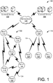
- FIG. 1 is a block diagram showing example smart grid network 100.
- the smart grid network includes two central offices 102, 104, each of which is in communication with a central network 106, such as the Internet.
- the central office 102 is in communication with a "mesh" type network 108, while the central office 104 is in communication with a "star" type network 110.
- the mesh network 108 includes nodes 112-122, which may be representative of a large number of nodes in a complex network.
- the network is a "mesh" network, in that each node may communicate with one or more adjacent nodes, such as by radio frequency (RF) communications 124 or over power line communications (PLC).
- RF radio frequency
- PLC power line communications
- one or more of nodes 112-122 may be an electric meter, which gathers consumption data using a metrology portion of the meter.
- a communications portion of the meter may send and/or relay the consumption data from a meter to an adjacent meter.
- Adjacent meters continue to relay the data until it reaches a root node (e.g., node 112) which may transfer the information through network 106 (e.g., using backhaul communications) to the central office 102.
- a root node e.g., node 112
- network 106 e.g., using backhaul communications
- one or more nodes 112-122 may have metrology hardware, e.g., devices that are configured to collect and manage consumption information (e.g., electrical usage or consumption) of a home, business or other establishment.
- each node 112-122 may have communications hardware, which may include RF radios and/or PLC devices to transmit information (e.g., within RF signal 124) to adjacent nodes.
- the metrology hardware, the communications hardware and/or other devices and functions may be controlled, managed and/or otherwise operated by a system on a module that is attached to, and part of, the node.
- the star network 110 includes nodes 126-132, which may be representative of a large number of nodes in a complex network.
- the network is a "star" network, in that each node 128-132 may communicate with a root node 126, such as by means of a cellular modem or other RF device.
- the root node 126 may be located "in the field" with the nodes 128-132, or may be located at the central office 104.
- one or more nodes 126-132 may have metrology hardware, e.g., devices that are configured to collect and manage consumption information (e.g., electrical usage or consumption) of a home, business or other establishment.
- each node 126-132 may have communications hardware, which may include a cellular modem and/or other RF radios or devices to transmit information 134 over backhaul communications to a root node or central office.
- the metrology hardware, the communications hardware and/or other devices and functions may be controlled, managed and/or otherwise operated by a system on a module that is attached to, and part of, the node.
- FIG. 2 is a block diagram showing example node 200, which may be operable within the smart grid network 100 of FIG. 1 .
- the example node 200 provides detail of hardware components consistent with a metering device to measure electrical consumption.
- the node could be another component in a smart grid (e.g., a relay) or a gas meter, water meter or other device.
- a system on a module 202 is connected (e.g., by an edge connector, surface mount solder connection or other means) to a mother board 204.
- the mother board 204 may include metrology hardware 206, which may measure the flow of electricity consumed by a customer, thereby creating "consumption data.”
- the motherboard 204 may communicate with a communications module 208, which may include one or more RF and/or PLC devices or modems 210.
- the RF or PLC devices 210 provide communication links to adjacent nodes and allow for formation and operation of a mesh network.
- the mother board 204 may communicate with the communications module 208, which may include a cellular modem 212 or other radio device having sufficiently long range communication ability to communicate with a root node or a central office.
- the communications module 208 will be provided with and/or utilize only one of the RF and/or PLC device 210 or cellular device 212.
- a meter base level PCB 214 may be instantiated on a separate printed wiring board (PWB) and/or printed circuit board (PCB).
- PWB printed wiring board
- PCB printed circuit board
- current to be measured may flow through the meter base level PCB 214.
- a connection between the meter base level PCB 214 and the motherboard 204 may include an elevated or extended half-turn coil.
- the half-turn coil may be located on the meter base level PCB 214, and may extend toward the metrology hardware 206 on the motherboard 204. In view of the extension, the half-turn coil may be physically located by or near elements of the metrology hardware 206.
- the half-turn coil may be located near a Hall effect sensor or other current measuring device on the metrology hardware 206.
- a shunt, a current transformer or a mutual induction coil can be used instead of the current coil and Hall effect sensor.
- the system on a module 202 manages the metrology hardware 206, meter base level PCB 214 and communications module 208 (and devices 210 and/or 212).
- the system on a module 202 may obtain and organize sensor data, consumption information and/or any auxiliary data (e.g., date and time) that is required. More particularly, current flow and/or power through the meter base level PCB 214 may be detected by sensor devices within the metrology hardware 206 of the motherboard 204.
- the system on a module 202 may organize and format the sensor data, timestamps, and other information.
- the system on a module 202 may perform current flow calculations, power consumption calculations, date and/or time recordings and/or information formatting.
- the system on a module 202 may manage data and information, and maintain data structures, data files and/or file systems.
- the system on a module 202 may also manage communications module 208, to control the RF and/or PLC hardware 210 and/or the cellular modem 212.
- the system on a module may control communications functionality, including creating packets, utilizing protocols and operating transmitting and/or receiving hardware. Accordingly, the system on a module 202 may transmit the sensor information, current or power consumption values and/or other desired information through the network (e.g., networks 108, 110 of FIG. 1 ).
- FIG. 3 is block diagram showing example detail of the system on a module 202 of FIG. 2 .
- the detail of FIG. 3 is intended to be representative, and not limiting; accordingly, some variation may be indicated by any particular implementation of a system on a module.
- an 80-pin edge connector facilitates connection to a motherboard or other connection site.
- a microprocessor may operate a memory management unit (MMU) and may execute an operating system (OS), such as LINUX or other modern OS.
- OS operating system
- the system on a module 202 may include flash memory device(s) and/or RAM memory device(s). These memory devices may be accessed by the processor, and used to store the operating system, drivers, utilities, program applications, data and/or data structures and other information.
- the system on a module 202 may include a metrology interface, which may be used to connect to metrology hardware (e.g., metrology hardware 206 in FIG. 2 ).
- the metrology interface may pass commands that control the external metrology hardware and that obtain consumption data.
- Such metrology hardware may be external, i.e., located off the system on a module 202.
- the metrology hardware is located on motherboard 204.
- the metrology interface may include several interface types, thereby allowing the system on a module 202 to be utilized with a variety of metrology devices.
- the metrology interface may include: a universal asynchronous receiver/transmitter (UART) (e.g., configured for a BLURT protocol); a watt disc emulator (WDE) configured for GPIO; a line sync (LSYNC) configured for GPIO; and/or other interfaces as indicated by needs.
- UART universal asynchronous receiver/transmitter
- WDE watt disc emulator
- LSYNC line sync
- the system on a module 202 may include a communications interface, which may be used to connect to communications hardware.
- Such communications hardware may be external, i.e., located off the system on a module 202.
- Communications module 208 of FIG. 2 is one example of such an external communications module.
- the communications interface may send commands and receive responses to control the external communications hardware. Additionally, the communications interface may pass information for transmission and/or upon receipt.
- the communications interface may include several interface types, thereby allowing the system on a module 202 to be utilized with a variety of communication devices and systems.
- the communications interface may include: universal serial bus (USB) ports, IDIO ports, inter-integrated circuit (I2C) interface ports, analog to digital converter (ADC) channel, secure digital input/output (SDIO) interface, serial port interface (SPI), universal asynchronous receiver/transmitter (UART) and/or general purpose input/output (GPIO).
- USB universal serial bus
- I2C inter-integrated circuit
- ADC analog to digital converter
- SDIO secure digital input/output
- SPI serial port interface
- UART universal asynchronous receiver/transmitter
- GPIO general purpose input/output
- a PIC microcontroller with real time clock may be used to provide time and date information, such as for use in conjunction with metrology data.
- An EPF, with power up/down logic may be used to reduce power consumption.
- a power management IC may be used to regulate voltages required by various devices on the system of a module 202. In the example shown, 3.3, 1.8 and 1.1 volt values are regulated. However, a different PMIC and/or different voltage values could be provided, as needed.
- FIG. 4 is a second example 400 of the system on a module of FIG. 2 .
- the system on a module 202 may be attached (e.g., by surface mount technology) to the mother board (e.g., motherboard 204 of FIG. 2 ).
- the mother board e.g., motherboard 204 of FIG. 2
- the system on a module may or may not be circuit-card mounted.
- the example of FIG. 4 is otherwise substantially similar the example of FIG. 3 .
- Several software elements are shown, including a metrology daemon, a LAN communications daemon, a home area network (HAN) daemon, a liquid crystal display (LCD) daemon and a gateway daemon.
- a Wi-Fi module which may be present in any version of the system on a module, is shown in the system on a module 400.
- FIG. 5 is block diagram showing an example of a file system 500, which may be defined in the flash memory (e.g., as seen in FIGS. 3 or 4 ) of the system on a module.
- the file system may include one or more presentation layers, such as presentation layers 502, 504.
- developers can use the base presentation layer classes to generate aspects including DLMS/COSEM, C12.22/C12.19 and SEP 2.0 support without changing any core functionality, such as the business layer 506.
- changes may be made to the upper layers 502, 504, without changing the lower layers 506-512. Accordingly, the system on a module may be developed more rapidly than if all software layers had to be redeveloped.
- network development may be facilitated by re-use of one or more software layers in two or more networks or on two or more nodes or node types.
- one or more presentation layers e.g., presentation layers 502, 504 may include software operable in a first network (e.g., mesh network 108 of FIG. 1 ).
- different presentation layers may be used in a second or different network (e.g., star network 110 of FIG. 1 ).
- Use of different presentation layers in different networks may be required due to differences in the networks' technologies (e.g., mesh network vs. star network) and/or different design constraints or requirements, etc.
- a business layer 506 and/or a data layer 510 may include software operable in both networks (e.g., networks 108 and 110).
- design of one network e.g., mesh network 108 may include one or more software layers (e.g., layers 506, 510) that may be re-used in a second network (e.g., star network 110).
- other software layers may have to be altered, re-written and/or recompiled.
- a whole disk encryption application 508 may be used to encrypt the entire file system 500 and/or the entire flash memory device on the system on a module seen in FIGS. 3 and/or 4.
- An encryption engine may utilize the application 508 and/or may utilize an algorithm based in hardware.
- the encryption engine may encrypt written to, and decrypt data read from, the file system on the flash memory.
- the encryption engine may incorporate a value (e.g., an integer or alpha-numeric character string) unique to the processor to perform the encryption and decryption. Because the unique value is not present in any other processor, movement of the flash memory to another system on a module will result in failure to decrypt the file system.
Landscapes
- Engineering & Computer Science (AREA)
- Theoretical Computer Science (AREA)
- Physics & Mathematics (AREA)
- General Physics & Mathematics (AREA)
- General Engineering & Computer Science (AREA)
- Computer Networks & Wireless Communication (AREA)
- Small-Scale Networks (AREA)
Abstract
Description
- This application claims priority to
U.S. Application No. 13/717,440, filed December 17, 2012 - Smart grid nodes within a utility communications network may include electrical consumption-measuring meters, gateways, relays and others. Such nodes require both hardware and software to gather, communicate and relay information. However, the operation and design requirements of different networks and nodes may be different. Traditionally, each different node required its own unique design, design test and design review. Accordingly, numerous different hardware devices have been designed to control the functionality of a broad range of smart grid nodes operable on a range of networks. The design, development and verification efforts for this broad range of control devices have been considerable.
- The detailed description is described with reference to the accompanying figures. In the figures, the left-most digit(s) of a reference number identifies the figure in which the reference number first appears. The same numbers are used throughout the drawings to reference like features and components. Moreover, the figures are intended to illustrate general concepts, and not to indicate required and/or necessary elements.
-
FIG. 1 is a block diagram showing example diverse network environments including diverse smart grid nodes, wherein any node may utilize a ubiquitous system on a module as a control device. -
FIG. 2 is a block diagram showing example detail of hardware components in a metering device that is representative of one or more nodes in the network(s) ofFIG. 1 . -
FIG. 3 is block diagram showing a first example of hardware aspects of the system on a module ofFIG. 2 . -
FIG. 4 is block diagram showing second example of hardware aspects of the system on a module ofFIG. 2 . -
FIG. 5 is block diagram showing example detail of software aspects of the system on a module ofFIG. 2 . - The disclosure describes techniques for providing a system on a module to control and/or operate a smart grid node, such as an electric meter, a data access (DA) gateway, a relay or other network component and/or node. In one example, the system on a module may include a processor, flash (persistent) memory, random access memory (RAM), and other components to provide interfaces. Examples of possible interfaces include a communications interface and/or a metrology interface.
- A communications interface may include one or more of universal serial bus (USB) ports, IDIO ports, inter-integrated circuit (I2C) interface ports, analog to digital converter (ADC) channel, secure digital input/output (SDIO) interface, serial port interface (SPI), universal asynchronous receiver/transmitter (UART) and/or general purpose input/output (GPIO). Use of any of these ports allows connection to external communications hardware, i.e. communications hardware that is not located on the system on a module. The communications hardware may be located on a communications module within the network node.
- The metrology interface may include one or more UART, Watt disk emulator (WDE) GPIO and/or line sync (LSYN) GPIO, etc. Use of any of these ports allows connection to external metrology hardware, i.e. metrology hardware (sensors, etc.) that is not located on the system on a module. The metrology hardware may be located on a motherboard within the network node.
- The discussion herein includes several sections. Each section is intended to be non-limiting. More generally, this entire description is intended to illustrate example aspects of example systems on a module, smart grid nodes and/or networks, but not components or techniques which are required. The discussion begins with a section entitled "Example Networks," which describes one environment that may implement the techniques described herein. This section depicts and describes smart grid networks and operation of a system on a module at a high-level architecture. Next, a section entitled "Example Smart Grid Device" illustrates and describes aspects of a system on a module, and how such a system may interface with, control and/or operate a smart grid node. This section addresses general concepts involving smart grid nodes with a specific example involving an electric meter. Next, a section entitled "Example System on a Module" illustrates and describes aspects that can be used to provide a system on a module for use in the utility industry, smart grids and electrical metering. This section addresses example aspects that may be used to provide a system on a module that is usable with a number of smart grid nodes, including electrical meters, DA gateways, relays, etc. Next, a section entitled "Example Software and File Systems" illustrates and describes aspects that can be used to provide software on an example system on a module adapted for use in the utility industry. This section addresses examples of software configuration that interact synergistically with the hardware of the system on a module. Finally, the discussion ends with a brief conclusion. This brief introduction is provided for the reader's convenience and is not intended to describe and/or limit the scope of the claims or any section of this disclosure.
-
FIG. 1 is a block diagram showing examplesmart grid network 100. In the example shown, the smart grid network includes twocentral offices central network 106, such as the Internet. In the example shown, thecentral office 102 is in communication with a "mesh"type network 108, while thecentral office 104 is in communication with a "star"type network 110. - The
mesh network 108 includes nodes 112-122, which may be representative of a large number of nodes in a complex network. The network is a "mesh" network, in that each node may communicate with one or more adjacent nodes, such as by radio frequency (RF)communications 124 or over power line communications (PLC). In one example, one or more of nodes 112-122 may be an electric meter, which gathers consumption data using a metrology portion of the meter. A communications portion of the meter may send and/or relay the consumption data from a meter to an adjacent meter. Adjacent meters continue to relay the data until it reaches a root node (e.g., node 112) which may transfer the information through network 106 (e.g., using backhaul communications) to thecentral office 102. - In one example, one or more nodes 112-122 may have metrology hardware, e.g., devices that are configured to collect and manage consumption information (e.g., electrical usage or consumption) of a home, business or other establishment. Similarly, each node 112-122 may have communications hardware, which may include RF radios and/or PLC devices to transmit information (e.g., within RF signal 124) to adjacent nodes. The metrology hardware, the communications hardware and/or other devices and functions may be controlled, managed and/or otherwise operated by a system on a module that is attached to, and part of, the node.
- The
star network 110 includes nodes 126-132, which may be representative of a large number of nodes in a complex network. The network is a "star" network, in that each node 128-132 may communicate with aroot node 126, such as by means of a cellular modem or other RF device. Theroot node 126 may be located "in the field" with the nodes 128-132, or may be located at thecentral office 104. - In one example, one or more nodes 126-132 may have metrology hardware, e.g., devices that are configured to collect and manage consumption information (e.g., electrical usage or consumption) of a home, business or other establishment. Similarly, each node 126-132 may have communications hardware, which may include a cellular modem and/or other RF radios or devices to transmit
information 134 over backhaul communications to a root node or central office. Moreover, the metrology hardware, the communications hardware and/or other devices and functions may be controlled, managed and/or otherwise operated by a system on a module that is attached to, and part of, the node. -
FIG. 2 is a block diagram showingexample node 200, which may be operable within thesmart grid network 100 ofFIG. 1 . Theexample node 200 provides detail of hardware components consistent with a metering device to measure electrical consumption. Alternatively, the node could be another component in a smart grid (e.g., a relay) or a gas meter, water meter or other device. In the example electric meter, a system on amodule 202 is connected (e.g., by an edge connector, surface mount solder connection or other means) to amother board 204. - The
mother board 204 may includemetrology hardware 206, which may measure the flow of electricity consumed by a customer, thereby creating "consumption data." In a manner consistent with the "mesh"network 108 ofFIG. 1 , themotherboard 204 may communicate with acommunications module 208, which may include one or more RF and/or PLC devices or modems 210. The RF orPLC devices 210 provide communication links to adjacent nodes and allow for formation and operation of a mesh network. - In a manner consistent with the "star"
network 110 ofFIG. 1 , themother board 204 may communicate with thecommunications module 208, which may include acellular modem 212 or other radio device having sufficiently long range communication ability to communicate with a root node or a central office. In many applications, thecommunications module 208 will be provided with and/or utilize only one of the RF and/orPLC device 210 orcellular device 212. - A meter
base level PCB 214 may be instantiated on a separate printed wiring board (PWB) and/or printed circuit board (PCB). In an electrical meter example, current to be measured may flow through the meterbase level PCB 214. A connection between the meterbase level PCB 214 and themotherboard 204 may include an elevated or extended half-turn coil. The half-turn coil may be located on the meterbase level PCB 214, and may extend toward themetrology hardware 206 on themotherboard 204. In view of the extension, the half-turn coil may be physically located by or near elements of themetrology hardware 206. For example, the half-turn coil may be located near a Hall effect sensor or other current measuring device on themetrology hardware 206. Alternatively, a shunt, a current transformer or a mutual induction coil can be used instead of the current coil and Hall effect sensor. - In operation, the system on a
module 202 manages themetrology hardware 206, meterbase level PCB 214 and communications module 208 (anddevices 210 and/or 212). The system on amodule 202 may obtain and organize sensor data, consumption information and/or any auxiliary data (e.g., date and time) that is required. More particularly, current flow and/or power through the meterbase level PCB 214 may be detected by sensor devices within themetrology hardware 206 of themotherboard 204. The system on amodule 202 may organize and format the sensor data, timestamps, and other information. The system on amodule 202 may perform current flow calculations, power consumption calculations, date and/or time recordings and/or information formatting. The system on amodule 202 may manage data and information, and maintain data structures, data files and/or file systems. - The system on a
module 202 may also managecommunications module 208, to control the RF and/orPLC hardware 210 and/or thecellular modem 212. The system on a module may control communications functionality, including creating packets, utilizing protocols and operating transmitting and/or receiving hardware. Accordingly, the system on amodule 202 may transmit the sensor information, current or power consumption values and/or other desired information through the network (e.g.,networks FIG. 1 ). -
FIG. 3 is block diagram showing example detail of the system on amodule 202 ofFIG. 2 . The detail ofFIG. 3 is intended to be representative, and not limiting; accordingly, some variation may be indicated by any particular implementation of a system on a module. - In the example system on a
module 202, an 80-pin edge connector facilitates connection to a motherboard or other connection site. A microprocessor may operate a memory management unit (MMU) and may execute an operating system (OS), such as LINUX or other modern OS. The system on amodule 202 may include flash memory device(s) and/or RAM memory device(s). These memory devices may be accessed by the processor, and used to store the operating system, drivers, utilities, program applications, data and/or data structures and other information. - The system on a
module 202 may include a metrology interface, which may be used to connect to metrology hardware (e.g.,metrology hardware 206 inFIG. 2 ). The metrology interface may pass commands that control the external metrology hardware and that obtain consumption data. Such metrology hardware may be external, i.e., located off the system on amodule 202. In the example ofFIG. 2 , the metrology hardware is located onmotherboard 204. The metrology interface may include several interface types, thereby allowing the system on amodule 202 to be utilized with a variety of metrology devices. The metrology interface may include: a universal asynchronous receiver/transmitter (UART) (e.g., configured for a BLURT protocol); a watt disc emulator (WDE) configured for GPIO; a line sync (LSYNC) configured for GPIO; and/or other interfaces as indicated by needs. - The system on a
module 202 may include a communications interface, which may be used to connect to communications hardware. Such communications hardware may be external, i.e., located off the system on amodule 202.Communications module 208 ofFIG. 2 is one example of such an external communications module. The communications interface may send commands and receive responses to control the external communications hardware. Additionally, the communications interface may pass information for transmission and/or upon receipt. The communications interface may include several interface types, thereby allowing the system on amodule 202 to be utilized with a variety of communication devices and systems. The communications interface may include: universal serial bus (USB) ports, IDIO ports, inter-integrated circuit (I2C) interface ports, analog to digital converter (ADC) channel, secure digital input/output (SDIO) interface, serial port interface (SPI), universal asynchronous receiver/transmitter (UART) and/or general purpose input/output (GPIO). - A PIC microcontroller with real time clock may be used to provide time and date information, such as for use in conjunction with metrology data. An EPF, with power up/down logic may be used to reduce power consumption. A power management IC may be used to regulate voltages required by various devices on the system of a
module 202. In the example shown, 3.3, 1.8 and 1.1 volt values are regulated. However, a different PMIC and/or different voltage values could be provided, as needed. -
FIG. 4 is a second example 400 of the system on a module ofFIG. 2 . In this example, the system on amodule 202 may be attached (e.g., by surface mount technology) to the mother board (e.g.,motherboard 204 ofFIG. 2 ). Thus the system on a module may or may not be circuit-card mounted. The example ofFIG. 4 is otherwise substantially similar the example ofFIG. 3 . Several software elements are shown, including a metrology daemon, a LAN communications daemon, a home area network (HAN) daemon, a liquid crystal display (LCD) daemon and a gateway daemon. A Wi-Fi module, which may be present in any version of the system on a module, is shown in the system on amodule 400. -
FIG. 5 is block diagram showing an example of afile system 500, which may be defined in the flash memory (e.g., as seen inFIGS. 3 or4 ) of the system on a module. The file system may include one or more presentation layers, such as presentation layers 502, 504. In one example, developers can use the base presentation layer classes to generate aspects including DLMS/COSEM, C12.22/C12.19 and SEP 2.0 support without changing any core functionality, such as the business layer 506. In a more general sense, changes may be made to theupper layers - In a further example, network development may be facilitated by re-use of one or more software layers in two or more networks or on two or more nodes or node types. In such an example, one or more presentation layers (e.g., presentation layers 502, 504) may include software operable in a first network (e.g.,
mesh network 108 ofFIG. 1 ). However, different presentation layers may be used in a second or different network (e.g.,star network 110 ofFIG. 1 ). Use of different presentation layers in different networks may be required due to differences in the networks' technologies (e.g., mesh network vs. star network) and/or different design constraints or requirements, etc. However, even if some software layers designed for a first network have to be changed for use in a second network, other software layers may be re-used. For example, a business layer 506 and/or a data layer 510 (including data structures 512) may include software operable in both networks (e.g.,networks 108 and 110). Accordingly, design of one network (e.g., mesh network 108) may include one or more software layers (e.g., layers 506, 510) that may be re-used in a second network (e.g., star network 110). However, other software layers may have to be altered, re-written and/or recompiled. - In one example, a whole
disk encryption application 508 may be used to encrypt theentire file system 500 and/or the entire flash memory device on the system on a module seen inFIGS. 3 and/or 4. An encryption engine may utilize theapplication 508 and/or may utilize an algorithm based in hardware. In operation, the encryption engine may encrypt written to, and decrypt data read from, the file system on the flash memory. The encryption engine may incorporate a value (e.g., an integer or alpha-numeric character string) unique to the processor to perform the encryption and decryption. Because the unique value is not present in any other processor, movement of the flash memory to another system on a module will result in failure to decrypt the file system. - Although the subject matter has been described in language specific to structural features and/or methodological acts, it is to be understood that the subject matter defined in the appended claims is not necessarily limited to the specific features or acts described. Rather, the specific features and acts are disclosed as exemplary forms of implementing the claims.
- The disclosure comprises the subject matter described in the following clauses:
- Clause 1. A system on a module, comprising:
- a processor;
- a flash memory device, in communication with the processor;
- a random access memory (RAM) device, in communication with the processor; and
- a connector to provide an interface to a smart grid device, the interface comprising two types of metrology interfaces.
- Clause 2. The system on a module of clause 1, wherein the interface to a smart grid device of the system on a module is configured for use with:
- a gateway;
- an electrical meter; and
- a relay.
- Clause 3. A smart grid, comprising a plurality of smart grid components, including at least one each of:
- a gateway comprising the system on a module of clause 1 and having at least two software layers; and
- an electric meter comprising the system on a module of clause 1 and having at least two software layers, wherein:
- one software layer is the same as a software layer of the system on a module of the gateway; and
- one software layer is different from all software layers of the system on a module of the gateway.
- Clause 4. A smart grid node, comprising:
- the system on a module of clause 1, additionally comprising at least three types of communications interfaces; and
- a communication module communicatively coupled to the system on a module;
- wherein the system on a module directs, using commands sent through one of the at least three types of communications interfaces, the communication module to transmit data in a network.
- Clause 5. An electric meter, comprising:
- the system on a module of clause 1, wherein metrology and communications functions of the electric meter are controlled by the system on a module;
- a motherboard controlled by the system on a module, comprising metrology hardware;
- a communications module to connect to a network and to communicate metrology information obtained from the metrology hardware; and
- a meter base level printed circuit board (PCB) in communication with the mother board, the meter base level PCB comprising:
- a current-carrying elements on the PCB; and
- switches to regulate the current on the PCB.
- Clause 6. The system on a module of clause 1, wherein the at least two types of metrology interfaces are selected from among a group consisting of:
- a universal asynchronous receiver/transmitter (UART) configured for a one-way messaging (BLURT) protocol;
- a watt disc emulator (WDE) configured for general purpose input/output (GPIO); and
- a line sync (LSYNC) configured for GPIO.
- Clause 7. The system on a module of clause 1, additionally comprising at least three types of communications interfaces, selected from among a group consisting of:
- a universal serial bus (USB);
- a secure digital input/output (SDIO) interface;
- an inter-integrated circuit (I2C) interface;
- an analog to digital converter (ADC) channel;
- a serial port interface (SPI);
- a universal asynchronous receiver/transmitter (UART); and
- a general purpose input/output (GPIO).
- Clause 8. The system on a module of clause 1, wherein layers of software in the flash memory comprise:
- a presentation layer to include software operable in a first network;
- a business layer to include software operable in the first network and a second network; and
- a data layer to include software and data structures operable in the first network and the second network;
- wherein content in the layers are separately compiled and stored with a file system defined on the flash memory.
- Clause 9. The system on a module of clause 1, additionally comprising:
an encryption engine to encrypt and decrypt data in a file system on the flash memory based at least in part on a value unique to the processor. - Clause 10. A system on a module, comprising:
- a processor;
- a flash memory device, in communication with the processor;
- a random access memory (RAM) memory device, in communication with the processor; and
- a connector to provide an interface to components on an electric meter and to pass instructions from the processor to the components on the electric meter to control:
- metrology hardware within the electric meter to measure consumption data; and
- communications module hardware within the electric meter to transmit the consumption data.
- Clause 11. An electric meter, comprising:
- the system on a module of clause 10;
- the metrology hardware, in communication with the processor; and
- the communication module hardware, in communication with the processor;
- wherein the system on a module of directs the communication module to transmit and/or receive data via a network.
- Clause 12. A smart grid component, comprising:
- the system on a module of clause 10; and
- the communication module hardware, in communication with the processor;
- wherein the system on a module directs operation of the communication module.
- Clause 13. The system on a module of clause 10, additionally comprising:
- a universal asynchronous receiver/transmitter (UART) in communication with the processor;
- a watt disc emulator (WDE) in communication with the processor; and
- a line sync (LSYNC) in communication with the processor.
- Clause 14. The system on a module of clause 10, wherein the system on a module has hardware interfaces for backhaul communications on star and mesh networks and for backhaul communications over a direct cellular connection, radio frequency (RF) and power line communications (PLC).
- Clause 15. The system on a module of clause 10, wherein:
- the system on a module has hardware interfaces to communications devices operable on star and mesh networks; and
- the processor is configured to provide instructions over at least one of the hardware interfaces to the communications devices.
- Clause 16. The system on a module of clause 10, additionally comprising an encryption engine to encrypt and decrypt data in a file system on the flash memory based on an internal value unique to the processor.
- Clause 17. A system on a module, comprising:
- a processor;
- a flash memory device, in communication with the processor;
- a RAM memory device, in communication with the processor;
- a metrology interface to control metrology hardware and to obtain consumption data, the metrology hardware external to the system on a module; and
- a communications interface to control communications hardware and to transmit and receive data, the communications hardware external to the system on a module;
- wherein the processor is configured to format the consumption data and to direct the communications hardware to transmit the formatted consumption data.
- Clause 18. A star network, comprising:
a plurality of network devices, each comprising the system on a module of clause 17, wherein the system on a module controls direct cellular connection communications hardware. - Clause 19. A mesh network, comprising:
a plurality of network devices, each comprising the system on a module of clause 17, wherein the system on a module controls radio frequency (RF) communications hardware to communicate with at least one adjacent node. - Clause 20. A smart grid component, comprising:
- the system on a module of clause 17;
- the communications hardware, in communication with the processor;
- wherein the system on a module directs operation of the communication hardware.
Claims (15)
- A system on a module, comprising:a processor;a memory in communication with the processor;a connector to provide an interface to a smart grid device, the interface comprising two types of metrology interfaces.
- The system on a module of claim 1, wherein the connector is configured to:
provide an interface to components on a utility meter and to pass instructions from the processor to the components on the utility meter to control:metrology hardware within the utility meter to measure consumption data; andcommunications module hardware within the utility meter to transmit the consumption data. - A utility meter, comprising:the system on a module of claim 2;the metrology hardware, in communication with the processor; and the communication module hardware, in communication with the processor;wherein the system on a module of directs the communication module to transmit and/or receive data via a network.
- A smart grid component, comprising:the system on a module of claim 2; andthe communication module hardware, in communication with the processor;wherein the system on a module directs operation of the communication module.
- The system on a module of claim 2, additionally comprising:a universal asynchronous receiver/transmitter (UART) in communication with the processor;a watt disc emulator (WDE) in communication with the processor; anda line sync (LSYNC) in communication with the processor.
- The system on a module of claim 2, wherein the system on a module has hardware interfaces for backhaul communications on star and mesh networks and for backhaul communications over a direct cellular connection, radio frequency (RF) and power line communications (PLC).
- The system on a module of claim 2, wherein:the system on a module has hardware interfaces to communications devices operable on star and mesh networks; andthe processor is configured to provide instructions over at least one of the hardware interfaces to the communications devices; orthe system on the module additionally comprising an encryption engine to encrypt and decrypt data in a file system on the memory based on an internal value unique to the processor.
- The system on a module of any preceding claim, wherein the interface to a smart grid device of the system on a module is configured for use with:a gateway;a utility meter; anda relay.
- A smart grid, comprising a plurality of smart grid components, including at least one each of:a gateway comprising the system on a module of claim of any preceding claim and having at least two software layers; anda utility meter comprising the system on a module of any preceding claim and having at least two software layers, wherein:one software layer is the same as a software layer of the system on a module of the gateway; andone software layer is different from all software layers of the system on a module of the gateway.
- A smart grid node, comprising:the system on a module of any preceding claim, additionally comprising at least three types of communications interfaces; anda communication module communicatively coupled to the system on a module;wherein the system on a module directs, using commands sent through one of the at least three types of communications interfaces, the communication module to transmit data in a network.
- A utility meter, comprising:the system on a module of any preceding claim 1 , wherein metrology and communications functions of the utility meter are controlled by the system on a module;a motherboard controlled by the system on a module, comprising metrology hardware;a communications module to connect to a network and to communicate metrology information obtained from the metrology hardware; anda meter base level printed circuit board (PCB) in communication with the mother board, the meter base level PCB comprising:a current-carrying elements on the PCB; andswitches to regulate the current on the PCB.
- The system on a module of any preceding claim, wherein the at least two types of metrology interfaces are selected from among a group consisting of:a universal asynchronous receiver/transmitter (UART) configured for a one-way messaging (BLURT) protocol;a watt disc emulator (WDE) configured for general purpose input/output (GPIO); anda line sync (LSYNC) configured for GPIO.
- The system on a module of any preceding claim, additionally comprising at least three types of communications interfaces, selected from among a group consisting of:a universal serial bus (USB);a secure digital input/output (SDIO) interface;an inter- integrated circuit (I C) interface;an analog to digital converter (ADC) channel;a serial port interface (SPI);a universal asynchronous receiver/transmitter (UART); anda general purpose input/output (GPIO).
- The system on a module of any preceding claim, wherein layers of software in the memory comprise:a presentation layer to include software operable in a first network; a business layer to include software operable in the first network and a second network; anda data layer to include software and data structures operable in the first network and the second network;wherein content in the layers are separately compiled and stored with a file system defined on the memory.
- The system on a module of any preceding claim, additionally comprising:
an encryption engine to encrypt and decrypt data in a file system on the memory based at least in part on a value unique to the processor.
Applications Claiming Priority (3)
| Application Number | Priority Date | Filing Date | Title |
|---|---|---|---|
| US13/717,440 US9280505B2 (en) | 2012-12-17 | 2012-12-17 | System on a module for smart grid nodes |
| EP13786770.1A EP2932727B1 (en) | 2012-12-17 | 2013-09-30 | System on a module for smart grid nodes |
| PCT/US2013/062752 WO2014099093A1 (en) | 2012-12-17 | 2013-09-30 | System on a module for smart grid nodes |
Related Parent Applications (1)
| Application Number | Title | Priority Date | Filing Date |
|---|---|---|---|
| EP13786770.1A Division EP2932727B1 (en) | 2012-12-17 | 2013-09-30 | System on a module for smart grid nodes |
Publications (2)
| Publication Number | Publication Date |
|---|---|
| EP3651474A1 true EP3651474A1 (en) | 2020-05-13 |
| EP3651474B1 EP3651474B1 (en) | 2022-02-16 |
Family
ID=49551731
Family Applications (2)
| Application Number | Title | Priority Date | Filing Date |
|---|---|---|---|
| EP13786770.1A Active EP2932727B1 (en) | 2012-12-17 | 2013-09-30 | System on a module for smart grid nodes |
| EP19196523.5A Active EP3651474B1 (en) | 2012-12-17 | 2013-09-30 | System on a module for smart grid nodes |
Family Applications Before (1)
| Application Number | Title | Priority Date | Filing Date |
|---|---|---|---|
| EP13786770.1A Active EP2932727B1 (en) | 2012-12-17 | 2013-09-30 | System on a module for smart grid nodes |
Country Status (3)
| Country | Link |
|---|---|
| US (1) | US9280505B2 (en) |
| EP (2) | EP2932727B1 (en) |
| WO (1) | WO2014099093A1 (en) |
Cited By (1)
| Publication number | Priority date | Publication date | Assignee | Title |
|---|---|---|---|---|
| JP2023013807A (en) * | 2021-07-16 | 2023-01-26 | 大成建設株式会社 | Wireless measuring module and state quantity measuring system |
Families Citing this family (11)
| Publication number | Priority date | Publication date | Assignee | Title |
|---|---|---|---|---|
| US11172273B2 (en) | 2015-08-10 | 2021-11-09 | Delta Energy & Communications, Inc. | Transformer monitor, communications and data collection device |
| WO2017027682A1 (en) | 2015-08-11 | 2017-02-16 | Delta Energy & Communications, Inc. | Enhanced reality system for visualizing, evaluating, diagnosing, optimizing and servicing smart grids and incorporated components |
| US10055966B2 (en) | 2015-09-03 | 2018-08-21 | Delta Energy & Communications, Inc. | System and method for determination and remediation of energy diversion in a smart grid network |
| CA3000206C (en) | 2015-10-02 | 2023-10-17 | Delta Energy & Communications, Inc. | Supplemental and alternative digital data delivery and receipt mesh network realized through the placement of enhanced transformer mounted monitoring devices |
| WO2017070646A1 (en) | 2015-10-22 | 2017-04-27 | Delta Energy & Communications, Inc. | Data transfer facilitation across a distributed mesh network using light and optical based technology |
| US9961572B2 (en) | 2015-10-22 | 2018-05-01 | Delta Energy & Communications, Inc. | Augmentation, expansion and self-healing of a geographically distributed mesh network using unmanned aerial vehicle (UAV) technology |
| EP3185021A1 (en) | 2015-12-23 | 2017-06-28 | Phoenix Systems Sp. z o.o. | Multiphase electricity meter based on a configurable processor and a real-time system, hereinafter referred to as digital electricity measurement system, for use in smart grid power networks |
| CA3054546C (en) | 2016-02-24 | 2022-10-11 | Delta Energy & Communications, Inc. | Distributed 802.11s mesh network using transformer module hardware for the capture and transmission of data |
| US10652633B2 (en) | 2016-08-15 | 2020-05-12 | Delta Energy & Communications, Inc. | Integrated solutions of Internet of Things and smart grid network pertaining to communication, data and asset serialization, and data modeling algorithms |
| CN113238081A (en) * | 2021-05-24 | 2021-08-10 | 苏州大学 | Intelligent electric meter terminal |
| IT202300020694A1 (en) * | 2023-10-05 | 2025-04-05 | Salvatore Cerrito | COMBINED SYSTEM(S) ON PRINTED CIRCUIT FOR READING, DECODING, STORAGE AND TRANSMISSION OF DATA FROM THE ELECTRICITY NETWORK TO A CENTRAL SERVER |
Citations (1)
| Publication number | Priority date | Publication date | Assignee | Title |
|---|---|---|---|---|
| US20120054540A1 (en) * | 2010-08-25 | 2012-03-01 | Smartsynch, Inc. | System and method for automated unattended recovery for remotely deployed intelligent communication devices |
Family Cites Families (10)
| Publication number | Priority date | Publication date | Assignee | Title |
|---|---|---|---|---|
| US8411590B2 (en) * | 2006-07-27 | 2013-04-02 | Mobitrum Corporation | Mesh network remote control device |
| WO2009046132A1 (en) | 2007-10-01 | 2009-04-09 | Gridpoint, Inc. | Modular electrical grid interface device |
| US8423637B2 (en) * | 2010-08-06 | 2013-04-16 | Silver Spring Networks, Inc. | System, method and program for detecting anomalous events in a utility network |
| US8738195B2 (en) * | 2010-09-21 | 2014-05-27 | Intel Corporation | Inferencing energy usage from voltage droop |
| US8606423B2 (en) | 2011-01-18 | 2013-12-10 | General Electric Company | HEG—single primary network to multiple secondary network energy management |
| BRPI1100227A8 (en) | 2011-02-18 | 2015-10-27 | João Machado Magalhães De Almeida | modular measurement and control collection management system for energy, water and gas |
| US20120274440A1 (en) * | 2011-04-29 | 2012-11-01 | General Electric Company | Method and system to disconnect a utility service based on seismic activity |
| US8581743B2 (en) * | 2011-09-21 | 2013-11-12 | Jetlun Corporation | Method and system for automated power meter infrastructure |
| US10134266B2 (en) * | 2012-09-05 | 2018-11-20 | Itron Networked Solutions, Inc. | Dual mode smart grid meter |
| US9201104B2 (en) * | 2012-10-08 | 2015-12-01 | Tyco Electronics Corporation | Intelligent power sensing device |
-
2012
- 2012-12-17 US US13/717,440 patent/US9280505B2/en active Active
-
2013
- 2013-09-30 WO PCT/US2013/062752 patent/WO2014099093A1/en not_active Ceased
- 2013-09-30 EP EP13786770.1A patent/EP2932727B1/en active Active
- 2013-09-30 EP EP19196523.5A patent/EP3651474B1/en active Active
Patent Citations (1)
| Publication number | Priority date | Publication date | Assignee | Title |
|---|---|---|---|---|
| US20120054540A1 (en) * | 2010-08-25 | 2012-03-01 | Smartsynch, Inc. | System and method for automated unattended recovery for remotely deployed intelligent communication devices |
Cited By (2)
| Publication number | Priority date | Publication date | Assignee | Title |
|---|---|---|---|---|
| JP2023013807A (en) * | 2021-07-16 | 2023-01-26 | 大成建設株式会社 | Wireless measuring module and state quantity measuring system |
| JP7742603B2 (en) | 2021-07-16 | 2025-09-22 | 大成建設株式会社 | State quantity measurement system |
Also Published As
| Publication number | Publication date |
|---|---|
| US20140167977A1 (en) | 2014-06-19 |
| EP2932727A1 (en) | 2015-10-21 |
| EP3651474B1 (en) | 2022-02-16 |
| EP2932727B1 (en) | 2019-09-11 |
| US9280505B2 (en) | 2016-03-08 |
| WO2014099093A1 (en) | 2014-06-26 |
Similar Documents
| Publication | Publication Date | Title |
|---|---|---|
| US9280505B2 (en) | System on a module for smart grid nodes | |
| US9885739B2 (en) | Intelligent electronic device capable of operating as a USB master device and a USB slave device | |
| US10474591B2 (en) | Electronic meter with a removable protective plug | |
| Salvadori et al. | Monitoring in industrial systems using wireless sensor network with dynamic power management | |
| JP7110340B2 (en) | Wireless and high-performance weighing device | |
| CN109300298A (en) | A power data information acquisition system with Internet of things function | |
| CN110618397B (en) | Module power-on detection device based on ubiquitous power Internet of Things smart energy meter | |
| US20130211754A1 (en) | Extensible Power Meter | |
| Minchev et al. | Home automation system based on ESP8266 | |
| US9348618B2 (en) | Systems and methods for enhancing firmware | |
| CN103455678B (en) | Quadratic Imaginary loop chart collaborative design method based on the empty terminal of standardization | |
| CN103152274A (en) | Energy efficiency and safety data wireless network routing device, energy efficiency and safety data wireless network routing system and method applying same | |
| JP2012234548A (en) | Calculation of auxiliary value based on meter data from non-smart electronic utility meter | |
| Jaganmohan et al. | Challenges in smart meter design | |
| Jaybhaye et al. | IoT based Smart Power Grid Monitoring and Control using Arduino | |
| RuiChoo et al. | 4 Design and implementation of IoT-enabled smart single-phase energy meter monitoring system | |
| CN120128822A (en) | Wellsite data wireless explosion-proof display terminal data transmission device, method and system | |
| CN119814870A (en) | Data transmission method, device and electronic equipment | |
| Zinner | Remote Power Meter | |
| CN114095315A (en) | Instrument and meter system architecture | |
| Casey et al. | Senior Design Project: Smart Consumer Home Network Appliance Power System | |
| HK40036980A (en) | Radio and advanced metering device | |
| HK40036980B (en) | Radio and advanced metering device | |
| Aamir et al. | Hardware Implementation and Testing of Reconfigurable RTU for Wireless SCADA | |
| Lluna et al. | Sensor Network to Measure Electric Parameters |
Legal Events
| Date | Code | Title | Description |
|---|---|---|---|
| PUAI | Public reference made under article 153(3) epc to a published international application that has entered the european phase |
Free format text: ORIGINAL CODE: 0009012 |
|
| STAA | Information on the status of an ep patent application or granted ep patent |
Free format text: STATUS: THE APPLICATION HAS BEEN PUBLISHED |
|
| AC | Divisional application: reference to earlier application |
Ref document number: 2932727 Country of ref document: EP Kind code of ref document: P |
|
| AK | Designated contracting states |
Kind code of ref document: A1 Designated state(s): AL AT BE BG CH CY CZ DE DK EE ES FI FR GB GR HR HU IE IS IT LI LT LU LV MC MK MT NL NO PL PT RO RS SE SI SK SM TR |
|
| STAA | Information on the status of an ep patent application or granted ep patent |
Free format text: STATUS: REQUEST FOR EXAMINATION WAS MADE |
|
| 17P | Request for examination filed |
Effective date: 20201113 |
|
| RBV | Designated contracting states (corrected) |
Designated state(s): AL AT BE BG CH CY CZ DE DK EE ES FI FR GB GR HR HU IE IS IT LI LT LU LV MC MK MT NL NO PL PT RO RS SE SI SK SM TR |
|
| GRAP | Despatch of communication of intention to grant a patent |
Free format text: ORIGINAL CODE: EPIDOSNIGR1 |
|
| STAA | Information on the status of an ep patent application or granted ep patent |
Free format text: STATUS: GRANT OF PATENT IS INTENDED |
|
| INTG | Intention to grant announced |
Effective date: 20210330 |
|
| GRAJ | Information related to disapproval of communication of intention to grant by the applicant or resumption of examination proceedings by the epo deleted |
Free format text: ORIGINAL CODE: EPIDOSDIGR1 |
|
| STAA | Information on the status of an ep patent application or granted ep patent |
Free format text: STATUS: REQUEST FOR EXAMINATION WAS MADE |
|
| GRAP | Despatch of communication of intention to grant a patent |
Free format text: ORIGINAL CODE: EPIDOSNIGR1 |
|
| STAA | Information on the status of an ep patent application or granted ep patent |
Free format text: STATUS: GRANT OF PATENT IS INTENDED |
|
| INTC | Intention to grant announced (deleted) | ||
| INTG | Intention to grant announced |
Effective date: 20210909 |
|
| GRAS | Grant fee paid |
Free format text: ORIGINAL CODE: EPIDOSNIGR3 |
|
| GRAA | (expected) grant |
Free format text: ORIGINAL CODE: 0009210 |
|
| STAA | Information on the status of an ep patent application or granted ep patent |
Free format text: STATUS: THE PATENT HAS BEEN GRANTED |
|
| AC | Divisional application: reference to earlier application |
Ref document number: 2932727 Country of ref document: EP Kind code of ref document: P |
|
| AK | Designated contracting states |
Kind code of ref document: B1 Designated state(s): AL AT BE BG CH CY CZ DE DK EE ES FI FR GB GR HR HU IE IS IT LI LT LU LV MC MK MT NL NO PL PT RO RS SE SI SK SM TR |
|
| REG | Reference to a national code |
Ref country code: GB Ref legal event code: FG4D |
|
| REG | Reference to a national code |
Ref country code: CH Ref legal event code: EP |
|
| REG | Reference to a national code |
Ref country code: DE Ref legal event code: R096 Ref document number: 602013080942 Country of ref document: DE |
|
| REG | Reference to a national code |
Ref country code: AT Ref legal event code: REF Ref document number: 1469646 Country of ref document: AT Kind code of ref document: T Effective date: 20220315 |
|
| REG | Reference to a national code |
Ref country code: IE Ref legal event code: FG4D |
|
| REG | Reference to a national code |
Ref country code: SE Ref legal event code: TRGR |
|
| REG | Reference to a national code |
Ref country code: LT Ref legal event code: MG9D |
|
| REG | Reference to a national code |
Ref country code: NL Ref legal event code: MP Effective date: 20220216 |
|
| REG | Reference to a national code |
Ref country code: AT Ref legal event code: MK05 Ref document number: 1469646 Country of ref document: AT Kind code of ref document: T Effective date: 20220216 |
|
| PG25 | Lapsed in a contracting state [announced via postgrant information from national office to epo] |
Ref country code: RS Free format text: LAPSE BECAUSE OF FAILURE TO SUBMIT A TRANSLATION OF THE DESCRIPTION OR TO PAY THE FEE WITHIN THE PRESCRIBED TIME-LIMIT Effective date: 20220216 Ref country code: PT Free format text: LAPSE BECAUSE OF FAILURE TO SUBMIT A TRANSLATION OF THE DESCRIPTION OR TO PAY THE FEE WITHIN THE PRESCRIBED TIME-LIMIT Effective date: 20220616 Ref country code: NO Free format text: LAPSE BECAUSE OF FAILURE TO SUBMIT A TRANSLATION OF THE DESCRIPTION OR TO PAY THE FEE WITHIN THE PRESCRIBED TIME-LIMIT Effective date: 20220516 Ref country code: NL Free format text: LAPSE BECAUSE OF FAILURE TO SUBMIT A TRANSLATION OF THE DESCRIPTION OR TO PAY THE FEE WITHIN THE PRESCRIBED TIME-LIMIT Effective date: 20220216 Ref country code: LT Free format text: LAPSE BECAUSE OF FAILURE TO SUBMIT A TRANSLATION OF THE DESCRIPTION OR TO PAY THE FEE WITHIN THE PRESCRIBED TIME-LIMIT Effective date: 20220216 Ref country code: HR Free format text: LAPSE BECAUSE OF FAILURE TO SUBMIT A TRANSLATION OF THE DESCRIPTION OR TO PAY THE FEE WITHIN THE PRESCRIBED TIME-LIMIT Effective date: 20220216 Ref country code: ES Free format text: LAPSE BECAUSE OF FAILURE TO SUBMIT A TRANSLATION OF THE DESCRIPTION OR TO PAY THE FEE WITHIN THE PRESCRIBED TIME-LIMIT Effective date: 20220216 Ref country code: BG Free format text: LAPSE BECAUSE OF FAILURE TO SUBMIT A TRANSLATION OF THE DESCRIPTION OR TO PAY THE FEE WITHIN THE PRESCRIBED TIME-LIMIT Effective date: 20220516 |
|
| PG25 | Lapsed in a contracting state [announced via postgrant information from national office to epo] |
Ref country code: PL Free format text: LAPSE BECAUSE OF FAILURE TO SUBMIT A TRANSLATION OF THE DESCRIPTION OR TO PAY THE FEE WITHIN THE PRESCRIBED TIME-LIMIT Effective date: 20220216 Ref country code: LV Free format text: LAPSE BECAUSE OF FAILURE TO SUBMIT A TRANSLATION OF THE DESCRIPTION OR TO PAY THE FEE WITHIN THE PRESCRIBED TIME-LIMIT Effective date: 20220216 Ref country code: GR Free format text: LAPSE BECAUSE OF FAILURE TO SUBMIT A TRANSLATION OF THE DESCRIPTION OR TO PAY THE FEE WITHIN THE PRESCRIBED TIME-LIMIT Effective date: 20220517 Ref country code: FI Free format text: LAPSE BECAUSE OF FAILURE TO SUBMIT A TRANSLATION OF THE DESCRIPTION OR TO PAY THE FEE WITHIN THE PRESCRIBED TIME-LIMIT Effective date: 20220216 Ref country code: AT Free format text: LAPSE BECAUSE OF FAILURE TO SUBMIT A TRANSLATION OF THE DESCRIPTION OR TO PAY THE FEE WITHIN THE PRESCRIBED TIME-LIMIT Effective date: 20220216 |
|
| PG25 | Lapsed in a contracting state [announced via postgrant information from national office to epo] |
Ref country code: IS Free format text: LAPSE BECAUSE OF FAILURE TO SUBMIT A TRANSLATION OF THE DESCRIPTION OR TO PAY THE FEE WITHIN THE PRESCRIBED TIME-LIMIT Effective date: 20220617 |
|
| PG25 | Lapsed in a contracting state [announced via postgrant information from national office to epo] |
Ref country code: SM Free format text: LAPSE BECAUSE OF FAILURE TO SUBMIT A TRANSLATION OF THE DESCRIPTION OR TO PAY THE FEE WITHIN THE PRESCRIBED TIME-LIMIT Effective date: 20220216 Ref country code: SK Free format text: LAPSE BECAUSE OF FAILURE TO SUBMIT A TRANSLATION OF THE DESCRIPTION OR TO PAY THE FEE WITHIN THE PRESCRIBED TIME-LIMIT Effective date: 20220216 Ref country code: RO Free format text: LAPSE BECAUSE OF FAILURE TO SUBMIT A TRANSLATION OF THE DESCRIPTION OR TO PAY THE FEE WITHIN THE PRESCRIBED TIME-LIMIT Effective date: 20220216 Ref country code: EE Free format text: LAPSE BECAUSE OF FAILURE TO SUBMIT A TRANSLATION OF THE DESCRIPTION OR TO PAY THE FEE WITHIN THE PRESCRIBED TIME-LIMIT Effective date: 20220216 Ref country code: DK Free format text: LAPSE BECAUSE OF FAILURE TO SUBMIT A TRANSLATION OF THE DESCRIPTION OR TO PAY THE FEE WITHIN THE PRESCRIBED TIME-LIMIT Effective date: 20220216 Ref country code: CZ Free format text: LAPSE BECAUSE OF FAILURE TO SUBMIT A TRANSLATION OF THE DESCRIPTION OR TO PAY THE FEE WITHIN THE PRESCRIBED TIME-LIMIT Effective date: 20220216 |
|
| REG | Reference to a national code |
Ref country code: DE Ref legal event code: R097 Ref document number: 602013080942 Country of ref document: DE |
|
| PG25 | Lapsed in a contracting state [announced via postgrant information from national office to epo] |
Ref country code: AL Free format text: LAPSE BECAUSE OF FAILURE TO SUBMIT A TRANSLATION OF THE DESCRIPTION OR TO PAY THE FEE WITHIN THE PRESCRIBED TIME-LIMIT Effective date: 20220216 |
|
| PLBE | No opposition filed within time limit |
Free format text: ORIGINAL CODE: 0009261 |
|
| STAA | Information on the status of an ep patent application or granted ep patent |
Free format text: STATUS: NO OPPOSITION FILED WITHIN TIME LIMIT |
|
| 26N | No opposition filed |
Effective date: 20221117 |
|
| PG25 | Lapsed in a contracting state [announced via postgrant information from national office to epo] |
Ref country code: SI Free format text: LAPSE BECAUSE OF FAILURE TO SUBMIT A TRANSLATION OF THE DESCRIPTION OR TO PAY THE FEE WITHIN THE PRESCRIBED TIME-LIMIT Effective date: 20220216 |
|
| REG | Reference to a national code |
Ref country code: DE Ref legal event code: R119 Ref document number: 602013080942 Country of ref document: DE |
|
| PG25 | Lapsed in a contracting state [announced via postgrant information from national office to epo] |
Ref country code: MC Free format text: LAPSE BECAUSE OF FAILURE TO SUBMIT A TRANSLATION OF THE DESCRIPTION OR TO PAY THE FEE WITHIN THE PRESCRIBED TIME-LIMIT Effective date: 20220216 |
|
| REG | Reference to a national code |
Ref country code: CH Ref legal event code: PL |
|
| P01 | Opt-out of the competence of the unified patent court (upc) registered |
Effective date: 20230519 |
|
| PG25 | Lapsed in a contracting state [announced via postgrant information from national office to epo] |
Ref country code: LU Free format text: LAPSE BECAUSE OF NON-PAYMENT OF DUE FEES Effective date: 20220930 |
|
| PG25 | Lapsed in a contracting state [announced via postgrant information from national office to epo] |
Ref country code: LI Free format text: LAPSE BECAUSE OF NON-PAYMENT OF DUE FEES Effective date: 20220930 Ref country code: IT Free format text: LAPSE BECAUSE OF FAILURE TO SUBMIT A TRANSLATION OF THE DESCRIPTION OR TO PAY THE FEE WITHIN THE PRESCRIBED TIME-LIMIT Effective date: 20220216 Ref country code: IE Free format text: LAPSE BECAUSE OF NON-PAYMENT OF DUE FEES Effective date: 20220930 Ref country code: DE Free format text: LAPSE BECAUSE OF NON-PAYMENT OF DUE FEES Effective date: 20230401 Ref country code: CH Free format text: LAPSE BECAUSE OF NON-PAYMENT OF DUE FEES Effective date: 20220930 |
|
| PG25 | Lapsed in a contracting state [announced via postgrant information from national office to epo] |
Ref country code: CY Free format text: LAPSE BECAUSE OF FAILURE TO SUBMIT A TRANSLATION OF THE DESCRIPTION OR TO PAY THE FEE WITHIN THE PRESCRIBED TIME-LIMIT Effective date: 20220216 |
|
| PG25 | Lapsed in a contracting state [announced via postgrant information from national office to epo] |
Ref country code: MK Free format text: LAPSE BECAUSE OF FAILURE TO SUBMIT A TRANSLATION OF THE DESCRIPTION OR TO PAY THE FEE WITHIN THE PRESCRIBED TIME-LIMIT Effective date: 20220216 Ref country code: HU Free format text: LAPSE BECAUSE OF FAILURE TO SUBMIT A TRANSLATION OF THE DESCRIPTION OR TO PAY THE FEE WITHIN THE PRESCRIBED TIME-LIMIT; INVALID AB INITIO Effective date: 20130930 |
|
| PG25 | Lapsed in a contracting state [announced via postgrant information from national office to epo] |
Ref country code: TR Free format text: LAPSE BECAUSE OF FAILURE TO SUBMIT A TRANSLATION OF THE DESCRIPTION OR TO PAY THE FEE WITHIN THE PRESCRIBED TIME-LIMIT Effective date: 20220216 |
|
| PG25 | Lapsed in a contracting state [announced via postgrant information from national office to epo] |
Ref country code: MT Free format text: LAPSE BECAUSE OF FAILURE TO SUBMIT A TRANSLATION OF THE DESCRIPTION OR TO PAY THE FEE WITHIN THE PRESCRIBED TIME-LIMIT Effective date: 20220216 |
|
| PGFP | Annual fee paid to national office [announced via postgrant information from national office to epo] |
Ref country code: BE Payment date: 20250818 Year of fee payment: 13 Ref country code: GB Payment date: 20250807 Year of fee payment: 13 |
|
| PGFP | Annual fee paid to national office [announced via postgrant information from national office to epo] |
Ref country code: FR Payment date: 20250808 Year of fee payment: 13 |
|
| PGFP | Annual fee paid to national office [announced via postgrant information from national office to epo] |
Ref country code: SE Payment date: 20250812 Year of fee payment: 13 |