EP3651369B1 - Dispositif électronique et procédé de réception d'un signal radioélectrique, circuit intégré implémentant un tel dispositif - Google Patents
Dispositif électronique et procédé de réception d'un signal radioélectrique, circuit intégré implémentant un tel dispositif Download PDFInfo
- Publication number
- EP3651369B1 EP3651369B1 EP19207043.1A EP19207043A EP3651369B1 EP 3651369 B1 EP3651369 B1 EP 3651369B1 EP 19207043 A EP19207043 A EP 19207043A EP 3651369 B1 EP3651369 B1 EP 3651369B1
- Authority
- EP
- European Patent Office
- Prior art keywords
- gain
- signal
- increase
- power
- amplifier
- Prior art date
- Legal status (The legal status is an assumption and is not a legal conclusion. Google has not performed a legal analysis and makes no representation as to the accuracy of the status listed.)
- Active
Links
Images

Classifications
-
- H—ELECTRICITY
- H03—ELECTRONIC CIRCUITRY
- H03G—CONTROL OF AMPLIFICATION
- H03G3/00—Gain control in amplifiers or frequency changers
- H03G3/20—Automatic control
- H03G3/30—Automatic control in amplifiers having semiconductor devices
- H03G3/3052—Automatic control in amplifiers having semiconductor devices in bandpass amplifiers (H.F. or I.F.) or in frequency-changers used in a (super)heterodyne receiver
- H03G3/3078—Circuits generating control signals for digitally modulated signals
-
- H—ELECTRICITY
- H04—ELECTRIC COMMUNICATION TECHNIQUE
- H04B—TRANSMISSION
- H04B1/00—Details of transmission systems, not covered by a single one of groups H04B3/00 - H04B13/00; Details of transmission systems not characterised by the medium used for transmission
- H04B1/06—Receivers
-
- H—ELECTRICITY
- H04—ELECTRIC COMMUNICATION TECHNIQUE
- H04B—TRANSMISSION
- H04B1/00—Details of transmission systems, not covered by a single one of groups H04B3/00 - H04B13/00; Details of transmission systems not characterised by the medium used for transmission
- H04B1/06—Receivers
- H04B1/16—Circuits
-
- H—ELECTRICITY
- H03—ELECTRONIC CIRCUITRY
- H03F—AMPLIFIERS
- H03F1/00—Details of amplifiers with only discharge tubes, only semiconductor devices or only unspecified devices as amplifying elements
- H03F1/32—Modifications of amplifiers to reduce non-linear distortion
-
- H—ELECTRICITY
- H03—ELECTRONIC CIRCUITRY
- H03F—AMPLIFIERS
- H03F3/00—Amplifiers with only discharge tubes or only semiconductor devices as amplifying elements
- H03F3/189—High-frequency amplifiers, e.g. radio frequency amplifiers
- H03F3/19—High-frequency amplifiers, e.g. radio frequency amplifiers with semiconductor devices only
-
- H—ELECTRICITY
- H03—ELECTRONIC CIRCUITRY
- H03G—CONTROL OF AMPLIFICATION
- H03G3/00—Gain control in amplifiers or frequency changers
- H03G3/20—Automatic control
- H03G3/30—Automatic control in amplifiers having semiconductor devices
- H03G3/3052—Automatic control in amplifiers having semiconductor devices in bandpass amplifiers (H.F. or I.F.) or in frequency-changers used in a (super)heterodyne receiver
-
- H—ELECTRICITY
- H04—ELECTRIC COMMUNICATION TECHNIQUE
- H04B—TRANSMISSION
- H04B17/00—Monitoring; Testing
- H04B17/20—Monitoring; Testing of receivers
-
- H—ELECTRICITY
- H03—ELECTRONIC CIRCUITRY
- H03F—AMPLIFIERS
- H03F2200/00—Indexing scheme relating to amplifiers
- H03F2200/451—Indexing scheme relating to amplifiers the amplifier being a radio frequency amplifier
Definitions
- the present invention relates to an electronic device for receiving a radioelectric signal, the device comprising an upstream amplifier configured to amplify a radioelectric signal received, a piloting module configured to pilot a gain of the upstream amplifier and a mixer, connected at the output of the upstream amplifier, the mixer being configured to mix the signal coming from the upstream amplifier with a reference signal.
- the invention also relates to an integrated circuit implementing such an electronic device for receiving a radioelectric signal.
- the invention also relates to a method for receiving a radioelectric signal, the method being implemented by such an electronic reception device.
- the invention relates to the field of tuners , that is to say electronic devices making it possible to receive an electromagnetic signal emitted on a frequency band, to keep the part of the signal emitted on a particular frequency , also called useful frequency, and to reject the parts of the signal emitted on the other frequencies.
- the invention relates more particularly to analog tuners, whatever the range of radio waves concerned.
- the invention relates for example to radio tuners, such as FM ( Frequency Modulation ), AM ( Amplitude Modulation ), DAB ( Digital Audio Broadcasting ) or HD Radio tuners.
- the invention also relates to TV tuners, such as DVB-T ( Digital Video Broadcasting - Terrestrial ), DVB-T 2, ISDB-T/Tsb ( Integrated Services Digital Broadcasting - Terrestrial / Terrestrial Sound Broadcast ) or CTTB (from the English China Terrestrial Television Broadcasting ) .
- DVB-T Digital Video Broadcasting - Terrestrial
- DVB-T 2 Digital Video Broadcasting - Terrestrial
- ISDB-T/Tsb Integrated Services Digital Broadcasting - Terrestrial / Terrestrial Sound Broadcast
- CTTB from the English China Terrestrial Television Broadcasting
- the reception device comprises an upstream amplifier amplifying a radioelectric signal received via an antenna, a WBAGC ( Wide Band Automatic Gain Control ) module for controlling the gain of the upstream amplifier, and a mixer connected to the output of the upstream amplifier and mixing the signal from the upstream amplifier with another signal.
- This reception device further comprises a downstream amplifier connected to the output of the mixer and an intermodulation detector able to detect intermodulation from the signal delivered by the downstream amplifier, and to generating, if necessary, an intermodulation indicator, intended for the control module WBAGC, so that the latter then adapts the gain of the upstream amplifier as a function of any detected intermodulation.
- the receiving device is an FM radio signal receiving device, and the intermodulation detector detects intermodulation from large frequency variations beyond standard FM deviations and associated noise resulting from broad frequency spectra .
- the document US 2008/0102773 A1 also relates to an electronic reception device of the aforementioned type. It comprises an upstream amplifier amplifying a radioelectric signal received from an antenna, a gain controller controlling the gain of the upstream amplifier, a mixer connected to the output of the upstream amplifier and mixing the signal from the upstream amplifier with a another signal, a downstream amplifier connected to the output of the mixer and an analog-to-digital converter connected to the output of the downstream amplifier.
- the reception device further comprises a detector of intermodulation products from the signal coming from the analog-digital converter, the gain controller then being adapted to modify the gain of the upstream amplifier as a function of the detection or not of such intermodulation products.
- the intermodulation products are for example detected via a rate of variation of the noise increase in one or more channels adjacent to the channel carrying the radioelectric signal, or even by directly detecting these intermodulation products on a guard band comprising a part of the channel carrying the radio signal.
- the document US 2008/0153447 A1 also describes an electronic reception device of the aforementioned type.
- This reception device comprises a variable gain amplifier amplifying a received radioelectric signal, an amplifier gain controller and a mixer connected to the output of the amplifier and mixing the signal coming from the amplifier with another signal.
- the reception device further comprises a downstream detector connected at the output of the mixer and an upstream detector connected at the input of the mixer, the upstream and downstream detectors being capable of detecting interference, and in particular an intermodulation phenomenon, the downstream detector connected detecting if an interfering signal is present on a frequency adjacent to 6 MHz from the useful frequency, corresponding to an offset N+1, and the upstream detector detecting if an interfering signal is present on an adjacent frequency beyond 6 MHz from the frequency useful, typically at 18 MHz from the frequency of the useful signal corresponding to an offset N+3.
- the controller then adapts the gain of the amplifier according to the detection or not of an intermodulation.
- the object of the invention is therefore to propose an electronic device for receiving a radioelectric signal making it possible to detect intermodulation more easily.
- the subject of the invention is an electronic device for receiving a radioelectric signal, according to claim 1.
- control module then makes it possible to simply perform intermodulation detection, by controlling the generation of a gain increase at the level of the upstream amplifier and by comparing the first power measured in the absence of gain increase with the second power measured in the presence of the gain increase, the first and second powers being powers of the signal coming from the mixer.
- an intermodulation is detected when a power increase, controlled by the control module and generated with the aim of carrying out this intermodulation detection, generates an abnormal variation of the power of the signal at the output of the mixer, in particular a non-linear variation of this power.
- the electronic reception device is according to any one of claims 2 to 9.
- the invention also relates to an integrated circuit according to claim 10.
- the invention also relates to a method for receiving a radioelectric signal, according to claim 11.
- the expression “substantially equal to” is understood as a relation of equality of plus or minus 10%, that is to say with a variation of at most 10%; more preferably as a relation of equality at plus or minus 5%, that is to say with a variation of at most 5%.
- an electronic reception device 10 is configured to receive a radioelectric signal.
- the electronic reception device 10 is typically a tuner , that is to say a device making it possible to receive an electromagnetic signal emitted on a frequency band, to keep the part of the signal emitted on a frequency particular, called useful frequency, and to reject the parts of the signal transmitted on frequencies other than the useful frequency.
- the electronic reception device 10 is for example an analog tuner configured to tune signals transmitted analogically, regardless of the associated radio wave range.
- the tuner is for example a radio tuner, such as an FM tuner capable of receiving a radio signal transmitted in the frequency range between 87.5 MHz and 108 MHz; or an AM tuner capable of receiving a radioelectric signal comprised in the frequency range comprised between 148.5 kHz and 283.5 kHz and/or between 526.5 kHz and 1606.5 kHz; or a DAB tuner; or an HD Radio tuner.
- the tuner is a TV tuner, such as a DVB-T tuner; or a DVB-T 2 tuner; or an ISDB-T tuner; or even a CTTB tuner.
- the TV tuner is for example able to receive a radioelectric signal transmitted in the frequency range between 40 MHz and 860 MHz.
- the electronic reception device 10 comprises a radioelectric antenna 12 capable of receiving a radioelectric signal, an upstream amplifier 14 connected to the radioelectric antenna 12 and configured to amplify the radioelectric signal received by the antenna 12, the upstream amplifier 14 being preferably a variable gain amplifier, also called VGA ( Variable Gain Amplifier ) and as symbolized by the arrow associated with the triangular amplification symbol on the figure 1 .
- VGA Variable Gain Amplifier
- the electronic reception device 10 comprises a control module 16 configured to control a gain G of the upstream amplifier 14 and a mixer 18 connected to the output of the upstream amplifier 14, the mixer 18 being configured to mix the signal from the upstream amplifier 14 with a reference signal, such as a signal from an oscillator 20 to which the mixer 18 is then connected.
- a control module 16 configured to control a gain G of the upstream amplifier 14 and a mixer 18 connected to the output of the upstream amplifier 14, the mixer 18 being configured to mix the signal from the upstream amplifier 14 with a reference signal, such as a signal from an oscillator 20 to which the mixer 18 is then connected.
- the electronic reception device 10 comprises a downstream amplifier 22 connected to the output of the mixer 18 and an analog-digital converter 24, also called ADC ( Analog to Digital Converter ), the analog-digital converter 24 being connected to the output of the downstream amplifier 22.
- ADC Analog to Digital Converter
- the electronic reception device 10 comprises a first broadband detector 26, also called WBD ( Wide Band Détecter ), connected between the output of the upstream amplifier 14 and the driver module 16, the first broadband detector 26 being capable of measuring a power of the radioelectric signal between the upstream amplifier 14 and the mixer 18, also called the useful signal.
- WBD Wide Band Détecter
- the electronic reception device 10 comprises a second broadband detector 28 connected between the radio antenna 12 and the control module 16, the second broadband detector 28 being capable of measuring the power of the signal received by antenna 12.
- the electronic reception device 10 is for example produced in the form of one or more dedicated integrated circuits, such as one or more ASICs ( Application Specifies Integrated Circuit ) .
- ASICs Application Specifies Integrated Circuit
- the radioelectric antenna 12 is known per se, and has a shape adapted to the range of radioelectric waves able to be received by the electronic reception device 10, whether it is the radio range (AM, FM, DAB , HD Radio, ISDB-Tsb) or a TV range (DVB-T, DVB-T 2, ISDB-T, CTTB), described previously.
- the upstream amplifier 14 is also known per se, and has a gain G, the value of which can be controlled by the control module 16.
- control module 16 is further configured to perform intermodulation detection, by controlling the generation by the upstream amplifier 14 of a gain increase ⁇ G and by comparing a first power P1 with a second power P2.
- the first P1 and second P2 powers are respective powers of the signal at the output of the mixer 18, that is to say of the signal coming from the mixer 18, the first power P1 being measured in the absence of increase in gain of the upstream amplifier 14, and the second power P2 being measured in the presence of the increase in gain ⁇ G.
- first power P1 in the absence of gain increase is meant the power of the signal from the mixer 18, for example measured via the analog-digital converter 24, corresponding to the default gain of the upstream amplifier 14, without the increase of gain ⁇ G, for example at a nominal gain, denoted G nom .
- the first power P1 is then also denoted P(G nom ), or even P ADC (G nom ) when measured through the analog-to-digital converter 24, also called ADC.
- second power P2 in the presence of the increase in gain ⁇ G is meant the power of the signal coming from the mixer 18, for example measured via the analog-digital converter 24, corresponding to the same default gain of the upstream amplifier 14 with in addition the increase in gain ⁇ G, that is to say corresponds to the sum of said default gain and the increase in gain ⁇ G.
- the second power P2 is then also denoted P(G nom + ⁇ G), or even P ADC (G nom + ⁇ G) when it is measured via the converter analog-digital 24, also known as ADC.
- the first and second powers P1, P2 are for example measured by the analog-digital converter 24, and the control module 16 is then connected to said analog-digital converter 24.
- the control module 16 is for example configured to detect an intermodulation, that is to say to consider that an intermodulation is present, if a difference between the second power P2 and the first power P1 is greater than substantially 1.5 times the gain increase ⁇ G.
- an intermodulation is detected if the difference between the second power P2 and the first power P1 is substantially greater than ⁇ G+2dB.
- the increase in gain ⁇ G is preferably of short duration in order to disturb as little as possible the signal delivered at the output of the reception device 10.
- the increase in gain ⁇ G is for example a gain pulse having a short duration, such as a duration of less than 100 ⁇ s, preferably substantially equal to 50 ⁇ s.
- the increase in gain ⁇ G is preferably greater than the default value of the gain G.
- the increase in gain ⁇ G depends on an amplitude of the radioelectric signal received and on a maximum amplitude of the signal before saturation of the electronic reception device 10, in particular before saturation of the analog-digital converter 24.
- the amplitude of the increase in gain ⁇ G is for example equal to the difference between said maximum amplitude before saturation and the amplitude of the radioelectric signal received.
- the control module 16 is configured to repeatedly control the generation of the gain increase ⁇ G.
- repetitively is meant a reiteration at successive time intervals, the repetitive generation of the increase in gain ⁇ G preferably being substantially periodic, with for example a periodicity substantially equal to 1 ms, as long as no modulation has been detected and as long as the gain of the upstream amplifier 14 is less than the predefined maximum upstream gain G max .
- control module 16 is configured to increase the time difference between a new increase in gain ⁇ G n+1 generated at a time instant t n+1 and a last increase in gain ⁇ G n generated at a time instant t n in the event of detection of an intermodulation following the last increase in gain ⁇ G n .
- control module 16 in the event of detection of an intermodulation, is then configured to temporally space the next increase in gain ⁇ G n+1 with respect to the last increase in gain ⁇ G n having caused the detection of this intermodulation. This makes it possible to limit any oscillations of the useful signal, and to prevent the detection of intermodulation from causing a disturbance of the signal delivered at the output of the reception device 10.
- the time difference between two successive increases in gain ⁇ G n , ⁇ G n+1 is for example substantially equal to 1 ms if no intermodulation has been detected following the last increase in gain ⁇ G n and if the gain G of the upstream amplifier 14 is less than a predefined maximum upstream gain G max .
- the time difference between the time instant t n of generation of the last increase in gain ⁇ G n and the time instant t n+1 of generation of the next increase in gain ⁇ G n+1 is for example substantially equal to 20 ms.
- the gain G of the upstream amplifier 14 is substantially equal to the predefined maximum upstream gain G max , then the time difference between two successive time instants t n , t n+1 of successive increases in gain ⁇ G n , ⁇ G n+1 is greater than that following an intermodulation detection, and is for example substantially equal to 50 ms.
- the driver module 16 is configured to increase over a short period, and preferably repeatedly, the gain of the upstream amplification and to then measure the increase in power on the signal coming from of the mixer 18. If the increase in power is of the same order as the variation in the amplification, that is to say if the variation in the power of the signal coming from the mixer as a function of the variation in the gain is substantially linear , then the control module 16 considers that the reception device 10 is not in an intermodulation situation. On the contrary, if the increase in power is much greater than the gain variation of the upstream amplification, the control module 16 considers that an intermodulation is present.
- the control module 16 is further configured to apply or not instructions from the first broadband detector 26, and optionally in addition to the second broadband detector 28, depending on whether or not an intermodulation has been detected. More precisely, if the piloting module 16 considers that no intermodulation is present, then it is configured to ignore the instructions coming from the broadband detector(s) 26, 28. Otherwise, if the piloting module 16 considers that an intermodulation is present, it is then configured to apply each gain modification setpoint from the broadband detector(s) 26, 28.
- control module 16 is also configured to, prior to the intermodulation detection, carry out a test for the presence of at least one parasitic adjacent signal, for example of at least one strong adjacent signal.
- the control module 16 is then configured to carry out the intermodulation detection only if the presence test is positive, that is to say if at least one parasitic adjacent signal is considered to be present, said presence test depending on the power of the signal at the output of the mixer 18 and of the gain G of the upstream amplifier 14.
- the presence test is for example positive if the gain G of the upstream amplifier is lower than the predefined maximum upstream gain G max , preferably much lower than said predefined maximum upstream gain G max , and if the power of the signal at the output of the mixer 18 , for example measured by the analog-digital converter 24, is strictly less than a predefined target power P c .
- the presence test is negative if the aforementioned conditions are not met.
- gain much lower than said predefined maximum upstream gain G max is meant for example a lower gain of at least 2dB compared to said predefined maximum upstream gain Gmax .
- power lower than the predefined target power P c is meant for example a power of 2 dB below said target power P c .
- the determination of the predefined target power P c is known per se, and the predefined target power P c is for example determined as a function of the waveform to be demodulated and also of a PAPR (from English Peak to Average Power Ratio ) of the waveform to have the maximum dynamics at the level of the analog-digital converter 24 without causing saturation.
- a PAPR from English Peak to Average Power Ratio
- the reception device further comprises the downstream amplifier 22 connected to the output of the mixer 18, the test for the presence of at least one parasitic adjacent signal also depends on a gain ⁇ of the downstream amplifier 22.
- the presence test is for example positive if the power of the signal at the output of the mixer 18 is lower than the predefined target power P c and if the gain G of the upstream amplifier 14 is lower than the predefined maximum upstream gain G max and furthermore if the gain ⁇ of the downstream amplifier 22 is substantially equal to a predefined maximum downstream gain ⁇ max .
- the choice of the predefined maximum upstream gain G max , and if necessary of the predefined maximum downstream gain ⁇ max , are known per se.
- Each predefined maximum gain G max , ⁇ max is dependent on the amplifier concerned, and is qualified on the reception device 10 in which the invention is implemented.
- the predefined maximum upstream gain G max is substantially equal to 40dB
- the predefined maximum downstream gain ⁇ max is substantially equal to 25dB.
- the mixer 18 is known per se and is configured to mix the signal coming from the upstream amplifier 14 - called the useful signal - with the reference signal, for example by multiplying these two signals, the voltage of the signal at the output of the mixer then being the product of the useful signal voltage and the reference signal voltage.
- the reference signal is typically an unmodulated signal, for example a signal from local oscillator 20, and mixer 18 is then connected to local oscillator 20.
- the local oscillator 20 is capable of supplying the reference signal, such as the unmodulated signal, this unmodulated signal allowing, via the mixer 18, the transposition of the useful signal to an intermediate frequency.
- the downstream amplifier 22 is known per se, and is suitable for amplifying the signal coming from the mixer 18.
- the analog-digital converter 24 is connected at the output of the downstream amplifier 22 when it is present, or else directly at the output of the mixer 18 in the absence downstream amplifier, and is configured to convert the analog signal from the mixer 18, possibly amplified by the downstream amplifier 22, into a digital signal.
- the analog-digital converter 24 is also configured to measure the power of the signal coming from the mixer 18, in particular the first power P1 in the absence of gain increase, then the second power P2 in the presence of the gain increase. gain ⁇ G.
- Each broadband detector 26, 28 is known per se, and is able to regulate the amplification performed by the upstream amplifier 14 by measuring the power of the signal coming from the upstream amplifier 14 for the first broadband detector 26, or even by measuring the power of the signal coming from the radioelectric antenna 12 for the second broadband detector 28 when it is present, and by generating a gain setpoint in order to regulate the power if the power measured is outside a predefined power range.
- each broadband detector 26, 28 aims to prevent excessive amplification of the radioelectric signal by the upstream amplifier 14, and more generally to limit the introduction by the upstream amplifier 14 of a non-linearity on the signal received.
- the reception device 10 performs, via its control module 16, a test for the presence of at least one parasitic adjacent signal based on the power of the signal at the output of the mixer 18 and the gain G of the upstream amplifier 14, or even from the gain ⁇ of the downstream amplifier 22.
- the presence test is for example positive if the gain G of the upstream amplifier 14 is much lower than the predefined maximum upstream gain G max and if the power of the signal at the output of the mixer 18 is strictly lower than the predefined target power P c , the presence test being negative otherwise.
- the presence test is positive if the gain G of the upstream amplifier 14 is less than the predefined maximum upstream gain G max , and if the gain ⁇ of the downstream amplifier 22 is substantially equal to the predefined maximum downstream gain ⁇ max , and furthermore if the power P of the signal at the output of the mixer 18 is lower than the predefined target power P c , the presence test being negative otherwise.
- the reception device 10 moves on to the next step 110 during which it performs, via its control module 16, a detection of a possible intermodulation.
- This intermodulation detection comprises the generation by the upstream amplifier 14 of the increase in gain ⁇ G, then the comparison of the first and second powers P1, P2 of the signal coming from the mixer 18, the first power P1 being measured in the absence of gain increase and the second power P2 being measured in the presence of the gain increase ⁇ G .
- the control module 16 then considers that an intermodulation is present when the variation of the power P of the signal at the output of the mixer 18, corresponding to the difference between the second power P2 and the first power P1, is non-linear with respect to the gain increase ⁇ G, typically if the difference between the second power P2 and the first power P1 is greater than substantially 1.5 times the gain increase ⁇ G.
- the control module 16 considers that an intermodulation 16 is present. Otherwise, i.e. if the power variation P2-P1 is substantially linear with respect to the increase in gain ⁇ G, for example if the inequalities (1) or (2) are not verified, then the modulus of control 16 considers that no intermodulation is detected.
- step 110 If the intermodulation detection carried out during step 110 is positive, that is to say if the control module 16 considers that an intermodulation is present, then the reception device 10 passes to step 120 at the during which the control module 16 controls the gain G of the upstream amplifier 14 by taking into account any setpoints for modifying the gain G from the broadband detector(s) 26, 28.
- the reception device 10 passes to the step 130 during which the control module 16 controls the gain G of the upstream amplifier 14 while ignoring any instructions from the broadband detector(s) 26, 28.
- step 100 of testing for the presence of at least one parasitic adjacent signal the test is negative, that is to say if no parasitic adjacent signal is detected, then the reception device 10 goes directly from step 100 to step 120 of controlling the gain to take into account any setpoints for modifying the gain G from the broadband detector(s) 26, 28.
- reception device 10 does not perform the optional initial step 100, then it starts the reception method directly at step 110.
- the reception device 10 At the end of step 120 of controlling the gain with consideration of WBD set point(s) or else at the end of step 130 of controlling the gain without taking into account setpoint(s) WBD, the reception device 10 then amplifies, during step 140, the radioelectric signal received via its upstream amplifier 14.
- the reception device 10 then mixes, during step 150, the signal coming from the upstream amplifier 14, called the useful signal, with the reference signal, preferably unmodulated, via its mixer 18, and the analog signal from the mixer 18 is then converted into the digital signal by the analog-digital converter 24.
- This digital signal converted by the analog-digital converter 24 corresponds to the signal provided at the output of the reception device 10.
- the signal thus converted by the analog-digital converter 24 is then typically digitally filtered, if necessary resampled (adaptation of the frequency of sampling in the case of digital signals), and demodulated by a receiver placed at the output of the reception device.
- the demodulated signal then becomes an audio and/or video signal intended to be reproduced by a third-party device (car radio, TV, etc.).
- the reception method then returns to step 100 or to step 110 depending on whether the optional initial step 100 is carried out or not, in order to carry out the reception of a new radioelectric signal.
- the electronic reception device 10 makes it possible to carry out, more simply and via the control module 16, a detection of a possible intermodulation, by controlling the generation by the upstream amplifier 14 of the increase in gain ⁇ G, then by observing whether the variation in power of the signal coming from the mixer 18, resulting from this increase in gain ⁇ G, is a substantially linear variation, or on the contrary a non-linear variation, with respect to the increase in gain ⁇ G generated.
- An intermodulation is then considered to be present, if the power variation P2-P1 of the signal at the output of the mixer 18 is non-linear with respect to the increase in gain ⁇ G.
- no intermodulation is considered to be present, if the power variation P2-P1 is substantially linear with respect to the gain increase ⁇ G generated.
- the generation by the upstream amplifier 14 of the increase in gain ⁇ G is preferably controlled repeatedly by the control module 16 in order to perform this intermodulation detection at successive time intervals.
- the time difference between two successive instants t n , t n+1 of generation of two successive increases in gain ⁇ G n , ⁇ G n+1 also preferably depends on whether or not an intermodulation has been detected following the last increase in gain ⁇ G n and the value of the gain G of the upstream amplifier 14 with respect to the predefined maximum upstream gain G max , which makes it possible to limit the risk of introducing possible oscillations due to this intermodulation detection, and which would then potentially disturb the signal delivered at the output of the reception device 10.
- the generation of the gain increase ⁇ G is then for example controlled periodically with a relatively low temporal periodicity, typically with a time period substantially equal to 1 ms, only if no intermodulation has been detected following the last gain increase ⁇ G n and if the gain G of the upstream amplifier 14 is less than the predefined maximum upstream gain G max . Otherwise, if the gain G of the upstream amplifier 14 is substantially equal to the predefined maximum upstream gain G max , then the time difference between a next increase in gain ⁇ G n+1 and the previous increase in gain ⁇ G n is significantly increased, typically substantially equal to 50 ms.
- the time difference between the next increase in gain ⁇ G n+1 and the last increase in gain ⁇ G n is also increased, this increase being however less, the time difference then being typically substantially equal to 20 ms, than in the case where the gain G of the upstream amplifier 14 is substantially equal to the predefined maximum upstream gain G max .
- the electronic reception device 10 makes it possible to perform the detection of any intermodulation in a simpler manner than with an electronic reception device of the state of the art.
Landscapes
- Engineering & Computer Science (AREA)
- Computer Networks & Wireless Communication (AREA)
- Signal Processing (AREA)
- Physics & Mathematics (AREA)
- Power Engineering (AREA)
- Nonlinear Science (AREA)
- Electromagnetism (AREA)
- Circuits Of Receivers In General (AREA)
- Noise Elimination (AREA)
- Control Of Amplification And Gain Control (AREA)
Description
- La présente invention concerne un dispositif électronique de réception d'un signal radioélectrique, le dispositif comprenant un amplificateur amont configuré pour amplifier un signal radioélectrique reçu, un module de pilotage configuré pour piloter un gain de l'amplificateur amont et un mélangeur, connecté en sortie de l'amplificateur amont, le mélangeur étant configuré pour mélanger le signal issu de l'amplificateur amont avec un signal de référence.
- L'invention concerne également un circuit intégré implémentant un tel dispositif électronique de réception d'un signal radioélectrique.
- L'invention concerne aussi un procédé de réception d'un signal radioélectrique, le procédé étant mis en oeuvre par un tel dispositif électronique de réception.
- L'invention concerne le domaine des syntoniseurs (de l'anglais tuner), c'est-à-dire des appareils électroniques permettant de recevoir un signal électromagnétique émis sur une bande de fréquences, de conserver la partie du signal émise sur une fréquence particulière, également appelée fréquence utile, et de rejeter les parties du signal émises sur les autres fréquences. L'invention concerne plus particulièrement les syntoniseurs analogiques, quelle que soit la gamme d'ondes radioélectriques concernée. L'invention concerne par exemple les syntoniseurs radio, tel que les syntoniseurs FM (de l'anglais Frequency Modulation), AM (de l'anglais Amplitude Modulation), DAB (de l'anglais Digital Audio Broadcasting), ou encore HD Radio. L'invention concerne aussi les syntoniseurs TV, tels que les syntoniseurs DVB-T (de l'anglais Digital Video Broadcasting - Terrestrial), DVB-T 2, ISDB-T/Tsb (de l'anglais Integrated Services Digital Broadcasting - Terrestrial/ Terrestrial Sound Broadcast) ou encore CTTB (de l'anglais China Terrestrial Télévision Broadcasting).
- On connaît du document
US 2004/0043733 A1 un dispositif électronique de réception du type précité. Le dispositif de réception comprend un amplificateur amont amplifiant un signal radioélectrique reçu via une antenne, un module WBAGC (de l'anglais Wide Band Automatic Gain Control) de pilotage du gain de l'amplificateur amont, et un mélangeur connecté en sortie de l'amplificateur amont et mélangeant le signal issu de l'amplificateur amont avec un autre signal. Ce dispositif de réception comprend en outre un amplificateur aval connecté en sortie du mélangeur et un détecteur d'intermodulation apte à détecter une intermodulation à partir du signal délivré par l'amplificateur aval, et à générer, le cas échéant, un indicateur d'intermodulation, à destination du module de pilotage WBAGC, afin que ce dernier adapte ensuite le gain de l'amplificateur amont en fonction d'une éventuelle intermodulation détectée. Le dispositif de réception est un dispositif de réception de signaux radio FM, et le détecteur d'intermodulation détecte une intermodulation à partir de variations de fréquences importantes au-delà d'écarts FM standards et d'un bruit associé résultant de larges spectres de fréquences. - Le document
US 2008/0102773 A1 concerne aussi un dispositif électronique de réception du type précité. Il comprend un amplificateur amont amplifiant un signal radioélectrique reçu d'une antenne, un contrôleur de gain pilotant le gain de l'amplificateur amont, un mélangeur connecté en sortie de l'amplificateur amont et mélangeant le signal issu de l'amplificateur amont avec un autre signal, un amplificateur aval connecté en sortie du mélangeur et un convertisseur analogique numérique connecté en sortie de l'amplificateur aval. Le dispositif de réception comprend en outre un détecteur de produits d'intermodulation à partir du signal issu du convertisseur analogique-numérique, le contrôleur de gain étant alors adapté pour modifier le gain de l'amplificateur amont en fonction de la détection ou non de tels produits d'intermodulation. Les produits d'intermodulation sont par exemple détectés via un taux de variation de l'augmentation du bruit dans un ou plusieurs canaux adjacents au canal acheminant le signal radioélectrique, ou encore en détectant directement ces produits d'intermodulation sur une bande de garde comprenant une partie du canal transportant le signal radioélectrique. - Le document
US 2008/0153447 A1 décrit également un dispositif électronique de réception du type précité. Ce dispositif de réception comprend un amplificateur de gain variable amplifiant un signal radioélectrique reçu, un contrôleur du gain de l'amplificateur et un mélangeur connecté en sortie de l'amplificateur et mélangeant le signal issu de l'amplificateur avec un autre signal. Le dispositif de réception comprend en outre un détecteur aval connecté en sortie du mélangeur et un détecteur amont connecté en entrée du mélangeur, les détecteurs amont et aval étant aptes à détecter des interférences, et notamment un phénomène d'intermodulation, le détecteur aval connecté détectant si un signal interférant est présent sur une fréquence adjacente à 6 MHz de la fréquence utile, correspondant à un décalage N+1, et le détecteur amont détectant si un signal interférant est présent sur une fréquence adjacente au-delà de 6 MHz de la fréquence utile, typiquement à 18 MHz de la fréquence du signal utile correspondant à un décalage N+3. Le contrôleur adapte alors le gain de l'amplificateur en fonction de la détection ou non d'une intermodulation. - Les documents
US 6,134,430 A etUS 2003/181180 A1 décrivent aussi un dispositif électronique de réception du type précité. - Toutefois, avec de tels dispositifs de réception, la détection d'une intermodulation est relativement complexe, et nécessite dans certains cas plusieurs détecteurs.
- Le document
US 7,379,725 décrit également un dispositif électronique de réception. - Le but de l'invention est alors de proposer un dispositif électronique de réception d'un signal radioélectrique permettant de détecter plus facilement une intermodulation.
- A cet effet, l'invention a pour objet un dispositif électronique de réception d'un signal radioélectrique, selon la revendication 1.
- Avec le dispositif électronique de réception selon l'invention, le module de pilotage permet alors d'effectuer simplement une détection d'intermodulation, en commandant la génération d'une majoration de gain au niveau de l'amplificateur amont et en comparant la première puissance mesurée en l'absence de majoration de gain avec la deuxième puissance mesurée en présence de la majoration de gain, les première et deuxième puissances étant des puissances du signal issu du mélangeur.
- Autrement dit, avec le dispositif de réception selon l'invention, une intermodulation est détectée lorsqu'une majoration de puissance, commandée par le module de pilotage et générée dans le but d'effectuer cette détection d'intermodulation, engendre une variation anormale de la puissance du signal en sortie du mélangeur, notamment une variation non-linéaire de cette puissance.
- Suivant d'autres aspects avantageux de l'invention, le dispositif électronique de réception est selon l'une quelconque des revendications 2 à 9.
- L'invention a également pour objet un circuit intégré selon la revendication 10.
- L'invention a également pour objet un procédé de réception d'un signal radioélectrique, selon la revendication 11.
- Ces caractéristiques et avantages de l'invention apparaîtront plus clairement à la lecture de la description qui va suivre, donnée uniquement à titre d'exemple non limitatif, et faite en référence aux dessins annexés, sur lesquels :
- la
figure 1 est une représentation schématique d'un dispositif électronique de réception selon l'invention ; et - la
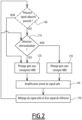
figure 2 est un organigramme d'un procédé de réception d'un signal radioélectrique selon l'invention, le procédé étant mis en oeuvre par le dispositif de réception de lafigure 1 . - Dans la suite de la description, l'expression « sensiblement égal à » s'entend comme une relation d'égalité à plus ou moins 10%, c'est-à-dire avec une variation d'au plus 10% ; de préférence encore comme une relation d'égalité à plus ou moins 5%, c'est-à-dire avec une variation d'au plus 5%.
- Sur la
figure 1 , un dispositif électronique de réception 10 est configuré pour recevoir un signal radioélectrique. Le dispositif électronique de réception 10 est typiquement un syntoniseur (de l'anglais tuner), c'est-à-dire un appareil permettant de recevoir un signal électromagnétique émis sur une bande de fréquences, de conserver la partie du signal émise sur une fréquence particulière, dite fréquence utile, et de rejeter les parties du signal émises sur les fréquences autres que la fréquence utile. - Le dispositif électronique de réception 10 est par exemple un syntoniseur analogique configuré pour syntoniser des signaux émis de façon analogique, quelle que soit la gamme d'ondes radioélectriques associée. Le syntoniseur est par exemple un syntoniseur radio, tel qu'un syntoniseur FM apte à recevoir un signal radioélectrique émis dans la gamme de fréquences comprise entre 87,5 MHz et 108 MHz ; ou un syntoniseur AM apte à recevoir un signal radioélectrique compris dans la gamme de fréquences comprise entre 148,5 kHz et 283,5 kHz et/ou entre 526,5 kHz et 1606,5 kHz ; ou un syntoniseur DAB ; ou encore un syntoniseur HD Radio. En variante, le syntoniseur est un syntoniseur TV, tel qu'un syntoniseur DVB-T ; ou un syntoniseur DVB-T 2 ; ou un syntoniseur ISDB-T ; ou encore un syntoniseur CTTB. Le syntoniseur TV est par exemple apte à recevoir un signal radioélectrique émis dans la gamme de fréquences comprise entre 40 MHz et 860 MHz.
- Le dispositif électronique de réception 10 comprend une antenne radioélectrique 12 apte à recevoir un signal radioélectrique, un amplificateur amont 14 connecté à l'antenne radioélectrique 12 et configuré pour amplifier le signal radioélectrique reçu par l'antenne 12, l'amplificateur amont 14 étant de préférence un amplificateur à gain variable, également appelé VGA (de l'anglais Variable Gain Amplifier) et comme symbolisé par la flèche associée au symbole triangulaire d'amplification sur la
figure 1 . - Le dispositif électronique de réception 10 comprend un module de pilotage 16 configuré pour piloter un gain G de l'amplificateur amont 14 et un mélangeur 18 (de l'anglais mixer) connecté en sortie de l'amplificateur amont 14, le mélangeur 18 étant configuré pour mélanger le signal issu de l'amplificateur amont 14 avec un signal de référence, tel qu'un signal issu d'un oscillateur 20 auquel est alors connecté le mélangeur 18.
- En complément, le dispositif électronique de réception 10 comprend un amplificateur aval 22 connecté en sortie du mélangeur 18 et un convertisseur analogique-numérique 24, également appelé ADC (de l'anglais Analog to Digital Converter), le convertisseur analogique-numérique 24 étant connecté en sortie de l'amplificateur aval 22.
- En complément facultatif, le dispositif électronique de réception 10 comprend un premier détecteur à large bande 26, également appelé WBD (de l'anglais Wide Band Détecter), connecté entre la sortie de l'amplificateur amont 14 et le module de pilotage 16, le premier détecteur à large bande 26 étant apte à mesurer une puissance du signal radioélectrique entre l'amplificateur amont 14 et le mélangeur 18, également appelé signal utile.
- En complément facultatif encore, le dispositif électronique de réception 10 comprend un deuxième détecteur à large bande 28 connecté entre l'antenne radioélectrique 12 et le module de pilotage 16, le deuxième détecteur à large bande 28 étant apte à mesurer la puissance du signal reçu par l'antenne 12.
- Le dispositif électronique de réception 10 est par exemple réalisé sous forme d'un ou plusieurs circuits intégrés dédiés, tels qu'un ou plusieurs ASIC (de l'anglais Application Spécifie Integrated Circuit).
- L'antenne radioélectrique 12 est connue en soi, et est de forme adaptée à la gamme d'ondes radioélectriques aptes à être reçues par le dispositif électronique de réception 10, qu'il s'agisse de la gamme radio (AM, FM, DAB, HD Radio, ISDB-Tsb) ou encore d'une gamme TV (DVB-T, DVB-T 2, ISDB-T, CTTB), décrites précédemment.
- L'amplificateur amont 14 est également connu en soi, et présente un gain G dont la valeur est apte à être pilotée par le module de pilotage 16.
- Selon l'invention, le module de pilotage 16 est configuré en outre pour effectuer une détection d'intermodulation, en commandant la génération par l'amplificateur amont 14 d'une majoration de gain ΔG et en comparant une première puissance P1 avec une deuxième puissance P2. Les première P1 et deuxième P2 puissances sont des puissances respectives du signal en sortie du mélangeur 18, c'est-à-dire du signal issu du mélangeur 18, la première puissance P1 étant mesurée en l'absence de majoration de gain de l'amplificateur amont 14, et la deuxième puissance P2 étant mesurée en présence de la majoration de gain ΔG.
- Par première puissance P1 en l'absence de majoration de gain, on entend la puissance du signal issu du mélangeur 18, par exemple mesurée via le convertisseur analogique-numérique 24, correspondant au gain par défaut de l'amplificateur amont 14, sans la majoration de gain ΔG, par exemple à un gain nominal, noté Gnom. Selon ce dernier exemple, la première puissance P1 est alors également notée P(Gnom), ou encore PADC(Gnom) lorsqu'elle est mesurée via le convertisseur analogique-numérique 24, également appelé ADC.
- Par deuxième puissance P2 en présence de la majoration de gain ΔG, on entend la puissance du signal issu du mélangeur 18, par exemple mesurée via le convertisseur analogique-numérique 24, correspondant au même gain par défaut de l'amplificateur amont 14 avec en outre la majoration de gain ΔG, c'est-à-dire correspond à la somme dudit gain par défaut et de la majoration de gain ΔG. Dans l'exemple où ledit gain par défaut est le gain nominal Gnom, la deuxième puissance P2 est alors également notée P(Gnom+ΔG), ou encore PADC(Gnom+ΔG) lorsqu'elle est mesurée via le convertisseur analogique-numérique 24, également appelé ADC.
- Les première et deuxième puissances P1, P2 sont par exemple mesurées par le convertisseur analogique numérique 24, et le module de pilotage 16 est alors relié audit convertisseur analogique numérique 24.
- Le module de pilotage 16 est par exemple configuré pour détecter une intermodulation, c'est-à-dire pour considérer qu'une intermodulation est présente, si une différence entre la deuxième puissance P2 et la première puissance P1 est supérieure à sensiblement 1,5 fois la majoration de gain ΔG. Autrement dit, dans cet exemple, lorsque les première P1 et deuxième P2 puissances, ainsi que la majoration de gain ΔG, sont exprimées en décibels, une intermodulation est détectée si la différence entre la deuxième puissance P2 et la première puissance P1 est sensiblement supérieure à ΔG+2dB.
- Selon cet exemple, une intermodulation est alors détectée si l'inéquation suivante est vérifiée :

- avec P1 = P(Gnom), par exemple P1 = PADC(Gnom),
- P2 = P(Gnom+ΔG), par exemple P2 = PADC(Gnom+ΔG),
- P1 et P2 étant exprimées en dB.
- De préférence, une intermodulation est détectée si l'inéquation suivante est vérifiée :

- avec P1 = P(Gnom), par exemple P1 = PADC(Gnom),
- P2 = P(Gnom+ΔG), par exemple P2 = PADC(Gnom+ΔG),
- P1 et P2 étant exprimées en dB.
- La majoration de gain ΔG est de préférence de courte durée afin de perturber le moins possible le signal délivré en sortie du dispositif de réception 10. La majoration de gain ΔG est par exemple une impulsion de gain ayant une brève durée, telle qu'une durée inférieure à 100 µs, de préférence sensiblement égale à 50 µs.
- La majoration de gain ΔG est de préférence supérieure à la valeur par défaut du gain G. La majoration de gain ΔG dépend d'une amplitude du signal radioélectrique reçu et d'une amplitude maximale du signal avant saturation du dispositif électronique de réception 10, en particulier avant saturation du convertisseur analogique-numérique 24. L'amplitude de la majoration de gain ΔG est par exemple égale à la différence entre ladite amplitude maximale avant saturation et l'amplitude du signal radioélectrique reçu.
- Le module de pilotage 16 est configuré pour commander répétitivement la génération de la majoration de gain ΔG.
- L'homme du métier comprendra que par répétitivement, on entend une réitération à intervalle temporel successif, la génération répétitive de la majoration de gain ΔG étant de préférence sensiblement périodique, avec par exemple une périodicité sensiblement égale à 1 ms, tant qu'aucune modulation n'a été détectée et tant que le gain de l'amplificateur amont 14 est inférieur au gain maximal amont prédéfini Gmax.
- En complément, le module de pilotage 16 est configuré pour augmenter l'écart temporel entre une nouvelle majoration de gain ΔGn+1 générée à un instant temporel tn+1 et une dernière majoration de gain ΔGn générée à un instant temporel tn en cas de détection d'une intermodulation suite à la dernière majoration de gain ΔGn. Autrement dit, en cas de détection d'une intermodulation, le module de pilotage 16 est alors configuré pour espacer temporellement la prochaine majoration de gain ΔGn+1 par rapport à la dernière majoration de gain ΔGn ayant engendré la détection de cette intermodulation. Ceci permet de limiter d'éventuelles oscillations du signal utile, et d'éviter que la détection d'intermodulation n'engendre une perturbation du signal délivré en sortie du dispositif de réception 10.
- L'écart temporel entre deux majorations successives de gain ΔGn, ΔGn+1, c'est-à-dire la différence temporelle entre les instants temporels tn et tn+1, est par exemple sensiblement égale à 1 ms si aucune intermodulation n'a été détectée suite à la dernière majoration de gain ΔGn et si le gain G de l'amplificateur amont 14 est inférieur à un gain maximal amont prédéfini Gmax.
- Si une intermodulation a été détectée suite à la dernière majoration de gain ΔGn, alors l'écart temporel entre l'instant temporel tn de génération de la dernière majoration de gain ΔGn et l'instant temporel tn+1 de génération de la prochaine majoration de gain ΔGn+1 est par exemple sensiblement égal à 20 ms.
- Si le gain G de l'amplificateur amont 14 est sensiblement égal au gain maximal amont prédéfini Gmax, alors l'écart temporel entre deux instants temporels successifs tn, tn+1 de majorations successives de gain ΔGn, ΔGn+1 est supérieur à celui faisant suite à une détection d'intermodulation, et est par exemple sensiblement égal à 50 ms.
- Autrement dit, pour effectuer une détection d'intermodulation, le module de pilotage 16 est configuré pour augmenter sur une brève durée, et de préférence répétitivement, le gain de l'amplification amont et pour mesurer ensuite l'augmentation de puissance sur le signal issu du mélangeur 18. Si l'augmentation de puissance est du même ordre que la variation de l'amplification, c'est-à-dire si la variation de la puissance du signal issu du mélangeur en fonction de la variation du gain est sensiblement linéaire, alors le module de pilotage 16 considère que le dispositif de réception 10 n'est pas en situation d'intermodulation. Au contraire, si l'augmentation de puissance est très supérieure à la variation de gain de l'amplification amont, le module de pilotage 16 considère qu'une intermodulation est présente.
- Le module de pilotage 16 est configuré en outre pour appliquer ou non des consignes issues du premier détecteur à large bande 26, et en complément facultatif du deuxième détecteur à large bande 28, en fonction de la détection ou non d'une intermodulation. Plus précisément, si le module de pilotage 16 considère qu'aucune intermodulation n'est présente, alors il est configuré pour ignorer les consignes issues du ou des détecteurs à large bande 26, 28. Sinon, si le module de pilotage 16 considère qu'une intermodulation est présente, il est alors configuré pour appliquer chaque consigne de modification de gain issue du ou des détecteurs à large bande 26, 28.
- En complément facultatif, le module de pilotage 16 est en outre configuré pour, préalablement à la détection d'intermodulation, effectuer un test de présence d'au moins un signal adjacent parasite, par exemple d'au moins un signal adjacent fort. Le module de pilotage 16 est alors configuré pour effectuer la détection d'intermodulation seulement si le test de présence est positif, c'est-à-dire si au moins un signal adjacent parasite est considéré comme présent, ledit test de présence dépendant de la puissance du signal en sortie du mélangeur 18 et du gain G de l'amplificateur amont 14.
- Le test de présence est par exemple positif si le gain G de l'amplificateur amont est inférieur au gain maximal amont prédéfini Gmax, de préférence très inférieur audit gain maximal amont prédéfini Gmax, et si la puissance du signal en sortie du mélangeur 18, par exemple mesurée par le convertisseur analogique-numérique 24, est strictement inférieure à une puissance cible prédéfinie Pc. Le test de présence est négatif si les conditions précitées ne sont pas remplies.
- Par gain très inférieur audit gain maximal amont prédéfini Gmax, on entend par exemple un gain inférieur d'au moins 2dB par rapport audit gain maximal amont prédéfini Gmax. Par puissance inférieure à la puissance cible prédéfinie Pc, on entend par exemple une puissance de 2dB en-dessous de ladite puissance cible Pc.
- La détermination de la puissance cible prédéfinie Pc est connue en soi, et la puissance cible prédéfinie Pc est par exemple déterminée en fonction de la forme d'onde à démoduler et également d'un PAPR (de l'anglais Peak to Average Power Ratio) de la forme d'onde pour avoir le maximum de dynamique au niveau du convertisseur analogique-numérique 24 sans provoquer de saturation.
- En complément facultatif, notamment si le dispositif de réception comprend en outre l'amplificateur aval 22 connecté en sortie du mélangeur 18, le test de présence d'au moins un signal adjacent parasite dépend en outre d'un gain Γ de l'amplificateur aval 22.
- Selon ce complément facultatif, le test de présence est par exemple positif si la puissance du signal en sortie du mélangeur 18 est inférieure à la puissance cible prédéfinie Pc et si le gain G de l'amplificateur amont 14 est inférieur au gain maximal amont prédéfini Gmax et en outre si le gain Γ de l'amplificateur aval 22 est sensiblement égal à un gain maximal aval prédéfini Γmax.
- Le choix du gain maximal amont prédéfini Gmax, et le cas échéant du gain maximal aval prédéfini Γmax, sont connus en soi. Chaque gain maximal prédéfini Gmax, Γmax est dépendant de l'amplificateur concerné, et est qualifié sur le dispositif de réception 10 dans lequel est implémenté l'invention. Par exemple, pour un tuner silicium, le gain maximal amont prédéfini Gmax est sensiblement égal à 40dB, le gain maximal aval prédéfini Γmax est sensiblement égal à 25dB.
- Le mélangeur 18 est connu en soi et est configuré pour mélanger le signal issu de l'amplificateur amont 14 - dit signal utile - avec le signal de référence, par exemple en multipliant ces deux signaux, la tension du signal en sortie du mélangeur étant alors le produit de la tension du signal utile et de la tension du signal de référence.
- Le signal de référence est typiquement un signal non-modulé, par exemple un signal provenant de l'oscillateur local 20, et le mélangeur 18 est alors connecté à l'oscillateur local 20.
- L'oscillateur local 20 est apte à fournir le signal de référence, tel que le signal non-modulé, ce signal non-modulé permettant, via le mélangeur 18, la transposition du signal utile vers une fréquence intermédiaire.
- L'amplificateur aval 22 est connu en soi, et est adapté pour amplifier le signal issu du mélangeur 18.
- Le convertisseur analogique-numérique 24 est connecté en sortie de l'amplificateur aval 22 lorsqu'il est présent, ou bien directement en sortie du mélangeur 18 en l'absence d'amplificateur aval, et est configuré pour convertir le signal analogique issu du mélangeur 18, éventuellement amplifié par l'amplificateur aval 22, en un signal numérique.
- En complément facultatif, le convertisseur analogique-numérique 24 est configuré en outre pour mesurer la puissance du signal issu du mélangeur 18, notamment la première puissance P1 en l'absence de majoration de gain, puis la deuxième puissance P2 en présence de la majoration de gain ΔG.
- Chaque détecteur à large bande 26, 28 est connu en soi, et est apte à réguler l'amplification effectuée par l'amplificateur amont 14 en mesurant la puissance du signal issu de l'amplificateur amont 14 pour le premier détecteur à large bande 26, voire en mesurant la puissance du signal issu de l'antenne radioélectrique 12 pour le deuxième détecteur à large bande 28 lorsqu'il est présent, et en générant une consigne de gain afin de réguler la puissance si la puissance mesurée est en dehors d'une plage de puissances prédéfinie. Autrement dit, chaque détecteur à large bande 26, 28 vise à empêcher une amplification trop importante du signal radioélectrique par l'amplificateur amont 14, et plus généralement à limiter l'introduction par l'amplificateur amont 14 d'une non-linéarité sur le signal reçu.
- Le fonctionnement du dispositif électronique de réception 10 va désormais être expliqué à l'aide de la
figure 2 représentant un organigramme du procédé, selon l'invention, de réception d'un signal radioélectrique. - Lors d'une étape initiale 100 facultative, le dispositif de réception 10 effectue, via son module de pilotage 16, un test de présence d'au moins un signal adjacent parasite à partir de la puissance du signal en sortie du mélangeur 18 et du gain G de l'amplificateur amont 14, voire à partir en outre du gain Γ de l'amplificateur aval 22.
- Le test de présence est par exemple positif si le gain G de l'amplificateur amont 14 est très inférieur au gain maximal amont prédéfini Gmax et si la puissance du signal en sortie du mélangeur 18 est strictement inférieure à la puissance cible prédéfinie Pc, le test de présence étant négatif autrement.
- En variante, le test de présence est positif si le gain G de l'amplificateur amont 14 est inférieur au gain maximal amont prédéfini Gmax, et si le gain Γ de l'amplificateur aval 22 est sensiblement égal au gain maximal aval prédéfini Γmax, et en outre si la puissance P du signal en sortie du mélangeur 18 est inférieure à la puissance cible prédéfinie Pc, le test de présence étant négatif autrement.
- Si le test de présence effectué à l'étape initiale 100 est positif, alors le dispositif de réception 10 passe à l'étape suivante 110 au cours de laquelle il effectue, via son module de pilotage 16, une détection d'une éventuelle intermodulation. Cette détection d'intermodulation comporte la génération par l'amplificateur amont 14 de la majoration de gain ΔG, puis la comparaison des première et deuxième puissances P1, P2 du signal issu du mélangeur 18, la première puissance P1 étant mesurée en l'absence de majoration de gain et la deuxième puissance P2 étant mesurée en présence de la majoration de gain ΔG.
- Lors de cette étape 110, le module de pilotage 16 considère alors qu'une intermodulation est présente lorsque la variation de la puissance P du signal en sortie du mélangeur 18, correspondant à la différence entre la deuxième puissance P2 et la première puissance P1, est non-linéaire par rapport à la majoration de gain ΔG, typiquement si la différence entre la deuxième puissance P2 et la première puissance P1 est supérieure à sensiblement 1,5 fois la majoration de gain ΔG. A titre d'exemple, si la variation de puissance P2-P1 vérifie l'inéquation (1) ou (2), alors le module de pilotage 16 considère qu'une intermodulation 16 est présente. Sinon, c'est-à-dire si la variation de puissance P2-P1 est sensiblement linéaire par rapport à la majoration de gain ΔG, par exemple si les inéquations (1) ou (2) ne sont pas vérifiées, alors le module de pilotage 16 considère qu'aucune intermodulation n'est détectée.
- Si la détection d'intermodulation effectuée lors de l'étape 110 est positive, c'est-à-dire si le module de pilotage 16 considère qu'une intermodulation est présente, alors le dispositif de réception 10 passe à l'étape 120 au cours de laquelle le module de pilotage 16 pilote le gain G de l'amplificateur amont 14 en tenant compte d'éventuelles consignes de modification du gain G issues du ou des détecteurs à large bande 26, 28.
- Sinon, si la détection d'intermodulation est négative, c'est-à-dire si le module de pilotage 16 considère lors de l'étape 110 qu'aucune intermodulation n'est présente, alors le dispositif de réception 10 passe à l'étape 130 au cours de laquelle le module de pilotage 16 pilote le gain G de l'amplificateur amont 14 en ignorant d'éventuelles consignes issues du ou des détecteurs à large bande 26, 28.
- Si à l'issue de l'étape initiale et facultative 100 de test de la présence d'au moins un signal adjacent parasite, le test est négatif, c'est-à-dire si aucun signal adjacent parasite n'est détecté, alors le dispositif de réception 10 passe directement de l'étape 100 à l'étape 120 de pilotage du gain pour tenir compte d'éventuelles consignes de modification du gain G issues du ou des détecteurs à large bande 26, 28.
- L'homme du métier comprendra bien entendu que lorsque le dispositif de réception 10 n'effectue pas l'étape initiale 100 facultative, alors il débute le procédé de réception directement à l'étape 110.
- A l'issue de l'étape 120 de pilotage du gain avec prise en compte de consigne(s) WBD ou bien à l'issue de l'étape 130 de pilotage du gain sans prise en compte de consigne(s) WBD, le dispositif de réception 10 amplifie ensuite, lors de l'étape 140, le signal radioélectrique reçu via son amplificateur amont 14.
- Le dispositif de réception 10 mélange ensuite, lors de l'étape 150, le signal issu de l'amplificateur amont 14, dit signal utile, avec le signal de référence, de préférence non-modulé, via son mélangeur 18, et le signal analogique issu du mélangeur 18 est ensuite converti en le signal numérique par le convertisseur analogique-numérique 24.
- Ce signal numérique converti par le convertisseur analogique-numérique 24 correspond au signal fourni en sortie du dispositif de réception 10. Le signal ainsi converti par le convertisseur analogique-numérique 24 est ensuite typiquement filtré numériquement, au besoin rééchantillonné (adaptation de la fréquence d'échantillonnage dans le cas de signaux numériques), et démodulé par un récepteur placé en sortie du dispositif de réception. Le signal démodulé devient alors un signal audio et/ou vidéo destiné à être reproduit par un dispositif tiers (autoradio, TV, etc.).
- Le procédé de réception retourne ensuite à l'étape 100 ou à l'étape 110 selon que l'étape initiale 100 optionnelle est effectuée ou non, afin d'effectuer la réception d'un nouveau signal radioélectrique.
- Ainsi, le dispositif électronique de réception 10 selon l'invention permet d'effectuer, plus simplement et via le module de pilotage 16, une détection d'une éventuelle intermodulation, en commandant la génération par l'amplificateur amont 14 de la majoration de gain ΔG, puis en observant si la variation de puissance du signal issu du mélangeur 18, résultant de cette majoration de gain ΔG, est une variation sensiblement linéaire, ou au contraire une variation non-linéaire, par rapport à la majoration de gain ΔG générée. Une intermodulation est alors considérée comme présente, si la variation de puissance P2-P1 du signal en sortie du mélangeur 18 est non-linéaire par rapport à la majoration de gain ΔG. Corolairement, aucune intermodulation n'est considérée comme présente, si la variation de puissance P2-P1 est sensiblement linéaire par rapport à la majoration de gain ΔG générée.
- La génération par l'amplificateur amont 14 de la majoration de gain ΔG est de préférence commandée de manière répétitive par le module de pilotage 16 afin d'effectuer cette détection d'intermodulation à intervalles temporels successifs.
- L'écart temporel entre deux instants successifs tn, tn+1 de génération de deux majorations successives de gain ΔGn, ΔGn+1 dépend en outre de préférence de la détection ou non d'une intermodulation suite à la dernière majoration de gain ΔGn et de la valeur du gain G de l'amplificateur amont 14 par rapport au gain maximal amont prédéfini Gmax, ce qui permet de limiter le risque d'introduction d'éventuelles oscillations dues à cette détection d'intermodulation, et qui seraient alors potentiellement perturbatrices du signal délivré en sortie du dispositif de réception 10.
- La génération de la majoration de gain ΔG est alors par exemple commandée de manière périodique avec une périodicité temporelle relativement faible, typiquement avec une période temporelle sensiblement égale à 1 ms, seulement si aucune intermodulation n'a été détectée suite à la dernière majoration de gain ΔGn et si le gain G de l'amplificateur amont 14 est inférieur au gain maximal amont prédéfini Gmax. Autrement, si le gain G de l'amplificateur amont 14 est sensiblement égal au gain maximal amont prédéfini Gmax, alors l'écart temporel entre une prochaine majoration de gain ΔGn+1 et la majoration de gain précédente ΔGn est nettement augmenté, typiquement sensiblement égal à 50 ms. De manière analogue, si une intermodulation a été détectée suite à la dernière majoration de gain ΔGn, alors l'écart temporel entre la prochaine majoration de gain ΔGn+1 et la dernière majoration de gain ΔGn est également augmenté, cette augmentation étant toutefois moindre, l'écart temporal étant alors typiquement sensiblement égal à 20 ms, que dans le cas où le gain G de l'amplificateur amont 14 est sensiblement égal au gain maximal amont prédéfini Gmax.
- Le fait d'effectuer en complément facultatif un test de présence d'au moins un signal adjacent parasite, tel qu'au moins un signal adjacent fort, permet en outre d'effectuer la détection d'intermodulation seulement si celle-ci est nécessaire. En effet, si aucun signal adjacent parasite n'est détecté, il n'est alors pas nécessaire d'effectuer ensuite une détection d'intermodulation, et le procédé de réception passe alors directement dans ce cas de l'étape 100 à l'étape 120.
- On conçoit ainsi que le dispositif électronique de réception 10 selon l'invention permet d'effectuer la détection d'une éventuelle intermodulation de manière plus simple qu'avec un dispositif électronique de réception de l'état de la technique.
Claims (11)
- Dispositif électronique (10) de réception d'un signal radioélectrique, le dispositif (10) comprenant :- un amplificateur amont (14) configuré pour amplifier un signal radioélectrique reçu,- un module de pilotage (16) configuré pour piloter un gain (G) de l'amplificateur amont (14), et- un mélangeur (18) connecté en sortie de l'amplificateur amont (14), le mélangeur (18) étant configuré pour mélanger le signal issu de l'amplificateur amont (14) avec un signal de référence,caractérisé en ce que le module de pilotage (16) est configuré en outre pour effectuer une détection d'intermodulation, en commandant la génération par l'amplificateur amont (14) d'une majoration de gain (ΔG) et en comparant une première puissance (P1) avec une deuxième puissance (P2), les première et deuxième puissances (P1, P2) étant des puissances respectives d'un signal en sortie du mélangeur (18), la première puissance (P1) étant mesurée en l'absence de majoration de gain et la deuxième puissance (P2) étant mesurée en présence de la majoration de gain (ΔG),le module de pilotage (16) étant configuré pour commander répétitivement la génération de la majoration de gain (ΔG),l'écart temporel entre une nouvelle majoration de gain et la dernière majoration de gain (ΔGn) étant augmenté en cas de détection d'une intermodulation suite à la dernière majoration de gain (ΔGn).
- Dispositif (10) selon la revendication 1, dans lequel une intermodulation est détectée si une différence entre la deuxième puissance (P2) et la première puissance (P1) est supérieure à sensiblement 1,5 fois la majoration de gain (ΔG).
- Dispositif (10) selon la revendication 1 ou 2, dans lequel l'écart temporel entre deux majorations successives de gain est sensiblement égal à 1 ms si aucune intermodulation n'a été détectée suite à la dernière majoration de gain (ΔGn) et si le gain (G) de l'amplificateur amont (14) est inférieur à un gain maximal amont prédéfini (Gmax).
- Dispositif (10) selon l'une quelconque des revendications précédentes, dans lequel le dispositif (10) comprend en outre un amplificateur aval (22) connecté en sortie du mélangeur (18) et un convertisseur analogique-numérique (24) connecté en sortie de l'amplificateur aval (22),
le convertisseur analogique-numérique (24) étant de préférence configuré pour mesurer les première et deuxième puissances (P1, P2). - Dispositif (10) selon l'une quelconque des revendications précédentes, dans lequel le module de pilotage (16) est en outre configuré pour, préalablement à une détection d'intermodulation, effectuer un test de présence d'au moins un signal adjacent parasite, et pour effectuer alors la détection d'intermodulation seulement si le test de présence est positif, ledit test de présence dépendant de la puissance du signal en sortie du mélangeur (18) et du gain (G) de l'amplificateur amont (14).
- Dispositif (10) selon la revendication 5, dans lequel le test de présence est positif si le gain (G) de l'amplificateur amont (14) est inférieur à un gain maximal amont prédéfini (Gmax) et si la puissance du signal en sortie du mélangeur (18) est strictement inférieure à une puissance cible prédéfinie (Pc).
- Dispositif (10) selon les revendications 4 et 5, dans lequel le test de présence dépend en outre d'un gain (Γ) de l'amplificateur aval (22),
le test de présence étant de préférence positif si le gain (G) de l'amplificateur amont (14) est inférieur à un gain maximal amont prédéfini (Gmax), si le gain (Γ) de l'amplificateur aval (22) est sensiblement égal à un gain maximal aval prédéfini (Γmax) et si la puissance du signal en sortie du mélangeur (18) est inférieure à une puissance cible prédéfinie (Pc). - Dispositif (10) selon l'une quelconque des revendications précédentes, dans lequel le dispositif (10) comprend en outre un premier détecteur à large bande (26) connecté entre la sortie de l'amplificateur amont (14) et le module de pilotage (16).
- Dispositif (10) selon l'une quelconque des revendications précédentes, dans lequel le dispositif (10) comprend en outre une antenne radioélectrique (12) apte à recevoir un signal radioélectrique, et un deuxième détecteur à large bande (28) connecté entre l'antenne radioélectrique (12) et le module de pilotage (16).
- Circuit intégré implémentant un dispositif électronique (10) de réception d'un signal radioélectrique, caractérisé en ce que le dispositif (10) est selon l'une quelconque des revendications précédentes.
- Procédé de réception d'un signal radioélectrique, le procédé étant mis en oeuvre par un dispositif électronique de réception (10) et comprenant les étapes consistant à :- piloter un gain d'un amplificateur amont (14), et- amplifier, via l'amplificateur amont (14), un signal radioélectrique reçu,- mélanger le signal issu de l'amplificateur amont (14) avec un signal de référence, caractérisé en ce que le procédé comprend en outre l'étape consistant à :- effectuer une détection d'intermodulation, en commandant la génération par l'amplificateur amont (14) d'une majoration de gain (ΔG) et en comparant une première puissance (P1) avec une deuxième puissance (P2), les première et deuxième puissances (P1, P2) étant des puissances respectives d'un signal en sortie du mélangeur (18), la première puissance (P1) étant mesurée en l'absence de majoration de gain et la deuxième puissance (P2) étant mesurée en présence de la majoration de gain (ΔG),la génération de la majoration de gain (ΔG) étant commandée répétitivement,si une intermodulation a été détectée suite à la dernière majoration de gain (ΔGn), alors l'écart temporel entre une nouvelle majoration de gain et la dernière majoration de gain (ΔGn) est augmenté.
Applications Claiming Priority (1)
| Application Number | Priority Date | Filing Date | Title |
|---|---|---|---|
| FR1860197A FR3088157A1 (fr) | 2018-11-06 | 2018-11-06 | Dispositif electronique et procede de reception d'un signal radioelectrique, circuit integre implementant un tel dispositif |
Publications (2)
| Publication Number | Publication Date |
|---|---|
| EP3651369A1 EP3651369A1 (fr) | 2020-05-13 |
| EP3651369B1 true EP3651369B1 (fr) | 2023-08-16 |
Family
ID=65951657
Family Applications (1)
| Application Number | Title | Priority Date | Filing Date |
|---|---|---|---|
| EP19207043.1A Active EP3651369B1 (fr) | 2018-11-06 | 2019-11-05 | Dispositif électronique et procédé de réception d'un signal radioélectrique, circuit intégré implémentant un tel dispositif |
Country Status (5)
| Country | Link |
|---|---|
| US (1) | US10985723B2 (fr) |
| EP (1) | EP3651369B1 (fr) |
| JP (1) | JP7578395B2 (fr) |
| CN (1) | CN111147094B (fr) |
| FR (1) | FR3088157A1 (fr) |
Family Cites Families (19)
| Publication number | Priority date | Publication date | Assignee | Title |
|---|---|---|---|---|
| US5107225A (en) | 1990-11-30 | 1992-04-21 | Qualcomm Incorporated | High dynamic range closed loop automatic gain control circuit |
| US5722063A (en) * | 1994-12-16 | 1998-02-24 | Qualcomm Incorporated | Method and apparatus for increasing receiver immunity to interference |
| KR100222404B1 (ko) * | 1997-06-21 | 1999-10-01 | 윤종용 | 혼변조 왜곡 성분을 억압하는 수신장치 및 방법 |
| US6134430A (en) * | 1997-12-09 | 2000-10-17 | Younis; Saed G. | Programmable dynamic range receiver with adjustable dynamic range analog to digital converter |
| US6489847B1 (en) * | 2000-01-28 | 2002-12-03 | Telefonaktiebolaget Lm Ericsson | Low distoration driving amplifier for integrated filters |
| US6670901B2 (en) * | 2001-07-31 | 2003-12-30 | Motorola, Inc. | Dynamic range on demand receiver and method of varying same |
| US7120410B2 (en) * | 2001-09-28 | 2006-10-10 | Broadcom Corporation | LNA gain adjustment in an RF receiver to compensate for intermodulation interference |
| US20030064965A1 (en) * | 2001-10-02 | 2003-04-03 | Jacob Richter | Method of delivering drugs to a tissue using drug-coated medical devices |
| US7299021B2 (en) * | 2001-12-28 | 2007-11-20 | Nokia Corporation | Method and apparatus for scaling the dynamic range of a receiver for continuously optimizing performance versus power consumption |
| US6961552B2 (en) * | 2002-03-25 | 2005-11-01 | Broadcom Corporation | LNA gain adjustment for intermodulation interference reduction |
| US20040043733A1 (en) | 2002-08-27 | 2004-03-04 | Delphi Technologies, Inc. | Enhanced automatic gain control |
| DE602004021677D1 (de) * | 2003-03-28 | 2009-08-06 | Nxp Bv | Integrierter tuner |
| FR2871629A1 (fr) * | 2004-06-09 | 2005-12-16 | Thomson Licensing Sa | Dispositif de conversion de frequences, procede d'etalonnage dudit dispositif et systeme d'emission/reception de signaux electromagnetiques comportant un tel dispositif |
| US7426376B2 (en) * | 2005-06-30 | 2008-09-16 | Silicon Laboratories Inc. | Receiver having digital automatic gain control |
| US20080102773A1 (en) | 2006-10-31 | 2008-05-01 | Motorola, Inc. | Method and apparatus to facilitate use of intermodulation product results to control gain for a received wireless signal |
| US7693501B2 (en) | 2006-12-21 | 2010-04-06 | Intel Corporation | Techniques to deterministically reduce signal interference |
| JP6220221B2 (ja) * | 2013-10-28 | 2017-10-25 | ルネサスエレクトロニクス株式会社 | 受信機、半導体集積回路及び利得制御方法 |
| GB2533300B (en) * | 2014-12-15 | 2017-03-22 | Nordic Semiconductor Asa | Packet-based radio receiver with automatic gain control |
| US9641128B2 (en) * | 2015-07-29 | 2017-05-02 | Qualcomm Incorporated | High linearity structure for amplifier |
-
2018
- 2018-11-06 FR FR1860197A patent/FR3088157A1/fr not_active Withdrawn
-
2019
- 2019-11-04 CN CN201911065771.8A patent/CN111147094B/zh active Active
- 2019-11-05 JP JP2019200978A patent/JP7578395B2/ja active Active
- 2019-11-05 EP EP19207043.1A patent/EP3651369B1/fr active Active
- 2019-11-06 US US16/676,113 patent/US10985723B2/en active Active
Also Published As
| Publication number | Publication date |
|---|---|
| EP3651369A1 (fr) | 2020-05-13 |
| US10985723B2 (en) | 2021-04-20 |
| CN111147094B (zh) | 2023-06-30 |
| JP2020078076A (ja) | 2020-05-21 |
| US20200144980A1 (en) | 2020-05-07 |
| CN111147094A (zh) | 2020-05-12 |
| JP7578395B2 (ja) | 2024-11-06 |
| FR3088157A1 (fr) | 2020-05-08 |
Similar Documents
| Publication | Publication Date | Title |
|---|---|---|
| EP1642433B1 (fr) | Methode d'estimation de residu de la porteuse, estimateur et systeme de modulation avec asservissement de la porteuse l'utilisant | |
| EP0093651A1 (fr) | Récepteur de signaux multiporteuses protégé des signaux perturbateurs | |
| EP0657997B1 (fr) | Procédé de commande automatique de gain dans un récepteur radio numérique et récepteur mettant en oeuvre ce procédé | |
| FR2991527A1 (fr) | Procede de calibration de lineariseur et composant electronique linearise | |
| EP2533426B1 (fr) | Système de réception comprenant un mécanisme contre les interférences pulsées | |
| KR20070119612A (ko) | 자동 이득 제어 전환-포인트의 동적 제어를 위한 시스템 및동작 방법 | |
| EP3651369A1 (fr) | Dispositif électronique et procédé de réception d'un signal radioélectrique, circuit intégré implémentant un tel dispositif | |
| US8055232B2 (en) | Radio frequency receiving apparatus, radio frequency receiving method, LSI for radio frequency signal and LSI for base band signal | |
| FR2833429A1 (fr) | Procede de controle du gain d'un syntonisateur de frequences, et syntonisateur correspondant, en particulier pour la reception de signaux de television numerique terrestre | |
| EP0604295B1 (fr) | Procédé de contrÔle automatique de gain pour un récepteur numérique, notamment un récepteur à accès multiple à répartition dans le temps et dispositif pour sa mise en oeuvre | |
| US7907923B2 (en) | Method and apparatus for squelch gating a receiving signal | |
| TWI376873B (fr) | ||
| WO2003001689A2 (fr) | Systeme d'amplification d'un signal hertzien et decodeur de signaux de television comportant un tel systeme | |
| FR3060915A1 (fr) | Controle du spectre d'une emission rf impulsionnelle par mise en forme des impulsions | |
| EP4498608A1 (fr) | Radio logicielle equipée d'une protection de son amplificateur de puissance | |
| EP0959630B1 (fr) | Dispositif de régulation de l'amplitude du signal chrominance | |
| JP2005192060A (ja) | 自動利得制御装置 | |
| US8451376B1 (en) | Automatic gain control (AGC) for analog TV signals using feed-forward signal path delay | |
| JPH05291986A (ja) | 自動利得制御回路 | |
| JP2008124537A (ja) | 高周波増幅器 | |
| KR0176633B1 (ko) | 디지탈 텔레비젼 수상기의 2중 자동 이득 조절회로 | |
| EP2196788B1 (fr) | Radiomètre et procédé de mesure de température de scène radiométrique en mode pulsé | |
| US12556151B1 (en) | Digital control of analog amplification gain in a receiver device | |
| EP2066023B1 (fr) | Amplificateur HF large bande comportant un système de réduction de distorsion et procédé de réduction de distorsion associé | |
| KR100628139B1 (ko) | 자동 이득 제어 장치 및 방법 |
Legal Events
| Date | Code | Title | Description |
|---|---|---|---|
| PUAI | Public reference made under article 153(3) epc to a published international application that has entered the european phase |
Free format text: ORIGINAL CODE: 0009012 |
|
| STAA | Information on the status of an ep patent application or granted ep patent |
Free format text: STATUS: THE APPLICATION HAS BEEN PUBLISHED |
|
| AK | Designated contracting states |
Kind code of ref document: A1 Designated state(s): AL AT BE BG CH CY CZ DE DK EE ES FI FR GB GR HR HU IE IS IT LI LT LU LV MC MK MT NL NO PL PT RO RS SE SI SK SM TR |
|
| AX | Request for extension of the european patent |
Extension state: BA ME |
|
| STAA | Information on the status of an ep patent application or granted ep patent |
Free format text: STATUS: REQUEST FOR EXAMINATION WAS MADE |
|
| 17P | Request for examination filed |
Effective date: 20201014 |
|
| RBV | Designated contracting states (corrected) |
Designated state(s): AL AT BE BG CH CY CZ DE DK EE ES FI FR GB GR HR HU IE IS IT LI LT LU LV MC MK MT NL NO PL PT RO RS SE SI SK SM TR |
|
| STAA | Information on the status of an ep patent application or granted ep patent |
Free format text: STATUS: EXAMINATION IS IN PROGRESS |
|
| 17Q | First examination report despatched |
Effective date: 20211115 |
|
| GRAP | Despatch of communication of intention to grant a patent |
Free format text: ORIGINAL CODE: EPIDOSNIGR1 |
|
| STAA | Information on the status of an ep patent application or granted ep patent |
Free format text: STATUS: GRANT OF PATENT IS INTENDED |
|
| INTG | Intention to grant announced |
Effective date: 20230330 |
|
| GRAS | Grant fee paid |
Free format text: ORIGINAL CODE: EPIDOSNIGR3 |
|
| GRAA | (expected) grant |
Free format text: ORIGINAL CODE: 0009210 |
|
| STAA | Information on the status of an ep patent application or granted ep patent |
Free format text: STATUS: THE PATENT HAS BEEN GRANTED |
|
| AK | Designated contracting states |
Kind code of ref document: B1 Designated state(s): AL AT BE BG CH CY CZ DE DK EE ES FI FR GB GR HR HU IE IS IT LI LT LU LV MC MK MT NL NO PL PT RO RS SE SI SK SM TR |
|
| REG | Reference to a national code |
Ref country code: CH Ref legal event code: EP Ref country code: DE Ref legal event code: R096 Ref document number: 602019035002 Country of ref document: DE |
|
| REG | Reference to a national code |
Ref country code: IE Ref legal event code: FG4D Free format text: LANGUAGE OF EP DOCUMENT: FRENCH |
|
| REG | Reference to a national code |
Ref country code: LT Ref legal event code: MG9D |
|
| REG | Reference to a national code |
Ref country code: NL Ref legal event code: MP Effective date: 20230816 |
|
| REG | Reference to a national code |
Ref country code: AT Ref legal event code: MK05 Ref document number: 1601051 Country of ref document: AT Kind code of ref document: T Effective date: 20230816 |
|
| PG25 | Lapsed in a contracting state [announced via postgrant information from national office to epo] |
Ref country code: GR Free format text: LAPSE BECAUSE OF FAILURE TO SUBMIT A TRANSLATION OF THE DESCRIPTION OR TO PAY THE FEE WITHIN THE PRESCRIBED TIME-LIMIT Effective date: 20231117 |
|
| PG25 | Lapsed in a contracting state [announced via postgrant information from national office to epo] |
Ref country code: IS Free format text: LAPSE BECAUSE OF FAILURE TO SUBMIT A TRANSLATION OF THE DESCRIPTION OR TO PAY THE FEE WITHIN THE PRESCRIBED TIME-LIMIT Effective date: 20231216 |
|
| PG25 | Lapsed in a contracting state [announced via postgrant information from national office to epo] |
Ref country code: SE Free format text: LAPSE BECAUSE OF FAILURE TO SUBMIT A TRANSLATION OF THE DESCRIPTION OR TO PAY THE FEE WITHIN THE PRESCRIBED TIME-LIMIT Effective date: 20230816 Ref country code: RS Free format text: LAPSE BECAUSE OF FAILURE TO SUBMIT A TRANSLATION OF THE DESCRIPTION OR TO PAY THE FEE WITHIN THE PRESCRIBED TIME-LIMIT Effective date: 20230816 Ref country code: PT Free format text: LAPSE BECAUSE OF FAILURE TO SUBMIT A TRANSLATION OF THE DESCRIPTION OR TO PAY THE FEE WITHIN THE PRESCRIBED TIME-LIMIT Effective date: 20231218 Ref country code: NO Free format text: LAPSE BECAUSE OF FAILURE TO SUBMIT A TRANSLATION OF THE DESCRIPTION OR TO PAY THE FEE WITHIN THE PRESCRIBED TIME-LIMIT Effective date: 20231116 Ref country code: NL Free format text: LAPSE BECAUSE OF FAILURE TO SUBMIT A TRANSLATION OF THE DESCRIPTION OR TO PAY THE FEE WITHIN THE PRESCRIBED TIME-LIMIT Effective date: 20230816 Ref country code: LV Free format text: LAPSE BECAUSE OF FAILURE TO SUBMIT A TRANSLATION OF THE DESCRIPTION OR TO PAY THE FEE WITHIN THE PRESCRIBED TIME-LIMIT Effective date: 20230816 Ref country code: LT Free format text: LAPSE BECAUSE OF FAILURE TO SUBMIT A TRANSLATION OF THE DESCRIPTION OR TO PAY THE FEE WITHIN THE PRESCRIBED TIME-LIMIT Effective date: 20230816 Ref country code: IS Free format text: LAPSE BECAUSE OF FAILURE TO SUBMIT A TRANSLATION OF THE DESCRIPTION OR TO PAY THE FEE WITHIN THE PRESCRIBED TIME-LIMIT Effective date: 20231216 Ref country code: HR Free format text: LAPSE BECAUSE OF FAILURE TO SUBMIT A TRANSLATION OF THE DESCRIPTION OR TO PAY THE FEE WITHIN THE PRESCRIBED TIME-LIMIT Effective date: 20230816 Ref country code: GR Free format text: LAPSE BECAUSE OF FAILURE TO SUBMIT A TRANSLATION OF THE DESCRIPTION OR TO PAY THE FEE WITHIN THE PRESCRIBED TIME-LIMIT Effective date: 20231117 Ref country code: FI Free format text: LAPSE BECAUSE OF FAILURE TO SUBMIT A TRANSLATION OF THE DESCRIPTION OR TO PAY THE FEE WITHIN THE PRESCRIBED TIME-LIMIT Effective date: 20230816 Ref country code: AT Free format text: LAPSE BECAUSE OF FAILURE TO SUBMIT A TRANSLATION OF THE DESCRIPTION OR TO PAY THE FEE WITHIN THE PRESCRIBED TIME-LIMIT Effective date: 20230816 |
|
| PG25 | Lapsed in a contracting state [announced via postgrant information from national office to epo] |
Ref country code: PL Free format text: LAPSE BECAUSE OF FAILURE TO SUBMIT A TRANSLATION OF THE DESCRIPTION OR TO PAY THE FEE WITHIN THE PRESCRIBED TIME-LIMIT Effective date: 20230816 |
|
| PG25 | Lapsed in a contracting state [announced via postgrant information from national office to epo] |
Ref country code: ES Free format text: LAPSE BECAUSE OF FAILURE TO SUBMIT A TRANSLATION OF THE DESCRIPTION OR TO PAY THE FEE WITHIN THE PRESCRIBED TIME-LIMIT Effective date: 20230816 |
|
| PG25 | Lapsed in a contracting state [announced via postgrant information from national office to epo] |
Ref country code: SM Free format text: LAPSE BECAUSE OF FAILURE TO SUBMIT A TRANSLATION OF THE DESCRIPTION OR TO PAY THE FEE WITHIN THE PRESCRIBED TIME-LIMIT Effective date: 20230816 Ref country code: RO Free format text: LAPSE BECAUSE OF FAILURE TO SUBMIT A TRANSLATION OF THE DESCRIPTION OR TO PAY THE FEE WITHIN THE PRESCRIBED TIME-LIMIT Effective date: 20230816 Ref country code: ES Free format text: LAPSE BECAUSE OF FAILURE TO SUBMIT A TRANSLATION OF THE DESCRIPTION OR TO PAY THE FEE WITHIN THE PRESCRIBED TIME-LIMIT Effective date: 20230816 Ref country code: EE Free format text: LAPSE BECAUSE OF FAILURE TO SUBMIT A TRANSLATION OF THE DESCRIPTION OR TO PAY THE FEE WITHIN THE PRESCRIBED TIME-LIMIT Effective date: 20230816 Ref country code: DK Free format text: LAPSE BECAUSE OF FAILURE TO SUBMIT A TRANSLATION OF THE DESCRIPTION OR TO PAY THE FEE WITHIN THE PRESCRIBED TIME-LIMIT Effective date: 20230816 Ref country code: CZ Free format text: LAPSE BECAUSE OF FAILURE TO SUBMIT A TRANSLATION OF THE DESCRIPTION OR TO PAY THE FEE WITHIN THE PRESCRIBED TIME-LIMIT Effective date: 20230816 Ref country code: SK Free format text: LAPSE BECAUSE OF FAILURE TO SUBMIT A TRANSLATION OF THE DESCRIPTION OR TO PAY THE FEE WITHIN THE PRESCRIBED TIME-LIMIT Effective date: 20230816 |
|
| REG | Reference to a national code |
Ref country code: DE Ref legal event code: R097 Ref document number: 602019035002 Country of ref document: DE |
|
| PLBE | No opposition filed within time limit |
Free format text: ORIGINAL CODE: 0009261 |
|
| STAA | Information on the status of an ep patent application or granted ep patent |
Free format text: STATUS: NO OPPOSITION FILED WITHIN TIME LIMIT |
|
| REG | Reference to a national code |
Ref country code: CH Ref legal event code: PL |
|
| PG25 | Lapsed in a contracting state [announced via postgrant information from national office to epo] |
Ref country code: MC Free format text: LAPSE BECAUSE OF FAILURE TO SUBMIT A TRANSLATION OF THE DESCRIPTION OR TO PAY THE FEE WITHIN THE PRESCRIBED TIME-LIMIT Effective date: 20230816 |
|
| PG25 | Lapsed in a contracting state [announced via postgrant information from national office to epo] |
Ref country code: LU Free format text: LAPSE BECAUSE OF NON-PAYMENT OF DUE FEES Effective date: 20231105 |
|
| PG25 | Lapsed in a contracting state [announced via postgrant information from national office to epo] |
Ref country code: CH Free format text: LAPSE BECAUSE OF NON-PAYMENT OF DUE FEES Effective date: 20231130 |
|
| 26N | No opposition filed |
Effective date: 20240517 |
|
| PG25 | Lapsed in a contracting state [announced via postgrant information from national office to epo] |
Ref country code: MC Free format text: LAPSE BECAUSE OF FAILURE TO SUBMIT A TRANSLATION OF THE DESCRIPTION OR TO PAY THE FEE WITHIN THE PRESCRIBED TIME-LIMIT Effective date: 20230816 Ref country code: LU Free format text: LAPSE BECAUSE OF NON-PAYMENT OF DUE FEES Effective date: 20231105 Ref country code: IT Free format text: LAPSE BECAUSE OF FAILURE TO SUBMIT A TRANSLATION OF THE DESCRIPTION OR TO PAY THE FEE WITHIN THE PRESCRIBED TIME-LIMIT Effective date: 20230816 Ref country code: CH Free format text: LAPSE BECAUSE OF NON-PAYMENT OF DUE FEES Effective date: 20231130 Ref country code: SI Free format text: LAPSE BECAUSE OF FAILURE TO SUBMIT A TRANSLATION OF THE DESCRIPTION OR TO PAY THE FEE WITHIN THE PRESCRIBED TIME-LIMIT Effective date: 20230816 |
|
| REG | Reference to a national code |
Ref country code: BE Ref legal event code: MM Effective date: 20231130 |
|
| REG | Reference to a national code |
Ref country code: IE Ref legal event code: MM4A |
|
| PG25 | Lapsed in a contracting state [announced via postgrant information from national office to epo] |
Ref country code: IE Free format text: LAPSE BECAUSE OF NON-PAYMENT OF DUE FEES Effective date: 20231105 |
|
| PG25 | Lapsed in a contracting state [announced via postgrant information from national office to epo] |
Ref country code: BE Free format text: LAPSE BECAUSE OF NON-PAYMENT OF DUE FEES Effective date: 20231130 |
|
| PG25 | Lapsed in a contracting state [announced via postgrant information from national office to epo] |
Ref country code: IE Free format text: LAPSE BECAUSE OF NON-PAYMENT OF DUE FEES Effective date: 20231105 Ref country code: BE Free format text: LAPSE BECAUSE OF NON-PAYMENT OF DUE FEES Effective date: 20231130 |
|
| PG25 | Lapsed in a contracting state [announced via postgrant information from national office to epo] |
Ref country code: BG Free format text: LAPSE BECAUSE OF FAILURE TO SUBMIT A TRANSLATION OF THE DESCRIPTION OR TO PAY THE FEE WITHIN THE PRESCRIBED TIME-LIMIT Effective date: 20230816 |
|
| PG25 | Lapsed in a contracting state [announced via postgrant information from national office to epo] |
Ref country code: BG Free format text: LAPSE BECAUSE OF FAILURE TO SUBMIT A TRANSLATION OF THE DESCRIPTION OR TO PAY THE FEE WITHIN THE PRESCRIBED TIME-LIMIT Effective date: 20230816 |
|
| PGFP | Annual fee paid to national office [announced via postgrant information from national office to epo] |
Ref country code: DE Payment date: 20241022 Year of fee payment: 6 |
|
| PGFP | Annual fee paid to national office [announced via postgrant information from national office to epo] |
Ref country code: GB Payment date: 20241023 Year of fee payment: 6 |
|
| PGFP | Annual fee paid to national office [announced via postgrant information from national office to epo] |
Ref country code: FR Payment date: 20241022 Year of fee payment: 6 |
|
| PG25 | Lapsed in a contracting state [announced via postgrant information from national office to epo] |
Ref country code: CY Free format text: LAPSE BECAUSE OF FAILURE TO SUBMIT A TRANSLATION OF THE DESCRIPTION OR TO PAY THE FEE WITHIN THE PRESCRIBED TIME-LIMIT; INVALID AB INITIO Effective date: 20191105 |
|
| PG25 | Lapsed in a contracting state [announced via postgrant information from national office to epo] |
Ref country code: HU Free format text: LAPSE BECAUSE OF FAILURE TO SUBMIT A TRANSLATION OF THE DESCRIPTION OR TO PAY THE FEE WITHIN THE PRESCRIBED TIME-LIMIT; INVALID AB INITIO Effective date: 20191105 |
|
| PG25 | Lapsed in a contracting state [announced via postgrant information from national office to epo] |
Ref country code: TR Free format text: LAPSE BECAUSE OF FAILURE TO SUBMIT A TRANSLATION OF THE DESCRIPTION OR TO PAY THE FEE WITHIN THE PRESCRIBED TIME-LIMIT Effective date: 20230816 |