EP3651365A1 - Signal processing device, control method, program and storage medium - Google Patents
Signal processing device, control method, program and storage medium Download PDFInfo
- Publication number
- EP3651365A1 EP3651365A1 EP18827498.9A EP18827498A EP3651365A1 EP 3651365 A1 EP3651365 A1 EP 3651365A1 EP 18827498 A EP18827498 A EP 18827498A EP 3651365 A1 EP3651365 A1 EP 3651365A1
- Authority
- EP
- European Patent Office
- Prior art keywords
- quantization noise
- sound data
- block
- level
- quantization
- Prior art date
- Legal status (The legal status is an assumption and is not a legal conclusion. Google has not performed a legal analysis and makes no representation as to the accuracy of the status listed.)
- Granted
Links
Images




Classifications
-
- H—ELECTRICITY
- H03—ELECTRONIC CIRCUITRY
- H03M—CODING; DECODING; CODE CONVERSION IN GENERAL
- H03M1/00—Analogue/digital conversion; Digital/analogue conversion
- H03M1/06—Continuously compensating for, or preventing, undesired influence of physical parameters
- H03M1/0617—Continuously compensating for, or preventing, undesired influence of physical parameters characterised by the use of methods or means not specific to a particular type of detrimental influence
- H03M1/0626—Continuously compensating for, or preventing, undesired influence of physical parameters characterised by the use of methods or means not specific to a particular type of detrimental influence by filtering
-
- G—PHYSICS
- G10—MUSICAL INSTRUMENTS; ACOUSTICS
- G10L—SPEECH ANALYSIS TECHNIQUES OR SPEECH SYNTHESIS; SPEECH RECOGNITION; SPEECH OR VOICE PROCESSING TECHNIQUES; SPEECH OR AUDIO CODING OR DECODING
- G10L19/00—Speech or audio signals analysis-synthesis techniques for redundancy reduction, e.g. in vocoders; Coding or decoding of speech or audio signals, using source filter models or psychoacoustic analysis
- G10L19/02—Speech or audio signals analysis-synthesis techniques for redundancy reduction, e.g. in vocoders; Coding or decoding of speech or audio signals, using source filter models or psychoacoustic analysis using spectral analysis, e.g. transform vocoders or subband vocoders
- G10L19/032—Quantisation or dequantisation of spectral components
-
- G—PHYSICS
- G10—MUSICAL INSTRUMENTS; ACOUSTICS
- G10L—SPEECH ANALYSIS TECHNIQUES OR SPEECH SYNTHESIS; SPEECH RECOGNITION; SPEECH OR VOICE PROCESSING TECHNIQUES; SPEECH OR AUDIO CODING OR DECODING
- G10L19/00—Speech or audio signals analysis-synthesis techniques for redundancy reduction, e.g. in vocoders; Coding or decoding of speech or audio signals, using source filter models or psychoacoustic analysis
- G10L19/02—Speech or audio signals analysis-synthesis techniques for redundancy reduction, e.g. in vocoders; Coding or decoding of speech or audio signals, using source filter models or psychoacoustic analysis using spectral analysis, e.g. transform vocoders or subband vocoders
- G10L19/0204—Speech or audio signals analysis-synthesis techniques for redundancy reduction, e.g. in vocoders; Coding or decoding of speech or audio signals, using source filter models or psychoacoustic analysis using spectral analysis, e.g. transform vocoders or subband vocoders using subband decomposition
-
- G—PHYSICS
- G10—MUSICAL INSTRUMENTS; ACOUSTICS
- G10L—SPEECH ANALYSIS TECHNIQUES OR SPEECH SYNTHESIS; SPEECH RECOGNITION; SPEECH OR VOICE PROCESSING TECHNIQUES; SPEECH OR AUDIO CODING OR DECODING
- G10L19/00—Speech or audio signals analysis-synthesis techniques for redundancy reduction, e.g. in vocoders; Coding or decoding of speech or audio signals, using source filter models or psychoacoustic analysis
- G10L19/04—Speech or audio signals analysis-synthesis techniques for redundancy reduction, e.g. in vocoders; Coding or decoding of speech or audio signals, using source filter models or psychoacoustic analysis using predictive techniques
- G10L19/26—Pre-filtering or post-filtering
- G10L19/265—Pre-filtering, e.g. high frequency emphasis prior to encoding
-
- G—PHYSICS
- G10—MUSICAL INSTRUMENTS; ACOUSTICS
- G10L—SPEECH ANALYSIS TECHNIQUES OR SPEECH SYNTHESIS; SPEECH RECOGNITION; SPEECH OR VOICE PROCESSING TECHNIQUES; SPEECH OR AUDIO CODING OR DECODING
- G10L21/00—Speech or voice signal processing techniques to produce another audible or non-audible signal, e.g. visual or tactile, in order to modify its quality or its intelligibility
- G10L21/02—Speech enhancement, e.g. noise reduction or echo cancellation
- G10L21/0316—Speech enhancement, e.g. noise reduction or echo cancellation by changing the amplitude
- G10L21/0324—Details of processing therefor
- G10L21/034—Automatic adjustment
-
- H—ELECTRICITY
- H03—ELECTRONIC CIRCUITRY
- H03G—CONTROL OF AMPLIFICATION
- H03G9/00—Combinations of two or more types of control, e.g. gain control and tone control
-
- H—ELECTRICITY
- H03—ELECTRONIC CIRCUITRY
- H03M—CODING; DECODING; CODE CONVERSION IN GENERAL
- H03M1/00—Analogue/digital conversion; Digital/analogue conversion
- H03M1/06—Continuously compensating for, or preventing, undesired influence of physical parameters
- H03M1/08—Continuously compensating for, or preventing, undesired influence of physical parameters of noise
- H03M1/0854—Continuously compensating for, or preventing, undesired influence of physical parameters of noise of quantisation noise
-
- H—ELECTRICITY
- H04—ELECTRIC COMMUNICATION TECHNIQUE
- H04R—LOUDSPEAKERS, MICROPHONES, GRAMOPHONE PICK-UPS OR LIKE ACOUSTIC ELECTROMECHANICAL TRANSDUCERS; ELECTRIC HEARING AIDS; PUBLIC ADDRESS SYSTEMS
- H04R3/00—Circuits for transducers
Definitions
- the present invention relates to a technique for controlling quantization noise.
- Patent Reference 1 discloses a technique in which digital data quantized by use of a low number of bits is subjected to spectrum conversion to omit a spectrum at or below a predetermined level, and then the data to which inverse Fourier transform is applied is outputted.
- Patent Reference 1 Japanese Patent Laid-Open No. 7-193502
- Patent Reference 1 there has been a problem where, due to uniform removal of quantization noise that is not annoying in the sense of hearing, an originally existing sound component is also removed together with the quantization noise.
- a main object of the present invention is to provide a signal processing device capable of suitably attenuating quantization noise.
- An invention recited in a claim is a signal processing device including: an acquisition unit configured to acquire sound data subjected to quantization; and a quantization noise control unit configured to determine a control amount for quantization noise of the sound data, generated due to the quantization, based on the level of the sound data.
- An invention recited in a claim is a control method to be performed by a signal processing device, the method including: an acquisition step of acquiring sound data subjected to quantization; and a quantization noise control step of determining a control amount for quantization noise of the sound data, generated due to the quantization, based on the level of the sound data.
- An invention recited in a claim is a program to be executed by a computer, the program causing the computer to function as an acquisition unit configured to acquire sound data subjected to quantization, and a quantization noise control unit configured to determine a control amount for quantization noise of the sound data, generated due to the quantization, based on the level of the sound data.
- a signal processing device includes: an acquisition unit configured to acquire sound data subjected to quantization; and a quantization noise control unit configured to determine a control amount for quantization noise of the sound data, generated due to the quantization, based on the level of the sound data.
- the signal processing device determines the control amount for controlling the quantization noise based on the level of the sound data.
- the signal processing device can suitably control quantization noise heard by a user to reduce its influence.
- the control amount is an attenuation amount by which a signal level of the sound data is attenuated in a predetermined frequency band
- the quantization noise control unit changes the attenuation amount based on the sound level.
- the quantization noise control unit can suitably prevent unnecessary removal of an originally existing sound component while attenuating the quantization noise.
- the applicant has obtained knowledge that the smaller the sound level of the sound data is, the easier the quantization noise is to hear and that the smaller the sound level of the sound data is, the smaller the influence, caused by quantization noise attenuation processing, on a sound component that is not noise becomes.
- the signal processing device can suitably attenuate the quantization noise while avoiding the influence on the originally existing sound component.
- the quantization noise control unit determines the attenuation amount based on the sound level and a frequency of the sound data.
- the applicant has obtained knowledge that the quantization noise tends to be easy to hear when the frequency of the input signal is relatively low.
- the signal processing device can more effectively attenuate the quantization noise while avoiding the influence on the originally existing sound component.
- the signal processing device further includes a conversion unit configured to convert a time waveform of the sound data to a frequency domain, and the quantization noise control unit attenuates amplitude which is less than a predetermined level, based on the control amount.
- the signal processing device can attenuate the amplitude affected by the quantization noise and suitably reduce the quantization noise.
- the conversion unit converts the time waveform of the sound data, cut out with a predetermined time interval, to a frequency domain.
- the signal processing device can suitably reduce the influence on the originally existing sound component while suitably attenuating the quantization noise in the range to be heard by the user.
- the signal processing device further includes a division unit configured to divide the sound data into a plurality of frequency bands, and the quantization noise control unit determines the control amount for the quantization noise with respect to each of the plurality of frequency bands. Thereby, the signal processing device can appropriately determine the control amount with respect to each frequency band.
- the signal processing device further includes an overtone generation unit configured to perform overtone generation on the sound data with the quantization noise controlled, and an output unit configured to output the sound data subjected to the overtone generation.
- the signal processing device can suitably perform up-conversion to a greater standard with higher quality.
- a control method to be performed by a signal processing device includes: an acquisition step of acquiring sound data subjected to quantization; and a quantization noise control step of determining a control amount for quantization noise of the sound data, generated due to the quantization, based on the level of the sound data.
- the signal processing device can suitably control quantization noise heard by the user to reduce its influence.
- a program to be executed by a computer causes the computer to function as acquisition unit configured to acquire sound data subjected to quantization, and quantization noise control unit configured to determine a control amount for quantization noise of the sound data, generated due to the quantization, based on the level of the sound data.
- the computer can suitably control quantization noise heard by the user to reduce its influence.
- the program is stored in a storage medium.
- high-resolution means a sound source with a sampling frequency of 96 kHz and a bit length of 24 bit, or higher precision.
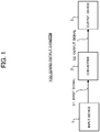
- FIG. 1 shows a configuration of a sound output system 100 according to the present embodiment.
- the sound output system 100 is a system for reproducing sound data by upconverting sound data of the CD standard to that of the high-resolution standard, and as shown in FIG. 1 , the sound output system 100 includes an input device 1, a converter 2, and an output device 3.
- the input device 1 inputs an input signal S1, which is digital data of a CD sound source, into the converter 2.
- the input device 1 may, for example, be an interface device that reads sound data from a recording medium such as a CD, be a communication device that receives sound data transmitted from another device by wire or wirelessly, or be a storage device that stores the input signal S1.
- the converter 2 upconverts the input signal S1 input from the input device 1 to output an output signal S2, which is digital data of the high-resolution standard, to the output device 3.
- the converter 2 first upconverts each of a sampling frequency and a bit length to a predetermined high-resolution format.
- the signal is one with the quality of the CD specification due to being a signal containing quantization noise and not yet subjected to high-frequency interpolation.
- processing for attenuating the quantization noise contained in the input signal S1 quantization noise attenuation processing
- overtone generation processing are performed to generate the output signal S2 that is sound data with quality exceeding the CD specification.
- the converter 2 is an example of a "signal processing device" in the present invention.
- the output device 3 is, for example, a speaker or the like and outputs sound based on the output signal S2 output from the converter 2. It is noted that at least one of the input device 1 and the output device 3 may be configured integrally with the converter 2. The input device 1 and the output device 3 may be configured integrally.
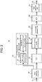
- FIG. 2 shows a functional block configuration diagram of the converter 2.
- the converter 2 includes a hardware configuration such as a central processing unit (CPU), a read-only memory (ROM), a random-access memory (RAM), and functionally includes a time window cut-out block 21, a fast Fourier transform (FFT) block 22, an attenuation amount limitation block 23, a quantization noise attenuation block 24, an overtone generation block 25, an inverse fast Fourier transform (IFFT) block 26, and a time window resynthesis block 27.
- CPU central processing unit
- ROM read-only memory
- RAM random-access memory
- FFT fast Fourier transform
- IFFT inverse fast Fourier transform
- the time window cut-out block 21 Based on any one of various window functions such as a hanning window, the time window cut-out block 21 cuts out the time waveform of the sound data from the input signal S1 for each window width with a predetermined time length (for each frame) while applying the window function with overlap. Then, the time window cut-out block 21 supplies sound data for each frame to each of the FFT block 22 and the attenuation amount limitation block 23.
- window functions such as a hanning window
- the FFT block 22 performs fast Fourier transform on the sound data with the predetermined time length, outputted by the time window cut-out block 21, and outputs amplitude and a phase for each frequency.
- information on the amplitude is supplied to the quantization noise attenuation block 24, and information on the phase is supplied to the overtone generation block 25.
- the attenuation amount limitation block 23 determines the maximum attenuation amount with respect to the amplitude in a frequency domain to be attenuated in the quantization noise attenuation block 24, based on the magnitude of the signal level of sound data supplied from the time window cut-out block 21.
- the attenuation amount limitation block 23 has an RMS value calculation block 31 and a maximum attenuation amount calculation block 32.
- the RMS value calculation block 31 calculates a root mean square (RMS) value for each frame of the sound data supplied from the time window cut-out block 21. In this case, the RMS value calculated by the RMS value calculation block 31 corresponds to the magnitude of an average signal level of the sound data for each frame.
- RMS root mean square
- the maximum attenuation amount calculation block 32 calculates the maximum attenuation amount corresponding to the upper limit of the attenuation amount, which is used in the quantization noise attenuation block 24, for the amplitude in the frequency domain. A detail of the calculation method for the maximum attenuation amount will be described later with reference to FIG. 3A .
- the RMS value calculation block 31 may calculate a calculated value other than the RMS value so long as being the value indicating the signal level of the sound data.
- the quantization noise attenuation block 24 adjusts the amplitude in the frequency domain of a target frame based on the maximum attenuation amount determined by the attenuation amount limitation block 23, to thereby attenuate the quantization noise.
- the quantization noise attenuation block 24 estimates level less than -90.3 dB, which is the minimum level reproducible in the CD standard, as one generated due to quantization noise, and therefore attenuates the signal level at the frequency whose level is less than - 90.3 dB.
- the quantization noise attenuation block 24 adjusts the signal level at the frequency whose level is less than -90.3 dB so as not to exceed the maximum attenuation amount determined by the attenuation amount limitation block 23.
- -90.3 dB is an example of a "predetermined level” in the present invention.
- the frequency whose level is less than -90.3 dB is an example of a "predetermined frequency band" in the present invention.
- the overtone generation block 25 On the basis of the information indicative of the amplitude for each frequency outputted by the quantization noise attenuation block 24, and the information indicative of the phase outputted by the FFT block 22, the overtone generation block 25 performs the overtone generation processing to generate an overtone for high-frequency interpolation. Thereby, the overtone generation block 25 performs pseudo up-sampling on the CD sound source. Any known overtone generation technique may be applied to the overtone generation processing.
- the IFFT block 26 performs inverse fast Fourier transform on the sound data in the frequency domain subjected to the overtone generation processing, to convert the sound data for each frame from the frequency domain to a time domain.
- the time window resynthesis block 27 overlaps and adds the sound data of each frame outputted by the IFFT block 26 to generate the smoothly connected output signal S2. Then, the time window resynthesis block 27 supplies the generated output signal S2 to the output device 3.
- the time window cut-out block 21 is an example of an "acquisition unit” in the present invention
- the FFT block 22 is an example of a “conversion unit” in the present invention
- the attenuation amount limitation block 23 and the quantization noise attenuation block 24 are an example of a "quantization noise control unit” in the present invention
- the overtone generation block 25 is an example of an “overtone generation unit” in the present invention
- the time window resynthesis block 27 is an example of an "output unit” in the present invention.
- the CPU and the like of the converter 2 which constitute each block are an example of a "computer” for executing a program in the present invention.
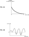
- FIG. 3A is a graph schematically showing the relationship between the dB value converted from the RMS value calculated by the RMS value calculation block 31 and the maximum attenuation amount determined by the maximum attenuation amount calculation block 32.
- the maximum attenuation amount is defined in the level range from 0 dB to about -90 dB. It is noted that about -90 dB corresponds to the minimum value of the level reproducible in the CD standard.
- the maximum attenuation amount calculation block 32 increases the maximum attenuation amount as the level approaches -90 dB, that is, as the level gets smaller.
- the maximum attenuation amount calculation block 32 determines the maximum attenuation amount from the RMS value calculated by the RMS value calculation block 31 or the dB value converted from the RMS value.
- the relation between the maximum attenuation amount and the level is not limited to the relation represented by the graph shown in FIG. 3A and that it may only be necessary to satisfy a relation in which the maximum attenuation amount increases with decreasing level.
- the relation may be a relation indicated by a linear graph.
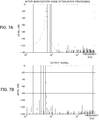
- FIG. 3B shows a frequency characteristic of the sound data cut out by the time window cut-out block 21.
- a solid line indicates a characteristic before the quantization noise attenuation processing
- a dashed line indicates a characteristic after the quantization noise attenuation processing by quantization noise attenuation block 24.
- the quantization noise attenuation block 24 attenuates the signal level at the frequency whose level is less than -90.3 dB, which is the minimum level reproducible in the CD standard, so as not to exceed the maximum attenuation amount determined by the attenuation amount limitation block 23.
- the quantization noise attenuation block 24 calculates the difference between -90.3 dB and the signal level of the characteristic as the attenuation amount. Then, when the calculated attenuation amount exceeds the maximum attenuation amount, the quantization noise attenuation block 24 takes the maximum attenuation amount as the attenuation amount to be applied. Thereby, the quantization noise attenuation block 24 can suitably attenuate the quantization noise while preventing the characteristic from being discontinuous.
- FIG. 4A shows a signal waveform obtained by quantizing sound data of a sine wave in accordance with the high-resolution standard (24-bit quantization)
- FIG. 4B shows a signal waveform obtained by quantizing sound data of a sine wave in accordance with the CD standard (16-bit quantization).
- FIG. 4C shows the frequency characteristic of the sound data in FIG. 4A
- FIG. 4D shows the frequency characteristic of the sound data in FIG. 4B .
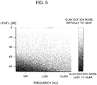
- FIG. 5 is a graph quantitatively representing the sense of hearing for quantization noise generated in the CD standard when the combination of the frequency and the level of the original sound data, which is a sine wave, is changed.
- quantization noise generated with respect to each of any combinations of the frequency and level of the original sound data that is a sine wave, is calculated and multiplied by the hearing-sense characteristic derived from a loudness curve or the like, to quantitatively obtain and visualize the sense of hearing for the quantization noise.
- FIG. 5 shows that the darker the color of the region, the easier the quantization noise is to hear (i.e., the easier the difference between the high-resolution standard and the CD standard is to perceive) in the region. It is noted that the applicant has conducted a listening experiment to obtain the same result as the tendency of the graph of FIG. 5 .
- the quantization noise is easy to hear. It is thus estimated that in the case of the CD standard, in the low-level region and the low-frequency band, the sound quality has been degraded due to the quantization noise. It is conceivable therefrom that the lower the input level of the input signal S1 is, or the lower the frequency of the input signal S1 is, the higher the need to attenuate the quantization noise becomes. Furthermore, it is conceivable that the lower the input level of the input signal S1 and the frequency of the input signal S1, the higher the need to attenuate the quantization noise.
- FIG. 6A shows the frequency characteristic of the input signal S1 with a relatively large input level
- FIG. 6B shows a characteristic after the Fourier transform has been performed by applying a window function to the input signal S1 that has the frequency characteristic shown in FIG. 6A (i.e., before the quantization noise attenuation processing).
- FIG. 7A shows a characteristic after the quantization noise attenuation processing has been performed to uniformly attenuate the frequency less than -90.3 dB with respect to the characteristic of FIG. 6B
- FIG. 7B shows the frequency characteristic of the output signal S2, generated from the characteristic shown in FIG. 7A .
- the range of the characteristic portion to be the peak spreads when the input level of the input signal S1 is relatively large, by applying the window function, the range of the characteristic portion to be the peak spreads. Then, as shown in FIG. 7A , when the quantization noise attenuation processing is performed to uniformly attenuate the frequency less than -90.3 dB without depending on the input level of the input signal S1, the spread portion described above also attenuates with the quantization noise.
- the spread portion is originally required information to correctly turn the main signal contained in the input signal, except for the quantization noise, back to the output signal S2 in the IFFT block 26 and the time window resynthesis block 27.
- noise caused by the attenuation of the spread portion described above is generated in the output signal S2.
- FIG. 8A shows the frequency characteristic of the input signal S1 with a relatively small input level
- FIG. 8B shows a characteristic after the Fourier transform has been performed by applying a window function to the input signal S1 that has the frequency characteristic shown in FIG. 8A (i.e., before the quantization noise attenuation processing).
- FIG. 9A shows a characteristic after the quantization noise attenuation processing has been performed to uniformly attenuate the frequency less than -90.3 dB with respect to the characteristic of FIG. 8B
- FIG. 9B shows the frequency characteristic of the output signal S2, generated from the characteristic shown in FIG. 9A .
- the quantization noise attenuation processing is performed when the input level of the input signal S1 is relatively small, it is possible to suitably attenuate the quantization noise without attenuating the originally required input signal.
- the smaller the input level of the input signal S1 is the easier the quantization noise is to hear, and thus the higher the need to attenuate the quantization noise becomes.
- the smaller the input level of the input signal S1 is the larger the maximum attenuation amount which the converter 2 sets becomes. Thereby, the converter 2 can effectively attenuate the quantization noise while suitably reducing the attenuation of the originally required input signal.
- the time window cut-out block 21 of the converter 2 acquires the input signal S1 that is the quantized sound data, and cuts out sound data for each predetermined time interval. Then, the attenuation amount limitation block 23 determines the maximum attenuation amount based on the level of the sound data for each cut-out frame. Thereafter, on the basis of the maximum attenuation amount determined by the attenuation amount limitation block 23, the quantization noise attenuation block 24 determines the attenuation amount for the amplitude in the frequency domain of the input signal S1 (i.e. the control amount for the quantization noise). Thereby, the converter 2 can effectively attenuate the quantization noise in an audible range while suitably reducing the attenuation of the originally required input signal .
- the maximum attenuation amount calculation block 32 has determined the maximum attenuation amount with respect to each frame based on the RMS value corresponding to the average input level for each frame. As another example, the maximum attenuation amount calculation block 32 may determine the maximum attenuation amount for each frame by further considering the frequency for each frame in addition to the RMS value described above.
- FIG. 10 shows the block configuration of the converter 2 according to the present modification.
- the attenuation amount limitation block 23 of the converter 2 has a frequency gravity-center calculation block 33 in addition to the RMS value calculation block 31 and the maximum attenuation amount calculation block 32.
- the frequency gravity-center calculation block 33 calculates the center of gravity of the frequency (i.e. spectral center of gravity) based on the frequency spectrum obtained by the FFT block 22 which performs the Fourier transform on the input signal S1 cut out for each frame by the time window cut-out block 21. Then, the frequency gravity-center calculation block 33 supplies the information on the calculated spectral center of gravity to the maximum attenuation amount calculation block 32.
- the maximum attenuation amount calculation block 32 determines the maximum attenuation amount based on the RMS value obtained from the RMS value calculation block 31 and the spectral center of gravity obtained from the frequency gravity-center calculation block 33. In this case, for example, with reference to a table or a formula stored in the memory of the converter 2 in advance, the maximum attenuation amount calculation block 32 sets the maximum attenuation amount to be higher with the RMS value being lower, and the maximum attenuation amount calculation block 32 sets the maximum attenuation amount to be higher with the spectral center of gravity of the frequency being lower.
- the center of the spectrum has been calculated for each frame. Instead, the center of the spectrum may be calculated at intervals of a predetermined time length or, for example, the center of gravity corresponding to one song may be calculated as the center of the spectrum.
- the converter 2 may convert the input signal S1 of the sound source such as MPEG-1 Audio Layer-3 (MP3) to the output signal S2 having a specification of the CD standard or the high-resolution standard level.
- MP3 MPEG-1 Audio Layer-3
- the converter 2 after decoding the input signal S1, the converter 2 performs the processing of each processing block shown in FIG. 2 and the like, thereby performing the attenuation of quantization noise, the overtone generation, and the like.
- the quantization noise attenuation block 24 of the converter 2 estimates, as a component generated due to the quantization noise, a component with level less than the minimum level reproducible in the standard employed to the input signal S1 (-90.3 dB in the embodiment).
- the converter 2 attenuates the signal level at the frequency whose level is equal to or less than the above minimum level.
- the present invention is suitably applied to various processing for up-conversion to a standard with a higher number of quantization bits.
- the example of the setting the level configured to determine the quantization noise to - 90.3 dB has been shown, but the example to which the present invention is applicable is not limited thereto, and the level configured to determine the quantization noise may be adjusted in accordance with the conditions of the time window and frequency conversion.
- the example has been shown in the description of the attenuation amount limitation block 23 of FIG. 2 where the maximum attenuation amount with respect to the amplitude in the frequency domain, attenuated in the quantization noise attenuation block 24, is determined based on the magnitude of the signal levels in all the frequency bands of the sound data supplied from the time window cut-out block 21.
- the determination method for the maximum attenuation amount is not limited thereto.
- the maximum attenuation amount calculation block 32 divides the sound data supplied from the time window cut-out block 21 into a band larger than a certain frequency and a band equal to or less than the frequency, and from the RMS value or the dB value converted from the RMS value in each band, the maximum attenuation amount calculation block 32 determines the maximum attenuation amount to be applied in each of the divided band.
- the frequency band is divided into a frequency band surrounded by a dashed line 41 and a frequency band not surrounded thereby.
- the frequency band is divided into a band larger than 2000 Hz and a band of 2000 Hz or less.
- the RMS value in the band larger than 2000 Hz is smaller than the RMS value in the band of 2000 Hz or less. Therefore, the maximum attenuation amount in the band larger than 2000 Hz is larger than the maximum attenuation amount in the band of 2000 Hz or less.
- the frequency band has been divided into two relative to 2000 Hz, but the present invention is not limited thereto.
- the frequency band may be divided into three (a frequency band surrounded by a dashed line 42, a frequency band surrounded by a single-dot chain line 43, and the other frequency band) relative to 1000 Hz and 10000 Hz, or may be divided into three or more bands.
- the value to be the reference for dividing the frequency band and the number of bands after the division can be changed as appropriate.
- the maximum attenuation amount calculation block 32 determines the maximum attenuation amount to be applied in each of the divided bands, from the RMS value or the dB value converted from the RMS value in each of the divided bands.
Landscapes
- Engineering & Computer Science (AREA)
- Physics & Mathematics (AREA)
- Acoustics & Sound (AREA)
- Signal Processing (AREA)
- Audiology, Speech & Language Pathology (AREA)
- Health & Medical Sciences (AREA)
- Computational Linguistics (AREA)
- Human Computer Interaction (AREA)
- Multimedia (AREA)
- Spectroscopy & Molecular Physics (AREA)
- Theoretical Computer Science (AREA)
- Quality & Reliability (AREA)
- Compression, Expansion, Code Conversion, And Decoders (AREA)
- Analogue/Digital Conversion (AREA)
Abstract
Description
- The present invention relates to a technique for controlling quantization noise.
- Conventionally, there is known a technique for removing quantization noise of data digitized by use of a low number of quantization bits. For example,
Patent Reference 1 discloses a technique in which digital data quantized by use of a low number of bits is subjected to spectrum conversion to omit a spectrum at or below a predetermined level, and then the data to which inverse Fourier transform is applied is outputted. -
Patent Reference 1
Japanese Patent Laid-Open No.7-193502 - In
Patent Reference 1, there has been a problem where, due to uniform removal of quantization noise that is not annoying in the sense of hearing, an originally existing sound component is also removed together with the quantization noise. - Examples of problems to be solved by the present invention include the example as described above. A main object of the present invention is to provide a signal processing device capable of suitably attenuating quantization noise.
- An invention recited in a claim is a signal processing device including: an acquisition unit configured to acquire sound data subjected to quantization; and a quantization noise control unit configured to determine a control amount for quantization noise of the sound data, generated due to the quantization, based on the level of the sound data.
- An invention recited in a claim is a control method to be performed by a signal processing device, the method including: an acquisition step of acquiring sound data subjected to quantization; and a quantization noise control step of determining a control amount for quantization noise of the sound data, generated due to the quantization, based on the level of the sound data.
- An invention recited in a claim is a program to be executed by a computer, the program causing the computer to function as an acquisition unit configured to acquire sound data subjected to quantization, and a quantization noise control unit configured to determine a control amount for quantization noise of the sound data, generated due to the quantization, based on the level of the sound data.
-
-
FIG. 1 shows a configuration of a sound output system according to an embodiment. -
FIG. 2 shows a functional block configuration diagram of a converter. -
FIGS. 3A and 3B show graphs defining the maximum attenuation amount, and show a specific example of attenuation processing in a frequency domain. -
FIGS. 4A to 4D show signal waveforms in a time domain and frequency characteristics when a sine wave signal is quantized in accordance with each of the high-resolution standard and compact disc (CD) standard. -
FIG. 5 shows a graph quantitatively representing the sense of hearing for quantization noise generated in the CD standard. -
FIG. 6A is a frequency characteristic of an input signal with a relatively large input level, andFIG. 6B is a frequency characteristic showing a calculation result of Fourier transform performed by applying a window function to the input signal with the frequency characteristic of 6A. -
FIG. 7A shows a frequency characteristic obtained by performing quantization noise attenuation processing on the frequency characteristic ofFIG. 6B , andFIG. 7B shows the frequency characteristic of the output signal. -
FIG. 8A is a frequency characteristic of an input signal with a relatively small input level, andFIG. 8B is a frequency characteristic showing a calculation result of Fourier transform performed by applying a window function to the input signal with the frequency characteristic of 8A. -
FIG. 9A shows a frequency characteristic obtained by performing the quantization noise attenuation processing on the frequency characteristic ofFIG. 8B , andFIG. 9B shows the frequency characteristic of the output signal. -
FIG. 10 shows a block configuration diagram of a converter according to a modification. -
FIGS. 11A and 11B are diagrams each showing an example of division of frequency bands in a case where the maximum attenuation amount is determined with respect to each of a plurality of frequency bands. - In a preferred embodiment of the present invention, a signal processing device includes: an acquisition unit configured to acquire sound data subjected to quantization; and a quantization noise control unit configured to determine a control amount for quantization noise of the sound data, generated due to the quantization, based on the level of the sound data. In this embodiment, focusing on the fact that the sense of hearing for quantization noise varies in accordance with the level of the acquired sound data, the signal processing device determines the control amount for controlling the quantization noise based on the level of the sound data. Thereby, the signal processing device can suitably control quantization noise heard by a user to reduce its influence.
- In one aspect of the signal processing device, the control amount is an attenuation amount by which a signal level of the sound data is attenuated in a predetermined frequency band, and the quantization noise control unit changes the attenuation amount based on the sound level. With this aspect, the quantization noise control unit can suitably prevent unnecessary removal of an originally existing sound component while attenuating the quantization noise.
- In another aspect of the signal processing device, the smaller the sound level is, the larger the quantization noise control unit makes the attenuation amount. As described later in an embodiment, the applicant has obtained knowledge that the smaller the sound level of the sound data is, the easier the quantization noise is to hear and that the smaller the sound level of the sound data is, the smaller the influence, caused by quantization noise attenuation processing, on a sound component that is not noise becomes. Thus, with this aspect, the signal processing device can suitably attenuate the quantization noise while avoiding the influence on the originally existing sound component.
- In another aspect of the signal processing device, the quantization noise control unit determines the attenuation amount based on the sound level and a frequency of the sound data. As described later in the embodiment, the applicant has obtained knowledge that the quantization noise tends to be easy to hear when the frequency of the input signal is relatively low. Thus, with this aspect, the signal processing device can more effectively attenuate the quantization noise while avoiding the influence on the originally existing sound component. Preferably, the lower the frequency is, the larger the quantization noise control unit may make the attenuation amount.
- Another aspect of the signal processing device further includes a conversion unit configured to convert a time waveform of the sound data to a frequency domain, and the quantization noise control unit attenuates amplitude which is less than a predetermined level, based on the control amount. With this aspect, the signal processing device can attenuate the amplitude affected by the quantization noise and suitably reduce the quantization noise.
- In another aspect of the signal processing device, the conversion unit converts the time waveform of the sound data, cut out with a predetermined time interval, to a frequency domain. When the sound data is cut out in this way, characteristic in the frequency domain spreads due to the influence of the cut-out, and depending on the level of the sound data, the quantization noise is mixed with the original sound component in a specific frequency band. Even in this case, by determining the control amount based on the sound level, the signal processing device can suitably reduce the influence on the originally existing sound component while suitably attenuating the quantization noise in the range to be heard by the user.
- Another aspect of the signal processing device further includes a division unit configured to divide the sound data into a plurality of frequency bands, and the quantization noise control unit determines the control amount for the quantization noise with respect to each of the plurality of frequency bands. Thereby, the signal processing device can appropriately determine the control amount with respect to each frequency band. In a preferred example, the signal processing device further includes an overtone generation unit configured to perform overtone generation on the sound data with the quantization noise controlled, and an output unit configured to output the sound data subjected to the overtone generation. With this aspect, the signal processing device can suitably perform up-conversion to a greater standard with higher quality.
- In another embodiment of the present invention, a control method to be performed by a signal processing device includes: an acquisition step of acquiring sound data subjected to quantization; and a quantization noise control step of determining a control amount for quantization noise of the sound data, generated due to the quantization, based on the level of the sound data. By performing this control method, the signal processing device can suitably control quantization noise heard by the user to reduce its influence.
- In another embodiment of the present invention, a program to be executed by a computer causes the computer to function as acquisition unit configured to acquire sound data subjected to quantization, and quantization noise control unit configured to determine a control amount for quantization noise of the sound data, generated due to the quantization, based on the level of the sound data. By executing this program, the computer can suitably control quantization noise heard by the user to reduce its influence. Preferably, the program is stored in a storage medium.
- A preferred embodiment of the present invention will be described below with reference to the drawings.
Hereinafter, "high-resolution" means a sound source with a sampling frequency of 96 kHz and a bit length of 24 bit, or higher precision. -
FIG. 1 shows a configuration of asound output system 100 according to the present embodiment. Thesound output system 100 is a system for reproducing sound data by upconverting sound data of the CD standard to that of the high-resolution standard, and as shown inFIG. 1 , thesound output system 100 includes aninput device 1, aconverter 2, and anoutput device 3. - The
input device 1 inputs an input signal S1, which is digital data of a CD sound source, into theconverter 2. Theinput device 1 may, for example, be an interface device that reads sound data from a recording medium such as a CD, be a communication device that receives sound data transmitted from another device by wire or wirelessly, or be a storage device that stores the input signal S1. - The
converter 2 upconverts the input signal S1 input from theinput device 1 to output an output signal S2, which is digital data of the high-resolution standard, to theoutput device 3. In this case, as described later, theconverter 2 first upconverts each of a sampling frequency and a bit length to a predetermined high-resolution format. At this time, although the format has been upconverted, the signal is one with the quality of the CD specification due to being a signal containing quantization noise and not yet subjected to high-frequency interpolation. Next, processing for attenuating the quantization noise contained in the input signal S1 (quantization noise attenuation processing) and overtone generation processing are performed to generate the output signal S2 that is sound data with quality exceeding the CD specification. Theconverter 2 is an example of a "signal processing device" in the present invention. - The
output device 3 is, for example, a speaker or the like and outputs sound based on the output signal S2 output from theconverter 2. It is noted that at least one of theinput device 1 and theoutput device 3 may be configured integrally with theconverter 2. Theinput device 1 and theoutput device 3 may be configured integrally. -
FIG. 2 shows a functional block configuration diagram of theconverter 2. Theconverter 2 includes a hardware configuration such as a central processing unit (CPU), a read-only memory (ROM), a random-access memory (RAM), and functionally includes a time window cut-out block 21, a fast Fourier transform (FFT)block 22, an attenuationamount limitation block 23, a quantizationnoise attenuation block 24, anovertone generation block 25, an inverse fast Fourier transform (IFFT)block 26, and a timewindow resynthesis block 27. - Based on any one of various window functions such as a hanning window, the time window cut-
out block 21 cuts out the time waveform of the sound data from the input signal S1 for each window width with a predetermined time length (for each frame) while applying the window function with overlap. Then, the time window cut-out block 21 supplies sound data for each frame to each of theFFT block 22 and the attenuationamount limitation block 23. - The
FFT block 22 performs fast Fourier transform on the sound data with the predetermined time length, outputted by the time window cut-out block 21, and outputs amplitude and a phase for each frequency. In this case, information on the amplitude is supplied to the quantizationnoise attenuation block 24, and information on the phase is supplied to theovertone generation block 25. - The attenuation
amount limitation block 23 determines the maximum attenuation amount with respect to the amplitude in a frequency domain to be attenuated in the quantizationnoise attenuation block 24, based on the magnitude of the signal level of sound data supplied from the time window cut-out block 21. The attenuationamount limitation block 23 has an RMSvalue calculation block 31 and a maximum attenuationamount calculation block 32. The RMSvalue calculation block 31 calculates a root mean square (RMS) value for each frame of the sound data supplied from the time window cut-out block 21. In this case, the RMS value calculated by the RMSvalue calculation block 31 corresponds to the magnitude of an average signal level of the sound data for each frame. Based on the RMS value calculated by the RMSvalue calculation block 31, the maximum attenuationamount calculation block 32 calculates the maximum attenuation amount corresponding to the upper limit of the attenuation amount, which is used in the quantizationnoise attenuation block 24, for the amplitude in the frequency domain. A detail of the calculation method for the maximum attenuation amount will be described later with reference toFIG. 3A . - It is noted that the RMS
value calculation block 31 may calculate a calculated value other than the RMS value so long as being the value indicating the signal level of the sound data. - The quantization
noise attenuation block 24 adjusts the amplitude in the frequency domain of a target frame based on the maximum attenuation amount determined by the attenuationamount limitation block 23, to thereby attenuate the quantization noise. In the present embodiment, the quantizationnoise attenuation block 24 estimates level less than -90.3 dB, which is the minimum level reproducible in the CD standard, as one generated due to quantization noise, and therefore attenuates the signal level at the frequency whose level is less than - 90.3 dB. At this time, the quantizationnoise attenuation block 24 adjusts the signal level at the frequency whose level is less than -90.3 dB so as not to exceed the maximum attenuation amount determined by the attenuationamount limitation block 23. A specific example of the adjustment processing will be described later with reference toFIG. 3B . It is noted that -90.3 dB is an example of a "predetermined level" in the present invention. Further, the frequency whose level is less than -90.3 dB is an example of a "predetermined frequency band" in the present invention. - On the basis of the information indicative of the amplitude for each frequency outputted by the quantization
noise attenuation block 24, and the information indicative of the phase outputted by theFFT block 22, theovertone generation block 25 performs the overtone generation processing to generate an overtone for high-frequency interpolation. Thereby, theovertone generation block 25 performs pseudo up-sampling on the CD sound source. Any known overtone generation technique may be applied to the overtone generation processing. - The
IFFT block 26 performs inverse fast Fourier transform on the sound data in the frequency domain subjected to the overtone generation processing, to convert the sound data for each frame from the frequency domain to a time domain. The timewindow resynthesis block 27 overlaps and adds the sound data of each frame outputted by theIFFT block 26 to generate the smoothly connected output signal S2. Then, the timewindow resynthesis block 27 supplies the generated output signal S2 to theoutput device 3. - In the configuration shown in
FIG. 2 , the time window cut-out block 21 is an example of an "acquisition unit" in the present invention, and theFFT block 22 is an example of a "conversion unit" in the present invention. Further, the attenuationamount limitation block 23 and the quantizationnoise attenuation block 24 are an example of a "quantization noise control unit" in the present invention, theovertone generation block 25 is an example of an "overtone generation unit" in the present invention, and the timewindow resynthesis block 27 is an example of an "output unit" in the present invention. Further, the CPU and the like of theconverter 2 which constitute each block are an example of a "computer" for executing a program in the present invention. - Here, a specific description will be given of a method for setting of the maximum attenuation amount by the maximum attenuation
amount calculation block 32. -
FIG. 3A is a graph schematically showing the relationship between the dB value converted from the RMS value calculated by the RMSvalue calculation block 31 and the maximum attenuation amount determined by the maximum attenuationamount calculation block 32. In the example ofFIG. 3A , the maximum attenuation amount is defined in the level range from 0 dB to about -90 dB. It is noted that about -90 dB corresponds to the minimum value of the level reproducible in the CD standard. - As shown in
FIG. 3A , the maximum attenuationamount calculation block 32 increases the maximum attenuation amount as the level approaches -90 dB, that is, as the level gets smaller. In this case, for example, with reference to a formula, a table, or the like corresponding toFIG. 3A stored in advance, the maximum attenuationamount calculation block 32 determines the maximum attenuation amount from the RMS value calculated by the RMSvalue calculation block 31 or the dB value converted from the RMS value. Thereby, the smaller the input level of the input signal S1 is, the larger the attenuation amount can be made, and the quantization noise can be attenuated effectively while suitably reducing the attenuation of the originally required input signal. This effect will be described in more detail in the [Effect] section. - It is noted that the relation between the maximum attenuation amount and the level is not limited to the relation represented by the graph shown in
FIG. 3A and that it may only be necessary to satisfy a relation in which the maximum attenuation amount increases with decreasing level. For example, the relation may be a relation indicated by a linear graph. - Next, a specific example of the quantization noise attenuation processing by the quantization
noise attenuation block 24 will be described. -
FIG. 3B shows a frequency characteristic of the sound data cut out by the time window cut-out block 21. InFIG. 3B , a solid line indicates a characteristic before the quantization noise attenuation processing , and a dashed line indicates a characteristic after the quantization noise attenuation processing by quantizationnoise attenuation block 24. - As shown in
FIG. 3B , the quantizationnoise attenuation block 24 attenuates the signal level at the frequency whose level is less than -90.3 dB, which is the minimum level reproducible in the CD standard, so as not to exceed the maximum attenuation amount determined by the attenuationamount limitation block 23. Here, as an example, in a target frequency band, the quantizationnoise attenuation block 24 calculates the difference between -90.3 dB and the signal level of the characteristic as the attenuation amount. Then, when the calculated attenuation amount exceeds the maximum attenuation amount, the quantizationnoise attenuation block 24 takes the maximum attenuation amount as the attenuation amount to be applied. Thereby, the quantizationnoise attenuation block 24 can suitably attenuate the quantization noise while preventing the characteristic from being discontinuous. - Next, the effect of the present embodiment will be supplemented with reference to
FIGS. 4A to 9B . -
FIG. 4A shows a signal waveform obtained by quantizing sound data of a sine wave in accordance with the high-resolution standard (24-bit quantization), andFIG. 4B shows a signal waveform obtained by quantizing sound data of a sine wave in accordance with the CD standard (16-bit quantization). Further,FIG. 4C shows the frequency characteristic of the sound data inFIG. 4A, and FIG. 4D shows the frequency characteristic of the sound data inFIG. 4B . - As shown in
FIG. 4B , in the case of the CD standard, small level sound or the like has become a stepped signal. Thus, as shown inFIG. 4D , in the case of the CD standard, even in an audible frequency band of 20 kHz or less, quantization noise, which hardly appears in the quantization in the high-resolution standard (24 bits here), is generated in large amount. On the other hand, in the case of the high-resolution standard, a smooth signal waveform has been formed due to the number of quantization bits being high (cf.FIG. 4A ), and the quantization noise has hardly been generated (cf.FIG. 4C ) . -
FIG. 5 is a graph quantitatively representing the sense of hearing for quantization noise generated in the CD standard when the combination of the frequency and the level of the original sound data, which is a sine wave, is changed. InFIG. 5 , quantization noise, generated with respect to each of any combinations of the frequency and level of the original sound data that is a sine wave, is calculated and multiplied by the hearing-sense characteristic derived from a loudness curve or the like, to quantitatively obtain and visualize the sense of hearing for the quantization noise.FIG. 5 shows that the darker the color of the region, the easier the quantization noise is to hear (i.e., the easier the difference between the high-resolution standard and the CD standard is to perceive) in the region. It is noted that the applicant has conducted a listening experiment to obtain the same result as the tendency of the graph ofFIG. 5 . - According to the graph of
FIG. 5 , it is understood that there is a tendency that the lower the level and frequency of the input signal are, the easier the quantization noise is to hear, and particularly in a level region of about -70 dB or less as well as in a low-frequency band of about 1 kHz or less, the quantization noise is easy to hear. It is thus estimated that in the case of the CD standard, in the low-level region and the low-frequency band, the sound quality has been degraded due to the quantization noise. It is conceivable therefrom that the lower the input level of the input signal S1 is, or the lower the frequency of the input signal S1 is, the higher the need to attenuate the quantization noise becomes. Furthermore, it is conceivable that the lower the input level of the input signal S1 and the frequency of the input signal S1, the higher the need to attenuate the quantization noise. - Here, a description will be given of the influence at the time when in the quantization noise attenuation processing, the maximum attenuation amount is not provided and the amplitude is uniformly attenuated regardless of the magnitude of the input level of the input signal S1.
-
FIG. 6A shows the frequency characteristic of the input signal S1 with a relatively large input level, andFIG. 6B shows a characteristic after the Fourier transform has been performed by applying a window function to the input signal S1 that has the frequency characteristic shown inFIG. 6A (i.e., before the quantization noise attenuation processing). Further,FIG. 7A shows a characteristic after the quantization noise attenuation processing has been performed to uniformly attenuate the frequency less than -90.3 dB with respect to the characteristic ofFIG. 6B , andFIG. 7B shows the frequency characteristic of the output signal S2, generated from the characteristic shown inFIG. 7A . - As shown in
FIGS. 6A and 6B , when the input level of the input signal S1 is relatively large, by applying the window function, the range of the characteristic portion to be the peak spreads. Then, as shown inFIG. 7A , when the quantization noise attenuation processing is performed to uniformly attenuate the frequency less than -90.3 dB without depending on the input level of the input signal S1, the spread portion described above also attenuates with the quantization noise. The spread portion is originally required information to correctly turn the main signal contained in the input signal, except for the quantization noise, back to the output signal S2 in theIFFT block 26 and the timewindow resynthesis block 27. Hence, as shown inFIG. 7B , noise caused by the attenuation of the spread portion described above is generated in the output signal S2. - As thus described, in the case where the quantization noise attenuation processing is performed without providing the maximum attenuation amount when the input level of the input signal S1 is relatively large, there is a possibility that the originally required signal also attenuates due to the quantization noise attenuation processing, resulting in the degradation of the sound quality.
-
FIG. 8A shows the frequency characteristic of the input signal S1 with a relatively small input level, andFIG. 8B shows a characteristic after the Fourier transform has been performed by applying a window function to the input signal S1 that has the frequency characteristic shown inFIG. 8A (i.e., before the quantization noise attenuation processing). Further,FIG. 9A shows a characteristic after the quantization noise attenuation processing has been performed to uniformly attenuate the frequency less than -90.3 dB with respect to the characteristic ofFIG. 8B , andFIG. 9B shows the frequency characteristic of the output signal S2, generated from the characteristic shown inFIG. 9A . - As shown in
FIGS. 8A and 8B , when the input level of the input signal S1 is relatively small, even in a case where the Fourier transform is performed by applying a window function, the range of the characteristic portion to be the peak does not spread to the low-level region. Therefore, in this case, as shown inFIG. 9A , even when the quantization noise attenuation processing for attenuating the frequency less than -90.3 dB is performed, the attenuation range of the spread portion described above is small. Thus, in this case, as shown inFIG. 9B , noise caused by the quantization noise attenuation processing is hardly generated in the output signal S2. - As thus described, in the case where the quantization noise attenuation processing is performed when the input level of the input signal S1 is relatively small, it is possible to suitably attenuate the quantization noise without attenuating the originally required input signal. Further, as described with reference to
FIG. 5 , the smaller the input level of the input signal S1 is, the easier the quantization noise is to hear, and thus the higher the need to attenuate the quantization noise becomes. Considering the above, in the present embodiment, the smaller the input level of the input signal S1 is, the larger the maximum attenuation amount which theconverter 2 sets becomes. Thereby, theconverter 2 can effectively attenuate the quantization noise while suitably reducing the attenuation of the originally required input signal. - As described above, the time window cut-
out block 21 of theconverter 2 acquires the input signal S1 that is the quantized sound data, and cuts out sound data for each predetermined time interval. Then, the attenuationamount limitation block 23 determines the maximum attenuation amount based on the level of the sound data for each cut-out frame. Thereafter, on the basis of the maximum attenuation amount determined by the attenuationamount limitation block 23, the quantizationnoise attenuation block 24 determines the attenuation amount for the amplitude in the frequency domain of the input signal S1 (i.e. the control amount for the quantization noise). Thereby, theconverter 2 can effectively attenuate the quantization noise in an audible range while suitably reducing the attenuation of the originally required input signal . - Next, modifications preferred for the present embodiment will be described. The following modifications may be applied to the above embodiment in any combination.
- In the above embodiment, as an example, the maximum attenuation
amount calculation block 32 has determined the maximum attenuation amount with respect to each frame based on the RMS value corresponding to the average input level for each frame. As another example, the maximum attenuationamount calculation block 32 may determine the maximum attenuation amount for each frame by further considering the frequency for each frame in addition to the RMS value described above. -
FIG. 10 shows the block configuration of theconverter 2 according to the present modification. As shown inFIG. 10 , the attenuationamount limitation block 23 of theconverter 2 has a frequency gravity-center calculation block 33 in addition to the RMSvalue calculation block 31 and the maximum attenuationamount calculation block 32. Here, the frequency gravity-center calculation block 33 calculates the center of gravity of the frequency (i.e. spectral center of gravity) based on the frequency spectrum obtained by theFFT block 22 which performs the Fourier transform on the input signal S1 cut out for each frame by the time window cut-out block 21. Then, the frequency gravity-center calculation block 33 supplies the information on the calculated spectral center of gravity to the maximum attenuationamount calculation block 32. - The maximum attenuation
amount calculation block 32 determines the maximum attenuation amount based on the RMS value obtained from the RMSvalue calculation block 31 and the spectral center of gravity obtained from the frequency gravity-center calculation block 33. In this case, for example, with reference to a table or a formula stored in the memory of theconverter 2 in advance, the maximum attenuationamount calculation block 32 sets the maximum attenuation amount to be higher with the RMS value being lower, and the maximum attenuationamount calculation block 32 sets the maximum attenuation amount to be higher with the spectral center of gravity of the frequency being lower. - As described with reference to
FIG. 5 , there is a tendency that the lower the frequency of the input signal is, the easier the quantization noise is to hear. Therefore, according to the present modification, the lower the spectral center of gravity of the frequency is, the higher the maximum attenuation amount which theconverter 2 sets becomes, so that theconverter 2 can effectively attenuate the audible quantization noise and suitably improve the sound quality. In the above modification, the center of the spectrum has been calculated for each frame. Instead, the center of the spectrum may be calculated at intervals of a predetermined time length or, for example, the center of gravity corresponding to one song may be calculated as the center of the spectrum. - In the embodiment, the example of upconverting the input signal S1 of the CD standard to the output signal S2 of the high-resolution standard has been shown, but the example to which the present invention is applicable is not limited thereto.
- For example, the
converter 2 may convert the input signal S1 of the sound source such as MPEG-1 Audio Layer-3 (MP3) to the output signal S2 having a specification of the CD standard or the high-resolution standard level. In this case, after decoding the input signal S1, theconverter 2 performs the processing of each processing block shown inFIG. 2 and the like, thereby performing the attenuation of quantization noise, the overtone generation, and the like. In this case, the quantizationnoise attenuation block 24 of theconverter 2 estimates, as a component generated due to the quantization noise, a component with level less than the minimum level reproducible in the standard employed to the input signal S1 (-90.3 dB in the embodiment). Thus, theconverter 2 attenuates the signal level at the frequency whose level is equal to or less than the above minimum level. As thus described, the present invention is suitably applied to various processing for up-conversion to a standard with a higher number of quantization bits. - In the embodiment, the example of the setting the level configured to determine the quantization noise to - 90.3 dB has been shown, but the example to which the present invention is applicable is not limited thereto, and the level configured to determine the quantization noise may be adjusted in accordance with the conditions of the time window and frequency conversion.
- In the embodiment, the example has been shown in the description of the attenuation
amount limitation block 23 ofFIG. 2 where the maximum attenuation amount with respect to the amplitude in the frequency domain, attenuated in the quantizationnoise attenuation block 24, is determined based on the magnitude of the signal levels in all the frequency bands of the sound data supplied from the time window cut-out block 21. However, the determination method for the maximum attenuation amount is not limited thereto. - For example, it is also possible that at the time of performing the quantization noise attenuation processing, the maximum attenuation
amount calculation block 32 divides the sound data supplied from the time window cut-out block 21 into a band larger than a certain frequency and a band equal to or less than the frequency, and from the RMS value or the dB value converted from the RMS value in each band, the maximum attenuationamount calculation block 32 determines the maximum attenuation amount to be applied in each of the divided band. - Specifically, in a signal indicating a characteristic as shown in
FIG. 11A , the frequency band is divided into a frequency band surrounded by a dashedline 41 and a frequency band not surrounded thereby. In the present example, the frequency band is divided into a band larger than 2000 Hz and a band of 2000 Hz or less. At this time, the RMS value in the band larger than 2000 Hz is smaller than the RMS value in the band of 2000 Hz or less. Therefore, the maximum attenuation amount in the band larger than 2000 Hz is larger than the maximum attenuation amount in the band of 2000 Hz or less. - In the present embodiment, the frequency band has been divided into two relative to 2000 Hz, but the present invention is not limited thereto. As shown in
FIG. 11B , the frequency band may be divided into three (a frequency band surrounded by a dashedline 42, a frequency band surrounded by a single-dot chain line 43, and the other frequency band) relative to 1000 Hz and 10000 Hz, or may be divided into three or more bands. As thus described, the value to be the reference for dividing the frequency band and the number of bands after the division can be changed as appropriate. In any case, the maximum attenuationamount calculation block 32 determines the maximum attenuation amount to be applied in each of the divided bands, from the RMS value or the dB value converted from the RMS value in each of the divided bands. -
- 1
- Input device
- 2
- Converter
- 3
- Output device
- 100
- Sound output system
Claims (11)
- A signal processing device comprising:an acquisition unit configured to acquire sound data subjected to quantization; anda quantization noise control unit configured to determine a control amount for quantization noise of the sound data, generated due to the quantization, based on the level of the sound data.
- The signal processing device according to claim 1, wherein
the control amount is an attenuation amount by which a signal level of the sound data is attenuated in a predetermined frequency band, and
the quantization noise control unit changes the attenuation amount based on the sound level. - The signal processing device according to claim 2, wherein the smaller the sound level is, the larger the quantization noise control unit makes the attenuation amount.
- The signal processing device according to claim 2 or 3, wherein the quantization noise control unit determines the attenuation amount based on the level and a frequency of the sound data.
- The signal processing device according to claim 4, wherein the lower the frequency, the larger the quantization noise control unit makes the attenuation amount.
- The signal processing device according to any one of claims 1 to 5, further comprising
a conversion unit configured to convert a time waveform of the sound data to a frequency domain,
wherein the quantization noise control unit attenuates an amplitude at the frequency whose amplitude in the frequency domain is less than a predetermined level, based on the control amount. - The signal processing device according to claim 6, wherein the conversion unit converts the time waveform of the sound data, cut out with a predetermined time interval, to a frequency domain.
- The signal processing device according to any one of claims 1 to 7, further comprising
a division unit configured to divide the sound data into a plurality of frequency bands,
wherein the quantization noise control unit determines the control amount for the quantization noise with respect to each of the plurality of frequency bands. - A control method to be performed by a signal processing device, the method comprising:an acquisition step of acquiring sound data subjected to quantization; anda quantization noise control step of determining a control amount for quantization noise of the sound data, generated due to the quantization, based on the level of the sound data.
- A program to be executed by a computer, the program causing the computer to function as
an acquisition unit configured to acquire sound data subjected to quantization, and
a quantization noise control unit configured to determine a control amount for quantization noise of the sound data, generated due to the quantization, based on the level of the sound data. - A storage medium in which the program according to claim 10 is stored.
Applications Claiming Priority (2)
| Application Number | Priority Date | Filing Date | Title |
|---|---|---|---|
| JP2017130504 | 2017-07-03 | ||
| PCT/JP2018/024840 WO2019009204A1 (en) | 2017-07-03 | 2018-06-29 | Signal processing device, control method, program and storage medium |
Publications (3)
| Publication Number | Publication Date |
|---|---|
| EP3651365A1 true EP3651365A1 (en) | 2020-05-13 |
| EP3651365A4 EP3651365A4 (en) | 2021-03-31 |
| EP3651365B1 EP3651365B1 (en) | 2025-08-20 |
Family
ID=64950871
Family Applications (1)
| Application Number | Title | Priority Date | Filing Date |
|---|---|---|---|
| EP18827498.9A Active EP3651365B1 (en) | 2017-07-03 | 2018-06-29 | Signal processing device, control method, program and storage medium |
Country Status (4)
| Country | Link |
|---|---|
| US (1) | US11031023B2 (en) |
| EP (1) | EP3651365B1 (en) |
| JP (1) | JP6816277B2 (en) |
| WO (1) | WO2019009204A1 (en) |
Families Citing this family (1)
| Publication number | Priority date | Publication date | Assignee | Title |
|---|---|---|---|---|
| CN109817241B (en) * | 2019-02-18 | 2021-06-01 | 腾讯音乐娱乐科技(深圳)有限公司 | Audio processing method, device and storage medium |
Family Cites Families (16)
| Publication number | Priority date | Publication date | Assignee | Title |
|---|---|---|---|---|
| JPH07193502A (en) | 1993-12-25 | 1995-07-28 | Nippon Columbia Co Ltd | Data converter |
| JP3365908B2 (en) | 1996-06-20 | 2003-01-14 | 株式会社デノン | Data converter |
| JP3925993B2 (en) | 1997-08-29 | 2007-06-06 | パイオニア株式会社 | Signal processing device |
| JP2003503760A (en) | 1999-07-02 | 2003-01-28 | テラブス オペレーションズ,インコーポレイティド | Adaptive Code Domain Level Control for Compressed Speech |
| CN1240051C (en) | 2001-04-09 | 2006-02-01 | 皇家菲利浦电子有限公司 | Speech enhancement device |
| KR100477699B1 (en) * | 2003-01-15 | 2005-03-18 | 삼성전자주식회사 | Quantization noise shaping method and apparatus |
| US8428957B2 (en) * | 2007-08-24 | 2013-04-23 | Qualcomm Incorporated | Spectral noise shaping in audio coding based on spectral dynamics in frequency sub-bands |
| US8630848B2 (en) * | 2008-05-30 | 2014-01-14 | Digital Rise Technology Co., Ltd. | Audio signal transient detection |
| US20100020985A1 (en) | 2008-07-24 | 2010-01-28 | Qualcomm Incorporated | Method and apparatus for reducing audio artifacts |
| JP2012103395A (en) * | 2010-11-09 | 2012-05-31 | Sony Corp | Encoder, encoding method, and program |
| DE102011106033A1 (en) * | 2011-06-30 | 2013-01-03 | Zte Corporation | Method for estimating noise level of audio signal, involves obtaining noise level of a zero-bit encoding sub-band audio signal by calculating power spectrum corresponding to noise level, when decoding the energy ratio of noise |
| HUE063594T2 (en) * | 2013-03-04 | 2024-01-28 | Voiceage Evs Llc | Device and method for reducing quantization noise in a time-domain decoder |
| MY173488A (en) * | 2013-04-05 | 2020-01-28 | Dolby Int Ab | Companding apparatus and method to reduce quantization noise using advanced spectral extension |
| KR102231756B1 (en) * | 2013-09-05 | 2021-03-30 | 마이클 안토니 스톤 | Method and apparatus for encoding/decoding audio signal |
| US10861475B2 (en) * | 2015-11-10 | 2020-12-08 | Dolby International Ab | Signal-dependent companding system and method to reduce quantization noise |
| US9936304B2 (en) * | 2016-08-23 | 2018-04-03 | Infineon Technologies Ag | Digital silicon microphone with configurable sensitivity, frequency response and noise transfer function |
-
2018
- 2018-06-29 US US16/627,023 patent/US11031023B2/en active Active
- 2018-06-29 WO PCT/JP2018/024840 patent/WO2019009204A1/en not_active Ceased
- 2018-06-29 EP EP18827498.9A patent/EP3651365B1/en active Active
- 2018-06-29 JP JP2019527673A patent/JP6816277B2/en active Active
Also Published As
| Publication number | Publication date |
|---|---|
| US11031023B2 (en) | 2021-06-08 |
| US20200118579A1 (en) | 2020-04-16 |
| EP3651365A4 (en) | 2021-03-31 |
| JPWO2019009204A1 (en) | 2020-07-09 |
| JP6816277B2 (en) | 2021-01-20 |
| WO2019009204A1 (en) | 2019-01-10 |
| EP3651365B1 (en) | 2025-08-20 |
Similar Documents
| Publication | Publication Date | Title |
|---|---|---|
| US8194889B2 (en) | Hybrid digital/analog loudness-compensating volume control | |
| EP3148075B1 (en) | Loudness-based audio-signal compensation | |
| EP2827330B1 (en) | Audio signal processing device and audio signal processing method | |
| US8812308B2 (en) | Apparatus and method for modifying an input audio signal | |
| EP2262108B1 (en) | Adjusting the perceived loudness and/or the perceived spectral balance of an audio signal | |
| EP2226794B1 (en) | Background noise estimation | |
| US20090097676A1 (en) | Calculating and adjusting the perceived loudness and/or the perceived spectral balance of an audio signal | |
| EP2375785A2 (en) | Stability improvements in hearing aids | |
| US9225310B1 (en) | Audio limiter system and method | |
| EP2002429A1 (en) | Calculating and adjusting the perceived loudness and/or the perceived spectral balance of an audio signal | |
| AU2011244268A1 (en) | Apparatus and method for modifying an input audio signal | |
| CN115066912B (en) | Method, device, and non-transitory computer-readable medium for performing audio rendering by a device | |
| EP2360686B9 (en) | Signal processing method and apparatus for enhancing speech signals | |
| US11031023B2 (en) | Signal processing device, control method, program and storage medium | |
| US9871497B2 (en) | Processing audio signal to produce enhanced audio signal | |
| JP2024542444A (en) | System and method for controlling loudness in an electroacoustic transducer - Patents.com | |
| EP4693899A1 (en) | Automatic gain control device, echo removal device, automatic gain control method, and automatic gain control program | |
| Anderson | A modulation view of audio processing for reducing audible artifacts | |
| WO2025215631A1 (en) | Content-adaptive bass enhancement | |
| US10381019B2 (en) | Frequency band extension apparatus, frequency band extension method, and program | |
| HK40131744A (en) | Automatic gain control device, echo removal device, automatic gain control method, and automatic gain control program | |
| GB2701430A (en) | System and method for modifying video game audio | |
| JP2008167152A (en) | Amplifying apparatus, amplification method, and amplification program | |
| HK1161443B (en) | Apparatus and method for modifying an input audio signal |
Legal Events
| Date | Code | Title | Description |
|---|---|---|---|
| STAA | Information on the status of an ep patent application or granted ep patent |
Free format text: STATUS: THE INTERNATIONAL PUBLICATION HAS BEEN MADE |
|
| PUAI | Public reference made under article 153(3) epc to a published international application that has entered the european phase |
Free format text: ORIGINAL CODE: 0009012 |
|
| STAA | Information on the status of an ep patent application or granted ep patent |
Free format text: STATUS: REQUEST FOR EXAMINATION WAS MADE |
|
| 17P | Request for examination filed |
Effective date: 20200122 |
|
| AK | Designated contracting states |
Kind code of ref document: A1 Designated state(s): AL AT BE BG CH CY CZ DE DK EE ES FI FR GB GR HR HU IE IS IT LI LT LU LV MC MK MT NL NO PL PT RO RS SE SI SK SM TR |
|
| AX | Request for extension of the european patent |
Extension state: BA ME |
|
| DAV | Request for validation of the european patent (deleted) | ||
| DAX | Request for extension of the european patent (deleted) | ||
| A4 | Supplementary search report drawn up and despatched |
Effective date: 20210301 |
|
| RIC1 | Information provided on ipc code assigned before grant |
Ipc: H04R 3/00 20060101ALI20210223BHEP Ipc: H03M 1/06 20060101ALI20210223BHEP Ipc: H03M 1/08 20060101AFI20210223BHEP Ipc: H03G 9/00 20060101ALI20210223BHEP Ipc: G10L 19/032 20130101ALI20210223BHEP Ipc: G10L 21/034 20130101ALI20210223BHEP |
|
| STAA | Information on the status of an ep patent application or granted ep patent |
Free format text: STATUS: EXAMINATION IS IN PROGRESS |
|
| 17Q | First examination report despatched |
Effective date: 20221019 |
|
| GRAP | Despatch of communication of intention to grant a patent |
Free format text: ORIGINAL CODE: EPIDOSNIGR1 |
|
| STAA | Information on the status of an ep patent application or granted ep patent |
Free format text: STATUS: GRANT OF PATENT IS INTENDED |
|
| RIC1 | Information provided on ipc code assigned before grant |
Ipc: G10L 19/26 20130101ALI20250225BHEP Ipc: G10L 21/034 20130101ALI20250225BHEP Ipc: G10L 19/032 20130101ALI20250225BHEP Ipc: H03M 1/06 20060101ALI20250225BHEP Ipc: H04R 3/00 20060101ALI20250225BHEP Ipc: H03G 9/00 20060101ALI20250225BHEP Ipc: H03M 1/08 20060101AFI20250225BHEP |
|
| INTG | Intention to grant announced |
Effective date: 20250312 |
|
| GRAS | Grant fee paid |
Free format text: ORIGINAL CODE: EPIDOSNIGR3 |
|
| GRAA | (expected) grant |
Free format text: ORIGINAL CODE: 0009210 |
|
| STAA | Information on the status of an ep patent application or granted ep patent |
Free format text: STATUS: THE PATENT HAS BEEN GRANTED |
|
| AK | Designated contracting states |
Kind code of ref document: B1 Designated state(s): AL AT BE BG CH CY CZ DE DK EE ES FI FR GB GR HR HU IE IS IT LI LT LU LV MC MK MT NL NO PL PT RO RS SE SI SK SM TR |
|
| REG | Reference to a national code |
Ref country code: GB Ref legal event code: FG4D |
|
| REG | Reference to a national code |
Ref country code: CH Ref legal event code: EP |
|
| REG | Reference to a national code |
Ref country code: DE Ref legal event code: R084 Ref document number: 602018084808 Country of ref document: DE |
|
| REG | Reference to a national code |
Ref country code: IE Ref legal event code: FG4D |
|
| REG | Reference to a national code |
Ref country code: DE Ref legal event code: R096 Ref document number: 602018084808 Country of ref document: DE |
|
| REG | Reference to a national code |
Ref country code: GB Ref legal event code: 746 Effective date: 20250929 |
|
| REG | Reference to a national code |
Ref country code: NL Ref legal event code: MP Effective date: 20250820 |
|
| PG25 | Lapsed in a contracting state [announced via postgrant information from national office to epo] |
Ref country code: IS Free format text: LAPSE BECAUSE OF FAILURE TO SUBMIT A TRANSLATION OF THE DESCRIPTION OR TO PAY THE FEE WITHIN THE PRESCRIBED TIME-LIMIT Effective date: 20251220 |
|
| PG25 | Lapsed in a contracting state [announced via postgrant information from national office to epo] |
Ref country code: NO Free format text: LAPSE BECAUSE OF FAILURE TO SUBMIT A TRANSLATION OF THE DESCRIPTION OR TO PAY THE FEE WITHIN THE PRESCRIBED TIME-LIMIT Effective date: 20251120 |
|
| REG | Reference to a national code |
Ref country code: LT Ref legal event code: MG9D |
|
| PG25 | Lapsed in a contracting state [announced via postgrant information from national office to epo] |
Ref country code: PT Free format text: LAPSE BECAUSE OF FAILURE TO SUBMIT A TRANSLATION OF THE DESCRIPTION OR TO PAY THE FEE WITHIN THE PRESCRIBED TIME-LIMIT Effective date: 20251222 |
|
| PG25 | Lapsed in a contracting state [announced via postgrant information from national office to epo] |
Ref country code: FI Free format text: LAPSE BECAUSE OF FAILURE TO SUBMIT A TRANSLATION OF THE DESCRIPTION OR TO PAY THE FEE WITHIN THE PRESCRIBED TIME-LIMIT Effective date: 20250820 |
|
| PG25 | Lapsed in a contracting state [announced via postgrant information from national office to epo] |
Ref country code: HR Free format text: LAPSE BECAUSE OF FAILURE TO SUBMIT A TRANSLATION OF THE DESCRIPTION OR TO PAY THE FEE WITHIN THE PRESCRIBED TIME-LIMIT Effective date: 20250820 Ref country code: NL Free format text: LAPSE BECAUSE OF FAILURE TO SUBMIT A TRANSLATION OF THE DESCRIPTION OR TO PAY THE FEE WITHIN THE PRESCRIBED TIME-LIMIT Effective date: 20250820 |
|
| PG25 | Lapsed in a contracting state [announced via postgrant information from national office to epo] |
Ref country code: GR Free format text: LAPSE BECAUSE OF FAILURE TO SUBMIT A TRANSLATION OF THE DESCRIPTION OR TO PAY THE FEE WITHIN THE PRESCRIBED TIME-LIMIT Effective date: 20251121 |
|
| PG25 | Lapsed in a contracting state [announced via postgrant information from national office to epo] |
Ref country code: SE Free format text: LAPSE BECAUSE OF FAILURE TO SUBMIT A TRANSLATION OF THE DESCRIPTION OR TO PAY THE FEE WITHIN THE PRESCRIBED TIME-LIMIT Effective date: 20250820 |
|
| PG25 | Lapsed in a contracting state [announced via postgrant information from national office to epo] |
Ref country code: LV Free format text: LAPSE BECAUSE OF FAILURE TO SUBMIT A TRANSLATION OF THE DESCRIPTION OR TO PAY THE FEE WITHIN THE PRESCRIBED TIME-LIMIT Effective date: 20250820 |
|
| PG25 | Lapsed in a contracting state [announced via postgrant information from national office to epo] |
Ref country code: PL Free format text: LAPSE BECAUSE OF FAILURE TO SUBMIT A TRANSLATION OF THE DESCRIPTION OR TO PAY THE FEE WITHIN THE PRESCRIBED TIME-LIMIT Effective date: 20250820 Ref country code: BG Free format text: LAPSE BECAUSE OF FAILURE TO SUBMIT A TRANSLATION OF THE DESCRIPTION OR TO PAY THE FEE WITHIN THE PRESCRIBED TIME-LIMIT Effective date: 20250820 |
|
| PG25 | Lapsed in a contracting state [announced via postgrant information from national office to epo] |
Ref country code: RS Free format text: LAPSE BECAUSE OF FAILURE TO SUBMIT A TRANSLATION OF THE DESCRIPTION OR TO PAY THE FEE WITHIN THE PRESCRIBED TIME-LIMIT Effective date: 20251120 |
|
| PG25 | Lapsed in a contracting state [announced via postgrant information from national office to epo] |
Ref country code: ES Free format text: LAPSE BECAUSE OF FAILURE TO SUBMIT A TRANSLATION OF THE DESCRIPTION OR TO PAY THE FEE WITHIN THE PRESCRIBED TIME-LIMIT Effective date: 20250820 |
|
| REG | Reference to a national code |
Ref country code: AT Ref legal event code: MK05 Ref document number: 1828463 Country of ref document: AT Kind code of ref document: T Effective date: 20250820 |
|
| PG25 | Lapsed in a contracting state [announced via postgrant information from national office to epo] |
Ref country code: SM Free format text: LAPSE BECAUSE OF FAILURE TO SUBMIT A TRANSLATION OF THE DESCRIPTION OR TO PAY THE FEE WITHIN THE PRESCRIBED TIME-LIMIT Effective date: 20250820 |
|
| PG25 | Lapsed in a contracting state [announced via postgrant information from national office to epo] |
Ref country code: DK Free format text: LAPSE BECAUSE OF FAILURE TO SUBMIT A TRANSLATION OF THE DESCRIPTION OR TO PAY THE FEE WITHIN THE PRESCRIBED TIME-LIMIT Effective date: 20250820 |
|
| PG25 | Lapsed in a contracting state [announced via postgrant information from national office to epo] |
Ref country code: AT Free format text: LAPSE BECAUSE OF FAILURE TO SUBMIT A TRANSLATION OF THE DESCRIPTION OR TO PAY THE FEE WITHIN THE PRESCRIBED TIME-LIMIT Effective date: 20250820 |
|
| PG25 | Lapsed in a contracting state [announced via postgrant information from national office to epo] |
Ref country code: IT Free format text: LAPSE BECAUSE OF FAILURE TO SUBMIT A TRANSLATION OF THE DESCRIPTION OR TO PAY THE FEE WITHIN THE PRESCRIBED TIME-LIMIT Effective date: 20250820 |
|
| PG25 | Lapsed in a contracting state [announced via postgrant information from national office to epo] |
Ref country code: CZ Free format text: LAPSE BECAUSE OF FAILURE TO SUBMIT A TRANSLATION OF THE DESCRIPTION OR TO PAY THE FEE WITHIN THE PRESCRIBED TIME-LIMIT Effective date: 20250820 |
|
| PG25 | Lapsed in a contracting state [announced via postgrant information from national office to epo] |
Ref country code: SK Free format text: LAPSE BECAUSE OF FAILURE TO SUBMIT A TRANSLATION OF THE DESCRIPTION OR TO PAY THE FEE WITHIN THE PRESCRIBED TIME-LIMIT Effective date: 20250820 Ref country code: EE Free format text: LAPSE BECAUSE OF FAILURE TO SUBMIT A TRANSLATION OF THE DESCRIPTION OR TO PAY THE FEE WITHIN THE PRESCRIBED TIME-LIMIT Effective date: 20250820 |
|
| REG | Reference to a national code |
Ref country code: DE Ref legal event code: R097 Ref document number: 602018084808 Country of ref document: DE |
|
| PLBE | No opposition filed within time limit |
Free format text: ORIGINAL CODE: 0009261 |
|
| STAA | Information on the status of an ep patent application or granted ep patent |
Free format text: STATUS: NO OPPOSITION FILED WITHIN TIME LIMIT |
|
| PG25 | Lapsed in a contracting state [announced via postgrant information from national office to epo] |
Ref country code: LT Free format text: LAPSE BECAUSE OF FAILURE TO SUBMIT A TRANSLATION OF THE DESCRIPTION OR TO PAY THE FEE WITHIN THE PRESCRIBED TIME-LIMIT Effective date: 20250820 |
|
| REG | Reference to a national code |
Ref country code: CH Ref legal event code: L10 Free format text: ST27 STATUS EVENT CODE: U-0-0-L10-L00 (AS PROVIDED BY THE NATIONAL OFFICE) Effective date: 20260701 |
|
| PGFP | Annual fee paid to national office [announced via postgrant information from national office to epo] |
Ref country code: GB Payment date: 20260626 Year of fee payment: 9 |
|
| PGFP | Annual fee paid to national office [announced via postgrant information from national office to epo] |
Ref country code: DE Payment date: 20260622 Year of fee payment: 9 |
|
| PGFP | Annual fee paid to national office [announced via postgrant information from national office to epo] |
Ref country code: FR Payment date: 20260626 Year of fee payment: 9 |
|
| 26N | No opposition filed |
Effective date: 20260521 |