EP3651343B1 - Power conversion apparatus having scott transformer - Google Patents
Power conversion apparatus having scott transformer Download PDFInfo
- Publication number
- EP3651343B1 EP3651343B1 EP19796080.0A EP19796080A EP3651343B1 EP 3651343 B1 EP3651343 B1 EP 3651343B1 EP 19796080 A EP19796080 A EP 19796080A EP 3651343 B1 EP3651343 B1 EP 3651343B1
- Authority
- EP
- European Patent Office
- Prior art keywords
- converter
- transformer
- terminal
- alternating current
- power
- Prior art date
- Legal status (The legal status is an assumption and is not a legal conclusion. Google has not performed a legal analysis and makes no representation as to the accuracy of the status listed.)
- Active
Links
Images




Classifications
-
- H—ELECTRICITY
- H02—GENERATION; CONVERSION OR DISTRIBUTION OF ELECTRIC POWER
- H02M—APPARATUS FOR CONVERSION BETWEEN AC AND AC, BETWEEN AC AND DC, OR BETWEEN DC AND DC, AND FOR USE WITH MAINS OR SIMILAR POWER SUPPLY SYSTEMS; CONVERSION OF DC OR AC INPUT POWER INTO SURGE OUTPUT POWER; CONTROL OR REGULATION THEREOF
- H02M7/00—Conversion of AC power input into DC power output; Conversion of DC power input into AC power output
- H02M7/42—Conversion of DC power input into AC power output without possibility of reversal
- H02M7/44—Conversion of DC power input into AC power output without possibility of reversal by static converters
- H02M7/48—Conversion of DC power input into AC power output without possibility of reversal by static converters using discharge tubes with control electrode or semiconductor devices with control electrode
- H02M7/483—Converters with outputs that each can have more than two voltages levels
-
- H—ELECTRICITY
- H02—GENERATION; CONVERSION OR DISTRIBUTION OF ELECTRIC POWER
- H02M—APPARATUS FOR CONVERSION BETWEEN AC AND AC, BETWEEN AC AND DC, OR BETWEEN DC AND DC, AND FOR USE WITH MAINS OR SIMILAR POWER SUPPLY SYSTEMS; CONVERSION OF DC OR AC INPUT POWER INTO SURGE OUTPUT POWER; CONTROL OR REGULATION THEREOF
- H02M5/00—Conversion of AC power input into AC power output, e.g. for change of voltage, for change of frequency, for change of number of phases
- H02M5/02—Conversion of AC power input into AC power output, e.g. for change of voltage, for change of frequency, for change of number of phases without intermediate conversion into DC
- H02M5/04—Conversion of AC power input into AC power output, e.g. for change of voltage, for change of frequency, for change of number of phases without intermediate conversion into DC by static converters
- H02M5/10—Conversion of AC power input into AC power output, e.g. for change of voltage, for change of frequency, for change of number of phases without intermediate conversion into DC by static converters using transformers
- H02M5/14—Conversion of AC power input into AC power output, e.g. for change of voltage, for change of frequency, for change of number of phases without intermediate conversion into DC by static converters using transformers for conversion between circuits of different phase number
-
- H—ELECTRICITY
- H01—ELECTRIC ELEMENTS
- H01F—MAGNETS; INDUCTANCES; TRANSFORMERS; SELECTION OF MATERIALS FOR THEIR MAGNETIC PROPERTIES
- H01F27/00—Details of transformers or inductances, in general
- H01F27/42—Circuits specially adapted for the purpose of modifying, or compensating for, electric characteristics of transformers, reactors, or choke coils
-
- H—ELECTRICITY
- H01—ELECTRIC ELEMENTS
- H01F—MAGNETS; INDUCTANCES; TRANSFORMERS; SELECTION OF MATERIALS FOR THEIR MAGNETIC PROPERTIES
- H01F30/00—Fixed transformers not covered by group H01F19/00
- H01F30/06—Fixed transformers not covered by group H01F19/00 characterised by the structure
- H01F30/12—Two-phase, three-phase or polyphase transformers
- H01F30/14—Two-phase, three-phase or polyphase transformers for changing the number of phases
-
- H—ELECTRICITY
- H02—GENERATION; CONVERSION OR DISTRIBUTION OF ELECTRIC POWER
- H02M—APPARATUS FOR CONVERSION BETWEEN AC AND AC, BETWEEN AC AND DC, OR BETWEEN DC AND DC, AND FOR USE WITH MAINS OR SIMILAR POWER SUPPLY SYSTEMS; CONVERSION OF DC OR AC INPUT POWER INTO SURGE OUTPUT POWER; CONTROL OR REGULATION THEREOF
- H02M1/00—Details of apparatus for conversion
- H02M1/0095—Hybrid converter topologies, e.g. NPC mixed with flying capacitor, thyristor converter mixed with MMC or charge pump mixed with buck
-
- H—ELECTRICITY
- H02—GENERATION; CONVERSION OR DISTRIBUTION OF ELECTRIC POWER
- H02M—APPARATUS FOR CONVERSION BETWEEN AC AND AC, BETWEEN AC AND DC, OR BETWEEN DC AND DC, AND FOR USE WITH MAINS OR SIMILAR POWER SUPPLY SYSTEMS; CONVERSION OF DC OR AC INPUT POWER INTO SURGE OUTPUT POWER; CONTROL OR REGULATION THEREOF
- H02M3/00—Conversion of DC power input into DC power output
- H02M3/22—Conversion of DC power input into DC power output with intermediate conversion into AC
- H02M3/24—Conversion of DC power input into DC power output with intermediate conversion into AC by static converters
- H02M3/28—Conversion of DC power input into DC power output with intermediate conversion into AC by static converters using discharge tubes with control electrode or semiconductor devices with control electrode to produce the intermediate AC
- H02M3/325—Conversion of DC power input into DC power output with intermediate conversion into AC by static converters using discharge tubes with control electrode or semiconductor devices with control electrode to produce the intermediate AC using devices of a triode or a transistor type requiring continuous application of a control signal
- H02M3/335—Conversion of DC power input into DC power output with intermediate conversion into AC by static converters using discharge tubes with control electrode or semiconductor devices with control electrode to produce the intermediate AC using devices of a triode or a transistor type requiring continuous application of a control signal using semiconductor devices only
- H02M3/33569—Conversion of DC power input into DC power output with intermediate conversion into AC by static converters using discharge tubes with control electrode or semiconductor devices with control electrode to produce the intermediate AC using devices of a triode or a transistor type requiring continuous application of a control signal using semiconductor devices only having several active switching elements
- H02M3/33576—Conversion of DC power input into DC power output with intermediate conversion into AC by static converters using discharge tubes with control electrode or semiconductor devices with control electrode to produce the intermediate AC using devices of a triode or a transistor type requiring continuous application of a control signal using semiconductor devices only having several active switching elements having at least one active switching element at the secondary side of an isolation transformer
- H02M3/33584—Bidirectional converters
-
- H—ELECTRICITY
- H02—GENERATION; CONVERSION OR DISTRIBUTION OF ELECTRIC POWER
- H02M—APPARATUS FOR CONVERSION BETWEEN AC AND AC, BETWEEN AC AND DC, OR BETWEEN DC AND DC, AND FOR USE WITH MAINS OR SIMILAR POWER SUPPLY SYSTEMS; CONVERSION OF DC OR AC INPUT POWER INTO SURGE OUTPUT POWER; CONTROL OR REGULATION THEREOF
- H02M7/00—Conversion of AC power input into DC power output; Conversion of DC power input into AC power output
- H02M7/02—Conversion of AC power input into DC power output without possibility of reversal
- H02M7/04—Conversion of AC power input into DC power output without possibility of reversal by static converters
- H02M7/06—Conversion of AC power input into DC power output without possibility of reversal by static converters using discharge tubes without control electrode or semiconductor devices without control electrode
-
- H—ELECTRICITY
- H02—GENERATION; CONVERSION OR DISTRIBUTION OF ELECTRIC POWER
- H02M—APPARATUS FOR CONVERSION BETWEEN AC AND AC, BETWEEN AC AND DC, OR BETWEEN DC AND DC, AND FOR USE WITH MAINS OR SIMILAR POWER SUPPLY SYSTEMS; CONVERSION OF DC OR AC INPUT POWER INTO SURGE OUTPUT POWER; CONTROL OR REGULATION THEREOF
- H02M7/00—Conversion of AC power input into DC power output; Conversion of DC power input into AC power output
- H02M7/42—Conversion of DC power input into AC power output without possibility of reversal
- H02M7/44—Conversion of DC power input into AC power output without possibility of reversal by static converters
- H02M7/48—Conversion of DC power input into AC power output without possibility of reversal by static converters using discharge tubes with control electrode or semiconductor devices with control electrode
- H02M7/483—Converters with outputs that each can have more than two voltages levels
- H02M7/4835—Converters with outputs that each can have more than two voltages levels comprising two or more cells, each including a switchable capacitor, the capacitors having a nominal charge voltage which corresponds to a given fraction of the input voltage, and the capacitors being selectively connected in series to determine the instantaneous output voltage
-
- H—ELECTRICITY
- H02—GENERATION; CONVERSION OR DISTRIBUTION OF ELECTRIC POWER
- H02M—APPARATUS FOR CONVERSION BETWEEN AC AND AC, BETWEEN AC AND DC, OR BETWEEN DC AND DC, AND FOR USE WITH MAINS OR SIMILAR POWER SUPPLY SYSTEMS; CONVERSION OF DC OR AC INPUT POWER INTO SURGE OUTPUT POWER; CONTROL OR REGULATION THEREOF
- H02M7/00—Conversion of AC power input into DC power output; Conversion of DC power input into AC power output
- H02M7/42—Conversion of DC power input into AC power output without possibility of reversal
- H02M7/44—Conversion of DC power input into AC power output without possibility of reversal by static converters
- H02M7/48—Conversion of DC power input into AC power output without possibility of reversal by static converters using discharge tubes with control electrode or semiconductor devices with control electrode
- H02M7/493—Conversion of DC power input into AC power output without possibility of reversal by static converters using discharge tubes with control electrode or semiconductor devices with control electrode the static converters being arranged for operation in parallel
-
- H—ELECTRICITY
- H02—GENERATION; CONVERSION OR DISTRIBUTION OF ELECTRIC POWER
- H02M—APPARATUS FOR CONVERSION BETWEEN AC AND AC, BETWEEN AC AND DC, OR BETWEEN DC AND DC, AND FOR USE WITH MAINS OR SIMILAR POWER SUPPLY SYSTEMS; CONVERSION OF DC OR AC INPUT POWER INTO SURGE OUTPUT POWER; CONTROL OR REGULATION THEREOF
- H02M7/00—Conversion of AC power input into DC power output; Conversion of DC power input into AC power output
- H02M7/66—Conversion of AC power input into DC power output; Conversion of DC power input into AC power output with possibility of reversal
- H02M7/68—Conversion of AC power input into DC power output; Conversion of DC power input into AC power output with possibility of reversal by static converters
- H02M7/72—Conversion of AC power input into DC power output; Conversion of DC power input into AC power output with possibility of reversal by static converters using discharge tubes with control electrode or semiconductor devices with control electrode
- H02M7/79—Conversion of AC power input into DC power output; Conversion of DC power input into AC power output with possibility of reversal by static converters using discharge tubes with control electrode or semiconductor devices with control electrode using devices of a triode or transistor type requiring continuous application of a control signal
- H02M7/797—Conversion of AC power input into DC power output; Conversion of DC power input into AC power output with possibility of reversal by static converters using discharge tubes with control electrode or semiconductor devices with control electrode using devices of a triode or transistor type requiring continuous application of a control signal using semiconductor devices only
Definitions
- the present disclosure relates to a power converter having a Scott-T transformer.
- a power converter is used in structures and vehicles such as marine plants, ships, trains, and the like.
- Such structures and vehicles may require various power levels, and to this end, a high power direct current (DC)-alternating current (AC) converter or a high power direct current (DC)-direct current (DC) converter may be provided.
- DC direct current
- AC direct current
- DC direct current
- DC direct current
- a transformer, a plurality of multilevel converters, and the like may be employed.
- a current increase may occur in at least one of the plurality of multilevel converters due to current imbalance in a transformer, and a power converter may not operate properly.
- XIANG XIN ET AL The isolated resonant modular multilevel converters with large step-ratio for MVDC applications", 2017 IEEE 18TH WORKSHOP ON CONTROL AND MODELING FOR POWER ELECTRONICS (COMPEL), IEEE, 9 July 2017 (2017-07-09), pages 1-6, XP033144082 , presents two isolated resonant modular multilevel converters (IRMMCs) to fulfil the large step-ratio conversion for medium voltage dc (MVDC) networks.
- IRMMCs isolated resonant modular multilevel converters
- EP 2 192 679 A1 relates to a three-phase inverter for converting DC power from a generator into three-phase AC power that comprises a transformer for transforming two single phase alternating voltages with a fixed phase offset present at corresponding two primary windings of the transformer into a three-phase alternating voltage present at secondary windings of the transformer.
- An aspect of the present disclosure is to provide a power converter having a Scott-T transformer employed therein.
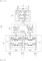
- FIG. 1 is a schematic configuration diagram illustrating a power converter according to an embodiment.
- a power converter 100 includes a direct current (DC) to alternating current (AC) converter 110, a Scott-T transformer 120, and an alternating current (AC) to direct current (DC) converter 130.
- DC direct current
- AC alternating current
- DC direct current
- the DC to AC converter 110 includes two multilevel converters 111 and 112.
- Each of the two multilevel converters 111 and 112 converts input direct current (DC) power to alternating current (AC) power.
- the multilevel converters 111 and 112 are module type multilevel converters.
- Each of the multilevel converters 111 and 112 includes first DC terminals P1 and N1 and second DC terminals P2 and N2.
- Each of the first and second multilevel converters 111 and 112 are configured with four arms ARM, and each of the arms ARM is implemented by a series connection of sub modules SM connected with arm inductors (Larm) in series.
- a first arm may connect the terminals P 1 and A P1
- a second arm may connect the terminals N 1 and A N1
- a third arm may connect the terminals P 2 and A P2
- a fourth arm may connect the terminals N 2 and A N2 .
- Each of the first and second multilevel converters 111 and 112 includes branch A and branch B.
- the branch A includes a first arm in an upper portion, a second arm in a lower portion, and an arm inductor connected in series.
- the branch B includes a third arm in an upper portion, a fourth arm in a lower portion, and an arm inductor connected in series.
- the sub module SM may be implemented by a half bridge HB cell, a full bridge FB cell, or a combination of a half bridge and a full bridge.
- the arm ARM may be implemented by a series combination of sub-modules in which various types of sub-modules connected to the inductor Larm in series are combined.
- a bipolar medium voltage direct current (DC) (MVDC) network having a neutral line may be used on an MVDC side, and in the case in which three poles DC+, DCo, and DC- are provided, the DC terminal N 1 of the first multilevel converter 111 and the DC terminal P 2 of the second multilevel converter 112 may also be connected.
- the DC terminal P 1 of the first multilevel converter 111 may be connected to the pole DC+
- the DC terminal N 2 of the second multilevel converter 112 may be connected to the pole DC-
- the DC terminal N 1 of the first multilevel converter 111 and the DC terminal P 2 of the second multilevel converter 112 may be connected to DCo.
- the AC terminal of the first multilevel converter 111 is connected to a first primary winding wire P 1 (A P1 to A N1 ) of a first transformer T 1 of the Scott-T transformer 120, and the AC terminal of the second multilevel converter 112 is connected to a second primary winding wire P 2 of a second transformer T 2 (A P2 -A N2 ) of the Scott-T transformer 120.
- a first secondary winding wire S 1 of the first transformer T 1 is a first terminal B P1 and a second terminal B N1 .
- a second secondary winding wire S 2 of the second transformer T 2 is a first terminal B P2 , a second terminal B O2 , and a third terminal B N2
- the second terminal B O2 is a central tap connection between the first terminal B P2 and the third terminal B N2
- the second terminal B N1 of the first secondary winding wire S 1 of the first transformer T 1 is connected to the second terminal B O2 of the second secondary winding wire S 2 of the second transformer T 2 .
- the first and second multilevel converters 111 and 112 employ the sub modules SM.
- the number of the sub modules SM may vary depending on a usable voltage level of the MVDC network, a selected voltage class of a semiconductor used to implement the sub modules SM, and a specific control margin irrelevant to a basic operational principle of a converter.
- the sub module SM may be implemented by an active semiconductor device, and the active semiconductor device may allow freedom related to selection of an operational frequency of the first and second transformers T 1 and T 2 used in the Scott-T transformer 120.
- An exact operational frequency may be determined by optimization of a design based on various parameters, and generally, an operational frequency ranging from several hundreds of Hz to several kHz may be achieved by a high-tech semiconductor device.
- the number of the sub modules SM of the first and second multilevel converters 111 and 112 may be further reduced, but an allowable operational frequency may be limited to be less than several tens of kHz.
- the number of the sub modules SM of the first and second multilevel converters 111 and 112 may increase, but a higher switching frequency may be available.
- FIG. 2 is a diagram illustrating a voltage phase of a Scott-T transformer employed in a power converter according to an embodiment.
- a Scott-T transformer 120 is implemented by using two double winding transformers T 1 and T 2 .
- Each of the transformers T 1 and T 2 , first and second transformers T 1 and T 2 include a single primary winding wire Pk and a single secondary winding wire S k (k indicates 1 or 2 and winding wires of T 1 and T 2 ) .
- a second secondary winding wire S 2 of the second transformer T 2 is divided into two portions. The number of winding wires of the two portions is N/2, a central tap connection is available accordingly, and the two portions are connected to a lower end of a first secondary winding wire S 1 of the first transformer T 1 .
- An upper end of the first secondary winding wire S 1 of the first transformer T 1 and upper and lower ends of the second secondary winding wire S 2 of the second transformer T 2 are used as secondary side terminals of the Scott-T transformer 120 indicated by A, B and C.
- the number of the first secondary winding wire S 1 of the first transformer T 1 may be set to N 3 2 to secure a normal operation of the Scott-T transformer 120.
- Line-to-line voltages VAB, VBC and VCA of a secondary side terminal of the Scott-T transformer 120 may be a balanced three phase having a phase difference of 120 degrees, whereas voltages V T1 and V T2 of a primary side terminal of the Scott-T transformer 120 may be a single phase having a phase difference of 90 degrees.
- the Scott-T transformer 120 operates in medium frequency of several hundreds of Hz to several tens of kHz.
- the regular Scott-Transformer mentioned in the present disclosure When the regular Scott-Transformer mentioned in the present disclosure is used in European railways, 16 and 2/3 Hz, 50Hz or 60Hz may be used as a use frequency in European railways.
- a Scott-T transformer When a Scott-T transformer operates in commercial frequency of 50Hz or 60Hz, a volume and a weight may increase.
- the Scott-T transformer 120 of the present disclosure may operate in medium frequency of several hundreds of Hz to several tens of kHz such that a volume and a weight may be reduced to several tens % as compared to a Scott-T transformer operating in commercial frequency.
- the Scott-T transformer When the Scott-T transformer operating in commercial frequency as in the prior art operates in frequency of several hundreds of Hz or less to several tens of kHz or higher, the Scott-T transformer may not operate properly, and the reduction of a size and a weight may not be effective. Thus, it may be necessary to develop a new Scott-T transformer by applying an appropriate core material or a winding wire to a Scott-T transformer to operate the Scott-T transformer in medium frequency. Also, when semiconductor properties of a AC-DC converter or a DC-AC converter is developed along with a Scott-T transformer, the Scott-T transformer may also operate in high frequency of several hundreds of kHz or higher.
- the DC to AC converter 110 and the AC to DC converter 130 also operates in medium frequency of several hundreds of Hz to several tens of kHz.
- the DC to AC converter 110 may convert bipolar direct current power or unipolar direct current power into two single phase alternating current powers having a phase difference of 90 degrees, and the Scott-T transformer 120 may convert the two single phase alternating current powers into three-phase alternating current power, and the AC to DC converter 130 may convert the three-phase alternating current power into a unipolar direct current power.
- Each of the AC to DC converters 130 includes three legs connected to one another in parallel, each having two semiconductor switches S 1 and S 4 , S 3 and S 6 , and S 5 and S 2 , connected to each other in series with middle point accessible.
- the AC to DC converter 130 includes DC terminals, a first DC terminal P 3 and a second DC terminal N 3 , and includes AC terminals, a first AC terminal A, a secondAC terminal AB, and a third AC terminal C.
- the AC terminal of the AC to DC converter 130 is connected to secondary side terminals of the Scott-T transformer 120, which are B P1 , B P2 , and B N2 .
- a filter, a capacitor bank, may be disposed in a region of the DC terminal of the AC to DC converter 130.
- An AC to DC converter 130 may operate in a square wave voltage to significantly reduce switching loss.
- each of the three legs may receive alternating current power of each of phases of the three-phase alternating current power from a Scott-T transformer 120, and the three legs may operate by six-step operation and may transfer the power bidirectionally.
- the AC to DC converter 130 receives the three-phase alternating current power from the Scott-T transformer 120 and has three legs, such that the number of devices may be reduced as compared to a case in which the AC to DC converter receives two single-phase alternating current from two normal transformers, which has two H-bridges.
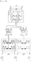
- FIG. 3 is a schematic configuration diagram illustrating a power converter according to another example not covered by the claims.
- a power converter 200 may include an alternating current (AC) to direct current (DC) converter 230 configured differently from the AC to DC converter 130, as compared to the power converter 100 according to the aforementioned embodiment in FIG. 1 .
- AC alternating current
- DC direct current
- the AC to DC converter 230 of the power converter 200 in another example not covered by the claims may include three legs connected to one another in parallel, each having two diodes D 1 and D 4 , D 3 and D 6 , and D 5 and D 2 , connected to each other in series with middle point accessible, as compared to the AC to DC converter 130 of the power converter 100 illustrated in FIG. 1 . Accordingly, power may be transferred unidirectionally.
- the AC to DC converter 230 may receive three-phase alternating current power from the Scott-T transformer 220 and may include three legs. Accordingly, the number of devices may be reduced as compared to a case in which the AC to DC converter includes two H-bridges, and a square wave may be rectified, and efficiency may increase.
- First and second multilevel converters 211 and 212 may operate to provide sinusoidal or square wave voltages VMMC1 and VMMC2 from AC terminals of the first and second multilevel converters 211 and 212 to a primary winding wire of the Scott-T transformer 220.
- a fundamental frequency of the voltages VMMC1 and VMMC2 may define operational frequencies of first and second transformers T1 and T2 of the Scott-T transformer 220.
- a magnitude of a voltage applied to the first and second transformers T1 and T2 may need to be adjusted.
- Voltages VT1 and VT2 of the first and second transformers T 1 and T 2 may need to be generated with a phase shift equal to 1/4 of a fundamental interval (90 degrees electrical degree), and line to line voltages VAB, VBC, and VCA of a secondary winding wire of a Scott-T transformer 320 may be symmetrical to one another.
- FIGS. 4A to 4D are conceptual circuit diagrams illustrating overall operations of a power converter and voltage-current waveform graphs according to an embodiment.
- FIGS. 4A to 4D equivalent circuits of first and second multilevel converters 211 and 212 connected to first and second transformers T 1 and T 2 , respectively, are illustrated in FIG. 4A .
- a phase difference ⁇ between the voltage VMMC1 of the first multilevel converter 111 and a voltage V T1 of a first primary winding wire P 1 of a relevant first transformer T 1 , and between the voltage VMMC2 of the second multilevel converter 112 and a voltage V T2 of a second primary winding wire P 2 of the relevant second transformer may be calculated.
- the voltage VMMC1 of the first multilevel converter 111 and the voltage VMMC2 of the second multilevel converter 112 may be controlled to be synchronized to a waveform generated by an AC to DC converter 130 in the AC terminals thereof, in VAB, VBC and VCA.
- Signals related to a leg of the AC to DC converter 130 may be phase-shifted from each other by 1/3 of a fundamental period.
- voltage waveforms of AC terminals A, B and C may be generated such that phases of the voltage waveforms are not matched with one another in two separate voltage levels 0 and Vo in relation to a DC terminal N 3 by a phase of each of legs of the AC to DC converter 130.
- the AC terminals VAB, VBC and VCA of the AC to DC converter 130 in the above reference line may have a voltage of three-level form (as a result of direct deduction of both leg voltages) having levels of Vo, 0 and -Vo (please see FIG. 4B ).
- V T1 the voltage of the first primary winding wire P 1 of the first transformer T 1
- V T2 the voltage of the second primary winding wire P 2 of the second transformer T 2
- m 1 indicates a turns ratio between primary and secondary winding turns of a transformer T 1
- m 2 indicates a turns ratio between primary and secondary winding turns of a transformer T 2 .
- FIGS. 4C and 4D show waveforms generated by the first and second multilevel converters 111 and 112 and currents iT 1 and iT 2 flowing through primary winding wires P 1 and P 2 of each of the first and second transformers T 1 and T 2 .
- the power converter according to the embodiment may have a technical effect as below.
- FIG. 5 is graphs illustrating voltage waveforms of a power converter according to another example embodiment.
- a phase difference between voltages V T1 and V T2 may not be perfect, and there is a small phase difference, a voltage imbalance generated in each leg of the AC to DC converter 230 may not affect an output voltage.
- a turns ratio of the transformer or an imbalance of phase shifts may not affect an operation, due to absence of magnetic coupling between two single-phase transformers.
- An output voltage VO may have a typical waveform of a 6-pulse diode rectifier.
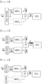
- FIGS. 6A to 6D are conceptual diagrams illustrating an operation performed when a bipolar grid or a plurality of unipolar grids are input in a power converter and a partial operation performed when one pole is out of service.
- first and second multilevel converters may be connected in series as illustrated in the diagram.
- FIG. 6B illustrates a redundancy principle of when one of the multilevel converters has a fault, or when power is not supplied as one pole of an external grid is out of service.
- the pole having a fault may be isolated from a circuit, and the other inductor may continue to operate at a half of rated power.
- the first and second multilevel converters may operate independently (synchronized to a Scott-T transformer) .
- FIG. 6D illustrates a redundancy principle of when one of the unipolar grids has a fault.
- the pole having a fault may be isolated from a circuit, and the other may continue to operate at half of rated power.
- FIGS. 7A to 7D are diagrams illustrating a power converter according to either an embodiment or en example not covered by the claims and a partial operation performed when one pole of a bipolar grid is out of service in a power converter.
- FIGS. 7A to 7D another aspect of the present disclosure is that, in the case of a bidirectional power converter or a unidirectional power converter in FIG. 1 or FIG. 3 , a system level of a redundancy may be implemented in an MVDC side.
- a bipolar network having a neutral line may be used, and in this case, a DC terminal P 1 of a first multilevel converter may be connected to a pole DC+, a DC terminal N 2 of a second multilevel converter may be connected to a pole DC-, and a DC terminal N1 of the first multilevel converter and a DC terminal P 2 of the second multilevel converter may be connected to DC0.
- a half of the system may continuously operate in an abnormal mode through the other pole.
- the multilevel converter having a fault may be isolated from the remaining portion of a circuit, and thus, the relevant transformer (in FIGS. 7A to 7C , the second transformer T 2 ) may operate based on a bypass connection circuit providing a small winding leakage inductance. Although one of three legs in an alternating current (AC) to direct current (DC) converter may not function properly, the remaining two legs may continue to operate in a similar manner to that of a single phase DAB.
- AC alternating current
- DC direct current
Landscapes
- Engineering & Computer Science (AREA)
- Power Engineering (AREA)
- Inverter Devices (AREA)
- Ac-Ac Conversion (AREA)
Description
- The present disclosure relates to a power converter having a Scott-T transformer.
- Generally, a power converter is used in structures and vehicles such as marine plants, ships, trains, and the like.
- Such structures and vehicles, such as marine plants, ships, trains, and the like, may require various power levels, and to this end, a high power direct current (DC)-alternating current (AC) converter or a high power direct current (DC)-direct current (DC) converter may be provided.
- In the aforementioned power converter, a transformer, a plurality of multilevel converters, and the like, may be employed. However, a current increase may occur in at least one of the plurality of multilevel converters due to current imbalance in a transformer, and a power converter may not operate properly.
-
-
- XIANG XIN ET AL: The isolated resonant modular multilevel converters with large step-ratio for MVDC applications", 2017 IEEE 18TH WORKSHOP ON CONTROL AND MODELING FOR POWER ELECTRONICS (COMPEL), IEEE, 9 July 2017 (2017-07-09), pages 1-6, XP033144082, presents two isolated resonant modular multilevel converters (IRMMCs) to fulfil the large step-ratio conversion for medium voltage dc (MVDC) networks.
-
EP 2 192 679 A1 - An aspect of the present disclosure is to provide a power converter having a Scott-T transformer employed therein.
- The invention is defined in the independent claim. Preferred embodiments are defined in the dependent claims.
- According to an example of the present disclosure, even when a fault occurs in a multilevel converter, normal power conversion may be performed, an effect of the present disclosure.
-
-
FIG. 1 is a schematic configuration diagram illustrating a power converter according to an embodiment of the present disclosure; -
FIG. 2 is a diagram illustrating a voltage phase of a Scott-T transformer employed in a power converter according to an embodiment of the present disclosure; -
FIG. 3 is a schematic configuration diagram illustrating a power converter according to an example not covered by the claims; -
FIGS. 4A to 4D are conceptual circuit diagrams illustrating overall operations of a power converter and voltage-current waveform graphs according to an embodiment of the present disclosure; -
FIG. 5 is graphs illustrating voltage waveforms of a power converter according to an embodiment of the present disclosure or an example not covered by the claims; -
FIGS. 6A to 6D are conceptual diagrams illustrating an operation performed when a bipolar grid or a plurality of unipolar grids are input in a power converter and a partial operation performed under the outage of one of the poles; and -
FIGS. 7A and7B are diagrams illustrating a power converter according to an embodiment and a partial operation performed when one pole of a bipolar grid is broken in a power converter; -
FIGS. 7C and7D are diagrams illustrating a power converter according to an example not covered by the claims and a partial operation performed when one pole of a bipolar grid is broken in a power converter. - Hereinafter, embodiments of the present disclosure will be described in greater detail for a person having ordinary skill in the art to easily implement the present disclosure.
-
FIG. 1 is a schematic configuration diagram illustrating a power converter according to an embodiment. - Referring to
FIG. 1 , apower converter 100 according to an embodiment includes a direct current (DC) to alternating current (AC)converter 110, a Scott-T transformer 120, and an alternating current (AC) to direct current (DC)converter 130. - The DC to
AC converter 110 includes twomultilevel converters - Each of the two
multilevel converters multilevel converters - Each of the
multilevel converters - Each of the first and
second multilevel converters multilevel converters 111, a first arm may connect the terminals P1 and AP1, a second arm may connect the terminals N1 and AN1, a third arm may connect the terminals P2 and AP2, and a fourth arm may connect the terminals N2 and AN2. Each of the first andsecond multilevel converters - The sub module SM may be implemented by a half bridge HB cell, a full bridge FB cell, or a combination of a half bridge and a full bridge. The arm ARM may be implemented by a series combination of sub-modules in which various types of sub-modules connected to the inductor Larm in series are combined.
- A bipolar medium voltage direct current (DC) (MVDC) network having a neutral line may be used on an MVDC side, and in the case in which three poles DC+, DCo, and DC- are provided, the DC terminal N1 of the
first multilevel converter 111 and the DC terminal P2 of thesecond multilevel converter 112 may also be connected. In this case, the DC terminal P1 of thefirst multilevel converter 111 may be connected to the pole DC+, the DC terminal N2 of thesecond multilevel converter 112 may be connected to the pole DC-, and the DC terminal N1 of thefirst multilevel converter 111 and the DC terminal P2 of thesecond multilevel converter 112 may be connected to DCo. - The AC terminal of the
first multilevel converter 111 is connected to a first primary winding wire P1 (AP1 to AN1) of a first transformer T1 of the Scott-T transformer 120, and the AC terminal of thesecond multilevel converter 112 is connected to a second primary winding wire P2 of a second transformer T2 (AP2-AN2) of the Scott-T transformer 120. A first secondary winding wire S1 of the first transformer T1 is a first terminal BP1 and a second terminal BN1. A second secondary winding wire S2 of the second transformer T2 is a first terminal BP2, a second terminal BO2, and a third terminal BN2, and the second terminal BO2 is a central tap connection between the first terminal BP2 and the third terminal BN2. Also, the second terminal BN1 of the first secondary winding wire S1 of the first transformer T1 is connected to the second terminal BO2 of the second secondary winding wire S2 of the second transformer T2. - To interface the MVDC network, the first and
second multilevel converters - For example, the sub module SM may be implemented by an active semiconductor device, and the active semiconductor device may allow freedom related to selection of an operational frequency of the first and second transformers T1 and T2 used in the Scott-T
transformer 120. An exact operational frequency may be determined by optimization of a design based on various parameters, and generally, an operational frequency ranging from several hundreds of Hz to several kHz may be achieved by a high-tech semiconductor device. - In the case in which a high voltage semiconductor (e.g., 6.5kV) is used, the number of the sub modules SM of the first and
second multilevel converters second multilevel converters -
FIG. 2 is a diagram illustrating a voltage phase of a Scott-T transformer employed in a power converter according to an embodiment. - Referring to
FIG. 2 , a Scott-T transformer 120 is implemented by using two double winding transformers T1 and T2. Each of the transformers T1 and T2, first and second transformers T1 and T2, include a single primary winding wire Pk and a single secondary winding wire Sk (k indicates 1 or 2 and winding wires of T1 and T2) . A second secondary winding wire S2 of the second transformer T2 is divided into two portions. The number of winding wires of the two portions is N/2, a central tap connection is available accordingly, and the two portions are connected to a lower end of a first secondary winding wire S1 of the first transformer T1. - An upper end of the first secondary winding wire S1 of the first transformer T1 and upper and lower ends of the second secondary winding wire S2 of the second transformer T2 are used as secondary side terminals of the Scott-
T transformer 120 indicated by A, B and C. The number of the first secondary winding wire S1 of the first transformer T1 may be set to
T transformer 120. - Consequently, by configuring the number of the first primary winding turns P1 of the first transformer T1 and the number of the second primary winding turns P2 of the second transformer T2 to be the same, a turns ratio relation may be induced to be

- Line-to-line voltages VAB, VBC and VCA of a secondary side terminal of the Scott-
T transformer 120 may be a balanced three phase having a phase difference of 120 degrees, whereas voltages VT1 and VT2 of a primary side terminal of the Scott-T transformer 120 may be a single phase having a phase difference of 90 degrees. - The Scott-T
transformer 120 operates in medium frequency of several hundreds of Hz to several tens of kHz. - When the regular Scott-Transformer mentioned in the present disclosure is used in European railways, 16 and 2/3 Hz, 50Hz or 60Hz may be used as a use frequency in European railways. When a Scott-T transformer operates in commercial frequency of 50Hz or 60Hz, a volume and a weight may increase. Differently from the above-described example, the Scott-
T transformer 120 of the present disclosure may operate in medium frequency of several hundreds of Hz to several tens of kHz such that a volume and a weight may be reduced to several tens % as compared to a Scott-T transformer operating in commercial frequency. When the Scott-T transformer operating in commercial frequency as in the prior art operates in frequency of several hundreds of Hz or less to several tens of kHz or higher, the Scott-T transformer may not operate properly, and the reduction of a size and a weight may not be effective. Thus, it may be necessary to develop a new Scott-T transformer by applying an appropriate core material or a winding wire to a Scott-T transformer to operate the Scott-T transformer in medium frequency. Also, when semiconductor properties of a AC-DC converter or a DC-AC converter is developed along with a Scott-T transformer, the Scott-T transformer may also operate in high frequency of several hundreds of kHz or higher. - The DC to
AC converter 110 and the AC toDC converter 130 also operates in medium frequency of several hundreds of Hz to several tens of kHz. - The DC to
AC converter 110 may convert bipolar direct current power or unipolar direct current power into two single phase alternating current powers having a phase difference of 90 degrees, and the Scott-T transformer 120 may convert the two single phase alternating current powers into three-phase alternating current power, and the AC toDC converter 130 may convert the three-phase alternating current power into a unipolar direct current power. - Each of the AC to
DC converters 130 includes three legs connected to one another in parallel, each having two semiconductor switches S1 and S4, S3 and S6, and S5 and S2, connected to each other in series with middle point accessible. - The AC to
DC converter 130 includes DC terminals, a first DC terminal P3 and a second DC terminal N3, and includes AC terminals, a first AC terminal A, a secondAC terminal AB, and a third AC terminal C. The AC terminal of the AC toDC converter 130 is connected to secondary side terminals of the Scott-T transformer 120, which are BP1, BP2, and BN2. A filter, a capacitor bank, may be disposed in a region of the DC terminal of the AC toDC converter 130. - An AC to
DC converter 130 may operate in a square wave voltage to significantly reduce switching loss. - When the AC to
DC converter 130 is configured to have three legs connected to one another in parallel, each having the two semiconductor switches S1 and S4, S3 and S6, and S5 and S2, connected to each other in series with middle point accessible, each of the three legs may receive alternating current power of each of phases of the three-phase alternating current power from a Scott-T transformer 120, and the three legs may operate by six-step operation and may transfer the power bidirectionally. - The AC to
DC converter 130 receives the three-phase alternating current power from the Scott-T transformer 120 and has three legs, such that the number of devices may be reduced as compared to a case in which the AC to DC converter receives two single-phase alternating current from two normal transformers, which has two H-bridges. -
FIG. 3 is a schematic configuration diagram illustrating a power converter according to another example not covered by the claims. - Referring to
FIG. 3 along withFIG. 1 , apower converter 200 according to another example not covered by the claims may include an alternating current (AC) to direct current (DC)converter 230 configured differently from the AC toDC converter 130, as compared to thepower converter 100 according to the aforementioned embodiment inFIG. 1 . - The AC to
DC converter 230 of thepower converter 200 in another example not covered by the claims may include three legs connected to one another in parallel, each having two diodes D1 and D4, D3 and D6, and D5 and D2, connected to each other in series with middle point accessible, as compared to the AC toDC converter 130 of thepower converter 100 illustrated inFIG. 1 . Accordingly, power may be transferred unidirectionally. Similarly, the AC toDC converter 230 may receive three-phase alternating current power from the Scott-T transformer 220 and may include three legs. Accordingly, the number of devices may be reduced as compared to a case in which the AC to DC converter includes two H-bridges, and a square wave may be rectified, and efficiency may increase. - There may be no phase change in relation to an MVDC side interface and the Scott-T transformer in the
power converter 200, but an operational principle of thepower converter 200 may be slightly different from an operational principle of thepower converter 100 illustrated inFIG. 1 . - Instead of controlling phase between voltages of DC-AC converter and AC-DC converter, only voltage of DC-AC converter needs to be controlled. First and second
multilevel converters multilevel converters T transformer 220. A fundamental frequency of the voltages VMMC1 and VMMC2 may define operational frequencies of first and second transformers T1 and T2 of the Scott-T transformer 220. To control an output voltage, a magnitude of a voltage applied to the first and second transformers T1 and T2 may need to be adjusted. Voltages VT1 and VT2 of the first and second transformers T1 and T2 may need to be generated with a phase shift equal to 1/4 of a fundamental interval (90 degrees electrical degree), and line to line voltages VAB, VBC, and VCA of a secondary winding wire of a Scott-T transformer 320 may be symmetrical to one another. - The other descriptions of the direct current (DC) to alternating current (AC)
converter 210 and the Scott-T transformer 220 are the same as or similar to the descriptions of the direct current (DC) to alternating current (AC)converter 110 and the Scott-T transformer 120 of thepower converter 100 in the aforementioned embodiment, and thus, the detailed descriptions thereof will not be repeated. -
FIGS. 4A to 4D are conceptual circuit diagrams illustrating overall operations of a power converter and voltage-current waveform graphs according to an embodiment. - Referring to
FIGS. 4A to 4D along withFIG. 1 , equivalent circuits of first and secondmultilevel converters FIG. 4A . - As illustrated in
FIG. 4A , by adjusting phase shifts of a voltage waveform VMMC1 (a voltage between branch A and branch B of the first multilevel converter 111) and a voltage waveform VMMC2 (a voltage between branch A and branch B of second multilevel converter 112) with respect to voltages (provided by the AC to DC converter 130) generated from the secondary side, currents of the first and second transformers T1 and T2 may be controlled. - A phase difference ϕ between the voltage VMMC1 of the first
multilevel converter 111 and a voltage VT1 of a first primary winding wire P1 of a relevant first transformer T1, and between the voltage VMMC2 of the secondmultilevel converter 112 and a voltage VT2 of a second primary winding wire P2 of the relevant second transformer may be calculated. In this case, the voltage VMMC1 of the firstmultilevel converter 111 and the voltage VMMC2 of the secondmultilevel converter 112 may be controlled to be synchronized to a waveform generated by an AC toDC converter 130 in the AC terminals thereof, in VAB, VBC and VCA. - Signals related to a leg of the AC to
DC converter 130 may be phase-shifted from each other by 1/3 of a fundamental period. In this manner, voltage waveforms of AC terminals A, B and C may be generated such that phases of the voltage waveforms are not matched with one another in two separate voltage levels 0 and Vo in relation to a DC terminal N3 by a phase of each of legs of the AC toDC converter 130. The AC terminals VAB, VBC and VCA of the AC toDC converter 130 in the above reference line may have a voltage of three-level form (as a result of direct deduction of both leg voltages) having levels of Vo, 0 and -Vo (please seeFIG. 4B ). - The above voltage may correspond to the line-to-line voltages VAB, VBC and VCA of the AC terminal of the AC to
DC converter 130. VT1 (the voltage of the first primary winding wire P1 of the first transformer T1) and VT2 (the voltage of the second primary winding wire P2 of the second transformer T2) may be calculated by equations as below.
- In the equation, m1 indicates a turns ratio between primary and secondary winding turns of a transformer T1, and m2 indicates a turns ratio between primary and secondary winding turns of a transformer T2.
-
FIGS. 4C and4D show waveforms generated by the first and secondmultilevel converters - and may be calculated on the basis of a relation of turns ratios the transformers, the equations, and
FIG. 4B . In the case in which an output voltage is Vo,

- Accordingly, the power converter according to the embodiment may have a technical effect as below.
- 1. The number of semiconductor devices may be reduced: The DC to AC converter may use two single-phase multilevel converters instead of using two three-phase multilevel converters. As a result, the number of semiconductor devices may be decreased to 2/3 so that a size of the converter may be reduced. Although current capacitance of the device may increase, the increase may be alleviated greatly as complexity of a circuit of the alternating current (AC) to direct current (DC) converter is significantly reduced.
- 2. A small-sized transformer for galvanic insulation may be used: When a Scott-T transformer is used, the number of required windings of a system may be reduced to 1/4 so that a system may be manufactured to have a compact size, and the system may be applied to a certain application such as railways. Also, a design of a transformer may be simplified.
- 3. A size of a system may be reduced: When a power converter operates in a high fundamental frequency, a size (a volume and a weight) of a Scott-T transformer operating in a medium frequency may be reduced.
- 4. A rectifier may operate: The Scott-T transformer in the example not covered by the claims may use two transformers connected to different cores, and thus, a diode rectifier may be applied.
-
FIG. 5 is graphs illustrating voltage waveforms of a power converter according to another example embodiment. - Referring to
FIG. 5 , even though a phase difference between voltages VT1 and VT2 may not be perfect, and there is a small phase difference, a voltage imbalance generated in each leg of the AC toDC converter 230 may not affect an output voltage. According to the topology of a unidirectional power converter, a turns ratio of the transformer or an imbalance of phase shifts may not affect an operation, due to absence of magnetic coupling between two single-phase transformers. An output voltage VO may have a typical waveform of a 6-pulse diode rectifier. -
FIGS. 6A to 6D are conceptual diagrams illustrating an operation performed when a bipolar grid or a plurality of unipolar grids are input in a power converter and a partial operation performed when one pole is out of service. - Referring to
FIG. 6A , when a bipolar grid is provided, first and second multilevel converters may be connected in series as illustrated in the diagram.FIG. 6B illustrates a redundancy principle of when one of the multilevel converters has a fault, or when power is not supplied as one pole of an external grid is out of service. The pole having a fault may be isolated from a circuit, and the other inductor may continue to operate at a half of rated power. - However, as illustrated in
FIG. 6C , when two unipolar grids are used, the first and second multilevel converters may operate independently (synchronized to a Scott-T transformer) . -
FIG. 6D illustrates a redundancy principle of when one of the unipolar grids has a fault. The pole having a fault may be isolated from a circuit, and the other may continue to operate at half of rated power. -
FIGS. 7A to 7D are diagrams illustrating a power converter according to either an embodiment or en example not covered by the claims and a partial operation performed when one pole of a bipolar grid is out of service in a power converter. - Referring to
FIGS. 7A to 7D , another aspect of the present disclosure is that, in the case of a bidirectional power converter or a unidirectional power converter inFIG. 1 orFIG. 3 , a system level of a redundancy may be implemented in an MVDC side. - A bipolar network having a neutral line may be used, and in this case, a DC terminal P1 of a first multilevel converter may be connected to a pole DC+, a DC terminal N2 of a second multilevel converter may be connected to a pole DC-, and a DC terminal N1 of the first multilevel converter and a DC terminal P2 of the second multilevel converter may be connected to DC0.
- When one multilevel converter or one of at least two multilevel converters have a fault in the MVDC side, or when power is not supplied as one pole of an external grid is out of service, a half of the system may continuously operate in an abnormal mode through the other pole.
- The multilevel converter having a fault may be isolated from the remaining portion of a circuit, and thus, the relevant transformer (in
FIGS. 7A to 7C , the second transformer T2) may operate based on a bypass connection circuit providing a small winding leakage inductance. Although one of three legs in an alternating current (AC) to direct current (DC) converter may not function properly, the remaining two legs may continue to operate in a similar manner to that of a single phase DAB. - While the embodiments have been shown and described above, it will be apparent to those skilled in the art that modifications and variations could be made without departing from the scope of the present invention as defined by the appended claims.
Claims (5)
- A power converter having a Scott-T transformer, comprising:a direct current to alternating current converter (110) that comprises first and second multilevel converters (111, 112) configured to convert input direct current power to alternating current power;the Scott-T transformer (120) configured to operate in medium frequency of several hundreds of Hz to several tens of kHz, to transform a voltage level of the alternating current power from each of the first and second multilevel converters of the direct current to alternating current converter into three-phase alternating current power, and to output the three-phase alternating current power; andan alternating current to direct current converter (130) configured to convert the three-phase alternating current power from the Scott-T transformer to direct current power;wherein each of the first and second multilevel converters (111, 112) comprises four arms (ARM),each of the arms (ARM) comprises a series connection of sub-modules (SM) connected with arm inductors (Larm) in series, the first and second multilevel converters (111, 112) include a first branch (A) and a second branch (B),wherein the first branch (A) includes a first arm in an upper portion, a second arm in a lower portion, and an arm inductor connected in series,wherein the second branch (B) includes a third arm in an upper portion, a fourth arm in a lower portion, and an arm inductor connected in series,wherein an AC terminal of the first multilevel converter (111) is connected to a first primary winding wire (P1) of a first transformer (T1) of the Scott-T transformer (120), and an AC terminal of the second multilevel converter (112) is connected to a second primary winding wire (P2) of a second transformer (T2) of the Scott-T transformer (120),wherein the alternating current to direct current converter (130) includes AC terminals connected to secondary side terminals of the Scott-T transformer (120), whereina first secondary winding wire (S1) of the first transformer (T1) comprises a first terminal (BP1) and a second terminal (BN1),a second secondary winding wire (S2) of the second transformer (T2) comprises a first terminal (BP2), a second terminal (B02), and a third terminal (BN2), andthe second terminal (B02) is a central tap connection between the first terminal (BP2) and the third terminal (BN2),the second terminal (BN1) of the first secondary winding wire (S1) of the first transformer (T1) is connected to the second terminal (B02) of the second secondary winding wire (S2) of the second transformer (T2),wherein the first and second multilevel converters (111, 112) of the direct current to alternating current converter are configured to convert an input direct current medium voltage and direct current power of a bipolar grid into an alternating current medium voltage and two phase alternating current powers having a medium frequency,wherein the first and second multilevel converters (111, 112) of the direct current to alternating current converter are connectable to a Medium Voltage Direct Current (MVDC) network including a bipolar grid having a neutral line and comprising three poles (DC+, DCo, and DC-), wherein one terminal (N1) of the first multilevel converter (111) is connected to one terminal (P2) of the second multilevel converter (112),another terminal (P1) of the first multilevel converter (111) is connectable to a first pole (DC+),another terminal (N2) of the second multilevel converter (112) is connectable to a second pole (DC-), andthe terminal (N1) of the first multilevel converter (111) and the terminal (P2) of the second multilevel converter (112) are connectable to a third pole (DCo),wherein the alternating current to direct current converter (130) includes three legs connected to one another in parallel, each having two semiconductor switches connected to each other in series,wherein the three legs of the alternating current to direct current converter (130) are configured to operate by six-step operation, andwherein the power converter is configured to operate as a bidirectional power converter.
- The power converter of claim 1, wherein the Scott-T transformer (120) is configured to convert the alternating current power from the direct current to alternating current converter (110) into the three-phase alternating current power of a low voltage of several kV or lower in accordance with a predetermined turn ratio.
- The power converter of claim 2, wherein the alternating current to direct current converter (130) is configured to convert alternating current power from the Scott-T transformer (120) into direct current power of a low voltage of 1500V or lower.
- The power converter of claim 1, wherein the alternating current to direct current converter (130) is configured to operate in a medium frequency of several hundreds of Hz to several tens of kHz.
- The power converter of claim 1, wherein each of the sub-modules of the first and second multilevel converters (111, 112) includes a half bridge, a full bridge, or combination of a half bridge and a full bridge.
Applications Claiming Priority (3)
| Application Number | Priority Date | Filing Date | Title |
|---|---|---|---|
| KR20180050472 | 2018-05-02 | ||
| KR1020190049955A KR102235397B1 (en) | 2018-05-02 | 2019-04-29 | Power converting apparatus having scott transformer |
| PCT/KR2019/005262 WO2019212257A1 (en) | 2018-05-02 | 2019-05-02 | Power conversion apparatus having scott transformer |
Publications (4)
| Publication Number | Publication Date |
|---|---|
| EP3651343A1 EP3651343A1 (en) | 2020-05-13 |
| EP3651343A4 EP3651343A4 (en) | 2020-11-18 |
| EP3651343C0 EP3651343C0 (en) | 2025-04-16 |
| EP3651343B1 true EP3651343B1 (en) | 2025-04-16 |
Family
ID=68577356
Family Applications (1)
| Application Number | Title | Priority Date | Filing Date |
|---|---|---|---|
| EP19796080.0A Active EP3651343B1 (en) | 2018-05-02 | 2019-05-02 | Power conversion apparatus having scott transformer |
Country Status (4)
| Country | Link |
|---|---|
| US (1) | US11025171B2 (en) |
| EP (1) | EP3651343B1 (en) |
| KR (1) | KR102235397B1 (en) |
| CN (1) | CN111052588B (en) |
Families Citing this family (7)
| Publication number | Priority date | Publication date | Assignee | Title |
|---|---|---|---|---|
| US11626809B1 (en) | 2018-03-02 | 2023-04-11 | Apple Inc. | Multilevel power converters |
| KR102279748B1 (en) | 2019-11-28 | 2021-07-20 | (주) 오디피 | The smps including a transformer apparatus with adjustable output voltage |
| CN112187060A (en) * | 2020-10-26 | 2021-01-05 | 国网江苏省电力有限公司电力科学研究院 | Isolated low-voltage direct current switching circuit, switching device and control method |
| WO2022271102A2 (en) * | 2021-06-23 | 2022-12-29 | Nanyang Technological University | System and method for stabilizing a power distribution network |
| US12542440B2 (en) | 2023-04-12 | 2026-02-03 | DG Matrix, Inc. | Resilient on-site microgrid system |
| US12620886B2 (en) | 2023-04-12 | 2026-05-05 | DG Matrix, Inc. | Multiport transformer enabled modular multiport power conversion system |
| US20240348171A1 (en) * | 2023-04-12 | 2024-10-17 | DG Matrix, Inc. | Multiport transformer enabled modular multiport power conversion system |
Family Cites Families (16)
| Publication number | Priority date | Publication date | Assignee | Title |
|---|---|---|---|---|
| US2458725A (en) | 1944-09-14 | 1949-01-11 | Glenn W Periman | Pliers |
| US2637296A (en) | 1950-06-13 | 1953-05-05 | Bendix Aviat Corp | Illuminated indicating apparatus |
| US7050311B2 (en) * | 2003-11-25 | 2006-05-23 | Electric Power Research Institute, Inc. | Multilevel converter based intelligent universal transformer |
| ITRE20040038A1 (en) * | 2004-04-22 | 2004-07-22 | Ask Ind Spa | THREE-PHASE DC / DC CONVERTER |
| CN101453171B (en) * | 2008-09-12 | 2011-09-28 | 清华大学 | United electric energy quality controller based on series multiplex of transformer and chain type construction |
| US8259468B2 (en) | 2008-11-28 | 2012-09-04 | Sma Solar Technology Ag | Three-phase inverter for converting DC power from a generator into three-phase AC power |
| EP2458725A1 (en) | 2010-11-30 | 2012-05-30 | ABB Research Ltd. | Electric energy conversion system and method for operating same |
| JP5679054B2 (en) | 2011-06-09 | 2015-03-04 | トヨタ自動車株式会社 | Power supply equipment for vehicles |
| EP2637296A1 (en) | 2012-03-06 | 2013-09-11 | Siemens Aktiengesellschaft | HVDC converter station with 2-phase modular multilevel converter and Scott-T 2 to 3 phase transformer |
| CN106998152B (en) | 2016-01-25 | 2019-10-18 | 华北电力大学 | Electrically isolated unidirectional DC-DC converter without voltage equalization control |
| EP3223419B1 (en) * | 2016-03-22 | 2019-05-01 | GE Energy Power Conversion Technology Ltd | Direct ac-ac converter assembly and conversion system using same |
| JP2017192297A (en) | 2016-04-07 | 2017-10-19 | 株式会社明電舎 | Multilevel power conversion device and method for controlling multilevel power conversion device |
| CN106300996A (en) * | 2016-08-24 | 2017-01-04 | 中铁第勘察设计院集团有限公司 | Transformator electric energy two or three phase inversion process |
| KR101843652B1 (en) | 2016-10-25 | 2018-03-29 | 한국철도기술연구원 | AC railway supply grid feed device using phase-shift transformer and method thereof |
| CN107546983B (en) * | 2017-01-17 | 2019-08-02 | 湖南大学 | An isolated high power high transformation ratio modular bidirectional DC converter |
| CN107565834B (en) * | 2017-07-25 | 2020-03-24 | 全球能源互联网研究院有限公司 | A kind of control method and device of AC-DC conversion circuit |
-
2019
- 2019-04-29 KR KR1020190049955A patent/KR102235397B1/en active Active
- 2019-05-02 US US16/634,490 patent/US11025171B2/en active Active
- 2019-05-02 CN CN201980003789.7A patent/CN111052588B/en active Active
- 2019-05-02 EP EP19796080.0A patent/EP3651343B1/en active Active
Non-Patent Citations (1)
| Title |
|---|
| ZHU HANG ET AL: "Topology and operation mechanism of monopolarto-bipolar DC-DC converter interface for DC grid", 2016 IEEE 8TH INTERNATIONAL POWER ELECTRONICS AND MOTION CONTROL CONFERENCE (IPEMC-ECCE ASIA), IEEE, 22 May 2016 (2016-05-22), pages 3728 - 3733, XP032924879, DOI: 10.1109/IPEMC.2016.7512892 * |
Also Published As
| Publication number | Publication date |
|---|---|
| EP3651343C0 (en) | 2025-04-16 |
| CN111052588B (en) | 2023-08-08 |
| EP3651343A1 (en) | 2020-05-13 |
| KR102235397B1 (en) | 2021-04-05 |
| CN111052588A (en) | 2020-04-21 |
| US20200186043A1 (en) | 2020-06-11 |
| EP3651343A4 (en) | 2020-11-18 |
| KR20190126718A (en) | 2019-11-12 |
| US11025171B2 (en) | 2021-06-01 |
Similar Documents
| Publication | Publication Date | Title |
|---|---|---|
| US11025171B2 (en) | Power conversion apparatus having Scott-T transformer | |
| RU2534027C2 (en) | Device for electric parameter conversion with zero-point reactor | |
| Lüth et al. | Modular multilevel DC/DC converter architectures for HVDC taps | |
| CN101938216B (en) | Power transmission method and power transmission apparatus | |
| EP2290799A1 (en) | Bi-directional multilevel AC-DC converter arrangements | |
| JP6404768B2 (en) | Power converter | |
| CN105379090A (en) | Modular Multilevel DC/DC Converter for High Voltage DC Applications | |
| US20090225570A1 (en) | Twelve-pulse HVDC Transmission | |
| US12136887B2 (en) | Multi-active bridge (MAB) converter and control method thereof and power conversion device | |
| CN112952845A (en) | Low-frequency power transmission system with transformer isolation and control method thereof | |
| CN104160607B (en) | Transformer configuration for HVDC back-to-back converters | |
| Mogstad et al. | Power collection and integration on the electric grid from offshore wind parks | |
| JP2009273355A (en) | Apparatus for transmitting electric power | |
| US20140204614A1 (en) | Rectified high frequency power supply with low total harmonic distortion (thd) | |
| KR101030632B1 (en) | Power Converter and Power Conversion System Using High Frequency Transformer | |
| Lüth et al. | A DC/DC converter suitable for HVDC applications with large step-ratios | |
| Lüth et al. | Choice of AC operating voltage in HV DC/AC/DC system | |
| Jones et al. | Construction and testing of a 13.8 kV, 750 kVA 3-Phase current compensator using modular switching positions | |
| US11012001B2 (en) | Transformer-less, tapped point AC voltage splitter for full bridge DC AC inverters | |
| WO2024069750A1 (en) | Electric power conversion system | |
| WO2018145748A1 (en) | Parallel connecting of cell modules in a modular multilevel converter by means of interphase transformers | |
| US12633816B1 (en) | Cascaded DC modular solid-state transformer | |
| Facchinello et al. | AC-AC dual active bridge converter for smart grid applications | |
| SU720621A1 (en) | Balancing device for connecting polyphase symmetrical load to asymmetrical polyphase supply network | |
| SU1767655A1 (en) | Alternating-to-constant voltage transformer |
Legal Events
| Date | Code | Title | Description |
|---|---|---|---|
| STAA | Information on the status of an ep patent application or granted ep patent |
Free format text: STATUS: THE INTERNATIONAL PUBLICATION HAS BEEN MADE |
|
| PUAI | Public reference made under article 153(3) epc to a published international application that has entered the european phase |
Free format text: ORIGINAL CODE: 0009012 |
|
| STAA | Information on the status of an ep patent application or granted ep patent |
Free format text: STATUS: REQUEST FOR EXAMINATION WAS MADE |
|
| 17P | Request for examination filed |
Effective date: 20200204 |
|
| AK | Designated contracting states |
Kind code of ref document: A1 Designated state(s): AL AT BE BG CH CY CZ DE DK EE ES FI FR GB GR HR HU IE IS IT LI LT LU LV MC MK MT NL NO PL PT RO RS SE SI SK SM TR |
|
| AX | Request for extension of the european patent |
Extension state: BA ME |
|
| A4 | Supplementary search report drawn up and despatched |
Effective date: 20201019 |
|
| RIC1 | Information provided on ipc code assigned before grant |
Ipc: H02M 7/483 20070101AFI20201013BHEP Ipc: H01F 27/42 20060101ALI20201013BHEP Ipc: H02M 3/335 20060101ALI20201013BHEP Ipc: H02M 5/14 20060101ALI20201013BHEP Ipc: H02M 7/04 20060101ALI20201013BHEP Ipc: H01F 30/14 20060101ALI20201013BHEP |
|
| STAA | Information on the status of an ep patent application or granted ep patent |
Free format text: STATUS: EXAMINATION IS IN PROGRESS |
|
| 17Q | First examination report despatched |
Effective date: 20210708 |
|
| DAV | Request for validation of the european patent (deleted) | ||
| DAX | Request for extension of the european patent (deleted) | ||
| GRAP | Despatch of communication of intention to grant a patent |
Free format text: ORIGINAL CODE: EPIDOSNIGR1 |
|
| STAA | Information on the status of an ep patent application or granted ep patent |
Free format text: STATUS: GRANT OF PATENT IS INTENDED |
|
| RIC1 | Information provided on ipc code assigned before grant |
Ipc: H01F 30/14 20060101ALI20241124BHEP Ipc: H01F 27/42 20060101ALI20241124BHEP Ipc: H02M 1/00 20060101ALI20241124BHEP Ipc: H02M 7/04 20060101ALI20241124BHEP Ipc: H02M 5/14 20060101ALI20241124BHEP Ipc: H02M 3/335 20060101ALI20241124BHEP Ipc: H02M 7/483 20070101AFI20241124BHEP |
|
| INTG | Intention to grant announced |
Effective date: 20241204 |
|
| GRAS | Grant fee paid |
Free format text: ORIGINAL CODE: EPIDOSNIGR3 |
|
| GRAA | (expected) grant |
Free format text: ORIGINAL CODE: 0009210 |
|
| STAA | Information on the status of an ep patent application or granted ep patent |
Free format text: STATUS: THE PATENT HAS BEEN GRANTED |
|
| AK | Designated contracting states |
Kind code of ref document: B1 Designated state(s): AL AT BE BG CH CY CZ DE DK EE ES FI FR GB GR HR HU IE IS IT LI LT LU LV MC MK MT NL NO PL PT RO RS SE SI SK SM TR |
|
| REG | Reference to a national code |
Ref country code: GB Ref legal event code: FG4D |
|
| REG | Reference to a national code |
Ref country code: CH Ref legal event code: EP Ref country code: DE Ref legal event code: R096 Ref document number: 602019068734 Country of ref document: DE |
|
| REG | Reference to a national code |
Ref country code: IE Ref legal event code: FG4D |
|
| U01 | Request for unitary effect filed |
Effective date: 20250430 |
|
| U07 | Unitary effect registered |
Designated state(s): AT BE BG DE DK EE FI FR IT LT LU LV MT NL PT RO SE SI Effective date: 20250508 |
|
| U20 | Renewal fee for the european patent with unitary effect paid |
Year of fee payment: 7 Effective date: 20250520 |
|
| PG25 | Lapsed in a contracting state [announced via postgrant information from national office to epo] |
Ref country code: ES Free format text: LAPSE BECAUSE OF FAILURE TO SUBMIT A TRANSLATION OF THE DESCRIPTION OR TO PAY THE FEE WITHIN THE PRESCRIBED TIME-LIMIT Effective date: 20250416 |
|
| PG25 | Lapsed in a contracting state [announced via postgrant information from national office to epo] |
Ref country code: GR Free format text: LAPSE BECAUSE OF FAILURE TO SUBMIT A TRANSLATION OF THE DESCRIPTION OR TO PAY THE FEE WITHIN THE PRESCRIBED TIME-LIMIT Effective date: 20250717 Ref country code: NO Free format text: LAPSE BECAUSE OF FAILURE TO SUBMIT A TRANSLATION OF THE DESCRIPTION OR TO PAY THE FEE WITHIN THE PRESCRIBED TIME-LIMIT Effective date: 20250716 |
|
| PG25 | Lapsed in a contracting state [announced via postgrant information from national office to epo] |
Ref country code: PL Free format text: LAPSE BECAUSE OF FAILURE TO SUBMIT A TRANSLATION OF THE DESCRIPTION OR TO PAY THE FEE WITHIN THE PRESCRIBED TIME-LIMIT Effective date: 20250416 |
|
| PG25 | Lapsed in a contracting state [announced via postgrant information from national office to epo] |
Ref country code: HR Free format text: LAPSE BECAUSE OF FAILURE TO SUBMIT A TRANSLATION OF THE DESCRIPTION OR TO PAY THE FEE WITHIN THE PRESCRIBED TIME-LIMIT Effective date: 20250416 |
|
| PG25 | Lapsed in a contracting state [announced via postgrant information from national office to epo] |
Ref country code: RS Free format text: LAPSE BECAUSE OF FAILURE TO SUBMIT A TRANSLATION OF THE DESCRIPTION OR TO PAY THE FEE WITHIN THE PRESCRIBED TIME-LIMIT Effective date: 20250716 |
|
| PG25 | Lapsed in a contracting state [announced via postgrant information from national office to epo] |
Ref country code: IS Free format text: LAPSE BECAUSE OF FAILURE TO SUBMIT A TRANSLATION OF THE DESCRIPTION OR TO PAY THE FEE WITHIN THE PRESCRIBED TIME-LIMIT Effective date: 20250816 |
|
| REG | Reference to a national code |
Ref country code: CH Ref legal event code: H13 Free format text: ST27 STATUS EVENT CODE: U-0-0-H10-H13 (AS PROVIDED BY THE NATIONAL OFFICE) Effective date: 20251223 |
|
| PG25 | Lapsed in a contracting state [announced via postgrant information from national office to epo] |
Ref country code: SM Free format text: LAPSE BECAUSE OF FAILURE TO SUBMIT A TRANSLATION OF THE DESCRIPTION OR TO PAY THE FEE WITHIN THE PRESCRIBED TIME-LIMIT Effective date: 20250416 |
|
| PG25 | Lapsed in a contracting state [announced via postgrant information from national office to epo] |
Ref country code: CH Free format text: LAPSE BECAUSE OF NON-PAYMENT OF DUE FEES Effective date: 20250531 |
|
| PG25 | Lapsed in a contracting state [announced via postgrant information from national office to epo] |
Ref country code: CZ Free format text: LAPSE BECAUSE OF FAILURE TO SUBMIT A TRANSLATION OF THE DESCRIPTION OR TO PAY THE FEE WITHIN THE PRESCRIBED TIME-LIMIT Effective date: 20250416 |
|
| PG25 | Lapsed in a contracting state [announced via postgrant information from national office to epo] |
Ref country code: SK Free format text: LAPSE BECAUSE OF FAILURE TO SUBMIT A TRANSLATION OF THE DESCRIPTION OR TO PAY THE FEE WITHIN THE PRESCRIBED TIME-LIMIT Effective date: 20250416 |
|
| PG25 | Lapsed in a contracting state [announced via postgrant information from national office to epo] |
Ref country code: MC Free format text: LAPSE BECAUSE OF FAILURE TO SUBMIT A TRANSLATION OF THE DESCRIPTION OR TO PAY THE FEE WITHIN THE PRESCRIBED TIME-LIMIT Effective date: 20250416 |
|
| PLBE | No opposition filed within time limit |
Free format text: ORIGINAL CODE: 0009261 |
|
| STAA | Information on the status of an ep patent application or granted ep patent |
Free format text: STATUS: NO OPPOSITION FILED WITHIN TIME LIMIT |
|
| REG | Reference to a national code |
Ref country code: CH Ref legal event code: L10 Free format text: ST27 STATUS EVENT CODE: U-0-0-L10-L00 (AS PROVIDED BY THE NATIONAL OFFICE) Effective date: 20260225 |
|
| 26N | No opposition filed |
Effective date: 20260119 |
|
| GBPC | Gb: european patent ceased through non-payment of renewal fee |
Effective date: 20250716 |
|
| PG25 | Lapsed in a contracting state [announced via postgrant information from national office to epo] |
Ref country code: GB Free format text: LAPSE BECAUSE OF NON-PAYMENT OF DUE FEES Effective date: 20250716 |
|
| PG25 | Lapsed in a contracting state [announced via postgrant information from national office to epo] |
Ref country code: IE Free format text: LAPSE BECAUSE OF NON-PAYMENT OF DUE FEES Effective date: 20250502 |