EP3651279B1 - Multifunctional high-voltage connector and battery product - Google Patents
Multifunctional high-voltage connector and battery product Download PDFInfo
- Publication number
- EP3651279B1 EP3651279B1 EP19205293.4A EP19205293A EP3651279B1 EP 3651279 B1 EP3651279 B1 EP 3651279B1 EP 19205293 A EP19205293 A EP 19205293A EP 3651279 B1 EP3651279 B1 EP 3651279B1
- Authority
- EP
- European Patent Office
- Prior art keywords
- oblique
- voltage connector
- multifunctional high
- port
- guide
- Prior art date
- Legal status (The legal status is an assumption and is not a legal conclusion. Google has not performed a legal analysis and makes no representation as to the accuracy of the status listed.)
- Active
Links
Images

Classifications
-
- H—ELECTRICITY
- H01—ELECTRIC ELEMENTS
- H01R—ELECTRICALLY-CONDUCTIVE CONNECTIONS; STRUCTURAL ASSOCIATIONS OF A PLURALITY OF MUTUALLY-INSULATED ELECTRICAL CONNECTING ELEMENTS; COUPLING DEVICES; CURRENT COLLECTORS
- H01R13/00—Details of coupling devices of the kinds covered by groups H01R12/70 or H01R24/00 - H01R33/00
- H01R13/46—Bases; Cases
- H01R13/52—Dustproof, splashproof, drip-proof, waterproof, or flameproof cases
- H01R13/5213—Covers
-
- H—ELECTRICITY
- H01—ELECTRIC ELEMENTS
- H01R—ELECTRICALLY-CONDUCTIVE CONNECTIONS; STRUCTURAL ASSOCIATIONS OF A PLURALITY OF MUTUALLY-INSULATED ELECTRICAL CONNECTING ELEMENTS; COUPLING DEVICES; CURRENT COLLECTORS
- H01R13/00—Details of coupling devices of the kinds covered by groups H01R12/70 or H01R24/00 - H01R33/00
- H01R13/46—Bases; Cases
- H01R13/53—Bases or cases for heavy duty; Bases or cases for high voltage with means for preventing corona or arcing
-
- H—ELECTRICITY
- H01—ELECTRIC ELEMENTS
- H01M—PROCESSES OR MEANS, e.g. BATTERIES, FOR THE DIRECT CONVERSION OF CHEMICAL ENERGY INTO ELECTRICAL ENERGY
- H01M50/00—Constructional details or processes of manufacture of the non-active parts of electrochemical cells other than fuel cells, e.g. hybrid cells
- H01M50/20—Mountings; Secondary casings or frames; Racks, modules or packs; Suspension devices; Shock absorbers; Transport or carrying devices; Holders
- H01M50/202—Casings or frames around the primary casing of a single cell or a single battery
-
- H—ELECTRICITY
- H01—ELECTRIC ELEMENTS
- H01M—PROCESSES OR MEANS, e.g. BATTERIES, FOR THE DIRECT CONVERSION OF CHEMICAL ENERGY INTO ELECTRICAL ENERGY
- H01M50/00—Constructional details or processes of manufacture of the non-active parts of electrochemical cells other than fuel cells, e.g. hybrid cells
- H01M50/20—Mountings; Secondary casings or frames; Racks, modules or packs; Suspension devices; Shock absorbers; Transport or carrying devices; Holders
- H01M50/218—Mountings; Secondary casings or frames; Racks, modules or packs; Suspension devices; Shock absorbers; Transport or carrying devices; Holders characterised by the material
- H01M50/22—Mountings; Secondary casings or frames; Racks, modules or packs; Suspension devices; Shock absorbers; Transport or carrying devices; Holders characterised by the material of the casings or racks
- H01M50/222—Inorganic material
- H01M50/224—Metals
-
- H—ELECTRICITY
- H01—ELECTRIC ELEMENTS
- H01M—PROCESSES OR MEANS, e.g. BATTERIES, FOR THE DIRECT CONVERSION OF CHEMICAL ENERGY INTO ELECTRICAL ENERGY
- H01M50/00—Constructional details or processes of manufacture of the non-active parts of electrochemical cells other than fuel cells, e.g. hybrid cells
- H01M50/20—Mountings; Secondary casings or frames; Racks, modules or packs; Suspension devices; Shock absorbers; Transport or carrying devices; Holders
- H01M50/244—Secondary casings; Racks; Suspension devices; Carrying devices; Holders characterised by their mounting method
-
- H—ELECTRICITY
- H01—ELECTRIC ELEMENTS
- H01M—PROCESSES OR MEANS, e.g. BATTERIES, FOR THE DIRECT CONVERSION OF CHEMICAL ENERGY INTO ELECTRICAL ENERGY
- H01M50/00—Constructional details or processes of manufacture of the non-active parts of electrochemical cells other than fuel cells, e.g. hybrid cells
- H01M50/20—Mountings; Secondary casings or frames; Racks, modules or packs; Suspension devices; Shock absorbers; Transport or carrying devices; Holders
- H01M50/262—Mountings; Secondary casings or frames; Racks, modules or packs; Suspension devices; Shock absorbers; Transport or carrying devices; Holders with fastening means, e.g. locks
-
- H—ELECTRICITY
- H01—ELECTRIC ELEMENTS
- H01M—PROCESSES OR MEANS, e.g. BATTERIES, FOR THE DIRECT CONVERSION OF CHEMICAL ENERGY INTO ELECTRICAL ENERGY
- H01M50/00—Constructional details or processes of manufacture of the non-active parts of electrochemical cells other than fuel cells, e.g. hybrid cells
- H01M50/20—Mountings; Secondary casings or frames; Racks, modules or packs; Suspension devices; Shock absorbers; Transport or carrying devices; Holders
- H01M50/271—Lids or covers for the racks or secondary casings
-
- H—ELECTRICITY
- H01—ELECTRIC ELEMENTS
- H01M—PROCESSES OR MEANS, e.g. BATTERIES, FOR THE DIRECT CONVERSION OF CHEMICAL ENERGY INTO ELECTRICAL ENERGY
- H01M50/00—Constructional details or processes of manufacture of the non-active parts of electrochemical cells other than fuel cells, e.g. hybrid cells
- H01M50/20—Mountings; Secondary casings or frames; Racks, modules or packs; Suspension devices; Shock absorbers; Transport or carrying devices; Holders
- H01M50/296—Mountings; Secondary casings or frames; Racks, modules or packs; Suspension devices; Shock absorbers; Transport or carrying devices; Holders characterised by terminals of battery packs
-
- H—ELECTRICITY
- H01—ELECTRIC ELEMENTS
- H01M—PROCESSES OR MEANS, e.g. BATTERIES, FOR THE DIRECT CONVERSION OF CHEMICAL ENERGY INTO ELECTRICAL ENERGY
- H01M50/00—Constructional details or processes of manufacture of the non-active parts of electrochemical cells other than fuel cells, e.g. hybrid cells
- H01M50/50—Current conducting connections for cells or batteries
-
- H—ELECTRICITY
- H01—ELECTRIC ELEMENTS
- H01R—ELECTRICALLY-CONDUCTIVE CONNECTIONS; STRUCTURAL ASSOCIATIONS OF A PLURALITY OF MUTUALLY-INSULATED ELECTRICAL CONNECTING ELEMENTS; COUPLING DEVICES; CURRENT COLLECTORS
- H01R13/00—Details of coupling devices of the kinds covered by groups H01R12/70 or H01R24/00 - H01R33/00
- H01R13/46—Bases; Cases
- H01R13/502—Bases; Cases composed of different pieces
-
- H—ELECTRICITY
- H01—ELECTRIC ELEMENTS
- H01R—ELECTRICALLY-CONDUCTIVE CONNECTIONS; STRUCTURAL ASSOCIATIONS OF A PLURALITY OF MUTUALLY-INSULATED ELECTRICAL CONNECTING ELEMENTS; COUPLING DEVICES; CURRENT COLLECTORS
- H01R13/00—Details of coupling devices of the kinds covered by groups H01R12/70 or H01R24/00 - H01R33/00
- H01R13/62—Means for facilitating engagement or disengagement of coupling parts or for holding them in engagement
- H01R13/621—Bolt, set screw or screw clamp
- H01R13/6215—Bolt, set screw or screw clamp using one or more bolts
-
- H—ELECTRICITY
- H01—ELECTRIC ELEMENTS
- H01R—ELECTRICALLY-CONDUCTIVE CONNECTIONS; STRUCTURAL ASSOCIATIONS OF A PLURALITY OF MUTUALLY-INSULATED ELECTRICAL CONNECTING ELEMENTS; COUPLING DEVICES; CURRENT COLLECTORS
- H01R13/00—Details of coupling devices of the kinds covered by groups H01R12/70 or H01R24/00 - H01R33/00
- H01R13/62—Means for facilitating engagement or disengagement of coupling parts or for holding them in engagement
- H01R13/629—Additional means for facilitating engagement or disengagement of coupling parts, e.g. aligning or guiding means, levers, gas pressure electrical locking indicators, manufacturing tolerances
- H01R13/631—Additional means for facilitating engagement or disengagement of coupling parts, e.g. aligning or guiding means, levers, gas pressure electrical locking indicators, manufacturing tolerances for engagement only
-
- H—ELECTRICITY
- H01—ELECTRIC ELEMENTS
- H01R—ELECTRICALLY-CONDUCTIVE CONNECTIONS; STRUCTURAL ASSOCIATIONS OF A PLURALITY OF MUTUALLY-INSULATED ELECTRICAL CONNECTING ELEMENTS; COUPLING DEVICES; CURRENT COLLECTORS
- H01R13/00—Details of coupling devices of the kinds covered by groups H01R12/70 or H01R24/00 - H01R33/00
- H01R13/66—Structural association with built-in electrical component
- H01R13/665—Structural association with built-in electrical component with built-in electronic circuit
- H01R13/6675—Structural association with built-in electrical component with built-in electronic circuit with built-in power supply
-
- H—ELECTRICITY
- H01—ELECTRIC ELEMENTS
- H01R—ELECTRICALLY-CONDUCTIVE CONNECTIONS; STRUCTURAL ASSOCIATIONS OF A PLURALITY OF MUTUALLY-INSULATED ELECTRICAL CONNECTING ELEMENTS; COUPLING DEVICES; CURRENT COLLECTORS
- H01R13/00—Details of coupling devices of the kinds covered by groups H01R12/70 or H01R24/00 - H01R33/00
- H01R13/46—Bases; Cases
- H01R13/52—Dustproof, splashproof, drip-proof, waterproof, or flameproof cases
- H01R13/5219—Sealing means between coupling parts, e.g. interfacial seal
-
- Y—GENERAL TAGGING OF NEW TECHNOLOGICAL DEVELOPMENTS; GENERAL TAGGING OF CROSS-SECTIONAL TECHNOLOGIES SPANNING OVER SEVERAL SECTIONS OF THE IPC; TECHNICAL SUBJECTS COVERED BY FORMER USPC CROSS-REFERENCE ART COLLECTIONS [XRACs] AND DIGESTS
- Y02—TECHNOLOGIES OR APPLICATIONS FOR MITIGATION OR ADAPTATION AGAINST CLIMATE CHANGE
- Y02E—REDUCTION OF GREENHOUSE GAS [GHG] EMISSIONS, RELATED TO ENERGY GENERATION, TRANSMISSION OR DISTRIBUTION
- Y02E60/00—Enabling technologies; Technologies with a potential or indirect contribution to GHG emissions mitigation
- Y02E60/10—Energy storage using batteries
Definitions
- the present invention relates to the field of connector technology, and particularly relates to a multifunctional high-voltage connector and a battery product.
- the features of the preamble of the independent claim are known from CN 206 864 727 U .
- Related technologies are known from CN 206 210 738 U , CN 107 681 072 A , US 6 208 233 B1 an EP 3 154 131 A1 .
- the common connectors comprise a high-voltage connector, a Manual Service Disconnect (MSD) and a fuse.
- the high-voltage connector is used for realizing the electrical connection between the battery product and an external device (such as another battery pack or another high voltage cartridge), the MSD is used for controlling the high voltage circuit in the battery product to be turned on or turned off, the fuse is used for overload protecting the high voltage circuit in the battery product.
- an object of the present invention is to provide a multifunctional high-voltage connector and a battery product, the multifunctional high-voltage connector facilitates assembling, improves the assembling efficiency and assembling accuracy.
- the present invention is defined in the independent claim.
- the present invention provides a multifunctional high-voltage connector, which comprises a pedestal and an upper cover detachably assembled with the pedestal.
- the upper cover comprises: an outer shell having a first oblique-port portion; and an inner shell fixed at an inner side of the outer shell and provided with a first guide portion; the pedestal comprising: an outer base having a second oblique-port portion; and an inner base fixed at an inner side of the outer base and provided with a second guide portion.
- the first oblique-port portion of the outer shell cooperates with the second oblique-port portion of the outer base, and the first guide portion of the inner shell cooperates with the second guide portion of the inner base.
- An angle between a lower surface of the first oblique-port portion and a longitudinal direction and an angle between an upper surface of the second oblique-port portion and the longitudinal direction are both ⁇ , and 5 ⁇ ⁇ ⁇ 8.
- the first guide portion is a recessed groove
- the second guide portion is a protrusion.
- the first guide portion is a protrusion
- the second guide portion is a recessed groove.
- the inner shell further comprises: a body portion accommodated in the outer shell; and an extending portion protruding from the body portion in a vertical direction and extending out of the outer shell.
- the first guide portion is provided on the extending portion and extends in the vertical direction, and the extending portion is inserted into the inner base to make the first guide portion cooperate with the second guide portion.
- the first guide portions are provided on both sides of the extending portion in a longitudinal direction. Or /and, the first guide portions are provided on both sides of the extending portion in a transversal direction.
- the outer shell further comprises: a first connecting portion formed at an outer side of the first oblique-port portion around a circumference of the first oblique-port portion and extending in a vertical direction.
- the outer base further comprises: a second connecting portion formed at an outer side of the second oblique-port portion around a circumference of the second oblique-port portion and connecting the first connecting portion.
- a lower surface of the first connecting portion and an upper surface of the second connecting portion are parallel to a longitudinal direction.
- the outer shell further comprises: a guiding portion formed at an outside of the first oblique-port portion and extending in a direction paralleled to a lower surface of the first oblique-port portion.
- the multifunctional high-voltage connector further comprises a conductive connection structure and two mating terminals.
- the conductive connection structure comprises: a main body portion accommodated in the inner shell of the upper cover; and two conductive connection portions formed at both ends of the main body portion in a longitudinal direction and extending out of the outer shell. the two mating terminals are spaced apart in the longitudinal direction, and each of the mating terminals is fixedly mounted to the inner base of the pedestal and mates with a corresponding conductive connection portions.
- the inner base further comprises: a bottom plate portion; and two protruding portions spaced apart in the longitudinal direction, and each of the protruding portions protrudes from the bottom plate portion in a vertical direction and mounts the corresponding mating terminal.
- the second guide portion is provided on each of the protruding portions.
- the multifunctional high-voltage connector further comprises: a harness assembly connected to one of the two mating terminals.
- the outer base further comprises: a mounting portion formed at an outer side of the second oblique-port portion and extending in the longitudinal direction, and the mounting portion mounts the harness assembly. The highest point of an upper surface of the second oblique-port portion is higher than a top surface of the mounting portion.
- the outer shell and the outer base is made of a metal material
- the inner shell and the inner base is made of an insulating material.
- the present invention further provides a battery product, which comprises the multifunctional high-voltage connector described above.
- the present invention has the following beneficial effects: since the first oblique-port portion of the outer shell is an oblique-port structure, which reduces the weight of the upper cover and facilitates the mounting and detachment between the upper cover and the pedestal; and at the same time, the cooperation between the first guide portion of the inner shell and the second guide portion of the inner base can provide a guide for the mounting between the upper cover and the pedestal, and the cooperation between the first guide portion and the second guide portion can be reliably operated by the visual positioning, therefore it is not necessary to assemble many times and can ensure the accurate mounting between the upper cover and the pedestal, and thus the multifunctional high-voltage connector according to the present invention greatly improves the assembling efficiency and assembling accuracy of the multifunctional high-voltage connector.
- the second oblique-port portion of the pedestal may also be an oblique-port structure, the cooperation between the second oblique-port portion and the first oblique-port portion of the upper cover reduces the internal space of the multifunctional high-voltage connector and improves the space utilization of the multifunctional high-voltage connector.
- the terms “first”, “second” and the like are only used for illustrative purposes and are not to be construed as expressing or implying a relative importance.
- the term “plurality” is two or more.
- the terms “connect”, “fix” should be broadly interpreted, for example, the term “connect” can be “fixedly connect”, “detachably connect”, “integrally connect”, “electrically connect” or “signal connect”.
- the term “connect” also can be “directly connect” or “indirectly connect via a medium”.
- a multifunctional high-voltage connector according to the present invention comprises an upper cover 1, a pedestal 2, a sealing ring 3, a conductive connection structure 4, two mating terminals 5 and a harness assembly 6.
- the upper cover 1 is detachably assembled with the pedestal 2.
- the upper cover 1 may comprise: an outer shell 11 having a first oblique-port portion 111; and an inner shell 12 fixed at an inner side of the outer shell 11 and provided with a first guide portion 121.
- the pedestal 2 may comprise: an outer base 21 having a second oblique-port portion 211; and an inner base 22 fixed at an inner side of the outer base 21 and provided with a second guide portion 221.
- the outer shell 11 and the outer base 21 may be made of a metal material, and the inner shell 12 and the inner base 22 may be made of an insulating material.
- the upper cover 1 When the upper cover 1 is assembled with the pedestal 2, firstly the first guide portion 121 of the inner shell 12 and the second guide portion 221 of the inner base 22 cooperate (such as a concave-convex fit as described below) by a visual positioning, then the upper cover 1 can gradually approach the pedestal 2 along the cooperation direction of the first guide portion 121 and the second guide portion 221 until the first oblique-port portion 111 of the outer shell 11 cooperates (i.e., the first oblique-port portion 111 and the second oblique-port portion 211 abut against each other face to face) with the second oblique-port portion 211 of the outer base 21, and it means that the upper cover 1 is mounted in place.
- the first oblique-port portion 111 of the outer shell 11 is an oblique-port structure, which reduces the weight of the upper cover 1 and facilitates the mounting and detachment between the upper cover 1 and the pedestal 2; and at the same time, the cooperation between the first guide portion 121 of the inner shell 12 and the second guide portion 221 of the inner base 22 can provide a guide for the mounting between the upper cover 1 and the pedestal 2, and the cooperation between the first guide portion 121 and the second guide portion 221 can be reliably operated by the visual positioning, therefore it is not necessary to assemble many times and can ensure the accurate mounting between the upper cover 1 and the pedestal 2, and thus the multifunctional high-voltage connector according to the present invention greatly improves the assembling efficiency and assembling accuracy of the multifunctional high-voltage connector.
- the second oblique-port portion 211 of the pedestal 2 may also be an oblique-port structure, the cooperation between the second oblique-port portion 211 and the first oblique-port portion 111 of the upper cover 1 reduces the internal space of the multifunctional high-voltage connector and improves the space utilization of the multifunctional high-voltage connector.
- the second oblique-port portion 211 of the outer base 21 is provided with a receiving groove 211A, and the receiving groove 211A is used for receiving the sealing ring 3.
- the sealing ring 3 is pressed in the receiving groove 211A to seal the outer base 21 of the pedestal 2 and the outer shell 11 of the upper cover 1.
- an angle between the lower surface (i.e., the mounting surface) of the first oblique-port portion 111 and a longitudinal direction Y and an angle between the upper surface (i.e., the mounting surface) of the second oblique-port portion 211 and the longitudinal direction Y are both ⁇ . Since the lighter the quality of the upper cover 1 is, the more it is helpful to improve the assembling efficiency and assembling accuracy of the multifunctional high-voltage connector, therefore in order to minimize the weight of the upper cover 1, the size of ⁇ needs to be designed in a reasonable extent. After many designs and operations of mounting, the inventors found that when 5 ⁇ ⁇ ⁇ 8, it is most beneficial to the mounting and detachment between the upper cover 1 and the pedestal 2.
- the manner of cooperation between the first guide portion 121 of the inner shell 12 and the second guide portion 221 of the inner base 22 may be a concave-convex fit.
- the first guide portion 121 is a recessed groove (as shown in FIG. 3 ); correspondingly, the second guide portion 221 is a protrusion (as shown in FIG. 4 and FIG. 5 ).
- the first guide portion 121 is a protrusion; correspondingly, the second guide portion 221 is a recessed groove.
- the outer shell 11 may further comprise a first connecting portion 112 formed at an outer side of the first oblique-port portion 111 around a circumference of the first oblique-port portion 111 and extending in a vertical direction Z.
- the outer base 21 may further comprise a second connecting portion 212 formed at an outer side of the second oblique-port portion 211 around a circumference of the second oblique-port portion 211.
- Both the first connecting portion 112 and the second connecting portion 212 may be provided as multiple in number.
- the multiple first connecting portions 112 are spaced apart at the outer side of the first oblique-port portion 111 around the circumference of the first oblique-port portion 111
- the multiple second connecting portion 212 are spaced apart at the outer side of the second oblique-port portion 211 around the circumference of the second oblique-port portion 211.
- each first connecting portion 112 may be connected to the corresponding second connecting portion 212 by a fastener S (such as a connecting bolt).
- a fastener S such as a connecting bolt
- both a lower surface of the first connecting portion 112 and an upper surface of the second connecting portion 212 are parallel to the longitudinal direction Y.
- the lower surface of the first connecting portion 112 and the upper surface of the second connecting portion 212 are both planar.
- the outer shell 11 may comprise a guiding portion 113 formed at the outside of the first oblique-port portion 111 and protruding from the first oblique-port portion 111. It should be noted that, since the first oblique-port portion 111 is the oblique-port structure, if the guiding portion 113 extends in the vertical direction Z, it is easy to enlarge the mass difference between the two ends of the upper cover 1 in the longitudinal direction Y, which makes the center of gravity shifted and is not beneficial to the mounting and detachment between the upper cover 1 and the pedestal 2.
- the guiding portion 113 may be provided at both sides of the outer shell 11 in a transversal direction X and extending in a direction paralleled to the lower surface of the first oblique-port portion 111, that is, the guiding portion 113 extends obliquely relative to the longitudinal direction Y.
- the outer base 21 may further comprise a mounting portion 213 formed at an outer side of the second oblique-port portion 211 and extending in the longitudinal direction Y, and the mounting portion 213 mounts the harness assembly 6.
- the highest point of the mounting surface of the second oblique-port portion 211 is higher than a top surface of the mounting portion 213.
- the inner shell 12 may further comprise: a body portion 122 accommodated in the outer shell 11; and an extending portion 123 protruding from the body portion 122 in the vertical direction Z and extending out of the outer shell 11.
- the first guide portion 121 is provided on the extending portion 123 and extends in the vertical direction Z, when the upper cover 1 is assembled with the pedestal 2, the extending portion 123 of the inner shell 12 is inserted into the inner base 22 of the pedestal 2 to make the first guide portion 121 cooperate with the second guide portion 221.
- the first guide portion 121 is provided as multiple in number. In an embodiment, the multiple first guide portions 121 are provided on both sides of the extending portion 123 in the longitudinal direction Y. In another embodiment, the multiple first guide portions 121 may be provided on both sides of the extending portion 123 in the transversal direction X. In still another embodiment, the multiple first guide portions 121 are provided on both sides of the extending portion 123 in the longitudinal direction Y and both sides of the extending portion 123 in the transversal direction X at the same time. That the first guide portion 121 adopts the above arrangement manner makes the opposite sides of the upper cover 1 limited in position during the process of assembling, thereby further ensuring the accurate mounting between the upper cover 1 and the pedestal 2.
- the conductive connection structure 4 is fixedly mounted to the upper cover 1.
- the conductive connection structure 4 may comprise: a main body portion 41 accommodated in the inner shell 12 of the upper cover 1; and two conductive connection portions 42 formed at both ends of the main body portion 41 in the longitudinal direction Y and extending out of the outer shell 11, and each of the conductive connection portions 42 is used for mating connection with one of the mating terminals 5.
- the conductive connection structure 4 may be a fuse or a one-piece structure (that is a whole piece of connection sheet).
- the two mating terminals 5 are spaced apart in the longitudinal direction Y, and each of the mating terminals 5 is fixedly mounted to the inner base 22 of the pedestal 2.
- the mating terminal 5 has elasticity.
- the mating terminal 5 can clamp the conductive connection portion 42, thereby ensuring the connection reliability between the conductive connection structure 4 and the mating terminal 5 during the process of use.
- the inner base 22 may further comprise: a bottom plate portion 222; and two protruding portions 223 spaced apart in the longitudinal direction Y, each of the protruding portions 223 protrudes from the bottom plate portion 222 in the vertical direction Z and mounts the corresponding mating terminal 5.
- the second guide portion 221 is provided on each of the protruding portions 223.
- the conductive connection portion 42 of the conductive connection structure 4 can be accurately inserted into the corresponding protruding portion 223 and mated with the mating terminal 5 in the protruding portion 223, thereby avoiding the ablation problem caused by the abrasion of the mating terminal 5 due to multiple attempts.
- the harness assembly 6 is mounted to the pedestal 2 and connected to one mating terminal 5 (the other mating terminal 5 is exposed at the bottom of the pedestal 2).
- the harness assembly 6 may comprise: a wire harness body 61, one end of the wire harness body 61 is fixed to the mounting portion 213 of the outer base 21 and the other end of the wire harness body 61 protrudes from the mounting portion 213 in the longitudinal direction Y; and a connection terminal 62 connected to the one end of the wire harness body 61 and the one mating terminal 5.
- the multifunctional high-voltage connector When the multifunctional high-voltage connector is applied to a battery product (such as a battery pack or a high voltage cartridge), the other mating terminal 5 is connected to the battery inside the battery pack, the harness assembly 6 is connected to other devices (such as another battery pack or another high voltage cartridge) outside the battery pack), thereby achieving an electrical connection between the battery inside the battery product and the other devices.
- a battery product such as a battery pack or a high voltage cartridge
Landscapes
- Chemical & Material Sciences (AREA)
- Chemical Kinetics & Catalysis (AREA)
- Electrochemistry (AREA)
- General Chemical & Material Sciences (AREA)
- Inorganic Chemistry (AREA)
- Engineering & Computer Science (AREA)
- Microelectronics & Electronic Packaging (AREA)
- Connector Housings Or Holding Contact Members (AREA)
- Details Of Connecting Devices For Male And Female Coupling (AREA)
- Battery Mounting, Suspending (AREA)
Description
- The present application claims priority to Chinese patent application No.
CN201821835165.0, filed on November 8, 2018 - The present invention relates to the field of connector technology, and particularly relates to a multifunctional high-voltage connector and a battery product. The features of the preamble of the independent claim are known from
CN 206 864 727 U . Related technologies are known fromCN 206 210 738 U ,CN 107 681 072 A ,US 6 208 233 B1 anEP 3 154 131 A1 . - In a battery product (such as a battery pack or a high-voltage cartridge), the common connectors comprise a high-voltage connector, a Manual Service Disconnect (MSD) and a fuse. The high-voltage connector is used for realizing the electrical connection between the battery product and an external device (such as another battery pack or another high voltage cartridge), the MSD is used for controlling the high voltage circuit in the battery product to be turned on or turned off, the fuse is used for overload protecting the high voltage circuit in the battery product.
- When the energy density of the battery product is increased, it is necessary to integrate the connectors with multiple functions into an integrated multifunctional high-voltage connector, Since the multiple functions are integrated, it does not facilitate the mounting and detachment between the upper cover and the pedestal of the new multifunctional high-voltage connector, thereby resulting in low assembling efficiency and low assembling accuracy.
- In view of the problem existing in the background, an object of the present invention is to provide a multifunctional high-voltage connector and a battery product, the multifunctional high-voltage connector facilitates assembling, improves the assembling efficiency and assembling accuracy. The present invention is defined in the independent claim.
- In order to achieve the above object, the present invention provides a multifunctional high-voltage connector, which comprises a pedestal and an upper cover detachably assembled with the pedestal. The upper cover comprises: an outer shell having a first oblique-port portion; and an inner shell fixed at an inner side of the outer shell and provided with a first guide portion; the pedestal comprising: an outer base having a second oblique-port portion; and an inner base fixed at an inner side of the outer base and provided with a second guide portion. The first oblique-port portion of the outer shell cooperates with the second oblique-port portion of the outer base, and the first guide portion of the inner shell cooperates with the second guide portion of the inner base.
- An angle between a lower surface of the first oblique-port portion and a longitudinal direction and an angle between an upper surface of the second oblique-port portion and the longitudinal direction are both θ, and 5≤θ≤8.
- The first guide portion is a recessed groove, and the second guide portion is a protrusion. Or, the first guide portion is a protrusion, and the second guide portion is a recessed groove.
- The inner shell further comprises: a body portion accommodated in the outer shell; and an extending portion protruding from the body portion in a vertical direction and extending out of the outer shell. The first guide portion is provided on the extending portion and extends in the vertical direction, and the extending portion is inserted into the inner base to make the first guide portion cooperate with the second guide portion.
- The first guide portions are provided on both sides of the extending portion in a longitudinal direction. Or /and, the first guide portions are provided on both sides of the extending portion in a transversal direction.
- The outer shell further comprises: a first connecting portion formed at an outer side of the first oblique-port portion around a circumference of the first oblique-port portion and extending in a vertical direction. The outer base further comprises: a second connecting portion formed at an outer side of the second oblique-port portion around a circumference of the second oblique-port portion and connecting the first connecting portion. A lower surface of the first connecting portion and an upper surface of the second connecting portion are parallel to a longitudinal direction.
- The outer shell further comprises: a guiding portion formed at an outside of the first oblique-port portion and extending in a direction paralleled to a lower surface of the first oblique-port portion.
- The multifunctional high-voltage connector further comprises a conductive connection structure and two mating terminals. The conductive connection structure comprises: a main body portion accommodated in the inner shell of the upper cover; and two conductive connection portions formed at both ends of the main body portion in a longitudinal direction and extending out of the outer shell. the two mating terminals are spaced apart in the longitudinal direction, and each of the mating terminals is fixedly mounted to the inner base of the pedestal and mates with a corresponding conductive connection portions.
- The inner base further comprises: a bottom plate portion; and two protruding portions spaced apart in the longitudinal direction, and each of the protruding portions protrudes from the bottom plate portion in a vertical direction and mounts the corresponding mating terminal. The second guide portion is provided on each of the protruding portions. Moreover, the multifunctional high-voltage connector further comprises: a harness assembly connected to one of the two mating terminals. The outer base further comprises: a mounting portion formed at an outer side of the second oblique-port portion and extending in the longitudinal direction, and the mounting portion mounts the harness assembly. The highest point of an upper surface of the second oblique-port portion is higher than a top surface of the mounting portion. In addition, the outer shell and the outer base is made of a metal material, and the inner shell and the inner base is made of an insulating material.
- The present invention further provides a battery product, which comprises the multifunctional high-voltage connector described above.
- The present invention has the following beneficial effects: since the first oblique-port portion of the outer shell is an oblique-port structure, which reduces the weight of the upper cover and facilitates the mounting and detachment between the upper cover and the pedestal; and at the same time, the cooperation between the first guide portion of the inner shell and the second guide portion of the inner base can provide a guide for the mounting between the upper cover and the pedestal, and the cooperation between the first guide portion and the second guide portion can be reliably operated by the visual positioning, therefore it is not necessary to assemble many times and can ensure the accurate mounting between the upper cover and the pedestal, and thus the multifunctional high-voltage connector according to the present invention greatly improves the assembling efficiency and assembling accuracy of the multifunctional high-voltage connector. In addition, since the second oblique-port portion of the pedestal may also be an oblique-port structure, the cooperation between the second oblique-port portion and the first oblique-port portion of the upper cover reduces the internal space of the multifunctional high-voltage connector and improves the space utilization of the multifunctional high-voltage connector.
-
-
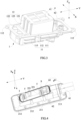
FIG. 1 is an exploded view of a multifunctional high-voltage connector according to the present invention. -
FIG. 2 is an assembled view ofFIG. 1 . -
FIG. 3 is a schematic view showing the mounting of a conductive connection structure and an upper cover of the multifunctional high-voltage connector. -
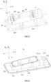
FIG. 4 is a schematic view showing the mounting of a mating terminal, a harness assembly and a pedestal of the multifunctional high-voltage connector. -
FIG. 5 is a schematic view showing the mounting of an inner base of the pedestal and the mating terminal ofFIG. 4 . -
FIG. 6 is a perspective view of an outer base of the pedestal. -
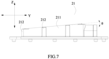
FIG. 7 is a front view ofFIG. 6 . -
- 1 upper cover
- 11 outer shell
- 111 first oblique-port portion
- 112 first connecting portion
- 113 guiding portion
- 12 inner shell
- 121 first guide portion
- 122 body portion
- 123 extending portion
- 11 outer shell
- 2 pedestal
- 21 outer base
- 211 second oblique-port portion
211A receiving groove - 212 second connecting portion
- 213 mounting portion
- 211 second oblique-port portion
- 22 inner base
- 221 second guide portion
- 222 bottom plate portion
- 223 protruding portion
- 21 outer base
- 3 sealing ring
- 4 conductive connection structure
- 41 main body portion
- 42 conductive connection portion
- 5 mating terminal
- 6 harness assembly
- 61 wire harness body
- 62 connection terminal
- S fastener
- X transversal direction
- Y longitudinal direction
- Z vertical direction
- To make the object, technical solutions, and advantages of the present invention more apparent, hereinafter the present invention will be further described in detail in combination with the accompanying figures and the embodiments. It should be understood that the specific embodiments described herein are merely used to explain the present invention but are not intended to limit the present invention.
- In the description of the present invention, unless otherwise specifically defined and limited, the terms "first", "second" and the like are only used for illustrative purposes and are not to be construed as expressing or implying a relative importance. The term "plurality" is two or more. Unless otherwise defined or described, the terms "connect", "fix" should be broadly interpreted, for example, the term "connect" can be "fixedly connect", "detachably connect", "integrally connect", "electrically connect" or "signal connect". The term "connect" also can be "directly connect" or "indirectly connect via a medium". For the persons skilled in the art, the specific meanings of the abovementioned terms in the present invention can be understood according to the specific situation.
- In the description of the present invention, it should be understood that spatially relative terms, such as "above", "below" "inside", "outside" and the like, are described based on orientations illustrated in the figures, but are not intended to limit the embodiments of the present invention.
- Referring to
FIG. 1 and FIG. 2 , a multifunctional high-voltage connector according to the present invention comprises anupper cover 1, apedestal 2, a sealingring 3, aconductive connection structure 4, twomating terminals 5 and aharness assembly 6. - The
upper cover 1 is detachably assembled with thepedestal 2. Referring toFIG. 3 , theupper cover 1 may comprise: anouter shell 11 having a first oblique-port portion 111; and aninner shell 12 fixed at an inner side of theouter shell 11 and provided with afirst guide portion 121. Referring toFIG. 4 to FIG. 6 , thepedestal 2 may comprise: anouter base 21 having a second oblique-port portion 211; and aninner base 22 fixed at an inner side of theouter base 21 and provided with asecond guide portion 221. Theouter shell 11 and theouter base 21 may be made of a metal material, and theinner shell 12 and theinner base 22 may be made of an insulating material. - When the
upper cover 1 is assembled with thepedestal 2, firstly thefirst guide portion 121 of theinner shell 12 and thesecond guide portion 221 of theinner base 22 cooperate (such as a concave-convex fit as described below) by a visual positioning, then theupper cover 1 can gradually approach thepedestal 2 along the cooperation direction of thefirst guide portion 121 and thesecond guide portion 221 until the first oblique-port portion 111 of theouter shell 11 cooperates (i.e., the first oblique-port portion 111 and the second oblique-port portion 211 abut against each other face to face) with the second oblique-port portion 211 of theouter base 21, and it means that theupper cover 1 is mounted in place. - Since the first oblique-
port portion 111 of theouter shell 11 is an oblique-port structure, which reduces the weight of theupper cover 1 and facilitates the mounting and detachment between theupper cover 1 and thepedestal 2; and at the same time, the cooperation between thefirst guide portion 121 of theinner shell 12 and thesecond guide portion 221 of theinner base 22 can provide a guide for the mounting between theupper cover 1 and thepedestal 2, and the cooperation between thefirst guide portion 121 and thesecond guide portion 221 can be reliably operated by the visual positioning, therefore it is not necessary to assemble many times and can ensure the accurate mounting between theupper cover 1 and thepedestal 2, and thus the multifunctional high-voltage connector according to the present invention greatly improves the assembling efficiency and assembling accuracy of the multifunctional high-voltage connector. In addition, since the second oblique-port portion 211 of thepedestal 2 may also be an oblique-port structure, the cooperation between the second oblique-port portion 211 and the first oblique-port portion 111 of theupper cover 1 reduces the internal space of the multifunctional high-voltage connector and improves the space utilization of the multifunctional high-voltage connector. - Referring to
FIG. 1 ,FIG. 4 andFIG. 6 , the second oblique-port portion 211 of theouter base 21 is provided with a receivinggroove 211A, and the receivinggroove 211A is used for receiving the sealingring 3. When theupper cover 1 and thepedestal 2 are assembled, the sealingring 3 is pressed in the receivinggroove 211A to seal theouter base 21 of thepedestal 2 and theouter shell 11 of theupper cover 1. - Referring to
FIG. 7 , an angle between the lower surface (i.e., the mounting surface) of the first oblique-port portion 111 and a longitudinal direction Y and an angle between the upper surface (i.e., the mounting surface) of the second oblique-port portion 211 and the longitudinal direction Y are both θ. Since the lighter the quality of theupper cover 1 is, the more it is helpful to improve the assembling efficiency and assembling accuracy of the multifunctional high-voltage connector, therefore in order to minimize the weight of theupper cover 1, the size of θ needs to be designed in a reasonable extent. After many designs and operations of mounting, the inventors found that when 5≤θ≤8, it is most beneficial to the mounting and detachment between theupper cover 1 and thepedestal 2. - The manner of cooperation between the
first guide portion 121 of theinner shell 12 and thesecond guide portion 221 of theinner base 22 may be a concave-convex fit. Specifically, thefirst guide portion 121 is a recessed groove (as shown inFIG. 3 ); correspondingly, thesecond guide portion 221 is a protrusion (as shown inFIG. 4 andFIG. 5 ). Alternatively, thefirst guide portion 121 is a protrusion; correspondingly, thesecond guide portion 221 is a recessed groove. - Referring to
FIG. 3 , theouter shell 11 may further comprise a first connectingportion 112 formed at an outer side of the first oblique-port portion 111 around a circumference of the first oblique-port portion 111 and extending in a vertical direction Z. Referring toFIG. 4 andFIG. 6 , theouter base 21 may further comprise a second connectingportion 212 formed at an outer side of the second oblique-port portion 211 around a circumference of the second oblique-port portion 211. - Both the first connecting
portion 112 and the second connectingportion 212 may be provided as multiple in number. The multiple first connectingportions 112 are spaced apart at the outer side of the first oblique-port portion 111 around the circumference of the first oblique-port portion 111, the multiple second connectingportion 212 are spaced apart at the outer side of the second oblique-port portion 211 around the circumference of the second oblique-port portion 211. - Referring to
FIG. 2 , each first connectingportion 112 may be connected to the corresponding second connectingportion 212 by a fastener S (such as a connecting bolt). In order to ensure that the locking force of the fastener S is not decomposed during the process of connecting, both a lower surface of the first connectingportion 112 and an upper surface of the second connectingportion 212 are parallel to the longitudinal direction Y. In other words, the lower surface of the first connectingportion 112 and the upper surface of the second connectingportion 212 are both planar. In order to increase the strength of theupper cover 1, referring toFIG. 1 to FIG. 3 , theouter shell 11 may comprise a guidingportion 113 formed at the outside of the first oblique-port portion 111 and protruding from the first oblique-port portion 111. It should be noted that, since the first oblique-port portion 111 is the oblique-port structure, if the guidingportion 113 extends in the vertical direction Z, it is easy to enlarge the mass difference between the two ends of theupper cover 1 in the longitudinal direction Y, which makes the center of gravity shifted and is not beneficial to the mounting and detachment between theupper cover 1 and thepedestal 2. Therefore, in order to facilitate the mounting and operation, the guidingportion 113 may be provided at both sides of theouter shell 11 in a transversal direction X and extending in a direction paralleled to the lower surface of the first oblique-port portion 111, that is, the guidingportion 113 extends obliquely relative to the longitudinal direction Y. - Referring to
FIG. 6 , theouter base 21 may further comprise a mountingportion 213 formed at an outer side of the second oblique-port portion 211 and extending in the longitudinal direction Y, and the mountingportion 213 mounts theharness assembly 6. In the process of assembling, in order not to interfere with the cooperation between the first oblique-port portion 111 and the second oblique-port portion 211, the highest point of the mounting surface of the second oblique-port portion 211 is higher than a top surface of the mountingportion 213. - Referring to
FIG. 3 , theinner shell 12 may further comprise: abody portion 122 accommodated in theouter shell 11; and an extendingportion 123 protruding from thebody portion 122 in the vertical direction Z and extending out of theouter shell 11. Thefirst guide portion 121 is provided on the extendingportion 123 and extends in the vertical direction Z, when theupper cover 1 is assembled with thepedestal 2, the extendingportion 123 of theinner shell 12 is inserted into theinner base 22 of thepedestal 2 to make thefirst guide portion 121 cooperate with thesecond guide portion 221. - The
first guide portion 121 is provided as multiple in number. In an embodiment, the multiplefirst guide portions 121 are provided on both sides of the extendingportion 123 in the longitudinal direction Y. In another embodiment, the multiplefirst guide portions 121 may be provided on both sides of the extendingportion 123 in the transversal direction X. In still another embodiment, the multiplefirst guide portions 121 are provided on both sides of the extendingportion 123 in the longitudinal direction Y and both sides of the extendingportion 123 in the transversal direction X at the same time. That thefirst guide portion 121 adopts the above arrangement manner makes the opposite sides of theupper cover 1 limited in position during the process of assembling, thereby further ensuring the accurate mounting between theupper cover 1 and thepedestal 2. - The
conductive connection structure 4 is fixedly mounted to theupper cover 1. Specifically, referring toFIG. 3 , theconductive connection structure 4 may comprise: amain body portion 41 accommodated in theinner shell 12 of theupper cover 1; and twoconductive connection portions 42 formed at both ends of themain body portion 41 in the longitudinal direction Y and extending out of theouter shell 11, and each of theconductive connection portions 42 is used for mating connection with one of themating terminals 5. Here, theconductive connection structure 4 may be a fuse or a one-piece structure (that is a whole piece of connection sheet). - Referring to
FIG. 4 andFIG. 5 , the twomating terminals 5 are spaced apart in the longitudinal direction Y, and each of themating terminals 5 is fixedly mounted to theinner base 22 of thepedestal 2. Here, themating terminal 5 has elasticity. When themating terminal 5 are mated with the correspondingconductive connection portion 42 of theconductive connection structure 4, themating terminal 5 can clamp theconductive connection portion 42, thereby ensuring the connection reliability between theconductive connection structure 4 and themating terminal 5 during the process of use. - Referring to
FIG. 5 , theinner base 22 may further comprise: abottom plate portion 222; and two protrudingportions 223 spaced apart in the longitudinal direction Y, each of the protrudingportions 223 protrudes from thebottom plate portion 222 in the vertical direction Z and mounts thecorresponding mating terminal 5. Thesecond guide portion 221 is provided on each of the protrudingportions 223. - When the
upper cover 1 is assembled with thepedestal 2, based on the cooperation between thefirst guide portion 121 of theinner shell 12 and thesecond guide portion 221 of theinner base 22, theconductive connection portion 42 of theconductive connection structure 4 can be accurately inserted into the corresponding protrudingportion 223 and mated with themating terminal 5 in the protrudingportion 223, thereby avoiding the ablation problem caused by the abrasion of themating terminal 5 due to multiple attempts. - Referring to
FIG. 4 , theharness assembly 6 is mounted to thepedestal 2 and connected to one mating terminal 5 (theother mating terminal 5 is exposed at the bottom of the pedestal 2). Specifically, theharness assembly 6 may comprise: awire harness body 61, one end of thewire harness body 61 is fixed to the mountingportion 213 of theouter base 21 and the other end of thewire harness body 61 protrudes from the mountingportion 213 in the longitudinal direction Y; and aconnection terminal 62 connected to the one end of thewire harness body 61 and the onemating terminal 5. - When the multifunctional high-voltage connector is applied to a battery product (such as a battery pack or a high voltage cartridge), the
other mating terminal 5 is connected to the battery inside the battery pack, theharness assembly 6 is connected to other devices (such as another battery pack or another high voltage cartridge) outside the battery pack), thereby achieving an electrical connection between the battery inside the battery product and the other devices.
Claims (9)
- A multifunctional high-voltage connector, comprising a pedestal (2) and an upper cover (1) detachably assembled with the pedestal (2);the upper cover (1) comprising: an outer shell (11) having a first oblique-port portion (111); and an inner shell (12) fixed at an inner side of the outer shell (11) and provided with a first guide portion (121);the pedestal (2) comprising: an outer base (21) having a second oblique-port portion (211); and an inner base (22) fixed at an inner side of the outer base (21) and provided with a second guide portion (221);the first oblique-port portion (111) of the outer shell (11) cooperating with the second oblique-port portion (211) of the outer base (21), and the first guide portion (121) of the inner shell (12) cooperating with the second guide portion (221) of the inner base (22);characterized in thatthe first guide portion (121) is a recessed groove, and the second guide portion (221) is a protrusion; or thefirst guide portion (121) is a protrusion, and the second guide portion (221) is a recessed groove;wherein theinner shell (12) further comprises: a body portion (122) accommodated in the outer shell (11); and an extending portion (123) protruding from the body portion (122) in a vertical direction (Z) and extending out of the outer shell (11);the first guide portion (121) is provided on the extending portion (123) and extends in the vertical direction (Z), and the extending portion (123) is inserted into the inner base (22) to make the first guide portion (121) cooperate with the second guide portion (221);the outer shell (11) further comprises: a guiding portion (113) formed at an outside of the first oblique-port portion (111) and extending in a direction paralleled to a lower surface of the first oblique-port portion (111).
- The multifunctional high-voltage connector according to claim 1, wherein an angle between a lower surface of the first oblique-port portion (111) and a longitudinal direction (Y) and an angle in Degrees
between an upper surface of the second oblique-port portion (211) and the longitudinal direction (Y) are both θ, and 5≤θ≤8. - The multifunctional high-voltage connector according to claim 1, whereinthe first guide portions (121) are provided on both sides of the extending portion (123) in a longitudinal direction (Y); or /andthe first guide portions (121) are provided on both sides of the extending portion (123) in a transversal direction (X).
- The multifunctional high-voltage connector according to claim 1, whereinthe outer shell (11) further comprises: a first connecting portion (112) formed at an outer side of the first oblique-port portion (111) around a circumference of the first oblique-port portion (111) and extending in a vertical direction (Z);the outer base (21) further comprises: a second connecting portion (212) formed at an outer side of the second oblique-port portion (211) around a circumference of the second oblique-port portion (211) and connecting the first connecting portion (112);a lower surface of the first connecting portion (112) and an upper surface of the second connecting portion (212) are parallel to a longitudinal direction (Y).
- The multifunctional high-voltage connector according to claim 1, whereinthe multifunctional high-voltage connector further comprises a conductive connection structure (4) and two mating terminals (5);the conductive connection structure (4) comprises: a main body portion (41) accommodated in the inner shell (12) of the upper cover (1); and two conductive connection portions (42) formed at both ends of the main body portion (41) in a longitudinal direction (Y) and extending out of the outer shell (11);the two mating terminals (5) are spaced apart in the longitudinal direction (Y), and each of the mating terminals (5) is fixedly mounted to the inner base (22) of the pedestal (2) and mates with a corresponding conductive connection portions (42).
- The multifunctional high-voltage connector according to claim 5, whereinthe inner base (22) further comprises: a bottom plate portion (222); and two protruding portions (223) spaced apart in the longitudinal direction (Y), and each of the protruding portions (223) protrudes from the bottom plate portion (222) in a vertical direction (Z) and mounts the corresponding mating terminal (5);the second guide portion (221) is provided on each of the protruding portions (223).
- The multifunctional high-voltage connector according to claim 5, whereinthe multifunctional high-voltage connector further comprises: a harness assembly (6) connected to one of the two mating terminals (5);the outer base (21) further comprises: a mounting portion (213) formed at an outer side of the second oblique-port portion (211) and extending in the longitudinal direction (Y), and the mounting portion (213) mounts the harness assembly (6);the highest point of an upper surface of the second oblique-port portion (211) is higher than a top surface of the mounting portion (213).
- The multifunctional high-voltage connector according to claim 1, wherein the outer shell (11) and the outer base (21) is made of a metal material, and the inner shell (12) and the inner base (22) is made of an insulating material.
- A battery product, comprising the multifunctional high-voltage connector according to any one of claims 1-8.
Applications Claiming Priority (1)
| Application Number | Priority Date | Filing Date | Title |
|---|---|---|---|
| CN201821835165.0U CN208955294U (en) | 2018-11-08 | 2018-11-08 | Multifunctional high pressure connector |
Publications (3)
| Publication Number | Publication Date |
|---|---|
| EP3651279A1 EP3651279A1 (en) | 2020-05-13 |
| EP3651279C0 EP3651279C0 (en) | 2025-02-12 |
| EP3651279B1 true EP3651279B1 (en) | 2025-02-12 |
Family
ID=66744232
Family Applications (1)
| Application Number | Title | Priority Date | Filing Date |
|---|---|---|---|
| EP19205293.4A Active EP3651279B1 (en) | 2018-11-08 | 2019-10-25 | Multifunctional high-voltage connector and battery product |
Country Status (5)
| Country | Link |
|---|---|
| US (1) | US10868388B2 (en) |
| EP (1) | EP3651279B1 (en) |
| JP (1) | JP6858236B2 (en) |
| CN (1) | CN208955294U (en) |
| WO (1) | WO2020093918A1 (en) |
Families Citing this family (5)
| Publication number | Priority date | Publication date | Assignee | Title |
|---|---|---|---|---|
| CN208955294U (en) | 2018-11-08 | 2019-06-07 | 宁德时代新能源科技股份有限公司 | Multifunctional high pressure connector |
| CN113659269B (en) * | 2020-04-29 | 2026-04-28 | 郑州深澜动力科技有限公司 | A battery box assembly and a battery |
| KR102496152B1 (en) * | 2020-09-10 | 2023-02-06 | 한국단자공업 주식회사 | Block structure |
| JP7384861B2 (en) * | 2021-06-28 | 2023-11-21 | 矢崎総業株式会社 | shield connector |
| US20250316825A1 (en) | 2024-04-09 | 2025-10-09 | Caterpillar Inc. | Electrical Connector for High Voltage Cables |
Citations (4)
| Publication number | Priority date | Publication date | Assignee | Title |
|---|---|---|---|---|
| JP2017045572A (en) * | 2015-08-25 | 2017-03-02 | 住友電装株式会社 | connector |
| CN206864727U (en) * | 2017-04-28 | 2018-01-09 | 惠州领先精密科技有限公司 | A kind of high voltage shielded electrical connector |
| EP3293404A1 (en) * | 2016-09-12 | 2018-03-14 | Newfrey LLC | Plastic cap and assembly including such a plastic cap |
| EP3154131B1 (en) * | 2015-10-06 | 2019-01-30 | Phihong Technology Co., Ltd. | Power plug device and the manufacturing method thereof |
Family Cites Families (15)
| Publication number | Priority date | Publication date | Assignee | Title |
|---|---|---|---|---|
| US6208233B1 (en) * | 2000-03-03 | 2001-03-27 | Delphi Technologies, Inc. | Trim resistor connector and sensor system |
| US8242874B2 (en) * | 2005-08-23 | 2012-08-14 | Lear Corporation | Electrical connector housing |
| EP2048746B1 (en) * | 2007-08-13 | 2016-10-05 | Tyco Electronics Nederland B.V. | Busbar connection system |
| CN202004021U (en) * | 2011-03-08 | 2011-10-05 | 莱尼电气线缆(常州)有限公司 | Solar junction box |
| US9099814B2 (en) * | 2013-07-16 | 2015-08-04 | Delphi Technologies, Inc. | Shielded electrical header assembly |
| US9831482B2 (en) * | 2013-09-06 | 2017-11-28 | Johnson Controls Technology Company | Battery module lid system and method |
| KR102210887B1 (en) * | 2016-08-01 | 2021-02-02 | 삼성에스디아이 주식회사 | Battery module |
| CN206210738U (en) * | 2016-11-30 | 2017-05-31 | 深圳市品川新能源连接器件有限公司 | A kind of Manual maintenance switch |
| CN207116791U (en) | 2017-08-17 | 2018-03-16 | 东莞能连电子科技有限公司 | One kind electromagnetic shielding high-tension connector |
| CN207819094U (en) * | 2018-01-31 | 2018-09-04 | 宁德时代新能源科技股份有限公司 | High voltage connector |
| CN207967540U (en) * | 2018-03-02 | 2018-10-12 | 宁德时代新能源科技股份有限公司 | Connector and connection component |
| CN208690572U (en) * | 2018-08-15 | 2019-04-02 | 宁德时代新能源科技股份有限公司 | Plug terminals, multifunctional high voltage connectors and battery products |
| CN208508146U (en) * | 2018-08-15 | 2019-02-15 | 宁德时代新能源科技股份有限公司 | Multifunctional high pressure connector and battery product |
| CN208690601U (en) * | 2018-08-15 | 2019-04-02 | 宁德时代新能源科技股份有限公司 | Conductive connection structure, multifunctional high voltage connector and battery products |
| CN208955294U (en) * | 2018-11-08 | 2019-06-07 | 宁德时代新能源科技股份有限公司 | Multifunctional high pressure connector |
-
2018
- 2018-11-08 CN CN201821835165.0U patent/CN208955294U/en active Active
-
2019
- 2019-10-25 EP EP19205293.4A patent/EP3651279B1/en active Active
- 2019-10-28 JP JP2019194979A patent/JP6858236B2/en active Active
- 2019-10-30 US US16/669,028 patent/US10868388B2/en active Active
- 2019-10-30 WO PCT/CN2019/114410 patent/WO2020093918A1/en not_active Ceased
Patent Citations (4)
| Publication number | Priority date | Publication date | Assignee | Title |
|---|---|---|---|---|
| JP2017045572A (en) * | 2015-08-25 | 2017-03-02 | 住友電装株式会社 | connector |
| EP3154131B1 (en) * | 2015-10-06 | 2019-01-30 | Phihong Technology Co., Ltd. | Power plug device and the manufacturing method thereof |
| EP3293404A1 (en) * | 2016-09-12 | 2018-03-14 | Newfrey LLC | Plastic cap and assembly including such a plastic cap |
| CN206864727U (en) * | 2017-04-28 | 2018-01-09 | 惠州领先精密科技有限公司 | A kind of high voltage shielded electrical connector |
Also Published As
| Publication number | Publication date |
|---|---|
| WO2020093918A1 (en) | 2020-05-14 |
| JP2020077629A (en) | 2020-05-21 |
| EP3651279A1 (en) | 2020-05-13 |
| CN208955294U (en) | 2019-06-07 |
| EP3651279C0 (en) | 2025-02-12 |
| JP6858236B2 (en) | 2021-04-14 |
| US10868388B2 (en) | 2020-12-15 |
| US20200153158A1 (en) | 2020-05-14 |
Similar Documents
| Publication | Publication Date | Title |
|---|---|---|
| EP3651279B1 (en) | Multifunctional high-voltage connector and battery product | |
| EP2619853B1 (en) | Terminal block structure | |
| US9281613B2 (en) | Battery wiring module | |
| US11990694B2 (en) | Multifunctional high-voltage connector and battery product | |
| EP3611802B1 (en) | Multifunctional high-voltage connector and battery product | |
| EP3611751B1 (en) | Conductive connection structure, multifunctional high-voltage connector and battery product | |
| US20200176916A1 (en) | Power connector device including improved terminal | |
| EP3896794A1 (en) | Connector | |
| WO2017073291A1 (en) | Terminal | |
| CN208189884U (en) | High-tension connector and vehicle with it | |
| CN218828159U (en) | Socket and connector | |
| CN218732105U (en) | Floating connector | |
| CN221041790U (en) | High-voltage shielding connector | |
| CN214957702U (en) | Connector with a locking member | |
| JP6915024B2 (en) | Battery products | |
| JP2018063784A (en) | Secondary battery | |
| CN219642970U (en) | Battery cover plate assembly and battery | |
| CN221961097U (en) | Battery cover plate and battery | |
| CN222915104U (en) | Top cover assembly and battery | |
| CN223771469U (en) | High-voltage connector for electric automobile | |
| CN223978245U (en) | A shielding structure for a high-voltage connector and the high-voltage connector itself. | |
| CN220527235U (en) | Electric connector assembly | |
| CN217062649U (en) | Industrial aviation socket | |
| CN218849880U (en) | Electric connector for seat type connection | |
| CN211106418U (en) | Printer and printing method |
Legal Events
| Date | Code | Title | Description |
|---|---|---|---|
| PUAI | Public reference made under article 153(3) epc to a published international application that has entered the european phase |
Free format text: ORIGINAL CODE: 0009012 |
|
| STAA | Information on the status of an ep patent application or granted ep patent |
Free format text: STATUS: REQUEST FOR EXAMINATION WAS MADE |
|
| 17P | Request for examination filed |
Effective date: 20191025 |
|
| AK | Designated contracting states |
Kind code of ref document: A1 Designated state(s): AL AT BE BG CH CY CZ DE DK EE ES FI FR GB GR HR HU IE IS IT LI LT LU LV MC MK MT NL NO PL PT RO RS SE SI SK SM TR |
|
| AX | Request for extension of the european patent |
Extension state: BA ME |
|
| STAA | Information on the status of an ep patent application or granted ep patent |
Free format text: STATUS: EXAMINATION IS IN PROGRESS |
|
| 17Q | First examination report despatched |
Effective date: 20201016 |
|
| REG | Reference to a national code |
Ref country code: DE Ref legal event code: R079 Free format text: PREVIOUS MAIN CLASS: H01R0013502000 Ipc: H01M0050202000 Ref country code: DE Ref legal event code: R079 Ref document number: 602019065704 Country of ref document: DE Free format text: PREVIOUS MAIN CLASS: H01R0013502000 Ipc: H01M0050202000 |
|
| RAP1 | Party data changed (applicant data changed or rights of an application transferred) |
Owner name: CONTEMPORARY AMPEREX TECHNOLOGY(HONG KONG) LIMITED |
|
| GRAP | Despatch of communication of intention to grant a patent |
Free format text: ORIGINAL CODE: EPIDOSNIGR1 |
|
| STAA | Information on the status of an ep patent application or granted ep patent |
Free format text: STATUS: GRANT OF PATENT IS INTENDED |
|
| RIC1 | Information provided on ipc code assigned before grant |
Ipc: H01M 50/244 20210101ALI20240927BHEP Ipc: H01R 13/52 20060101ALI20240927BHEP Ipc: H01R 13/502 20060101ALI20240927BHEP Ipc: H01M 50/50 20210101ALI20240927BHEP Ipc: H01M 50/271 20210101ALI20240927BHEP Ipc: H01M 50/262 20210101ALI20240927BHEP Ipc: H01M 50/296 20210101ALI20240927BHEP Ipc: H01M 50/224 20210101ALI20240927BHEP Ipc: H01M 50/202 20210101AFI20240927BHEP |
|
| INTG | Intention to grant announced |
Effective date: 20241030 |
|
| GRAS | Grant fee paid |
Free format text: ORIGINAL CODE: EPIDOSNIGR3 |
|
| GRAA | (expected) grant |
Free format text: ORIGINAL CODE: 0009210 |
|
| STAA | Information on the status of an ep patent application or granted ep patent |
Free format text: STATUS: THE PATENT HAS BEEN GRANTED |
|
| AK | Designated contracting states |
Kind code of ref document: B1 Designated state(s): AL AT BE BG CH CY CZ DE DK EE ES FI FR GB GR HR HU IE IS IT LI LT LU LV MC MK MT NL NO PL PT RO RS SE SI SK SM TR |
|
| REG | Reference to a national code |
Ref country code: GB Ref legal event code: FG4D |
|
| REG | Reference to a national code |
Ref country code: CH Ref legal event code: EP |
|
| REG | Reference to a national code |
Ref country code: DE Ref legal event code: R096 Ref document number: 602019065704 Country of ref document: DE |
|
| REG | Reference to a national code |
Ref country code: IE Ref legal event code: FG4D |
|
| U01 | Request for unitary effect filed |
Effective date: 20250305 |
|
| U07 | Unitary effect registered |
Designated state(s): AT BE BG DE DK EE FI FR IT LT LU LV MT NL PT RO SE SI Effective date: 20250313 |
|
| PG25 | Lapsed in a contracting state [announced via postgrant information from national office to epo] |
Ref country code: RS Free format text: LAPSE BECAUSE OF FAILURE TO SUBMIT A TRANSLATION OF THE DESCRIPTION OR TO PAY THE FEE WITHIN THE PRESCRIBED TIME-LIMIT Effective date: 20250512 |
|
| PG25 | Lapsed in a contracting state [announced via postgrant information from national office to epo] |
Ref country code: PL Free format text: LAPSE BECAUSE OF FAILURE TO SUBMIT A TRANSLATION OF THE DESCRIPTION OR TO PAY THE FEE WITHIN THE PRESCRIBED TIME-LIMIT Effective date: 20250212 |
|
| PG25 | Lapsed in a contracting state [announced via postgrant information from national office to epo] |
Ref country code: ES Free format text: LAPSE BECAUSE OF FAILURE TO SUBMIT A TRANSLATION OF THE DESCRIPTION OR TO PAY THE FEE WITHIN THE PRESCRIBED TIME-LIMIT Effective date: 20250212 |
|
| PG25 | Lapsed in a contracting state [announced via postgrant information from national office to epo] |
Ref country code: IS Free format text: LAPSE BECAUSE OF FAILURE TO SUBMIT A TRANSLATION OF THE DESCRIPTION OR TO PAY THE FEE WITHIN THE PRESCRIBED TIME-LIMIT Effective date: 20250612 Ref country code: NO Free format text: LAPSE BECAUSE OF FAILURE TO SUBMIT A TRANSLATION OF THE DESCRIPTION OR TO PAY THE FEE WITHIN THE PRESCRIBED TIME-LIMIT Effective date: 20250512 |
|
| PG25 | Lapsed in a contracting state [announced via postgrant information from national office to epo] |
Ref country code: HR Free format text: LAPSE BECAUSE OF FAILURE TO SUBMIT A TRANSLATION OF THE DESCRIPTION OR TO PAY THE FEE WITHIN THE PRESCRIBED TIME-LIMIT Effective date: 20250212 |
|
| PG25 | Lapsed in a contracting state [announced via postgrant information from national office to epo] |
Ref country code: GR Free format text: LAPSE BECAUSE OF FAILURE TO SUBMIT A TRANSLATION OF THE DESCRIPTION OR TO PAY THE FEE WITHIN THE PRESCRIBED TIME-LIMIT Effective date: 20250513 |
|
| PG25 | Lapsed in a contracting state [announced via postgrant information from national office to epo] |
Ref country code: SM Free format text: LAPSE BECAUSE OF FAILURE TO SUBMIT A TRANSLATION OF THE DESCRIPTION OR TO PAY THE FEE WITHIN THE PRESCRIBED TIME-LIMIT Effective date: 20250212 |
|
| PG25 | Lapsed in a contracting state [announced via postgrant information from national office to epo] |
Ref country code: CZ Free format text: LAPSE BECAUSE OF FAILURE TO SUBMIT A TRANSLATION OF THE DESCRIPTION OR TO PAY THE FEE WITHIN THE PRESCRIBED TIME-LIMIT Effective date: 20250212 |
|
| PG25 | Lapsed in a contracting state [announced via postgrant information from national office to epo] |
Ref country code: SK Free format text: LAPSE BECAUSE OF FAILURE TO SUBMIT A TRANSLATION OF THE DESCRIPTION OR TO PAY THE FEE WITHIN THE PRESCRIBED TIME-LIMIT Effective date: 20250212 |
|
| U20 | Renewal fee for the european patent with unitary effect paid |
Year of fee payment: 7 Effective date: 20251021 |
|
| PLBE | No opposition filed within time limit |
Free format text: ORIGINAL CODE: 0009261 |
|
| STAA | Information on the status of an ep patent application or granted ep patent |
Free format text: STATUS: NO OPPOSITION FILED WITHIN TIME LIMIT |
|
| PGFP | Annual fee paid to national office [announced via postgrant information from national office to epo] |
Ref country code: GB Payment date: 20251024 Year of fee payment: 7 |
|
| 26N | No opposition filed |
Effective date: 20251113 |