EP3651149A1 - Distortion imparting device and distortion imparting method - Google Patents
Distortion imparting device and distortion imparting method Download PDFInfo
- Publication number
- EP3651149A1 EP3651149A1 EP19207576.0A EP19207576A EP3651149A1 EP 3651149 A1 EP3651149 A1 EP 3651149A1 EP 19207576 A EP19207576 A EP 19207576A EP 3651149 A1 EP3651149 A1 EP 3651149A1
- Authority
- EP
- European Patent Office
- Prior art keywords
- voltage
- audio signal
- limiting
- amplification
- clip
- Prior art date
- Legal status (The legal status is an assumption and is not a legal conclusion. Google has not performed a legal analysis and makes no representation as to the accuracy of the status listed.)
- Granted
Links
Images



Classifications
-
- G—PHYSICS
- G10—MUSICAL INSTRUMENTS; ACOUSTICS
- G10H—ELECTROPHONIC MUSICAL INSTRUMENTS; INSTRUMENTS IN WHICH THE TONES ARE GENERATED BY ELECTROMECHANICAL MEANS OR ELECTRONIC GENERATORS, OR IN WHICH THE TONES ARE SYNTHESISED FROM A DATA STORE
- G10H3/00—Instruments in which the tones are generated by electromechanical means
- G10H3/12—Instruments in which the tones are generated by electromechanical means using mechanical resonant generators, e.g. strings or percussive instruments, the tones of which are picked up by electromechanical transducers, the electrical signals being further manipulated or amplified and subsequently converted to sound by a loudspeaker or equivalent instrument
- G10H3/14—Instruments in which the tones are generated by electromechanical means using mechanical resonant generators, e.g. strings or percussive instruments, the tones of which are picked up by electromechanical transducers, the electrical signals being further manipulated or amplified and subsequently converted to sound by a loudspeaker or equivalent instrument using mechanically actuated vibrators with pick-up means
- G10H3/18—Instruments in which the tones are generated by electromechanical means using mechanical resonant generators, e.g. strings or percussive instruments, the tones of which are picked up by electromechanical transducers, the electrical signals being further manipulated or amplified and subsequently converted to sound by a loudspeaker or equivalent instrument using mechanically actuated vibrators with pick-up means using a string, e.g. electric guitar
- G10H3/186—Means for processing the signal picked up from the strings
- G10H3/187—Means for processing the signal picked up from the strings for distorting the signal, e.g. to simulate tube amplifiers
-
- H—ELECTRICITY
- H03—ELECTRONIC CIRCUITRY
- H03G—CONTROL OF AMPLIFICATION
- H03G3/00—Gain control in amplifiers or frequency changers
- H03G3/20—Automatic control
- H03G3/30—Automatic control in amplifiers having semiconductor devices
- H03G3/3005—Automatic control in amplifiers having semiconductor devices in amplifiers suitable for low-frequencies, e.g. audio amplifiers
-
- G—PHYSICS
- G10—MUSICAL INSTRUMENTS; ACOUSTICS
- G10H—ELECTROPHONIC MUSICAL INSTRUMENTS; INSTRUMENTS IN WHICH THE TONES ARE GENERATED BY ELECTROMECHANICAL MEANS OR ELECTRONIC GENERATORS, OR IN WHICH THE TONES ARE SYNTHESISED FROM A DATA STORE
- G10H1/00—Details of electrophonic musical instruments
- G10H1/02—Means for controlling the tone frequencies, e.g. attack or decay; Means for producing special musical effects, e.g. vibratos or glissandos
- G10H1/06—Circuits for establishing the harmonic content of tones, or other arrangements for changing the tone colour
- G10H1/16—Circuits for establishing the harmonic content of tones, or other arrangements for changing the tone colour by non-linear elements
-
- H—ELECTRICITY
- H03—ELECTRONIC CIRCUITRY
- H03F—AMPLIFIERS
- H03F1/00—Details of amplifiers with only discharge tubes, only semiconductor devices or only unspecified devices as amplifying elements
- H03F1/08—Modifications of amplifiers to reduce detrimental influences of internal impedances of amplifying elements
- H03F1/12—Modifications of amplifiers to reduce detrimental influences of internal impedances of amplifying elements by use of attenuating means
-
- H—ELECTRICITY
- H03—ELECTRONIC CIRCUITRY
- H03F—AMPLIFIERS
- H03F3/00—Amplifiers with only discharge tubes or only semiconductor devices as amplifying elements
- H03F3/20—Power amplifiers, e.g. Class B amplifiers, Class C amplifiers
- H03F3/21—Power amplifiers, e.g. Class B amplifiers, Class C amplifiers with semiconductor devices only
- H03F3/211—Power amplifiers, e.g. Class B amplifiers, Class C amplifiers with semiconductor devices only using a combination of several amplifiers
-
- H—ELECTRICITY
- H03—ELECTRONIC CIRCUITRY
- H03G—CONTROL OF AMPLIFICATION
- H03G1/00—Details of arrangements for controlling amplification
- H03G1/0005—Circuits characterised by the type of controlling devices operated by a controlling current or voltage signal
- H03G1/0017—Circuits characterised by the type of controlling devices operated by a controlling current or voltage signal the device being at least one of the amplifying solid-state elements
-
- H—ELECTRICITY
- H04—ELECTRIC COMMUNICATION TECHNIQUE
- H04R—LOUDSPEAKERS, MICROPHONES, GRAMOPHONE PICK-UPS OR LIKE ACOUSTIC ELECTROMECHANICAL TRANSDUCERS; ELECTRIC HEARING AIDS; PUBLIC ADDRESS SYSTEMS
- H04R3/00—Circuits for transducers
-
- G—PHYSICS
- G10—MUSICAL INSTRUMENTS; ACOUSTICS
- G10H—ELECTROPHONIC MUSICAL INSTRUMENTS; INSTRUMENTS IN WHICH THE TONES ARE GENERATED BY ELECTROMECHANICAL MEANS OR ELECTRONIC GENERATORS, OR IN WHICH THE TONES ARE SYNTHESISED FROM A DATA STORE
- G10H2210/00—Aspects or methods of musical processing having intrinsic musical character, i.e. involving musical theory or musical parameters or relying on musical knowledge, as applied in electrophonic musical tools or instruments
- G10H2210/155—Musical effects
- G10H2210/311—Distortion, i.e. desired non-linear audio processing to change the tone colour, e.g. by adding harmonics or deliberately distorting the amplitude of an audio waveform
-
- H—ELECTRICITY
- H03—ELECTRONIC CIRCUITRY
- H03F—AMPLIFIERS
- H03F2200/00—Indexing scheme relating to amplifiers
- H03F2200/03—Indexing scheme relating to amplifiers the amplifier being designed for audio applications
-
- H—ELECTRICITY
- H03—ELECTRONIC CIRCUITRY
- H03G—CONTROL OF AMPLIFICATION
- H03G2201/00—Indexing scheme relating to subclass H03G
- H03G2201/10—Gain control characterised by the type of controlled element
- H03G2201/106—Gain control characterised by the type of controlled element being attenuating element
Definitions
- the disclosure relates to a device for providing a distortion effect to an audio signal.
- a solid state amplifier which can switch output levels.
- Such an amplifier can adjust an output level by attenuating an input signal of a power amplifier provided to the final stage.
- This function is called a power control function.
- it is necessary to add musical effects (e.g., distortion and the like) in a stage before a signal is input to the power amplifier.
- Patent Document 1 discloses a solid state amplifier capable of adding distortion as in a vacuum-tube amplifier by using a circuit which limits a voltage.
- Patent Document 1 Japanese Patent Laid-Open No. H08-065062
- the disclosure devised in view of the aforementioned circumstances provides a distortion imparting device capable of obtaining a natural distortion effect even though an output is decreased.
- a distortion imparting device of the disclosure includes: a first amplification part which attenuates an input audio signal on the basis of an attenuation factor set by a user and amplifies the attenuated audio signal; a second amplification part serially connected to the first amplification part; and a limiting part which is connected between an output terminal of the first amplification part and an input terminal of the second amplification part and limits an input voltage of the second amplification part to a predetermined clip voltage, wherein the limiting part determines the clip voltage on the basis of the attenuation factor.
- the first amplification part includes an amplifier which performs level control and the like on an input audio signal.
- the first amplification part may include a circuit which simulates effects of a vacuum-tube amplifier.
- the second amplification part includes an amplifier (power amplifier) which amplifies an input signal to a level suitable for driving a speaker.
- the first amplification part temporarily attenuates an input audio signal to a level based on an attenuation factor designated by a user and then amplifies the input audio signal.
- the limiting part is provided between the first amplification part and the second amplification part.
- the limiting part is a part which limits a voltage of an audio signal input to the second amplification part. That is, the limiting part performs an operation of clipping the voltage of the audio signal input to the second amplification part such that the voltage is equal to or less than a predetermined value.
- a voltage (clip voltage) limited by the limiting part is determined on the basis of an attenuation factor set by a user. Accordingly, an appropriate distortion effect can be obtained irrespective of settings of power control because a clip voltage depending on the attenuation factor set by the user is set.
- an attenuation factor may not necessarily be a value representing a magnification (percentage).
- the attenuation factor may be a value that designates a driving power of a speaker.
- the second amplification part may be a power amplifier, and the limiting part may acquire a power supply voltage of the second amplification part and determine the clip voltage additionally on the basis of the power supply voltage in addition to the attenuation factor.
- the second amplification part is a power amplifier
- the power supply voltage thereof may vary according to a load. Accordingly, a more natural distortion effect can be obtained by causing the clip voltage to follow the power supply voltage of the power amplifier in real time.
- the first amplification part may simulate characteristics of a predetermined vacuum tube designated by the user, and the limiting part may correct the clip voltage additionally on the basis of the characteristics of the vacuum tube designated by the user.
- an offset may be added to the clip voltage on the basis of the characteristics of the vacuum tube that is a simulation target. Accordingly, it is possible to reproduce differences in head margins (margins between a defined maximum level and actual generation of distortion) of each of vacuum tubes.
- the limiting part may set a voltage obtained by dividing the power supply voltage of the second amplification part by a predetermined ratio based on the attenuation factor as the clip voltage.
- a value obtained by associating the power supply voltage of the second amplification part with the attenuation factor can be set as the clip voltage.
- a distortion imparting method performed by a distortion imparting device which provides a distortion effect to an audio signal, includes: an attenuation step of attenuating an input audio signal on the basis of an attenuation factor set by a user; a first amplification step of amplifying the attenuated audio signal; a limiting step of limiting a voltage of the audio signal amplified in the first amplification step to a clip voltage; and a second amplification step of amplifying the limited audio signal, wherein the clip voltage is determined on the basis of the attenuation factor in the limiting step.
- the disclosure can be identified as a distortion imparting device including at least a part of the aforementioned parts.
- the disclosure can also be identified as a distortion imparting method performed by the distortion imparting device.
- the aforementioned processes and parts can be freely combined and implemented within a range in which technical inconsistency does not occur.
- An effect providing device is a device (distortion imparting device) which provides a sound effect (distortion effect) to an input audio signal, amplifies the audio signal and outputs the amplified audio signal.
- a configuration of the effect providing device 10 according to the embodiment will be described with reference to FIG. 1 .
- the audio input terminal 101 is a terminal through which an audio signal is input.
- an audio signal converted into an analog signal is input to the audio input terminal 101.
- the input audio signal is amplified through the preamplifier 103 and the power amplifier 105 and is output from the audio output terminal 109.
- the attenuator 102 attenuates the level of an input audio signal according to conditions designated by the operator 106 (which will be described later). For example, a user designates an attenuation factor in accordance with a play environment such as a studio, a stage or a house and the level of an audio signal is attenuated in response to the attenuation factor (also referred to as power control).
- a user designates an attenuation factor in accordance with a play environment such as a studio, a stage or a house and the level of an audio signal is attenuated in response to the attenuation factor (also referred to as power control).
- the preamplifier 103 is a circuit which performs adjustment and amplification on an input audio signal. Level adjustment, equalizing, balance adjustment and the like of an audio signal can be performed through the preamplifier 103. Meanwhile, the preamplifier 103 may simulate a specific vacuum tube.
- the attenuator 102 and the preamplifier 103 are exemplarily regarded as a first amplification part. Meanwhile, although the attenuator 102 and the preamplifier 103 are independent from each other in the embodiment, the function of the attenuator 102 may be integrated into the preamplifier 103.
- the limiting circuit 104 limits the voltage of an audio signal input to the power amplifier 105. Specifically, when the level of the audio signal reaches a threshold value of a voltage set in the limiting circuit 104, a signal level at the input terminal of the power amplifier 105 is suppressed. In other words, the level of an audio signal output from the preamplifier 103 and input to the power amplifier 105 is clipped (limited) by the limiting circuit 104. Accordingly, it is possible to simulate the overdrive effect of a vacuum-tube amplifier.
- the threshold value of the voltage used by the limiting circuit 104 is determined on the basis of a voltage determined by the clip voltage determination part 107 which will be described later. A method for determining the voltage will be described in detail later.
- the power amplifier 105 is an audio amplifier (power amplifier) which amplifies an input audio signal to a level suitable to drive a speaker and outputs the amplified audio signal.
- the power amplifier 105 is exemplarily regarded as a second amplification part, and the limiting circuit 104 is serially connected between the output terminal of the preamplifier 103 and the input terminal of the power amplifier 105.
- the operator 106 is an interface which designates an attenuation factor of an audio level.
- the operator 106 can designate and select any attenuation factor through a push button switch or the like.
- the clip voltage determination part 107 is a circuit which determines a reference value (clip voltage) of a voltage when the limiting circuit 104 limits an input signal.
- the limiting circuit 104 is a circuit which generates the overdrive effect of a vacuum-tube amplifier, as described above.
- the limiting circuit 104 and the clip voltage determination part 107 are exemplarily regarded as a limiting part.
- the effect providing device 10 can change the power control, that is, select an attenuation factor of an input signal.
- a clip voltage is caused to follow power control to be dynamically changed. Accordingly, distortion can be generated at the same point in input audio even when power control (that is, an attenuation factor of an input signal) is changed.
- the clip voltage determination part 107 determines a clip voltage on the basis of both of (1) power control designated by a user and (2) a power supply voltage supplied to the power amplifier 105. According to this configuration, it is possible to obtain the same tone change effect irrespective of designation of power control. Further, it is possible to reproduce distortion effect change caused by load variation in the power supply.
- the clip voltage in the description is a reference value and the limiting circuit 104 uses a value corrected on the basis of the clip voltage as an actual voltage limiting value. Details will be described later.
- the power supply circuit 108 is a circuit which supplies power for driving the power amplifier 105.
- the power supply circuit 108 may supply power for driving components other than the power amplifier 105.
- the audio output terminal 109 is an interface which outputs an amplified audio signal.
- FIG. 2 illustrates a modified example of the effect providing device 10 according to the embodiment.
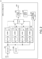
- FIG. 2 illustrates an example when four types A to D of combinations of the preamplifier 103 (shown as 103A to 103D) and the limiting circuit 104 (shown as 104A to 104D) (hereinafter referred to as preamplifier units) are provided.
- preamplifier units the preamplifier units
- FIG. 3 is a circuit diagram of the clip voltage determination part 107.
- the circuit of FIG. 3 generates a positive voltage as a clip voltage, a negative voltage is also generated using the same circuit.
- the positive voltage and the negative voltage have the same absolute value.
- Vpp is a power supply voltage for driving the power amplifier 105.
- Vpp can be acquired from the power supply circuit 108.
- Avcc is a stabilized power supply voltage for driving the preamplifier 103.
- GND is a reference voltage.
- a voltage is applied to any of POW_A, POW_B and POW C. If combined resistances according to Ra1 to Ra3 can be switched between, voltage application patterns are not limited to three types.
- V1 Vpp Rp / Ra 1 + Rp
- V 3 V 2 R 1 / Re
- V 3 Vpp ⁇ R 1 Rp / Ra 1 + Rp )
- the voltage V3 is a voltage obtained by dividing the power supply voltage supplied to the power amplifier by a ratio according to designation of power control.
- Vclp is a voltage obtained when the voltage V3 is buffered.
- a clip voltage ( ⁇ Vclp) depending on the power control and the power supply voltage (driving voltage) of the power amplifier 105 is generated through the above-described circuit.
- the generated clip voltage ( ⁇ Vclp) is input to the limiting circuit 104.
- the limiting circuit 104 will be described in detail with reference to FIG. 4 .
- An audio signal output from the preamplifier 103 is input to IN in the figure.
- the limiting circuit 104 includes a diode clipper and limits an input signal in response to an applied voltage (i.e., the clip voltage ⁇ Vclp generated by the clip voltage determination part 107). Accordingly, waveforms after clipping which have followed the input clip voltage are output.
- an amplifier 104-1 which amplifies an audio signal before clipping is provided before the diode clipper and an attenuator 104-2 which attenuates an audio signal after clipping is provided after the diode clipper.
- an offset to the clip voltage in response to an amplification factor of the amplifier 104-1 and an attenuation factor of the attenuator 104-2.
- the amplification factor and the attenuation factor have values suitable for a vacuum tube that is a simulation target. For example, in the case of the example of FIG. 2 , the amplification factor and the attenuation factor are combined differently for each of the limiting circuits 104A to 104D.
- the effect providing device clips an audio signal input to a power amplifier using a clip voltage generated on the basis of both power control designated by a user and a power supply voltage supplied to the power amplifier. According to such a configuration, it is possible to obtain the same tone change effect irrespective of details of designation of power control. Furthermore, it is possible to provide a nuance when power supply load varies. Accordingly, it is possible to reproduce dynamic change of distorted sound during overdrive of a vacuum-tube amplifier.
- preamplifiers for example, although a case in which one or four preamplifiers are provided is exemplified in description of the embodiment, a number of preamplifiers other than the exemplified number may be switched between.
Landscapes
- Engineering & Computer Science (AREA)
- Physics & Mathematics (AREA)
- Acoustics & Sound (AREA)
- Multimedia (AREA)
- Power Engineering (AREA)
- Signal Processing (AREA)
- Nonlinear Science (AREA)
- Amplifiers (AREA)
- Circuit For Audible Band Transducer (AREA)
- Electrophonic Musical Instruments (AREA)
Abstract
Description
- The disclosure relates to a device for providing a distortion effect to an audio signal.
- In the music field, a solid state amplifier which can switch output levels is known. Such an amplifier can adjust an output level by attenuating an input signal of a power amplifier provided to the final stage. This function is called a power control function. In this method, it is necessary to add musical effects (e.g., distortion and the like) in a stage before a signal is input to the power amplifier.
- On the other hand, even in a solid state amplifier, there is a demand for acquisition of distorted tones as in a vacuum-tube amplifier. The vacuum-tube amplifier can obtain a distinctive overdrive effect by being driven at high output. However, a solid state amplifier cannot obtain the overdrive effect even when a drive voltage is increased unlike the vacuum-tube amplifier. As a technology related to this, Patent Document 1 discloses a solid state amplifier capable of adding distortion as in a vacuum-tube amplifier by using a circuit which limits a voltage.
- [Patent Document 1] Japanese Patent Laid-Open No.
H08-065062 - However, in the amplifier disclosed in Patent Document 1, it is impossible to maintain distortion when the level of an input signal is decreased because a limit value of the voltage limiting circuit is constant. Although it is desirable that a guitar amplifier be able to set a plurality of attenuation factors in accordance with performance scenes such as studios and stages, the same distortion effect irrespective of output levels cannot be obtained in the conventional technology.
- The disclosure devised in view of the aforementioned circumstances provides a distortion imparting device capable of obtaining a natural distortion effect even though an output is decreased.
- To solve the aforementioned problem, a distortion imparting device of the disclosure includes: a first amplification part which attenuates an input audio signal on the basis of an attenuation factor set by a user and amplifies the attenuated audio signal; a second amplification part serially connected to the first amplification part; and a limiting part which is connected between an output terminal of the first amplification part and an input terminal of the second amplification part and limits an input voltage of the second amplification part to a predetermined clip voltage, wherein the limiting part determines the clip voltage on the basis of the attenuation factor.
- The first amplification part includes an amplifier which performs level control and the like on an input audio signal. The first amplification part may include a circuit which simulates effects of a vacuum-tube amplifier. The second amplification part includes an amplifier (power amplifier) which amplifies an input signal to a level suitable for driving a speaker. The first amplification part temporarily attenuates an input audio signal to a level based on an attenuation factor designated by a user and then amplifies the input audio signal.
- In addition, the limiting part is provided between the first amplification part and the second amplification part. The limiting part is a part which limits a voltage of an audio signal input to the second amplification part. That is, the limiting part performs an operation of clipping the voltage of the audio signal input to the second amplification part such that the voltage is equal to or less than a predetermined value.
- In the disclosure, a voltage (clip voltage) limited by the limiting part is determined on the basis of an attenuation factor set by a user. Accordingly, an appropriate distortion effect can be obtained irrespective of settings of power control because a clip voltage depending on the attenuation factor set by the user is set.
- Further, an attenuation factor may not necessarily be a value representing a magnification (percentage). For example, the attenuation factor may be a value that designates a driving power of a speaker.
- Further, the second amplification part may be a power amplifier, and the limiting part may acquire a power supply voltage of the second amplification part and determine the clip voltage additionally on the basis of the power supply voltage in addition to the attenuation factor.
- Since the second amplification part is a power amplifier, the power supply voltage thereof may vary according to a load. Accordingly, a more natural distortion effect can be obtained by causing the clip voltage to follow the power supply voltage of the power amplifier in real time.
- In addition, the first amplification part may simulate characteristics of a predetermined vacuum tube designated by the user, and the limiting part may correct the clip voltage additionally on the basis of the characteristics of the vacuum tube designated by the user.
- For example, an offset may be added to the clip voltage on the basis of the characteristics of the vacuum tube that is a simulation target. Accordingly, it is possible to reproduce differences in head margins (margins between a defined maximum level and actual generation of distortion) of each of vacuum tubes.
- In addition, the limiting part may set a voltage obtained by dividing the power supply voltage of the second amplification part by a predetermined ratio based on the attenuation factor as the clip voltage.
- According to such a configuration, a value obtained by associating the power supply voltage of the second amplification part with the attenuation factor can be set as the clip voltage.
- In addition, a distortion imparting method according to the disclosure, performed by a distortion imparting device which provides a distortion effect to an audio signal, includes: an attenuation step of attenuating an input audio signal on the basis of an attenuation factor set by a user; a first amplification step of amplifying the attenuated audio signal; a limiting step of limiting a voltage of the audio signal amplified in the first amplification step to a clip voltage; and a second amplification step of amplifying the limited audio signal, wherein the clip voltage is determined on the basis of the attenuation factor in the limiting step.
- The disclosure can be identified as a distortion imparting device including at least a part of the aforementioned parts. In addition, the disclosure can also be identified as a distortion imparting method performed by the distortion imparting device. The aforementioned processes and parts can be freely combined and implemented within a range in which technical inconsistency does not occur.
-
-
FIG. 1 is a configuration diagram of aneffect providing device 10 according to a first embodiment. -
FIG. 2 is a configuration diagram of aneffect providing device 10 according to a modified example of the first embodiment. -
FIG. 3 is a diagram for describing a circuit of a clip voltage determination part. -
FIG. 4 is a diagram for describing a limiting circuit. - Hereinafter, a preferred embodiment will be described with reference to the drawings. However, an embodiment described below can be appropriately modified according to system configurations and various conditions and is not limited to the illustrated form.
- An effect providing device according to a first embodiment is a device (distortion imparting device) which provides a sound effect (distortion effect) to an input audio signal, amplifies the audio signal and outputs the amplified audio signal.
- A configuration of the
effect providing device 10 according to the embodiment will be described with reference toFIG. 1 . - The
effect providing device 10 includes anaudio input terminal 101, anattenuator 102, apreamplifier 103, alimiting circuit 104, apower amplifier 105, anoperator 106, a clipvoltage determination part 107, apower supply circuit 108, and anaudio output terminal 109. - The
audio input terminal 101 is a terminal through which an audio signal is input. In the embodiment, an audio signal converted into an analog signal is input to theaudio input terminal 101. The input audio signal is amplified through thepreamplifier 103 and thepower amplifier 105 and is output from theaudio output terminal 109. - The
attenuator 102 attenuates the level of an input audio signal according to conditions designated by the operator 106 (which will be described later). For example, a user designates an attenuation factor in accordance with a play environment such as a studio, a stage or a house and the level of an audio signal is attenuated in response to the attenuation factor (also referred to as power control). - The
preamplifier 103 is a circuit which performs adjustment and amplification on an input audio signal. Level adjustment, equalizing, balance adjustment and the like of an audio signal can be performed through thepreamplifier 103. Meanwhile, thepreamplifier 103 may simulate a specific vacuum tube. - The
attenuator 102 and thepreamplifier 103 are exemplarily regarded as a first amplification part. Meanwhile, although theattenuator 102 and thepreamplifier 103 are independent from each other in the embodiment, the function of theattenuator 102 may be integrated into thepreamplifier 103. - The
limiting circuit 104 limits the voltage of an audio signal input to thepower amplifier 105. Specifically, when the level of the audio signal reaches a threshold value of a voltage set in the limitingcircuit 104, a signal level at the input terminal of thepower amplifier 105 is suppressed. In other words, the level of an audio signal output from thepreamplifier 103 and input to thepower amplifier 105 is clipped (limited) by the limitingcircuit 104. Accordingly, it is possible to simulate the overdrive effect of a vacuum-tube amplifier. The threshold value of the voltage used by the limitingcircuit 104 is determined on the basis of a voltage determined by the clipvoltage determination part 107 which will be described later. A method for determining the voltage will be described in detail later. - The
power amplifier 105 is an audio amplifier (power amplifier) which amplifies an input audio signal to a level suitable to drive a speaker and outputs the amplified audio signal. Thepower amplifier 105 is exemplarily regarded as a second amplification part, and the limitingcircuit 104 is serially connected between the output terminal of thepreamplifier 103 and the input terminal of thepower amplifier 105. - The
operator 106 is an interface which designates an attenuation factor of an audio level. For example, theoperator 106 can designate and select any attenuation factor through a push button switch or the like. - The clip
voltage determination part 107 is a circuit which determines a reference value (clip voltage) of a voltage when the limitingcircuit 104 limits an input signal. The limitingcircuit 104 is a circuit which generates the overdrive effect of a vacuum-tube amplifier, as described above. The limitingcircuit 104 and the clipvoltage determination part 107 are exemplarily regarded as a limiting part. - The
effect providing device 10 according to the embodiment can change the power control, that is, select an attenuation factor of an input signal. In the embodiment, a clip voltage is caused to follow power control to be dynamically changed. Accordingly, distortion can be generated at the same point in input audio even when power control (that is, an attenuation factor of an input signal) is changed. - However, when an input signal is amplified to a high power suitable for speaker output through a power amplifier, a voltage supplied to the power amplifier varies according to variation in a load applied to a power supply. Here, in order to obtain special effects of the vacuum-tube amplifier in which an appearance of distortion effect changes according to voltage variation, it is desirable to cause the clip voltage to follow a power supply voltage supplied to the power amplifier.
- In the embodiment, the clip
voltage determination part 107 determines a clip voltage on the basis of both of (1) power control designated by a user and (2) a power supply voltage supplied to thepower amplifier 105. According to this configuration, it is possible to obtain the same tone change effect irrespective of designation of power control. Further, it is possible to reproduce distortion effect change caused by load variation in the power supply. - Meanwhile, the clip voltage in the description is a reference value and the limiting
circuit 104 uses a value corrected on the basis of the clip voltage as an actual voltage limiting value. Details will be described later. - The
power supply circuit 108 is a circuit which supplies power for driving thepower amplifier 105. Thepower supply circuit 108 may supply power for driving components other than thepower amplifier 105. - The
audio output terminal 109 is an interface which outputs an amplified audio signal. -
FIG. 2 illustrates a modified example of theeffect providing device 10 according to the embodiment.FIG. 2 illustrates an example when four types A to D of combinations of the preamplifier 103 (shown as 103A to 103D) and the limiting circuit 104 (shown as 104A to 104D) (hereinafter referred to as preamplifier units) are provided. According to such a form, it is possible to switch between vacuum tubes that are simulation targets from a plurality of types (four types in the case of this example). Switching of preamplifier units can be performed through a second operator (selector 110) provided in the device. - Next, the clip
voltage determination part 107 will be described in detail with reference toFIG. 3. FIG. 3 is a circuit diagram of the clipvoltage determination part 107. Although the circuit ofFIG. 3 generates a positive voltage as a clip voltage, a negative voltage is also generated using the same circuit. The positive voltage and the negative voltage have the same absolute value. - In the figure, Vpp is a power supply voltage for driving the
power amplifier 105. Vpp can be acquired from thepower supply circuit 108. Avcc is a stabilized power supply voltage for driving thepreamplifier 103. In addition, GND is a reference voltage. - When a user operates the
operator 106 to designate power control, a voltage is applied to any of POW_A, POW_B and POW C. If combined resistances according to Ra1 to Ra3 can be switched between, voltage application patterns are not limited to three types. - Here, when it is assumed that the voltage is applied only to POW_A, a voltage applied to V1 is represented by expression (1). That is, the voltage V1 is a voltage obtained by dividing the power supply voltage Vpp of the power amplifier by Rp/(Ra1+Rp) that is a ratio according to designation of power control.

- In addition, a voltage applied to V3 is represented by expression (2) because the emitter current and the base current of a transistor Tr1 are almost the same.

- Here, expression (3) is established when it is assumed that V1≒V2.

- That is, it is ascertained that the voltage V3 is a voltage obtained by dividing the power supply voltage supplied to the power amplifier by a ratio according to designation of power control. Vclp is a voltage obtained when the voltage V3 is buffered.
- A clip voltage (±Vclp) depending on the power control and the power supply voltage (driving voltage) of the
power amplifier 105 is generated through the above-described circuit. The generated clip voltage (±Vclp) is input to the limitingcircuit 104. - Next, the limiting
circuit 104 will be described in detail with reference toFIG. 4 . An audio signal output from thepreamplifier 103 is input to IN in the figure. The limitingcircuit 104 according to the embodiment includes a diode clipper and limits an input signal in response to an applied voltage (i.e., the clip voltage ±Vclp generated by the clip voltage determination part 107). Accordingly, waveforms after clipping which have followed the input clip voltage are output. - Further, in the limiting
circuit 104 according to the embodiment, an amplifier 104-1 which amplifies an audio signal before clipping is provided before the diode clipper and an attenuator 104-2 which attenuates an audio signal after clipping is provided after the diode clipper. According to such a configuration, it is possible to add an offset to the clip voltage in response to an amplification factor of the amplifier 104-1 and an attenuation factor of the attenuator 104-2. Accordingly, it is possible to add differences in the head margins of simulated vacuum tubes. It is desirable that the amplification factor and the attenuation factor have values suitable for a vacuum tube that is a simulation target. For example, in the case of the example ofFIG. 2 , the amplification factor and the attenuation factor are combined differently for each of the limitingcircuits 104A to 104D. - As described above, the effect providing device according to the first embodiment clips an audio signal input to a power amplifier using a clip voltage generated on the basis of both power control designated by a user and a power supply voltage supplied to the power amplifier. According to such a configuration, it is possible to obtain the same tone change effect irrespective of details of designation of power control. Furthermore, it is possible to provide a nuance when power supply load varies. Accordingly, it is possible to reproduce dynamic change of distorted sound during overdrive of a vacuum-tube amplifier.
- The above-described embodiment is merely an example and the disclosure can be appropriately modified and implemented without departing from the scope of the disclosure.
- For example, although a case in which one or four preamplifiers are provided is exemplified in description of the embodiment, a number of preamplifiers other than the exemplified number may be switched between.
-
- 10 Effect providing device
- 101 Audio input terminal
- 102 Attenuator
- 103 Preamplifier
- 104 Limiting circuit
- 105 Power amplifier
- 106 Operator
- 107 Clip voltage determination part
- 108 Power supply circuit
- 109 Audio output terminal
- 110 Selector
Claims (12)
- A distortion imparting device (10) characterized in that comprising:a first amplification part (102, 103) which attenuates an input audio signal on the basis of an attenuation factor set by a user and amplifies the attenuated audio signal;a second amplification part (105) serially connected to the first amplification part (102, 103); anda limiting part (104, 107) which is connected between an output terminal of the first amplification part (102, 103) and an input terminal of the second amplification part (105) and limits an input voltage of the second amplification part (105) to a clip voltage that is predetermined,wherein the limiting part (104, 107) determines the clip voltage on the basis of the attenuation factor.
- The distortion imparting device (10) according to claim 1, wherein the second amplification part (105) is a power amplifier, and the limiting part (104, 107) acquires a power supply voltage of the second amplification part (105) and determines the clip voltage additionally on the basis of the power supply voltage in addition to the attenuation factor.
- The distortion imparting device (10) according to claim 2, wherein the first amplification part (102, 103) simulates characteristics of a predetermined vacuum tube designated by the user, and the limiting part (104, 107) corrects the clip voltage additionally on the basis of the characteristics of the predetermined vacuum tube designated by the user.
- The distortion imparting device (10) according to claim 2 or 3, wherein the limiting part (104, 107) sets a voltage obtained by dividing the power supply voltage of the second amplification part (105) by a predetermined ratio based on the attenuation factor as the clip voltage.
- The distortion imparting device (10) according to claim 1, wherein the clip voltage is a reference value and the limiting part (104, 107) sets a value corrected on the basis of the clip voltage as an actual voltage limiting value.
- The distortion imparting device (10) according to claim 1, wherein the limiting part (104, 107) dynamically changes the clip voltage by causing the clip voltage to follow an attenuation factor of an input audio signal.
- A distortion imparting method performed by a distortion imparting device (10) which provides a distortion effect to an audio signal, the distortion imparting method characterized in that comprising:an attenuation step of attenuating an input audio signal on the basis of an attenuation factor set by a user;a first amplification step of amplifying the attenuated audio signal;a limiting step of limiting a voltage of the audio signal amplified in the first amplification step to a clip voltage; anda second amplification step of amplifying the limited audio signal,wherein the clip voltage is determined on the basis of the attenuation factor in the limiting step.
- The distortion imparting method according to claim 7, wherein a power supply voltage for amplifying the limited audio signal is acquired and the clip voltage is determined additionally on the basis of the power supply voltage in addition to the attenuation factor in the second amplification step.
- The distortion imparting method according to claim 8, wherein characteristics of a predetermined vacuum tube designated by the user are simulated in the second amplification step, and the clip voltage is corrected additionally on the basis of the characteristics of the predetermined vacuum tube designated by the user in the limiting step.
- The distortion imparting method according to claim 8 or 9, wherein a voltage obtained by dividing the power supply voltage for amplifying the limited audio signal by a predetermined ratio based on the attenuation factor is set as the clip voltage in the limiting step.
- The distortion imparting method according to claim 7, wherein the clip voltage is a reference value, and a value corrected on the basis of the clip voltage is set as an actual voltage limiting value in the limiting step.
- The distortion imparting method according to claim 7, wherein the clip voltage is dynamically changed by being caused to follow an attenuation factor of an input audio signal in the limiting step.
Applications Claiming Priority (1)
| Application Number | Priority Date | Filing Date | Title |
|---|---|---|---|
| JP2018211790A JP2020076928A (en) | 2018-11-09 | 2018-11-09 | Strain imparting device and strain imparting method |
Publications (2)
| Publication Number | Publication Date |
|---|---|
| EP3651149A1 true EP3651149A1 (en) | 2020-05-13 |
| EP3651149B1 EP3651149B1 (en) | 2022-01-05 |
Family
ID=68502826
Family Applications (1)
| Application Number | Title | Priority Date | Filing Date |
|---|---|---|---|
| EP19207576.0A Active EP3651149B1 (en) | 2018-11-09 | 2019-11-07 | Distortion imparting device and distortion imparting method |
Country Status (3)
| Country | Link |
|---|---|
| US (1) | US11233491B2 (en) |
| EP (1) | EP3651149B1 (en) |
| JP (1) | JP2020076928A (en) |
Families Citing this family (2)
| Publication number | Priority date | Publication date | Assignee | Title |
|---|---|---|---|---|
| WO2021215328A1 (en) | 2020-04-23 | 2021-10-28 | 富士フイルム株式会社 | Micromirror device |
| US12682874B2 (en) | 2022-03-24 | 2026-07-14 | Yamaha Corporation | Sound processing device and method of outputting parameter of sound processing device |
Citations (5)
| Publication number | Priority date | Publication date | Assignee | Title |
|---|---|---|---|---|
| GB2103004A (en) * | 1981-05-29 | 1983-02-09 | Peavey Electronics Corp | Circuit for distorting an audio signal |
| WO1988007787A1 (en) * | 1987-03-23 | 1988-10-06 | Pritchard Eric K | Semiconductor emulation of tube amplifiers |
| JPH0865062A (en) | 1994-07-15 | 1996-03-08 | Peavey Electron Corp | Power amplifier with clipping level control |
| WO2003077232A1 (en) * | 2002-03-12 | 2003-09-18 | Hiroshi Saitoh | Music signal distortion generation apparatus |
| US20130136278A1 (en) * | 2011-11-29 | 2013-05-30 | Quilter Labs, LLC | Guitar amplifier |
Family Cites Families (1)
| Publication number | Priority date | Publication date | Assignee | Title |
|---|---|---|---|---|
| ES2319955B2 (en) * | 2008-12-02 | 2009-09-22 | Universidad Politecnica De Madrid | PROCEDURE FOR AMPLIFICATION OF AUDIO SIGNS GENERATED BY MUSICAL INSTRUMENTS FOR SOLID STATE PREAMPLIFIERS. |
-
2018
- 2018-11-09 JP JP2018211790A patent/JP2020076928A/en active Pending
-
2019
- 2019-11-07 EP EP19207576.0A patent/EP3651149B1/en active Active
- 2019-11-07 US US16/677,586 patent/US11233491B2/en active Active
Patent Citations (5)
| Publication number | Priority date | Publication date | Assignee | Title |
|---|---|---|---|---|
| GB2103004A (en) * | 1981-05-29 | 1983-02-09 | Peavey Electronics Corp | Circuit for distorting an audio signal |
| WO1988007787A1 (en) * | 1987-03-23 | 1988-10-06 | Pritchard Eric K | Semiconductor emulation of tube amplifiers |
| JPH0865062A (en) | 1994-07-15 | 1996-03-08 | Peavey Electron Corp | Power amplifier with clipping level control |
| WO2003077232A1 (en) * | 2002-03-12 | 2003-09-18 | Hiroshi Saitoh | Music signal distortion generation apparatus |
| US20130136278A1 (en) * | 2011-11-29 | 2013-05-30 | Quilter Labs, LLC | Guitar amplifier |
Also Published As
| Publication number | Publication date |
|---|---|
| EP3651149B1 (en) | 2022-01-05 |
| US11233491B2 (en) | 2022-01-25 |
| US20200153400A1 (en) | 2020-05-14 |
| JP2020076928A (en) | 2020-05-21 |
Similar Documents
| Publication | Publication Date | Title |
|---|---|---|
| US5032796A (en) | Solid state amplifier simulating vacuum tube distortion characteristics | |
| US5133014A (en) | Semiconductor emulation of tube amplifiers | |
| JP2834167B2 (en) | Semiconductor device equivalent to vacuum tube amplifier | |
| Perez-Gonzalez et al. | Automatic gain and fader control for live mixing | |
| US5636284A (en) | Solid state emulation of vacuum tube audio power amplifiers | |
| US20160328501A1 (en) | Automatic AMP Matching | |
| EP3651149B1 (en) | Distortion imparting device and distortion imparting method | |
| US20160035334A1 (en) | Audio system and method for reduction and/or elimination of distortion | |
| US5761316A (en) | Variable and reactive audio power amplifier | |
| US5761317A (en) | Tube amplifier fat emulation structure | |
| EP3068048B1 (en) | Power amplifier and input signal adjusting method | |
| JP2891326B2 (en) | Multi-stage solid-state amplifier that reproduces electron tube distortion | |
| KR20090121305A (en) | Driver circuit | |
| US20130148822A1 (en) | Correcting Non-Linear Loudspeaker Response | |
| US4286492A (en) | Control for electronic amplifiers | |
| US8249274B2 (en) | Audio amplifier with timing circuit to power down bias control and amplifying circuits in sequence | |
| US20120051552A1 (en) | System, Method, and Apparatus for Adjusting an Output of a Transducer | |
| JPH10173455A (en) | Automatic dynamic range control circuit | |
| US20240221710A1 (en) | Device for processing an audio signal | |
| US8164394B2 (en) | Modulation apparatus and test apparatus | |
| EP1732212A1 (en) | Output signal converter for tube amplifiers | |
| JPH04365210A (en) | On-vehicle sound reproducing device | |
| JPH06186992A (en) | Echo addition circuit and acoustic device using the same | |
| JP3662116B2 (en) | Output signal amplifier for vacuum tube amplifier | |
| US20200059205A1 (en) | Novel Preamplifier Circuit Configuration |
Legal Events
| Date | Code | Title | Description |
|---|---|---|---|
| PUAI | Public reference made under article 153(3) epc to a published international application that has entered the european phase |
Free format text: ORIGINAL CODE: 0009012 |
|
| STAA | Information on the status of an ep patent application or granted ep patent |
Free format text: STATUS: THE APPLICATION HAS BEEN PUBLISHED |
|
| AK | Designated contracting states |
Kind code of ref document: A1 Designated state(s): AL AT BE BG CH CY CZ DE DK EE ES FI FR GB GR HR HU IE IS IT LI LT LU LV MC MK MT NL NO PL PT RO RS SE SI SK SM TR |
|
| AX | Request for extension of the european patent |
Extension state: BA ME |
|
| STAA | Information on the status of an ep patent application or granted ep patent |
Free format text: STATUS: REQUEST FOR EXAMINATION WAS MADE |
|
| 17P | Request for examination filed |
Effective date: 20201023 |
|
| RBV | Designated contracting states (corrected) |
Designated state(s): AL AT BE BG CH CY CZ DE DK EE ES FI FR GB GR HR HU IE IS IT LI LT LU LV MC MK MT NL NO PL PT RO RS SE SI SK SM TR |
|
| STAA | Information on the status of an ep patent application or granted ep patent |
Free format text: STATUS: EXAMINATION IS IN PROGRESS |
|
| 17Q | First examination report despatched |
Effective date: 20210210 |
|
| GRAP | Despatch of communication of intention to grant a patent |
Free format text: ORIGINAL CODE: EPIDOSNIGR1 |
|
| STAA | Information on the status of an ep patent application or granted ep patent |
Free format text: STATUS: GRANT OF PATENT IS INTENDED |
|
| INTG | Intention to grant announced |
Effective date: 20210929 |
|
| GRAS | Grant fee paid |
Free format text: ORIGINAL CODE: EPIDOSNIGR3 |
|
| GRAA | (expected) grant |
Free format text: ORIGINAL CODE: 0009210 |
|
| STAA | Information on the status of an ep patent application or granted ep patent |
Free format text: STATUS: THE PATENT HAS BEEN GRANTED |
|
| AK | Designated contracting states |
Kind code of ref document: B1 Designated state(s): AL AT BE BG CH CY CZ DE DK EE ES FI FR GB GR HR HU IE IS IT LI LT LU LV MC MK MT NL NO PL PT RO RS SE SI SK SM TR |
|
| REG | Reference to a national code |
Ref country code: GB Ref legal event code: FG4D |
|
| REG | Reference to a national code |
Ref country code: CH Ref legal event code: EP |
|
| REG | Reference to a national code |
Ref country code: AT Ref legal event code: REF Ref document number: 1461272 Country of ref document: AT Kind code of ref document: T Effective date: 20220115 |
|
| REG | Reference to a national code |
Ref country code: DE Ref legal event code: R096 Ref document number: 602019010628 Country of ref document: DE |
|
| REG | Reference to a national code |
Ref country code: IE Ref legal event code: FG4D |
|
| REG | Reference to a national code |
Ref country code: LT Ref legal event code: MG9D |
|
| REG | Reference to a national code |
Ref country code: NL Ref legal event code: MP Effective date: 20220105 |
|
| REG | Reference to a national code |
Ref country code: AT Ref legal event code: MK05 Ref document number: 1461272 Country of ref document: AT Kind code of ref document: T Effective date: 20220105 |
|
| PG25 | Lapsed in a contracting state [announced via postgrant information from national office to epo] |
Ref country code: NL Free format text: LAPSE BECAUSE OF FAILURE TO SUBMIT A TRANSLATION OF THE DESCRIPTION OR TO PAY THE FEE WITHIN THE PRESCRIBED TIME-LIMIT Effective date: 20220105 |
|
| PG25 | Lapsed in a contracting state [announced via postgrant information from national office to epo] |
Ref country code: SE Free format text: LAPSE BECAUSE OF FAILURE TO SUBMIT A TRANSLATION OF THE DESCRIPTION OR TO PAY THE FEE WITHIN THE PRESCRIBED TIME-LIMIT Effective date: 20220105 Ref country code: RS Free format text: LAPSE BECAUSE OF FAILURE TO SUBMIT A TRANSLATION OF THE DESCRIPTION OR TO PAY THE FEE WITHIN THE PRESCRIBED TIME-LIMIT Effective date: 20220105 Ref country code: PT Free format text: LAPSE BECAUSE OF FAILURE TO SUBMIT A TRANSLATION OF THE DESCRIPTION OR TO PAY THE FEE WITHIN THE PRESCRIBED TIME-LIMIT Effective date: 20220505 Ref country code: NO Free format text: LAPSE BECAUSE OF FAILURE TO SUBMIT A TRANSLATION OF THE DESCRIPTION OR TO PAY THE FEE WITHIN THE PRESCRIBED TIME-LIMIT Effective date: 20220405 Ref country code: LT Free format text: LAPSE BECAUSE OF FAILURE TO SUBMIT A TRANSLATION OF THE DESCRIPTION OR TO PAY THE FEE WITHIN THE PRESCRIBED TIME-LIMIT Effective date: 20220105 Ref country code: HR Free format text: LAPSE BECAUSE OF FAILURE TO SUBMIT A TRANSLATION OF THE DESCRIPTION OR TO PAY THE FEE WITHIN THE PRESCRIBED TIME-LIMIT Effective date: 20220105 Ref country code: ES Free format text: LAPSE BECAUSE OF FAILURE TO SUBMIT A TRANSLATION OF THE DESCRIPTION OR TO PAY THE FEE WITHIN THE PRESCRIBED TIME-LIMIT Effective date: 20220105 Ref country code: BG Free format text: LAPSE BECAUSE OF FAILURE TO SUBMIT A TRANSLATION OF THE DESCRIPTION OR TO PAY THE FEE WITHIN THE PRESCRIBED TIME-LIMIT Effective date: 20220405 |
|
| PG25 | Lapsed in a contracting state [announced via postgrant information from national office to epo] |
Ref country code: PL Free format text: LAPSE BECAUSE OF FAILURE TO SUBMIT A TRANSLATION OF THE DESCRIPTION OR TO PAY THE FEE WITHIN THE PRESCRIBED TIME-LIMIT Effective date: 20220105 Ref country code: LV Free format text: LAPSE BECAUSE OF FAILURE TO SUBMIT A TRANSLATION OF THE DESCRIPTION OR TO PAY THE FEE WITHIN THE PRESCRIBED TIME-LIMIT Effective date: 20220105 Ref country code: GR Free format text: LAPSE BECAUSE OF FAILURE TO SUBMIT A TRANSLATION OF THE DESCRIPTION OR TO PAY THE FEE WITHIN THE PRESCRIBED TIME-LIMIT Effective date: 20220406 Ref country code: FI Free format text: LAPSE BECAUSE OF FAILURE TO SUBMIT A TRANSLATION OF THE DESCRIPTION OR TO PAY THE FEE WITHIN THE PRESCRIBED TIME-LIMIT Effective date: 20220105 Ref country code: AT Free format text: LAPSE BECAUSE OF FAILURE TO SUBMIT A TRANSLATION OF THE DESCRIPTION OR TO PAY THE FEE WITHIN THE PRESCRIBED TIME-LIMIT Effective date: 20220105 |
|
| PG25 | Lapsed in a contracting state [announced via postgrant information from national office to epo] |
Ref country code: IS Free format text: LAPSE BECAUSE OF FAILURE TO SUBMIT A TRANSLATION OF THE DESCRIPTION OR TO PAY THE FEE WITHIN THE PRESCRIBED TIME-LIMIT Effective date: 20220505 |
|
| REG | Reference to a national code |
Ref country code: DE Ref legal event code: R097 Ref document number: 602019010628 Country of ref document: DE |
|
| PG25 | Lapsed in a contracting state [announced via postgrant information from national office to epo] |
Ref country code: SM Free format text: LAPSE BECAUSE OF FAILURE TO SUBMIT A TRANSLATION OF THE DESCRIPTION OR TO PAY THE FEE WITHIN THE PRESCRIBED TIME-LIMIT Effective date: 20220105 Ref country code: SK Free format text: LAPSE BECAUSE OF FAILURE TO SUBMIT A TRANSLATION OF THE DESCRIPTION OR TO PAY THE FEE WITHIN THE PRESCRIBED TIME-LIMIT Effective date: 20220105 Ref country code: RO Free format text: LAPSE BECAUSE OF FAILURE TO SUBMIT A TRANSLATION OF THE DESCRIPTION OR TO PAY THE FEE WITHIN THE PRESCRIBED TIME-LIMIT Effective date: 20220105 Ref country code: EE Free format text: LAPSE BECAUSE OF FAILURE TO SUBMIT A TRANSLATION OF THE DESCRIPTION OR TO PAY THE FEE WITHIN THE PRESCRIBED TIME-LIMIT Effective date: 20220105 Ref country code: DK Free format text: LAPSE BECAUSE OF FAILURE TO SUBMIT A TRANSLATION OF THE DESCRIPTION OR TO PAY THE FEE WITHIN THE PRESCRIBED TIME-LIMIT Effective date: 20220105 Ref country code: CZ Free format text: LAPSE BECAUSE OF FAILURE TO SUBMIT A TRANSLATION OF THE DESCRIPTION OR TO PAY THE FEE WITHIN THE PRESCRIBED TIME-LIMIT Effective date: 20220105 |
|
| PLBE | No opposition filed within time limit |
Free format text: ORIGINAL CODE: 0009261 |
|
| STAA | Information on the status of an ep patent application or granted ep patent |
Free format text: STATUS: NO OPPOSITION FILED WITHIN TIME LIMIT |
|
| PG25 | Lapsed in a contracting state [announced via postgrant information from national office to epo] |
Ref country code: AL Free format text: LAPSE BECAUSE OF FAILURE TO SUBMIT A TRANSLATION OF THE DESCRIPTION OR TO PAY THE FEE WITHIN THE PRESCRIBED TIME-LIMIT Effective date: 20220105 |
|
| 26N | No opposition filed |
Effective date: 20221006 |
|
| PG25 | Lapsed in a contracting state [announced via postgrant information from national office to epo] |
Ref country code: SI Free format text: LAPSE BECAUSE OF FAILURE TO SUBMIT A TRANSLATION OF THE DESCRIPTION OR TO PAY THE FEE WITHIN THE PRESCRIBED TIME-LIMIT Effective date: 20220105 |
|
| P01 | Opt-out of the competence of the unified patent court (upc) registered |
Effective date: 20230517 |
|
| PG25 | Lapsed in a contracting state [announced via postgrant information from national office to epo] |
Ref country code: MC Free format text: LAPSE BECAUSE OF FAILURE TO SUBMIT A TRANSLATION OF THE DESCRIPTION OR TO PAY THE FEE WITHIN THE PRESCRIBED TIME-LIMIT Effective date: 20220105 |
|
| REG | Reference to a national code |
Ref country code: CH Ref legal event code: PL |
|
| REG | Reference to a national code |
Ref country code: BE Ref legal event code: MM Effective date: 20221130 |
|
| PG25 | Lapsed in a contracting state [announced via postgrant information from national office to epo] |
Ref country code: LI Free format text: LAPSE BECAUSE OF NON-PAYMENT OF DUE FEES Effective date: 20221130 Ref country code: IT Free format text: LAPSE BECAUSE OF FAILURE TO SUBMIT A TRANSLATION OF THE DESCRIPTION OR TO PAY THE FEE WITHIN THE PRESCRIBED TIME-LIMIT Effective date: 20220105 Ref country code: CH Free format text: LAPSE BECAUSE OF NON-PAYMENT OF DUE FEES Effective date: 20221130 |
|
| PG25 | Lapsed in a contracting state [announced via postgrant information from national office to epo] |
Ref country code: LU Free format text: LAPSE BECAUSE OF NON-PAYMENT OF DUE FEES Effective date: 20221107 |
|
| PG25 | Lapsed in a contracting state [announced via postgrant information from national office to epo] |
Ref country code: IE Free format text: LAPSE BECAUSE OF NON-PAYMENT OF DUE FEES Effective date: 20221107 |
|
| PG25 | Lapsed in a contracting state [announced via postgrant information from national office to epo] |
Ref country code: BE Free format text: LAPSE BECAUSE OF NON-PAYMENT OF DUE FEES Effective date: 20221130 |
|
| PG25 | Lapsed in a contracting state [announced via postgrant information from national office to epo] |
Ref country code: HU Free format text: LAPSE BECAUSE OF FAILURE TO SUBMIT A TRANSLATION OF THE DESCRIPTION OR TO PAY THE FEE WITHIN THE PRESCRIBED TIME-LIMIT; INVALID AB INITIO Effective date: 20191107 |
|
| PG25 | Lapsed in a contracting state [announced via postgrant information from national office to epo] |
Ref country code: CY Free format text: LAPSE BECAUSE OF FAILURE TO SUBMIT A TRANSLATION OF THE DESCRIPTION OR TO PAY THE FEE WITHIN THE PRESCRIBED TIME-LIMIT Effective date: 20220105 |
|
| PG25 | Lapsed in a contracting state [announced via postgrant information from national office to epo] |
Ref country code: MK Free format text: LAPSE BECAUSE OF FAILURE TO SUBMIT A TRANSLATION OF THE DESCRIPTION OR TO PAY THE FEE WITHIN THE PRESCRIBED TIME-LIMIT Effective date: 20220105 |
|
| PG25 | Lapsed in a contracting state [announced via postgrant information from national office to epo] |
Ref country code: TR Free format text: LAPSE BECAUSE OF FAILURE TO SUBMIT A TRANSLATION OF THE DESCRIPTION OR TO PAY THE FEE WITHIN THE PRESCRIBED TIME-LIMIT Effective date: 20220105 |
|
| PG25 | Lapsed in a contracting state [announced via postgrant information from national office to epo] |
Ref country code: MT Free format text: LAPSE BECAUSE OF FAILURE TO SUBMIT A TRANSLATION OF THE DESCRIPTION OR TO PAY THE FEE WITHIN THE PRESCRIBED TIME-LIMIT Effective date: 20220105 |
|
| PGFP | Annual fee paid to national office [announced via postgrant information from national office to epo] |
Ref country code: FR Payment date: 20250930 Year of fee payment: 7 |
|
| PGFP | Annual fee paid to national office [announced via postgrant information from national office to epo] |
Ref country code: DE Payment date: 20250930 Year of fee payment: 7 |
|
| PGFP | Annual fee paid to national office [announced via postgrant information from national office to epo] |
Ref country code: GB Payment date: 20251001 Year of fee payment: 7 |