EP3651144A1 - Method and apparatus for information display, and display device - Google Patents
Method and apparatus for information display, and display device Download PDFInfo
- Publication number
- EP3651144A1 EP3651144A1 EP19208069.5A EP19208069A EP3651144A1 EP 3651144 A1 EP3651144 A1 EP 3651144A1 EP 19208069 A EP19208069 A EP 19208069A EP 3651144 A1 EP3651144 A1 EP 3651144A1
- Authority
- EP
- European Patent Office
- Prior art keywords
- display
- area
- display device
- visual field
- association information
- Prior art date
- Legal status (The legal status is an assumption and is not a legal conclusion. Google has not performed a legal analysis and makes no representation as to the accuracy of the status listed.)
- Pending
Links
Images



Classifications
-
- G—PHYSICS
- G09—EDUCATION; CRYPTOGRAPHY; DISPLAY; ADVERTISING; SEALS
- G09G—ARRANGEMENTS OR CIRCUITS FOR CONTROL OF INDICATING DEVICES USING STATIC MEANS TO PRESENT VARIABLE INFORMATION
- G09G3/00—Control arrangements or circuits, of interest only in connection with visual indicators other than cathode-ray tubes
- G09G3/20—Control arrangements or circuits, of interest only in connection with visual indicators other than cathode-ray tubes for presentation of an assembly of a number of characters, e.g. a page, by composing the assembly by combination of individual elements arranged in a matrix no fixed position being assigned to or needed to be assigned to the individual characters or partial characters
-
- G—PHYSICS
- G06—COMPUTING OR CALCULATING; COUNTING
- G06F—ELECTRIC DIGITAL DATA PROCESSING
- G06F3/00—Input arrangements for transferring data to be processed into a form capable of being handled by the computer; Output arrangements for transferring data from processing unit to output unit, e.g. interface arrangements
- G06F3/01—Input arrangements or combined input and output arrangements for interaction between user and computer
- G06F3/011—Arrangements for interaction with the human body, e.g. for user immersion in virtual reality
-
- H—ELECTRICITY
- H04—ELECTRIC COMMUNICATION TECHNIQUE
- H04N—PICTORIAL COMMUNICATION, e.g. TELEVISION
- H04N9/00—Details of colour television systems
- H04N9/12—Picture reproducers
- H04N9/31—Projection devices for colour picture display, e.g. using electronic spatial light modulators [ESLM]
- H04N9/3179—Video signal processing therefor
- H04N9/3185—Geometric adjustment, e.g. keystone or convergence
-
- G—PHYSICS
- G02—OPTICS
- G02B—OPTICAL ELEMENTS, SYSTEMS OR APPARATUS
- G02B27/00—Optical systems or apparatus not provided for by any of the groups G02B1/00 - G02B26/00, G02B30/00
- G02B27/01—Head-up displays
- G02B27/017—Head mounted
- G02B27/0172—Head mounted characterised by optical features
-
- G—PHYSICS
- G06—COMPUTING OR CALCULATING; COUNTING
- G06F—ELECTRIC DIGITAL DATA PROCESSING
- G06F3/00—Input arrangements for transferring data to be processed into a form capable of being handled by the computer; Output arrangements for transferring data from processing unit to output unit, e.g. interface arrangements
- G06F3/14—Digital output to display device ; Cooperation and interconnection of the display device with other functional units
- G06F3/147—Digital output to display device ; Cooperation and interconnection of the display device with other functional units using display panels
-
- G—PHYSICS
- G06—COMPUTING OR CALCULATING; COUNTING
- G06T—IMAGE DATA PROCESSING OR GENERATION, IN GENERAL
- G06T7/00—Image analysis
- G06T7/70—Determining position or orientation of objects or cameras
-
- G—PHYSICS
- G06—COMPUTING OR CALCULATING; COUNTING
- G06V—IMAGE OR VIDEO RECOGNITION OR UNDERSTANDING
- G06V20/00—Scenes; Scene-specific elements
- G06V20/20—Scenes; Scene-specific elements in augmented reality scenes
-
- H—ELECTRICITY
- H04—ELECTRIC COMMUNICATION TECHNIQUE
- H04N—PICTORIAL COMMUNICATION, e.g. TELEVISION
- H04N9/00—Details of colour television systems
- H04N9/12—Picture reproducers
- H04N9/31—Projection devices for colour picture display, e.g. using electronic spatial light modulators [ESLM]
- H04N9/3179—Video signal processing therefor
- H04N9/3188—Scale or resolution adjustment
-
- G—PHYSICS
- G02—OPTICS
- G02B—OPTICAL ELEMENTS, SYSTEMS OR APPARATUS
- G02B27/00—Optical systems or apparatus not provided for by any of the groups G02B1/00 - G02B26/00, G02B30/00
- G02B27/01—Head-up displays
- G02B27/017—Head mounted
- G02B2027/0178—Eyeglass type
-
- G—PHYSICS
- G06—COMPUTING OR CALCULATING; COUNTING
- G06F—ELECTRIC DIGITAL DATA PROCESSING
- G06F2203/00—Indexing scheme relating to G06F3/00 - G06F3/048
- G06F2203/01—Indexing scheme relating to G06F3/01
- G06F2203/012—Walk-in-place systems for allowing a user to walk in a virtual environment while constraining him to a given position in the physical environment
-
- G—PHYSICS
- G06—COMPUTING OR CALCULATING; COUNTING
- G06T—IMAGE DATA PROCESSING OR GENERATION, IN GENERAL
- G06T2207/00—Indexing scheme for image analysis or image enhancement
- G06T2207/30—Subject of image; Context of image processing
- G06T2207/30244—Camera pose
-
- G—PHYSICS
- G09—EDUCATION; CRYPTOGRAPHY; DISPLAY; ADVERTISING; SEALS
- G09G—ARRANGEMENTS OR CIRCUITS FOR CONTROL OF INDICATING DEVICES USING STATIC MEANS TO PRESENT VARIABLE INFORMATION
- G09G2320/00—Control of display operating conditions
- G09G2320/02—Improving the quality of display appearance
- G09G2320/0261—Improving the quality of display appearance in the context of movement of objects on the screen or movement of the observer relative to the screen
-
- G—PHYSICS
- G09—EDUCATION; CRYPTOGRAPHY; DISPLAY; ADVERTISING; SEALS
- G09G—ARRANGEMENTS OR CIRCUITS FOR CONTROL OF INDICATING DEVICES USING STATIC MEANS TO PRESENT VARIABLE INFORMATION
- G09G2340/00—Aspects of display data processing
- G09G2340/04—Changes in size, position or resolution of an image
- G09G2340/0464—Positioning
-
- G—PHYSICS
- G09—EDUCATION; CRYPTOGRAPHY; DISPLAY; ADVERTISING; SEALS
- G09G—ARRANGEMENTS OR CIRCUITS FOR CONTROL OF INDICATING DEVICES USING STATIC MEANS TO PRESENT VARIABLE INFORMATION
- G09G2340/00—Aspects of display data processing
- G09G2340/14—Solving problems related to the presentation of information to be displayed
-
- G—PHYSICS
- G09—EDUCATION; CRYPTOGRAPHY; DISPLAY; ADVERTISING; SEALS
- G09G—ARRANGEMENTS OR CIRCUITS FOR CONTROL OF INDICATING DEVICES USING STATIC MEANS TO PRESENT VARIABLE INFORMATION
- G09G2354/00—Aspects of interface with display user
Definitions
- the present disclosure relates to the field of information display technologies, and more particularly, to a method and an apparatus for information display, and a display device.
- AR augmented reality
- MR mixed reality
- SLAM Simultaneously Location and Mapping
- digital light field display can bring a new visual interaction experience, such as holographic model sharing, reproduction and the like, between multiple users.
- the present disclosure provides a method and an apparatus for information display, and a display device.
- a see-through near-eye display device includes:
- the determining a target display area of the display object within a visual field of the see-through near-eye display device includes:
- the method further includes: updating, when a pose of the see-through near-eye display device and/or the display object on the map is changed, the target display area of the display object within the visual field of the see-through near-eye display device, and determining a display area of the association information based on the updated target display area.
- the displaying the association information in the second area within the visual field excluding the target display area includes:
- the obtaining association information corresponding to a display object includes: obtaining, by scanning a two-dimensional code image corresponding to the display object, or from meta information attached with the display object, the association information corresponding to the display object.
- an apparatus for information display the apparatus is applied to a see-through near-eye display apparatus and includes:
- the target display area determination module includes:
- the apparatus further includes: an update module, configured to update, when a pose of the see-through near-eye display device and/or the display object on the map is changed, the target display area of the display object within the visual field of the see-through near-eye display device, and determine a display area of the association information based on the updated target display area.
- an update module configured to update, when a pose of the see-through near-eye display device and/or the display object on the map is changed, the target display area of the display object within the visual field of the see-through near-eye display device, and determine a display area of the association information based on the updated target display area.
- the association information display module includes:
- a display device including:
- a non-transitory computer-readable storage medium having stored thereon instructions that, when executed by a processor of a see-through near-eye display device, cause the see-through near-eye display device to perform a method for information display.
- the method includes: obtaining association information corresponding to a display object; determining a target display area of the display object within a visual field of the see-through near-eye display device; and displaying the association information in a second area within the visual field excluding the target display area, the second area having no display content.
- the see-through near-eye display device determines that a display position of the association information for the display object as another area, which has no display content, within the visual field excluding the target display area, enabling both the display object and the associated information thereof to desirably match display capability of the device within a limited visual field for normal display, thereby improving the display capability of the device.
- first, second, third, etc. may be used in the present disclosure to describe various information, such information should not be limited to these terms. These terms are only used to distinguish the same type of information from each other.
- first information may also be referred to as second information without departing from the scope of the present disclosure.
- second information may also be referred to as the first information.
- word 'if' as used herein may be interpreted as 'when' or 'while' or 'in response to determination'.
- FIG. 1 is a flow chart illustrating steps of an embodiment of a method for information display according to an exemplary embodiment of the present disclosure.
- the method may be applied to a see-through near-eye display device.
- the see-through near-eye display device may include, but is not limited to, an augmented reality (AR) device, a mixed reality (MR) device, and the like.
- AR augmented reality
- MR mixed reality
- the embodiment of the present disclosure may include the following steps 101-103.
- step 101 association information corresponding to a display object is obtained.
- the display object may be virtual display content associated with a current geographic location where the see-through near-eye display device is located.
- the display object may include shared content of the current geographic location.
- the see-through near-eye display device may receive the shared content related to the current geographic location through a wireless network.
- the association information corresponding to the display object may include content predetermined for the display object, and for example, different association information may be predetermined according to different display objects.
- the associated information may be represented in the form of text, pictures, video, animation, models, and the like.
- the association information may include text description information, user comments, product prices, voice description information, and the like related to the display object.
- step 101 may further include the following sub-step.
- the association information corresponding to the display object is obtained.
- the two-dimensional code image may be generated for association information of different display objects, and the two-dimensional code image is added to the display object.
- the two-dimensional code image may be scanned by an image capturing apparatus of the see-through near-eye display device, and the association information in the two-dimensional code image may be obtained by an image recognition technology.
- the association information of the display object may be attached to the display object as the meta information (also referred to as metadata) of the display object, and when the display object is displayed by the see-through near-eye display device, the association information in the two-dimensional code image may be obtained from the meta information.
- the meta information is information used for describing data, and may include information describing an element or attribute (name, size, data type, etc.) of data, or its structure (length, field, data column), or its related data (where it is located, how to contact, owner).
- the present disclosure is not limited to the above two ways of obtaining the association information, and those skilled in the art may use other methods to obtain the association information of the display object.
- step 102 a target display area of the display object within a visual field of the see-through near-eye display device is determined.
- the visual field of the see-through near-eye display device may be a spatial range that can be displayed by the see-through near-eye display device.
- step 102 may further include the following sub-steps S11-S14.
- sub-step S11 a map of environment, in which the see-through near-eye display device is located, is constructed.
- the map may include, but is not limited to, one of the following maps: a feature point map, a grid map, a topological map, a point cloud map, and the like.
- a mapping method of Simultaneous Localization and Mapping (SLAM) algorithm can be used to construct the map of the environment in which the see-through near-eye display device is located.
- SLAM Simultaneous Localization and Mapping
- a mapping method in the SLAM may include the following steps, but it should be understood that the embodiment is not limited to the following mapping method, and those skilled in the art may use other mapping methods to construct the map.
- original point clouds of the current environment are obtained through a depth sensor (such as a binocular camera, structured light, Time of Flight (TOF), etc.) in the see-through near-eye display device.
- a depth sensor such as a binocular camera, structured light, Time of Flight (TOF), etc.
- stitching of the point clouds can be implemented by a manner of Iterative Closest Point (ICP) or motion tracking assistance.
- ICP Iterative Closest Point
- processing such as point cloud processing, grid generation and the like
- processing may include, but is not limited to, the following processing methods: octree map (OctoMap) reconstruction method, Truncated Signed Distance Function (TSDF) reconstruction, Poisson (location) reconstruction and the like.
- OctoMap octree map
- TSDF Truncated Signed Distance Function
- Poisson location
- the pose information represents position and posture of the see-through near-eye display device or the display object in the space.
- the pose information may include a six-degree-of-freedom (6DOF) pose of the see-through near-eye device or the display object, wherein the six-degree-of-freedom pose may be position information (x, y, z) of freedom degrees of movement along three orthogonal coordinate axes of x, y, and z, and angular information (pitch, yaw, roll) of freedom degrees of rotation around the three coordinate axes.
- 6DOF six-degree-of-freedom pose of the see-through near-eye device or the display object
- the six-degree-of-freedom pose may be position information (x, y, z) of freedom degrees of movement along three orthogonal coordinate axes of x, y, and z, and angular information (pitch, yaw, roll) of freedom degrees of rotation around the three coordinate axes.
- the positioning method of the SLAM algorithm (such as a motion tracking) can be used to perform motion tracking on the device or display object to determine the pose information of the see-through near-eye display device or the display object on the reconstructed map.
- One of the motion tracking methods may include the following models: tracking with motion model, tracking with reference key frame, and relocalization.
- the tracking with motion model may be implemented as follows. Assuming that the device or the display object (the device or the display object may be collectively referred to as a target) is moved at a constant speed, the pose and velocity of the previous frame can be used to estimate the pose of the current frame. The speed of the previous frame can be calculated from the pose of preceding frames. This model is suitable for situations where the speed and direction of motion are relatively uniform without large rotations. For the targets with more random movement, the following two models may be used.
- the tracking with reference key frame may be implemented as follows. If the tracking with motion model has failed, the nearest keyframe may be matched firstly, since the distance between the current frame and the previous keyframe is not very far.
- BoW Bog of Words Model
- the BoW of the current frame can be calculated firstly, and the initial pose is set to the pose of the previous frame; secondly, feature matching is sought based on the pose and BoW dictionary; finally, the matched features are used to optimize the pose.
- the relocalization may be implemented as follows. If the matching between the current frame and the nearest neighbor keyframe also fails, it means that the current frame has been lost and the real position may not be determined. Accordingly, all keyframes may be matched to determine whether the right position can be found. Firstly, the Bow vector of the current frame is calculated. Secondly, several keyframes are selected based on the BoW dictionary as alternatives. Then, keyframes with enough matched feature points are determined. Finally, feature point matching is used to iteratively solve poses. If there are enough interior points for the keyframe, the optimized pose of the keyframe is selected.
- the visual field of the see-through near-eye display device is determined according to a filed angle of the see-through near-eye display device and pose information of the see-through near-eye display device.
- the display range in a three-dimensional space that is, the visual field of the see-through near-eye display device, can be determined.
- the visual field of a see-through near-eye display device 10 is an area A, and the area A is the three-dimensional space area between a far plane A2 and a near plane A1.
- the position of each of the near plane A1 and the far plane A2 in the space may be determined by the pose information of the see-through near-eye display device 10.
- the plane size of each of the near plane A1 and the far plane A2 in the space may be determined by the filed angle of the see-through near-eye display device 10.
- an overlapping area of the display object within the visual field is determined as the target display area of the display object within the visual field of the see-through near-eye display device.
- the three-dimensional space range corresponding to the display object may be determined, and then the overlapping area of the three-dimensional space range and the visual field of the see-through near-eye display device is obtained as the target display area of the display object within the visual field.
- the target display area of the display object within the visual field is an area B.
- step 103 the association information is displayed in another area (i.e., a second area), having no display content, within the visual field excluding the target display area.
- step 103 may further include the following sub-steps S21-S22.
- a display attribute of the association information is determined, the display attribute including a display area size required for the association information.
- the display attribute of the associated information may be predetermined, or may also be customized by the user prior to display, which is not limited in the embodiment.
- the display attribute of the association information may include, but not be limited to: display area size required for the association information, display color and display brightness of the associated information, and the like.
- sub-step S22 it is selected, from areas of the visual field excluding the target display area, the another area fitting the display area size required for the association information to display the association information.
- the area fitting the display area size required for the association information may include an area with a size greater than or equal to the size of the display area.
- occlusion relationship of the geometric information may be considered in the determination of the display area of the association information, that is, the selected area for displaying the association information may be an area without occlusion.
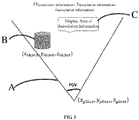
- the association information may be displayed in an area within the visual field A excluding the target display area B, such as the area C.
- the three freedom degrees of the see-through near-eye display device is (x glass , y glass , z glass ).
- the visual field A of the device may be determined.
- the obtained three degrees of freedom (x object , y object , z object ) of the display object it may be determined that the display object is displayed in the area B, and the association information may be displayed on the right side of the visual field A.
- the three freedom degrees of the association information may be determined as (x association information , y association information , z association information ), thereby determining that the display area of the association information is the area C.
- the characteristics of the background area may also be optimized according to display attributes, such as display color, display brightness, etc., of the association information.
- the characteristics of background area may include, but not limited to, background color, texture, brightness, distance, and the like.
- the background color can be set to a light background to enhance the text display contrast.
- the see-through near-eye display device determines that a display position of the association information for the display object as another area, which has no display content, within the visual field excluding the target display area, enabling both the display object and the associated information thereof to desirably match display capability of the device within a limited visual field for normal display, thereby improving the display capability of the device.
- the method may further include the following step.
- the target display area of the display object within the visual field of the see-through near-eye display device is updated, and a display area of the association information is re-determined based on the updated target display area.
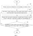
- FIG. 4 is a flow chart illustrating steps of an embodiment of a method for information display according to another exemplary embodiment of the present disclosure, including the following steps 401-404.
- step 401 association information corresponding to a display object is obtained.
- step 402 a target display area of the display object within a visual field of the see-through near-eye display device is determined.
- step 403 the association information is displayed in another area, having no display content, within the visual field excluding the target display area.
- step 404 it is determined whether the pose of the see-through near-eye display device and/or the display object is changed on the map. If yes, the process returns to step 402 and step 403; if not, the process ends.
- the pose information of the see-through near-eye display device and/or the display object may be obtained by the SLAM algorithm timing (for example, detecting 1000 poses in 1 second), and the pose information is compared with the pose information obtained in the previous cycle to determine whether the pose of the see-through near-eye display device and/or the display object is changed according to the pose information.
- a pose change of the see-through near-eye display device may be caused.
- the user interacts with the display object, for example, the user drags the display object through a handle or gesture interaction, such as dragging the display object from the right side of the FOV to the left side of the FOV, the pose change of the display object is caused.
- step 402 may be returned to re-determine the target display area of the display object within the visual field of the see-through near-eye display device, and then step 403 is performed to determine the display area of the association information based on the re-determined target display area.
- FIG. 5 and FIG. 6 show the change of spatial display position of association information caused by the change of relative position (orientation, distance) of the device and the display object.
- the display position of the association information can be adaptively updated according to the pose change of the device and/or the display object, so that the display of the association information is always adapted to the display capability of the device, thereby improving the display capability of the device.
- the present disclosure also provides embodiments of an apparatus for information display and a display device to which it is applied.
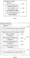
- FIG. 7 is a block diagram illustrating an apparatus for information display according to an exemplary embodiment of the present disclosure.
- the apparatus is provided in a see-through near-eye display device, and includes: an association information obtaining module 701, a target display area determination module 702, and an association information display module 703.
- the association information obtaining module 701 is configured to obtain association information corresponding to a display object.
- the target display area determination module 702 is configured to determine a target display area of the display object within a visual field of the see-through near-eye display device.
- the association information display module 703 is configured to display the association information in another area, having no display content, within the visual field excluding the target display area.
- the target display area of the display object within the visual field of the device is determined by the target display area determination module 702, and it is determined by the association information display module 703 that the display position for the association information of the display object is in another area having no display content within the visual field excluding the target display area, enabling the display object and associated information thereof to desirably match the display capability of the device within a limited visual field for normal display, thereby improving the display capability of the device.
- FIG. 8 is a block diagram illustrating an apparatus for information display according to another exemplary embodiment of the present disclosure.
- the target display area determination module 702 includes at least one of the following submodules: a map construction submodule 7021, a pose information obtaining submodule 7022, a visual field determination submodule 7023 and a target area determination submodule 7024.
- the map construction submodule 7021 is configured to construct a map of environment in which the see-through near-eye display device is located.
- the pose information obtaining submodule 7022 is configured to obtain pose information of the see-through near-eye display device and the display object on the map respectively.
- the visual field determination submodule 7023 is configured to determine the visual field of the see-through near-eye display device according to a filed angle of the see-through near-eye display device and the pose information of the see-through near-eye display device.
- the target area determination submodule 7024 is configured to determine, according to the pose information of the display object, an overlapping area of the display object within the visual field as the target display area of the display object within the visual field of the see-through near-eye display device.
- the target display area determination module 702 can determine, for example by using the SLAM algorithm, the target display area of the display object within the visual field of the device.
- a map of environment, in which the see-through near-eye display device is located is constructed firstly by the map construction submodule 7021, then the pose information of the see-through near-eye display device and the display object on the map is obtained by the pose information obtaining submodule 7022 respectively, and the visual field of the see-through near-eye display device is determined by the visual field determination submodule 7023.
- the target display area of the display object within the visual field of the see-through near-eye display device is determined by the target area determination submodule 7024 according to the pose information of the display object.
- the SLAM algorithm may be used to determine the target display area of the display object, which can improve the accuracy of the display object positioning, thereby improving the performance of the see-through near-eye display device.
- FIG. 9 is a block diagram illustrating an apparatus for information display according to another exemplary embodiment of the present disclosure.
- the apparatus further includes an update module 704.
- the update module 704 is configured to update, when a pose of the see-through near-eye display device and/or the display object on the map is changed, the target display area of the display object within the visual field of the see-through near-eye display device, and re-determine a display area of the association information based on the updated target display area.
- the pose change of the device and/or the display object can be detected by the update module 704, and the display position of the association information is adaptively updated based on the above change, always enabling the display of the association information to match the display capability of the device, thereby improving the display capability of the device.
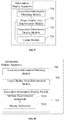
- FIG. 10 is a block diagram illustrating an apparatus for information display according to another exemplary embodiment of the present disclosure.
- the association information display module 703 may include at least one of the following submodules: an attribute determination submodule 7031 and a display submodule 7032.
- the attribute determination submodule 7031 is configured to determine a display attribute of the association information, the display attribute including a display area size required for the association information.
- the display submodule 7032 is configured to select, from areas of the visual field excluding the target display area, the another area fitting the display area size required for the association information for displaying the association information.
- the display attribute, such as the display area size and the like, required for the association information may be firstly determined by the attribute determination submodule 7031, and the area fitting the display area size required for the association information is selected, from the areas of the visual field excluding the target display area, as the display area of the association information, and the association information is displayed in the display area of the association information by the display submodule 7032, thereby ensuring the association information to be displayed completely in the display area of the association information.
- the association information obtaining module 701 is configured to obtain the association information corresponding to the display object, by scanning a two-dimensional code image corresponding to the display object, or from meta information attached to the display object.
- the association information can be provided in the two-dimensional code image or the meta information, so that the device can obtain the association information and improve the acquisition efficiency of the association information.
- FIG. 11 is a block diagram illustrating a display device 1100 according to an exemplary embodiment of the present disclosure.
- the device 1100 may be an AR device, an MR device, or the like.
- the device 1100 may include one or more of the following components: a processing component 1102, a memory 1104, a power component 1106, a multimedia component 1108, an audio component 1110, an input/output (I/O) interface 1112, a sensor component 1114, and a communication component 1116.
- a processing component 1102 a memory 1104, a power component 1106, a multimedia component 1108, an audio component 1110, an input/output (I/O) interface 1112, a sensor component 1114, and a communication component 1116.
- the processing component 1102 typically controls overall operations of the device 1100, such as the operations associated with display, data communications, camera operations, and recording operations.
- the processing component 1102 may include one or more processors 1120 to execute instructions for performing all or part of steps in the forgoing method.
- the processing component 1102 may include one or more modules which facilitate the interaction between the processing component 1102 and other components.
- the processing component 1102 may include a multimedia module to facilitate the interaction between the multimedia component 1108 and the processing component 1102.
- the memory 1104 is configured to store various types of data to support the operation of the device 1100. Examples of such data include instructions for any applications or methods operated on the device 1100, contact data, phonebook data, messages, pictures, video, etc.
- the memory 1104 may be implemented using any type of volatile or non-volatile memory devices, or a combination thereof, such as a static random access memory (SRAM), an electrically erasable programmable read-only memory (EEPROM), an erasable programmable read-only memory (EPROM), a programmable read-only memory (PROM), a read-only memory (ROM), a magnetic memory, a flash memory, a magnetic or optical disk.
- SRAM static random access memory
- EEPROM electrically erasable programmable read-only memory
- EPROM erasable programmable read-only memory
- PROM programmable read-only memory
- ROM read-only memory
- magnetic memory a magnetic memory
- flash memory a flash memory
- magnetic or optical disk a magnetic
- the power component 1106 provides power to various components of the device 1100.
- the power component 1106 may include a power management system, one or more power sources, and any other components associated with the generation, management, and distribution of power in the device 1100.
- the multimedia component 1108 includes a screen providing an output interface between the device 1100 and the user.
- the screen may include a liquid crystal display (LCD) and a touch panel (TP). If the screen includes the touch panel, the screen may be implemented as a touch screen to receive input signals from the user.
- the touch panel includes one or more touch sensors to sense touches, swipes, and gestures on the touch panel. The touch sensors may not only sense a boundary of a touch or swipe action, but also sense a period of time and a pressure associated with the touch or swipe action.
- the multimedia component 1108 includes a front camera and/or a back camera. The camera may receive an external multimedia datum while the device 1100 is in an operation mode, such as a photographing mode or a video mode. Each of the cameras may be a fixed optical lens system or have focus and optical zoom capability.
- the audio component 1110 is configured to output and/or input audio signals.
- the audio component 1110 includes a microphone ('MIC') configured to receive an external audio signal when the device 1100 is in an operation mode, such as a recording mode and a voice recognition mode.
- the received audio signal may be further stored in the memory 1104 or transmitted via the communication component 1116.
- the audio component 1110 further includes a speaker to output audio signals.
- the I/O interface 1112 provides an interface between the processing component 1102 and peripheral interface modules, such as a keyboard, a click wheel, buttons, and the like.
- the buttons may include, but are not limited to, a home button, a volume button, a starting button, and a locking button.
- the sensor component 1114 includes one or more sensors to provide status assessments of various aspects of the device 1100.
- the sensor component 1114 may detect an open/closed status of the device 1100, relative positioning of components, e.g., the display of the device 1100.
- the sensor component 1114 may also detect a change in position of the device 1100 or a component of the device 1100, a presence or absence of user contact with the device 1100, an orientation or an acceleration/deceleration of the device 1100, and a change in temperature of the device 1100.
- the sensor component 1114 may include a proximity sensor configured to detect the presence of nearby objects without any physical contact.
- the sensor component 1114 may also include a light sensor, such as a CMOS or CCD image sensor, for use in imaging applications.
- the sensor component 1114 may also include an accelerometer sensor, a gyroscope sensor, a magnetic sensor, a pressure sensor, or a temperature sensor.
- the communication component 1116 is configured to facilitate communication, wired or wirelessly, between the device 1100 and other devices.
- the device 1100 can access a wireless network based on a communication standard, such as WiFi, 4G, or 5G, or a combination thereof.
- the communication component 1116 receives a broadcast signal from an external broadcast management system or broadcasts associated information via a broadcast channel.
- the communication component 1116 further includes a near field communication (NFC) module to facilitate short-range communications.
- NFC near field communication
- the communication component 1116 may be implemented based on a radio frequency identification (RFID) technology, an infrared data association (IrDA) technology, an ultra-wideband (UWB) technology, a Bluetooth (BT) technology, and other technologies.
- RFID radio frequency identification
- IrDA infrared data association
- UWB ultra-wideband
- BT Bluetooth
- the device 1100 may be implemented with one or more application specific integrated circuits (ASICs), digital signal processors (DSPs), digital signal processing devices (DSPDs), programmable logic devices (PLDs), field programmable gate arrays (FPGAs), controllers, micro-controllers, microprocessors, or other electronic components, to perform above methods.
- ASICs application specific integrated circuits
- DSPs digital signal processors
- DSPDs digital signal processing devices
- PLDs programmable logic devices
- FPGAs field programmable gate arrays
- controllers micro-controllers, microprocessors, or other electronic components, to perform above methods.
- non-transitory computer-readable storage medium such as the memory 1104 including instructions.
- the instructions are executable by the processor 1120 in the device 1100, for performing the above-described methods.
- the non-transitory computer-readable storage medium may be a ROM, a RAM, a CD-ROM, a magnetic tape, a floppy disc, an optical data storage device, and the like.
- the instructions in the storage medium when executed by the processor, causes the device 1100 to perform a method for information display, including: obtaining association information corresponding to a display object; determining a target display area of the display object within a visual field of the see-through near-eye display device; and displaying the association information in another area, having no display content, within the visual field excluding the target display area.
Landscapes
- Engineering & Computer Science (AREA)
- Physics & Mathematics (AREA)
- Theoretical Computer Science (AREA)
- General Physics & Mathematics (AREA)
- Multimedia (AREA)
- General Engineering & Computer Science (AREA)
- Signal Processing (AREA)
- Human Computer Interaction (AREA)
- Computer Vision & Pattern Recognition (AREA)
- Geometry (AREA)
- Optics & Photonics (AREA)
- Computer Hardware Design (AREA)
- User Interface Of Digital Computer (AREA)
- Processing Or Creating Images (AREA)
Abstract
Description
- The present disclosure relates to the field of information display technologies, and more particularly, to a method and an apparatus for information display, and a display device.
- With the development of information technology, augmented reality (AR)/ mixed reality (MR) display glasses may become the next mobile platform, and existing AR/MR devices have already shown the potential of this platform. Its capabilities of spatial positioning, Simultaneously Location and Mapping (SLAM), and digital light field display can bring a new visual interaction experience, such as holographic model sharing, reproduction and the like, between multiple users.
- However, new user experience also faces many technical challenges, for example, how to correctly display the received shared content and related information thereof in a very limited display field of view (FOV) of the AR/MR devices.
- In order to overcome the problem in the related art, the present disclosure provides a method and an apparatus for information display, and a display device.
- According to a first aspect of the embodiments of the present disclosure, there is provided a method for information display. The method is applied to a see-through near-eye display device and includes:
- obtaining association information corresponding to a display object;
- determining a target display area of the display object within a visual field of the see-through near-eye display device; and
- displaying the association information in a second area within the visual field excluding the target display area, the second area having no display content.
- In an embodiment, the determining a target display area of the display object within a visual field of the see-through near-eye display device includes:
- constructing a map of environment in which the see-through near-eye display device is located;
- obtaining pose information of the see-through near-eye display device and the display object on the map respectively;
- determining the visual field of the see-through near-eye display device according to a filed angle of the see-through near-eye display device and the pose information of the see-through near-eye display device; and
- determining, according to the pose information of the display object, an overlapping area of the display object within the visual field as the target display area of the display object within the visual field of the see-through near-eye display device.
- In an embodiment, the method further includes:
updating, when a pose of the see-through near-eye display device and/or the display object on the map is changed, the target display area of the display object within the visual field of the see-through near-eye display device, and determining a display area of the association information based on the updated target display area. - In an embodiment, the displaying the association information in the second area within the visual field excluding the target display area includes:
- determining a display attribute of the association information, the display attribute including a display area size required for the association information; and
- selecting, from areas of the visual field excluding the target display area, the second area fitting the display area size required for the association information to display the association information.
- In an embodiment, the obtaining association information corresponding to a display object includes:
obtaining, by scanning a two-dimensional code image corresponding to the display object, or from meta information attached with the display object, the association information corresponding to the display object. - According to a second aspect of the embodiments of the present disclosure, there is provided an apparatus for information display, the apparatus is applied to a see-through near-eye display apparatus and includes:
- an association information obtaining module, configured to obtain association information corresponding to a display object;
- a target display area determination module, configured to determine a target display area of the display object within a visual field of the see-through near-eye display device; and
- an association information display module, configured to display the association information in a second area within the visual field excluding the target display area, the second area having no display content.
- In an embodiment, the target display area determination module includes:
- a map construction submodule, configured to construct a map of environment in which the see-through near-eye display device is located;
- a pose information obtaining submodule, configured to obtain pose information of the see-through near-eye display device and the display object on the map respectively;
- a visual field determination submodule, configured to determine the visual field of the see-through near-eye display device according to an filed angle of the see-through near-eye display device and the pose information of the see-through near-eye display device; and
- a target area determination submodule, configured to determine, according to the pose information of the display object, an overlapping area of the display object within the visual field as the target display area of the display object within the visual field of the see-through near-eye display device.
- In an embodiment, the apparatus further includes:
an update module, configured to update, when a pose of the see-through near-eye display device and/or the display object on the map is changed, the target display area of the display object within the visual field of the see-through near-eye display device, and determine a display area of the association information based on the updated target display area. - In an embodiment, the association information display module includes:
- an attribute determination submodule, configured to determine a display attribute of the association information, the display attribute comprising a display area size required for the association information; and
- a display submodule, configured to select, from areas of the visual field excluding the target display area, the second area fitting the display area size required for the association information to display the association information.
- According to a third aspect of the embodiments of the present disclosure, there is provided a display device, including:
- a processor; and
- a memory for storing instructions executable by the processor;
- wherein, the processor is configured to:
- obtain association information corresponding to a display object;
- determine a target display area of the display object within a visual field of the see-through near-eye display device; and
- display the association information in a second area within the visual field excluding the target display area, the second area having no display content.
- According to a third aspect of the embodiments of the present disclosure, there is provided a non-transitory computer-readable storage medium having stored thereon instructions that, when executed by a processor of a see-through near-eye display device, cause the see-through near-eye display device to perform a method for information display. The method includes: obtaining association information corresponding to a display object; determining a target display area of the display object within a visual field of the see-through near-eye display device; and displaying the association information in a second area within the visual field excluding the target display area, the second area having no display content.
- The technical solution provided by the embodiments of the present disclosure may include the following beneficial effects.
- In the embodiments, according to the target display area of the display object within the visual field of device, the see-through near-eye display device determines that a display position of the association information for the display object as another area, which has no display content, within the visual field excluding the target display area, enabling both the display object and the associated information thereof to desirably match display capability of the device within a limited visual field for normal display, thereby improving the display capability of the device.
- It should be understood that the above general description and the detailed description below are merely exemplary and explanatory, and do not limit the present disclosure.
- The accompanying drawings herein, which are incorporated in and constitute a part of this specification, illustrate embodiments consistent with the present disclosure and, together with the description, serve to explain the principles of the present disclosure.
-
FIG. 1 is a flow chart illustrating steps of an embodiment of a method for information display according to an exemplary embodiment of the present disclosure; -
FIG. 2 is a schematic diagram illustrating display of a device according to an exemplary embodiment of the present disclosure; -
FIG. 3 is a schematic diagram illustrating two-dimensional display of a device according to an exemplary embodiment of the present disclosure; -
FIG. 4 is a flow chart illustrating steps of an embodiment of a method for information display according to another exemplary embodiment of the present disclosure; -
FIG. 5 and FIG. 6 are schematic diagrams illustrating two-dimensional display of another device according to an exemplary embodiment of the present disclosure; -
FIG. 7 is a block diagram illustrating an apparatus for information display according to an exemplary embodiment of the present disclosure; -
FIG. 8 is a block diagram illustrating an apparatus for information display according to another exemplary embodiment of the present disclosure; -
FIG. 9 is a block diagram illustrating an apparatus for information display according to another exemplary embodiment of the present disclosure; -
FIG. 10 is a block diagram illustrating an apparatus for information display according to another exemplary embodiment of the present disclosure; -
FIG. 11 is a block diagram illustrating a display device according to an exemplary embodiment of the present disclosure. - Reference will now be made in detail to exemplary embodiments, examples of which are illustrated in the accompanying drawings. The following description refers to the accompanying drawings in which the same numbers in different drawings represent the same or similar elements unless otherwise represented. The implementations set forth in the following description of exemplary embodiments do not represent all implementations consistent with the disclosure. Instead, they are merely examples of apparatuses and methods consistent with aspects related to the disclosure as recited in the appended claims.
- The terms used in the present disclosure are for the purpose of describing particular embodiments only, and are not intended to limit the disclosure. The singular forms 'one', 'the' and 'that' used in the present disclosure and the appended claims are also intended to include the plural forms unless the context clearly indicates otherwise. It should also be understood that the term 'and/or' as used herein refers to and includes any and all possible combinations of one or more related listed items.
- It should be understood that although the terms first, second, third, etc. may be used in the present disclosure to describe various information, such information should not be limited to these terms. These terms are only used to distinguish the same type of information from each other. For example, the first information may also be referred to as second information without departing from the scope of the present disclosure. Similarly, the second information may also be referred to as the first information. Depending on the context, the word 'if' as used herein may be interpreted as 'when' or 'while' or 'in response to determination'.
-
FIG. 1 is a flow chart illustrating steps of an embodiment of a method for information display according to an exemplary embodiment of the present disclosure. The method may be applied to a see-through near-eye display device. For example, the see-through near-eye display device may include, but is not limited to, an augmented reality (AR) device, a mixed reality (MR) device, and the like. - As shown in
FIG. 1 , the embodiment of the present disclosure may include the following steps 101-103. - In
step 101, association information corresponding to a display object is obtained. - In an embodiment, the display object may be virtual display content associated with a current geographic location where the see-through near-eye display device is located. For example, the display object may include shared content of the current geographic location. The see-through near-eye display device may receive the shared content related to the current geographic location through a wireless network.
- The association information corresponding to the display object may include content predetermined for the display object, and for example, different association information may be predetermined according to different display objects. The associated information may be represented in the form of text, pictures, video, animation, models, and the like.
- As an example, the association information may include text description information, user comments, product prices, voice description information, and the like related to the display object.
- In an embodiment of the embodiment of the present disclosure,
step 101 may further include the following sub-step. - By scanning a two-dimensional code image corresponding to the display object, or from meta information attached to the display object, the association information corresponding to the display object is obtained.
- In one embodiment, the two-dimensional code image may be generated for association information of different display objects, and the two-dimensional code image is added to the display object. When the see-through near-eye display device displays the display object, the two-dimensional code image may be scanned by an image capturing apparatus of the see-through near-eye display device, and the association information in the two-dimensional code image may be obtained by an image recognition technology.
- In another embodiment, the association information of the display object may be attached to the display object as the meta information (also referred to as metadata) of the display object, and when the display object is displayed by the see-through near-eye display device, the association information in the two-dimensional code image may be obtained from the meta information. In the embodiment, the meta information is information used for describing data, and may include information describing an element or attribute (name, size, data type, etc.) of data, or its structure (length, field, data column), or its related data (where it is located, how to contact, owner).
- The present disclosure is not limited to the above two ways of obtaining the association information, and those skilled in the art may use other methods to obtain the association information of the display object.
- In
step 102, a target display area of the display object within a visual field of the see-through near-eye display device is determined. - In an embodiment, the visual field of the see-through near-eye display device may be a spatial range that can be displayed by the see-through near-eye display device.
- In an embodiment of the present disclosure,
step 102 may further include the following sub-steps S11-S14. - In sub-step S11, a map of environment, in which the see-through near-eye display device is located, is constructed.
- As an example, the map may include, but is not limited to, one of the following maps: a feature point map, a grid map, a topological map, a point cloud map, and the like.
- In an embodiment, a mapping method of Simultaneous Localization and Mapping (SLAM) algorithm can be used to construct the map of the environment in which the see-through near-eye display device is located.
- A mapping method in the SLAM may include the following steps, but it should be understood that the embodiment is not limited to the following mapping method, and those skilled in the art may use other mapping methods to construct the map.
- Firstly, original point clouds of the current environment are obtained through a depth sensor (such as a binocular camera, structured light, Time of Flight (TOF), etc.) in the see-through near-eye display device.
- Then, the original point clouds in different perspectives are stitched together to obtain a complete point cloud of the current scene. In one embodiment, stitching of the point clouds can be implemented by a manner of Iterative Closest Point (ICP) or motion tracking assistance.
- Finally, processing, such as point cloud processing, grid generation and the like, is performed to the complete point cloud of the current scene. In an embodiment, the processing, such as point cloud processing, grid generation and the like, may include, but is not limited to, the following processing methods: octree map (OctoMap) reconstruction method, Truncated Signed Distance Function (TSDF) reconstruction, Poisson (location) reconstruction and the like.
- In sub-step S12, pose information of the see-through near-eye display device and the display object on the map are obtained respectively.
- In an embodiment, the pose information represents position and posture of the see-through near-eye display device or the display object in the space. As an example, the pose information may include a six-degree-of-freedom (6DOF) pose of the see-through near-eye device or the display object, wherein the six-degree-of-freedom pose may be position information (x, y, z) of freedom degrees of movement along three orthogonal coordinate axes of x, y, and z, and angular information (pitch, yaw, roll) of freedom degrees of rotation around the three coordinate axes.
- In one embodiment, the positioning method of the SLAM algorithm (such as a motion tracking) can be used to perform motion tracking on the device or display object to determine the pose information of the see-through near-eye display device or the display object on the reconstructed map.
- One of the motion tracking methods may include the following models: tracking with motion model, tracking with reference key frame, and relocalization.
- The tracking with motion model may be implemented as follows. Assuming that the device or the display object (the device or the display object may be collectively referred to as a target) is moved at a constant speed, the pose and velocity of the previous frame can be used to estimate the pose of the current frame. The speed of the previous frame can be calculated from the pose of preceding frames. This model is suitable for situations where the speed and direction of motion are relatively uniform without large rotations. For the targets with more random movement, the following two models may be used.
- The tracking with reference key frame may be implemented as follows. If the tracking with motion model has failed, the nearest keyframe may be matched firstly, since the distance between the current frame and the previous keyframe is not very far. In implementation, BoW (Bag of Words Model) can be used to speed up matching. In an embodiment, the BoW of the current frame can be calculated firstly, and the initial pose is set to the pose of the previous frame; secondly, feature matching is sought based on the pose and BoW dictionary; finally, the matched features are used to optimize the pose.
- The relocalization may be implemented as follows. If the matching between the current frame and the nearest neighbor keyframe also fails, it means that the current frame has been lost and the real position may not be determined. Accordingly, all keyframes may be matched to determine whether the right position can be found. Firstly, the Bow vector of the current frame is calculated. Secondly, several keyframes are selected based on the BoW dictionary as alternatives. Then, keyframes with enough matched feature points are determined. Finally, feature point matching is used to iteratively solve poses. If there are enough interior points for the keyframe, the optimized pose of the keyframe is selected.
- In sub-step S13, the visual field of the see-through near-eye display device is determined according to a filed angle of the see-through near-eye display device and pose information of the see-through near-eye display device.
- In an embodiment, according to the filed angle (also referred to as FOV, Field of View) of the see-through near-eye display device and its pose information on the map, the display range in a three-dimensional space, that is, the visual field of the see-through near-eye display device, can be determined.
- For example, referring to the device display diagram of
FIG. 2 , the visual field of a see-through near-eye display device 10 is an area A, and the area A is the three-dimensional space area between a far plane A2 and a near plane A1. The position of each of the near plane A1 and the far plane A2 in the space may be determined by the pose information of the see-through near-eye display device 10. The plane size of each of the near plane A1 and the far plane A2 in the space may be determined by the filed angle of the see-through near-eye display device 10. In sub-step S14, according to the pose information of the display object, an overlapping area of the display object within the visual field is determined as the target display area of the display object within the visual field of the see-through near-eye display device. - According to the pose information of the display object, the three-dimensional space range corresponding to the display object may be determined, and then the overlapping area of the three-dimensional space range and the visual field of the see-through near-eye display device is obtained as the target display area of the display object within the visual field.
- For example, as shown in
FIG. 2 , according to the pose information of the display object, it can be determined that the target display area of the display object within the visual field is an area B. - Referring back to
FIG. 1 , instep 103, the association information is displayed in another area (i.e., a second area), having no display content, within the visual field excluding the target display area. - After it is determined that the display object is in the target display area within the visual field, the association information may be displayed in another area having no display content within the visual field excluding the target display area. In an embodiment of the embodiments of the present disclosure,
step 103 may further include the following sub-steps S21-S22. - In sub-step S21, a display attribute of the association information is determined, the display attribute including a display area size required for the association information.
- The display attribute of the associated information may be predetermined, or may also be customized by the user prior to display, which is not limited in the embodiment.
- As an example, the display attribute of the association information may include, but not be limited to: display area size required for the association information, display color and display brightness of the associated information, and the like.
- In sub-step S22, it is selected, from areas of the visual field excluding the target display area, the another area fitting the display area size required for the association information to display the association information.
- In an embodiment, the area fitting the display area size required for the association information may include an area with a size greater than or equal to the size of the display area.
- In an embodiment, if the see-through near-eye display device has the ability to reconstruct the geometric information of the plane in the scene, occlusion relationship of the geometric information may be considered in the determination of the display area of the association information, that is, the selected area for displaying the association information may be an area without occlusion.
- For example, in
FIG. 2 , after the visual field A of the see-through near-eye display device 10 and the target display area B of the display object are determined, the association information may be displayed in an area within the visual field A excluding the target display area B, such as the area C. - For another example, as shown in the two-dimensional display schematic diagram of the device in
FIG. 3 , in the two-dimensional display schematic diagram, the three freedom degrees of the see-through near-eye display device (assumed to be AR/MR glasses) is (xglass, yglass, zglass). According to (xglass, yglass, zglass) and the FOV of the device, the visual field A of the device may be determined. According to the obtained three degrees of freedom (xobject, yobject, zobject) of the display object, it may be determined that the display object is displayed in the area B, and the association information may be displayed on the right side of the visual field A. For example, according to the display area having no display content within the visual field A, the three freedom degrees of the association information may be determined as (xassociation information, yassociation information, zassociation information), thereby determining that the display area of the association information is the area C. - In one embodiment, when the association information is displayed, the characteristics of the background area may also be optimized according to display attributes, such as display color, display brightness, etc., of the association information. The characteristics of background area may include, but not limited to, background color, texture, brightness, distance, and the like. For example, when the association information is black text, the background color can be set to a light background to enhance the text display contrast.
- In the embodiment, according to the received target display area of the target object within the visual field of the device, the see-through near-eye display device determines that a display position of the association information for the display object as another area, which has no display content, within the visual field excluding the target display area, enabling both the display object and the associated information thereof to desirably match display capability of the device within a limited visual field for normal display, thereby improving the display capability of the device.
- In an embodiment of the embodiments of the present disclosure, the method may further include the following step.
- When a pose of the see-through near-eye display device and/or the display object on the map is changed, the target display area of the display object within the visual field of the see-through near-eye display device is updated, and a display area of the association information is re-determined based on the updated target display area.
- In an embodiment, based on the above pose change of scene,
FIG. 4 is a flow chart illustrating steps of an embodiment of a method for information display according to another exemplary embodiment of the present disclosure, including the following steps 401-404. - In
step 401, association information corresponding to a display object is obtained. - In
step 402, a target display area of the display object within a visual field of the see-through near-eye display device is determined. - In
step 403, the association information is displayed in another area, having no display content, within the visual field excluding the target display area. - In
step 404, it is determined whether the pose of the see-through near-eye display device and/or the display object is changed on the map. If yes, the process returns to step 402 and step 403; if not, the process ends. - In an embodiment, the pose information of the see-through near-eye display device and/or the display object may be obtained by the SLAM algorithm timing (for example, detecting 1000 poses in 1 second), and the pose information is compared with the pose information obtained in the previous cycle to determine whether the pose of the see-through near-eye display device and/or the display object is changed according to the pose information.
- In an embodiment, when the user moves the see-through near-eye display device, a pose change of the see-through near-eye display device may be caused. When the user interacts with the display object, for example, the user drags the display object through a handle or gesture interaction, such as dragging the display object from the right side of the FOV to the left side of the FOV, the pose change of the display object is caused.
- When the pose change of the see-through near-eye display device and/or the display object is detected,
step 402 may be returned to re-determine the target display area of the display object within the visual field of the see-through near-eye display device, and then step 403 is performed to determine the display area of the association information based on the re-determined target display area. - For example, taking the pose in
FIG. 3 as the original pose of the device and the display object,FIG. 5 and FIG. 6 show the change of spatial display position of association information caused by the change of relative position (orientation, distance) of the device and the display object. - In this embodiment, the display position of the association information can be adaptively updated according to the pose change of the device and/or the display object, so that the display of the association information is always adapted to the display capability of the device, thereby improving the display capability of the device.
- Corresponding to the embodiments of the method for information display described above, the present disclosure also provides embodiments of an apparatus for information display and a display device to which it is applied.
-
FIG. 7 is a block diagram illustrating an apparatus for information display according to an exemplary embodiment of the present disclosure. The apparatus is provided in a see-through near-eye display device, and includes: an associationinformation obtaining module 701, a target displayarea determination module 702, and an associationinformation display module 703. - The association
information obtaining module 701 is configured to obtain association information corresponding to a display object. - The target display
area determination module 702 is configured to determine a target display area of the display object within a visual field of the see-through near-eye display device. - The association
information display module 703 is configured to display the association information in another area, having no display content, within the visual field excluding the target display area. - As can be seen from the above embodiment, after the association
information obtaining module 701 obtains the association information corresponding to the display object, the target display area of the display object within the visual field of the device is determined by the target displayarea determination module 702, and it is determined by the associationinformation display module 703 that the display position for the association information of the display object is in another area having no display content within the visual field excluding the target display area, enabling the display object and associated information thereof to desirably match the display capability of the device within a limited visual field for normal display, thereby improving the display capability of the device. -
FIG. 8 is a block diagram illustrating an apparatus for information display according to another exemplary embodiment of the present disclosure. On the basis of the above embodiment shown inFIG. 7 , the target displayarea determination module 702 includes at least one of the following submodules: amap construction submodule 7021, a poseinformation obtaining submodule 7022, a visualfield determination submodule 7023 and a targetarea determination submodule 7024. - The
map construction submodule 7021 is configured to construct a map of environment in which the see-through near-eye display device is located. - The pose
information obtaining submodule 7022 is configured to obtain pose information of the see-through near-eye display device and the display object on the map respectively. - The visual
field determination submodule 7023 is configured to determine the visual field of the see-through near-eye display device according to a filed angle of the see-through near-eye display device and the pose information of the see-through near-eye display device. - The target
area determination submodule 7024 is configured to determine, according to the pose information of the display object, an overlapping area of the display object within the visual field as the target display area of the display object within the visual field of the see-through near-eye display device. - As can be seen from the above embodiment, the target display
area determination module 702 can determine, for example by using the SLAM algorithm, the target display area of the display object within the visual field of the device. For example, a map of environment, in which the see-through near-eye display device is located, is constructed firstly by themap construction submodule 7021, then the pose information of the see-through near-eye display device and the display object on the map is obtained by the poseinformation obtaining submodule 7022 respectively, and the visual field of the see-through near-eye display device is determined by the visualfield determination submodule 7023. Finally, the target display area of the display object within the visual field of the see-through near-eye display device is determined by the targetarea determination submodule 7024 according to the pose information of the display object. The SLAM algorithm may be used to determine the target display area of the display object, which can improve the accuracy of the display object positioning, thereby improving the performance of the see-through near-eye display device. -
FIG. 9 is a block diagram illustrating an apparatus for information display according to another exemplary embodiment of the present disclosure. On the basis of the above embodiment shown inFIG. 7 , the apparatus further includes anupdate module 704. - The
update module 704 is configured to update, when a pose of the see-through near-eye display device and/or the display object on the map is changed, the target display area of the display object within the visual field of the see-through near-eye display device, and re-determine a display area of the association information based on the updated target display area. - As can be seen from the above embodiment, the pose change of the device and/or the display object can be detected by the
update module 704, and the display position of the association information is adaptively updated based on the above change, always enabling the display of the association information to match the display capability of the device, thereby improving the display capability of the device. -
FIG. 10 is a block diagram illustrating an apparatus for information display according to another exemplary embodiment of the present disclosure. On the basis of the above embodiment shown inFIG. 7 , the associationinformation display module 703 may include at least one of the following submodules: anattribute determination submodule 7031 and adisplay submodule 7032. - The
attribute determination submodule 7031 is configured to determine a display attribute of the association information, the display attribute including a display area size required for the association information. - The
display submodule 7032 is configured to select, from areas of the visual field excluding the target display area, the another area fitting the display area size required for the association information for displaying the association information. - As can be seen from the above embodiment, when the association information display is performed, the display attribute, such as the display area size and the like, required for the association information may be firstly determined by the
attribute determination submodule 7031, and the area fitting the display area size required for the association information is selected, from the areas of the visual field excluding the target display area, as the display area of the association information, and the association information is displayed in the display area of the association information by thedisplay submodule 7032, thereby ensuring the association information to be displayed completely in the display area of the association information. - In an embodiment, the association
information obtaining module 701 is configured to obtain the association information corresponding to the display object, by scanning a two-dimensional code image corresponding to the display object, or from meta information attached to the display object. - As can be seen from the above embodiment, the association information can be provided in the two-dimensional code image or the meta information, so that the device can obtain the association information and improve the acquisition efficiency of the association information.
- For the apparatus embodiments, since they basically correspond to the method embodiments, reference may be made to the description of the method embodiments. The apparatus embodiments described above are merely illustrative, wherein the modules described as separate components may be or may not be physically separate, and the components shown as units may be or may not be physical units, that is, they may be located at one place, or may be distributed at multiple networks. Some or all of the modules may be selected according to actual needs to achieve the objectives of the present disclosure. Those of ordinary skill in the art can understand and implement without any creative effort.
-
FIG. 11 is a block diagram illustrating adisplay device 1100 according to an exemplary embodiment of the present disclosure. Thedevice 1100 may be an AR device, an MR device, or the like. - Referring to
FIG. 11 , thedevice 1100 may include one or more of the following components: aprocessing component 1102, amemory 1104, apower component 1106, amultimedia component 1108, anaudio component 1110, an input/output (I/O)interface 1112, asensor component 1114, and acommunication component 1116. - The
processing component 1102 typically controls overall operations of thedevice 1100, such as the operations associated with display, data communications, camera operations, and recording operations. Theprocessing component 1102 may include one ormore processors 1120 to execute instructions for performing all or part of steps in the forgoing method. Moreover, theprocessing component 1102 may include one or more modules which facilitate the interaction between theprocessing component 1102 and other components. For instance, theprocessing component 1102 may include a multimedia module to facilitate the interaction between themultimedia component 1108 and theprocessing component 1102. - The
memory 1104 is configured to store various types of data to support the operation of thedevice 1100. Examples of such data include instructions for any applications or methods operated on thedevice 1100, contact data, phonebook data, messages, pictures, video, etc. Thememory 1104 may be implemented using any type of volatile or non-volatile memory devices, or a combination thereof, such as a static random access memory (SRAM), an electrically erasable programmable read-only memory (EEPROM), an erasable programmable read-only memory (EPROM), a programmable read-only memory (PROM), a read-only memory (ROM), a magnetic memory, a flash memory, a magnetic or optical disk. - The
power component 1106 provides power to various components of thedevice 1100. Thepower component 1106 may include a power management system, one or more power sources, and any other components associated with the generation, management, and distribution of power in thedevice 1100. - The
multimedia component 1108 includes a screen providing an output interface between thedevice 1100 and the user. In some embodiments, the screen may include a liquid crystal display (LCD) and a touch panel (TP). If the screen includes the touch panel, the screen may be implemented as a touch screen to receive input signals from the user. The touch panel includes one or more touch sensors to sense touches, swipes, and gestures on the touch panel. The touch sensors may not only sense a boundary of a touch or swipe action, but also sense a period of time and a pressure associated with the touch or swipe action. In some embodiments, themultimedia component 1108 includes a front camera and/or a back camera. The camera may receive an external multimedia datum while thedevice 1100 is in an operation mode, such as a photographing mode or a video mode. Each of the cameras may be a fixed optical lens system or have focus and optical zoom capability. - The
audio component 1110 is configured to output and/or input audio signals. For example, theaudio component 1110 includes a microphone ('MIC') configured to receive an external audio signal when thedevice 1100 is in an operation mode, such as a recording mode and a voice recognition mode. The received audio signal may be further stored in thememory 1104 or transmitted via thecommunication component 1116. In some embodiments, theaudio component 1110 further includes a speaker to output audio signals. - The I/
O interface 1112 provides an interface between theprocessing component 1102 and peripheral interface modules, such as a keyboard, a click wheel, buttons, and the like. The buttons may include, but are not limited to, a home button, a volume button, a starting button, and a locking button. - The
sensor component 1114 includes one or more sensors to provide status assessments of various aspects of thedevice 1100. For example, thesensor component 1114 may detect an open/closed status of thedevice 1100, relative positioning of components, e.g., the display of thedevice 1100. Thesensor component 1114 may also detect a change in position of thedevice 1100 or a component of thedevice 1100, a presence or absence of user contact with thedevice 1100, an orientation or an acceleration/deceleration of thedevice 1100, and a change in temperature of thedevice 1100. Thesensor component 1114 may include a proximity sensor configured to detect the presence of nearby objects without any physical contact. Thesensor component 1114 may also include a light sensor, such as a CMOS or CCD image sensor, for use in imaging applications. In some embodiments, thesensor component 1114 may also include an accelerometer sensor, a gyroscope sensor, a magnetic sensor, a pressure sensor, or a temperature sensor. - The
communication component 1116 is configured to facilitate communication, wired or wirelessly, between thedevice 1100 and other devices. Thedevice 1100 can access a wireless network based on a communication standard, such as WiFi, 4G, or 5G, or a combination thereof. In one exemplary embodiment, thecommunication component 1116 receives a broadcast signal from an external broadcast management system or broadcasts associated information via a broadcast channel. In one exemplary embodiment, thecommunication component 1116 further includes a near field communication (NFC) module to facilitate short-range communications. In one exemplary embodiment, thecommunication component 1116 may be implemented based on a radio frequency identification (RFID) technology, an infrared data association (IrDA) technology, an ultra-wideband (UWB) technology, a Bluetooth (BT) technology, and other technologies. - In exemplary embodiments, the
device 1100 may be implemented with one or more application specific integrated circuits (ASICs), digital signal processors (DSPs), digital signal processing devices (DSPDs), programmable logic devices (PLDs), field programmable gate arrays (FPGAs), controllers, micro-controllers, microprocessors, or other electronic components, to perform above methods. - In exemplary embodiments, there is also provided a non-transitory computer-readable storage medium, such as the
memory 1104 including instructions. The instructions are executable by theprocessor 1120 in thedevice 1100, for performing the above-described methods. For example, the non-transitory computer-readable storage medium may be a ROM, a RAM, a CD-ROM, a magnetic tape, a floppy disc, an optical data storage device, and the like. - The instructions in the storage medium, when executed by the processor, causes the
device 1100 to perform a method for information display, including: obtaining association information corresponding to a display object; determining a target display area of the display object within a visual field of the see-through near-eye display device; and displaying the association information in another area, having no display content, within the visual field excluding the target display area. - Other embodiments of the disclosure will be apparent to those skilled in the art from consideration of the specification and practice of the disclosure disclosed here. This specification is intended to cover any variations, uses, or adaptations of the disclosure following the general principles thereof and including such departures from the present disclosure as come within known or customary practice in the art. It is intended that the specification and examples be considered as exemplary only, with a true scope of the disclosure being indicated by the following claims.
- It will be appreciated that the present disclosure is not limited to the exact construction that has been described above and illustrated in the accompanying drawings, and that various modifications and changes can be made without departing from the scope thereof. It is intended that the scope of the disclosure only be limited by the appended claims.
Claims (15)
- A method for information display, applied to a see-through near-eye display device, the method comprising:obtaining association information corresponding to a display object;determining a target display area of the display object within a visual field of the see-through near-eye display device; anddisplaying the association information in a second area within the visual field excluding the target display area, the second area having no display content.
- The method according to claim 1, wherein the determining a target display area of the display object within a visual field of the see-through near-eye display device comprises:constructing a map of environment in which the see-through near-eye display device is located;obtaining pose information of the see-through near-eye display device and the display object on the map respectively;determining the visual field of the see-through near-eye display device according to a filed angle of the see-through near-eye display device and the pose information of the see-through near-eye display device; anddetermining, according to the pose information of the display object, an overlapping area of the display object within the visual field as the target display area of the display object within the visual field of the see-through near-eye display device.
- The method according to claim 2, further comprising:
updating, when a pose of the see-through near-eye display device and/or the display object on the map is changed, the target display area of the display object within the visual field of the see-through near-eye display device, and determining a display area of the association information based on the updated target display area. - The method according to any one of the claims 1-3, wherein the displaying the association information in a second area within the visual field excluding the target display area comprises:determining a display attribute of the association information, the display attribute comprising a display area size required for the association information; andselecting, from areas of the visual field excluding the target display area, the second area fitting the display area size required for the association information to display the association information.
- The method according to claim 1, wherein the obtaining association information corresponding to a display object comprises:
obtaining the association information corresponding to the display object by scanning a two-dimensional code image corresponding to the display object, or from meta information attached with the display object. - An apparatus for information display, being provided in a see-through near-eye display device and comprising:an association information obtaining module, configured to obtain association information corresponding to a display object;a target display area determination module, configured to determine a target display area of the display object within a visual field of the see-through near-eye display device; andan association information display module, configured to display the association information in a second area within the visual field excluding the target display area, the second area having no display content.
- The apparatus according to claim 6, wherein the target display area determination module comprises:a map construction submodule, configured to construct a map of environment in which the see-through near-eye display device is located;a pose information obtaining submodule, configured to obtain pose information of the see-through near-eye display device and the display object on the map respectively;a visual field determination submodule, configured to determine the visual field of the see-through near-eye display device according to an filed angle of the see-through near-eye display device and the pose information of the see-through near-eye display device; anda target area determination submodule, configured to determine, according to the pose information of the display object, an overlapping area of the display object within the visual field as the target display area of the display object within the visual field of the see-through near-eye display device.
- The apparatus according to claim 7, further comprising:
an update module, configured to update, when a pose of the see-through near-eye display device and/or the display object on the map is changed, the target display area of the display object within the visual field of the see-through near-eye display device, and determine a display area of the association information based on the updated target display area. - The apparatus according to any one of the claims 6-8, wherein the association information display module comprises:an attribute determination submodule, configured to determine a display attribute of the association information, the display attribute comprising a display area size required for the association information; anda display submodule, configured to select, from areas of the visual field excluding the target display area, the second area fitting the display area size required for the association information to display the association information.
- A display device, comprising:a processor; anda memory for storing instructions executable by the processor;wherein, the processor is configured to:obtain association information corresponding to a display object;determine a target display area of the display object within a visual field of the display device; anddisplay the association information in a second area within the visual field excluding the target display area, the second area having no display content.
- The display device according to claim 8, wherein in determining a target display area of the display object within a visual field of the display device, the processor is further configured to:construct a map of environment in which the display device is located;obtain pose information of the display device and the display object on the map respectively;determine the visual field of the display device according to a filed angle of the display device and the pose information of the display device; anddetermine, according to the pose information of the display object, an overlapping area of the display object within the visual field as the target display area of the display object within the visual field of the display device.
- The display device according to claim 11, wherein the processor is further configured to:
update, when at least one of a pose of the display device or the display object on the map is changed, the target display area of the display object within the visual field of the display device, and determine a display area of the association information based on the updated target display area. - The display device according to any one of claims 10-12, wherein in displaying the association information in a second area within the visual field excluding the target display area, the processor is further configured to:determine a display attribute of the association information, the display attribute comprising a display area size required for the association information; andselect, from areas of the visual field excluding the target display area, the second area fitting the display area size required for the association information to display the association information.
- The display device according to claim 10, wherein the processor is configured to obtain the association information corresponding to the display object by scanning a two-dimensional code image corresponding to the display object, or from meta information attached with the display object.
- A non-transitory computer-readable storage medium having stored thereon instructions that, when executed by a processor of a see-through near-eye display device, cause the see-through near-eye display device to perform a method for information display, the method comprising:obtaining association information corresponding to a display object;determining a target display area of the display object within a visual field of the see-through near-eye display device; anddisplaying the association information in a second area within the visual field excluding the target display area, the second area having no display content.
Applications Claiming Priority (1)
| Application Number | Priority Date | Filing Date | Title |
|---|---|---|---|
| CN201811331018.4A CN109582134B (en) | 2018-11-09 | 2018-11-09 | Information display method, device and display device |
Publications (1)
| Publication Number | Publication Date |
|---|---|
| EP3651144A1 true EP3651144A1 (en) | 2020-05-13 |
Family
ID=65921879
Family Applications (1)
| Application Number | Title | Priority Date | Filing Date |
|---|---|---|---|
| EP19208069.5A Pending EP3651144A1 (en) | 2018-11-09 | 2019-11-08 | Method and apparatus for information display, and display device |
Country Status (3)
| Country | Link |
|---|---|
| US (1) | US10931926B2 (en) |
| EP (1) | EP3651144A1 (en) |
| CN (1) | CN109582134B (en) |
Families Citing this family (4)
| Publication number | Priority date | Publication date | Assignee | Title |
|---|---|---|---|---|
| CN111178191B (en) * | 2019-11-11 | 2022-01-11 | 贝壳找房(北京)科技有限公司 | Information playing method and device, computer readable storage medium and electronic equipment |
| US11080862B2 (en) * | 2019-11-18 | 2021-08-03 | Ncku Research And Development Foundation | Reliability based keyframe switching system and method adaptable to ICP |
| CN111625093B (en) * | 2020-05-19 | 2023-08-01 | 昆明埃舍尔科技有限公司 | Dynamic scheduling display method of massive digital point cloud data in MR (magnetic resonance) glasses |
| CN113568595B (en) * | 2021-07-14 | 2024-05-17 | 上海炬佑智能科技有限公司 | Control method, device, equipment and medium of display assembly based on ToF camera |
Citations (2)
| Publication number | Priority date | Publication date | Assignee | Title |
|---|---|---|---|---|
| EP2657929A2 (en) * | 2012-04-08 | 2013-10-30 | Samsung Electronics Co., Ltd | Transparent display apparatus and method thereof |
| EP2757549A1 (en) * | 2013-01-22 | 2014-07-23 | Samsung Electronics Co., Ltd | Transparent display apparatus and method thereof |
Family Cites Families (8)
| Publication number | Priority date | Publication date | Assignee | Title |
|---|---|---|---|---|
| CN102446048B (en) * | 2010-09-30 | 2014-04-02 | 联想(北京)有限公司 | Information processing device and information processing method |
| US9583032B2 (en) * | 2012-06-05 | 2017-02-28 | Microsoft Technology Licensing, Llc | Navigating content using a physical object |
| KR102178892B1 (en) * | 2014-09-15 | 2020-11-13 | 삼성전자주식회사 | Method for providing an information on the electronic device and electronic device thereof |
| US10567641B1 (en) * | 2015-01-19 | 2020-02-18 | Devon Rueckner | Gaze-directed photography |
| US10740971B2 (en) * | 2015-01-20 | 2020-08-11 | Microsoft Technology Licensing, Llc | Augmented reality field of view object follower |
| JP6344311B2 (en) * | 2015-05-26 | 2018-06-20 | ソニー株式会社 | Display device, information processing system, and control method |
| US10578869B2 (en) * | 2017-07-24 | 2020-03-03 | Mentor Acquisition One, Llc | See-through computer display systems with adjustable zoom cameras |
| US10839576B2 (en) * | 2017-10-27 | 2020-11-17 | Magic Leap, Inc. | Virtual reticle for augmented reality systems |
-
2018
- 2018-11-09 CN CN201811331018.4A patent/CN109582134B/en active Active
-
2019
- 2019-11-08 US US16/677,973 patent/US10931926B2/en active Active
- 2019-11-08 EP EP19208069.5A patent/EP3651144A1/en active Pending
Patent Citations (2)
| Publication number | Priority date | Publication date | Assignee | Title |
|---|---|---|---|---|
| EP2657929A2 (en) * | 2012-04-08 | 2013-10-30 | Samsung Electronics Co., Ltd | Transparent display apparatus and method thereof |
| EP2757549A1 (en) * | 2013-01-22 | 2014-07-23 | Samsung Electronics Co., Ltd | Transparent display apparatus and method thereof |
Also Published As
| Publication number | Publication date |
|---|---|
| US20200154085A1 (en) | 2020-05-14 |
| CN109582134B (en) | 2021-07-23 |
| US10931926B2 (en) | 2021-02-23 |
| CN109582134A (en) | 2019-04-05 |
Similar Documents
| Publication | Publication Date | Title |
|---|---|---|
| US9779508B2 (en) | Real-time three-dimensional reconstruction of a scene from a single camera | |
| CN113822918B (en) | Scene depth and camera motion prediction method and device, electronic device and medium | |
| KR101433305B1 (en) | Mobile device based content mapping for augmented reality environment | |
| US10931926B2 (en) | Method and apparatus for information display, and display device | |
| EP2974509B1 (en) | Personal information communicator | |
| US11770551B2 (en) | Object pose estimation and tracking using machine learning | |
| US20220345621A1 (en) | Scene lock mode for capturing camera images | |
| CN110599593B (en) | Data synthesis method, device, equipment and storage medium | |
| WO2015048086A1 (en) | Approaches for simulating three-dimensional views | |
| KR20140122054A (en) | converting device for converting 2-dimensional image to 3-dimensional image and method for controlling thereof | |
| KR102722177B1 (en) | Depth estimation using neural networks | |
| JP2022518810A (en) | Positioning methods and devices based on shared maps, electronic devices and storage media | |
| US20200380741A1 (en) | Method and device for creating indoor environment map | |
| CN114581525A (en) | Attitude determination method and device, electronic device and storage medium | |
| CN112150560A (en) | Method, apparatus and computer storage medium for determining vanishing point | |
| CN111928861B (en) | Map construction method and device | |
| CN113989469A (en) | AR (augmented reality) scenery spot display method and device, electronic equipment and storage medium | |
| US11409241B2 (en) | Method and apparatus for adjusting holographic content and computer readable storage medium | |
| US20230215098A1 (en) | Method and system for creating and storing map target | |
| CN114898039A (en) | Three-dimensional model construction method and device, electronic equipment and storage medium | |
| WO2021121061A1 (en) | Method for configuring spatial position of virtual object, and electronic device | |
| EP4394702A1 (en) | Method and device for drawing spatial map, camera equipment and storage medium | |
| CN113532468A (en) | Navigation method and related equipment | |
| CN104835060B (en) | A kind of control methods of virtual product object and device | |
| CN114638949A (en) | Virtual object display method and device, electronic equipment and storage medium |
Legal Events
| Date | Code | Title | Description |
|---|---|---|---|
| PUAI | Public reference made under article 153(3) epc to a published international application that has entered the european phase |
Free format text: ORIGINAL CODE: 0009012 |
|
| STAA | Information on the status of an ep patent application or granted ep patent |
Free format text: STATUS: THE APPLICATION HAS BEEN PUBLISHED |
|
| AK | Designated contracting states |
Kind code of ref document: A1 Designated state(s): AL AT BE BG CH CY CZ DE DK EE ES FI FR GB GR HR HU IE IS IT LI LT LU LV MC MK MT NL NO PL PT RO RS SE SI SK SM TR |
|
| AX | Request for extension of the european patent |
Extension state: BA ME |
|
| STAA | Information on the status of an ep patent application or granted ep patent |
Free format text: STATUS: REQUEST FOR EXAMINATION WAS MADE |
|
| 17P | Request for examination filed |
Effective date: 20201110 |
|
| RBV | Designated contracting states (corrected) |
Designated state(s): AL AT BE BG CH CY CZ DE DK EE ES FI FR GB GR HR HU IE IS IT LI LT LU LV MC MK MT NL NO PL PT RO RS SE SI SK SM TR |
|
| STAA | Information on the status of an ep patent application or granted ep patent |
Free format text: STATUS: EXAMINATION IS IN PROGRESS |
|
| 17Q | First examination report despatched |
Effective date: 20220214 |
|
| GRAP | Despatch of communication of intention to grant a patent |
Free format text: ORIGINAL CODE: EPIDOSNIGR1 |
|
| STAA | Information on the status of an ep patent application or granted ep patent |
Free format text: STATUS: GRANT OF PATENT IS INTENDED |
|
| INTG | Intention to grant announced |
Effective date: 20260217 |