EP3650766A1 - Water leak-preventing non-powered humidifying module for air purifier - Google Patents
Water leak-preventing non-powered humidifying module for air purifier Download PDFInfo
- Publication number
- EP3650766A1 EP3650766A1 EP18827940.0A EP18827940A EP3650766A1 EP 3650766 A1 EP3650766 A1 EP 3650766A1 EP 18827940 A EP18827940 A EP 18827940A EP 3650766 A1 EP3650766 A1 EP 3650766A1
- Authority
- EP
- European Patent Office
- Prior art keywords
- water
- opening
- partition wall
- air cleaner
- space
- Prior art date
- Legal status (The legal status is an assumption and is not a legal conclusion. Google has not performed a legal analysis and makes no representation as to the accuracy of the status listed.)
- Granted
Links
Images
Classifications
-
- F—MECHANICAL ENGINEERING; LIGHTING; HEATING; WEAPONS; BLASTING
- F24—HEATING; RANGES; VENTILATING
- F24F—AIR-CONDITIONING; AIR-HUMIDIFICATION; VENTILATION; USE OF AIR CURRENTS FOR SCREENING
- F24F8/00—Treatment, e.g. purification, of air supplied to human living or working spaces otherwise than by heating, cooling, humidifying or drying
-
- F—MECHANICAL ENGINEERING; LIGHTING; HEATING; WEAPONS; BLASTING
- F24—HEATING; RANGES; VENTILATING
- F24F—AIR-CONDITIONING; AIR-HUMIDIFICATION; VENTILATION; USE OF AIR CURRENTS FOR SCREENING
- F24F6/00—Air-humidification, e.g. cooling by humidification
- F24F6/12—Air-humidification, e.g. cooling by humidification by forming water dispersions in the air
-
- F—MECHANICAL ENGINEERING; LIGHTING; HEATING; WEAPONS; BLASTING
- F24—HEATING; RANGES; VENTILATING
- F24F—AIR-CONDITIONING; AIR-HUMIDIFICATION; VENTILATION; USE OF AIR CURRENTS FOR SCREENING
- F24F11/00—Control or safety arrangements
- F24F11/0008—Control or safety arrangements for air-humidification
-
- F—MECHANICAL ENGINEERING; LIGHTING; HEATING; WEAPONS; BLASTING
- F24—HEATING; RANGES; VENTILATING
- F24F—AIR-CONDITIONING; AIR-HUMIDIFICATION; VENTILATION; USE OF AIR CURRENTS FOR SCREENING
- F24F11/00—Control or safety arrangements
- F24F11/89—Arrangement or mounting of control or safety devices
-
- F—MECHANICAL ENGINEERING; LIGHTING; HEATING; WEAPONS; BLASTING
- F24—HEATING; RANGES; VENTILATING
- F24F—AIR-CONDITIONING; AIR-HUMIDIFICATION; VENTILATION; USE OF AIR CURRENTS FOR SCREENING
- F24F13/00—Details common to, or for air-conditioning, air-humidification, ventilation or use of air currents for screening
- F24F13/20—Casings or covers
-
- F—MECHANICAL ENGINEERING; LIGHTING; HEATING; WEAPONS; BLASTING
- F24—HEATING; RANGES; VENTILATING
- F24F—AIR-CONDITIONING; AIR-HUMIDIFICATION; VENTILATION; USE OF AIR CURRENTS FOR SCREENING
- F24F13/00—Details common to, or for air-conditioning, air-humidification, ventilation or use of air currents for screening
- F24F13/28—Arrangement or mounting of filters
-
- F—MECHANICAL ENGINEERING; LIGHTING; HEATING; WEAPONS; BLASTING
- F24—HEATING; RANGES; VENTILATING
- F24F—AIR-CONDITIONING; AIR-HUMIDIFICATION; VENTILATION; USE OF AIR CURRENTS FOR SCREENING
- F24F6/00—Air-humidification, e.g. cooling by humidification
- F24F6/02—Air-humidification, e.g. cooling by humidification by evaporation of water in the air
- F24F6/04—Air-humidification, e.g. cooling by humidification by evaporation of water in the air using stationary unheated wet elements
- F24F6/043—Air-humidification, e.g. cooling by humidification by evaporation of water in the air using stationary unheated wet elements with self-sucking action, e.g. wicks
-
- F—MECHANICAL ENGINEERING; LIGHTING; HEATING; WEAPONS; BLASTING
- F24—HEATING; RANGES; VENTILATING
- F24F—AIR-CONDITIONING; AIR-HUMIDIFICATION; VENTILATION; USE OF AIR CURRENTS FOR SCREENING
- F24F8/00—Treatment, e.g. purification, of air supplied to human living or working spaces otherwise than by heating, cooling, humidifying or drying
- F24F8/10—Treatment, e.g. purification, of air supplied to human living or working spaces otherwise than by heating, cooling, humidifying or drying by separation, e.g. by filtering
- F24F8/117—Treatment, e.g. purification, of air supplied to human living or working spaces otherwise than by heating, cooling, humidifying or drying by separation, e.g. by filtering using wet filtering
-
- F—MECHANICAL ENGINEERING; LIGHTING; HEATING; WEAPONS; BLASTING
- F24—HEATING; RANGES; VENTILATING
- F24F—AIR-CONDITIONING; AIR-HUMIDIFICATION; VENTILATION; USE OF AIR CURRENTS FOR SCREENING
- F24F6/00—Air-humidification, e.g. cooling by humidification
- F24F2006/008—Air-humidifier with water reservoir
-
- F—MECHANICAL ENGINEERING; LIGHTING; HEATING; WEAPONS; BLASTING
- F24—HEATING; RANGES; VENTILATING
- F24F—AIR-CONDITIONING; AIR-HUMIDIFICATION; VENTILATION; USE OF AIR CURRENTS FOR SCREENING
- F24F2221/00—Details or features not otherwise provided for
- F24F2221/36—Modules, e.g. for an easy mounting or transport
Definitions
- the present invention relates to a humidification module, and more particularly to a powerless humidification module for an air cleaner which is installed in an air cleaner and is capable of preventing leakage of water into the air cleaner.
- An air cleaner having a general humidification function can perform air purification and humidification by using an air purification filter and a humidification unit installed in the interior of a device.
- a humidification cleaner of a conventional technology when a humidification function is not used, a humidification filter installed in the interior of the device has to be separated, and thus it is bothersome to use the humidification cleaner and the size of the device increases as the number of parts installed in the interior of the device increases.
- the humidification cleaner of the conventional technology is disposed in the interior of the device, the humidified air is supplied to the interior via the interior of the device and thus the humidification degree is low.
- patent document 1 of the applicant discloses a powerless humidification device for an air cleaner that can be separated from an air cleaner without being integrally formed with the air cleaner and can be mounted on various kinds of air cleaners with a simple structure.
- the humidification device may be easily mounted on various types of air cleaners and thus may humidifies an interior by using air discharged from the air cleaner without using a separate power supply, but water in the interior of the humidification device may be introduced into the air cleaner as the humidification device is detachably mounted on the air cleaner.
- Patent Document 1 KR 2017-0043314 A
- the present invention has been made in an effort to overcome the above-described problems, and provides a powerless humidification module for an air cleaner that may prevent leakage of water into an air cleaner.
- a powerless humidification module for an air cleaner which is detachably mounted on an upper portion of a body of the air cleaner and is capable of preventing leakage of water
- humidification module including: a base cover having a first opening opened toward the air cleaner and a second opening opened toward a side surface of the first opening; a cistern part located in the interior of the base cover and located such that a space defined between an inner partition wall and an outer partition wall having predetermined heights such that water supplied to one side thereof is stored surrounds a periphery of the first opening whereby water supplied to one side thereof is stored; and a humidification filter located in the second opening.
- the humidification module may further include a protector located in the interior of the base cover to communicate the first opening and the second opening and located to cover an upper portion of the first opening.
- the protector may include: an upper prevention wall located to cover the upper portion of the first opening; and a guide wall extending from an outer periphery of the upper prevention wall to the space of the cistern part.
- the humidification module may further include a drain hole formed on one side of the base cover, and when the water supplied to one side space of the cistern part overflows a predetermined height of an overflow recess formed in the outer partition wall, the water may be discharged through the drain hole, overflowing the outer partition wall through the overflow recess.
- the humidification module may further include a partition wall which has a height such that the space, in which the water of the cistern part is stored, is divided into one side space and an opposite side space, and when the water supplied to one side space of the cistern part overflows a predetermined height of an overflow recess formed in the partition wall, the water may be introduced into the opposite side space of the cistern part, overflowing the partition wall through the overflow recess.
- the humidification module may further include a drain hole formed on one side of the base cover, and when the water introduced to the opposite side space of the cistern part overflows a predetermined height of an overflow recess formed in the outer partition wall, the water may be discharged through the drain hole overflowing the outer partition wall through the overflow recess.
- the humidification module may further include a sensor configured to detect the level of the water stored in the space of the cistern part.
- the powerless humidification module for an air cleaner that may prevent leakage of water according to the present invention
- overflowing of water into the interior of the air cleaner and introduction of water when the water is supplied can be prevented, a predetermined amount of water that is necessary for humidification can be adjusted, and the humidification module can be easily attached to and detached from the air cleaner.
- the elements constituting the humidification module capable of preventing leakage of water of an air cleaner according to the present invention may be integrally used or separately used as occasion demands. Further, some elements may be omitted according to the usage of the humidification module.
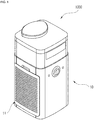
- a powerless humidification module for an air cleaner capable of preventing leakage of water (hereinafter, simply referred to as a 'humidification module') according to the present invention, as illustrated in FIG. 1 , is a powerless humidification module 1000 that may be attached to and detached from an upper portion of the body of an air cleaner 10 to humidify air that is suctioned through a suction hole 11 of the air cleaner, is purified, and is discharged to the upper side.
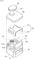
- the powerless humidification module 1000 includes a base cover 100, a cistern part 200, a humidification filter 250, and a protector 300.
- the base cover 100 may be located to be attached to and detached from the upper side of the air cleaner 10 and may have a first opening 110 and a second opening 120, and a cover part 400 that covers the opened upper portion of the base cover 100 may be located in the base cover 100.
- the opening 110 is located on the lower side of the base cover 100 and is opened toward an air discharge part (not illustrated) formed on the upper side of the air cleaner 100, and thus the air discharged from the upper side of the air cleaner 10 is introduced through the first opening 110.
- the second opening 120 is opened toward one side surface of the first cover 100, that is, a side surface of the first opening 110, and the air introduced from the air cleaner through the first opening 110 is discharged to the outside through the second opening 120.
- the cistern part 200 is located inside the base cover 100, and water is supplied to one side of the cistern part 200.
- the cistern part 200 has a space between partition walls 210a and 210b having predetermined heights such that the supplied water is stored, and the formed space is located to surround a periphery of the first opening 110.
- an overflow recess 211 formed to be recessed is formed on one side of an outer partition wall 21 0b of the cistern part 200.
- a water tank 500 may be provided on one side of the cistern part 200 through a through-hole 410 formed in the cover part 400 such that the water accommodated in the water tank 500 is supplied to one side of the cistern part 200, but the present invention is not limited thereto and, for example, water may be supplied directly to one side of the cistern part 200 through the through hole 410.
- an injection cap 510 installed in an entrance of the water tank 500 may be provided.
- the humidification filter 250 is located in the second opening 120 of the base cover 100.
- a lower side of the humidification filter 250 is inserted into a space formed on the side of the second opening 120 of the cistern part 200, and includes a material that can absorb and contain the water.
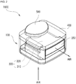
- the lower side of the humidification filter 250 is immersed in the water supplied to the cistern part 200, and humidification is performed as the air discharged from the air cleaner 10 and introduced through the first opening 110 is discharged to the outside through the second opening 120 in a state in which the humidity of the air is increased while the air passes through the humidification filter 250 immersed in the water (see FIG. 2 ).
- the water supplied to the cistern part 200 can be prevented from being introduced into the air cleaner 10 through the discharge part of the air cleaner 10 by disposing the cistern part 200, in which the space to which water is supplied is formed between the partition walls 210a and 210b, surrounds the circumference of the first opening 110 communicated with the discharge part, through which the air is discharged from the air cleaner 10.
- a partition wall 220 may be provided in the cistern part 200.
- a plurality of partition walls 220 are formed to have a predetermined height such that the space of the cistern part 200, in which the water is stored, is divided into two parts, and accordingly, the space of the cistern part 200 is divided into one side space 230 and an opposite side space 240 and the part in which the water is supplied and the humidification filter 250 are located in the one side space 230.
- a recessed overflow recess 221 is formed in the partition wall 220.
- the humidification filter 250 is immersed in the water supplied to the one side space 230 of the cistern part 200, and if the water supplied to the one side space 230 exceeds the height of the overflow recess 221 located in the partition wall 220, the water overflows the partition wall 220 through the overflow recess 221 and is introduced into the opposite side space 240 of the cistern part 200.
- the water supplied to the cistern part 200 can be prevented from being introduced into the interior of the air cleaner 10 and the water level of a part in which the humidification filter 250 is immersed can be constantly adjusted.
- the protector 300 is located inside the base cover 100 to communicate the first opening 110 and the second opening 120 formed in the base cover 100, and is located to cover an upper side of the first opening 110 through the upper prevention wall 310 located on the upper side of the first opening 110.
- the upper prevention wall 310 is spaced apart from the first opening 110 by a predetermined interval to cover the upper side of the first opening 110, and the first opening 110 and the second opening 120 are located to communicate with each other.
- the water leaked from the opened injection hole located below the water tank 500 or the water directly supplied from the upper side of the humidification module 100 may be introduced into the air cleaner 10 through the first opening 110, and because the protector 300 is provided, the water can be prevented from being introduced into the interior of the air cleaner 10 when the water tank 500 is coupled or water is directly supplied.
- the protector 300 includes a guide wall 320 that extends from an outer periphery of the upper prevention wall 310 to the lower side.
- the guide wall 320 extends from the outer periphery of the upper prevention wall 310 to the space of the cistern part 200, to which the water is supplied.
- the guide wall 320 extends from an outer periphery of the upper prevention wall 310 to the lower side, and extends continuously with the space of the cistern part 200, in detail, the inner partition wall 210a of the cistern part 200.
- the introduction of the water leaked in the upper prevention wall 310 can be prevented by the upper prevention wall 310 and the introduction of the water into the air cleaner 10 can be prevented by the cistern part 200 as well, and the leaked water can be introduced into the cistern part 200 along the guide wall 320 to be used for humidification through the humidification filter 250.
- the guide wall 320 may extend from an outer periphery of the upper prevention wall 310, except for the second opening 120, to be continuous with the inner partition wall 210a that defines the space of the cistern part 200.
- the flows of the air through the second opening 120 can be made smoother, and a portion of the leaked water can be directly absorbed by the humidification filter 250 to be used for humidification.
- a drain hole 130 may be formed on one side of the base cover 100.
- the drain hole 130 is formed by opening a lower portion of one side of the base cover 100, and if the supplied water overflows the height of the overflow recess 211 formed in the outer partition wall 210b of the cistern part 200 and is introduced, the overflowing water overflows the outer partition wall 21 0b and flows between the inner peripheral surface of the base cover 100 and the outer partition wall 21 0b of the cistern part 200 through the overflow recess 211 and is discharged to the humidification module 1000 through the drain hole 130.
- the partition wall 220 is provided in the cistern part 200 to divide the space of the cistern part 200, and if the water introduced from one side of the cistern part 200 into the opposite side space 240 of the cistern part 200 after overflowing the partition wall 220 overflows the height of the overflow recess 211 formed in the outer partition wall 21 0b, the overflowing water flows to the base cover 100, after overflowing the outer partition wall 210b through the overflow recess 211 and is discharged through the drain hole 130 (see the arrow of FIG. 5 ).
- the water in the cistern part 200 can be prevented from being introduced into the interior of the air cleaner 10 by two stages.
- a sensor that detects the level of the water stored in the space of the cistern part 200 is further provided, and if the water introduced into the space of the cistern part 200 is detected to be a predetermined height or more, it may be displayed through a display unit (not illustrated) connected to the sensor.
- an opening/closing unit (not illustrated) may be provided on the side of the drain hole 130, and if the sensor detects that the level of the water is a predetermined height or more, the opening/closing unit can be opened such that the water introduced to the base cover 100, after overflowing the outer partition wall 210b of the cistern part 200 can be discharged.
- the powerless humidification module for an air cleaner that may prevent leakage of water according to the present invention
- overflowing of water into the interior of the air cleaner and introduction of water when the water is supplied can be prevented, a predetermined amount of water that is necessary for humidification can be adjusted, and the humidification module can be easily attached to and detached from the air cleaner.
Landscapes
- Engineering & Computer Science (AREA)
- Chemical & Material Sciences (AREA)
- Combustion & Propulsion (AREA)
- Mechanical Engineering (AREA)
- General Engineering & Computer Science (AREA)
- Dispersion Chemistry (AREA)
- Air Humidification (AREA)
Abstract
Description
- The present invention relates to a humidification module, and more particularly to a powerless humidification module for an air cleaner which is installed in an air cleaner and is capable of preventing leakage of water into the air cleaner.
- An air cleaner having a general humidification function can perform air purification and humidification by using an air purification filter and a humidification unit installed in the interior of a device.
- However, according to a humidification cleaner of a conventional technology, when a humidification function is not used, a humidification filter installed in the interior of the device has to be separated, and thus it is bothersome to use the humidification cleaner and the size of the device increases as the number of parts installed in the interior of the device increases.
- Further, because the humidification cleaner of the conventional technology is disposed in the interior of the device, the humidified air is supplied to the interior via the interior of the device and thus the humidification degree is low.
- In an effort to solve the above-described problems, in patent document 1 of the applicant discloses a powerless humidification device for an air cleaner that can be separated from an air cleaner without being integrally formed with the air cleaner and can be mounted on various kinds of air cleaners with a simple structure.
- The humidification device may be easily mounted on various types of air cleaners and thus may humidifies an interior by using air discharged from the air cleaner without using a separate power supply, but water in the interior of the humidification device may be introduced into the air cleaner as the humidification device is detachably mounted on the air cleaner.
- When the water leaked from the humidification device is introduced into the interior of the air cleaner, the electric parts located in the interior of the air cleaner may break down and a short circuit accident may occur according to occasions, and it may be considered that a waterproof member, such as rubber, is interposed in an attachment/detachment part to prevent the problem, but the waterproof member formed of a material such as rubber may deteriorate the easiness of attachment of the humidification module
(Patent Document 1) Patent document 1:KR 2017-0043314 A - The present invention has been made in an effort to overcome the above-described problems, and provides a powerless humidification module for an air cleaner that may prevent leakage of water into an air cleaner.
- In accordance with an aspect of the present invention, there is provided a powerless humidification module for an air cleaner which is detachably mounted on an upper portion of a body of the air cleaner and is capable of preventing leakage of water, humidification module including: a base cover having a first opening opened toward the air cleaner and a second opening opened toward a side surface of the first opening; a cistern part located in the interior of the base cover and located such that a space defined between an inner partition wall and an outer partition wall having predetermined heights such that water supplied to one side thereof is stored surrounds a periphery of the first opening whereby water supplied to one side thereof is stored; and a humidification filter located in the second opening.
- The humidification module may further include a protector located in the interior of the base cover to communicate the first opening and the second opening and located to cover an upper portion of the first opening.
- The protector may include: an upper prevention wall located to cover the upper portion of the first opening; and a guide wall extending from an outer periphery of the upper prevention wall to the space of the cistern part.
- The humidification module may further include a drain hole formed on one side of the base cover, and when the water supplied to one side space of the cistern part overflows a predetermined height of an overflow recess formed in the outer partition wall, the water may be discharged through the drain hole, overflowing the outer partition wall through the overflow recess.
- The humidification module may further include a partition wall which has a height such that the space, in which the water of the cistern part is stored, is divided into one side space and an opposite side space, and when the water supplied to one side space of the cistern part overflows a predetermined height of an overflow recess formed in the partition wall, the water may be introduced into the opposite side space of the cistern part, overflowing the partition wall through the overflow recess.
- The humidification module may further include a drain hole formed on one side of the base cover, and when the water introduced to the opposite side space of the cistern part overflows a predetermined height of an overflow recess formed in the outer partition wall, the water may be discharged through the drain hole overflowing the outer partition wall through the overflow recess.
- The humidification module may further include a sensor configured to detect the level of the water stored in the space of the cistern part.
- According to the powerless humidification module for an air cleaner that may prevent leakage of water according to the present invention, overflowing of water into the interior of the air cleaner and introduction of water when the water is supplied can be prevented, a predetermined amount of water that is necessary for humidification can be adjusted, and the humidification module can be easily attached to and detached from the air cleaner.
-
-
FIG. 1 is a perspective view illustrating a state in which a powerless humidification module for an air cleaner capable of preventing leakage of water is installed in an air cleaner according to an embodiment of the present invention; -
FIG. 2 is a perspective view of a powerless humidification module for an air cleaner capable of preventing leakage of water according to an embodiment of the present invention; -
FIG. 3 is an exploded perspective view of the powerless humidification module for an air cleaner capable of preventing leakage of water according to the embodiment of the present invention; -
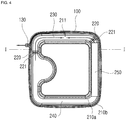
FIG. 4 is a plan view illustrating a base cover and a cistern part of the powerless humidification module for an air cleaner capable of preventing leakage of water according to the present invention, when viewed from the top; and -
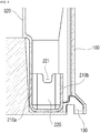
FIG. 5 is a sectional view taken along a line I-I ofFIG. 4 . - The objectives, features, and other advantages of the present invention will be more apparent by describing exemplary embodiments of the present invention in detail with reference to the accompanying drawings. It should be noted that the drawings are not to precise scale and may be exaggerated in thickness of lines or size of components for descriptive convenience and clarity. In addition, the terms used herein are defined by taking functions of the present invention into account and can be changed according to user or operator custom or intention. Therefore, definition of the terms should be made according to the overall disclosure set forth herein.
- Further, the embodiments are provided exemplarily for description of the present invention, and are not intended to limit the technical scope of the present invention.
- The elements constituting the humidification module capable of preventing leakage of water of an air cleaner according to the present invention may be integrally used or separately used as occasion demands. Further, some elements may be omitted according to the usage of the humidification module.
- Hereinafter, a humidification module for an air cleaner capable of preventing leakage of water according to an embodiment of the present invention will be described in detail with reference to
FIGS. 1 to 5 . - A powerless humidification module for an air cleaner capable of preventing leakage of water (hereinafter, simply referred to as a 'humidification module') according to the present invention, as illustrated in
FIG. 1 , is apowerless humidification module 1000 that may be attached to and detached from an upper portion of the body of anair cleaner 10 to humidify air that is suctioned through asuction hole 11 of the air cleaner, is purified, and is discharged to the upper side. - As illustrated in
FIGS. 2 and3 , thepowerless humidification module 1000 according to the embodiment of the present invention includes abase cover 100, acistern part 200, ahumidification filter 250, and aprotector 300. - The
base cover 100 may be located to be attached to and detached from the upper side of theair cleaner 10 and may have afirst opening 110 and a second opening 120, and acover part 400 that covers the opened upper portion of thebase cover 100 may be located in thebase cover 100. - The
opening 110 is located on the lower side of thebase cover 100 and is opened toward an air discharge part (not illustrated) formed on the upper side of theair cleaner 100, and thus the air discharged from the upper side of theair cleaner 10 is introduced through thefirst opening 110. - The
second opening 120 is opened toward one side surface of thefirst cover 100, that is, a side surface of thefirst opening 110, and the air introduced from the air cleaner through thefirst opening 110 is discharged to the outside through thesecond opening 120. - The
cistern part 200 is located inside thebase cover 100, and water is supplied to one side of thecistern part 200. - The
cistern part 200 has a space betweenpartition walls first opening 110. - Further, an
overflow recess 211 formed to be recessed is formed on one side of an outer partition wall 21 0b of thecistern part 200. - A
water tank 500 may be provided on one side of thecistern part 200 through a through-hole 410 formed in thecover part 400 such that the water accommodated in thewater tank 500 is supplied to one side of thecistern part 200, but the present invention is not limited thereto and, for example, water may be supplied directly to one side of thecistern part 200 through the throughhole 410. - When water is supplied to one side of the
cistern part 200 through thewater tank 500, aninjection cap 510 installed in an entrance of thewater tank 500 may be provided. - The
humidification filter 250 is located in the second opening 120 of thebase cover 100. In detail, a lower side of thehumidification filter 250 is inserted into a space formed on the side of the second opening 120 of thecistern part 200, and includes a material that can absorb and contain the water. - Accordingly, the lower side of the
humidification filter 250 is immersed in the water supplied to thecistern part 200, and humidification is performed as the air discharged from theair cleaner 10 and introduced through thefirst opening 110 is discharged to the outside through the second opening 120 in a state in which the humidity of the air is increased while the air passes through thehumidification filter 250 immersed in the water (seeFIG. 2 ). - In this way, the water supplied to the
cistern part 200 can be prevented from being introduced into theair cleaner 10 through the discharge part of theair cleaner 10 by disposing thecistern part 200, in which the space to which water is supplied is formed between thepartition walls first opening 110 communicated with the discharge part, through which the air is discharged from theair cleaner 10. - Further, as illustrated in
FIG. 4 , apartition wall 220 may be provided in thecistern part 200. A plurality ofpartition walls 220 are formed to have a predetermined height such that the space of thecistern part 200, in which the water is stored, is divided into two parts, and accordingly, the space of thecistern part 200 is divided into oneside space 230 and anopposite side space 240 and the part in which the water is supplied and thehumidification filter 250 are located in the oneside space 230. - Further, a
recessed overflow recess 221 is formed in thepartition wall 220. - Accordingly, the
humidification filter 250 is immersed in the water supplied to the oneside space 230 of thecistern part 200, and if the water supplied to the oneside space 230 exceeds the height of theoverflow recess 221 located in thepartition wall 220, the water overflows thepartition wall 220 through theoverflow recess 221 and is introduced into theopposite side space 240 of thecistern part 200. - Accordingly, the water supplied to the
cistern part 200 can be prevented from being introduced into the interior of theair cleaner 10 and the water level of a part in which thehumidification filter 250 is immersed can be constantly adjusted. - The
protector 300 is located inside thebase cover 100 to communicate thefirst opening 110 and the second opening 120 formed in thebase cover 100, and is located to cover an upper side of thefirst opening 110 through theupper prevention wall 310 located on the upper side of thefirst opening 110. - That is, the
upper prevention wall 310 is spaced apart from thefirst opening 110 by a predetermined interval to cover the upper side of thefirst opening 110, and the first opening 110 and thesecond opening 120 are located to communicate with each other. - In this way, when the
water tank 500 is installed from the upper side of thehumidification module 1000 to thecistern part 200, the water leaked from the opened injection hole located below thewater tank 500 or the water directly supplied from the upper side of thehumidification module 100 may be introduced into theair cleaner 10 through thefirst opening 110, and because theprotector 300 is provided, the water can be prevented from being introduced into the interior of theair cleaner 10 when thewater tank 500 is coupled or water is directly supplied. - Further, the
protector 300 includes aguide wall 320 that extends from an outer periphery of theupper prevention wall 310 to the lower side. - The
guide wall 320 extends from the outer periphery of theupper prevention wall 310 to the space of thecistern part 200, to which the water is supplied. - In detail, the
guide wall 320 extends from an outer periphery of theupper prevention wall 310 to the lower side, and extends continuously with the space of thecistern part 200, in detail, theinner partition wall 210a of thecistern part 200. - Accordingly, as descried above, the introduction of the water leaked in the
upper prevention wall 310 can be prevented by theupper prevention wall 310 and the introduction of the water into theair cleaner 10 can be prevented by thecistern part 200 as well, and the leaked water can be introduced into thecistern part 200 along theguide wall 320 to be used for humidification through thehumidification filter 250. - Further, the
guide wall 320 may extend from an outer periphery of theupper prevention wall 310, except for thesecond opening 120, to be continuous with theinner partition wall 210a that defines the space of thecistern part 200. - Accordingly, the flows of the air through the
second opening 120 can be made smoother, and a portion of the leaked water can be directly absorbed by thehumidification filter 250 to be used for humidification. - As illustrated in
FIGS. 4 and5 , adrain hole 130 may be formed on one side of thebase cover 100. - The
drain hole 130 is formed by opening a lower portion of one side of thebase cover 100, and if the supplied water overflows the height of theoverflow recess 211 formed in theouter partition wall 210b of thecistern part 200 and is introduced, the overflowing water overflows the outer partition wall 21 0b and flows between the inner peripheral surface of thebase cover 100 and the outer partition wall 21 0b of thecistern part 200 through theoverflow recess 211 and is discharged to thehumidification module 1000 through thedrain hole 130. - Further, when the
partition wall 220 is provided in thecistern part 200 to divide the space of thecistern part 200, and if the water introduced from one side of thecistern part 200 into theopposite side space 240 of thecistern part 200 after overflowing thepartition wall 220 overflows the height of theoverflow recess 211 formed in the outer partition wall 21 0b, the overflowing water flows to thebase cover 100, after overflowing theouter partition wall 210b through theoverflow recess 211 and is discharged through the drain hole 130 (see the arrow ofFIG. 5 ). - Accordingly, the water in the
cistern part 200 can be prevented from being introduced into the interior of theair cleaner 10 by two stages. - Further, a sensor (not illustrated) that detects the level of the water stored in the space of the
cistern part 200 is further provided, and if the water introduced into the space of thecistern part 200 is detected to be a predetermined height or more, it may be displayed through a display unit (not illustrated) connected to the sensor. - Meanwhile, an opening/closing unit (not illustrated) may be provided on the side of the
drain hole 130, and if the sensor detects that the level of the water is a predetermined height or more, the opening/closing unit can be opened such that the water introduced to thebase cover 100, after overflowing theouter partition wall 210b of thecistern part 200 can be discharged. - As described above, according to the powerless humidification module for an air cleaner that may prevent leakage of water according to the present invention, overflowing of water into the interior of the air cleaner and introduction of water when the water is supplied can be prevented, a predetermined amount of water that is necessary for humidification can be adjusted, and the humidification module can be easily attached to and detached from the air cleaner.
- Although the preferred embodiments of the present invention have been described, the present invention is not limited to the embodiments. That is, it should be understood that an ordinary person in the art to which the present invention pertains can variously change and modify the present invention without departing from the spirit and scope of the claims and all the changes and equivalents also fall within the scope of the present invention.
-
- 10:
- air cleaner
- 100:
- base cover
- 110:
- first opening
- 120:
- second opening
- 200:
- cistern part
- 210a, 210b:
- partition wall
- 220:
- partition wall
- 300:
- protector
- 310:
- upper prevention wall
- 320:
- guide wall
- 400:
- cover
- 500:
- water tank
Claims (7)
- A powerless humidification module for an air cleaner which is detachably mounted on an upper portion of a body of the air cleaner and is capable of preventing leakage of water, humidification module comprising:a base cover having a first opening opened toward the air cleaner and a second opening opened toward a side surface of the first opening;a cistern part located in the interior of the base cover and located such that a space defined between an inner partition wall and an outer partition wall having predetermined heights such that water supplied to one side thereof is stored surrounds a periphery of the first opening whereby water supplied to one side thereof is stored; and
a humidification filter located in the second opening. - The humidification module of claim 1, further comprising:
a protector located in the interior of the base cover to communicate the first opening and the second opening and located to cover an upper portion of the first opening. - The humidification module of claim 2, wherein the protector comprises:an upper prevention wall located to cover the upper portion of the first opening; anda guide wall extending from an outer periphery of the upper prevention wall to the space of the cistern part.
- The humidification module of claim 1, further comprising:a drain hole formed on one side of the base cover,wherein when the water supplied to one side space of the cistern part overflows a predetermined height of an overflow recess formed in the outer partition wall, the water is discharged through the drain hole, overflowing the outer partition wall through the overflow recess.
- The humidification module of claim 1, further comprising:a partition wall which has a height such that the space, in which the water of the cistern part is stored, is divided into one side space and an opposite side space,wherein when the water supplied to one side space of the cistern part overflows a predetermined height of an overflow recess formed in the partition wall, the water is introduced into the opposite side space of the cistern part, overflowing the partition wall through the overflow recess.
- The humidification module of claim 5, further comprising:a drain hole formed on one side of the base cover,wherein when the water introduced to the opposite side space of the cistern part overflows a predetermined height of an overflow recess formed in the outer partition wall, the water is discharged through the drain hole overflowing the outer partition wall through the overflow recess.
- The humidification module of any one of claims 1 to 6, further comprising:
a sensor configured to detect the level of the water stored in the space of the cistern part.
Applications Claiming Priority (2)
| Application Number | Priority Date | Filing Date | Title |
|---|---|---|---|
| KR1020170086609A KR102037505B1 (en) | 2017-07-07 | 2017-07-07 | Non-power source type Humidifying module capable of prevent leaking water for air cleaner |
| PCT/KR2018/007572 WO2019009614A1 (en) | 2017-07-07 | 2018-07-04 | Water leak-preventing non-powered humidifying module for air purifier |
Publications (4)
| Publication Number | Publication Date |
|---|---|
| EP3650766A1 true EP3650766A1 (en) | 2020-05-13 |
| EP3650766A4 EP3650766A4 (en) | 2021-03-10 |
| EP3650766B1 EP3650766B1 (en) | 2024-08-28 |
| EP3650766C0 EP3650766C0 (en) | 2024-08-28 |
Family
ID=64950172
Family Applications (1)
| Application Number | Title | Priority Date | Filing Date |
|---|---|---|---|
| EP18827940.0A Active EP3650766B1 (en) | 2017-07-07 | 2018-07-04 | Water leak-preventing non-powered humidifying module for air purifier |
Country Status (6)
| Country | Link |
|---|---|
| US (1) | US11598541B2 (en) |
| EP (1) | EP3650766B1 (en) |
| JP (1) | JP6927477B2 (en) |
| KR (1) | KR102037505B1 (en) |
| CN (1) | CN110869678B (en) |
| WO (1) | WO2019009614A1 (en) |
Families Citing this family (4)
| Publication number | Priority date | Publication date | Assignee | Title |
|---|---|---|---|---|
| KR102770051B1 (en) | 2019-12-10 | 2025-02-21 | 삼성전자주식회사 | Humidifier |
| US12270567B2 (en) * | 2020-08-31 | 2025-04-08 | Dirk Niedermann | Portable air treatment apparatus |
| USD921864S1 (en) * | 2020-11-05 | 2021-06-08 | Shenzhen Vantop Technology & Innovation Co., Ltd. | Humidifier |
| USD921869S1 (en) * | 2021-01-12 | 2021-06-08 | Zhongtao Han | Air purifier |
Family Cites Families (22)
| Publication number | Priority date | Publication date | Assignee | Title |
|---|---|---|---|---|
| JPS61134531A (en) * | 1984-12-03 | 1986-06-21 | Mitsubishi Electric Corp | Wall hunging type humidifier device |
| US5578113A (en) * | 1994-07-19 | 1996-11-26 | Holmes Product Corp. | Air treatment system |
| JP3770513B2 (en) * | 1997-08-22 | 2006-04-26 | 株式会社前川製作所 | Humidified air production equipment |
| US20020070465A1 (en) * | 2000-12-07 | 2002-06-13 | Harvel Gerald Stephen | Water conservation system for humidifiers |
| US7066452B2 (en) * | 2002-10-11 | 2006-06-27 | Honeywell International Inc. | Humidifier with reverse osmosis filter |
| CN2681018Y (en) * | 2003-12-12 | 2005-02-23 | 宋伟增 | Convectional moisture film humidifying equipment of radiator |
| CN2695841Y (en) * | 2004-05-19 | 2005-04-27 | 宋伟增 | Multifunctional convection radiator |
| KR100815593B1 (en) * | 2006-10-18 | 2008-03-20 | 김성일 | air cleaner |
| JP2009109720A (en) * | 2007-10-30 | 2009-05-21 | Konica Minolta Business Technologies Inc | Paper humidifier and image forming apparatus with the same |
| JP2011226670A (en) * | 2010-04-16 | 2011-11-10 | Panasonic Corp | Air cleaning equipment with humidifying function |
| KR101200085B1 (en) | 2010-09-10 | 2012-11-12 | 주식회사 콜러노비타 | Air cleaning humidifier and water amount control method |
| WO2012091369A2 (en) * | 2010-12-29 | 2012-07-05 | Woongjin Coway Co., Ltd | Humidification apparatus |
| KR101433288B1 (en) * | 2012-06-25 | 2014-08-25 | 주식회사 에스티 | indoor air control system have humidification function |
| JP6222600B2 (en) * | 2013-10-07 | 2017-11-01 | 静岡製機株式会社 | Humidifier leak prevention device |
| CN104315643B (en) * | 2014-07-03 | 2018-01-05 | 青岛海尔空调器有限总公司 | Humidifier and air handling system |
| KR102237457B1 (en) | 2014-08-28 | 2021-04-07 | 주식회사 위니아딤채 | Water supply type air washer |
| CN104566743B (en) * | 2014-12-31 | 2018-03-16 | 广东美的制冷设备有限公司 | Vertical air eliminator humidifying structure and vertical air eliminator |
| CN104879838B (en) * | 2015-04-30 | 2018-02-02 | 余旦 | A kind of air processor with multiple-working mode |
| CN104990137A (en) | 2015-05-28 | 2015-10-21 | 广东美的制冷设备有限公司 | Air channel of air purification and humidification device and air purification and humidification device |
| KR102502946B1 (en) | 2015-10-13 | 2023-02-23 | 코웨이 주식회사 | Humidifier without power source for air cleaner |
| KR20170051249A (en) * | 2015-10-30 | 2017-05-11 | 엘지전자 주식회사 | apparatus for both humidification and air cleaning |
| CN106871304B (en) * | 2017-04-06 | 2022-10-28 | 深圳市康弘智能健康科技股份有限公司 | Humidification structure and air purification device |
-
2017
- 2017-07-07 KR KR1020170086609A patent/KR102037505B1/en active Active
-
2018
- 2018-07-04 WO PCT/KR2018/007572 patent/WO2019009614A1/en not_active Ceased
- 2018-07-04 CN CN201880045572.8A patent/CN110869678B/en active Active
- 2018-07-04 US US16/628,748 patent/US11598541B2/en active Active
- 2018-07-04 EP EP18827940.0A patent/EP3650766B1/en active Active
- 2018-07-04 JP JP2020500632A patent/JP6927477B2/en active Active
Also Published As
| Publication number | Publication date |
|---|---|
| JP6927477B2 (en) | 2021-09-01 |
| US20200284454A1 (en) | 2020-09-10 |
| US11598541B2 (en) | 2023-03-07 |
| CN110869678B (en) | 2021-07-27 |
| WO2019009614A1 (en) | 2019-01-10 |
| EP3650766A4 (en) | 2021-03-10 |
| CN110869678A (en) | 2020-03-06 |
| KR102037505B1 (en) | 2019-11-29 |
| EP3650766B1 (en) | 2024-08-28 |
| EP3650766C0 (en) | 2024-08-28 |
| KR20190005640A (en) | 2019-01-16 |
| JP2020526730A (en) | 2020-08-31 |
Similar Documents
| Publication | Publication Date | Title |
|---|---|---|
| EP3650766B1 (en) | Water leak-preventing non-powered humidifying module for air purifier | |
| SE519579C2 (en) | Liquid container with straw arranged therein | |
| US20240299145A1 (en) | Portable oral irrigator | |
| KR20170008324A (en) | Suction machine comprising a housing made of expanded plastic material | |
| JP6282995B2 (en) | Humidifier | |
| JP2010192243A (en) | Switch device | |
| JP2010167052A (en) | Breast pump for mother's milk | |
| CN217937922U (en) | Detachable water purifying dispenser of pure water case | |
| CN113864937A (en) | Humidifier | |
| CN217548744U (en) | Float type oxygen inhalator | |
| CN217763750U (en) | Display window leak protection water installation and humidifier | |
| CN210272119U (en) | Box and waterproof switch box at bottom of switch | |
| CN114082068B (en) | Humidification tank | |
| CN214387302U (en) | Liquid automatic dispensing device | |
| CN208850025U (en) | A bluetooth speaker | |
| JP2008106593A (en) | Automatic faucet | |
| CN224024007U (en) | Atomizing cup | |
| CN224070812U (en) | Positive and negative pressure nose washing device | |
| CN218395044U (en) | Ultrasonic cleaning structure and counter basin | |
| CN220846726U (en) | Display module assembly and clothing treatment facility | |
| CN213526914U (en) | Stock solution equipment and have its oral nebulizer with leak protection function | |
| CN218943063U (en) | Food processor with good waterproof effect | |
| CN223392707U (en) | Portable medical vacuum negative pressure drainage machine | |
| CN201609044U (en) | Waterproof mower | |
| CN215082035U (en) | Medicine box underlying structure of foot bath device and foot bath device |
Legal Events
| Date | Code | Title | Description |
|---|---|---|---|
| STAA | Information on the status of an ep patent application or granted ep patent |
Free format text: STATUS: THE INTERNATIONAL PUBLICATION HAS BEEN MADE |
|
| PUAI | Public reference made under article 153(3) epc to a published international application that has entered the european phase |
Free format text: ORIGINAL CODE: 0009012 |
|
| STAA | Information on the status of an ep patent application or granted ep patent |
Free format text: STATUS: REQUEST FOR EXAMINATION WAS MADE |
|
| 17P | Request for examination filed |
Effective date: 20200109 |
|
| AK | Designated contracting states |
Kind code of ref document: A1 Designated state(s): AL AT BE BG CH CY CZ DE DK EE ES FI FR GB GR HR HU IE IS IT LI LT LU LV MC MK MT NL NO PL PT RO RS SE SI SK SM TR |
|
| AX | Request for extension of the european patent |
Extension state: BA ME |
|
| DAV | Request for validation of the european patent (deleted) | ||
| DAX | Request for extension of the european patent (deleted) | ||
| A4 | Supplementary search report drawn up and despatched |
Effective date: 20210210 |
|
| RIC1 | Information provided on ipc code assigned before grant |
Ipc: F24F 6/04 20060101ALI20210204BHEP Ipc: F24F 6/00 20060101ALI20210204BHEP Ipc: F24F 11/89 20180101ALI20210204BHEP Ipc: F24F 3/16 20210101ALI20210204BHEP Ipc: F24F 11/00 20180101ALI20210204BHEP Ipc: F24F 13/20 20060101ALI20210204BHEP Ipc: F24F 6/12 20060101AFI20210204BHEP Ipc: F24F 8/00 20210101ALI20210204BHEP |
|
| STAA | Information on the status of an ep patent application or granted ep patent |
Free format text: STATUS: EXAMINATION IS IN PROGRESS |
|
| 17Q | First examination report despatched |
Effective date: 20230316 |
|
| REG | Reference to a national code |
Ref legal event code: R079 Ref country code: DE Ref legal event code: R079 Ref document number: 602018073722 Country of ref document: DE Free format text: PREVIOUS MAIN CLASS: F24F0006120000 Ipc: F24F0008117000 |
|
| GRAP | Despatch of communication of intention to grant a patent |
Free format text: ORIGINAL CODE: EPIDOSNIGR1 |
|
| STAA | Information on the status of an ep patent application or granted ep patent |
Free format text: STATUS: GRANT OF PATENT IS INTENDED |
|
| RIC1 | Information provided on ipc code assigned before grant |
Ipc: F24F 6/00 20060101ALI20240206BHEP Ipc: F24F 11/89 20180101ALI20240206BHEP Ipc: F24F 6/04 20060101ALI20240206BHEP Ipc: F24F 8/00 20210101ALI20240206BHEP Ipc: F24F 13/20 20060101ALI20240206BHEP Ipc: F24F 8/117 20210101AFI20240206BHEP |
|
| INTG | Intention to grant announced |
Effective date: 20240220 |
|
| GRAS | Grant fee paid |
Free format text: ORIGINAL CODE: EPIDOSNIGR3 |
|
| GRAA | (expected) grant |
Free format text: ORIGINAL CODE: 0009210 |
|
| STAA | Information on the status of an ep patent application or granted ep patent |
Free format text: STATUS: THE PATENT HAS BEEN GRANTED |
|
| AK | Designated contracting states |
Kind code of ref document: B1 Designated state(s): AL AT BE BG CH CY CZ DE DK EE ES FI FR GB GR HR HU IE IS IT LI LT LU LV MC MK MT NL NO PL PT RO RS SE SI SK SM TR |
|
| REG | Reference to a national code |
Ref country code: GB Ref legal event code: FG4D |
|
| REG | Reference to a national code |
Ref country code: CH Ref legal event code: EP |
|
| REG | Reference to a national code |
Ref country code: DE Ref legal event code: R096 Ref document number: 602018073722 Country of ref document: DE |
|
| REG | Reference to a national code |
Ref country code: IE Ref legal event code: FG4D |
|
| U01 | Request for unitary effect filed |
Effective date: 20240927 |
|
| U07 | Unitary effect registered |
Designated state(s): AT BE BG DE DK EE FI FR IT LT LU LV MT NL PT RO SE SI Effective date: 20241024 |
|
| PG25 | Lapsed in a contracting state [announced via postgrant information from national office to epo] |
Ref country code: NO Free format text: LAPSE BECAUSE OF FAILURE TO SUBMIT A TRANSLATION OF THE DESCRIPTION OR TO PAY THE FEE WITHIN THE PRESCRIBED TIME-LIMIT Effective date: 20241128 |
|
| PG25 | Lapsed in a contracting state [announced via postgrant information from national office to epo] |
Ref country code: GR Free format text: LAPSE BECAUSE OF FAILURE TO SUBMIT A TRANSLATION OF THE DESCRIPTION OR TO PAY THE FEE WITHIN THE PRESCRIBED TIME-LIMIT Effective date: 20241129 Ref country code: PL Free format text: LAPSE BECAUSE OF FAILURE TO SUBMIT A TRANSLATION OF THE DESCRIPTION OR TO PAY THE FEE WITHIN THE PRESCRIBED TIME-LIMIT Effective date: 20240828 |
|
| PG25 | Lapsed in a contracting state [announced via postgrant information from national office to epo] |
Ref country code: IS Free format text: LAPSE BECAUSE OF FAILURE TO SUBMIT A TRANSLATION OF THE DESCRIPTION OR TO PAY THE FEE WITHIN THE PRESCRIBED TIME-LIMIT Effective date: 20241228 |
|
| PG25 | Lapsed in a contracting state [announced via postgrant information from national office to epo] |
Ref country code: HR Free format text: LAPSE BECAUSE OF FAILURE TO SUBMIT A TRANSLATION OF THE DESCRIPTION OR TO PAY THE FEE WITHIN THE PRESCRIBED TIME-LIMIT Effective date: 20240828 |
|
| PG25 | Lapsed in a contracting state [announced via postgrant information from national office to epo] |
Ref country code: RS Free format text: LAPSE BECAUSE OF FAILURE TO SUBMIT A TRANSLATION OF THE DESCRIPTION OR TO PAY THE FEE WITHIN THE PRESCRIBED TIME-LIMIT Effective date: 20241128 Ref country code: ES Free format text: LAPSE BECAUSE OF FAILURE TO SUBMIT A TRANSLATION OF THE DESCRIPTION OR TO PAY THE FEE WITHIN THE PRESCRIBED TIME-LIMIT Effective date: 20240828 |
|
| PG25 | Lapsed in a contracting state [announced via postgrant information from national office to epo] |
Ref country code: RS Free format text: LAPSE BECAUSE OF FAILURE TO SUBMIT A TRANSLATION OF THE DESCRIPTION OR TO PAY THE FEE WITHIN THE PRESCRIBED TIME-LIMIT Effective date: 20241128 Ref country code: PL Free format text: LAPSE BECAUSE OF FAILURE TO SUBMIT A TRANSLATION OF THE DESCRIPTION OR TO PAY THE FEE WITHIN THE PRESCRIBED TIME-LIMIT Effective date: 20240828 Ref country code: NO Free format text: LAPSE BECAUSE OF FAILURE TO SUBMIT A TRANSLATION OF THE DESCRIPTION OR TO PAY THE FEE WITHIN THE PRESCRIBED TIME-LIMIT Effective date: 20241128 Ref country code: IS Free format text: LAPSE BECAUSE OF FAILURE TO SUBMIT A TRANSLATION OF THE DESCRIPTION OR TO PAY THE FEE WITHIN THE PRESCRIBED TIME-LIMIT Effective date: 20241228 Ref country code: HR Free format text: LAPSE BECAUSE OF FAILURE TO SUBMIT A TRANSLATION OF THE DESCRIPTION OR TO PAY THE FEE WITHIN THE PRESCRIBED TIME-LIMIT Effective date: 20240828 Ref country code: GR Free format text: LAPSE BECAUSE OF FAILURE TO SUBMIT A TRANSLATION OF THE DESCRIPTION OR TO PAY THE FEE WITHIN THE PRESCRIBED TIME-LIMIT Effective date: 20241129 Ref country code: ES Free format text: LAPSE BECAUSE OF FAILURE TO SUBMIT A TRANSLATION OF THE DESCRIPTION OR TO PAY THE FEE WITHIN THE PRESCRIBED TIME-LIMIT Effective date: 20240828 |
|
| PG25 | Lapsed in a contracting state [announced via postgrant information from national office to epo] |
Ref country code: SM Free format text: LAPSE BECAUSE OF FAILURE TO SUBMIT A TRANSLATION OF THE DESCRIPTION OR TO PAY THE FEE WITHIN THE PRESCRIBED TIME-LIMIT Effective date: 20240828 |
|
| PG25 | Lapsed in a contracting state [announced via postgrant information from national office to epo] |
Ref country code: CZ Free format text: LAPSE BECAUSE OF FAILURE TO SUBMIT A TRANSLATION OF THE DESCRIPTION OR TO PAY THE FEE WITHIN THE PRESCRIBED TIME-LIMIT Effective date: 20240828 |
|
| PG25 | Lapsed in a contracting state [announced via postgrant information from national office to epo] |
Ref country code: SK Free format text: LAPSE BECAUSE OF FAILURE TO SUBMIT A TRANSLATION OF THE DESCRIPTION OR TO PAY THE FEE WITHIN THE PRESCRIBED TIME-LIMIT Effective date: 20240828 |
|
| PLBE | No opposition filed within time limit |
Free format text: ORIGINAL CODE: 0009261 |
|
| STAA | Information on the status of an ep patent application or granted ep patent |
Free format text: STATUS: NO OPPOSITION FILED WITHIN TIME LIMIT |
|
| 26N | No opposition filed |
Effective date: 20250530 |
|
| U20 | Renewal fee for the european patent with unitary effect paid |
Year of fee payment: 8 Effective date: 20250723 |
|
| REG | Reference to a national code |
Ref country code: CH Ref legal event code: H13 Free format text: ST27 STATUS EVENT CODE: U-0-0-H10-H13 (AS PROVIDED BY THE NATIONAL OFFICE) Effective date: 20260224 |
|
| GBPC | Gb: european patent ceased through non-payment of renewal fee |
Effective date: 20250704 |
|
| PG25 | Lapsed in a contracting state [announced via postgrant information from national office to epo] |
Ref country code: GB Free format text: LAPSE BECAUSE OF NON-PAYMENT OF DUE FEES Effective date: 20250704 |
|
| PG25 | Lapsed in a contracting state [announced via postgrant information from national office to epo] |
Ref country code: CH Free format text: LAPSE BECAUSE OF NON-PAYMENT OF DUE FEES Effective date: 20250731 |