EP3650735B1 - Gear paddle switch unit for triggering a gear shift in a vehicle - Google Patents
Gear paddle switch unit for triggering a gear shift in a vehicle Download PDFInfo
- Publication number
- EP3650735B1 EP3650735B1 EP19203450.2A EP19203450A EP3650735B1 EP 3650735 B1 EP3650735 B1 EP 3650735B1 EP 19203450 A EP19203450 A EP 19203450A EP 3650735 B1 EP3650735 B1 EP 3650735B1
- Authority
- EP
- European Patent Office
- Prior art keywords
- triggering
- steering wheel
- gear
- magnet
- switch unit
- Prior art date
- Legal status (The legal status is an assumption and is not a legal conclusion. Google has not performed a legal analysis and makes no representation as to the accuracy of the status listed.)
- Active
Links
Images


Classifications
-
- B—PERFORMING OPERATIONS; TRANSPORTING
- B60—VEHICLES IN GENERAL
- B60K—ARRANGEMENT OR MOUNTING OF PROPULSION UNITS OR OF TRANSMISSIONS IN VEHICLES; ARRANGEMENT OR MOUNTING OF PLURAL DIVERSE PRIME-MOVERS IN VEHICLES; AUXILIARY DRIVES FOR VEHICLES; INSTRUMENTATION OR DASHBOARDS FOR VEHICLES; ARRANGEMENTS IN CONNECTION WITH COOLING, AIR INTAKE, GAS EXHAUST OR FUEL SUPPLY OF PROPULSION UNITS IN VEHICLES
- B60K20/00—Arrangement or mounting of change-speed gearing control devices in vehicles
- B60K20/02—Arrangement or mounting of change-speed gearing control devices in vehicles of initiating means
- B60K20/06—Arrangement or mounting of change-speed gearing control devices in vehicles of initiating means mounted on steering column or the like
-
- B—PERFORMING OPERATIONS; TRANSPORTING
- B60—VEHICLES IN GENERAL
- B60K—ARRANGEMENT OR MOUNTING OF PROPULSION UNITS OR OF TRANSMISSIONS IN VEHICLES; ARRANGEMENT OR MOUNTING OF PLURAL DIVERSE PRIME-MOVERS IN VEHICLES; AUXILIARY DRIVES FOR VEHICLES; INSTRUMENTATION OR DASHBOARDS FOR VEHICLES; ARRANGEMENTS IN CONNECTION WITH COOLING, AIR INTAKE, GAS EXHAUST OR FUEL SUPPLY OF PROPULSION UNITS IN VEHICLES
- B60K20/00—Arrangement or mounting of change-speed gearing control devices in vehicles
- B60K20/02—Arrangement or mounting of change-speed gearing control devices in vehicles of initiating means
-
- F—MECHANICAL ENGINEERING; LIGHTING; HEATING; WEAPONS; BLASTING
- F16—ENGINEERING ELEMENTS AND UNITS; GENERAL MEASURES FOR PRODUCING AND MAINTAINING EFFECTIVE FUNCTIONING OF MACHINES OR INSTALLATIONS; THERMAL INSULATION IN GENERAL
- F16H—GEARING
- F16H59/00—Control inputs to control units of change-speed- or reversing-gearings for conveying rotary motion
- F16H59/02—Selector apparatus
-
- F—MECHANICAL ENGINEERING; LIGHTING; HEATING; WEAPONS; BLASTING
- F16—ENGINEERING ELEMENTS AND UNITS; GENERAL MEASURES FOR PRODUCING AND MAINTAINING EFFECTIVE FUNCTIONING OF MACHINES OR INSTALLATIONS; THERMAL INSULATION IN GENERAL
- F16H—GEARING
- F16H61/00—Control functions within control units of change-speed- or reversing-gearings for conveying rotary motion ; Control of exclusively fluid gearing, friction gearing, gearings with endless flexible members or other particular types of gearing
- F16H61/24—Providing feel, e.g. to enable selection
-
- F—MECHANICAL ENGINEERING; LIGHTING; HEATING; WEAPONS; BLASTING
- F16—ENGINEERING ELEMENTS AND UNITS; GENERAL MEASURES FOR PRODUCING AND MAINTAINING EFFECTIVE FUNCTIONING OF MACHINES OR INSTALLATIONS; THERMAL INSULATION IN GENERAL
- F16H—GEARING
- F16H59/00—Control inputs to control units of change-speed- or reversing-gearings for conveying rotary motion
- F16H59/02—Selector apparatus
- F16H2059/0239—Up- and down-shift or range or mode selection by repeated movement
- F16H2059/0247—Up- and down-shift or range or mode selection by repeated movement with lever or paddle behind steering wheel
Definitions
- the present invention relates to a gear paddle switch unit for triggering a gear shift in a vehicle.
- the present invention further relates to a gear paddle switch unit which comprises at least one steering wheel paddle which is designed for actuating a gear shift, wherein the unit provides an improved actuating response and a reduced time for performing a gear shift.
- a device for actuating a gear shift is a gear lever which is provided between the front seats.
- Such systems are well known in the art.
- a gear paddle switch unit is known for example from US 5 224 939 .
- the present invention provides a gear paddle switch unit for triggering a gear shift in a vehicle
- the gear paddle switch unit comprises a main body, and at least one steering wheel paddle with an actuation portion or actuating the steering wheel paddle by a user and an opposing triggering portion for triggering a gear shift
- the gear paddle switch unit further comprises a bearing for movably fixing the at least one steering wheel paddle such, that the triggering portion is pivotable relatively to the main body between a resting position and a triggering position, wherein the triggering portion is held in the resting position preloaded with a preload force caused by a triggering unit so that the triggering portion is moved from the triggering position to the resting position by said preload force after release of the steering wheel paddle by the user in the triggering position
- the triggering unit is configured for providing a magnetic force for preloading the triggering portion in the resting position for providing a haptic feedback to a user when actuating the steering wheel paddle.
- Such a gear paddle switch unit may provide improvements with regard to performing a gear shift in a vehicle with at least one of a fast gear shift, a reliable arrangement and an improved haptic response for the user of the vehicle.
- the present invention thus refers to a gear paddle switch unit for triggering a gear shift in a vehicle.
- the unit is configured for receiving instructions for a gear shift and in turn triggering the gear shift for example in an electronic matter.
- a mechanism may be activated which in turn performs the gear shift.
- the gear paddle switch unit is particularly suited for a vehicle, such as a car.
- the gear paddle switch unit comprises a main body.
- the main body may particularly a part which may support further parts of the unit, such as one or more gear shift paddles and may thus be a central part of the unit.
- the main body may be formed as a one part body, or it may be formed from a plurality of parts.
- the gear paddle switch unit comprises at least one steering wheel paddle.
- Such paddles are generally known in the art for an advantageous alternative with regard to gear levers which are provided between the front seats, for example.
- Such gear shift paddles are provided at the steering wheel and have the advantage that the driver may use these paddles without moving the hand from the steering wheel. This on the one hand allows a very fast gear shift which may be advantageous for Georgia cars.
- such paddles may provide an improved security as the driver may use the steering wheel with both hands independently of a gear shift.
- the steering wheel paddle comprises an actuation portion for actuating the steering wheel paddle by a user.
- the steering wheel paddle comprises a first portion which is designed for actuating the latter.
- this portion is configured such, that a driver of the vehicle may activate the steering paddle especially by introducing a pivoting force to the actuating portion.
- the actuating portion is provided for being used by the driver of the vehicle.
- the steering wheel paddle comprises a triggering portion for triggering a gear shift.
- This portion is thus configured for actively triggering a gear shift.
- the triggering portion is positioned opposing the actuating portion.
- the gear paddle switch unit further comprises a bearing for movably fixing the at least one steering wheel paddle.
- the steering wheel paddle is fixed in a pivoted manner and thus may be pivoted or rotated, respectively, around a pivot axis.
- the bearing for pivoting the steering wheel paddle may generally be located as required for the specific application.
- the bearing may be part of the main body. This allows an especially easy and long-tern stable arrangement. Further, it may be provided that the steering wheel paddle is pivoted between the triggering portion and the actuating portion.
- each steering wheel paddle comprises a resting position and a triggering position, wherein the steering wheel paddle is transferable from the resting position to the triggering position and vice versa by a pivoting action.
- the pivot axis divides the steering wheel paddle into the actuating portion and the triggering portion.
- one portion of the steering wheel paddle may form the actuating portion whereas the opposite portion forms the triggering portion. Therefore, the bearing for movably fixing the at least one steering wheel paddle is arranged such, that the triggering portion is pivotable relatively to the main body between a resting position and a triggering position.
- the steering wheel paddle In case the steering wheel paddle is provided in a resting position, no action is performed, i.e. no gear shift shall be arranged at this time. In case, however, a gear shift is desired, the steering wheel paddle is activated by a user e.g. by pulling the actuating portion so that the steering wheel paddle is pivoted or rotated, respectively. This allows that the steering wheel paddle reaches its triggering position. According to this, the triggering position is that position in which a gear shift is triggered and thus the gear shift may be performed by a further mechanism.
- the triggering portion is held in the resting position preloaded with a preload force caused by a triggering unit so that the triggering portion is moved from the triggering position to the resting position by said preload force after release of the steering wheel paddle by the user in the triggering position.
- the provided preload force acts such that the triggering portion is moved from the triggering position to the resting position by said preload force after release of the steering wheel paddle by the user in the triggering position, i.e. in case the user releases the steering wheel paddle when the latter is positioned in the triggering position.
- the triggering unit comprises a magnet element and a ferromagnetic counterpart, or it may consist thereof. This allows that the magnet element exerts a magnetic force to the counter element which may provide the preload force in case the magnet element and the counterpart are respectively arranged like described in more detail below.
- the gear paddle switch unit may comprise at least one magnet element which exerts a magnetic force to a counterpart thereby magnetically attracting the counterpart. It may be provided that the magnet element contacts the corresponding counterpart or it may be provided that a spacer contacts the counterpart and serves for a defined distance between the magnet element and its corresponding counterpart. This is described in more detail below.
- the pivoting action and thus the activation by the driver in order to bring the steering wheel paddle into its triggering position has to be performed against the magnetic attraction and thus against the magnetic preload force of the at least one magnet.
- an activating action such as for an activating action with regard to a gear shift
- a response such as a haptic response.
- the driver who performs this activation gets a response, such as a haptic response.
- a strong haptic feedback to the driver of the vehicle and thus for the person who activated the steering wheel paddle may be provided.
- the feeling of the actuation is now provided by the magnetic attraction of the magnet towards the ferromagnetic counterpart, for example. Therefore, providing a solution according to the present invention may significantly improve using a system for triggering a gear shift and thus especially such a system which uses steering wheel paddles.
- the obtained actuation may provide actuation results which are much quicker due to the magnet behavior compared to solutions according to the prior art.
- gear shifts as such may be performed with a higher speed which may be an important factor especially for Georgia cars, however not being restricted thereto.
- an accelerated gear shift may be advantageous for any vehicle.
- a gear shift may be provided faster, more reliable and with an improved haptic feedback, which strongly improves a gear shift especially with regard to conventional systems comprising steering wheel paddles for triggering a gear shift.
- a gear shift may be provided faster, more reliable and with an improved haptic feedback, which strongly improves a gear shift especially with regard to conventional systems comprising steering wheel paddles for triggering a gear shift.
- the magnet element is provided at the triggering portion and in that the ferromagnetic counterpart is comprised by the main body.
- the one or more magnets may thus be positioned in or on the triggering portion which may allow the main body to be formed as known in the art and thus very simple and in a cost-saving manner. This allows an especially easy implementation in conventional production processes and designs. Apart from that, it has been shown that especially in case the magnet is provided at the triggering portion and thus in the steering wheel paddle, or in other words, in the part which is used by the driver of the vehicle, the haptic feedback of a gear shift may be transferred to the driver especially effectively.
- the main body comprises a bracket as ferromagnetic counterpart which traverses the magnet element of the steering wheel paddle.
- the bracket traverses the magnets of both steering wheel paddles in case two steering wheel paddles are provided and are arranged respectively.
- the bracket may be mounted by screws, for example, in an easy manner to a further part of the main body.
- the main body comprises at least two parts. Further, such a bracket may be formed in an easy and defined manner in each required dimension and size.
- the magnet element is provided at the main body and in that the ferromagnetic counterpart is comprised by the triggering portion.
- This embodiment may be realized especially effective especially in applications which provide small assembly space, only, such as in Georgia cars. This may be due to the fact that the main body may have sizes which are larger compared to the triggering portion so that small assembly spaces may be realized especially effective according to this embodiment.
- the magnet and the counterpart are not both formed by the main body and the triggering portion but in that the preload force to the triggering portion is caused by a further object. Therefore, in order to have a large degree of freedom with regard to specific applications and requirements, it may further be provided that the magnet element is provided at the triggering portion and in that the ferromagnetic counterpart is comprised by a part distinct from the main body or in that the ferromagnetic counterpart is comprised by the triggering portion and the magnet element is provided at a part distinct from the main body.
- the part which is distinct from the main body and is thus no part of the main body may generally be chosen in a free manner insofar the respective preload force may be provided.
- the triggering portion in a resting position, is positioned in contact to a support and that in a triggering position, the triggering portion is positioned spaced apart from the support.
- the triggering portion may be positioned against the support by means of the preload force.
- the steering wheel paddle is configured for being pivoted by activating the actuating portion for positioning the steering wheel paddle in its triggering position. Therefore, the position of the triggering portion in a resting position is adjacent to said support, wherein by pivoting the steering wheel paddle, such as activated by a driver via the actuating portion, the triggering portion is positioned spaced apart from the support.
- the deviating position of the triggering portion in the resting position of the steering wheel paddle compared to the triffering position of the steering wheel paddle may for example be used for triggering and in turn performing a gear shift.
- the preload force acts such, that increasing the distance from the triggering portion to the support is performed against the preload force, i.e. the magnetic force.
- the support may for example be part of the main body or it may be a part distinct from the main body. Following the above, it may be provided that the magnet is provided at the triggering portion and in that the support is formed from a ferromagnetic material or that the magnet is provided at the support and in that the triggering portion is formed from a ferromagnetic material.
- a sensor is provided for detecting the position of the triggering portion.
- a magnetic sensor may be provided.
- the position of the magnet element relative to the sensor may be detected which may be transferred to electrical signals. This may thus allow guiding the electrical signals to a further mechanism which affects the gear shift.
- the sensor according to this embodiment may be positioned in a very free manner, for example at the counterpart of the magnet.
- the sensor in the non-limiting case according to which the magnet is provided in the triggering portion and thus in the steering wheel paddle, the sensor may be provided in a static part of the system, such as connected to main body. On the other side, in case the magnet is provided at the main body, for example, the sensor may be located at and thus in contact with the steering wheel paddle, or its triggering portion, respectively.
- the magnet element is formed as a neodymium magnet.
- This embodiment may allow the magnet to have a very strong magnetization which in turn allows a very strong magnetic force and thus a very strong attraction of the counterpart which interacts with the magnet. This embodiment thus allows a very strong haptic feedback to the driver who activates the steering wheel paddle and thus who triggers the gear shift and thus improves the advantages as described before especially effectively.
- the triggering portion stays in its resting position such as adjacent to the support unless it is really desired to activate the steering wheel paddle and thus to trigger a gear shift.
- This embodiment thus allows triggering a gear shift only in case it is desired. False activations for example caused by vibration due to bad roads may thus be excluded. This allows improving the security of driving the vehicle.
- At least one disc magnet is provided, wherein the disc magnet is formed with a radial magnetization.
- the disc magnet may be allowed that only one magnet may be provided at each steering wheel paddle which may improve the construction of the respective paddle arrangement. This may be due to the fact that the magnetic field may be defined in a very effective manner with only one magnet which provides an effective magnetic attraction of the respective counterpart. Further, a high magnetic force may be combined with a small-sized arrangement, thus allowing realizing the present invention at applications in which only small spaces are available, such as in Georgia cars.
- At least one rod magnet is provided.
- rod magnets are available in a plurality of magnetic forces and sizes.
- At least two rod magnets are provided in vicinity to each other with a reversed orientation of the poles.
- This arrangement may allow a very defined and further a very strong magnetic field which in turn allows a very strong magnetic attraction of the respective counterpart. Therefore, this embodiment allows that the advantages as described before may be achieved especially effectively.
- the distance of the magnet to ferromagnetic counterpart is adjustable.
- the distance of the magnet to its counterpart may be adjusted, so that in case the magnet is provided in the triggering position, its distance to the main body in a non-limiting example may be adjusted, whereas in case the magnet is provided in the main body, for example, its distance to the triggering portion may be adjusted.
- the magnet is fixed by means of a screw against a spring force.
- the part the magnet element is provided in such as for example the main body or the steering wheel paddle, or its triggering portion, respectively, may comprise a respective reception, wherein beneath the magnet there is provided an element which exerts a spring force against the magnet.
- the element providing a spring force may be a simple spring or it may be an elastic element which is compressed when mounting and fixing the magnet, such as an element formed from EPDM (ethylene propylene diene monomer rubber).
- This embodiment allows in a very simple and on the other side very effective and defined manner to adjust the distance of the magnet to its counterpart just by defining the position of the screw.
- the magnet may be positioned deeper in the reception and thus the distance to the counterpart may be increased.
- the magnet may be positioned less deep in the reception due to the spring force and thus the distance to the counterpart may be decreased.
- Adjusting the distance of the magnet to the counterpart may be especially advantageous as the respective distance has a strong influence on the attraction of the counterpart. Therefore, the activating properties and the strength of the steering wheel paddle being preloaded in its resting position may easily and effectively adapted in an easy manner. Therefore, an adaption is even possible after manufacturing the system so that an adaption may be realized based on the requests of a customer. This even more shows the adaptability to the desired needs.
- a screw like described before is a preferred embodiment but does not limit the adjustment of the position of the magnet relative to its counterpart. It may for example be provided that the magnet itself is provided with a thread and such magnet may be positioned in a corresponding threat. This may allow adjusting the position of the magnet relative to its counterpart by rotating the magnet itself. Additionally, further different embodiments may be provided for adjusting the distance of the magnet to its counterpart.
- the triggering portion comprises a spacer for coming in contact to a support for supporting the triggering portion in a resting position or that a support for supporting the triggering portion in a resting position comprises a spacer for coming in contact to the triggering portion.
- the distance of the triggering portion to the support and thus in particular of the magnet to its counterpart may be adjusted in a very defined manner so that on the other side the magnetic force and thus the magnetic attraction of the magnet to its counterpart may be adjusted in a very defined manner.
- the spacer may be formed of a polymeric material, such as polyamide which may be glass fiber reinforced, for example PA6 GF50.
- the distance of the magnet to its counterpart may be adjusted like described before in order to allow the respective distance to be adjusted in a long-term reliability.
- the magnet element is positioned in a resting position of the steering wheel paddle in a distance to the ferromagnetic counterpart in a range of > 0 mm to ⁇ 5mm.
- Preferred distances as described above from the magnet to its ferromagnetic counterpart may lie in a range of > 0 mm to ⁇ 3,5mm, such as ⁇ 2mm to ⁇ 3,5mm. It has been found that especially such distances allow a preferred combination of haptic feedback, detectability of the position of the steering wheel paddle by a sensor and additionally of the force holding the steering wheel paddle in its resting position in case no gear shift is desired, like described before. Therefore, especially this embodiment may allow reaching the advantages as described before especially reliably and effectively.
- Figure 1 shows a schematic view of a gear paddle switch unit 10 for triggering a gear shift in a vehicle. Therefore, such a gear paddle switch unit 10 is preferably arranged in a vehicle, such as in a car.
- the gear paddle switch unit 10 may be used by a driver of the vehicle or in other words, a gear shift may be activated by the driver of the vehicle.
- the gear paddle switch unit 10 comprises two steering wheel paddles 12, 14. These steering wheel paddles 12, 14 are arranged in vicinity to a unit 16 which is provided for accommodating a steering wheel.
- a unit 16 is generally widely known in the art and may be provided in vehicles known in the art. Therefore, the unit 16 is not described in detail here.
- the steering wheel paddles 12, 14 each are fixed in a pivoted manner and they thus comprise a pivot axis 20.
- the steering wheel paddles 12, 14 may be pivoted, or rotated, respectively, around the pivot axis 20.
- the pivot axis 20 is located in a bearing 21 for movably fixing the steering wheel paddles 12, 14.
- the bearing 21 is part of a main body 52 of the gear paddle switch unit so that the steering wheel paddles 12, 14 may be pivoted relative to the main body 52.
- the steering wheel paddles 12, 14 each comprise an actuating portion 22 for activating the steering wheel paddle 12, 14 and an opposing triggering portion 24 for triggering a gear shift.
- the actuating portion 22 and the triggering portion 24 may be formed as a one part assembly, or they may be formed from two or more parts and may be connected to each other.
- one of the actuating portion 22 and the triggering portion 24 may comprise a reception forming a hub as bearing 21 in which a shaft 26 is provided which forms the pivot axis 20.
- each steering wheel paddle 12, 14 comprises a resting position and a triggering position. In the resting position, the steering wheel paddle 12, 14 is in an idle state and no gear shift shall be performed at that time. In contrast thereto, in case the steering wheel paddle 12, 14 is arranged in its triggering position, a gear shift should be performed and thus the triggering position of the steering wheel paddle 12, 14 is the active position in which a gear shift is triggered.
- the respective steering wheel paddle 12, 14 is transferable from the resting position to the triggering position and vice versa by a pivoting action.
- a pivoting force into the respective steering wheel paddle 12, 14, such as by pulling the actuating portion 22, the steering wheel paddle 12, 14 may be transferred from its resting position into its triggering position.
- the steering wheel paddle 12, 14 may return in its resting position by an actuating force preloading the triggering portion 24 in its resting position.
- the steering wheel paddles 12, 14 are shown in a resting position.
- Figure 1 further shows that in the triggering portion 24 of each of the steering wheel paddles 12, 14 at least one magnet element 28 is provided.
- the magnet element 28 serves for an improved security and an improved functionality like described down below and is part of a triggering unit 25, wherein the triggering unit 25 is configured for providing a magnetic force for preloading the triggering portion 24 in the resting position for providing a haptic feedback to a user actuating the steering wheel paddle 12, 14.
- a support 30 is shown.
- the support 30 is part of the main body 52 and is formed from a ferromagnetic material, such as from iron.
- the support 30 is formed as a bracket which traverses the magnets 28 of both steering wheel paddles 12, 14.
- the support 30 may be fixed for example by means of screws, which may proceed through respective holes 48 and may interact with threads 50, which may be part of the main body 52.
- the main body 52 may also form a stopper for the triggering portion 24 when the steering wheel paddles 12, 14 are transferred into the triggering position.
- the support 30 may be provided in order to support the steering wheel paddles 12, 14 in case they are arranged in their resting position.
- the steering wheel paddles 12, 14 each may comprise a spacer 32 for coming in contact to the support 30, or the bracket, respectively.
- the spacer 32 may for example be formed from a polymeric material in order not to be influenced from the magnetic force of the at least one magnet element 28.
- the magnet elements 28 which are provided in the triggering portions 24, or the main body 40 of the triggering portions 24, respectively, of the steering wheel paddles 12, 14 are formed as a neodymium magnet.
- This embodiment may allow the magnet elements 28 to have a very strong magnetization which in turn allows a very strong magnetic force and thus a very strong attraction of the counterpart which interacts with the magnet elements 28.
- the magnet elements 28 as shown in figure 1 are designed as disc magnets being arranged with a radial magnetization.
- the disc magnets comprise an outer portion 34 which may be formed as north pole and an inner portion 36 which may be formed as south pole. This is shown in more detail in figures 2 and 3 .
- a sensor not shown as such may be provided for detecting the position of the triggering portion 24.
- a magnet sensor may be provided. This may allow detecting if the steering wheel paddles 12, 14 are in a resting position or in a triggering position.
- a gear shift may be triggered electronically by activating a respective mechanism, for example. Performing a gear shift based on electronic signals, however, is generally known in the art and is not described in detail here.
- the sensor may be provided in the main body 52, for example.
- the triggering portion 24 may be placed in contact to the support 30 by means of a magnetic preload force such, that increasing the distance of the triggering portion 24 to the support 30 is performed against the magnetic force.
- the magnetic preload force serves for a magnetic attraction of the particularly ferromagnetic support 30 to the at least one magnet 28.
- the triggering portion 24 is held in the resting position preloaded with a preload force caused by a triggering unit 25 so that the triggering portion 24 is moved from the triggering position to the resting position by said preload force after release of the steering wheel paddle 12, 14 by the user in the triggering position.
- the support 30 is the ferromagnetic counterpart.
- the triggering unit 25 comprises the magnet element 28 as well as the bracket, or the main body, respectively, as ferromagnetic counterpart.
- Providing the gear paddle switch unit 10 as described above may give the advantage that due to the fact that activating the steering wheel paddles 12, 14 has to be performed against the magnetic force, a strong haptic feedback to the driver of the vehicle and thus for the person who activated the steering wheel paddles 12, 14 may be provided. In fact, the feeling of the actuation is now provided by the magnetic attraction of the magnet element 28 towards the support 30 or the countart, respectively. Therefore, providing a solution according to the present invention may significantly improve using a gear paddle switch unit 10 for triggering a gear shift and thus especially such a gear paddle switch unit 10 which uses steering wheel paddles 12, 14.
- the figures clearly show that the solution according to the present invention avoids mechanical parts which touch each other so that mechanical wear and the problems arising therewith, such as aging which may lead to damages, can be excluded. Accordingly, the solution according to the invention may be much more reliable compared to the solutions of the prior art.
- the obtained activation may provide results which are much quicker due to the magnet behavior compared to solutions according to the prior art.
- gear shifts as such may be performed with a higher speed which may be an important factor especially for university cars, however not being restricted to university cars.
- an accelerated gear shift may be advantageous for any vehicle.
- the distance between the magnet 28 and the support 30, or generally the counterpart may be arranged in a very specific manner. With this regard, it is referred to figure 6 .
- the distance should be adjusted in a very defined manner in order to have long-time reliable and defined working properties such as a defined strength of gear shift feedback. It could be shown that a very effective compromise allowing the advantages of the invention and further defined working properties such as a defined haptic feedback in case the magnet 28 is positioned in a resting position of the steering wheel paddle 12, 14 in a distance to the support 30 in a range of > 0 mm to ⁇ 5mm.
- the distance of the magnet 28 to the support 30 is adjustable.
- the magnet 28 is fixed by means of a screw 38 against a spring force.
- the main body 40 of the triggering portion 24 comprises a reception, wherein beneath the magnet element 28 there is provided an element which exerts a spring force against the magnet element 28.
- the element providing a spring force may be a simple spring or it may be an elastic element which is compressed when mounting and fixing the magnet.
- Such an elastic element may be formed from ethylene propylene diene rubber (EPDM), for example.
- EPDM ethylene propylene diene rubber
- the position of the magnet element 28 with regard to the support 30 may thus be defined by the spring. In this case, by rotating the screw, the distance of the magnet 30 to the support may be adjusted in an easy manner.
- the support 30 or the bracket respectively comprises holes 46 through which the screw 38 can be used.
- Figure 3 shows a further embodiment of a gear paddle switch unit 10 for triggering a gear shift in a vehicle.
- two magnet elements 28 are provided in each triggering portion 24. These magnet elements 28 are formed as rod magnets and are arranged such, that they show poles having a reversed orientation.
- the north pole portions 42 as well as the south pole portions 44 are shown. Especially this arrangement may allow a very defined and further a very strong magnetic field which in turn allows a very strong magnetic attraction of the respective counterpart, i.e. the support 30. Therefore, this embodiment allows that the advantages as described before may be achieved especially effectively.
- the magnetic fields of respective magnet elements 28 are shown in figure 4 .
- the magnetic field of to reverse orientated rod magnets are shown in figure 4a and a disc magnet is shown in Fig 4b .
- the rod magnets each have their north pole portions 42 and their south pole portions 44.
- the magnetic field is concentrated in an area located in vicinity to the magnet elements 28, like shown by the arrows. Therefore, a very strong field may be achieved which may allow a very strong magnetic attraction to the support.
- the figures show embodiments in which the magnet element 28, or the plurality of magnet elements 28, respectively, is provided in the triggering portion 24 of the steering wheel paddles 12, 14.
- the description is in a corresponding manner also valid for an embodiment in which the magnet element 28 or the plurality of magnet elements 28, respectively, is provided in the support 30, as it is clearly understandable for the person skilled in the art.
- a gear shift may be provided faster, more reliable and with an improved haptic feedback, which strongly improves a gear shift especially with regard to gear paddle switch units 10 comprising steering wheel paddles for triggering a gear shift.
Landscapes
- Engineering & Computer Science (AREA)
- General Engineering & Computer Science (AREA)
- Mechanical Engineering (AREA)
- Chemical & Material Sciences (AREA)
- Combustion & Propulsion (AREA)
- Transportation (AREA)
- Mechanical Control Devices (AREA)
- Arrangement Or Mounting Of Control Devices For Change-Speed Gearing (AREA)
Description
- The present invention relates to a gear paddle switch unit for triggering a gear shift in a vehicle. The present invention further relates to a gear paddle switch unit which comprises at least one steering wheel paddle which is designed for actuating a gear shift, wherein the unit provides an improved actuating response and a reduced time for performing a gear shift.
- It is known to provide different units for performing a gear shift. Generally, a device for actuating a gear shift is a gear lever which is provided between the front seats. Such systems are well known in the art.
- However, especially with regard to sportive cars, it is known to exchange the gear lever by steering wheel gear shift paddles which are provided at the steering wheel. Such paddles are then called steering wheel paddles and have the advantage that the driver may use these paddles without moving the hand from the steering wheel. This on the one hand allows a very fast gear shift which may be advantageous for sportive cars. On the other hand, such paddles may provide an improved security as the driver may use the steering wheel with both hands independently of a gear shift. A gear paddle switch unit is known for example from
US 5 224 939 . - According to the prior art and thus in current solutions on the market for paddle gear shift, respective switches foresee the use of plunger moving in an area with a counterpart made of plastic with a ramp shape. The friction between the plunger with a rotating roller on top and the plastic ramp gives the feeling of the actuation, in terms of curve shape and actuation force.
- Such systems, however, still give room for improvements. Especially, such solutions give room for improvements with regard to providing a unit for performing a gear shift in a vehicle with at least one of a fast gear shift, a reliable arrangement and an improved response for the user of the vehicle.
- It is thus an object of the present invention to overcome at least one disadvantage of the prior art. It is particularly an object of the present invention to provide an improved gear paddle switch unit for performing a gear change in a vehicle.
- These objects are solved at least in part by a gear paddle switch unit for triggering a gear shift in a vehicle having the features of
independent claim 1. Advantageous embodiments are given in the dependent claims, in the further description as well as in the figures. - In particular, the present invention provides a gear paddle switch unit for triggering a gear shift in a vehicle, wherein the gear paddle switch unit comprises a main body, and at least one steering wheel paddle with an actuation portion or actuating the steering wheel paddle by a user and an opposing triggering portion for triggering a gear shift, wherein the gear paddle switch unit further comprises a bearing for movably fixing the at least one steering wheel paddle such, that the triggering portion is pivotable relatively to the main body between a resting position and a triggering position, wherein the triggering portion is held in the resting position preloaded with a preload force caused by a triggering unit so that the triggering portion is moved from the triggering position to the resting position by said preload force after release of the steering wheel paddle by the user in the triggering position, wherein the triggering unit is configured for providing a magnetic force for preloading the triggering portion in the resting position for providing a haptic feedback to a user when actuating the steering wheel paddle.
- Such a gear paddle switch unit may provide improvements with regard to performing a gear shift in a vehicle with at least one of a fast gear shift, a reliable arrangement and an improved haptic response for the user of the vehicle.
- The present invention thus refers to a gear paddle switch unit for triggering a gear shift in a vehicle. Thus, the unit is configured for receiving instructions for a gear shift and in turn triggering the gear shift for example in an electronic matter. Thus, a mechanism may be activated which in turn performs the gear shift. Further, the gear paddle switch unit is particularly suited for a vehicle, such as a car.
- The gear paddle switch unit comprises a main body. The main body may particularly a part which may support further parts of the unit, such as one or more gear shift paddles and may thus be a central part of the unit. The main body may be formed as a one part body, or it may be formed from a plurality of parts.
- Further, the gear paddle switch unit comprises at least one steering wheel paddle. Such paddles are generally known in the art for an advantageous alternative with regard to gear levers which are provided between the front seats, for example. Such gear shift paddles are provided at the steering wheel and have the advantage that the driver may use these paddles without moving the hand from the steering wheel. This on the one hand allows a very fast gear shift which may be advantageous for sportive cars. On the other hand, such paddles may provide an improved security as the driver may use the steering wheel with both hands independently of a gear shift.
- In the following, the arrangement of a steering wheel paddle is described wherein it is obvious for the person skilled in the art that two steering wheel paddles may be provided, both of which may be arranged respectively. Further, the arrangement of a magnet is described in an embodiment of the invention, wherein it may be provided that a plurality of magnets may be provided related to each or single steering wheel paddles, and wherein further magnets may be designed according to the respective description or in a different manner.
- The steering wheel paddle comprises an actuation portion for actuating the steering wheel paddle by a user. In other words, the steering wheel paddle comprises a first portion which is designed for actuating the latter. Thus, this portion is configured such, that a driver of the vehicle may activate the steering paddle especially by introducing a pivoting force to the actuating portion. In other words, the actuating portion is provided for being used by the driver of the vehicle.
- Further, the steering wheel paddle comprises a triggering portion for triggering a gear shift. This portion is thus configured for actively triggering a gear shift. With this regard, there is a plurality of arrangements which may allow triggering the gear shift like described below. The triggering portion is positioned opposing the actuating portion.
- The gear paddle switch unit further comprises a bearing for movably fixing the at least one steering wheel paddle. In other words, the steering wheel paddle is fixed in a pivoted manner and thus may be pivoted or rotated, respectively, around a pivot axis. The bearing for pivoting the steering wheel paddle may generally be located as required for the specific application. For example, the bearing may be part of the main body. This allows an especially easy and long-tern stable arrangement. Further, it may be provided that the steering wheel paddle is pivoted between the triggering portion and the actuating portion.
- It is further provided that each steering wheel paddle comprises a resting position and a triggering position, wherein the steering wheel paddle is transferable from the resting position to the triggering position and vice versa by a pivoting action. With this regard, it may be provided that the pivot axis divides the steering wheel paddle into the actuating portion and the triggering portion. In other words, starting from the pivot axis, one portion of the steering wheel paddle may form the actuating portion whereas the opposite portion forms the triggering portion. Therefore, the bearing for movably fixing the at least one steering wheel paddle is arranged such, that the triggering portion is pivotable relatively to the main body between a resting position and a triggering position.
- In case the steering wheel paddle is provided in a resting position, no action is performed, i.e. no gear shift shall be arranged at this time. In case, however, a gear shift is desired, the steering wheel paddle is activated by a user e.g. by pulling the actuating portion so that the steering wheel paddle is pivoted or rotated, respectively. This allows that the steering wheel paddle reaches its triggering position. According to this, the triggering position is that position in which a gear shift is triggered and thus the gear shift may be performed by a further mechanism.
- It is further provided that the triggering portion is held in the resting position preloaded with a preload force caused by a triggering unit so that the triggering portion is moved from the triggering position to the resting position by said preload force after release of the steering wheel paddle by the user in the triggering position.
- With this regard, the triggering unit may generally be arranged in different ways insofar the triggering unit may achieve a preload force which is directed such, that the triggering portion is held in the resting position preloaded with said preload force. In other words, in case the steering wheel paddle is not actuated by a used, the preload force positions the triggering portion in the resting position. In turn, due to the provision of the preload force, the latter has to be overcome in order to move the steering wheel paddle in a pivoting manner so that the steering wheel paddle is transferred from its resting position to its triggering position. On the other hand, the provided preload force acts such that the triggering portion is moved from the triggering position to the resting position by said preload force after release of the steering wheel paddle by the user in the triggering position, i.e. in case the user releases the steering wheel paddle when the latter is positioned in the triggering position.
- With regard to the preload force, it is provided that the triggering unit is configured for providing a magnetic force for preloading the triggering portion in the resting position for providing a haptic feedback to a user when actuating the steering wheel paddle. In other words, the preload force is arranged as a magnetic force which acts such, that the triggering portion is preloaded to the resting position. Such an arrangement may generally be arranged as it is required for the specific application and is described in more detail below.
- According to the invention, it is provided that the triggering unit comprises a magnet element and a ferromagnetic counterpart, or it may consist thereof. This allows that the magnet element exerts a magnetic force to the counter element which may provide the preload force in case the magnet element and the counterpart are respectively arranged like described in more detail below.
- With this regard, the gear paddle switch unit may comprise at least one magnet element which exerts a magnetic force to a counterpart thereby magnetically attracting the counterpart. It may be provided that the magnet element contacts the corresponding counterpart or it may be provided that a spacer contacts the counterpart and serves for a defined distance between the magnet element and its corresponding counterpart. This is described in more detail below.
- According to the above, in case the steering wheel paddle is activated by a driver and thus the steering wheel paddle is pivoted or rotated, respectively, the pivoting action and thus the activation by the driver in order to bring the steering wheel paddle into its triggering position has to be performed against the magnetic attraction and thus against the magnetic preload force of the at least one magnet.
- Especially such an arrangement may provide significant advantages over the solutions of the prior art.
- In detail, this solution is especially advantageous against solutions which are known in the prior art. With this regard, according to the prior art and thus in current solutions on the market for paddle gear shifts, respective switches foresee the use of plunger moving in an area with a counterpart made of plastic with a ramp shape. The friction between the plunger with a rotating roller on top and the plastic ramp gives the feeling of the actuation, in terms of curve shape and actuation force.
- Such solutions thus use mechanical parts which are touching each other and which mechanically counteract with each other. With this regard, mechanical wear may appear and thus the danger of the parts undergo aging and may be damaged sometimes cannot be completely excluded. In contrast to this, the solution according to the present invention avoids mechanical parts touching each other so that mechanical wear and the problems arising therewith can be excluded. Accordingly, the solution according to the invention may be much more reliable compared to the solutions of the prior art.
- Apart from that, it is mostly important for an activating action such as for an activating action with regard to a gear shift that the driver who performs this activation gets a response, such as a haptic response. This allows that the driver directly knows if the activating action was successful. With this regard, due to the fact that activating the steering wheel paddle has to be performed against the magnetic preload force, a strong haptic feedback to the driver of the vehicle and thus for the person who activated the steering wheel paddle may be provided. In fact, the feeling of the actuation is now provided by the magnetic attraction of the magnet towards the ferromagnetic counterpart, for example. Therefore, providing a solution according to the present invention may significantly improve using a system for triggering a gear shift and thus especially such a system which uses steering wheel paddles.
- Apart from the above, the obtained actuation may provide actuation results which are much quicker due to the magnet behavior compared to solutions according to the prior art. Thus, gear shifts as such may be performed with a higher speed which may be an important factor especially for sportive cars, however not being restricted thereto. In detail, an accelerated gear shift may be advantageous for any vehicle.
- As a result, a gear shift may be provided faster, more reliable and with an improved haptic feedback, which strongly improves a gear shift especially with regard to conventional systems comprising steering wheel paddles for triggering a gear shift. With regard to the arrangement of the triggering unit, some non-limiting embodiments are described as follows for explanation purposes.
- It is provided that the magnet element is provided at the triggering portion and in that the ferromagnetic counterpart is comprised by the main body. According to this embodiment, the one or more magnets may thus be positioned in or on the triggering portion which may allow the main body to be formed as known in the art and thus very simple and in a cost-saving manner. This allows an especially easy implementation in conventional production processes and designs. Apart from that, it has been shown that especially in case the magnet is provided at the triggering portion and thus in the steering wheel paddle, or in other words, in the part which is used by the driver of the vehicle, the haptic feedback of a gear shift may be transferred to the driver especially effectively.
- Apart from that, in case the distance of the magnet to its counterpart and thus in this case to the main body should be adjusted like described below, this may be realized especially effectively and easily in case this is realized in the moving part.
- Therefore, it has been shown that the advantages of the invention may be realized especially effectively in this embodiment of the present invention.
- According to the invention, it is provided that the main body comprises a bracket as ferromagnetic counterpart which traverses the magnet element of the steering wheel paddle. For example, it may be provided that the bracket traverses the magnets of both steering wheel paddles in case two steering wheel paddles are provided and are arranged respectively. According to this embodiment, the bracket may be mounted by screws, for example, in an easy manner to a further part of the main body. For example, between the bracket and the further part of the main body, there may be a gap I which the triggering portion is provided. It is thus clear that according to this embodiment, the main body comprises at least two parts. Further, such a bracket may be formed in an easy and defined manner in each required dimension and size. Thus, a very low weight may be reached which is advantageous especially in mobile applications, such as in vehicles. Further, an especially easy and effective adaption of the gear paddle switch unit may be provided. Therefore, this embodiment allows a cost-saving and simple manufacturing of the system which is advantageous especially with regard to mobile applications.
- Alternatively, but not forming part of the invention, it may be provided that the magnet element is provided at the main body and in that the ferromagnetic counterpart is comprised by the triggering portion. This embodiment may be realized especially effective especially in applications which provide small assembly space, only, such as in sportive cars. This may be due to the fact that the main body may have sizes which are larger compared to the triggering portion so that small assembly spaces may be realized especially effective according to this embodiment.
- However, additionally to the above described embodiments, depending on the specific requirements, it may be advantageous that the magnet and the counterpart are not both formed by the main body and the triggering portion but in that the preload force to the triggering portion is caused by a further object. Therefore, in order to have a large degree of freedom with regard to specific applications and requirements, it may further be provided that the magnet element is provided at the triggering portion and in that the ferromagnetic counterpart is comprised by a part distinct from the main body or in that the ferromagnetic counterpart is comprised by the triggering portion and the magnet element is provided at a part distinct from the main body. The part which is distinct from the main body and is thus no part of the main body may generally be chosen in a free manner insofar the respective preload force may be provided.
- It may further be provided that in a resting position, the triggering portion is positioned in contact to a support and that in a triggering position, the triggering portion is positioned spaced apart from the support. Thus, the triggering portion may be positioned against the support by means of the preload force. Like indicated above, the steering wheel paddle is configured for being pivoted by activating the actuating portion for positioning the steering wheel paddle in its triggering position. Therefore, the position of the triggering portion in a resting position is adjacent to said support, wherein by pivoting the steering wheel paddle, such as activated by a driver via the actuating portion, the triggering portion is positioned spaced apart from the support. With this regard, the deviating position of the triggering portion in the resting position of the steering wheel paddle compared to the triffering position of the steering wheel paddle may for example be used for triggering and in turn performing a gear shift.
- Therefore, the preload force acts such, that increasing the distance from the triggering portion to the support is performed against the preload force, i.e. the magnetic force.
- The support may for example be part of the main body or it may be a part distinct from the main body. Following the above, it may be provided that the magnet is provided at the triggering portion and in that the support is formed from a ferromagnetic material or that the magnet is provided at the support and in that the triggering portion is formed from a ferromagnetic material.
- It may further be provided that a sensor is provided for detecting the position of the triggering portion. With this regard, especially a magnetic sensor may be provided. With this regard, the position of the magnet element relative to the sensor may be detected which may be transferred to electrical signals. This may thus allow guiding the electrical signals to a further mechanism which affects the gear shift. It is thus clear to the person skilled in the art that the sensor according to this embodiment may be positioned in a very free manner, for example at the counterpart of the magnet. With this regard, in the non-limiting case according to which the magnet is provided in the triggering portion and thus in the steering wheel paddle, the sensor may be provided in a static part of the system, such as connected to main body. On the other side, in case the magnet is provided at the main body, for example, the sensor may be located at and thus in contact with the steering wheel paddle, or its triggering portion, respectively.
- It may further be advantageous that the magnet element is formed as a neodymium magnet. This embodiment may allow the magnet to have a very strong magnetization which in turn allows a very strong magnetic force and thus a very strong attraction of the counterpart which interacts with the magnet. This embodiment thus allows a very strong haptic feedback to the driver who activates the steering wheel paddle and thus who triggers the gear shift and thus improves the advantages as described before especially effectively.
- Apart from that, due to the strong magnetic force and thus the strong attraction of the counterpart which interacts with the magnet, it may be ensured that the triggering portion stays in its resting position such as adjacent to the support unless it is really desired to activate the steering wheel paddle and thus to trigger a gear shift. This embodiment thus allows triggering a gear shift only in case it is desired. False activations for example caused by vibration due to bad roads may thus be excluded. This allows improving the security of driving the vehicle.
- Further, it may be provided that at least one disc magnet is provided, wherein the disc magnet is formed with a radial magnetization. According to this embodiment, it may be allowed that only one magnet may be provided at each steering wheel paddle which may improve the construction of the respective paddle arrangement. This may be due to the fact that the magnetic field may be defined in a very effective manner with only one magnet which provides an effective magnetic attraction of the respective counterpart. Further, a high magnetic force may be combined with a small-sized arrangement, thus allowing realizing the present invention at applications in which only small spaces are available, such as in sportive cars.
- It may further be provided that at least one rod magnet is provided. With this regard, a very simple and cost-saving arrangement may be realized. Apart from that, rod magnets are available in a plurality of magnetic forces and sizes.
- However, it might be especially preferred that at least two rod magnets are provided in vicinity to each other with a reversed orientation of the poles. Especially this arrangement may allow a very defined and further a very strong magnetic field which in turn allows a very strong magnetic attraction of the respective counterpart. Therefore, this embodiment allows that the advantages as described before may be achieved especially effectively.
- It may further be provided that the distance of the magnet to ferromagnetic counterpart is adjustable. In other words, the distance of the magnet to its counterpart may be adjusted, so that in case the magnet is provided in the triggering position, its distance to the main body in a non-limiting example may be adjusted, whereas in case the magnet is provided in the main body, for example, its distance to the triggering portion may be adjusted.
- As an example, it may be provided that the magnet is fixed by means of a screw against a spring force. With this regard, the part the magnet element is provided in, such as for example the main body or the steering wheel paddle, or its triggering portion, respectively, may comprise a respective reception, wherein beneath the magnet there is provided an element which exerts a spring force against the magnet. For example, the element providing a spring force may be a simple spring or it may be an elastic element which is compressed when mounting and fixing the magnet, such as an element formed from EPDM (ethylene propylene diene monomer rubber).
- This embodiment allows in a very simple and on the other side very effective and defined manner to adjust the distance of the magnet to its counterpart just by defining the position of the screw. With this regard, by fastening the screw, the magnet may be positioned deeper in the reception and thus the distance to the counterpart may be increased. However, by releasing the screw, the magnet may be positioned less deep in the reception due to the spring force and thus the distance to the counterpart may be decreased.
- Adjusting the distance of the magnet to the counterpart may be especially advantageous as the respective distance has a strong influence on the attraction of the counterpart. Therefore, the activating properties and the strength of the steering wheel paddle being preloaded in its resting position may easily and effectively adapted in an easy manner. Therefore, an adaption is even possible after manufacturing the system so that an adaption may be realized based on the requests of a customer. This even more shows the adaptability to the desired needs.
- However, using a screw like described before is a preferred embodiment but does not limit the adjustment of the position of the magnet relative to its counterpart. It may for example be provided that the magnet itself is provided with a thread and such magnet may be positioned in a corresponding threat. This may allow adjusting the position of the magnet relative to its counterpart by rotating the magnet itself. Additionally, further different embodiments may be provided for adjusting the distance of the magnet to its counterpart.
- It may further be preferred that the triggering portion comprises a spacer for coming in contact to a support for supporting the triggering portion in a resting position or that a support for supporting the triggering portion in a resting position comprises a spacer for coming in contact to the triggering portion. According to this, the distance of the triggering portion to the support and thus in particular of the magnet to its counterpart may be adjusted in a very defined manner so that on the other side the magnetic force and thus the magnetic attraction of the magnet to its counterpart may be adjusted in a very defined manner. This allows a very defined working behavior of the steering wheel paddles. For example, the spacer may be formed of a polymeric material, such as polyamide which may be glass fiber reinforced, for example PA6 GF50.
- In case the thickness of the spacer may alter due to mechanic load, it may be especially advantageous that the distance of the magnet to its counterpart may be adjusted like described before in order to allow the respective distance to be adjusted in a long-term reliability.
- With regard to this distance it may further be preferred that that the magnet element is positioned in a resting position of the steering wheel paddle in a distance to the ferromagnetic counterpart in a range of > 0 mm to ≤ 5mm. Preferred distances as described above from the magnet to its ferromagnetic counterpart may lie in a range of > 0 mm to ≤ 3,5mm, such as ≥ 2mm to ≤ 3,5mm. It has been found that especially such distances allow a preferred combination of haptic feedback, detectability of the position of the steering wheel paddle by a sensor and additionally of the force holding the steering wheel paddle in its resting position in case no gear shift is desired, like described before. Therefore, especially this embodiment may allow reaching the advantages as described before especially reliably and effectively.
- With regard to further advantages and technical features of the system, it is referred to the description of the figures.
- These and other aspects of the invention will be apparent from and elucidated with reference to the embodiments described hereinafter.
- In the drawings:
- Fig. 1
- shows a schematic view of a gear paddle switch unit according to the invention;
- Fig. 2
- shows a detailed view of a part of the gear paddle switch unit according to
figure 1 ; - Fig. 3
- shows a detailed view of a part of the gear paddle switch unit according to the invention in a further embodiment;
- Fig. 4
- shows a detailed view of different magnets for a gear paddle switch units according to the invention;
- Fig. 5
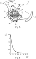
- shows a further schematic view of a gear paddle switch unit according to the invention; and
- Fig. 6
- shows the effect of differing distances of the magnet to its counterpart in a gear paddle switch unit according to the invention.
-
Figure 1 shows a schematic view of a gearpaddle switch unit 10 for triggering a gear shift in a vehicle. Therefore, such a gearpaddle switch unit 10 is preferably arranged in a vehicle, such as in a car. The gearpaddle switch unit 10 may be used by a driver of the vehicle or in other words, a gear shift may be activated by the driver of the vehicle. - The gear
paddle switch unit 10 comprises two steering wheel paddles 12, 14. These steering wheel paddles 12, 14 are arranged in vicinity to aunit 16 which is provided for accommodating a steering wheel. Such aunit 16 is generally widely known in the art and may be provided in vehicles known in the art. Therefore, theunit 16 is not described in detail here. - An
electrical connector arrangement 18 is further shown which may be used for electrical connections for example to a control unit. It may be provided that such anelectrical connector arrangement 18 may be used for transferring instructions with regard to a gear shift like described in detail down below. - Coming back to the steering wheel paddles 12, 14, one of these steering wheel paddles 12, 14 is provided for performing a gear shift to a higher gear and one of these steering wheel paddles 12, 14 is provided for performing a gear shift to a lower shift. With this regard, a gear shift as described here is generally possible in order to perform a gear shift both to a lower gear and to a higher gear.
- The steering wheel paddles 12, 14 each are fixed in a pivoted manner and they thus comprise a pivot axis 20. In other words, the steering wheel paddles 12, 14 may be pivoted, or rotated, respectively, around the pivot axis 20. The pivot axis 20 is located in a bearing 21 for movably fixing the steering wheel paddles 12, 14. The bearing 21 is part of a
main body 52 of the gear paddle switch unit so that the steering wheel paddles 12, 14 may be pivoted relative to themain body 52. - The steering wheel paddles 12, 14 each comprise an
actuating portion 22 for activating thesteering wheel paddle portion 24 for triggering a gear shift. Generally, the actuatingportion 22 and the triggeringportion 24 may be formed as a one part assembly, or they may be formed from two or more parts and may be connected to each other. In the latter embodiment, one of the actuatingportion 22 and the triggeringportion 24 may comprise a reception forming a hub as bearing 21 in which a shaft 26 is provided which forms the pivot axis 20. - It is further provided that each
steering wheel paddle steering wheel paddle steering wheel paddle steering wheel paddle - Like indicated above, the respective
steering wheel paddle steering wheel paddle portion 22, thesteering wheel paddle portion 22, thesteering wheel paddle portion 24 in its resting position. - According to
figure 1 , the steering wheel paddles 12, 14 are shown in a resting position. -
Figure 1 further shows that in the triggeringportion 24 of each of the steering wheel paddles 12, 14 at least onemagnet element 28 is provided. Themagnet element 28 serves for an improved security and an improved functionality like described down below and is part of a triggeringunit 25, wherein the triggeringunit 25 is configured for providing a magnetic force for preloading the triggeringportion 24 in the resting position for providing a haptic feedback to a user actuating thesteering wheel paddle - Further, a
support 30 is shown. Thesupport 30 is part of themain body 52 and is formed from a ferromagnetic material, such as from iron. In more detail, thesupport 30 is formed as a bracket which traverses themagnets 28 of both steering wheel paddles 12, 14. Thesupport 30 may be fixed for example by means of screws, which may proceed throughrespective holes 48 and may interact withthreads 50, which may be part of themain body 52. Themain body 52 may also form a stopper for the triggeringportion 24 when the steering wheel paddles 12, 14 are transferred into the triggering position. - The
support 30 may be provided in order to support the steering wheel paddles 12, 14 in case they are arranged in their resting position. In order to get in contact with thesupport 30, the steering wheel paddles 12, 14 each may comprise aspacer 32 for coming in contact to thesupport 30, or the bracket, respectively. Thespacer 32 may for example be formed from a polymeric material in order not to be influenced from the magnetic force of the at least onemagnet element 28. - In
figure 1 , thesupport 30, or the bracket, respectively, is shown as separate part not being fixed above the at least onemagnet element 28 for illustration purposes.Figure 5 shows thesupport 30 being fixed above the at least onemagnet 28 and may in this arrangement serve as stopping point for the triggeringportion 24 of the respective steering wheel paddles 12, 14 like described below. Further, it can be seen that the bracket, or thesupport 30, respectively, is part of themain body 52. - Coming back to
figure 1 , themagnet elements 28 which are provided in the triggeringportions 24, or themain body 40 of the triggeringportions 24, respectively, of the steering wheel paddles 12, 14 are formed as a neodymium magnet. This embodiment may allow themagnet elements 28 to have a very strong magnetization which in turn allows a very strong magnetic force and thus a very strong attraction of the counterpart which interacts with themagnet elements 28. According tofigure 1 , thus, a very strong attraction to the bracket and thus themain body 52 is achieved. Further, and in more detail, themagnet elements 28 as shown infigure 1 are designed as disc magnets being arranged with a radial magnetization. With this regard, the disc magnets comprise anouter portion 34 which may be formed as north pole and aninner portion 36 which may be formed as south pole. This is shown in more detail infigures 2 and3 . - The triggering
portions 24 comprising themagnet elements 28 are shown in more detail infigure 2 . It can be seen in more detail that each triggeringportion 24 comprises aspacer 32 like indicated above. Thespacers 32 each may be formed in a plate-like manner and may be fixed to themain body 40 of the triggeringportion 24 for example by means of an adhesive or the like. Next to thespacer 32, themagnet elements 28 are shown with theirinner portion 36 and itsouter portion 34. - It is further provided that in a resting position of the steering wheel paddles 12, 14, the triggering
portion 24 is positioned in contact to thesupport 30. In detail, thespacer 32 of the steering wheel paddles 12, 14 may be in contact with thesupport 30. On the other side, in case the steering wheel paddles 12, 14 are in a triggering position, the respective triggeringportion 24 is positioned spaced apart from thesupport 30. Like indicated above, the steering wheel paddles 12, 14 are arranged such, that the steering wheel paddles 12, 14 may be pivoted by activating the activatingportion 22 for positioning thesteering wheel paddle - In order to trigger a gear shift, a sensor not shown as such may be provided for detecting the position of the triggering
portion 24. For example, a magnet sensor may be provided. This may allow detecting if the steering wheel paddles 12, 14 are in a resting position or in a triggering position. Based on the detection of the sensor, a gear shift may be triggered electronically by activating a respective mechanism, for example. Performing a gear shift based on electronic signals, however, is generally known in the art and is not described in detail here. The sensor may be provided in themain body 52, for example. - Due to the provision of the
magnet element 28, the triggeringportion 24 may be placed in contact to thesupport 30 by means of a magnetic preload force such, that increasing the distance of the triggeringportion 24 to thesupport 30 is performed against the magnetic force. In other words, the magnetic preload force serves for a magnetic attraction of the particularlyferromagnetic support 30 to the at least onemagnet 28. In other words, the triggeringportion 24 is held in the resting position preloaded with a preload force caused by a triggeringunit 25 so that the triggeringportion 24 is moved from the triggering position to the resting position by said preload force after release of thesteering wheel paddle figure 1 , thesupport 30 is the ferromagnetic counterpart. According to this embodiment, the triggeringunit 25 comprises themagnet element 28 as well as the bracket, or the main body, respectively, as ferromagnetic counterpart. - Providing the gear
paddle switch unit 10 as described above may give the advantage that due to the fact that activating the steering wheel paddles 12, 14 has to be performed against the magnetic force, a strong haptic feedback to the driver of the vehicle and thus for the person who activated the steering wheel paddles 12, 14 may be provided. In fact, the feeling of the actuation is now provided by the magnetic attraction of themagnet element 28 towards thesupport 30 or the countart, respectively. Therefore, providing a solution according to the present invention may significantly improve using a gearpaddle switch unit 10 for triggering a gear shift and thus especially such a gearpaddle switch unit 10 which uses steering wheel paddles 12, 14. - Further, the figures clearly show that the solution according to the present invention avoids mechanical parts which touch each other so that mechanical wear and the problems arising therewith, such as aging which may lead to damages, can be excluded. Accordingly, the solution according to the invention may be much more reliable compared to the solutions of the prior art.
- Apart from the above, the obtained activation may provide results which are much quicker due to the magnet behavior compared to solutions according to the prior art. Thus, gear shifts as such may be performed with a higher speed which may be an important factor especially for sportive cars, however not being restricted to sportive cars. In detail, an accelerated gear shift may be advantageous for any vehicle.
- With regard to the magnetic attraction of the
support 30 to themagnet 28, it may be advantageous that the distance between themagnet 28 and thesupport 30, or generally the counterpart, may be arranged in a very specific manner. With this regard, it is referred tofigure 6 . - In
figure 6 , the magnetic force leading to a magnetic attraction in kg is shown on the y-axis, whereas the x-axis shows the distance in mm between themagnet element 28 and a respective counterpart being attracted by themagnet element 28, such as thesupport 30, for a typical neodymium magnet. It can be seen that when providing a very small distance, the magnetic force changes significantly when changing the distance. However, the magnetic force is comparably strong. On the other side, in case the distance is comparably large, the change of the magnetic force is comparably small when changing the distance between the magnet and its counterpart. On the other side, the magnetic force is comparably small. - Therefore, the distance should be adjusted in a very defined manner in order to have long-time reliable and defined working properties such as a defined strength of gear shift feedback. It could be shown that a very effective compromise allowing the advantages of the invention and further defined working properties such as a defined haptic feedback in case the
magnet 28 is positioned in a resting position of thesteering wheel paddle support 30 in a range of > 0 mm to ≤ 5mm. - This may on the one hand be realized by arranging the
spacers 32 respectively. - Apart from that it is provided that the distance of the
magnet 28 to thesupport 30 is adjustable. In order to achieve this, it is provided that themagnet 28 is fixed by means of ascrew 38 against a spring force. With this regard, themain body 40 of the triggeringportion 24, comprises a reception, wherein beneath themagnet element 28 there is provided an element which exerts a spring force against themagnet element 28. For example, the element providing a spring force may be a simple spring or it may be an elastic element which is compressed when mounting and fixing the magnet. Such an elastic element may be formed from ethylene propylene diene rubber (EPDM), for example. The position of themagnet element 28 with regard to thesupport 30 may thus be defined by the spring. In this case, by rotating the screw, the distance of themagnet 30 to the support may be adjusted in an easy manner. - In order to achieve this even in case the
system 10 is fully instructed in a vehicle, thesupport 30 or the bracket respectively comprisesholes 46 through which thescrew 38 can be used. -
Figure 3 shows a further embodiment of a gearpaddle switch unit 10 for triggering a gear shift in a vehicle. According to this embodiment, twomagnet elements 28 are provided in each triggeringportion 24. Thesemagnet elements 28 are formed as rod magnets and are arranged such, that they show poles having a reversed orientation. According tofigure 3 , thenorth pole portions 42 as well as thesouth pole portions 44 are shown. Especially this arrangement may allow a very defined and further a very strong magnetic field which in turn allows a very strong magnetic attraction of the respective counterpart, i.e. thesupport 30. Therefore, this embodiment allows that the advantages as described before may be achieved especially effectively. - With this regard, the magnetic fields of
respective magnet elements 28 are shown infigure 4 . In detail, the magnetic field of to reverse orientated rod magnets are shown infigure 4a and a disc magnet is shown inFig 4b . - With regard to
figure 4a , it can be seen that the rod magnets each have theirnorth pole portions 42 and theirsouth pole portions 44. When being arranged in a reverse orientation, the magnetic field is concentrated in an area located in vicinity to themagnet elements 28, like shown by the arrows. Therefore, a very strong field may be achieved which may allow a very strong magnetic attraction to the support. - The same may apply when providing a disc magnet having a radial magnetization. This is shown in
figure 4b , where anorth pole portion 42 is provided at the circumference and thus at theouter portion 34, whereas asouth pole portion 44 is provided in the center of themagnet 28 and thus in theinner portion 36. The magnetic field again is visualized by the arrows which indicates a strong attraction to the counterpart of themagnet element 28, such as to thesupport 30. - Therefore, the figures show embodiments in which the
magnet element 28, or the plurality ofmagnet elements 28, respectively, is provided in the triggeringportion 24 of the steering wheel paddles 12, 14. However, the description is in a corresponding manner also valid for an embodiment in which themagnet element 28 or the plurality ofmagnet elements 28, respectively, is provided in thesupport 30, as it is clearly understandable for the person skilled in the art. - As a result, when providing a gear
paddle switch unit 10 like described above, a gear shift may be provided faster, more reliable and with an improved haptic feedback, which strongly improves a gear shift especially with regard to gearpaddle switch units 10 comprising steering wheel paddles for triggering a gear shift. -
- 10
- gear paddle switch unit
- 12
- steering wheel paddle
- 14
- steering wheel paddle
- 16
- unit
- 18
- connector arrangement
- 20
- pivot axis
- 21
- bearing
- 22
- actuating portion
- 24
- triggering portion
- 25
- triggering unit
- 26
- shaft
- 28
- magnet element
- 30
- support
- 32
- spacer
- 34
- outer portion
- 36
- inner portion
- 38
- screw
- 40
- main body
- 42
- north pole portion
- 44
- south pole portion
- 46
- hole
- 48
- hole
- 50
- thread
- 52
- main body
Claims (12)
- Gear paddle switch unit for triggering a gear shift in a vehicle, wherein the gear paddle switch unit (10) comprises a main body (52), and at least one steering wheel paddle (12, 14) with an actuation portion (22) for actuating the steering wheel paddle (12, 14) by a user and an opposing triggering portion (24) for triggering a gear shift, wherein the gear paddle switch unit (10) further comprises a bearing (21) for movably fixing the at least one steering wheel paddle (12, 14) such, that the triggering portion (24) is pivotable relatively to the main body (52) between a resting position and a triggering position, wherein the triggering portion (24) is held in the resting position preloaded with a preload force caused by a triggering unit (25) so that the triggering portion (24) is moved from the triggering position to the resting position by said preload force after release of the steering wheel paddle (12, 14) by the user in the triggering position,
characterised in that,
the triggering unit (25) is configured for providing a magnetic force for preloading the triggering portion (24) in the resting position for providing a haptic feedback to a user when actuating the steering wheel paddle (12, 14), whereby the triggering unit (25) comprises a magnet element (28) and a ferromagnetic counterpart, whereby the magnet element (28) is provided at the triggering portion (24) and in that the ferromagnetic counterpart is comprised by the main body (52), and whereby the main body (52) comprises a bracket as ferromagnetic counterpart which traverses the magnet element (28) of the steering wheel paddle (12, 14). - Gear paddle switch unit according to claim 1, characterized in that the magnet element (28) is provided at the main body (52) and in that the ferromagnetic counterpart is comprised by the triggering portion (24).
- Gear paddle switch unit according to claim 1, characterized in the magnet element (28) is provided at the triggering portion (24) and in that the ferromagnetic counterpart is comprised by a part distinct from the main body (52) or in that that the ferromagnetic counterpart is comprised by the triggering portion (24) and the magnet element (28) is provided at a part distinct from the main body (52).
- Gear paddle switch unit according to any of claims 1 to 3, characterized in that the bearing (21) is part of the main body (52).
- Gear paddle switch unit according to any of claims 1 to 4, characterized in that a sensor is provided for detecting the position of the triggering portion (24).
- Gear paddle switch unit according to any of claims 1 to 5, characterized in that the magnet element (28) is formed as a neodymium magnet.
- Gear paddle switch unit according to any of claims 1 to 6, characterized in that at least one disc magnet is provided, wherein the disc magnet is formed with a radial magnetization.
- Gear paddle switch unit according to any of claims 1 to 7, characterized in that at least one rod magnet is provided.
- Gear paddle switch unit according to any of claims 1 to 8, characterized in the distance of the magnet element (28) to the ferromagnetic counterpart is adjustable.
- Gear paddle switch unit according to any of claims 1 to 9, characterized in that the triggering portion (24) comprises a spacer (32) for coming in contact to a support (30) for supporting the triggering portion (24) in a resting position or that a support (30) for supporting the triggering portion (24) in a resting position comprises a spacer (32) for coming in contact to the triggering portion (24).
- Gear paddle switch unit according to any of claims 1 to 10, characterized in that the magnet element (28) is positioned in a resting position of the steering wheel paddle (12, 14) in a distance to the ferromagnetic counterpart in a range of > 0 mm to ≤ 5mm.
- Gear paddle switch unit according to any of claims 1 to 11, characterized in that the gear paddle switch unit (10) comprises two steering wheel paddles (12, 14).
Applications Claiming Priority (1)
| Application Number | Priority Date | Filing Date | Title |
|---|---|---|---|
| DE102018127979.5A DE102018127979A1 (en) | 2018-11-08 | 2018-11-08 | Gear shift rocker switch unit for triggering a gear shift process in a vehicle |
Publications (2)
| Publication Number | Publication Date |
|---|---|
| EP3650735A1 EP3650735A1 (en) | 2020-05-13 |
| EP3650735B1 true EP3650735B1 (en) | 2022-02-16 |
Family
ID=68281113
Family Applications (1)
| Application Number | Title | Priority Date | Filing Date |
|---|---|---|---|
| EP19203450.2A Active EP3650735B1 (en) | 2018-11-08 | 2019-10-16 | Gear paddle switch unit for triggering a gear shift in a vehicle |
Country Status (2)
| Country | Link |
|---|---|
| EP (1) | EP3650735B1 (en) |
| DE (1) | DE102018127979A1 (en) |
Families Citing this family (2)
| Publication number | Priority date | Publication date | Assignee | Title |
|---|---|---|---|---|
| CN112837578A (en) * | 2021-04-06 | 2021-05-25 | 深圳市卡妙思电子科技有限公司 | A device for simulating the force feedback of the shift paddles of the automobile steering wheel |
| CN113352883B (en) * | 2021-06-28 | 2023-07-25 | 宁波昌扬机械工业有限公司 | Steering wheel shifting plectrum |
Family Cites Families (6)
| Publication number | Priority date | Publication date | Assignee | Title |
|---|---|---|---|---|
| US5224393A (en) * | 1990-05-11 | 1993-07-06 | Honda Giken Kogyo Kabushiki Kaisha | Electronically controlled transmission and steering wheel located shift mechanism |
| FR2872957B1 (en) * | 2004-07-08 | 2006-09-22 | Sc2N Sa | MAGNETIC INDEX CONTROL DEVICE |
| DE102006002634B4 (en) * | 2005-07-19 | 2009-11-26 | Preh Gmbh | Control element with tilt-feel |
| JP2009035099A (en) * | 2007-08-01 | 2009-02-19 | Tokai Rika Co Ltd | Vehicular shift lever switch |
| DE102009042497A1 (en) * | 2009-09-15 | 2011-03-31 | Dr. Ing. H.C. F. Porsche Aktiengesellschaft | Steering wheel with at least one shift paddle |
| US8996261B2 (en) * | 2012-10-25 | 2015-03-31 | Toyota Motor Engineering & Manufacturing North America, Inc. | Automobile paddle shifters locking device and system |
-
2018
- 2018-11-08 DE DE102018127979.5A patent/DE102018127979A1/en not_active Withdrawn
-
2019
- 2019-10-16 EP EP19203450.2A patent/EP3650735B1/en active Active
Also Published As
| Publication number | Publication date |
|---|---|
| EP3650735A1 (en) | 2020-05-13 |
| DE102018127979A1 (en) | 2020-05-14 |
Similar Documents
| Publication | Publication Date | Title |
|---|---|---|
| US8284003B2 (en) | Operating element having improved tilting haptics | |
| EP3650735B1 (en) | Gear paddle switch unit for triggering a gear shift in a vehicle | |
| US9457660B2 (en) | Accelerator pedal apparatus | |
| US10088040B2 (en) | Shifter with electromagnetic park lock system | |
| CN101669182B (en) | Magnetic switch device | |
| US7619376B2 (en) | Detent mechanism | |
| US20080184843A1 (en) | Accelerator Pedal Module With Magnetic Sensor | |
| JP7292011B2 (en) | Rotation detection joystick | |
| US10066682B2 (en) | Shaft support structure for selectable one-way clutch | |
| US8899636B2 (en) | Magnetic latch | |
| US10277225B2 (en) | Switching device having a haptic feedback | |
| CN112969628B (en) | Aligning torque generating device for motor vehicles | |
| JP2013533589A5 (en) | ||
| US6689016B2 (en) | Method and apparatus for producing downshift signals | |
| JP2005500697A5 (en) | ||
| EP2944936B1 (en) | Magnetic load sensor and electric brake device | |
| EP2301787B1 (en) | Accelerator pedal apparatus | |
| WO2008010186A3 (en) | A twist-grip control device, in particular for motor vehicles | |
| EP3557367B1 (en) | Operation device and vehicle shift device using said operation device | |
| EP3550397A1 (en) | Operation device and vehicular shifting apparatus using operation device | |
| US5774042A (en) | Device for providing tactile indication of pedal position | |
| US20090278638A1 (en) | Control Device Comprising Means for Indexing the Position of the Control Means | |
| CN115443515B (en) | Operating device for mounting on a vehicle | |
| US20140167890A1 (en) | Electrical switch arrangement and device for controlling an apparatus comprising such an arrangement | |
| JP2615178B2 (en) | Locking device for switchgear with electromagnetic actuator |
Legal Events
| Date | Code | Title | Description |
|---|---|---|---|
| PUAI | Public reference made under article 153(3) epc to a published international application that has entered the european phase |
Free format text: ORIGINAL CODE: 0009012 |
|
| STAA | Information on the status of an ep patent application or granted ep patent |
Free format text: STATUS: THE APPLICATION HAS BEEN PUBLISHED |
|
| AK | Designated contracting states |
Kind code of ref document: A1 Designated state(s): AL AT BE BG CH CY CZ DE DK EE ES FI FR GB GR HR HU IE IS IT LI LT LU LV MC MK MT NL NO PL PT RO RS SE SI SK SM TR |
|
| AX | Request for extension of the european patent |
Extension state: BA ME |
|
| STAA | Information on the status of an ep patent application or granted ep patent |
Free format text: STATUS: REQUEST FOR EXAMINATION WAS MADE |
|
| 17P | Request for examination filed |
Effective date: 20201111 |
|
| RBV | Designated contracting states (corrected) |
Designated state(s): AL AT BE BG CH CY CZ DE DK EE ES FI FR GB GR HR HU IE IS IT LI LT LU LV MC MK MT NL NO PL PT RO RS SE SI SK SM TR |
|
| GRAP | Despatch of communication of intention to grant a patent |
Free format text: ORIGINAL CODE: EPIDOSNIGR1 |
|
| STAA | Information on the status of an ep patent application or granted ep patent |
Free format text: STATUS: GRANT OF PATENT IS INTENDED |
|
| INTG | Intention to grant announced |
Effective date: 20210929 |
|
| RIN1 | Information on inventor provided before grant (corrected) |
Inventor name: PESTARINO, FABIO Inventor name: MAGI, GIANCARLO Inventor name: MASUELLI, DOMENICO |
|
| GRAS | Grant fee paid |
Free format text: ORIGINAL CODE: EPIDOSNIGR3 |
|
| GRAA | (expected) grant |
Free format text: ORIGINAL CODE: 0009210 |
|
| STAA | Information on the status of an ep patent application or granted ep patent |
Free format text: STATUS: THE PATENT HAS BEEN GRANTED |
|
| AK | Designated contracting states |
Kind code of ref document: B1 Designated state(s): AL AT BE BG CH CY CZ DE DK EE ES FI FR GB GR HR HU IE IS IT LI LT LU LV MC MK MT NL NO PL PT RO RS SE SI SK SM TR |
|
| REG | Reference to a national code |
Ref country code: GB Ref legal event code: FG4D |
|
| REG | Reference to a national code |
Ref country code: CH Ref legal event code: EP |
|
| REG | Reference to a national code |
Ref country code: DE Ref legal event code: R096 Ref document number: 602019011629 Country of ref document: DE |
|
| REG | Reference to a national code |
Ref country code: AT Ref legal event code: REF Ref document number: 1469069 Country of ref document: AT Kind code of ref document: T Effective date: 20220315 |
|
| REG | Reference to a national code |
Ref country code: IE Ref legal event code: FG4D |
|
| REG | Reference to a national code |
Ref country code: LT Ref legal event code: MG9D |
|
| REG | Reference to a national code |
Ref country code: NL Ref legal event code: MP Effective date: 20220216 |
|
| REG | Reference to a national code |
Ref country code: AT Ref legal event code: MK05 Ref document number: 1469069 Country of ref document: AT Kind code of ref document: T Effective date: 20220216 |
|
| PG25 | Lapsed in a contracting state [announced via postgrant information from national office to epo] |
Ref country code: SE Free format text: LAPSE BECAUSE OF FAILURE TO SUBMIT A TRANSLATION OF THE DESCRIPTION OR TO PAY THE FEE WITHIN THE PRESCRIBED TIME-LIMIT Effective date: 20220216 Ref country code: RS Free format text: LAPSE BECAUSE OF FAILURE TO SUBMIT A TRANSLATION OF THE DESCRIPTION OR TO PAY THE FEE WITHIN THE PRESCRIBED TIME-LIMIT Effective date: 20220216 Ref country code: PT Free format text: LAPSE BECAUSE OF FAILURE TO SUBMIT A TRANSLATION OF THE DESCRIPTION OR TO PAY THE FEE WITHIN THE PRESCRIBED TIME-LIMIT Effective date: 20220616 Ref country code: NO Free format text: LAPSE BECAUSE OF FAILURE TO SUBMIT A TRANSLATION OF THE DESCRIPTION OR TO PAY THE FEE WITHIN THE PRESCRIBED TIME-LIMIT Effective date: 20220516 Ref country code: NL Free format text: LAPSE BECAUSE OF FAILURE TO SUBMIT A TRANSLATION OF THE DESCRIPTION OR TO PAY THE FEE WITHIN THE PRESCRIBED TIME-LIMIT Effective date: 20220216 Ref country code: LT Free format text: LAPSE BECAUSE OF FAILURE TO SUBMIT A TRANSLATION OF THE DESCRIPTION OR TO PAY THE FEE WITHIN THE PRESCRIBED TIME-LIMIT Effective date: 20220216 Ref country code: HR Free format text: LAPSE BECAUSE OF FAILURE TO SUBMIT A TRANSLATION OF THE DESCRIPTION OR TO PAY THE FEE WITHIN THE PRESCRIBED TIME-LIMIT Effective date: 20220216 Ref country code: ES Free format text: LAPSE BECAUSE OF FAILURE TO SUBMIT A TRANSLATION OF THE DESCRIPTION OR TO PAY THE FEE WITHIN THE PRESCRIBED TIME-LIMIT Effective date: 20220216 Ref country code: BG Free format text: LAPSE BECAUSE OF FAILURE TO SUBMIT A TRANSLATION OF THE DESCRIPTION OR TO PAY THE FEE WITHIN THE PRESCRIBED TIME-LIMIT Effective date: 20220516 |
|
| PG25 | Lapsed in a contracting state [announced via postgrant information from national office to epo] |
Ref country code: PL Free format text: LAPSE BECAUSE OF FAILURE TO SUBMIT A TRANSLATION OF THE DESCRIPTION OR TO PAY THE FEE WITHIN THE PRESCRIBED TIME-LIMIT Effective date: 20220216 Ref country code: LV Free format text: LAPSE BECAUSE OF FAILURE TO SUBMIT A TRANSLATION OF THE DESCRIPTION OR TO PAY THE FEE WITHIN THE PRESCRIBED TIME-LIMIT Effective date: 20220216 Ref country code: GR Free format text: LAPSE BECAUSE OF FAILURE TO SUBMIT A TRANSLATION OF THE DESCRIPTION OR TO PAY THE FEE WITHIN THE PRESCRIBED TIME-LIMIT Effective date: 20220517 Ref country code: FI Free format text: LAPSE BECAUSE OF FAILURE TO SUBMIT A TRANSLATION OF THE DESCRIPTION OR TO PAY THE FEE WITHIN THE PRESCRIBED TIME-LIMIT Effective date: 20220216 Ref country code: AT Free format text: LAPSE BECAUSE OF FAILURE TO SUBMIT A TRANSLATION OF THE DESCRIPTION OR TO PAY THE FEE WITHIN THE PRESCRIBED TIME-LIMIT Effective date: 20220216 |
|
| PG25 | Lapsed in a contracting state [announced via postgrant information from national office to epo] |
Ref country code: IS Free format text: LAPSE BECAUSE OF FAILURE TO SUBMIT A TRANSLATION OF THE DESCRIPTION OR TO PAY THE FEE WITHIN THE PRESCRIBED TIME-LIMIT Effective date: 20220617 |
|
| PG25 | Lapsed in a contracting state [announced via postgrant information from national office to epo] |
Ref country code: SM Free format text: LAPSE BECAUSE OF FAILURE TO SUBMIT A TRANSLATION OF THE DESCRIPTION OR TO PAY THE FEE WITHIN THE PRESCRIBED TIME-LIMIT Effective date: 20220216 Ref country code: SK Free format text: LAPSE BECAUSE OF FAILURE TO SUBMIT A TRANSLATION OF THE DESCRIPTION OR TO PAY THE FEE WITHIN THE PRESCRIBED TIME-LIMIT Effective date: 20220216 Ref country code: RO Free format text: LAPSE BECAUSE OF FAILURE TO SUBMIT A TRANSLATION OF THE DESCRIPTION OR TO PAY THE FEE WITHIN THE PRESCRIBED TIME-LIMIT Effective date: 20220216 Ref country code: EE Free format text: LAPSE BECAUSE OF FAILURE TO SUBMIT A TRANSLATION OF THE DESCRIPTION OR TO PAY THE FEE WITHIN THE PRESCRIBED TIME-LIMIT Effective date: 20220216 Ref country code: DK Free format text: LAPSE BECAUSE OF FAILURE TO SUBMIT A TRANSLATION OF THE DESCRIPTION OR TO PAY THE FEE WITHIN THE PRESCRIBED TIME-LIMIT Effective date: 20220216 Ref country code: CZ Free format text: LAPSE BECAUSE OF FAILURE TO SUBMIT A TRANSLATION OF THE DESCRIPTION OR TO PAY THE FEE WITHIN THE PRESCRIBED TIME-LIMIT Effective date: 20220216 |
|
| REG | Reference to a national code |
Ref country code: DE Ref legal event code: R097 Ref document number: 602019011629 Country of ref document: DE |
|
| PG25 | Lapsed in a contracting state [announced via postgrant information from national office to epo] |
Ref country code: AL Free format text: LAPSE BECAUSE OF FAILURE TO SUBMIT A TRANSLATION OF THE DESCRIPTION OR TO PAY THE FEE WITHIN THE PRESCRIBED TIME-LIMIT Effective date: 20220216 |
|
| PLBE | No opposition filed within time limit |
Free format text: ORIGINAL CODE: 0009261 |
|
| STAA | Information on the status of an ep patent application or granted ep patent |
Free format text: STATUS: NO OPPOSITION FILED WITHIN TIME LIMIT |
|
| 26N | No opposition filed |
Effective date: 20221117 |
|
| PG25 | Lapsed in a contracting state [announced via postgrant information from national office to epo] |
Ref country code: SI Free format text: LAPSE BECAUSE OF FAILURE TO SUBMIT A TRANSLATION OF THE DESCRIPTION OR TO PAY THE FEE WITHIN THE PRESCRIBED TIME-LIMIT Effective date: 20220216 |
|
| PG25 | Lapsed in a contracting state [announced via postgrant information from national office to epo] |
Ref country code: MC Free format text: LAPSE BECAUSE OF FAILURE TO SUBMIT A TRANSLATION OF THE DESCRIPTION OR TO PAY THE FEE WITHIN THE PRESCRIBED TIME-LIMIT Effective date: 20220216 |
|
| REG | Reference to a national code |
Ref country code: CH Ref legal event code: PL |
|
| REG | Reference to a national code |
Ref country code: BE Ref legal event code: MM Effective date: 20221031 |
|
| PG25 | Lapsed in a contracting state [announced via postgrant information from national office to epo] |
Ref country code: LU Free format text: LAPSE BECAUSE OF NON-PAYMENT OF DUE FEES Effective date: 20221016 |
|
| P01 | Opt-out of the competence of the unified patent court (upc) registered |
Effective date: 20230528 |
|
| PG25 | Lapsed in a contracting state [announced via postgrant information from national office to epo] |
Ref country code: LI Free format text: LAPSE BECAUSE OF NON-PAYMENT OF DUE FEES Effective date: 20221031 Ref country code: IT Free format text: LAPSE BECAUSE OF FAILURE TO SUBMIT A TRANSLATION OF THE DESCRIPTION OR TO PAY THE FEE WITHIN THE PRESCRIBED TIME-LIMIT Effective date: 20220216 Ref country code: CH Free format text: LAPSE BECAUSE OF NON-PAYMENT OF DUE FEES Effective date: 20221031 |
|
| PG25 | Lapsed in a contracting state [announced via postgrant information from national office to epo] |
Ref country code: BE Free format text: LAPSE BECAUSE OF NON-PAYMENT OF DUE FEES Effective date: 20221031 |
|
| PG25 | Lapsed in a contracting state [announced via postgrant information from national office to epo] |
Ref country code: IE Free format text: LAPSE BECAUSE OF NON-PAYMENT OF DUE FEES Effective date: 20221016 |
|
| PG25 | Lapsed in a contracting state [announced via postgrant information from national office to epo] |
Ref country code: HU Free format text: LAPSE BECAUSE OF FAILURE TO SUBMIT A TRANSLATION OF THE DESCRIPTION OR TO PAY THE FEE WITHIN THE PRESCRIBED TIME-LIMIT; INVALID AB INITIO Effective date: 20191016 |
|
| PG25 | Lapsed in a contracting state [announced via postgrant information from national office to epo] |
Ref country code: CY Free format text: LAPSE BECAUSE OF FAILURE TO SUBMIT A TRANSLATION OF THE DESCRIPTION OR TO PAY THE FEE WITHIN THE PRESCRIBED TIME-LIMIT Effective date: 20220216 |
|
| PG25 | Lapsed in a contracting state [announced via postgrant information from national office to epo] |
Ref country code: MK Free format text: LAPSE BECAUSE OF FAILURE TO SUBMIT A TRANSLATION OF THE DESCRIPTION OR TO PAY THE FEE WITHIN THE PRESCRIBED TIME-LIMIT Effective date: 20220216 |
|
| PG25 | Lapsed in a contracting state [announced via postgrant information from national office to epo] |
Ref country code: TR Free format text: LAPSE BECAUSE OF FAILURE TO SUBMIT A TRANSLATION OF THE DESCRIPTION OR TO PAY THE FEE WITHIN THE PRESCRIBED TIME-LIMIT Effective date: 20220216 |
|
| PG25 | Lapsed in a contracting state [announced via postgrant information from national office to epo] |
Ref country code: MT Free format text: LAPSE BECAUSE OF FAILURE TO SUBMIT A TRANSLATION OF THE DESCRIPTION OR TO PAY THE FEE WITHIN THE PRESCRIBED TIME-LIMIT Effective date: 20220216 |
|
| PGFP | Annual fee paid to national office [announced via postgrant information from national office to epo] |
Ref country code: DE Payment date: 20251015 Year of fee payment: 7 |
|
| PGFP | Annual fee paid to national office [announced via postgrant information from national office to epo] |
Ref country code: GB Payment date: 20251023 Year of fee payment: 7 |
|
| PGFP | Annual fee paid to national office [announced via postgrant information from national office to epo] |
Ref country code: FR Payment date: 20251027 Year of fee payment: 7 |