EP3650660A1 - Gas turbine engine structure with integrated actuation features - Google Patents
Gas turbine engine structure with integrated actuation features Download PDFInfo
- Publication number
- EP3650660A1 EP3650660A1 EP19207525.7A EP19207525A EP3650660A1 EP 3650660 A1 EP3650660 A1 EP 3650660A1 EP 19207525 A EP19207525 A EP 19207525A EP 3650660 A1 EP3650660 A1 EP 3650660A1
- Authority
- EP
- European Patent Office
- Prior art keywords
- hydraulic
- hydraulic fluid
- hydraulic cylinder
- case wall
- fluid passages
- Prior art date
- Legal status (The legal status is an assumption and is not a legal conclusion. Google has not performed a legal analysis and makes no representation as to the accuracy of the status listed.)
- Granted
Links
Images


Classifications
-
- F—MECHANICAL ENGINEERING; LIGHTING; HEATING; WEAPONS; BLASTING
- F01—MACHINES OR ENGINES IN GENERAL; ENGINE PLANTS IN GENERAL; STEAM ENGINES
- F01D—NON-POSITIVE DISPLACEMENT MACHINES OR ENGINES, e.g. STEAM TURBINES
- F01D17/00—Regulating or controlling by varying flow
- F01D17/10—Final actuators
- F01D17/12—Final actuators arranged in stator parts
- F01D17/14—Final actuators arranged in stator parts varying effective cross-sectional area of nozzles or guide conduits
- F01D17/16—Final actuators arranged in stator parts varying effective cross-sectional area of nozzles or guide conduits by means of nozzle vanes
- F01D17/162—Final actuators arranged in stator parts varying effective cross-sectional area of nozzles or guide conduits by means of nozzle vanes for axial flow, i.e. the vanes turning around axes which are essentially perpendicular to the rotor centre line
-
- B—PERFORMING OPERATIONS; TRANSPORTING
- B22—CASTING; POWDER METALLURGY
- B22F—WORKING METALLIC POWDER; MANUFACTURE OF ARTICLES FROM METALLIC POWDER; MAKING METALLIC POWDER; APPARATUS OR DEVICES SPECIALLY ADAPTED FOR METALLIC POWDER
- B22F5/00—Manufacture of workpieces or articles from metallic powder characterised by the special shape of the product
- B22F5/009—Manufacture of workpieces or articles from metallic powder characterised by the special shape of the product of turbine components other than turbine blades
-
- B—PERFORMING OPERATIONS; TRANSPORTING
- B33—ADDITIVE MANUFACTURING TECHNOLOGY
- B33Y—ADDITIVE MANUFACTURING, i.e. MANUFACTURING OF THREE-DIMENSIONAL [3D] OBJECTS BY ADDITIVE DEPOSITION, ADDITIVE AGGLOMERATION OR ADDITIVE LAYERING, e.g. BY 3D PRINTING, STEREOLITHOGRAPHY OR SELECTIVE LASER SINTERING
- B33Y80/00—Products made by additive manufacturing
-
- F—MECHANICAL ENGINEERING; LIGHTING; HEATING; WEAPONS; BLASTING
- F01—MACHINES OR ENGINES IN GENERAL; ENGINE PLANTS IN GENERAL; STEAM ENGINES
- F01D—NON-POSITIVE DISPLACEMENT MACHINES OR ENGINES, e.g. STEAM TURBINES
- F01D17/00—Regulating or controlling by varying flow
- F01D17/20—Devices dealing with sensing elements or final actuators or transmitting means between them, e.g. power-assisted
- F01D17/22—Devices dealing with sensing elements or final actuators or transmitting means between them, e.g. power-assisted the operation or power assistance being predominantly non-mechanical
- F01D17/26—Devices dealing with sensing elements or final actuators or transmitting means between them, e.g. power-assisted the operation or power assistance being predominantly non-mechanical fluid, e.g. hydraulic
-
- F—MECHANICAL ENGINEERING; LIGHTING; HEATING; WEAPONS; BLASTING
- F01—MACHINES OR ENGINES IN GENERAL; ENGINE PLANTS IN GENERAL; STEAM ENGINES
- F01D—NON-POSITIVE DISPLACEMENT MACHINES OR ENGINES, e.g. STEAM TURBINES
- F01D25/00—Component parts, details, or accessories, not provided for in, or of interest apart from, other groups
- F01D25/24—Casings; Casing parts, e.g. diaphragms, casing fastenings
-
- F—MECHANICAL ENGINEERING; LIGHTING; HEATING; WEAPONS; BLASTING
- F04—POSITIVE - DISPLACEMENT MACHINES FOR LIQUIDS; PUMPS FOR LIQUIDS OR ELASTIC FLUIDS
- F04D—NON-POSITIVE-DISPLACEMENT PUMPS
- F04D29/00—Details, component parts, or accessories
- F04D29/40—Casings; Connections of working fluid
-
- F—MECHANICAL ENGINEERING; LIGHTING; HEATING; WEAPONS; BLASTING
- F04—POSITIVE - DISPLACEMENT MACHINES FOR LIQUIDS; PUMPS FOR LIQUIDS OR ELASTIC FLUIDS
- F04D—NON-POSITIVE-DISPLACEMENT PUMPS
- F04D29/00—Details, component parts, or accessories
- F04D29/40—Casings; Connections of working fluid
- F04D29/52—Casings; Connections of working fluid for axial pumps
- F04D29/54—Fluid-guiding means, e.g. diffusers
- F04D29/56—Fluid-guiding means, e.g. diffusers adjustable
- F04D29/563—Fluid-guiding means, e.g. diffusers adjustable specially adapted for elastic fluid pumps
-
- F—MECHANICAL ENGINEERING; LIGHTING; HEATING; WEAPONS; BLASTING
- F05—INDEXING SCHEMES RELATING TO ENGINES OR PUMPS IN VARIOUS SUBCLASSES OF CLASSES F01-F04
- F05D—INDEXING SCHEME FOR ASPECTS RELATING TO NON-POSITIVE-DISPLACEMENT MACHINES OR ENGINES, GAS-TURBINES OR JET-PROPULSION PLANTS
- F05D2220/00—Application
- F05D2220/30—Application in turbines
- F05D2220/32—Application in turbines in gas turbines
-
- F—MECHANICAL ENGINEERING; LIGHTING; HEATING; WEAPONS; BLASTING
- F05—INDEXING SCHEMES RELATING TO ENGINES OR PUMPS IN VARIOUS SUBCLASSES OF CLASSES F01-F04
- F05D—INDEXING SCHEME FOR ASPECTS RELATING TO NON-POSITIVE-DISPLACEMENT MACHINES OR ENGINES, GAS-TURBINES OR JET-PROPULSION PLANTS
- F05D2230/00—Manufacture
- F05D2230/20—Manufacture essentially without removing material
- F05D2230/22—Manufacture essentially without removing material by sintering
-
- F—MECHANICAL ENGINEERING; LIGHTING; HEATING; WEAPONS; BLASTING
- F05—INDEXING SCHEMES RELATING TO ENGINES OR PUMPS IN VARIOUS SUBCLASSES OF CLASSES F01-F04
- F05D—INDEXING SCHEME FOR ASPECTS RELATING TO NON-POSITIVE-DISPLACEMENT MACHINES OR ENGINES, GAS-TURBINES OR JET-PROPULSION PLANTS
- F05D2240/00—Components
- F05D2240/10—Stators
- F05D2240/12—Fluid guiding means, e.g. vanes
-
- F—MECHANICAL ENGINEERING; LIGHTING; HEATING; WEAPONS; BLASTING
- F05—INDEXING SCHEMES RELATING TO ENGINES OR PUMPS IN VARIOUS SUBCLASSES OF CLASSES F01-F04
- F05D—INDEXING SCHEME FOR ASPECTS RELATING TO NON-POSITIVE-DISPLACEMENT MACHINES OR ENGINES, GAS-TURBINES OR JET-PROPULSION PLANTS
- F05D2250/00—Geometry
- F05D2250/90—Variable geometry
-
- F—MECHANICAL ENGINEERING; LIGHTING; HEATING; WEAPONS; BLASTING
- F05—INDEXING SCHEMES RELATING TO ENGINES OR PUMPS IN VARIOUS SUBCLASSES OF CLASSES F01-F04
- F05D—INDEXING SCHEME FOR ASPECTS RELATING TO NON-POSITIVE-DISPLACEMENT MACHINES OR ENGINES, GAS-TURBINES OR JET-PROPULSION PLANTS
- F05D2260/00—Function
- F05D2260/50—Kinematic linkage, i.e. transmission of position
- F05D2260/57—Kinematic linkage, i.e. transmission of position using servos, independent actuators, etc.
-
- Y—GENERAL TAGGING OF NEW TECHNOLOGICAL DEVELOPMENTS; GENERAL TAGGING OF CROSS-SECTIONAL TECHNOLOGIES SPANNING OVER SEVERAL SECTIONS OF THE IPC; TECHNICAL SUBJECTS COVERED BY FORMER USPC CROSS-REFERENCE ART COLLECTIONS [XRACs] AND DIGESTS
- Y02—TECHNOLOGIES OR APPLICATIONS FOR MITIGATION OR ADAPTATION AGAINST CLIMATE CHANGE
- Y02T—CLIMATE CHANGE MITIGATION TECHNOLOGIES RELATED TO TRANSPORTATION
- Y02T50/00—Aeronautics or air transport
- Y02T50/60—Efficient propulsion technologies, e.g. for aircraft
Definitions
- Exemplary embodiments of the present disclosure pertain to the art of gas turbine engines. More particularly, the present disclosure relates to actuation systems to control movement of components of gas turbine engines.
- Gas turbine engines utilize structural cases inside which alternating rows of rotating blades and vanes are located.
- Linear actuators are fixed to the exterior of the case and are connected to some of the vanes, typically via a synchronization ring and other components to rotate the vanes as part of a variable vane system.
- Such variable vane systems are utilized in, for example, fan, low pressure compressor and high pressure compressor sections of the gas turbine engine.
- Such systems require considerable amounts of high pressure tubing to be secured to the case to convey hydraulic fluid to and from the hydraulic linear actuators.
- the tubing increasing the engine envelope, adds considerable weight to the gas turbine engine, and is exposed and may be easily damaged during manufacture and service of the gas turbine engine.
- the hydraulic linear actuators contain a separate housing with resulting cost and weight.
- a casing assembly for a gas turbine engine includes a case having an outer case wall extending around a central axis, an inner case wall radially offset from the outer case wall, and one or more hydraulic fluid passages embedded in the case between the outer case wall and the inner case wall.
- a hydraulic cylinder for a linear actuator is embedded between the outer case wall and the inner case wall.
- the one or more hydraulic fluid passages are in fluid communication with the hydraulic cylinder.
- a hydraulic piston is located in the hydraulic cylinder.
- the hydraulic piston is movable in the hydraulic cylinder via hydraulic fluid flow into the hydraulic cylinder via the one or more hydraulic fluid passages.
- the hydraulic cylinder has a closed end and an open end opposite the closed end.
- a linkage is operably connected to the hydraulic piston and extends through a coverplate installed over the open end.
- the one or more hydraulic fluid passages are two hydraulic fluid passages and a first hydraulic fluid passage of the two hydraulic fluid passages extends into the hydraulic cylinder at a first axial side of the hydraulic piston, and a second hydraulic fluid passage of the two hydraulic fluid passages extends into the hydraulic cylinder at a second axial side of the hydraulic piston opposite the first side.
- a synchronization ring is located at the case and is operably connected to the hydraulic piston. Movement of the hydraulic piston urges circumferential movement of the synchronization ring about the central axis.
- a sleeve is located in the hydraulic cylinder between the hydraulic cylinder and the hydraulic piston.
- the case is formed via additive manufacturing.
- a variable pitch stator vane system in a second embodiment, includes a case extending about a central axis.
- the case includes an outer case wall, an inner case wall radially offset from the outer case wall, and one or more hydraulic fluid passages embedded in the case between the outer case wall and the inner case wall.
- a plurality of stator vanes are located radially inboard of the inner case wall.
- Each stator vane is rotatable about a central vane axis.
- An actuation unit is operably connected to the plurality of stator vanes and driven by hydraulic fluid through the one or more hydraulic fluid passages to urge rotation of the plurality of stator vanes about their respective central vane axes.
- the actuation unit includes a hydraulic cylinder for a linear actuator embedded between the outer case wall and the inner case wall.
- the one or more hydraulic fluid passages are in fluid communication with the hydraulic cylinder.
- a hydraulic piston is located in the hydraulic cylinder. The hydraulic piston is movable in the hydraulic cylinder via hydraulic fluid flow into the hydraulic cylinder via the one or more hydraulic fluid passages.
- the hydraulic cylinder has a closed end and an open end opposite the closed end.
- a linkage is operably connected to the hydraulic piston and extends through a coverplate installed over the open end.
- the one or more hydraulic fluid passages are two hydraulic fluid passages wherein a first hydraulic fluid passage of the two hydraulic fluid passages extends into the hydraulic cylinder at a first axial side of the hydraulic piston, and a second hydraulic fluid passage of the two hydraulic fluid passages extends into the hydraulic cylinder at a second axial side of the hydraulic piston opposite the first side.
- the plurality of stator vane are operably connected to the hydraulic piston via a synchronization ring disposed at the casing, wherein movement of the hydraulic piston urges circumferential movement of the synchronization ring about the central axis thus urging rotation of the plurality of stator vanes about their respective central vane axes.
- a sleeve is located in the hydraulic cylinder between the hydraulic cylinder and the hydraulic piston.
- the case is formed via additive manufacturing.
- the plurality of stator vanes are one of a plurality of fan stator vanes, compressor stator vanes or turbine stator vanes.
- the case extending about a central axis is the casing assembly of the first embodiment.
- a gas turbine engine in a third embodiment, includes a turbine section, a combustor section configured to drive rotation of the turbine, and a compressor section including a variable pitch stator vane system.
- the variable pitch stator vane system includes a case extending about a central axis having an outer case wall, an inner case wall radially offset from the outer case wall, and one or more hydraulic fluid passages embedded in the case between the outer case wall and the inner case wall.
- a plurality of stator vanes are located radially inboard of the inner case wall, each stator vane rotatable about a central vane axis.
- An actuation unit is operably connected to the plurality of stator vanes and is driven by hydraulic fluid through the one or more hydraulic fluid passages to urge rotation of the plurality of stator vanes about their respective central vane axes.
- the actuation unit includes a hydraulic cylinder for a linear actuator embedded between the outer case wall and the inner case wall.
- the one or more hydraulic fluid passages are in fluid communication with the hydraulic cylinder.
- a hydraulic piston is located in the hydraulic cylinder. The hydraulic piston is movable in the hydraulic cylinder via hydraulic fluid flow into the hydraulic cylinder via the one or more hydraulic fluid passages.
- the plurality of stator vanes are operably connected to the hydraulic piston via a synchronization ring located at the casing. Movement of the hydraulic piston urges circumferential movement of the synchronization ring about the central axis thus urging rotation of the plurality of stator vanes about their respective central vane axes.
- a sleeve is located in the hydraulic cylinder between the hydraulic cylinder and the hydraulic piston.
- variable pitch stator vane system is the variable pitch stator vane system of the second embodiment.
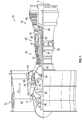
- FIG. 1 schematically illustrates a gas turbine engine 20.
- the gas turbine engine 20 is disclosed herein as a two-spool turbofan that generally incorporates a fan section 22, a compressor section 24, a combustor section 26 and a turbine section 28.
- Alternative engines might include other systems or features.
- the fan section 22 drives air along a bypass flow path B in a bypass duct, while the compressor section 24 drives air along a core flow path C for compression and communication into the combustor section 26 then expansion through the turbine section 28.
- FIG. 1 schematically illustrates a gas turbine engine 20.
- the gas turbine engine 20 is disclosed herein as a two-spool turbofan that generally incorporates a fan section 22, a compressor section 24, a combustor section 26 and a turbine section 28.
- Alternative engines might include other systems or features.
- the fan section 22 drives air along a bypass flow path B in a bypass duct
- the compressor section 24 drives air along a core flow path C for compression and communication into the combustor section 26
- the exemplary engine 20 generally includes a low speed spool 30 and a high speed spool 32 mounted for rotation about an engine central longitudinal axis A relative to an engine static structure 36 via several bearing systems 38. It should be understood that various bearing systems 38 at various locations may alternatively or additionally be provided, and the location of bearing systems 38 may be varied as appropriate to the application.
- the low speed spool 30 generally includes an inner shaft 40 that interconnects a fan 42, a low pressure compressor 44 and a low pressure turbine 46.
- the inner shaft 40 is connected to the fan 42 through a speed change mechanism, which in exemplary gas turbine engine 20 is illustrated as a geared architecture 48 to drive the fan 42 at a lower speed than the low speed spool 30.
- the high speed spool 32 includes an outer shaft 50 that interconnects a high pressure compressor 52 and high pressure turbine 54.
- a combustor 56 is arranged in exemplary gas turbine 20 between the high pressure compressor 52 and the high pressure turbine 54.
- An engine static structure 36 is arranged generally between the high pressure turbine 54 and the low pressure turbine 46.
- the engine static structure 36 further supports bearing systems 38 in the turbine section 28.
- the inner shaft 40 and the outer shaft 50 are concentric and rotate via bearing systems 38 about the engine central longitudinal axis A which is collinear with their longitudinal axes.
- each of the positions of the fan section 22, compressor section 24, combustor section 26, turbine section 28, and fan drive gear system 48 may be varied.
- gear system 48 may be located aft of combustor section 26 or even aft of turbine section 28, and fan section 22 may be positioned forward or aft of the location of gear system 48.
- the engine 20 in one example is a high-bypass geared aircraft engine.
- the engine 20 bypass ratio is greater than about six (6), with an example embodiment being greater than about ten (10)
- the geared architecture 48 is an epicyclical gear train, such as a planetary gear system or other gear system, with a gear reduction ratio of greater than about 2.3 and the low pressure turbine 46 has a pressure ratio that is greater than about five (5).
- the engine 20 bypass ratio is greater than about ten (10:1)
- the fan diameter is significantly larger than that of the low pressure compressor 44
- the low pressure turbine 46 has a pressure ratio that is greater than about five (5:1).
- Low pressure turbine 46 pressure ratio is pressure measured prior to inlet of low pressure turbine 46 as related to the pressure at the outlet of the low pressure turbine 46 prior to an exhaust nozzle.
- the geared architecture 48 may be an epicycle gear train, such as a planetary gear system or other gear system, with a gear reduction ratio of greater than about 2.3:1. It should be understood, however, that the above parameters are only exemplary of one embodiment of a geared architecture engine and that the present disclosure is applicable to other gas turbine engines including direct drive turbofans.
- the fan section 22 of the engine 20 is designed for a particular flight condition--typically cruise at about 0.8 Mach and about 35,000 feet (10,668 meters).
- 'TSFC' Thrust Specific Fuel Consumption
- Low fan pressure ratio is the pressure ratio across the fan blade alone, without a Fan Exit Guide Vane (“FEGV”) system.
- the low fan pressure ratio as disclosed herein according to one non-limiting embodiment is less than about 1.45.
- Low corrected fan tip speed is the actual fan tip speed in ft/sec divided by an industry standard temperature correction of [(Tram °R)/(518.7 °R)] 0.5 .
- the "Low corrected fan tip speed” as disclosed herein according to one non-limiting embodiment is less than about 1150 ft/second (350.5 m/sec).
- An embodiment of a low pressure compressor 44 includes one or more low compressor stators 60 arranged with one or more low compressor rotors 62.
- the low compressor rotors 62 are connected to the low speed spool 30 and rotate therewith.
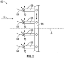
- FIG. 2 illustrates a low compressor stator row 60, with a plurality of stator vanes 64.
- Each of the stator vanes 64 is connected to a synchronization ring 66 via a vane arm 68.
- the assembly is configured such that when the synchronization ring 66 is rotated circumferentially about the engine central longitudinal axis A, each of the stator vanes 64 rotates about a vane axis 70, thus changing a leading edge incidence angle and a trailing edge discharge angle of the flow by varying a pitch of the vanes 64 relative to the core flow C.
- a linear actuator 76 is utilized to urge movement of the synchronization ring 66.
- the linear actuator 76 is a hydraulic actuator, and has a hydraulic piston 78 and linkage 80 connected to the synchronization ring 66 via an attachment clevis 82 or other feature of the synchronization ring 66.
- Linkage 80 between the hydraulic piston 78 and the attachment clevis 82 includes features (not shown) in linkage 80 that allow the linear actuator 76 to input an unchanging line of action while the synchronization ring 66 rotates about the engine axis A.
- one or more elements are integrally formed in a low pressure compressor case 72.
- One such component is the static or stationary hydraulic cylinder 84 of the linear actuator 76 in which the dynamic or axially translating hydraulic position 78 is located.
- pressurized hydraulic fluid passages 86 and 88 are formed integral to the low pressure compressor case 72.
- the hydraulic fluid passages 86, 88 are connected to the hydraulic cylinder 84 and urge movement of the hydraulic piston 78 via the controlled flow of pressurized hydraulic fluid into and out of the hydraulic cylinder 84. Movement of the hydraulic piston 78 in turn causes movement of the synchronization ring 66.
- the concept described utilizes a hydraulic actuator 76 that is perpendicular to engine axis A and generally parallel to the synchronization ring 66, alternate embodiments are possible. These include actuator orientation parallel to engine axis A and interfacing with a synchronization ring 66 through a bell-crank or other mechanical mechanism.
- the hydraulic cylinder 84 and the hydraulic fluid passages 86, 88 are integrally formed in the low pressure compressor case 72 and are located between an outer casing wall 90 and an inner casing wall 92.
- the low pressure compressor case 72 is formed via additive manufacturing, but in other embodiments other manufacturing processes may be utilized to integrally form the hydraulic cylinder 84 and the hydraulic fluid passages 86, 88 in the low pressure compressor case 72.
- the low pressure compressor case 72 may be formed from, for example, titanium, aluminum, steel and nickel alloys.
- a separate cylindrical sleeve 126 shown best in FIG. 4 , is inserted into the hydraulic cylinder 84 to provide an increased durability and wear resistance sealing surface for the hydraulic piston 78 to interact with.
- FIG. 5 Shown in FIG. 5 is a cross-sectional view of the linear actuator 76.
- the hydraulic cylinder 84 is embedded in the low pressure compressor case 72 extending from a closed cylinder end 94 to an open cylinder end 96 opposite the closed cylinder end 94.
- the hydraulic piston 78 is located in the hydraulic cylinder 84 and may include one or more piston seals 98 to seal between the hydraulic piston 78 and a cylinder wall 100.
- the linkage 80 is connected to and extends from the hydraulic piston 78 through a coverplate 102 affixed over the open cylinder end 86 by, for example, one or more coverplate fasteners 104. In some embodiments, one or more coverplate seals 106 between the coverplate 102 and the linkage 80.
- the integrally formed hydraulic fluid passages 86, 88 extend through the cylinder wall 100 to supply hydraulic fluid pressure to the hydraulic cylinder 84.
- a first hydraulic fluid passage 86 extends through the cylinder wall 100 at a first passage opening 108 into a first cylinder portion 110 defined between hydraulic piston 78 and the closed cylinder end 94, while a second hydraulic fluid passage 88 extends through the cylinder wall 100 at a second passage opening 112 into a second cylinder portion 114 defined between the hydraulic piston 78 and the coverplate 102.
- the hydraulic piston 78 are disposed in the cylinder sleeve 126 inserted into the hydraulic cylinder 84.
- material selection of sleeve 126 may provide enhanced wear properties. For example a case 72 fabricated using an aluminum alloy may desire a steel alloy sleeve 126. The sleeve 126 provides for ease of maintenance including removal and/or replacement of the hydraulic piston 78.
- a position sensor 116 such as a linear variable differential transformer (LVDT) or the like is positioned at the hydraulic cylinder 94 to detect a position of the hydraulic piston 78.
- the position sensor 116 is connected to an engine control system 118, which in some embodiments is a full authority digital engine control (FADEC) and provides the detected hydraulic piston 78 position to the engine control system 118.
- FADEC full authority digital engine control
- the hydraulic fluid passages 86, 88 are connected to a hydraulic control valve 120 at a hydraulic fluid reservoir 122, via one or more hydraulic fittings 124 at the low pressure compressor case 72.
- the hydraulic control valve 120 is connected to the engine control system 118 and is configured to direct hydraulic fluid along the hydraulic fluid passages 86, 88 in response to commands from the engine control system 118.
- the position sensor 116 provides feedback to the engine control system 118 regarding position of the hydraulic piston 78.
- the casing system disclosed herein having the hydraulic actuator cylinder 84 and/or hydraulic fluid passages 86, 88 embedded in the case has the technical effect of reducing component counts and thus providing a cost and weight reduction over traditional systems. Usage of external, exposed hydraulic fluid lines is reduced, thus reducing the risk of handling and maintenance damage to the thin-walled, highpressure hydraulic fluid lines.
- Such a system is additionally advantageous in configurations where multiple actuators are desired, or for small/expendable engines where scaling of components and associated limits make the combining of features and/or functions even more attractive.
- linear actuator 76 with embedded hydraulic cylinder 84 and hydraulic fluid passages 86, 88 for use in variable vane actuation with a synchronization ring 66 one skilled in the art will readily appreciate that the present disclosure may be applied to other actuation systems, for example, control of a kinematic system for a variable exhaust nozzle.
Landscapes
- Engineering & Computer Science (AREA)
- Mechanical Engineering (AREA)
- General Engineering & Computer Science (AREA)
- Manufacturing & Machinery (AREA)
- Chemical & Material Sciences (AREA)
- Materials Engineering (AREA)
- Control Of Turbines (AREA)
- Structures Of Non-Positive Displacement Pumps (AREA)
Abstract
Description
- Exemplary embodiments of the present disclosure pertain to the art of gas turbine engines. More particularly, the present disclosure relates to actuation systems to control movement of components of gas turbine engines.
- Gas turbine engines utilize structural cases inside which alternating rows of rotating blades and vanes are located. Linear actuators are fixed to the exterior of the case and are connected to some of the vanes, typically via a synchronization ring and other components to rotate the vanes as part of a variable vane system. Such variable vane systems are utilized in, for example, fan, low pressure compressor and high pressure compressor sections of the gas turbine engine.
- Such systems require considerable amounts of high pressure tubing to be secured to the case to convey hydraulic fluid to and from the hydraulic linear actuators. The tubing increasing the engine envelope, adds considerable weight to the gas turbine engine, and is exposed and may be easily damaged during manufacture and service of the gas turbine engine. In addition the hydraulic linear actuators contain a separate housing with resulting cost and weight.
- In a first embodiment, a casing assembly for a gas turbine engine includes a case having an outer case wall extending around a central axis, an inner case wall radially offset from the outer case wall, and one or more hydraulic fluid passages embedded in the case between the outer case wall and the inner case wall.
- Additionally or alternatively, in this or other embodiments a hydraulic cylinder for a linear actuator is embedded between the outer case wall and the inner case wall. The one or more hydraulic fluid passages are in fluid communication with the hydraulic cylinder.
- Additionally or alternatively, in this or other embodiments a hydraulic piston is located in the hydraulic cylinder. The hydraulic piston is movable in the hydraulic cylinder via hydraulic fluid flow into the hydraulic cylinder via the one or more hydraulic fluid passages.
- Additionally or alternatively, in this or other embodiments the hydraulic cylinder has a closed end and an open end opposite the closed end. A linkage is operably connected to the hydraulic piston and extends through a coverplate installed over the open end.
- Additionally or alternatively, in this or other embodiments the one or more hydraulic fluid passages are two hydraulic fluid passages and a first hydraulic fluid passage of the two hydraulic fluid passages extends into the hydraulic cylinder at a first axial side of the hydraulic piston, and a second hydraulic fluid passage of the two hydraulic fluid passages extends into the hydraulic cylinder at a second axial side of the hydraulic piston opposite the first side.
- Additionally or alternatively, in this or other embodiments a synchronization ring is located at the case and is operably connected to the hydraulic piston. Movement of the hydraulic piston urges circumferential movement of the synchronization ring about the central axis.
- Additionally or alternatively, in this or other embodiments a sleeve is located in the hydraulic cylinder between the hydraulic cylinder and the hydraulic piston.
- Additionally or alternatively, in this or other embodiments the case is formed via additive manufacturing.
- In a second embodiment, a variable pitch stator vane system includes a case extending about a central axis. The case includes an outer case wall, an inner case wall radially offset from the outer case wall, and one or more hydraulic fluid passages embedded in the case between the outer case wall and the inner case wall. A plurality of stator vanes are located radially inboard of the inner case wall. Each stator vane is rotatable about a central vane axis. An actuation unit is operably connected to the plurality of stator vanes and driven by hydraulic fluid through the one or more hydraulic fluid passages to urge rotation of the plurality of stator vanes about their respective central vane axes.
- Additionally or alternatively, in this or other embodiments the actuation unit includes a hydraulic cylinder for a linear actuator embedded between the outer case wall and the inner case wall. The one or more hydraulic fluid passages are in fluid communication with the hydraulic cylinder. A hydraulic piston is located in the hydraulic cylinder. The hydraulic piston is movable in the hydraulic cylinder via hydraulic fluid flow into the hydraulic cylinder via the one or more hydraulic fluid passages.
- Additionally or alternatively, in this or other embodiments the hydraulic cylinder has a closed end and an open end opposite the closed end. A linkage is operably connected to the hydraulic piston and extends through a coverplate installed over the open end.
- Additionally or alternatively, in this or other embodiments the one or more hydraulic fluid passages are two hydraulic fluid passages wherein a first hydraulic fluid passage of the two hydraulic fluid passages extends into the hydraulic cylinder at a first axial side of the hydraulic piston, and a second hydraulic fluid passage of the two hydraulic fluid passages extends into the hydraulic cylinder at a second axial side of the hydraulic piston opposite the first side.
- Additionally or alternatively, in this or other embodiments the plurality of stator vane are operably connected to the hydraulic piston via a synchronization ring disposed at the casing, wherein movement of the hydraulic piston urges circumferential movement of the synchronization ring about the central axis thus urging rotation of the plurality of stator vanes about their respective central vane axes.
- Additionally or alternatively, in this or other embodiments a sleeve is located in the hydraulic cylinder between the hydraulic cylinder and the hydraulic piston.
- Additionally or alternatively, in this or other embodiments the case is formed via additive manufacturing.
- Additionally or alternatively, in this or other embodiments the plurality of stator vanes are one of a plurality of fan stator vanes, compressor stator vanes or turbine stator vanes.
- Additionally or alternatively, in this or other embodiments the case extending about a central axis is the casing assembly of the first embodiment.
- In a third embodiment, a gas turbine engine includes a turbine section, a combustor section configured to drive rotation of the turbine, and a compressor section including a variable pitch stator vane system. The variable pitch stator vane system includes a case extending about a central axis having an outer case wall, an inner case wall radially offset from the outer case wall, and one or more hydraulic fluid passages embedded in the case between the outer case wall and the inner case wall. A plurality of stator vanes are located radially inboard of the inner case wall, each stator vane rotatable about a central vane axis. An actuation unit is operably connected to the plurality of stator vanes and is driven by hydraulic fluid through the one or more hydraulic fluid passages to urge rotation of the plurality of stator vanes about their respective central vane axes.
- Additionally or alternatively, in this or other embodiments the actuation unit includes a hydraulic cylinder for a linear actuator embedded between the outer case wall and the inner case wall. The one or more hydraulic fluid passages are in fluid communication with the hydraulic cylinder. A hydraulic piston is located in the hydraulic cylinder. The hydraulic piston is movable in the hydraulic cylinder via hydraulic fluid flow into the hydraulic cylinder via the one or more hydraulic fluid passages.
- Additionally or alternatively, in this or other embodiments the plurality of stator vanes are operably connected to the hydraulic piston via a synchronization ring located at the casing. Movement of the hydraulic piston urges circumferential movement of the synchronization ring about the central axis thus urging rotation of the plurality of stator vanes about their respective central vane axes.
- Additionally or alternatively, in this or other embodiments a sleeve is located in the hydraulic cylinder between the hydraulic cylinder and the hydraulic piston.
- Additionally or alternatively, in this or other embodiments the variable pitch stator vane system is the variable pitch stator vane system of the second embodiment.
- The following descriptions should not be considered limiting in any way. With reference to the accompanying drawings, like elements are numbered alike:
-
FIG. 1 is a partial cross-sectional view of a gas turbine engine; -
FIG. 2 is a schematic plan view of a variable pitch stator assembly of a gas turbine engine; -
FIG. 3 is a schematic partial plan view of a linear actuator arrangement for a variable pitch stator assembly of a gas turbine engine; -
FIG. 4 is a schematic partial cross-sectional view of a case with integrated components; and -
FIG. 5 is a schematic cross-sectional view of a linear actuator for a variable pitch stator assembly. - A detailed description of one or more embodiments of the disclosed apparatus and method are presented herein by way of exemplification and not limitation with reference to the Figures.
-
FIG. 1 schematically illustrates agas turbine engine 20. Thegas turbine engine 20 is disclosed herein as a two-spool turbofan that generally incorporates afan section 22, acompressor section 24, acombustor section 26 and aturbine section 28. Alternative engines might include other systems or features. Thefan section 22 drives air along a bypass flow path B in a bypass duct, while thecompressor section 24 drives air along a core flow path C for compression and communication into thecombustor section 26 then expansion through theturbine section 28. Although depicted as a two-spool turbofan gas turbine engine in the disclosed non-limiting embodiment, it should be understood that the concepts described herein are not limited to use with two-spool turbofans as the teachings may be applied to other types of turbine engines including three-spool architectures. - The
exemplary engine 20 generally includes alow speed spool 30 and ahigh speed spool 32 mounted for rotation about an engine central longitudinal axis A relative to an enginestatic structure 36 viaseveral bearing systems 38. It should be understood that various bearingsystems 38 at various locations may alternatively or additionally be provided, and the location of bearingsystems 38 may be varied as appropriate to the application. - The
low speed spool 30 generally includes aninner shaft 40 that interconnects afan 42, alow pressure compressor 44 and alow pressure turbine 46. Theinner shaft 40 is connected to thefan 42 through a speed change mechanism, which in exemplarygas turbine engine 20 is illustrated as a gearedarchitecture 48 to drive thefan 42 at a lower speed than thelow speed spool 30. Thehigh speed spool 32 includes anouter shaft 50 that interconnects ahigh pressure compressor 52 andhigh pressure turbine 54. Acombustor 56 is arranged inexemplary gas turbine 20 between thehigh pressure compressor 52 and thehigh pressure turbine 54. An enginestatic structure 36 is arranged generally between thehigh pressure turbine 54 and thelow pressure turbine 46. The enginestatic structure 36 furthersupports bearing systems 38 in theturbine section 28. Theinner shaft 40 and theouter shaft 50 are concentric and rotate via bearingsystems 38 about the engine central longitudinal axis A which is collinear with their longitudinal axes. - The core airflow is compressed by the
low pressure compressor 44 then thehigh pressure compressor 52, mixed and burned with fuel in thecombustor 56, then expanded over thehigh pressure turbine 54 andlow pressure turbine 46. Theturbines low speed spool 30 andhigh speed spool 32 in response to the expansion. It will be appreciated that each of the positions of thefan section 22,compressor section 24,combustor section 26,turbine section 28, and fandrive gear system 48 may be varied. For example,gear system 48 may be located aft ofcombustor section 26 or even aft ofturbine section 28, andfan section 22 may be positioned forward or aft of the location ofgear system 48. - The
engine 20 in one example is a high-bypass geared aircraft engine. In a further example, theengine 20 bypass ratio is greater than about six (6), with an example embodiment being greater than about ten (10), the gearedarchitecture 48 is an epicyclical gear train, such as a planetary gear system or other gear system, with a gear reduction ratio of greater than about 2.3 and thelow pressure turbine 46 has a pressure ratio that is greater than about five (5). In one disclosed embodiment, theengine 20 bypass ratio is greater than about ten (10:1), the fan diameter is significantly larger than that of thelow pressure compressor 44, and thelow pressure turbine 46 has a pressure ratio that is greater than about five (5:1).Low pressure turbine 46 pressure ratio is pressure measured prior to inlet oflow pressure turbine 46 as related to the pressure at the outlet of thelow pressure turbine 46 prior to an exhaust nozzle. The gearedarchitecture 48 may be an epicycle gear train, such as a planetary gear system or other gear system, with a gear reduction ratio of greater than about 2.3:1. It should be understood, however, that the above parameters are only exemplary of one embodiment of a geared architecture engine and that the present disclosure is applicable to other gas turbine engines including direct drive turbofans. - A significant amount of thrust is provided by the bypass flow B due to the high bypass ratio. The
fan section 22 of theengine 20 is designed for a particular flight condition--typically cruise at about 0.8 Mach and about 35,000 feet (10,668 meters). The flight condition of 0.8 Mach and 35,000 ft (10,668 meters), with the engine at its best fuel consumption--also known as "bucket cruise Thrust Specific Fuel Consumption ('TSFC')"--is the industry standard parameter of lbm of fuel being burned divided by lbf of thrust the engine produces at that minimum point. "Low fan pressure ratio" is the pressure ratio across the fan blade alone, without a Fan Exit Guide Vane ("FEGV") system. The low fan pressure ratio as disclosed herein according to one non-limiting embodiment is less than about 1.45. "Low corrected fan tip speed" is the actual fan tip speed in ft/sec divided by an industry standard temperature correction of [(Tram °R)/(518.7 °R)]0.5. The "Low corrected fan tip speed" as disclosed herein according to one non-limiting embodiment is less than about 1150 ft/second (350.5 m/sec). - An embodiment of a
low pressure compressor 44 includes one or morelow compressor stators 60 arranged with one or morelow compressor rotors 62. Thelow compressor rotors 62 are connected to thelow speed spool 30 and rotate therewith. -
FIG. 2 illustrates a lowcompressor stator row 60, with a plurality ofstator vanes 64. Each of thestator vanes 64 is connected to asynchronization ring 66 via avane arm 68. The assembly is configured such that when thesynchronization ring 66 is rotated circumferentially about the engine central longitudinal axis A, each of thestator vanes 64 rotates about avane axis 70, thus changing a leading edge incidence angle and a trailing edge discharge angle of the flow by varying a pitch of thevanes 64 relative to the core flow C. While described herein in the context of alow pressure compressor 44 of agas turbine engine 20, one skilled in the art will readily appreciate that the present disclosure may be similarly applied to synchronization ring and vane arrangements in other sections of thegas turbine engine 20, for example, thefan section 42, thelow pressure turbine 46, thehigh pressure compressor 52 or thehigh pressure turbine 54. - Referring to
FIG. 3 , alinear actuator 76 is utilized to urge movement of thesynchronization ring 66. Thelinear actuator 76 is a hydraulic actuator, and has ahydraulic piston 78 andlinkage 80 connected to thesynchronization ring 66 via anattachment clevis 82 or other feature of thesynchronization ring 66.Linkage 80 between thehydraulic piston 78 and theattachment clevis 82 includes features (not shown) inlinkage 80 that allow thelinear actuator 76 to input an unchanging line of action while thesynchronization ring 66 rotates about the engine axis A. As shown inFIG. 3 , one or more elements are integrally formed in a lowpressure compressor case 72. One such component is the static or stationaryhydraulic cylinder 84 of thelinear actuator 76 in which the dynamic or axially translatinghydraulic position 78 is located. Further, pressurized hydraulicfluid passages pressure compressor case 72. The hydraulicfluid passages hydraulic cylinder 84 and urge movement of thehydraulic piston 78 via the controlled flow of pressurized hydraulic fluid into and out of thehydraulic cylinder 84. Movement of thehydraulic piston 78 in turn causes movement of thesynchronization ring 66. While the concept described utilizes ahydraulic actuator 76 that is perpendicular to engine axis A and generally parallel to thesynchronization ring 66, alternate embodiments are possible. These include actuator orientation parallel to engine axis A and interfacing with asynchronization ring 66 through a bell-crank or other mechanical mechanism. - Referring to the cross-sectional view of
FIG. 4 , as stated above thehydraulic cylinder 84 and the hydraulicfluid passages pressure compressor case 72 and are located between anouter casing wall 90 and aninner casing wall 92. In some embodiments, the lowpressure compressor case 72 is formed via additive manufacturing, but in other embodiments other manufacturing processes may be utilized to integrally form thehydraulic cylinder 84 and the hydraulicfluid passages pressure compressor case 72. The lowpressure compressor case 72 may be formed from, for example, titanium, aluminum, steel and nickel alloys. In some embodiments, a separatecylindrical sleeve 126, shown best inFIG. 4 , is inserted into thehydraulic cylinder 84 to provide an increased durability and wear resistance sealing surface for thehydraulic piston 78 to interact with. - Shown in
FIG. 5 is a cross-sectional view of thelinear actuator 76. Thehydraulic cylinder 84 is embedded in the lowpressure compressor case 72 extending from aclosed cylinder end 94 to anopen cylinder end 96 opposite theclosed cylinder end 94. Thehydraulic piston 78 is located in thehydraulic cylinder 84 and may include one or more piston seals 98 to seal between thehydraulic piston 78 and acylinder wall 100. Thelinkage 80 is connected to and extends from thehydraulic piston 78 through acoverplate 102 affixed over theopen cylinder end 86 by, for example, one ormore coverplate fasteners 104. In some embodiments, one or more coverplate seals 106 between the coverplate 102 and thelinkage 80. The integrally formed hydraulicfluid passages cylinder wall 100 to supply hydraulic fluid pressure to thehydraulic cylinder 84. A firsthydraulic fluid passage 86 extends through thecylinder wall 100 at a first passage opening 108 into afirst cylinder portion 110 defined betweenhydraulic piston 78 and theclosed cylinder end 94, while a secondhydraulic fluid passage 88 extends through thecylinder wall 100 at a second passage opening 112 into asecond cylinder portion 114 defined between thehydraulic piston 78 and thecoverplate 102. Increasing the hydraulic fluid pressure in thefirst cylinder portion 110 moves thehydraulic piston 78 toward thecoverplate 102 thus extending thelinkage 80, while increasing the hydraulic fluid pressure in thesecond cylinder portion 114 moves thehydraulic piston 78 toward theclosed cylinder end 94 thus retracting thelinkage 80. In some embodiments, thehydraulic piston 78 are disposed in thecylinder sleeve 126 inserted into thehydraulic cylinder 84. Depending on the selection of materials for the lowpressure compressor case 72 andhydraulic piston 78, material selection ofsleeve 126 may provide enhanced wear properties. For example acase 72 fabricated using an aluminum alloy may desire asteel alloy sleeve 126. Thesleeve 126 provides for ease of maintenance including removal and/or replacement of thehydraulic piston 78. - Referring again to
FIG. 3 , in some embodiments, aposition sensor 116, such as a linear variable differential transformer (LVDT) or the like is positioned at thehydraulic cylinder 94 to detect a position of thehydraulic piston 78. Theposition sensor 116 is connected to anengine control system 118, which in some embodiments is a full authority digital engine control (FADEC) and provides the detectedhydraulic piston 78 position to theengine control system 118. - The hydraulic
fluid passages hydraulic control valve 120 at ahydraulic fluid reservoir 122, via one or morehydraulic fittings 124 at the lowpressure compressor case 72. Thehydraulic control valve 120 is connected to theengine control system 118 and is configured to direct hydraulic fluid along the hydraulicfluid passages engine control system 118. Theposition sensor 116 provides feedback to theengine control system 118 regarding position of thehydraulic piston 78. - The casing system disclosed herein having the
hydraulic actuator cylinder 84 and/or hydraulicfluid passages linear actuator 76 with embeddedhydraulic cylinder 84 and hydraulicfluid passages synchronization ring 66, one skilled in the art will readily appreciate that the present disclosure may be applied to other actuation systems, for example, control of a kinematic system for a variable exhaust nozzle. - The term "about" is intended to include the degree of error associated with measurement of the particular quantity based upon the equipment available at the time of filing the application. For example, "about" can include a range of ± 8% or 5%, or 2% of a given value.
- The terminology used herein is for the purpose of describing particular embodiments only and is not intended to be limiting of the present disclosure. As used herein, the singular forms "a", "an" and "the" are intended to include the plural forms as well, unless the context clearly indicates otherwise. It will be further understood that the terms "comprises" and/or "comprising," when used in this specification, specify the presence of stated features, integers, steps, operations, elements, and/or components, but do not preclude the presence or addition of one or more other features, integers, steps, operations, element components, and/or groups thereof.
- While the present disclosure has been described with reference to an exemplary embodiment or embodiments, it will be understood by those skilled in the art that various changes may be made and equivalents may be substituted for elements thereof without departing from the scope of the present disclosure. In addition, many modifications may be made to adapt a particular situation or material to the teachings of the present disclosure without departing from the scope thereof. Therefore, it is intended that the present disclosure not be limited to the particular embodiment disclosed as the best mode contemplated for carrying out this present disclosure, but that the present disclosure will include all embodiments falling within the scope of the claims.
- Further features of the disclosure, which may be combined with any of the previously discussed features, are given below in the following numbered clauses:
- 1. A casing assembly for a gas turbine engine, comprising a case including:
- an outer case wall extending around a central axis;
- an inner case wall radially offset from the outer case wall; and
- one or more hydraulic fluid passages embedded in the case between the outer case wall and the inner case wall.
- 2. The casing assembly of clause 1, further comprising a hydraulic cylinder for a linear actuator embedded between the outer case wall and the inner case wall, the one or more hydraulic fluid passages in fluid communication with the hydraulic cylinder.
- 3. The casing assembly of clause 2, further comprising a hydraulic piston disposed in the hydraulic cylinder, the hydraulic piston movable in the hydraulic cylinder via hydraulic fluid flow into the hydraulic cylinder via the one or more hydraulic fluid passages.
- 4. The casing assembly of clause 3, wherein the hydraulic cylinder has a closed end and an open end opposite the closed end, a linkage operably connected to the hydraulic piston extending through a coverplate installed over the open end.
- 5. The casing assembly of clause 3, wherein the one or more hydraulic fluid passages are two hydraulic fluid passages, wherein:
- a first hydraulic fluid passage of the two hydraulic fluid passages extends into the hydraulic cylinder at a first axial side of the hydraulic piston; and
- a second hydraulic fluid passage of the two hydraulic fluid passages extends into the hydraulic cylinder at a second axial side of the hydraulic piston opposite the first side.
- 6. The casing assembly of clause 3, further comprising a synchronization ring disposed at the case and operably connected to the hydraulic piston, wherein movement of the hydraulic piston urges circumferential movement of the synchronization ring about the central axis.
- 7. The casing assembly of clause 3, further comprising a sleeve disposed in the hydraulic cylinder between the hydraulic cylinder and the hydraulic piston.
- 8. The casing assembly of clause 1, wherein the case is formed via additive manufacturing.
- 9. A variable pitch stator vane system, comprising:
- a case extending about a central axis, including:
- an outer case wall;
- an inner case wall radially offset from the outer case wall; and
- one or more hydraulic fluid passages embedded in the case between the outer case wall and the inner case wall;
an actuation unit operably connected to the plurality of stator vanes and driven by hydraulic fluid through the one or more hydraulic fluid passages to urge rotation of the plurality of stator vanes about their respective central vane axes. - a case extending about a central axis, including:
- 10. The variable pitch stator vane system of clause 9, wherein the actuation unit comprises:
- a hydraulic cylinder for a linear actuator embedded between the outer case wall and the inner case wall, the one or more hydraulic fluid passages in fluid communication with the hydraulic cylinder; and
- a hydraulic piston disposed in the hydraulic cylinder, the hydraulic piston movable in the hydraulic cylinder via hydraulic fluid flow into the hydraulic cylinder via the one or more hydraulic fluid passages.
- 11. The variable pitch stator vane system of clause 10, wherein the hydraulic cylinder has a closed end and an open end opposite the closed end, a linkage operably connected to the hydraulic piston extending through a coverplate installed over the open end.
- 12. The variable pitch stator vane system of clause 10, wherein the one or more hydraulic fluid passages are two hydraulic fluid passages, wherein:
- a first hydraulic fluid passage of the two hydraulic fluid passages extends into the hydraulic cylinder at a first axial side of the hydraulic piston; and
- a second hydraulic fluid passage of the two hydraulic fluid passages extends into the hydraulic cylinder at a second axial side of the hydraulic piston opposite the first side.
- 13. The variable pitch stator vane system of clause 10, wherein the plurality of stator vanes are operably connected to the hydraulic piston via a synchronization ring disposed at the casing, wherein movement of the hydraulic piston urges circumferential movement of the synchronization ring about the central axis thus urging rotation of the plurality of stator vanes about their respective central vane axes.
- 14. The variable pitch stator vane system of clause 10, further comprising a sleeve disposed in the hydraulic cylinder between the hydraulic cylinder and the hydraulic piston.
- 15. The variable pitch stator vane system of clause 9, wherein the case is formed via additive manufacturing.
- 16. The variable pitch stator vane system of clause 9, wherein the plurality of stator vanes are one of a plurality of fan stator vanes, compressor stator vanes or turbine stator vanes.
- 17. A gas turbine engine, comprising:
- a turbine section;
- a combustor section configured to drive rotation of the turbine; and
- a compressor section, including:
- a variable pitch stator vane system, including:
a case extending about a central axis, having:
an outer case wall;
- a variable pitch stator vane system, including:
- an inner case wall radially offset from the outer case wall; and
a plurality of stator vanes disposed radially inboard of the inner case wall, each stator vane rotatable about a central vane axis; and
an actuation unit operably connected to the plurality of stator vanes and driven by hydraulic fluid through the one or more hydraulic fluid passages to urge rotation of the plurality of stator vanes about their respective central vane axes. - 18. The gas turbine engine of clause 17, wherein the actuation unit comprises:
- a hydraulic cylinder for a linear actuator embedded between the outer case wall and the inner case wall, the one or more hydraulic fluid passages in fluid communication with the hydraulic cylinder; and
- a hydraulic piston disposed in the hydraulic cylinder, the hydraulic piston movable in the hydraulic cylinder via hydraulic fluid flow into the hydraulic cylinder via the one or more hydraulic fluid passages.
- 19. The gas turbine engine of clause 18, wherein the plurality of stator vanes are operably connected to the hydraulic piston via a synchronization ring disposed at the casing, wherein movement of the hydraulic piston urges circumferential movement of the synchronization ring about the central axis thus urging rotation of the plurality of stator vanes about their respective central vane axes.
- 20. The gas turbine engine of clause 18, further comprising a sleeve disposed in the hydraulic cylinder between the hydraulic cylinder and the hydraulic piston.
Claims (12)
- A casing assembly for a gas turbine engine (20), comprising a case (72) including:an outer case wall (90) extending around a central axis (A);an inner case wall (92) radially offset from the outer case wall; andone or more hydraulic fluid passages (86, 88) embedded in the case between the outer case wall and the inner case wall.
- The casing assembly of claim 1, further comprising a hydraulic cylinder (84) for a linear actuator (76) embedded between the outer case wall (90) and the inner case wall (92), the one or more hydraulic fluid passages (86, 88) in fluid communication with the hydraulic cylinder.
- The casing assembly of claim 2, further comprising a hydraulic piston (78) disposed in the hydraulic cylinder (84), the hydraulic piston movable in the hydraulic cylinder via hydraulic fluid flow into the hydraulic cylinder via the one or more hydraulic fluid passages (86, 88).
- The casing assembly of claim 3, wherein the hydraulic cylinder (84) has a closed end (94) and an open end (96) opposite the closed end, a linkage (80) operably connected to the hydraulic piston (78) extending through a coverplate (102) installed over the open end.
- The casing assembly of claim 3 or 4, wherein the one or more hydraulic fluid passages (86, 88) are two hydraulic fluid passages, wherein:a first hydraulic fluid passage (86) of the two hydraulic fluid passages extends into the hydraulic cylinder (84) at a first axial side of the hydraulic piston; anda second hydraulic fluid passage (88) of the two hydraulic fluid passages extends into the hydraulic cylinder at a second axial side of the hydraulic piston opposite the first side.
- The casing assembly of claim 3, 4 or 5, further comprising a synchronization ring (66) disposed at the case (72) and operably connected to the hydraulic piston (78), wherein movement of the hydraulic piston urges circumferential movement of the synchronization ring about the central axis (A).
- The casing assembly of any of claim 3 to 6, further comprising a sleeve (126) disposed in the hydraulic cylinder (84) between the hydraulic cylinder and the hydraulic piston (78).
- The casing assembly of any preceding claim, wherein the case (72) is formed via additive manufacturing.
- A variable pitch stator vane system, comprising:the casing assembly of any preceding claim;a plurality of stator vanes (64) disposed radially inboard of the inner case wall (92), each stator vane rotatable about a central vane axis (70); andan actuation unit (76) operably connected to the plurality of stator vanes and driven by hydraulic fluid through the one or more hydraulic fluid passages (76, 78) to urge rotation of the plurality of stator vanes about their respective central vane axes.
- The variable pitch stator vane system of claim 9 when dependent on claim 6, wherein the plurality of stator vanes (64) are operably connected to the hydraulic piston (78) via the synchronization ring (66) disposed at the casing (72), wherein movement of the hydraulic piston urges circumferential movement of the synchronization ring about the central axis (A) thus urging rotation of the plurality of stator vanes about their respective central vane axes (70).
- The variable pitch stator vane system of claim 9 or 10, wherein the plurality of stator vanes (64) are one of a plurality of fan stator vanes, compressor stator vanes or turbine stator vanes.
- A gas turbine engine (20), comprising:a turbine section (28);a combustor section (26) configured to drive rotation of the turbine; anda compressor section (24), including:
the variable pitch stator vane system of claim 9 or 10.
Applications Claiming Priority (1)
| Application Number | Priority Date | Filing Date | Title |
|---|---|---|---|
| US16/181,564 US10961865B2 (en) | 2018-11-06 | 2018-11-06 | Gas turbine engine structure with integrated actuation features |
Publications (2)
| Publication Number | Publication Date |
|---|---|
| EP3650660A1 true EP3650660A1 (en) | 2020-05-13 |
| EP3650660B1 EP3650660B1 (en) | 2023-05-17 |
Family
ID=68470433
Family Applications (1)
| Application Number | Title | Priority Date | Filing Date |
|---|---|---|---|
| EP19207525.7A Active EP3650660B1 (en) | 2018-11-06 | 2019-11-06 | Gas turbine engine casing with embedded actuation features |
Country Status (2)
| Country | Link |
|---|---|
| US (1) | US10961865B2 (en) |
| EP (1) | EP3650660B1 (en) |
Families Citing this family (1)
| Publication number | Priority date | Publication date | Assignee | Title |
|---|---|---|---|---|
| US12491988B2 (en) * | 2022-08-12 | 2025-12-09 | General Electric Company | Controlling excitation loads associated with open rotor aeronautical engines |
Citations (2)
| Publication number | Priority date | Publication date | Assignee | Title |
|---|---|---|---|---|
| US20090165995A1 (en) * | 2007-12-27 | 2009-07-02 | Techspace Aero | Air-oil heat exchanger placed at the location of the air separator nose of a turbojet, and a turbojet including such an air-oil heat exchanger |
| US20100236213A1 (en) * | 2006-07-31 | 2010-09-23 | Jan Christopher Schilling | Method and apparatus for operating gas turbine engines |
Family Cites Families (13)
| Publication number | Priority date | Publication date | Assignee | Title |
|---|---|---|---|---|
| US2923459A (en) * | 1956-01-20 | 1960-02-02 | Thompson Ramo Wooldridge Inc | Vane positioning device |
| JPS597708A (en) * | 1982-07-07 | 1984-01-14 | Hitachi Ltd | Mounting angle variable device of stationary blade in axial flow machine |
| US5067323A (en) * | 1990-06-13 | 1991-11-26 | United Technologies Corporation | Three position actuator arrangement |
| US5261227A (en) * | 1992-11-24 | 1993-11-16 | General Electric Company | Variable specific thrust turbofan engine |
| FR2993631B1 (en) | 2012-07-18 | 2015-04-10 | Snecma | DEVICE FOR BLIND CONNECTION BETWEEN FLUID, ELECTRICAL OR SIMILAR POWER SUPPLIES AND A RECEIVER CONTROL MECHANISM |
| DE102012018649A1 (en) | 2012-09-20 | 2014-03-20 | Liebherr-Aerospace Lindenberg Gmbh | Klappenaktuator |
| US10052820B2 (en) | 2013-09-13 | 2018-08-21 | Made In Space, Inc. | Additive manufacturing of extended structures |
| US9919111B2 (en) | 2014-06-30 | 2018-03-20 | Elwha Llc | Active lubrication of penetrating devices |
| US10718359B2 (en) | 2015-08-21 | 2020-07-21 | Quality Manufacturing Inc. | Devices and systems for producing rotational actuation |
| FR3045755B1 (en) | 2015-12-22 | 2019-06-21 | Foundation Brakes France | METHOD FOR MANUFACTURING A DISC BRAKE CALIPER BODY COMPRISING A PRINTING MANUFACTURING OPERATION AND IN PARTICULAR A LASER ADDITIVE MANUFACTURE |
| GB2555578B (en) | 2016-10-27 | 2022-05-25 | Alcon Components Ltd | Hydraulic fluid ducts for disc brake calipers and method of manufacture thereof |
| DK3318768T3 (en) * | 2016-11-04 | 2021-10-18 | Pistonpower Aps | HYDRAULIC ACTUATOR WITH INSERT PRESSURE AMPLIFIER |
| US10174763B1 (en) * | 2018-08-02 | 2019-01-08 | Florida Turbine Technologies, Inc | Variable pitch fan for gas turbine engine |
-
2018
- 2018-11-06 US US16/181,564 patent/US10961865B2/en active Active
-
2019
- 2019-11-06 EP EP19207525.7A patent/EP3650660B1/en active Active
Patent Citations (2)
| Publication number | Priority date | Publication date | Assignee | Title |
|---|---|---|---|---|
| US20100236213A1 (en) * | 2006-07-31 | 2010-09-23 | Jan Christopher Schilling | Method and apparatus for operating gas turbine engines |
| US20090165995A1 (en) * | 2007-12-27 | 2009-07-02 | Techspace Aero | Air-oil heat exchanger placed at the location of the air separator nose of a turbojet, and a turbojet including such an air-oil heat exchanger |
Also Published As
| Publication number | Publication date |
|---|---|
| US10961865B2 (en) | 2021-03-30 |
| EP3650660B1 (en) | 2023-05-17 |
| US20200141264A1 (en) | 2020-05-07 |
Similar Documents
| Publication | Publication Date | Title |
|---|---|---|
| EP3677818B1 (en) | Cantilevered hydrostatic advanced low leakage seal | |
| US11092030B2 (en) | Adaptive case for a gas turbine engine | |
| EP4053383B1 (en) | Piston ring shuttle carrier | |
| US10822983B2 (en) | Hydrostatic seal with abradable teeth for gas turbine engine | |
| EP3760838B1 (en) | Gas turbine variable vane system and method | |
| EP3789588B1 (en) | Hydrostatic seal aligned with rotor rotation | |
| EP3789589B1 (en) | Hydrostatic seal | |
| EP3677816B1 (en) | Articulating cantilevered hydrostatic seal | |
| EP3786418A1 (en) | Hydrostatic seal with seal stops | |
| EP3623584B1 (en) | Set screw gap control between fixed and variable vanes | |
| EP3650660B1 (en) | Gas turbine engine casing with embedded actuation features | |
| EP3910166A1 (en) | Radial seal arrangement | |
| EP3502455B1 (en) | Bleed valve system | |
| EP4386179A1 (en) | Gas turbine engine with split helical piston seal | |
| EP3611358B1 (en) | Bleed valve actuation system | |
| US11181004B2 (en) | Confinement of a rope seal about a passage using a backing plate | |
| EP4455454A2 (en) | Shared load path blade outer air seal | |
| EP4461930A1 (en) | Radially retractable outer air seal | |
| EP4455453A2 (en) | Failsafe blade outer airseal retention | |
| EP3907389B1 (en) | Gas turbine compressor radial door bleed valve | |
| US20250345982A1 (en) | Gas turbine engine with split helical piston seal | |
| EP4556684A1 (en) | Slider seal for gas turbine engine | |
| EP3564491B1 (en) | Variable vane actuation system with nested direct vane angle measurement shaft | |
| US10570852B2 (en) | Moveable exhaust plug liner |
Legal Events
| Date | Code | Title | Description |
|---|---|---|---|
| PUAI | Public reference made under article 153(3) epc to a published international application that has entered the european phase |
Free format text: ORIGINAL CODE: 0009012 |
|
| STAA | Information on the status of an ep patent application or granted ep patent |
Free format text: STATUS: THE APPLICATION HAS BEEN PUBLISHED |
|
| AK | Designated contracting states |
Kind code of ref document: A1 Designated state(s): AL AT BE BG CH CY CZ DE DK EE ES FI FR GB GR HR HU IE IS IT LI LT LU LV MC MK MT NL NO PL PT RO RS SE SI SK SM TR |
|
| AX | Request for extension of the european patent |
Extension state: BA ME |
|
| STAA | Information on the status of an ep patent application or granted ep patent |
Free format text: STATUS: REQUEST FOR EXAMINATION WAS MADE |
|
| 17P | Request for examination filed |
Effective date: 20201113 |
|
| RBV | Designated contracting states (corrected) |
Designated state(s): AL AT BE BG CH CY CZ DE DK EE ES FI FR GB GR HR HU IE IS IT LI LT LU LV MC MK MT NL NO PL PT RO RS SE SI SK SM TR |
|
| RAP1 | Party data changed (applicant data changed or rights of an application transferred) |
Owner name: RAYTHEON TECHNOLOGIES CORPORATION |
|
| GRAP | Despatch of communication of intention to grant a patent |
Free format text: ORIGINAL CODE: EPIDOSNIGR1 |
|
| STAA | Information on the status of an ep patent application or granted ep patent |
Free format text: STATUS: GRANT OF PATENT IS INTENDED |
|
| INTG | Intention to grant announced |
Effective date: 20211103 |
|
| RIN1 | Information on inventor provided before grant (corrected) |
Inventor name: ROBERGE, GARY D. |
|
| GRAJ | Information related to disapproval of communication of intention to grant by the applicant or resumption of examination proceedings by the epo deleted |
Free format text: ORIGINAL CODE: EPIDOSDIGR1 |
|
| STAA | Information on the status of an ep patent application or granted ep patent |
Free format text: STATUS: REQUEST FOR EXAMINATION WAS MADE |
|
| INTC | Intention to grant announced (deleted) | ||
| GRAP | Despatch of communication of intention to grant a patent |
Free format text: ORIGINAL CODE: EPIDOSNIGR1 |
|
| STAA | Information on the status of an ep patent application or granted ep patent |
Free format text: STATUS: GRANT OF PATENT IS INTENDED |
|
| INTG | Intention to grant announced |
Effective date: 20220425 |
|
| GRAJ | Information related to disapproval of communication of intention to grant by the applicant or resumption of examination proceedings by the epo deleted |
Free format text: ORIGINAL CODE: EPIDOSDIGR1 |
|
| STAA | Information on the status of an ep patent application or granted ep patent |
Free format text: STATUS: REQUEST FOR EXAMINATION WAS MADE |
|
| INTC | Intention to grant announced (deleted) | ||
| GRAP | Despatch of communication of intention to grant a patent |
Free format text: ORIGINAL CODE: EPIDOSNIGR1 |
|
| STAA | Information on the status of an ep patent application or granted ep patent |
Free format text: STATUS: GRANT OF PATENT IS INTENDED |
|
| INTG | Intention to grant announced |
Effective date: 20221202 |
|
| GRAS | Grant fee paid |
Free format text: ORIGINAL CODE: EPIDOSNIGR3 |
|
| GRAA | (expected) grant |
Free format text: ORIGINAL CODE: 0009210 |
|
| STAA | Information on the status of an ep patent application or granted ep patent |
Free format text: STATUS: THE PATENT HAS BEEN GRANTED |
|
| AK | Designated contracting states |
Kind code of ref document: B1 Designated state(s): AL AT BE BG CH CY CZ DE DK EE ES FI FR GB GR HR HU IE IS IT LI LT LU LV MC MK MT NL NO PL PT RO RS SE SI SK SM TR |
|
| REG | Reference to a national code |
Ref country code: GB Ref legal event code: FG4D |
|
| REG | Reference to a national code |
Ref country code: DE Ref legal event code: R096 Ref document number: 602019029034 Country of ref document: DE |
|
| REG | Reference to a national code |
Ref country code: CH Ref legal event code: EP |
|
| REG | Reference to a national code |
Ref country code: IE Ref legal event code: FG4D |
|
| REG | Reference to a national code |
Ref country code: AT Ref legal event code: REF Ref document number: 1568444 Country of ref document: AT Kind code of ref document: T Effective date: 20230615 |
|
| REG | Reference to a national code |
Ref country code: LT Ref legal event code: MG9D |
|
| REG | Reference to a national code |
Ref country code: NL Ref legal event code: MP Effective date: 20230517 |
|
| REG | Reference to a national code |
Ref country code: AT Ref legal event code: MK05 Ref document number: 1568444 Country of ref document: AT Kind code of ref document: T Effective date: 20230517 |
|
| PG25 | Lapsed in a contracting state [announced via postgrant information from national office to epo] |
Ref country code: SE Free format text: LAPSE BECAUSE OF FAILURE TO SUBMIT A TRANSLATION OF THE DESCRIPTION OR TO PAY THE FEE WITHIN THE PRESCRIBED TIME-LIMIT Effective date: 20230517 Ref country code: PT Free format text: LAPSE BECAUSE OF FAILURE TO SUBMIT A TRANSLATION OF THE DESCRIPTION OR TO PAY THE FEE WITHIN THE PRESCRIBED TIME-LIMIT Effective date: 20230918 Ref country code: NO Free format text: LAPSE BECAUSE OF FAILURE TO SUBMIT A TRANSLATION OF THE DESCRIPTION OR TO PAY THE FEE WITHIN THE PRESCRIBED TIME-LIMIT Effective date: 20230817 Ref country code: NL Free format text: LAPSE BECAUSE OF FAILURE TO SUBMIT A TRANSLATION OF THE DESCRIPTION OR TO PAY THE FEE WITHIN THE PRESCRIBED TIME-LIMIT Effective date: 20230517 Ref country code: ES Free format text: LAPSE BECAUSE OF FAILURE TO SUBMIT A TRANSLATION OF THE DESCRIPTION OR TO PAY THE FEE WITHIN THE PRESCRIBED TIME-LIMIT Effective date: 20230517 Ref country code: AT Free format text: LAPSE BECAUSE OF FAILURE TO SUBMIT A TRANSLATION OF THE DESCRIPTION OR TO PAY THE FEE WITHIN THE PRESCRIBED TIME-LIMIT Effective date: 20230517 |
|
| RAP4 | Party data changed (patent owner data changed or rights of a patent transferred) |
Owner name: RTX CORPORATION |
|
| PG25 | Lapsed in a contracting state [announced via postgrant information from national office to epo] |
Ref country code: RS Free format text: LAPSE BECAUSE OF FAILURE TO SUBMIT A TRANSLATION OF THE DESCRIPTION OR TO PAY THE FEE WITHIN THE PRESCRIBED TIME-LIMIT Effective date: 20230517 Ref country code: PL Free format text: LAPSE BECAUSE OF FAILURE TO SUBMIT A TRANSLATION OF THE DESCRIPTION OR TO PAY THE FEE WITHIN THE PRESCRIBED TIME-LIMIT Effective date: 20230517 Ref country code: LV Free format text: LAPSE BECAUSE OF FAILURE TO SUBMIT A TRANSLATION OF THE DESCRIPTION OR TO PAY THE FEE WITHIN THE PRESCRIBED TIME-LIMIT Effective date: 20230517 Ref country code: LT Free format text: LAPSE BECAUSE OF FAILURE TO SUBMIT A TRANSLATION OF THE DESCRIPTION OR TO PAY THE FEE WITHIN THE PRESCRIBED TIME-LIMIT Effective date: 20230517 Ref country code: IS Free format text: LAPSE BECAUSE OF FAILURE TO SUBMIT A TRANSLATION OF THE DESCRIPTION OR TO PAY THE FEE WITHIN THE PRESCRIBED TIME-LIMIT Effective date: 20230917 Ref country code: HR Free format text: LAPSE BECAUSE OF FAILURE TO SUBMIT A TRANSLATION OF THE DESCRIPTION OR TO PAY THE FEE WITHIN THE PRESCRIBED TIME-LIMIT Effective date: 20230517 Ref country code: GR Free format text: LAPSE BECAUSE OF FAILURE TO SUBMIT A TRANSLATION OF THE DESCRIPTION OR TO PAY THE FEE WITHIN THE PRESCRIBED TIME-LIMIT Effective date: 20230818 |
|
| PG25 | Lapsed in a contracting state [announced via postgrant information from national office to epo] |
Ref country code: FI Free format text: LAPSE BECAUSE OF FAILURE TO SUBMIT A TRANSLATION OF THE DESCRIPTION OR TO PAY THE FEE WITHIN THE PRESCRIBED TIME-LIMIT Effective date: 20230517 |
|
| PG25 | Lapsed in a contracting state [announced via postgrant information from national office to epo] |
Ref country code: SK Free format text: LAPSE BECAUSE OF FAILURE TO SUBMIT A TRANSLATION OF THE DESCRIPTION OR TO PAY THE FEE WITHIN THE PRESCRIBED TIME-LIMIT Effective date: 20230517 |
|
| PG25 | Lapsed in a contracting state [announced via postgrant information from national office to epo] |
Ref country code: SM Free format text: LAPSE BECAUSE OF FAILURE TO SUBMIT A TRANSLATION OF THE DESCRIPTION OR TO PAY THE FEE WITHIN THE PRESCRIBED TIME-LIMIT Effective date: 20230517 Ref country code: SK Free format text: LAPSE BECAUSE OF FAILURE TO SUBMIT A TRANSLATION OF THE DESCRIPTION OR TO PAY THE FEE WITHIN THE PRESCRIBED TIME-LIMIT Effective date: 20230517 Ref country code: RO Free format text: LAPSE BECAUSE OF FAILURE TO SUBMIT A TRANSLATION OF THE DESCRIPTION OR TO PAY THE FEE WITHIN THE PRESCRIBED TIME-LIMIT Effective date: 20230517 Ref country code: EE Free format text: LAPSE BECAUSE OF FAILURE TO SUBMIT A TRANSLATION OF THE DESCRIPTION OR TO PAY THE FEE WITHIN THE PRESCRIBED TIME-LIMIT Effective date: 20230517 Ref country code: DK Free format text: LAPSE BECAUSE OF FAILURE TO SUBMIT A TRANSLATION OF THE DESCRIPTION OR TO PAY THE FEE WITHIN THE PRESCRIBED TIME-LIMIT Effective date: 20230517 Ref country code: CZ Free format text: LAPSE BECAUSE OF FAILURE TO SUBMIT A TRANSLATION OF THE DESCRIPTION OR TO PAY THE FEE WITHIN THE PRESCRIBED TIME-LIMIT Effective date: 20230517 |
|
| REG | Reference to a national code |
Ref country code: DE Ref legal event code: R097 Ref document number: 602019029034 Country of ref document: DE |
|
| PLBE | No opposition filed within time limit |
Free format text: ORIGINAL CODE: 0009261 |
|
| STAA | Information on the status of an ep patent application or granted ep patent |
Free format text: STATUS: NO OPPOSITION FILED WITHIN TIME LIMIT |
|
| 26N | No opposition filed |
Effective date: 20240220 |
|
| PG25 | Lapsed in a contracting state [announced via postgrant information from national office to epo] |
Ref country code: SI Free format text: LAPSE BECAUSE OF FAILURE TO SUBMIT A TRANSLATION OF THE DESCRIPTION OR TO PAY THE FEE WITHIN THE PRESCRIBED TIME-LIMIT Effective date: 20230517 |
|
| PG25 | Lapsed in a contracting state [announced via postgrant information from national office to epo] |
Ref country code: SI Free format text: LAPSE BECAUSE OF FAILURE TO SUBMIT A TRANSLATION OF THE DESCRIPTION OR TO PAY THE FEE WITHIN THE PRESCRIBED TIME-LIMIT Effective date: 20230517 Ref country code: IT Free format text: LAPSE BECAUSE OF FAILURE TO SUBMIT A TRANSLATION OF THE DESCRIPTION OR TO PAY THE FEE WITHIN THE PRESCRIBED TIME-LIMIT Effective date: 20230517 |
|
| REG | Reference to a national code |
Ref country code: CH Ref legal event code: PL |
|
| PG25 | Lapsed in a contracting state [announced via postgrant information from national office to epo] |
Ref country code: MC Free format text: LAPSE BECAUSE OF FAILURE TO SUBMIT A TRANSLATION OF THE DESCRIPTION OR TO PAY THE FEE WITHIN THE PRESCRIBED TIME-LIMIT Effective date: 20230517 |
|
| PG25 | Lapsed in a contracting state [announced via postgrant information from national office to epo] |
Ref country code: LU Free format text: LAPSE BECAUSE OF NON-PAYMENT OF DUE FEES Effective date: 20231106 |
|
| PG25 | Lapsed in a contracting state [announced via postgrant information from national office to epo] |
Ref country code: CH Free format text: LAPSE BECAUSE OF NON-PAYMENT OF DUE FEES Effective date: 20231130 |
|
| PG25 | Lapsed in a contracting state [announced via postgrant information from national office to epo] |
Ref country code: MC Free format text: LAPSE BECAUSE OF FAILURE TO SUBMIT A TRANSLATION OF THE DESCRIPTION OR TO PAY THE FEE WITHIN THE PRESCRIBED TIME-LIMIT Effective date: 20230517 Ref country code: LU Free format text: LAPSE BECAUSE OF NON-PAYMENT OF DUE FEES Effective date: 20231106 Ref country code: CH Free format text: LAPSE BECAUSE OF NON-PAYMENT OF DUE FEES Effective date: 20231130 |
|
| REG | Reference to a national code |
Ref country code: BE Ref legal event code: MM Effective date: 20231130 |
|
| REG | Reference to a national code |
Ref country code: IE Ref legal event code: MM4A |
|
| PG25 | Lapsed in a contracting state [announced via postgrant information from national office to epo] |
Ref country code: IE Free format text: LAPSE BECAUSE OF NON-PAYMENT OF DUE FEES Effective date: 20231106 |
|
| PG25 | Lapsed in a contracting state [announced via postgrant information from national office to epo] |
Ref country code: BE Free format text: LAPSE BECAUSE OF NON-PAYMENT OF DUE FEES Effective date: 20231130 |
|
| PG25 | Lapsed in a contracting state [announced via postgrant information from national office to epo] |
Ref country code: IE Free format text: LAPSE BECAUSE OF NON-PAYMENT OF DUE FEES Effective date: 20231106 Ref country code: BE Free format text: LAPSE BECAUSE OF NON-PAYMENT OF DUE FEES Effective date: 20231130 |
|
| PG25 | Lapsed in a contracting state [announced via postgrant information from national office to epo] |
Ref country code: BG Free format text: LAPSE BECAUSE OF FAILURE TO SUBMIT A TRANSLATION OF THE DESCRIPTION OR TO PAY THE FEE WITHIN THE PRESCRIBED TIME-LIMIT Effective date: 20230517 |
|
| PG25 | Lapsed in a contracting state [announced via postgrant information from national office to epo] |
Ref country code: BG Free format text: LAPSE BECAUSE OF FAILURE TO SUBMIT A TRANSLATION OF THE DESCRIPTION OR TO PAY THE FEE WITHIN THE PRESCRIBED TIME-LIMIT Effective date: 20230517 |
|
| PG25 | Lapsed in a contracting state [announced via postgrant information from national office to epo] |
Ref country code: CY Free format text: LAPSE BECAUSE OF FAILURE TO SUBMIT A TRANSLATION OF THE DESCRIPTION OR TO PAY THE FEE WITHIN THE PRESCRIBED TIME-LIMIT; INVALID AB INITIO Effective date: 20191106 |
|
| PG25 | Lapsed in a contracting state [announced via postgrant information from national office to epo] |
Ref country code: HU Free format text: LAPSE BECAUSE OF FAILURE TO SUBMIT A TRANSLATION OF THE DESCRIPTION OR TO PAY THE FEE WITHIN THE PRESCRIBED TIME-LIMIT; INVALID AB INITIO Effective date: 20191106 |
|
| REG | Reference to a national code |
Ref country code: DE Ref legal event code: R081 Ref document number: 602019029034 Country of ref document: DE Owner name: RTX CORPORATION (N.D.GES.D. STAATES DELAWARE),, US Free format text: FORMER OWNER: RAYTHEON TECHNOLOGIES CORPORATION, FARMINGTON, CT, US |
|
| PG25 | Lapsed in a contracting state [announced via postgrant information from national office to epo] |
Ref country code: TR Free format text: LAPSE BECAUSE OF FAILURE TO SUBMIT A TRANSLATION OF THE DESCRIPTION OR TO PAY THE FEE WITHIN THE PRESCRIBED TIME-LIMIT Effective date: 20230517 |
|
| PGFP | Annual fee paid to national office [announced via postgrant information from national office to epo] |
Ref country code: DE Payment date: 20251022 Year of fee payment: 7 |
|
| PGFP | Annual fee paid to national office [announced via postgrant information from national office to epo] |
Ref country code: GB Payment date: 20251023 Year of fee payment: 7 |
|
| PGFP | Annual fee paid to national office [announced via postgrant information from national office to epo] |
Ref country code: FR Payment date: 20251022 Year of fee payment: 7 |
|
| P01 | Opt-out of the competence of the unified patent court (upc) registered |
Free format text: CASE NUMBER: UPC_APP_0019309_3650660/2025 Effective date: 20251223 |