EP3650638A1 - Mistuned rotors for gas turbine engines and methods for manufacture - Google Patents
Mistuned rotors for gas turbine engines and methods for manufacture Download PDFInfo
- Publication number
- EP3650638A1 EP3650638A1 EP19207318.7A EP19207318A EP3650638A1 EP 3650638 A1 EP3650638 A1 EP 3650638A1 EP 19207318 A EP19207318 A EP 19207318A EP 3650638 A1 EP3650638 A1 EP 3650638A1
- Authority
- EP
- European Patent Office
- Prior art keywords
- rotor
- airfoil
- airfoils
- shape
- span
- Prior art date
- Legal status (The legal status is an assumption and is not a legal conclusion. Google has not performed a legal analysis and makes no representation as to the accuracy of the status listed.)
- Granted
Links
Images







Classifications
-
- F—MECHANICAL ENGINEERING; LIGHTING; HEATING; WEAPONS; BLASTING
- F01—MACHINES OR ENGINES IN GENERAL; ENGINE PLANTS IN GENERAL; STEAM ENGINES
- F01D—NON-POSITIVE DISPLACEMENT MACHINES OR ENGINES, e.g. STEAM TURBINES
- F01D5/00—Blades; Blade-carrying members; Heating, heat-insulating, cooling or antivibration means on the blades or the members
- F01D5/02—Blade-carrying members, e.g. rotors
- F01D5/10—Anti- vibration means
-
- F—MECHANICAL ENGINEERING; LIGHTING; HEATING; WEAPONS; BLASTING
- F01—MACHINES OR ENGINES IN GENERAL; ENGINE PLANTS IN GENERAL; STEAM ENGINES
- F01D—NON-POSITIVE DISPLACEMENT MACHINES OR ENGINES, e.g. STEAM TURBINES
- F01D5/00—Blades; Blade-carrying members; Heating, heat-insulating, cooling or antivibration means on the blades or the members
- F01D5/12—Blades
- F01D5/14—Form or construction
- F01D5/16—Form or construction for counteracting blade vibration
-
- B—PERFORMING OPERATIONS; TRANSPORTING
- B23—MACHINE TOOLS; METAL-WORKING NOT OTHERWISE PROVIDED FOR
- B23P—METAL-WORKING NOT OTHERWISE PROVIDED FOR; COMBINED OPERATIONS; UNIVERSAL MACHINE TOOLS
- B23P15/00—Making specific metal objects by operations not covered by a single other subclass or a group in this subclass
- B23P15/04—Making specific metal objects by operations not covered by a single other subclass or a group in this subclass turbine or like blades from several pieces
-
- F—MECHANICAL ENGINEERING; LIGHTING; HEATING; WEAPONS; BLASTING
- F01—MACHINES OR ENGINES IN GENERAL; ENGINE PLANTS IN GENERAL; STEAM ENGINES
- F01D—NON-POSITIVE DISPLACEMENT MACHINES OR ENGINES, e.g. STEAM TURBINES
- F01D5/00—Blades; Blade-carrying members; Heating, heat-insulating, cooling or antivibration means on the blades or the members
- F01D5/12—Blades
- F01D5/14—Form or construction
- F01D5/141—Shape, i.e. outer, aerodynamic form
-
- F—MECHANICAL ENGINEERING; LIGHTING; HEATING; WEAPONS; BLASTING
- F04—POSITIVE - DISPLACEMENT MACHINES FOR LIQUIDS; PUMPS FOR LIQUIDS OR ELASTIC FLUIDS
- F04D—NON-POSITIVE-DISPLACEMENT PUMPS
- F04D29/00—Details, component parts, or accessories
- F04D29/26—Rotors specially for elastic fluids
- F04D29/32—Rotors specially for elastic fluids for axial flow pumps
- F04D29/321—Rotors specially for elastic fluids for axial flow pumps for axial flow compressors
- F04D29/324—Blades
-
- F—MECHANICAL ENGINEERING; LIGHTING; HEATING; WEAPONS; BLASTING
- F04—POSITIVE - DISPLACEMENT MACHINES FOR LIQUIDS; PUMPS FOR LIQUIDS OR ELASTIC FLUIDS
- F04D—NON-POSITIVE-DISPLACEMENT PUMPS
- F04D29/00—Details, component parts, or accessories
- F04D29/66—Combating cavitation, whirls, noise, vibration or the like; Balancing
- F04D29/661—Combating cavitation, whirls, noise, vibration or the like; Balancing especially adapted for elastic fluid pumps
- F04D29/666—Combating cavitation, whirls, noise, vibration or the like; Balancing especially adapted for elastic fluid pumps by means of rotor construction or layout, e.g. unequal distribution of blades or vanes
-
- B—PERFORMING OPERATIONS; TRANSPORTING
- B23—MACHINE TOOLS; METAL-WORKING NOT OTHERWISE PROVIDED FOR
- B23P—METAL-WORKING NOT OTHERWISE PROVIDED FOR; COMBINED OPERATIONS; UNIVERSAL MACHINE TOOLS
- B23P2700/00—Indexing scheme relating to the articles being treated, e.g. manufactured, repaired, assembled, connected or other operations covered in the subgroups
- B23P2700/01—Aircraft parts
-
- B—PERFORMING OPERATIONS; TRANSPORTING
- B23—MACHINE TOOLS; METAL-WORKING NOT OTHERWISE PROVIDED FOR
- B23P—METAL-WORKING NOT OTHERWISE PROVIDED FOR; COMBINED OPERATIONS; UNIVERSAL MACHINE TOOLS
- B23P2700/00—Indexing scheme relating to the articles being treated, e.g. manufactured, repaired, assembled, connected or other operations covered in the subgroups
- B23P2700/50—Other automobile vehicle parts, i.e. manufactured in assembly lines
-
- F—MECHANICAL ENGINEERING; LIGHTING; HEATING; WEAPONS; BLASTING
- F05—INDEXING SCHEMES RELATING TO ENGINES OR PUMPS IN VARIOUS SUBCLASSES OF CLASSES F01-F04
- F05D—INDEXING SCHEME FOR ASPECTS RELATING TO NON-POSITIVE-DISPLACEMENT MACHINES OR ENGINES, GAS-TURBINES OR JET-PROPULSION PLANTS
- F05D2260/00—Function
- F05D2260/96—Preventing, counteracting or reducing vibration or noise
- F05D2260/961—Preventing, counteracting or reducing vibration or noise by mistuning rotor blades or stator vanes with irregular interblade spacing, airfoil shape
-
- Y—GENERAL TAGGING OF NEW TECHNOLOGICAL DEVELOPMENTS; GENERAL TAGGING OF CROSS-SECTIONAL TECHNOLOGIES SPANNING OVER SEVERAL SECTIONS OF THE IPC; TECHNICAL SUBJECTS COVERED BY FORMER USPC CROSS-REFERENCE ART COLLECTIONS [XRACs] AND DIGESTS
- Y02—TECHNOLOGIES OR APPLICATIONS FOR MITIGATION OR ADAPTATION AGAINST CLIMATE CHANGE
- Y02T—CLIMATE CHANGE MITIGATION TECHNOLOGIES RELATED TO TRANSPORTATION
- Y02T50/00—Aeronautics or air transport
- Y02T50/60—Efficient propulsion technologies, e.g. for aircraft
Definitions
- each airfoil of the plurality of airfoils has a pressure side surface shape based on an operating state of the rotor and the suction side of each airfoil of the plurality of airfoils has a suction side surface shape based on the operating state of the rotor.
- Each airfoil of the plurality of airfoils has the same suction side surface shape between 10% and 90% of the chord and between 80% and 100% of the span at a first operating state of the rotor.
- the airfoil manufacturing system 300 ensures that the airfoils 112, 114 of the rotor 102 are manufactured by the manufacturing system 106 ( FIG. 1 ) to reduce susceptibility to flutter, while also reducing acoustic energy. Thus, the airfoil manufacturing system 300 generates the mistuned rotor 102 for use with the gas turbine engine 104.
- ⁇ T is the total camber of the airfoil 112 at the particular span; ⁇ 1 is the inlet metal angle in degrees; and ⁇ 2 is the exit metal angle in degrees.
- the airfoil 114 has the position 230 or location of local maximum thickness LMT, which is defined as a ratio of the first arc distance S Arc along the mean camber line 228 associated with the respective spanwise location between the leading edge 206 and the location of the local maximum thickness LMT to the total arc distance S Total along the respective mean camber line 228 from the leading edge 206 to the trailing edge 208, as defined in equation (2).
- the local maximum thickness MT is the greatest distance between the pressure side 240 and the suction side 242 that is normal to the mean camber line 228 for the particular spanwise location.
- each of the airfoils 114 also have positions of local thickness LT.
- the local thickness LT is the distance S D from the pressure side 240 to the suction side 242 at any given fraction of the chord CH, wherein the distance S D is defined as normal to the mean camber line 228.
- each of the airfoils 112, 114 have different working shapes based on the operating state of the rotor 102, and thus, the operating state of the gas turbine engine 104, which provides for intentional mistuning of the rotor 102.
- the gas turbine engine 104 In a first operating state, the gas turbine engine 104 is rotating, and the rotor 102 is rotating generally with a tip speed of the rotor 102 that is greater than about 900 feet per second.
- a static state or second operating state the gas turbine engine 104 and the rotor 102 are not rotating or are stationary.
- FIG. 6 FIG.
- FIG. 6 is a cross-sectional view through two adjacent airfoils 112, 114, taken along an arc length (in the tangential direction or along the T-axis) of the rotor 102 starting from line 6-6 of FIG. 4 into the page.
- the pressure side surface 224a, 240a of the airfoils 112, 114 is the same or has the same shape between about 10% and about 90% of the chord CH.
- the suction side surface 226a, 242a of the airfoils 112, 114, respectively, is the same or has the same shape between about 10% and about 90% of the chord CH.
- each of the inlet metal angles ⁇ 1 and the outlet metal angles ⁇ 2 are substantially the same.
- the shape of the airfoils 112, 114 in the higher Mach number outboard region is the same during the first operating state or rotation of the rotor 102.
- FIG. 7 is a cross-sectional view through two adjacent airfoils 112, 114, taken along an arc length (in the tangential direction or along the T-axis) of the rotor 102 starting from line 7-7 of FIG. 4 into the page.
- the pressure side surface 224a, 240a of the airfoils 112, 114 is different between about 10% and about 90% of the chord CH.
- the airfoil 112 has at least one local thickness LT1 between about 0% span and about 50% span and between about 10% and about 90% chord that is different than, and in this example, less than at least one local thickness LT2 of the airfoil 114.
- the differences in the local thicknesses LT1, LT2 results in a change in the natural vibratory frequency of the airfoils 112, 114.
- the airfoil 112 has a plurality of local thicknesses LT1 that are different than a plurality of local thicknesses LT2 of the airfoil 114.
- the differences in the local thicknesses LT1, LT2 results in a different shape for the pressure side surfaces 224a, 240a between about 0% span and about 50% span and between about 10% and about 90% of the chord CH.
- the airfoil 112 has a second working shape for the pressure side surface 224a between about 0% span and about 50% span and between about 10% and about 90% of the chord CH, which is different than a third working shape for the pressure side surface 240a between about 0% span and about 50% span and between about 10% and about 90% of the chord CH of the airfoil 114.
- the thickness of the airfoil 112 is reduced to result in a natural vibratory frequency change of about 3% to about 15%.
- the thickness of the airfoil 112 is reduced about 10% to about 30% of an initial maximum thickness of the airfoil 112 to arrive at the second working shape for the pressure side surface 224a between about 0% to about 50% span and between about 10% and about 90% chord. It should be noted that there are other ways to modify the shape of the pressure side surface 224a, 240a, and that the variation in thickness discussed herein is merely an example.
- the suction side surface 226a, 242a of the airfoils 112, 114 is the same between about 0% span and about 50% span and between about 10% and about 90% of the chord CH, and the cross-section taken at 20% span is only an example, with the understanding that the suction side surface 226a, 242a of the airfoils 112, 114 between about 0% and about 50% of the span is the same along the respective one of the airfoils 112, 114. Stated another way, while the cross-section of FIG. 7 is taken at 20% span, the airfoils 112, 114 have the same suction side surface 226a, 242a shape, respectively, between about 0% span to about 50% span.
- airfoils 112, 114 are described and illustrated herein as having pressure side surfaces 224a, 240a between about 0% span and about 50% span and between about 10% and about 90% of the chord CH that are different or have different working shapes in the first operating condition of the rotor 102, the airfoils 112, 114 may also have suction side surface 226a, 242a between about 0% span and about 50% span and between about 10% and about 90% of the chord CH that are different, if desired, which would result in different working shapes for the suction side surfaces 226a, 242a during the first operating state.
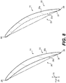
- FIG. 8 is a cross-sectional view through two adjacent airfoils 112, 114, taken along an arc length (in the tangential direction or along the T-axis) of the rotor 102 starting from line 7-7 of FIG. 4 into the page. As shown in FIG.
- the different pressure side surface 224a, 240a shapes in the first operating state of the rotor 102 result in the airfoils 112, 114 having different suction side surface 226a, 242a shapes between about 0% span and about 50% span and between about 10% and about 90% of the chord CH in the static state of the rotor 102 as the hot to cold deflections are different for each of the airfoils 112, 114.
- the different pressure side surface 224a shape (caused by the reduced thickness) between about 0% span and about 50% span and between about 10% to about 90% chord CH is illustrated with a dashed line in FIG. 8 .
- the airfoils 112 are manufactured based on the static shape for the airfoil 112, which is determined based on the first working shape and the second working shape; and the airfoils 114 are manufactured based on the static shape for the airfoil 114, which is determined based on the first working shape and the third working shape.
- FIG. 9 is a cross-sectional view through two adjacent airfoils 112, 114, taken along an arc length (in the tangential direction or along the T-axis) of the rotor 102 starting from line 6-6 of FIG. 4 into the page.
- the different pressure side surface 224a, 240a shapes result in the airfoils 112, 114 having different suction side surface 226a, 242a shapes between about 80% span and about 100% span and between about 10% and about 90% of the chord CH in the static operating state of the rotor 102.
- FIG. 10 is a cross-sectional view in which a cross-section 250 of the airfoil 112 at 20% span in the first operating state is overlaid onto a cross-section 252 of the airfoil 112 at 20% span in the static state.
- the airfoil 112 has a static shape in the static state that is different than the second working shape of the airfoil 112 in the first operating state of the rotor 102.
- the deflection of the airfoil 112 in the first operating state is constrained by the attachment of the airfoil 112 at 0% span to the rotor disk 200.
- FIG. 11 FIG. 11
- FIG. 11 is a cross-sectional view in which a cross-section 254 of the airfoil 112 at 80% span in the first operating state is overlaid onto a cross-section 256 of the airfoil 112 at 80% span in the static state.
- the airfoil 112 has a static shape in the static state that is different than the first working shape of the airfoil 112 in the first operating state of the rotor 102.
- FIG. 12 is a cross-sectional view in which a cross-section 260 of the airfoil 114 at 20% span in the first operating state is overlaid onto a cross-section 262 of the airfoil 114 at 20% span in the static state.
- the airfoil 114 has a static shape in the static state that is different than the second working shape of the airfoil 114 in the first operating state of the rotor 102.
- the cross-sections are at 20% span, the deflection of the airfoil 114 in the first operating state is constrained by the attachment of the airfoil 114 at 0% span to the rotor disk 200.
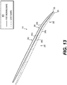
- FIG. 13 FIG.
- FIG. 13 is a cross-sectional view in which a cross-section 264 of the airfoil 114 at 80% span in the first operating state is overlaid onto a cross-section 266 of the airfoil 114 at 80% span in the static state.
- the airfoil 114 has a static shape in the static state that is different than the first working shape of the airfoil 114 in the first operating state of the rotor 102.
- the rotor 102 With the rotor 102 formed with the airfoils 112, 114 arranged in an alternating pattern about the circumference of the rotor disk 200, the rotor 102 is installed in the gas turbine engine 104 ( FIG. 2 ).
- the rotor 102 may be incorporated into one or more of the engine sections described with regard to FIG. 2 above.
- the rotor 102 may be incorporated into the fan section 120 such that, as the rotor 102 rotates, the airfoils 112, 114 function to draw air into the gas turbine engine 104 with reduced susceptibility to flutter.
- the rotor 102 may be incorporated into the compressor section 122 such that, as the rotor 102 rotates, the airfoils 112, 114 function to compress the air flowing through the airfoils 112, 114 with reduced susceptibility to flutter.
- the rotor manufacturing system 100 is used to manufacture or machine the airfoils 112, 114.
- the manufacturing system 106 is any system or device that is capable of creating, manufacturing or machining the airfoils 112, 114 of the rotor 102.
- the manufacturing system 106 manufacture or machines the airfoils 112, 114 based on one or more instructions received from the controller 110. It should be noted that the manufacturing system 106 machines both the pressure side surface and the opposite suction side surface associated with each of the airfoils 112, 114 such that upon completion of the machining the airfoil 112, 114 is formed for use in the rotor 102.
- the manufacturing system 106 includes, but is not limited to, a computer numeric control (CNC) machine, a three dimensional metal printing machine, a direct metal laser sintering machine, an electro-chemical machining machine, a powder metallurgy machine, a composite ply lay-up machine or other composite manufacturing machines to list but a few examples.
- the manufacturing system 106 generally machines each of the airfoils 112, 114 of a respective rotor disk out of a metal, metal alloy or polymer-based material, such as a composite.
- the manufacturing system 106 includes a manufacturing controller 270, which is in communication with the controller 110 via a suitable communication architecture, such as a bus.
- the manufacturing controller 270 includes at least one manufacturing processor 272 and a manufacturing computer readable storage device or media 274.
- the manufacturing processor 272 can be any custom made or commercially available processor, a central processing unit (CPU), a graphics processing unit (GPU), an auxiliary processor among several processors associated with the manufacturing controller 270, a semiconductor based microprocessor (in the form of a microchip or chip set), a macroprocessor, any combination thereof, or generally any device for executing instructions.
- the manufacturing computer readable storage device or media 274 may include volatile and nonvolatile storage in read-only memory (ROM), random-access memory (RAM), and keep-alive memory (KAM), for example.
- KAM is a persistent or non-volatile memory that may be used to store various operating variables while the manufacturing processor 272 is powered down.
- the computer-readable storage device or media 274 may be implemented using any of a number of known memory devices such as PROMs (programmable read-only memory), EPROMs (electrically PROM), EEPROMs (electrically erasable PROM), flash memory, or any other electric, magnetic, optical, or combination memory devices capable of storing data, some of which represent executable instructions, used by the manufacturing controller 270 in controlling components associated with the manufacturing system 106.
- the instructions may include one or more separate programs, each of which comprises an ordered listing of executable instructions for implementing logical functions.
- the instructions when executed by the manufacturing processor 272, receive and process input signals, perform logic, calculations, methods and/or algorithms for controlling the components of the manufacturing system 106, and generate control signals to the components of the manufacturing system 106, including, but not limited to, a cutting tool associated with the manufacturing system 106 to form or machine the airfoils 112, 114 based on the logic, calculations, methods, and/or algorithms.
- a cutting tool associated with the manufacturing system 106 to form or machine the airfoils 112, 114 based on the logic, calculations, methods, and/or algorithms.
- embodiments of the manufacturing system 106 can include any number of manufacturing controllers 270 that communicate over any suitable communication medium or a combination of communication mediums and that cooperate to process the sensor signals, perform logic, calculations, methods, and/or algorithms, and generate control signals to control features of the manufacturing system 106.
- the manufacturing controller 270 executes the instructions to machine the airfoils 112, 114 based on data received from the controller 110.
- the human-machine interface 108 is in communication with the controller 110 via a suitable communication medium, such as a bus.
- the human-machine interface 108 may be configured in a variety of ways.
- the human-machine interface 108 may include various switches, one or more buttons, a touchscreen interface 278 that may be overlaid on a display 280, a keyboard, an audible device, a microphone associated with a speech recognition system, or various other human-machine interface devices.
- the touchscreen interface 278 may receive input from the user, such as operating criteria data for the rotor 102.
- the touchscreen interface 278 may include, but is not limited to, a resistive touchscreen panel, a capacitive touchscreen panel, a projected capacitance touchscreen panel, a surface capacitive touchscreen panel, a surface acoustic wave touchscreen panel, etc.
- the human-machine interface 108 transmits a signal to the controller 110.
- the controller 110 processes the signal, and determines the operating criteria data based on the user's interaction with the human-machine interface 108.
- the display 280 comprises any suitable technology for displaying information, including, but not limited to, a liquid crystal display (LCD), organic light emitting diode (OLED), plasma, or a cathode ray tube (CRT).
- the display 280 is an electronic display capable of graphically displaying one or more user interfaces under the control of the controller 110.
- Those skilled in the art may realize other techniques to implement the display 280 in the rotor manufacturing system 100.
- the human-machine interface 108 and the controller 110 may be associated with a personal computing device, including, but not limited to a desktop computer, laptop computer, tablet, portable electronic device, etc.
- the manufacturing system 106 may include the controller 110 such that in certain embodiments, the rotor manufacturing system 100 may include the manufacturing system 106 having the controller 110 and the manufacturing controller 270.
- the controller 110 includes at least one processor 282 and a computer readable storage device or media 284.
- the processor 282 can be any custom made or commercially available processor, a central processing unit (CPU), a graphics processing unit (GPU), an auxiliary processor among several processors associated with the controller 110, a semiconductor based microprocessor (in the form of a microchip or chip set), a macroprocessor, any combination thereof, or generally any device for executing instructions.
- the computer readable storage device or media 284 may include volatile and nonvolatile storage in read-only memory (ROM), random-access memory (RAM), and keep-alive memory (KAM), for example.
- KAM is a persistent or non-volatile memory that may be used to store various operating variables while the processor 282 is powered down.
- the computer-readable storage device or media 284 may be implemented using any of a number of known memory devices such as PROMs (programmable read-only memory), EPROMs (electrically PROM), EEPROMs (electrically erasable PROM), flash memory, or any other electric, magnetic, optical, or combination memory devices capable of storing data, some of which represent executable instructions, used by the controller 110 in controlling components associated with the rotor manufacturing system 100.
- PROMs programmable read-only memory
- EPROMs electrically PROM
- EEPROMs electrically erasable PROM
- flash memory or any other electric, magnetic, optical, or combination memory devices capable of storing data, some of which represent executable instructions, used by the controller 110 in controlling components associated with the rotor manufacturing system 100.
- the instructions may include one or more separate programs, each of which comprises an ordered listing of executable instructions for implementing logical functions.
- the instructions when executed by the processor 282, receive and process input signals, perform logic, calculations, methods and/or algorithms for controlling the components of the rotor manufacturing system 100, and generate control signals to components of the rotor manufacturing system 100 to manufacture the airfoils 112, 114 based on the logic, calculations, methods, and/or algorithms.
- controller 110 is shown in FIG. 1
- embodiments of the rotor manufacturing system 100 can include any number of controllers 110 that communicate over any suitable communication medium or a combination of communication mediums and that cooperate to process the sensor signals, perform logic, calculations, methods, and/or algorithms, and generate control signals to control features of the rotor manufacturing system 100.
- one or more instructions of the controller 110 are associated with the rotor manufacturing system 100 and, when executed by the processor 282, the instructions receive and process signals from the human-machine interface 108 and receive input data regarding the operating criteria for the rotor 102.
- the instructions of the controller 110 when executed by the processor 282, determine whether to intentionally mistune the airfoils 112, 114 associated with the rotor 102, determines the working shapes of the airfoils 112, 114 and outputs static shape instruction data to the manufacturing controller 270 to manufacture the airfoils 112, 114 based on these determinations.
- the instructions of the controller 110 when executed by the processor 282, also outputs a user interface for display on the display 280 based on the determined static shape for the airfoils 112, 114.
- a dataflow diagram illustrates various embodiments of an airfoil manufacturing system 300 of the rotor manufacturing system 100, which may be embedded within the controller 110.
- Various embodiments of the airfoil manufacturing system 300 according to the present disclosure can include any number of sub-modules embedded within the controller 110.
- the sub-modules shown in FIG. 14 may be combined and/or further partitioned to similarly receive data from the human-machine interface 108, and output data and one or more user interfaces. Inputs to the airfoil manufacturing system 300 may be received from the human-machine interface 108 ( FIG.
- the airfoil manufacturing system 300 includes a user interface (UI) control module 302, a shape determination module 306, a datastore 308, a mistune determination module 312 and a hot to cold transformation module 314.
- UI user interface
- the UI control module 302 receives input data 316.
- the input data 316 is received from the human-machine interface 108 via the user's interaction with the human-machine interface 108, for example, the user's interaction with the touchscreen interface 278.
- the UI control module 302 processes the input data 316, and based on the input data 316, the UI control module 302 sets operating criteria data 318 for the shape determination module 306.
- the operating criteria data 318 is one or more defined or known operating characteristics for the rotor 102 that are entered as input by the user via the human-machine interface 108.
- the UI control module 302 also processes the input data 316, and based on the input data 316, the UI control module 302 sets mistune 319 or same shape 321 for the mistune determination module 312.
- the mistune 319 is a command to manufacture the airfoils 112, 114 associated with the rotor 102 such that one or more of the airfoils 112, 114 has a different shape and a different natural vibratory frequency.
- the same shape 321 is a command to manufacture the airfoils 112, 114 associated with the rotor 102 such that the airfoils 112, 114 have the same shape.
- the UI control module 302 also receives as input static shapes data 320 from the hot to cold transformation module 314.
- the static shapes data 320 is data that indicates the static shapes for the airfoils 112, 114 in the second operating condition of the rotor 102.
- the UI control module 302 Based on the static shapes data 320, the UI control module 302 generates and outputs manufacturing instruction user interface data 322 for rendering a user interface including the static shapes data 320 on the display 280.
- the manufacturing instruction user interface data 322 comprises data for rendering the user interface including the static shapes data 320 in a graphical format, such as a three-dimensional image, on the display 280.
- the manufacturing instruction user interface data 322 may also comprise data for rendering the user interface including the static shapes data 320 in a graphical format, such as part drawing, on the display 280.
- the user interface rendered based on the manufacturing instruction user interface data 322 is displayed on the display 280 by the controller 110 to inform the user of the static shapes data 320 for the airfoils 112, 114.
- the UI control module 302 also receives as input flutter risk data 323 from the mistune determination module 312.
- the flutter risk data 323 is data that indicates a risk of flutter associated with the airfoils 112, 114 in the first operating condition of the rotor 102.
- the UI control module 302 Based on the flutter risk data 323, the UI control module 302 generates and outputs flutter risk user interface data 324 for rendering a user interface including the flutter risk data 323 on the display 280.
- the flutter risk user interface data 324 comprises data for rendering the user interface including the flutter risk data 323 in a graphical format, such as a graph of a flutter boundary, on the display 280.
- the flutter risk user interface data 324 may also comprise data for rendering the user interface including the flutter risk data 323 in a textual format or tabular format on the display 280.
- the user interface rendered based on the flutter risk user interface data 324 is displayed on the display 280 by the controller 110 to inform the user of flutter risk for the airfoils 112, 114.
- the shape determination module 306 receives as input the operating criteria data 318 from the UI control module 302.
- the shapes determination module 306 performs a series of physics-based assessments based on the operating criteria data 318 to determine a baseline working shape or baseline shape data 326 for each of the airfoils 112, 114 in the first operating state of the rotor 102.
- the physics-based assessments may include computational fluid analysis, etc. as known to one skilled in the art to determine the baseline shape data 326.
- the baseline shape data 326 is the baseline working shape geometry for the airfoils 112, 114 of the rotor 102, which is determined based on the operating criteria of the rotor 102.
- the shapes determination module 306 sets the baseline shape data 326 for each of the airfoils 112, 114 for the mistune determination module 312.
- the datastore 308 stores data of a natural vibratory frequency difference range between the airfoils 112, 114.
- the datastore 308 stores a frequency difference range 328, which is a known, predefined or factory-set range for a frequency difference between directly adjacent ones of the airfoils 112, 114.
- the frequency difference range 328 is about 3% to about 15%.
- the mistune determination module 312 receives as input the baseline shape data 326. Based on the baseline shape data 326, the mistune determination module 312 determines the flutter boundary for the rotor 102. In one example, the mistune determination module 312 determines the flutter boundary in the first operating state of the rotor 102 based on high fidelity unsteady aero-elastic analysis of the operation of the rotor 102 in the first operating state and the natural vibratory frequency of the airfoils 112, 114 with the same baseline shape geometry. The predicted flutter boundary is the flutter risk associated with the airfoils 112, 114 of the rotor 102 in the first operating condition of the rotor 102. The mistune determination module 312 sets the determined flutter boundary as the flutter risk data 323 for the UI control module 302.
- the mistune determination module 312 receives as input the mistune 319 from the UI control module 302. Based on the mistune 319, for each airfoil 112, 114 of the rotor 102, the mistune determination module 312 determines a first working shape for each of the airfoils 112, 114 in the first operating state of the rotor 102.
- the first working shape is based on the baseline shape data 326, and may comprise the baseline shape data 326 which is unmodified.
- the first working shape for each of the airfoils 112, 114 is the same suction side surface shape and the same pressure side surface shape between 10% and 90% of the chord and between 80% and 100% of the span.
- the mistune determination module 312 determines a second working shape for the airfoil 112, which is different than a third working shape for the airfoil 114.
- the second working shape modifies the baseline shape data 326 to reduce a thickness of the airfoil 112 between 0% and 50% of the span, which results in a corresponding shape change in the pressure side surface 224a ( FIG. 7 ).
- the mistune determination module 312 determines to modify the baseline shape data 326 to reduce the maximum thickness of the airfoil 112 by modifying the pressure side surface 224a ( FIG. 7 ) by about 10% to about 30% to change the natural vibratory frequency of the airfoil 112.
- the third working shape is based on the baseline shape data 326, and may comprise the baseline shape data 326 which is unmodified.
- the mistune determination module 312 determines, based on the first working shape and the second working shape, a natural vibratory frequency for the airfoils 112. The mistune determination module 312 determines, based on the first working shape and the third working shape, the natural vibratory frequency for the airfoils 114. In one example, the mistune determination module 312 determines the natural vibratory frequency of the airfoils 112, 114 using computational fluid dynamics analysis. The mistune determination module 312 determines the frequency difference between adjacent ones of the airfoils 112, 114 based on the determined natural vibratory frequencies. The mistune determination module 312 queries the datastore 308 and retrieves the frequency difference range 328.
- the mistune determination module 312 compares the frequency difference between adjacent ones of the airfoils 112, 114 to the frequency difference range 328. Based on the comparison, if the frequency difference between adjacent ones of the airfoils 112, 114 is within the range provided by the frequency difference range 328, the mistune determination module 312 processes the first working shape, the second working shape and the remainder of the baseline shape geometry of the airfoil 112 (from the baseline shape data 326) to ensure the baseline shape geometry of the airfoil 112 meets other design criteria for the rotor 102 and the airfoil 112, including, but not limited to, a flow capacity of the rotor 102, a pressure rise of the rotor 102, geometric constraints including length and diameter of the rotor 102, a flutter and stability margin for the rotor 102, and durability requirements for the rotor 102 and the airfoil 112, including foreign object debris tolerance.
- the mistune determination module 312 uses computational fluid dynamics analysis to process the geometry of the airfoil 112 for compliance with the other requirements. Once complete, the mistune determination module 312 sets the first working shape, the second working shape and the remainder of the baseline shape geometry of the airfoil 112 (from the baseline shape data 326), as modified for the other design requirements, as applicable, as first airfoil shape data 334 for the hot to cold transformation module 314.
- the first airfoil shape data 334 is complete shape geometry for the airfoil 112 (pressure and suction side surfaces) in the first operating state of the rotor 102, which includes the thickness modifications between about 0% to 50% span and about 10% to about 90% of the chord of the airfoil 112 on the pressure side surface 224a ( FIG. 7 ) to result in a different natural vibratory frequency for the airfoil 112.
- the mistune determination module 312 processes the first working shape, the third working shape and the remainder of the baseline shape geometry of the airfoil 114 (from the baseline shape data 326) to ensure the baseline shape geometry of the airfoil 114 meets other design criteria for the rotor 102 and the airfoil 114, including, but not limited to, a flow capacity of the rotor 102, a pressure rise of the rotor 102, geometric constraints including length and diameter of the rotor 102, a flutter and stability margin for the rotor 102, and durability requirements for the rotor 102 and the airfoil 114, including foreign object debris tolerance.
- the mistune determination module 312 uses computational fluid dynamics analysis to process the geometry of the airfoil 114 for compliance with the other requirements. Once complete, the mistune determination module 312 sets the first working shape, the third working shape and the remainder of the baseline shape geometry of the airfoil 114 (from the baseline shape data 326), as modified for the other design requirements, as applicable, as second airfoil shape data 336 for the hot to cold transformation module 314.
- the second airfoil shape data 336 is complete shape geometry for the airfoil 114 (pressure and suction side surfaces) in the first operating state of the rotor 102.
- the mistune determination module 312 Based on the comparison, if the frequency difference between adjacent ones of the airfoils 112, 114 is outside of the range provided by the frequency difference range 328, the mistune determination module 312 repeats the process of determining a second working shape for the airfoil 112, the determining of the natural vibratory frequency for the airfoils 112, 114 and the comparison to arrive at a second working shape that creates a natural vibratory frequency difference that is within the frequency difference range 328.
- the mistune determination module 312 may set an error message for the UI control module 302, and the UI control module 302 may output error user interface data for rendering an error user interface on the display 280 ( FIG. 1 ), which indicates an error in determining the second working shape for the airfoils 112.
- the mistune determination module 312 receives as input the same shape 321 from the UI control module 302. Based on the same shape 321, for each airfoil 112, 114 of the rotor 102, the mistune determination module 312 processes the baseline shape data 326 to ensure the baseline shape geometry of the airfoils 112, 114 meets other design criteria for the rotor 102 and the airfoils 112, 114, including, but not limited to, a flow capacity of the rotor 102, a pressure rise of the rotor 102, geometric constraints including length and diameter of the rotor 102, a flutter and stability margin for the rotor 102, and durability requirements for the rotor 102 and the airfoils 112, 114, including foreign object debris tolerance.
- the hot to cold transformation module 314 receives as input the shape data 332, which provides the same shape for the airfoils 112, 114 in the first operating state of the rotor 102. Based on the shape data 332, performs a hot to cold geometry transformation to generate static shapes for the airfoils 112, 114 in the second operating condition of the rotor 102. In one example, the hot to cold transformation module 314 performs the hot to cold geometry transformation with a finite element solver that assesses the impact of rotational speed, thermal changes, pressure load changes and contact force changes to determine the static shape for the airfoils 112, 114. The hot to cold transformation module 314 sets the generated static shapes for the airfoils 112, 114 as the static shapes data 320.
- the method processes the baseline shape data 326 for compliance with the other requirements, using computational fluid dynamics analysis, for example.
- the method sets shape data 332, as modified for the other design requirements, as applicable, which provides the same shape for the airfoils 112, 114.
- the method performs the hot to cold geometry transformation based on the shape data 332 to generate the static shapes for the airfoils 112, 114 in the second operating condition of the rotor 102.
- the method generates manufacturing instruction user interface data 322 for rendering a user interface on the display 280 based on the generated static shapes.
- the method processes the first working shape, the second working shape and the remainder of the baseline shape geometry of the airfoil 112 (from the baseline shape data 326) to ensure the baseline shape geometry of the airfoil 112 meets other design criteria for the rotor 102 and the airfoil 112, including, but not limited to, a flow capacity of the rotor 102, a pressure rise of the rotor 102, geometric constraints including length and diameter of the rotor 102, a flutter and stability margin for the rotor 102, and durability requirements for the rotor 102 and the airfoil 112, including foreign object debris tolerance.
- the method sets the first working shape, the second working shape and the remainder of the baseline shape geometry of the airfoil 112 (from the baseline shape data 326), as modified for the other design requirements, as applicable, as the first airfoil shape data 334.
- the method performs the hot to cold geometry transformation based on the first airfoil shape data 334 to generate the static shapes for the airfoils 112 in the second operating condition of the rotor 102.
- the method performs the hot to cold geometry transformation based on the second airfoil shape data 336 to generate the static shapes for the airfoils 114 in the second operating condition of the rotor 102.
- the method proceeds to 418.
Landscapes
- Engineering & Computer Science (AREA)
- Mechanical Engineering (AREA)
- General Engineering & Computer Science (AREA)
- Physics & Mathematics (AREA)
- Fluid Mechanics (AREA)
- Structures Of Non-Positive Displacement Pumps (AREA)
- Turbine Rotor Nozzle Sealing (AREA)
Abstract
Description
- The present disclosure generally relates to gas turbine engines, and more particularly relates to mistuned rotors and methods for manufacture of a mistuned rotor for a gas turbine engine.
- Gas turbine engines may be employed to power various devices. For example, a gas turbine engine may be employed to power a mobile platform, such as an aircraft. Generally, gas turbine engines include one or more fans or compressors, which operate to draw air into the gas turbine engine and to raise a pressure of that air. Each of the fans and compressors has one or more airfoils coupled to a rotor that is rotatable to accomplish this task. During the operation of the fans and compressors, due to a natural vibratory frequency of the airfoils, the fans and compressors may experience aerodynamic instability, or flutter. Flutter of the airfoils is generally detrimental to the operation of the fan or compressor, and is generally detrimental to the operation of the gas turbine engine.
- Accordingly, it is desirable to provide a mistuned rotor for a fan or compressor and methods for manufacture of the mistuned rotor, in which the one or more airfoils of the rotor are mistuned to reduce susceptibility to flutter. Furthermore, other desirable features and characteristics of the present invention will become apparent from the subsequent detailed description and the appended claims, taken in conjunction with the accompanying drawings and the foregoing technical field and background.
- According to various embodiments, provided is a rotor for a gas turbine engine. The rotor includes a plurality of airfoils each extending from a root to a tip and having a leading edge opposite a trailing edge. Each airfoil of the plurality of airfoils has a span that extends from 0% at the root to 100% at the tip, a chord that extends from 0% at the leading edge to 100% at the trailing edge and a pressure side opposite a suction side. The pressure side of each airfoil of the plurality of airfoils has a pressure side surface shape based on an operating state of the rotor and the suction side of each airfoil of the plurality of airfoils has a suction side surface shape based on the operating state of the rotor. Each airfoil of the plurality of airfoils has the same suction side surface shape between 10% and 90% of the chord and between 80% and 100% of the span at a first operating state of the rotor. At least one first airfoil of the plurality of airfoils has a different suction side surface shape between 10% and 90% of the chord and between 80% and 100% of the span than at least one second airfoil of the plurality of airfoils at a static state of the rotor.
- Also provided according to various embodiments is a method for manufacturing a rotor for a gas turbine engine. The rotor includes a plurality of airfoils. The method includes determining, by a processor, a first working shape for a suction side surface of each airfoil of the plurality of airfoils at a first operating state of the rotor. Each airfoil of the plurality of airfoils includes a suction side having the suction side surface opposite a pressure side having a pressure side surface, a leading edge opposite a trailing edge and extending from a root to a tip. Each airfoil of the plurality of airfoils has a span that extends from 0% at the root to 100% at the tip and a chord that extends from 0% at the leading edge to 100% at the trailing edge. The first working shape for the suction side surface is the same for each airfoil of the plurality of airfoils between 10% and 90% of the chord and 80% and 100% of the span. The method includes determining, by the processor, a second working shape for at least one of the suction side surface and the pressure side surface of at least one first airfoil of the plurality of airfoils between 0% and 50% of the span that is different than a third working shape for at least one of the suction side surface and the pressure side surface of at least one second airfoil of the plurality of airfoils between 0% and 50% of the span at the first operating state of the rotor. The method includes determining, by the processor, a static shape for each airfoil of the plurality of airfoils at a static state of the rotor. The static shape is based on at least one of the first working shape, the second working shape and the third working shape. The method includes generating, by the processor, a user interface for rendering on a display that includes instructions to manufacture each airfoil of the plurality of airfoils based on the static shape.
- Also provided is a rotor for a gas turbine engine. The rotor includes a plurality of airfoils each extending from a root to a tip and having a leading edge opposite a trailing edge. Each airfoil of the plurality of airfoils has a span that extends from 0% at the root to 100% at the tip, and a pressure side opposite a suction side. The pressure side of each airfoil of the plurality of airfoils has a pressure side surface shape based on an operating state of the rotor and the suction side of each airfoil of the plurality of airfoils has a suction side surface shape based on the operating state of the rotor. Each airfoil of the plurality of airfoils has the same suction side surface shape and the same pressure side surface shape between 80% and 100% of the span at a first operating state of the rotor. At least one first airfoil of the plurality of airfoils has the pressure side surface shape between 0% and 50% of the span that is different than the pressure side surface shape between 0% and 50% of the span of at least one second airfoil of the plurality of airfoils at the first operating state of the rotor. The at least one first airfoil of the plurality of airfoils has a different suction side surface shape between 80% and 100% of the span than the at least one second airfoil of the plurality of airfoils at a static state of the rotor.
- The exemplary embodiments will hereinafter be described in conjunction with the following drawing figures, wherein like numerals denote like elements, and wherein:
-
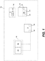
FIG. 1 is a functional block diagram illustrating a rotor manufacturing system for a mistuned rotor for use with a gas turbine engine in accordance with the various teachings of the present disclosure; -
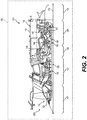
FIG. 2 is a schematic cross-sectional illustration of the gas turbine engine, which includes the mistuned rotor manufactured by the rotor manufacturing system ofFIG. 1 in accordance with the various teachings of the present disclosure; -
FIG. 3 is a front view of the mistuned rotor manufactured by the rotor manufacturing system ofFIG. 1 , in which the mistuned rotor includes a plurality of first airfoils that alternate with a plurality of second airfoils; -
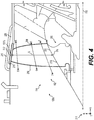
FIG. 4 is a detail cross-sectional view of the mistuned rotor manufactured by the rotor manufacturing system ofFIG. 1 for use in a fan section of the gas turbine engine, which illustrates one of the first airfoils of the mistuned rotor according to various embodiments; -
FIG. 4A is a detail cross-sectional view of the mistuned rotor manufactured by the rotor manufacturing system ofFIG. 1 for use in a fan section of the gas turbine engine, which illustrates one of the second airfoils of the mistuned rotor according to various embodiments; -
FIG. 5 is a cross-sectional view of the first airfoil ofFIG. 4 , taken along line 5-5 ofFIG. 4 ; -
FIG. 5A is a cross-sectional view of the second airfoil ofFIG. 4A , taken alongline 5A-5A ofFIG. 4A ; -
FIG. 6 is a cross-sectional view of one of the first airfoils that is directly adjacent to one of the second airfoils of the mistuned rotor ofFIG. 3 , taken along an arc length (tangential direction) of the rotor starting from line 6-6 ofFIG. 4 , which illustrates that a first working shape for the first airfoils and the second airfoils in a first operating state of the mistuned rotor is the same between about 80% span and about 100% span, and between about 10% and about 90% chord; -
FIG. 7 is a cross-sectional view of one of the first airfoils that is directly adjacent to one of the second airfoils of the mistuned rotor ofFIG. 3 , taken along an arc length (tangential direction) of the rotor starting from line 7-7 ofFIG. 4 , which illustrates that a second working shape for the first airfoils is different than a third working shape for the second airfoils in the first operating state of the mistuned rotor between about 0% span and about 50% span, and between about 10% and about 90% chord; -
FIG. 8 is a cross-sectional view of one of the first airfoils that is directly adjacent to one of the second airfoils of the mistuned rotor ofFIG. 3 , taken along an arc length (tangential direction) of the rotor starting from line 7-7 ofFIG. 4 , which illustrates that a static shape for the first airfoils is different than a static shape for the second airfoils in a second operating state of the mistuned rotor between about 0% span and about 50% span; -
FIG. 9 is a cross-sectional view of one of the first airfoils that is directly adjacent to one of the second airfoils of the mistuned rotor ofFIG. 3 , taken along an arc length (tangential direction) of the rotor starting from line 6-6 ofFIG. 4 , which illustrates that a static shape for the first airfoils is different than a static shape for the second airfoils in the second operating state of the mistuned rotor between about 80% span and about 100% span; -
FIG. 10 is an overlay of a cross-section of the second working shape of the first airfoil in the first operating state of the mistuned rotor and a cross-section of the static shape of the first airfoil in the second operating state of the mistuned rotor between about 0% span and about 50% span taken from the perspective of line 7-7 ofFIG. 4 ; -
FIG. 11 is an overlay of a cross-section of the first working shape of the first airfoil in the first operating state of the mistuned rotor and a cross-section of the static shape of the first airfoil in the second operating state of the mistuned rotor between about 80% span and about 100% span taken from the perspective of line 6-6 ofFIG. 4 ; -
FIG. 12 is an overlay of a cross-section of the third working shape of the second airfoil in the first operating state of the mistuned rotor and a cross-section of the static shape of the second airfoil in the second operating state of the mistuned rotor between about 0% span and about 50% span taken from the perspective of line 7-7 ofFIG. 4 ; -
FIG. 13 is an overlay of a cross-section of the first working shape of the second airfoil in the first operating state of the mistuned rotor and a cross-section of the static shape of the second airfoil in the second operating state of the mistuned rotor between about 80% span and about 100% span taken from the perspective of line 6-6 ofFIG. 4 ; -
FIG. 14 is a dataflow diagram illustrating an airfoil manufacturing system of the rotor manufacturing system ofFIG. 1 , in accordance with various embodiments; -
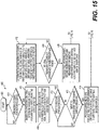
FIG. 15 is a flowchart illustrating a control method for the airfoil manufacturing system of the rotor manufacturing system ofFIG. 1 , in accordance with various embodiments; and -
FIG. 16 is a continuation of the flowchart ofFIG. 15 . - The following detailed description is merely exemplary in nature and is not intended to limit the application and uses. Furthermore, there is no intention to be bound by any expressed or implied theory presented in the preceding technical field, background, brief summary or the following detailed description. In addition, those skilled in the art will appreciate that embodiments of the present disclosure may be practiced in conjunction with any type of rotor, and the rotor for a fan or compressor of a gas turbine engine is merely one exemplary embodiment according to the present disclosure. In addition, while the rotor is described herein as being employed with a gas turbine engine onboard a mobile platform, such as a bus, motorcycle, train, motor vehicle, marine vessel, aircraft, rotorcraft and the like, the various teachings of the present disclosure can be used with a gas turbine engine on a stationary platform. Further, it should be noted that many alternative or additional functional relationships or physical connections may be present in an embodiment of the present disclosure. In addition, while the figures shown herein depict an example with certain arrangements of elements, additional intervening elements, devices, features, or components may be present in an actual embodiment. It should also be understood that the drawings are merely illustrative and may not be drawn to scale.
- As used herein, the term "axial" refers to a direction that is generally parallel to or coincident with an axis of rotation, axis of symmetry, or centerline of a component or components. For example, in a cylinder or disc with a centerline and generally circular ends or opposing faces, the "axial" direction may refer to the direction that generally extends in parallel to the centerline between the opposite ends or faces. In certain instances, the term "axial" may be utilized with respect to components that are not cylindrical (or otherwise radially symmetric). For example, the "axial" direction for a rectangular housing containing a rotating shaft may be viewed as a direction that is generally parallel to or coincident with the rotational axis of the shaft. Furthermore, the term "radially" as used herein may refer to a direction or a relationship of components with respect to a line extending outward from a shared centerline, axis, or similar reference, for example in a plane of a cylinder or disc that is perpendicular to the centerline or axis. In certain instances, components may be viewed as "radially" aligned even though one or both of the components may not be cylindrical (or otherwise radially symmetric). Furthermore, the terms "axial" and "radial" (and any derivatives) may encompass directional relationships that are other than precisely aligned with (e.g., oblique to) the true axial and radial dimensions, provided the relationship is predominately in the respective nominal axial or radial direction. As used herein, the term "transverse" denotes an axis that crosses another axis at an angle such that the axis and the other axis are neither substantially perpendicular nor substantially parallel.
- As used herein, the term module refers to any hardware, software, firmware, electronic control component, processing logic, and/or processor device, individually or in any combination, including without limitation: application specific integrated circuit (ASIC), an electronic circuit, a processor (shared, dedicated, or group) and memory that executes one or more software or firmware programs, a combinational logic circuit, and/or other suitable components that provide the described functionality.
- Embodiments of the present disclosure may be described herein in terms of schematic, functional and/or logical block components and various processing steps. It should be appreciated that such block components may be realized by any number of hardware, software, and/or firmware components configured to perform the specified functions. For example, an embodiment of the present disclosure may employ various integrated circuit components, e.g., memory elements, digital signal processing elements, logic elements, look-up tables, or the like, which may carry out a variety of functions under the control of one or more microprocessors or other control devices. In addition, those skilled in the art will appreciate that embodiments of the present disclosure may be practiced in conjunction with any number of systems, and that the manufacturing system described herein is merely exemplary embodiments of the present disclosure.
- For the sake of brevity, conventional techniques related to signal processing, data transmission, signaling, control, and other functional aspects of the systems (and the individual operating components of the systems) may not be described in detail herein. Furthermore, the connecting lines shown in the various figures contained herein are intended to represent example functional relationships and/or physical couplings between the various elements. It should be noted that many alternative or additional functional relationships or physical connections may be present in an embodiment of the present disclosure.
-
FIG. 1 is a functional block diagram of arotor manufacturing system 100 for arotor 102 for agas turbine engine 104 according to various embodiments. In one example, therotor manufacturing system 100 includes amanufacturing system 106, a human-machine interface 108 and acontroller 110. As will be discussed, therotor manufacturing system 100 manufactures andmachines airfoils rotor 102 to provide an intentional mistuning of theairfoils rotor 102, and thus, a mistuned rotor. The intentional mistuning of therotor 102 reduces a susceptibility of theairfoils rotor 102. In this regard, as theairfoils airfoils rotor 102, the natural vibratory frequencies of theairfoils airfoils rotor 102, which reduces aerodynamic variations between the tips ofadjacent airfoils airfoils 112 have a second working shape between about 0% and about 50% of the span in the first operating state of therotor 102. Theadjacent airfoils 114, however, have a third working shape between about 0% and about 50% of the span in the first operating state of therotor 102, which is different than the second working shape. The difference between the second working shape and the third working shape results in a difference between the natural vibratory frequencies of theairfoils airfoils rotor 102, which is determined based on the first working shape, the second working shape and the third working shape, and theairfoils rotor 102 is a hot or rotating state of therotor 102, or an operating state in which therotor 102 is moving or rotating at a speed greater than about 900 feet per second (ft/s). The second operating state of therotor 102 is an operating state in which therotor 102 is static, stationary or unmoving. It should be noted that while the description herein refers to therotor 102 having twoairfoils rotor 102 may have any number of airfoils each with different natural frequencies if desired. - Initially, with reference to
FIG. 2 , a partial, cross-sectional view of thegas turbine engine 104 is shown with the remaining portion of thegas turbine engine 104 being substantially axisymmetric about alongitudinal axis 115, which also comprises an axis of rotation for thegas turbine engine 104. In the depicted embodiment, thegas turbine engine 104 is an annular multi-spool turbofan gas turbine jet engine within anaircraft 116, although other arrangements and uses may be provided. Thegas turbine engine 104 includes therotor 102, which includes theairfoils FIG. 14 ) of therotor manufacturing system 100, which will be discussed with regard toFIGS. 14-16 . The airfoil manufacturing system 300 ensures that theairfoils rotor 102 are manufactured by the manufacturing system 106 (FIG. 1 ) to reduce susceptibility to flutter, while also reducing acoustic energy. Thus, the airfoil manufacturing system 300 generates themistuned rotor 102 for use with thegas turbine engine 104. - In this example, with continued reference to
FIG. 2 , thegas turbine engine 104 includes afan section 120, thecompressor section 122, acombustor section 124, aturbine section 126, and anexhaust section 128. In one example, thefan section 120 includes afan 120a. Thefan 120a includes theairfoils rotor 102 that draws air into thegas turbine engine 104 and accelerates it. A fraction of the accelerated air exhausted from thefan section 120 is directed through anouter bypass duct 130 and the remaining fraction of air exhausted from thefan section 120 is directed into thecompressor section 122. Theouter bypass duct 130 is generally defined by anouter casing 132 that is spaced apart from and surrounds an exhaust guide vane. - The
compressor section 122 includes one ormore compressors 136. The number of compressors in thecompressor section 122 and the configuration thereof may vary. In certain embodiments, one or more of thecompressors 136 in thecompressor section 122 include therotor 102 having theairfoils compressors 136 sequentially raise the pressure of the air and direct a majority of the high pressure air into thecombustor section 124. A fraction of the compressed air bypasses thecombustor section 124 and is used to cool, among other components, turbine blades in theturbine section 126. - In the embodiment of
FIG. 2 , in thecombustor section 124, which includes acombustion chamber 138, the high pressure air is mixed with fuel, which is combusted. The high-temperature combustion air or combustive gas flow is directed into theturbine section 126. In this example, theturbine section 126 includes one ormore turbines 140 disposed in axial flow series. It will be appreciated that the number of turbines, and/or the configurations thereof, may vary. The combustive gas expands through and rotates theturbines 140. The combustive gas flow then exitsturbine section 126 for mixture with the cooler bypass airflow from theouter bypass duct 130 and is ultimately discharged fromgas turbine engine 104 throughexhaust section 128. As theturbines 140 rotate, each drives equipment in thegas turbine engine 104 via concentrically disposed shafts or spools. Generally, theturbines 140 in theturbine section 126, thecompressors 136 in thecompressor section 122 and therotor 102 of thefan section 120 are mechanically linked by one or more shafts or spools. For example, in a two spool turbofan engine platform, the turbine rotors contained within a high pressure (HP)turbine stage 142 may be rotationally fixed to thecompressors 136 contained withincompressor section 122 by a HP shaft, while theturbines 140 contained within a low pressure (LP)turbine stage 144 may be rotationally fixed to therotor 102 of thefan section 120 by a coaxial LP shaft. In other embodiments,gas turbine engine 104 may be a single spool engine or a multi-spool engine containing more than two coaxial shafts. - With reference to
FIG. 3 , a front view of thefan 120a is shown. As discussed, thefan 120a includes therotor 102 having the plurality ofairfoils FIG. 3 , therotor 102 is a fan axial rotor. Therotor 102 includes arotor disk 200 and in this example, the plurality of rotor blades or theairfoils airfoil 112 orairfoil 114." In this example, theairfoils rotor disk 200 such that one of theairfoils 112 is directly adjacent to one of theairfoils 114, a second one of theairfoils 112 is directly adjacent to a second one of theairfoils 114, and so on, about the circumference of therotor disk 200. - With reference to
FIG. 4 , one of the plurality ofairfoils 112 for use with therotor 102 of thegas turbine engine 104 is shown. Theairfoils 112 extend in a radial direction (relative to thelongitudinal axis 115 of the gas turbine engine 104) in an alternating pattern about the periphery of the rotor disk 200 (FIG. 3 ). Theairfoils 112 each include aleading edge 206, an axially-opposedtrailing edge 208, a base orroot 210, and a radially-opposedtip 212. Thetip 212 is spaced from theroot 210 in a blade height, span S or spanwise direction, which generally corresponds to the radial direction or R-axis of a coordinatelegend 211 in the view ofFIG. 4 . In this regard, the radial direction or R-axis is radially outward and orthogonal to the axial direction or X-axis, and the axial direction or X-axis is parallel to thelongitudinal axis 115 or axis of rotation of thegas turbine engine 104. A tangential direction or T-axis is mutually orthogonal to the R-axis and the X-axis. As shown inFIG. 4 , the span S of each of theairfoils 112 is 0% at the root 210 (where theairfoil 112 is coupled to a rotor hub 222) and is 100% at thetip 212. - With reference to
FIG. 4A , one of the plurality ofairfoils 114 for use with therotor 102 of thegas turbine engine 104 is shown. Theairfoils 114 extend in a radial direction (relative to thelongitudinal axis 115 of the gas turbine engine 104) in an alternating pattern about the periphery of the rotor disk 200 (FIG. 3 ). Theairfoils 114 each include theleading edge 206, the axially-opposedtrailing edge 208, the base orroot 210, and the radially-opposedtip 212. Thetip 212 is spaced from theroot 210 in the blade height, span S or spanwise direction, which generally corresponds to the radial direction or R-axis of a coordinatelegend 211 in the view ofFIG. 4A . As shown inFIG. 4A , the span S of each of theairfoils 114 is 0% at the root 210 (where theairfoil 112 is coupled to a rotor hub 222) and is 100% at thetip 212. - In this example, with reference to
FIGS. 4 and4A , theairfoils FIG. 3 ) surrounded by astatic fan shroud 216. Thestatic fan shroud 216 is, in turn, circumscribed by anannular housing piece 218 defining acontainment pocket 220. Theairfoils rotor disk 200 are generally composed of a metal, metal alloy or polymer-based material, such as a composite. In one example, theairfoils rotor disk 200 as a monolithic or single piece structure commonly referred to as a bladed disk or "blisk." In other examples, theairfoils rotor disk 200. In still further examples, therotor 102 may have a different construction. Generally, then, it should be understood that therotor 102 is provided by way of non-limiting example and that the rotor 102 (and theairfoils 112, 114) may be fabricated by themanufacturing system 106 utilizing various different manufacturing approaches. - Regardless of its construction, the
rotor 102 includes arotor hub 222 defining a hub flow path. The hub flow path extends over the outer surface of therotor disk 200 and between theairfoils rotor 102. As shown inFIGS. 4 and4A , each of the plurality ofairfoils rotor hub 222 at the root 210 (0% span). It should be noted that while each of the plurality ofairfoils rotor hub 222 at an angle relative to the axial direction (A-axis), one or more of the plurality ofairfoils rotor hub 222 along a straight line. Further, it should be noted that one or more of the plurality ofairfoils rotor hub 222 along a complex curved surface. It should be noted that in the instances where the plurality ofairfoils rotor hub 222 at an angle, the span remains at 0% at theroot 210. In other words, the span of each of the plurality ofairfoils root 210 regardless of the shape of therotor hub 222. - With reference to
FIG. 5 , each of theairfoils 112 further includes a first principal face or a "pressure side" 224 and a second, opposing face or a "suction side" 226. Thepressure side 224 has apressure side surface 224a; and thesuction side 226 has asuction side surface 226a. Thepressure side 224 and thesuction side 226 extend in a chordwise direction along a chord line CH and are opposed in a thickness direction normal to amean camber line 228, which is illustrated as a dashed line inFIG. 5 that extends from theleading edge 206 to the trailingedge 208. Thepressure side 224 and thesuction side 226 extend from theleading edge 206 to the trailingedge 208. In one example, each of theairfoils 112 is somewhat asymmetrical and has a total camber θT along themean camber line 228. Thepressure side 224 has a contoured, generally concave surface geometry, which gently bends or curves in three dimensions. Thesuction side 226 has a contoured, generally convex surface geometry, which likewise bends or curves in three dimensions. In other embodiments, theairfoils 112 may not be cambered and may be either symmetrical or asymmetrical. - Each of the
airfoils 112 also has an inlet metal angle β1 defined at theleading edge 206. The inlet metal angle β1 is the angle between a reference line L1 that is tangent to themean camber line 228 at theleading edge 206 and a reference line L2 that is parallel to the engine center line or thelongitudinal axis 115 of the gas turbine engine 104 (FIG. 2 ) and normal to the direction of rotation DR. Each of theairfoils 112 also have an exit metal angle β2 defined at the trailingedge 208. The exit metal angle β2 is the angle between a reference line L3 that is tangent to themean camber line 228 at the trailingedge 208 and a reference line L4 that is parallel to the engine center line or thelongitudinal axis 115 of the gas turbine engine 104 (FIG. 2 ) and normal to the direction of rotation DR. Generally, at a particular span of theairfoil 112, theairfoils 112 have the inlet metal angle β1 and the exit metal angle β2. The inlet metal angle β1 and the exit metal angle β2 for theairfoil 112 may vary over the span S of theairfoil 112. As used herein, a total camber θT of theairfoil 112 at a particular span is defined by the following equation:
- Wherein, θT is the total camber of the
airfoil 112 at the particular span; β1 is the inlet metal angle in degrees; and β2 is the exit metal angle in degrees. - In addition, at each spanwise location along the span S of each of the
airfoils 112, each of theairfoils 112 has a total length or total arc distance STotal defined from theleading edge 206 to the trailingedge 208 along themean camber line 228. In addition, at each spanwise location along the span S of each of theairfoils 112, each of theairfoils 112 has a first length or first arc distance SArc, which is defined as the arc distance along themean camber line 228 from theleading edge 206 to aposition 230 of local maximum thickness MT for the particular span S. Stated another way, for each spanwise location along the span S of theairfoils 112, theairfoil 112 has aposition 230 or location of local maximum thickness LMT, which is defined as a ratio of the first arc distance SArc along themean camber line 228 associated with the respective spanwise location between theleading edge 206 and the location of the local maximum thickness LMT to the total arc distance STotal along the respectivemean camber line 228 from theleading edge 206 to the trailingedge 208, or:
- Wherein, LMT is the location of local maximum thickness for the particular spanwise location of the
airfoil 112; SArc is the first arc distance defined along themean camber line 228 between theleading edge 206 and theposition 230 of the local maximum thickness MT for the particular spanwise location of theairfoil 112; and STotal is total arc distance along themean camber line 228 from theleading edge 206 to the trailingedge 208 for the particular spanwise location of theairfoil 112. The local maximum thickness MT is the greatest distance between thepressure side 224 and thesuction side 226 that is normal to themean camber line 228 for the particular spanwise location. It should be noted that each of theairfoils 112 also have positions of local thickness LT. The local thickness LT is a distance SD from thepressure side 224 to thesuction side 226 at any given fraction of the chord CH, wherein the distance SD is defined as normal to themean camber line 228. - With reference to
FIG. 5A , each of theairfoils 114 further includes a first principal face or a "pressure side" 240 and a second, opposing face or a "suction side" 242. Thepressure side 240 has apressure side surface 240a; and thesuction side 242 has asuction side surface 242a. Thepressure side 240 and thesuction side 242 extend in a chordwise direction along a chord line CH and are opposed in a thickness direction normal to themean camber line 228, which is illustrated as a dashed line inFIG. 5A that extends from theleading edge 206 to the trailingedge 208. Thepressure side 240 and thesuction side 226 extend from theleading edge 206 to the trailingedge 208. In one example, each of theairfoils 114 is somewhat asymmetrical and has a total camber θT along themean camber line 228. Thepressure side 240 has a contoured, generally concave surface geometry, which gently bends or curves in three dimensions. Thesuction side 242 has a contoured, generally convex surface geometry, which likewise bends or curves in three dimensions. In other embodiments, theairfoils 114 may not be cambered and may be either symmetrical or asymmetrical. - Each of the
airfoils 114 also has the inlet metal angle β1 defined at theleading edge 206. Each of theairfoils 114 also have the exit metal angle β2 defined at the trailingedge 208. At a particular span of theairfoil 114, theairfoils 114 have the inlet metal angle β1 and the exit metal angle β2. The inlet metal angle β1 and the exit metal angle β2 for theairfoil 114 may vary over the span S of theairfoil 114. The total camber θT of theairfoil 114 at a particular span is defined by equation (1). - In addition, at each spanwise location along the span S of each of the
airfoils 114, each of theairfoils 114 has the total length or total arc distance STotal defined from theleading edge 206 to the trailingedge 208 along themean camber line 228. In addition, at each spanwise location along the span S of each of theairfoils 114, each of theairfoils 114 has the first length or first arc distance SArc, which is defined as the arc distance along themean camber line 228 from theleading edge 206 to theposition 230 of local maximum thickness MT for the particular span S. Stated another way, for each spanwise location along the span S of theairfoils 114, theairfoil 114 has theposition 230 or location of local maximum thickness LMT, which is defined as a ratio of the first arc distance SArc along themean camber line 228 associated with the respective spanwise location between theleading edge 206 and the location of the local maximum thickness LMT to the total arc distance STotal along the respectivemean camber line 228 from theleading edge 206 to the trailingedge 208, as defined in equation (2). The local maximum thickness MT is the greatest distance between thepressure side 240 and thesuction side 242 that is normal to themean camber line 228 for the particular spanwise location. It should be noted that each of theairfoils 114 also have positions of local thickness LT. The local thickness LT is the distance SD from thepressure side 240 to thesuction side 242 at any given fraction of the chord CH, wherein the distance SD is defined as normal to themean camber line 228. - With reference back to
FIG. 2 , as will be discussed, in one example, each of theairfoils rotor 102, and thus, the operating state of thegas turbine engine 104, which provides for intentional mistuning of therotor 102. In a first operating state, thegas turbine engine 104 is rotating, and therotor 102 is rotating generally with a tip speed of therotor 102 that is greater than about 900 feet per second. In a static state or second operating state, thegas turbine engine 104 and therotor 102 are not rotating or are stationary. With reference toFIG. 6, FIG. 6 is a cross-sectional view through twoadjacent airfoils rotor 102 starting from line 6-6 ofFIG. 4 into the page. As shown inFIG. 6 , at 80% of the span S, in the first operating state of therotor 102, thepressure side surface airfoils FIG. 6 , at 80% span, in the first operating state of therotor 102, thesuction side surface airfoils pressure side surfaces suction side surfaces airfoils rotor 102 from about 80% span to about 100% span and between about 10% and about 90% of the chord CH, the shape of theairfoils rotor 102. - With reference to
FIG. 7, FIG. 7 is a cross-sectional view through twoadjacent airfoils rotor 102 starting from line 7-7 ofFIG. 4 into the page. As shown inFIG. 7 , at about 20% of the span S, in the first operating state of therotor 102, thepressure side surface airfoils rotor 102, thepressure side surface airfoils airfoil 112 is tuned to be a lower vibratory natural frequency airfoil, and theairfoil 114 is tuned to be a higher natural vibratory frequency airfoil. Stated another way, in this example, theairfoil 114 has a natural vibratory frequency, which is greater than a natural vibratory frequency of theairfoil 112. In one example, theairfoil 112 has at least one local thickness LT1 between about 0% span and about 50% span and between about 10% and about 90% chord that is different than, and in this example, less than at least one local thickness LT2 of theairfoil 114. The differences in the local thicknesses LT1, LT2 results in a change in the natural vibratory frequency of theairfoils airfoil 112 has a plurality of local thicknesses LT1 that are different than a plurality of local thicknesses LT2 of theairfoil 114. In this example, the different local thicknesses LT1, LT2 extend between about 0% span and about 50% span and between about 10% to about 90% chord CH such that thepressure side surface 224a of theairfoil 112 is different than thepressure side surface 240a of theairfoil 114 between about 0% span and about 50% span and between about 10% to about 90% chord CH due to the differences in the local thicknesses LT1, LT2. In this example, the differentpressure side surface 224a shape (caused by the reduced thickness) between about 0% span and about 50% span and between about 10% to about 90% chord CH is illustrated with a dashed line inFIG. 7 . It should be noted that the cross-section ofFIG. 7 taken at 20% span is only an example, as thepressure side surface 224a shape of theairfoil 112 between about 10% and about 90% of the chord CH may be modified by reducing a maximum thickness of theairfoil 112 at any spanwise location between about 0% span and about 50% span, and thus, the spanwise location of about 20% shown herein is merely an example. - In addition, the differences in the local thicknesses LT1, LT2 results in a different shape for the
pressure side surfaces airfoil 112 has a second working shape for thepressure side surface 224a between about 0% span and about 50% span and between about 10% and about 90% of the chord CH, which is different than a third working shape for thepressure side surface 240a between about 0% span and about 50% span and between about 10% and about 90% of the chord CH of theairfoil 114. Generally, the thickness of theairfoil 112 is reduced to result in a natural vibratory frequency change of about 3% to about 15%. In one example, the thickness of theairfoil 112 is reduced about 10% to about 30% of an initial maximum thickness of theairfoil 112 to arrive at the second working shape for thepressure side surface 224a between about 0% to about 50% span and between about 10% and about 90% chord. It should be noted that there are other ways to modify the shape of thepressure side surface - As also shown in
FIG. 7 , at 20% of the span S, in the first operating state of therotor 102, thesuction side surface airfoils rotor 102, thesuction side surface airfoils suction side surface airfoils airfoils FIG. 7 is taken at 20% span, theairfoils suction side surface airfoils pressure side surfaces suction side surfaces airfoils airfoils airfoils pressure side surfaces rotor 102, theairfoils suction side surface suction side surfaces - As the
airfoils pressure side surface rotor 102, each of theairfoils rotor 102, which is different. In this regard, with reference toFIG. 8, FIG. 8 is a cross-sectional view through twoadjacent airfoils rotor 102 starting from line 7-7 ofFIG. 4 into the page. As shown inFIG. 8 , the differentpressure side surface rotor 102 result in theairfoils suction side surface rotor 102 as the hot to cold deflections are different for each of theairfoils pressure side surface 224a shape (caused by the reduced thickness) between about 0% span and about 50% span and between about 10% to about 90% chord CH is illustrated with a dashed line inFIG. 8 . Generally, as will be discussed, theairfoils 112 are manufactured based on the static shape for theairfoil 112, which is determined based on the first working shape and the second working shape; and theairfoils 114 are manufactured based on the static shape for theairfoil 114, which is determined based on the first working shape and the third working shape. - In addition, with reference to
FIG. 9, FIG. 9 is a cross-sectional view through twoadjacent airfoils rotor 102 starting from line 6-6 ofFIG. 4 into the page. As shown inFIG. 9 , the differentpressure side surface airfoils suction side surface rotor 102. - With reference to
FIG. 10, FIG. 10 is a cross-sectional view in which across-section 250 of theairfoil 112 at 20% span in the first operating state is overlaid onto across-section 252 of theairfoil 112 at 20% span in the static state. As shown, theairfoil 112 has a static shape in the static state that is different than the second working shape of theairfoil 112 in the first operating state of therotor 102. Generally, as the cross-sections are at 20% span, the deflection of theairfoil 112 in the first operating state is constrained by the attachment of theairfoil 112 at 0% span to therotor disk 200. With reference toFIG. 11, FIG. 11 is a cross-sectional view in which across-section 254 of theairfoil 112 at 80% span in the first operating state is overlaid onto across-section 256 of theairfoil 112 at 80% span in the static state. As shown, theairfoil 112 has a static shape in the static state that is different than the first working shape of theairfoil 112 in the first operating state of therotor 102. - With reference to
FIG. 12, FIG. 12 is a cross-sectional view in which across-section 260 of theairfoil 114 at 20% span in the first operating state is overlaid onto across-section 262 of theairfoil 114 at 20% span in the static state. As shown, theairfoil 114 has a static shape in the static state that is different than the second working shape of theairfoil 114 in the first operating state of therotor 102. Generally, as the cross-sections are at 20% span, the deflection of theairfoil 114 in the first operating state is constrained by the attachment of theairfoil 114 at 0% span to therotor disk 200. With reference toFIG. 13, FIG. 13 is a cross-sectional view in which across-section 264 of theairfoil 114 at 80% span in the first operating state is overlaid onto across-section 266 of theairfoil 114 at 80% span in the static state. As shown, theairfoil 114 has a static shape in the static state that is different than the first working shape of theairfoil 114 in the first operating state of therotor 102. - With the
rotor 102 formed with theairfoils rotor disk 200, therotor 102 is installed in the gas turbine engine 104 (FIG. 2 ). In general, therotor 102 may be incorporated into one or more of the engine sections described with regard toFIG. 2 above. For example and additionally referring toFIG. 2 , therotor 102 may be incorporated into thefan section 120 such that, as therotor 102 rotates, theairfoils gas turbine engine 104 with reduced susceptibility to flutter. Further, therotor 102 may be incorporated into thecompressor section 122 such that, as therotor 102 rotates, theairfoils airfoils - With reference back to
FIG. 1 , therotor manufacturing system 100 is used to manufacture or machine theairfoils manufacturing system 106 is any system or device that is capable of creating, manufacturing or machining theairfoils rotor 102. In one example, themanufacturing system 106 manufacture or machines theairfoils controller 110. It should be noted that themanufacturing system 106 machines both the pressure side surface and the opposite suction side surface associated with each of theairfoils airfoil rotor 102. In one example, themanufacturing system 106 includes, but is not limited to, a computer numeric control (CNC) machine, a three dimensional metal printing machine, a direct metal laser sintering machine, an electro-chemical machining machine, a powder metallurgy machine, a composite ply lay-up machine or other composite manufacturing machines to list but a few examples. Themanufacturing system 106 generally machines each of theairfoils manufacturing system 106 includes amanufacturing controller 270, which is in communication with thecontroller 110 via a suitable communication architecture, such as a bus. Themanufacturing controller 270 includes at least onemanufacturing processor 272 and a manufacturing computer readable storage device ormedia 274. Themanufacturing processor 272 can be any custom made or commercially available processor, a central processing unit (CPU), a graphics processing unit (GPU), an auxiliary processor among several processors associated with themanufacturing controller 270, a semiconductor based microprocessor (in the form of a microchip or chip set), a macroprocessor, any combination thereof, or generally any device for executing instructions. The manufacturing computer readable storage device ormedia 274 may include volatile and nonvolatile storage in read-only memory (ROM), random-access memory (RAM), and keep-alive memory (KAM), for example. KAM is a persistent or non-volatile memory that may be used to store various operating variables while themanufacturing processor 272 is powered down. The computer-readable storage device ormedia 274 may be implemented using any of a number of known memory devices such as PROMs (programmable read-only memory), EPROMs (electrically PROM), EEPROMs (electrically erasable PROM), flash memory, or any other electric, magnetic, optical, or combination memory devices capable of storing data, some of which represent executable instructions, used by themanufacturing controller 270 in controlling components associated with themanufacturing system 106. - The instructions may include one or more separate programs, each of which comprises an ordered listing of executable instructions for implementing logical functions. The instructions, when executed by the
manufacturing processor 272, receive and process input signals, perform logic, calculations, methods and/or algorithms for controlling the components of themanufacturing system 106, and generate control signals to the components of themanufacturing system 106, including, but not limited to, a cutting tool associated with themanufacturing system 106 to form or machine theairfoils manufacturing controller 270 is shown inFIG. 1 , embodiments of themanufacturing system 106 can include any number ofmanufacturing controllers 270 that communicate over any suitable communication medium or a combination of communication mediums and that cooperate to process the sensor signals, perform logic, calculations, methods, and/or algorithms, and generate control signals to control features of themanufacturing system 106. Generally, themanufacturing controller 270 executes the instructions to machine theairfoils controller 110. - The human-
machine interface 108 is in communication with thecontroller 110 via a suitable communication medium, such as a bus. The human-machine interface 108 may be configured in a variety of ways. In some embodiments, the human-machine interface 108 may include various switches, one or more buttons, atouchscreen interface 278 that may be overlaid on adisplay 280, a keyboard, an audible device, a microphone associated with a speech recognition system, or various other human-machine interface devices. In one example, thetouchscreen interface 278 may receive input from the user, such as operating criteria data for therotor 102. Thetouchscreen interface 278 may include, but is not limited to, a resistive touchscreen panel, a capacitive touchscreen panel, a projected capacitance touchscreen panel, a surface capacitive touchscreen panel, a surface acoustic wave touchscreen panel, etc. Generally, upon the receipt input from the user, the human-machine interface 108 transmits a signal to thecontroller 110. As will be discussed, thecontroller 110 processes the signal, and determines the operating criteria data based on the user's interaction with the human-machine interface 108. - The
display 280 comprises any suitable technology for displaying information, including, but not limited to, a liquid crystal display (LCD), organic light emitting diode (OLED), plasma, or a cathode ray tube (CRT). In this example, thedisplay 280 is an electronic display capable of graphically displaying one or more user interfaces under the control of thecontroller 110. Those skilled in the art may realize other techniques to implement thedisplay 280 in therotor manufacturing system 100. - It should be noted that the human-
machine interface 108 and thecontroller 110 may be associated with a personal computing device, including, but not limited to a desktop computer, laptop computer, tablet, portable electronic device, etc. Moreover, it should be noted that while thecontroller 110 and the human-machine interface 108 are described and illustrated herein as being discrete from themanufacturing system 106, themanufacturing system 106 may include thecontroller 110 such that in certain embodiments, therotor manufacturing system 100 may include themanufacturing system 106 having thecontroller 110 and themanufacturing controller 270. - The
controller 110 includes at least oneprocessor 282 and a computer readable storage device ormedia 284. Theprocessor 282 can be any custom made or commercially available processor, a central processing unit (CPU), a graphics processing unit (GPU), an auxiliary processor among several processors associated with thecontroller 110, a semiconductor based microprocessor (in the form of a microchip or chip set), a macroprocessor, any combination thereof, or generally any device for executing instructions. The computer readable storage device ormedia 284 may include volatile and nonvolatile storage in read-only memory (ROM), random-access memory (RAM), and keep-alive memory (KAM), for example. KAM is a persistent or non-volatile memory that may be used to store various operating variables while theprocessor 282 is powered down. The computer-readable storage device ormedia 284 may be implemented using any of a number of known memory devices such as PROMs (programmable read-only memory), EPROMs (electrically PROM), EEPROMs (electrically erasable PROM), flash memory, or any other electric, magnetic, optical, or combination memory devices capable of storing data, some of which represent executable instructions, used by thecontroller 110 in controlling components associated with therotor manufacturing system 100. - The instructions may include one or more separate programs, each of which comprises an ordered listing of executable instructions for implementing logical functions. The instructions, when executed by the
processor 282, receive and process input signals, perform logic, calculations, methods and/or algorithms for controlling the components of therotor manufacturing system 100, and generate control signals to components of therotor manufacturing system 100 to manufacture theairfoils controller 110 is shown inFIG. 1 , embodiments of therotor manufacturing system 100 can include any number ofcontrollers 110 that communicate over any suitable communication medium or a combination of communication mediums and that cooperate to process the sensor signals, perform logic, calculations, methods, and/or algorithms, and generate control signals to control features of therotor manufacturing system 100. - In various embodiments, one or more instructions of the
controller 110 are associated with therotor manufacturing system 100 and, when executed by theprocessor 282, the instructions receive and process signals from the human-machine interface 108 and receive input data regarding the operating criteria for therotor 102. In various embodiments, the instructions of thecontroller 110, when executed by theprocessor 282, determine whether to intentionally mistune theairfoils rotor 102, determines the working shapes of theairfoils manufacturing controller 270 to manufacture theairfoils controller 110, when executed by theprocessor 282, also outputs a user interface for display on thedisplay 280 based on the determined static shape for theairfoils - For example, as shown in more detail with regard to
FIG. 14 , and with continued reference toFIG. 1 , a dataflow diagram illustrates various embodiments of an airfoil manufacturing system 300 of therotor manufacturing system 100, which may be embedded within thecontroller 110. Various embodiments of the airfoil manufacturing system 300 according to the present disclosure can include any number of sub-modules embedded within thecontroller 110. As can be appreciated, the sub-modules shown inFIG. 14 may be combined and/or further partitioned to similarly receive data from the human-machine interface 108, and output data and one or more user interfaces. Inputs to the airfoil manufacturing system 300 may be received from the human-machine interface 108 (FIG. 1 ), received from other control modules (not shown) associated with therotor manufacturing system 100, and/or determined/modeled by other sub-modules (not shown) within thecontroller 110. In various embodiments, with reference toFIG. 14 , the airfoil manufacturing system 300 includes a user interface (UI)control module 302, ashape determination module 306, adatastore 308, amistune determination module 312 and a hot tocold transformation module 314. - The
UI control module 302 receivesinput data 316. Theinput data 316 is received from the human-machine interface 108 via the user's interaction with the human-machine interface 108, for example, the user's interaction with thetouchscreen interface 278. TheUI control module 302 processes theinput data 316, and based on theinput data 316, theUI control module 302 sets operatingcriteria data 318 for theshape determination module 306. The operatingcriteria data 318 is one or more defined or known operating characteristics for therotor 102 that are entered as input by the user via the human-machine interface 108. In one example, the operatingcriteria data 318 includes, but is not limited to, a flow capacity for therotor 102, a pressure rise for therotor 102, air flow rate, rotational speed, volumetric constraints, fatigue life, durability requirements (foreign object damage such as ice, and birds), operating environment, etc. - The
UI control module 302 also processes theinput data 316, and based on theinput data 316, theUI control module 302 sets mistune 319 orsame shape 321 for themistune determination module 312. Themistune 319 is a command to manufacture theairfoils rotor 102 such that one or more of theairfoils same shape 321 is a command to manufacture theairfoils rotor 102 such that theairfoils - The
UI control module 302 also receives as inputstatic shapes data 320 from the hot tocold transformation module 314. Thestatic shapes data 320 is data that indicates the static shapes for theairfoils rotor 102. Based on thestatic shapes data 320, theUI control module 302 generates and outputs manufacturing instructionuser interface data 322 for rendering a user interface including thestatic shapes data 320 on thedisplay 280. In one example, the manufacturing instructionuser interface data 322 comprises data for rendering the user interface including thestatic shapes data 320 in a graphical format, such as a three-dimensional image, on thedisplay 280. The manufacturing instructionuser interface data 322 may also comprise data for rendering the user interface including thestatic shapes data 320 in a graphical format, such as part drawing, on thedisplay 280. The user interface rendered based on the manufacturing instructionuser interface data 322 is displayed on thedisplay 280 by thecontroller 110 to inform the user of thestatic shapes data 320 for theairfoils - The
UI control module 302 also receives as inputflutter risk data 323 from themistune determination module 312. Theflutter risk data 323 is data that indicates a risk of flutter associated with theairfoils rotor 102. Based on theflutter risk data 323, theUI control module 302 generates and outputs flutter riskuser interface data 324 for rendering a user interface including theflutter risk data 323 on thedisplay 280. In one example, the flutter riskuser interface data 324 comprises data for rendering the user interface including theflutter risk data 323 in a graphical format, such as a graph of a flutter boundary, on thedisplay 280. The flutter riskuser interface data 324 may also comprise data for rendering the user interface including theflutter risk data 323 in a textual format or tabular format on thedisplay 280. The user interface rendered based on the flutter riskuser interface data 324 is displayed on thedisplay 280 by thecontroller 110 to inform the user of flutter risk for theairfoils - The
shape determination module 306 receives as input theoperating criteria data 318 from theUI control module 302. Theshapes determination module 306 performs a series of physics-based assessments based on theoperating criteria data 318 to determine a baseline working shape orbaseline shape data 326 for each of theairfoils rotor 102. The physics-based assessments may include computational fluid analysis, etc. as known to one skilled in the art to determine thebaseline shape data 326. Thebaseline shape data 326 is the baseline working shape geometry for theairfoils rotor 102, which is determined based on the operating criteria of therotor 102. Theshapes determination module 306 sets thebaseline shape data 326 for each of theairfoils mistune determination module 312. - The datastore 308 stores data of a natural vibratory frequency difference range between the
airfoils datastore 308 stores afrequency difference range 328, which is a known, predefined or factory-set range for a frequency difference between directly adjacent ones of theairfoils frequency difference range 328 is about 3% to about 15%. - The
mistune determination module 312 receives as input thebaseline shape data 326. Based on thebaseline shape data 326, themistune determination module 312 determines the flutter boundary for therotor 102. In one example, themistune determination module 312 determines the flutter boundary in the first operating state of therotor 102 based on high fidelity unsteady aero-elastic analysis of the operation of therotor 102 in the first operating state and the natural vibratory frequency of theairfoils airfoils rotor 102 in the first operating condition of therotor 102. Themistune determination module 312 sets the determined flutter boundary as theflutter risk data 323 for theUI control module 302. - The
mistune determination module 312 receives as input themistune 319 from theUI control module 302. Based on themistune 319, for eachairfoil rotor 102, themistune determination module 312 determines a first working shape for each of theairfoils rotor 102. In one example, the first working shape is based on thebaseline shape data 326, and may comprise thebaseline shape data 326 which is unmodified. In this example, the first working shape for each of theairfoils mistune determination module 312 determines a second working shape for theairfoil 112, which is different than a third working shape for theairfoil 114. The second working shape modifies thebaseline shape data 326 to reduce a thickness of theairfoil 112 between 0% and 50% of the span, which results in a corresponding shape change in thepressure side surface 224a (FIG. 7 ). In one example, themistune determination module 312 determines to modify thebaseline shape data 326 to reduce the maximum thickness of theairfoil 112 by modifying thepressure side surface 224a (FIG. 7 ) by about 10% to about 30% to change the natural vibratory frequency of theairfoil 112. The third working shape is based on thebaseline shape data 326, and may comprise thebaseline shape data 326 which is unmodified. - The
mistune determination module 312 determines, based on the first working shape and the second working shape, a natural vibratory frequency for theairfoils 112. Themistune determination module 312 determines, based on the first working shape and the third working shape, the natural vibratory frequency for theairfoils 114. In one example, themistune determination module 312 determines the natural vibratory frequency of theairfoils mistune determination module 312 determines the frequency difference between adjacent ones of theairfoils mistune determination module 312 queries thedatastore 308 and retrieves thefrequency difference range 328. Themistune determination module 312 compares the frequency difference between adjacent ones of theairfoils frequency difference range 328. Based on the comparison, if the frequency difference between adjacent ones of theairfoils frequency difference range 328, themistune determination module 312 processes the first working shape, the second working shape and the remainder of the baseline shape geometry of the airfoil 112 (from the baseline shape data 326) to ensure the baseline shape geometry of theairfoil 112 meets other design criteria for therotor 102 and theairfoil 112, including, but not limited to, a flow capacity of therotor 102, a pressure rise of therotor 102, geometric constraints including length and diameter of therotor 102, a flutter and stability margin for therotor 102, and durability requirements for therotor 102 and theairfoil 112, including foreign object debris tolerance. In one example, themistune determination module 312 uses computational fluid dynamics analysis to process the geometry of theairfoil 112 for compliance with the other requirements. Once complete, themistune determination module 312 sets the first working shape, the second working shape and the remainder of the baseline shape geometry of the airfoil 112 (from the baseline shape data 326), as modified for the other design requirements, as applicable, as firstairfoil shape data 334 for the hot tocold transformation module 314. Thus, the firstairfoil shape data 334 is complete shape geometry for the airfoil 112 (pressure and suction side surfaces) in the first operating state of therotor 102, which includes the thickness modifications between about 0% to 50% span and about 10% to about 90% of the chord of theairfoil 112 on thepressure side surface 224a (FIG. 7 ) to result in a different natural vibratory frequency for theairfoil 112. - Based on the comparison, if the frequency difference between adjacent ones of the
airfoils frequency difference range 328, themistune determination module 312 processes the first working shape, the third working shape and the remainder of the baseline shape geometry of the airfoil 114 (from the baseline shape data 326) to ensure the baseline shape geometry of theairfoil 114 meets other design criteria for therotor 102 and theairfoil 114, including, but not limited to, a flow capacity of therotor 102, a pressure rise of therotor 102, geometric constraints including length and diameter of therotor 102, a flutter and stability margin for therotor 102, and durability requirements for therotor 102 and theairfoil 114, including foreign object debris tolerance. In one example, themistune determination module 312 uses computational fluid dynamics analysis to process the geometry of theairfoil 114 for compliance with the other requirements. Once complete, themistune determination module 312 sets the first working shape, the third working shape and the remainder of the baseline shape geometry of the airfoil 114 (from the baseline shape data 326), as modified for the other design requirements, as applicable, as secondairfoil shape data 336 for the hot tocold transformation module 314. Thus, the secondairfoil shape data 336 is complete shape geometry for the airfoil 114 (pressure and suction side surfaces) in the first operating state of therotor 102. - Based on the comparison, if the frequency difference between adjacent ones of the
airfoils frequency difference range 328, themistune determination module 312 repeats the process of determining a second working shape for theairfoil 112, the determining of the natural vibratory frequency for theairfoils frequency difference range 328. In other embodiments, themistune determination module 312 may set an error message for theUI control module 302, and theUI control module 302 may output error user interface data for rendering an error user interface on the display 280 (FIG. 1 ), which indicates an error in determining the second working shape for theairfoils 112. - The
mistune determination module 312 receives as input thesame shape 321 from theUI control module 302. Based on thesame shape 321, for eachairfoil rotor 102, themistune determination module 312 processes thebaseline shape data 326 to ensure the baseline shape geometry of theairfoils rotor 102 and theairfoils rotor 102, a pressure rise of therotor 102, geometric constraints including length and diameter of therotor 102, a flutter and stability margin for therotor 102, and durability requirements for therotor 102 and theairfoils mistune determination module 312 uses computational fluid dynamics analysis to process thebaseline shape data 326 for compliance with the other requirements. Once complete, themistune determination module 312 sets thebaseline shape data 326, as modified for the other requirements, as applicable, asshape data 332 for the hot tocold transformation module 314. Theshape data 332 is the same shape (pressure and suction side surfaces) for each of theairfoils - The hot to
cold transformation module 314 receives as input theshape data 332, which provides the same shape for theairfoils rotor 102. Based on theshape data 332, performs a hot to cold geometry transformation to generate static shapes for theairfoils rotor 102. In one example, the hot tocold transformation module 314 performs the hot to cold geometry transformation with a finite element solver that assesses the impact of rotational speed, thermal changes, pressure load changes and contact force changes to determine the static shape for theairfoils cold transformation module 314 sets the generated static shapes for theairfoils static shapes data 320. The hot tocold transformation module 314 also outputs the generated static shapes as staticshapes instruction data 342 for themanufacturing controller 270 of themanufacturing system 106. The staticshapes instruction data 342 is instruction data for themanufacturing system 106 to manufacture or machine theairfoils manufacturing controller 270, based on the staticshapes instruction data 342, generates and outputs one or more control signals for controlling themanufacturing system 106 to manufacture theairfoils manufacturing controller 270 generates and outputs the one or more control signals to a cutting tool associated with themanufacturing system 106 to control the cutting tool to manufacture or machine theairfoils - The hot to
cold transformation module 314 also receives as input the firstairfoil shape data 334, which provides the shape for the intentionallymistuned airfoils 112 in the first operating state of therotor 102. Based on the firstairfoil shape data 334, the hot tocold transformation module 314 performs a hot to cold geometry transformation to generate static shapes for theairfoils 112 in the second operating condition of therotor 102. The hot tocold transformation module 314 also receives as input the secondairfoil shape data 336, which provides the shape for theairfoils 114 in the first operating state of therotor 102. Based on the secondairfoil shape data 336, the hot tocold transformation module 314 performs a hot to cold geometry transformation to generate static shapes for theairfoils 114 in the second operating condition of therotor 102. The hot tocold transformation module 314 sets the generated static shapes for theairfoils static shapes data 320. The hot tocold transformation module 314 also outputs the generated static shapes as staticshapes instruction data 342 for themanufacturing controller 270 of themanufacturing system 106. In one example, themanufacturing controller 270, based on the staticshapes instruction data 342, generates and outputs one or more control signals for controlling themanufacturing system 106 to manufacture theairfoils manufacturing controller 270 generates and outputs the one or more control signals to a cutting tool associated with themanufacturing system 106 to control the cutting tool to manufacture or machine theairfoils - Referring now to
FIGS. 15 and16 , and with continued reference toFIGS. 1-4A and14 , a flowchart illustrates acontrol method 400 that can be performed by the airfoil manufacturing system 300 ofFIG. 14 of therotor manufacturing system 100 in accordance with the present disclosure. In various embodiments, thecontrol method 400 is performed by theprocessor 282 of thecontroller 110. As can be appreciated in light of the disclosure, the order of operation within the method is not limited to the sequential execution as illustrated inFIGS. 15 and16 , but may be performed in one or more varying orders as applicable and in accordance with the present disclosure. In various embodiments, thecontrol method 400 can be scheduled to run based on one or more predetermined events, such as based on the receipt of theinput data 316. - The method begins at 402. At 404, the method determines whether the operating criteria for the rotor 102 (i.e. the operating criteria data 318) has been received from the user's interaction with the human-
machine interface 108. If true, the method proceeds to 306. Otherwise, the method loops. - At 406, based on the operating criteria for the
rotor 102, the method determines thebaseline shape data 326 for theairfoils rotor 102 by performing the series of physics-based assessments based on the operatingcriteria data 318. At 408, the method determines, based on thebaseline shape data 326, the flutter risk for theairfoils rotor 102. In one example, the method determines the flutter boundary in the first operating state of therotor 102 based on high fidelity unsteady aero-elastic analysis of the operation of therotor 102 in the first operating state and the natural vibratory frequency of theairfoils airfoils rotor 102 in the first operating condition of therotor 102. The method generates and outputs the flutter riskuser interface data 324 for rendering the user interface on thedisplay 280 that indicates the flutter risk associated with theairfoils rotor 102. The method includes displaying the user interface rendered based on the flutter riskuser interface data 324 on thedisplay 280 to inform the user of flutter risk for theairfoils - At 410, the method determines whether
input data 316 has been received to mistune theairfoils 112, 114 (i.e. the mistune 319), based on the user's review of the flutter riskuser interface data 324 rendered on thedisplay 280, for example. If true, the method proceeds to 412. Otherwise, at 413, the method determines whetherinput data 316 has been received to maintain the same shape for theairfoils 112, 114 (i.e. the same shape 321), based on the user's review of the flutter riskuser interface data 324 rendered on thedisplay 280, for example. If false, the method loops to 410. - Otherwise, if the
same shape 321 has been received at 412, the method, at 414 processes thebaseline shape data 326 for compliance with the other requirements, using computational fluid dynamics analysis, for example. The method setsshape data 332, as modified for the other design requirements, as applicable, which provides the same shape for theairfoils FIG. 16 , at 416, the method performs the hot to cold geometry transformation based on theshape data 332 to generate the static shapes for theairfoils rotor 102. At 418, the method generates manufacturing instructionuser interface data 322 for rendering a user interface on thedisplay 280 based on the generated static shapes. The method includes displaying the user interface rendered based on the manufacturing instructionuser interface data 322 on thedisplay 280 to inform the user of thestatic shapes data 320 for theairfoils shapes instruction data 342 for themanufacturing controller 270 of themanufacturing system 106, which includes instructions for the manufacture of theairfoils manufacturing controller 270 of themanufacturing system 106, controls themanufacturing system 106, via control of a cutting tool associated with themanufacturing system 106, for example, to manufacture theairfoils manufacturing controller 270, based on the staticshapes instruction data 342 generates and outputs one or more control signals for controlling themanufacturing system 106 to manufacture theairfoils - At 412, based on the receipt of the
mistune 319, the method determines the second working shape for theairfoils 112 between about 0% to about 50% span to arrive at a different natural vibratory frequency than theairfoils 114 in the first operating state of therotor 102. In one example, the method determines to modify thebaseline shape data 326 to reduce the maximum thickness of theairfoil 112 by modifying thepressure side surface 224a (FIG. 7 ) by about 10% to about 30% to change the natural vibratory frequency of theairfoil 112. The method also determines the first working shape for each of theairfoils airfoil 114, which may comprise the unmodifiedbaseline shape data 326. - At 424, the method determines whether the natural vibratory frequency between the
airfoils frequency difference range 328. In one example, the method determines, based on the first working shape, the second working shape and the remainder of the baseline shape geometry of the airfoil 112 (from the baseline shape data 326), the natural vibratory frequency for theairfoils 112. The method determines, based on the first working shape, the third working shape and the remainder of the baseline shape geometry of the airfoil 114 (from the baseline shape data 326), the natural vibratory frequency for theairfoils 114. The method determines the frequency difference between adjacent ones of theairfoils airfoils frequency difference range 328. Based on the comparison, if the frequency difference between adjacent ones of theairfoils frequency difference range 328, the method proceeds to 426. Otherwise, the method loops to 412. - At 426, the method processes the first working shape, the second working shape and the remainder of the baseline shape geometry of the airfoil 112 (from the baseline shape data 326) to ensure the baseline shape geometry of the
airfoil 112 meets other design criteria for therotor 102 and theairfoil 112, including, but not limited to, a flow capacity of therotor 102, a pressure rise of therotor 102, geometric constraints including length and diameter of therotor 102, a flutter and stability margin for therotor 102, and durability requirements for therotor 102 and theairfoil 112, including foreign object debris tolerance. Once complete, the method sets the first working shape, the second working shape and the remainder of the baseline shape geometry of the airfoil 112 (from the baseline shape data 326), as modified for the other design requirements, as applicable, as the firstairfoil shape data 334. - With reference to
FIG. 16 , at 428, the method processes the first working shape, the third working shape and the remainder of the baseline shape geometry of the airfoil 114 (from the baseline shape data 326) to ensure the baseline shape geometry of theairfoil 114 meets other design criteria for therotor 102 and theairfoil 114, including, but not limited to, a flow capacity of therotor 102, a pressure rise of therotor 102, geometric constraints including length and diameter of therotor 102, a flutter and stability margin for therotor 102, and durability requirements for therotor 102 and theairfoil 114, including foreign object debris tolerance. Once complete, the method sets the first working shape, the third working shape and the remainder of the baseline shape geometry of the airfoil 114 (from the baseline shape data 326), as modified for the other design requirements, as applicable, as the secondairfoil shape data 336. - At 430, the method performs the hot to cold geometry transformation based on the first
airfoil shape data 334 to generate the static shapes for theairfoils 112 in the second operating condition of therotor 102. The method performs the hot to cold geometry transformation based on the secondairfoil shape data 336 to generate the static shapes for theairfoils 114 in the second operating condition of therotor 102. The method proceeds to 418. - Thus, the airfoil manufacturing system 300 of the
rotor manufacturing system 100 generates and machines theairfoils airfoils rotor 102 to reduce acoustic noise generation while reducing susceptibility to flutter. In this regard, by determining the natural vibratory frequency of theairfoils rotor 102, and mistuning theairfoils airfoils airfoils suction side surfaces rotor 102, aerodynamic variability between theairfoils suction side surfaces airfoils pressure side surfaces rotor 102. By modifying the thickness of thepressure side surface 224a below about 50% span, the mistuning of theairfoil 112 avoids passage variations in the portion of the flow passage where shockwaves may occur during the operation of therotor 102 in the first operating state. The difference in thepressure side surface 224a at the first operating state of therotor 102 results in the static shape (pressure and suction side surfaces) of theairfoil 112 being different than the static shape (pressure and suction side surfaces) of theairfoil 114. - In this document, relational terms such as first and second, and the like may be used solely to distinguish one entity or action from another entity or action without necessarily requiring or implying any actual such relationship or order between such entities or actions. Numerical ordinals such as "first," "second," "third," etc. simply denote different singles of a plurality and do not imply any order or sequence unless specifically defined by the claim language. The sequence of the text in any of the claims does not imply that process steps must be performed in a temporal or logical order according to such sequence unless it is specifically defined by the language of the claim. The process steps may be interchanged in any order without departing from the scope of the invention as long as such an interchange does not contradict the claim language and is not logically nonsensical.
- While at least one exemplary embodiment has been presented in the foregoing detailed description, it should be appreciated that a vast number of variations exist. It should also be appreciated that the exemplary embodiment or exemplary embodiments are only examples, and are not intended to limit the scope, applicability, or configuration of the disclosure in any way. Rather, the foregoing detailed description will provide those skilled in the art with a convenient road map for implementing the exemplary embodiment or exemplary embodiments. It should be understood that various changes can be made in the function and arrangement of elements without departing from the scope of the disclosure as set forth in the appended claims and the legal equivalents thereof.
Claims (12)
- A rotor for a gas turbine engine, comprising:a plurality of airfoils each extending from a root to a tip and having a leading edge opposite a trailing edge, each airfoil of the plurality of airfoils having a span that extends from 0% at the root to 100% at the tip, a chord that extends from 0% at the leading edge to 100% at the trailing edge and a pressure side opposite a suction side, the pressure side of each airfoil of the plurality of airfoils having a pressure side surface shape based on an operating state of the rotor and the suction side of each airfoil of the plurality of airfoils having a suction side surface shape based on the operating state of the rotor;each airfoil of the plurality of airfoils has the same suction side surface shape between 10% and 90% of the chord and between 80% and 100% of the span at a first operating state of the rotor; andat least one first airfoil of the plurality of airfoils has a different suction side surface shape between 10% and 90% of the chord and between 80% and 100% of the span than at least one second airfoil of the plurality of airfoils at a static state of the rotor.
- The rotor of Claim 1, wherein in the first operating state of the rotor, the rotor has a rotational speed in which a tip speed of the rotor is greater than 900 feet per second.
- The rotor of Claim 1, wherein each airfoil of the plurality of airfoils has the same pressure side surface shape between 10% and 90% of the chord and between 80% and 100% of the span in the first operating state of the rotor.
- The rotor of Claim 1, wherein the at least one first airfoil of the plurality of airfoils is directly adjacent to the at least one second airfoil.
- The rotor of Claim 1, wherein the pressure side surface shape between 0% and 50% of the span of the at least one first airfoil of the plurality of airfoils is different than the pressure side surface shape between 0% and 50% of the span of the at least one second airfoil at the first operating state of the rotor.
- The rotor of Claim 5, wherein the at least one first airfoil has at least one local thickness between 0% and 50% of the span that is different than at least one second local thickness of the at least one second airfoil between 0% and 50% of the span.
- The rotor of Claim 1, wherein the pressure side surface shape between 0% and 50% of the span of the at least one first airfoil of the plurality of airfoils is different than the pressure side surface between 0% and 50% of the span of the at least one second airfoil at the static state of the rotor.
- A method for manufacturing a rotor for a gas turbine engine, the rotor comprising a plurality of airfoils, the method comprising:determining, by a processor, a first working shape for a suction side surface of each airfoil of the plurality of airfoils at a first operating state of the rotor, each airfoil of the plurality of airfoils including a suction side having the suction side surface opposite a pressure side having a pressure side surface, a leading edge opposite a trailing edge and extending from a root to a tip, each airfoil of the plurality of airfoils having a span that extends from 0% at the root to 100% at the tip and a chord that extends from 0% at the leading edge to 100% at the trailing edge, and the first working shape for the suction side surface is the same for each airfoil of the plurality of airfoils between 10% and 90% of the chord and 80% and 100% of the span;determining, by the processor, a second working shape for at least one of the suction side surface and the pressure side surface of at least one first airfoil of the plurality of airfoils between 0% and 50% of the span that is different than a third working shape for at least one of the suction side surface and the pressure side surface of at least one second airfoil of the plurality of airfoils between 0% and 50% of the span at the first operating state of the rotor;determining, by the processor, a static shape for each airfoil of the plurality of airfoils at a static state of the rotor, and the static shape is based on at least one of the first working shape, the second working shape and the third working shape; andgenerating, by the processor, a user interface for rendering on a display that includes instructions to manufacture each airfoil of the plurality of airfoils based on the static shape.
- The method of Claim 8, further comprising:
performing a hot to cold geometry transformation, by the processor, to determine the static shape for the at least one first airfoil based on the first working shape and the second working shape. - The method of Claim 8, further comprising:
performing a hot to cold geometry transformation, by the processor, to determine the static shape for the at least one second airfoil based on the first working shape and the third working shape. - The method of Claim 8, further comprising:
determining, by the processor, the second working shape based on a change in a thickness of the at least one first airfoil between 0% span and 50% span to obtain a difference between a first natural vibratory frequency of the at least one first airfoil and a second natural vibratory frequency of the at least one second airfoil. - The method of Claim 8, further comprising:
determining, by the processor, the second working shape for the pressure side surface of the at least one first airfoil, with the suction side surface of the at least one first airfoil the same as the suction side surface of the at least one second airfoil.
Applications Claiming Priority (1)
| Application Number | Priority Date | Filing Date | Title |
|---|---|---|---|
| US16/183,448 US10876409B2 (en) | 2018-11-07 | 2018-11-07 | Mistuned rotors and methods for manufacture |
Publications (2)
| Publication Number | Publication Date |
|---|---|
| EP3650638A1 true EP3650638A1 (en) | 2020-05-13 |
| EP3650638B1 EP3650638B1 (en) | 2024-09-11 |
Family
ID=68470294
Family Applications (1)
| Application Number | Title | Priority Date | Filing Date |
|---|---|---|---|
| EP19207318.7A Active EP3650638B1 (en) | 2018-11-07 | 2019-11-05 | Mistuned rotors for gas turbine engines |
Country Status (2)
| Country | Link |
|---|---|
| US (1) | US10876409B2 (en) |
| EP (1) | EP3650638B1 (en) |
Cited By (1)
| Publication number | Priority date | Publication date | Assignee | Title |
|---|---|---|---|---|
| EP3919723A1 (en) * | 2020-06-03 | 2021-12-08 | Honeywell International Inc. | Characteristic distribution for rotor blade of booster rotor |
Families Citing this family (8)
| Publication number | Priority date | Publication date | Assignee | Title |
|---|---|---|---|---|
| FR3089553B1 (en) * | 2018-12-11 | 2021-01-22 | Safran Aircraft Engines | TURBOMACHINE DAWN AT ARROW LAW WITH HIGH MARGIN AT FLOTATION |
| TWI751392B (en) * | 2018-12-18 | 2022-01-01 | 宏碁股份有限公司 | Heat dissipation fan |
| US12385400B2 (en) * | 2022-04-29 | 2025-08-12 | Pratt & Whitney Canada Corp. | Method of manufacturing a mistuned rotor |
| US11959395B2 (en) | 2022-05-03 | 2024-04-16 | General Electric Company | Rotor blade system of turbine engines |
| US12385399B2 (en) | 2022-08-09 | 2025-08-12 | Rtx Corporation | Fan blade or vane with improved bird impact capability |
| US12366167B2 (en) | 2022-08-09 | 2025-07-22 | Rtx Corporation | Fan blade or vane with improved bird impact capability |
| DE102023102798A1 (en) * | 2023-02-06 | 2024-08-08 | Rolls-Royce Deutschland Ltd & Co Kg | Method for determining the shape of a detuned blade of an impeller of a turbomachine |
| FR3164248A1 (en) * | 2024-07-03 | 2026-01-09 | Safran Aircraft Engines | Method and system for manufacturing a moving blade with augmented chord for an aircraft turbomachine |
Citations (3)
| Publication number | Priority date | Publication date | Assignee | Title |
|---|---|---|---|---|
| US20020064458A1 (en) * | 2000-11-30 | 2002-05-30 | Matthew Montgomery | Frequency-mistuned light-weight turbomachinery blade rows for increased flutter stability |
| US20100247310A1 (en) * | 2009-03-26 | 2010-09-30 | Frank Kelly | Intentionally mistuned integrally bladed rotor |
| US20140050590A1 (en) * | 2012-08-17 | 2014-02-20 | Mapna Group | Intentionally frequency mistuned turbine blades |
Family Cites Families (2)
| Publication number | Priority date | Publication date | Assignee | Title |
|---|---|---|---|---|
| CN102799730B (en) | 2012-07-13 | 2015-04-01 | 北京航空航天大学 | Method for estimating reverse twisting process of fan blade of gas turbine |
| US10215194B2 (en) * | 2015-12-21 | 2019-02-26 | Pratt & Whitney Canada Corp. | Mistuned fan |
-
2018
- 2018-11-07 US US16/183,448 patent/US10876409B2/en active Active
-
2019
- 2019-11-05 EP EP19207318.7A patent/EP3650638B1/en active Active
Patent Citations (3)
| Publication number | Priority date | Publication date | Assignee | Title |
|---|---|---|---|---|
| US20020064458A1 (en) * | 2000-11-30 | 2002-05-30 | Matthew Montgomery | Frequency-mistuned light-weight turbomachinery blade rows for increased flutter stability |
| US20100247310A1 (en) * | 2009-03-26 | 2010-09-30 | Frank Kelly | Intentionally mistuned integrally bladed rotor |
| US20140050590A1 (en) * | 2012-08-17 | 2014-02-20 | Mapna Group | Intentionally frequency mistuned turbine blades |
Cited By (1)
| Publication number | Priority date | Publication date | Assignee | Title |
|---|---|---|---|---|
| EP3919723A1 (en) * | 2020-06-03 | 2021-12-08 | Honeywell International Inc. | Characteristic distribution for rotor blade of booster rotor |
Also Published As
| Publication number | Publication date |
|---|---|
| US20200141242A1 (en) | 2020-05-07 |
| US10876409B2 (en) | 2020-12-29 |
| EP3650638B1 (en) | 2024-09-11 |
Similar Documents
| Publication | Publication Date | Title |
|---|---|---|
| EP3650638B1 (en) | Mistuned rotors for gas turbine engines | |
| US11378093B2 (en) | Throat distribution for a rotor and rotor blade having camber and location of local maximum thickness distribution | |
| US12286896B2 (en) | System and method for turbomachine with local vortex generator array | |
| US11181120B2 (en) | Throat distribution for a rotor and rotor blade having camber and location of local maximum thickness distribution | |
| EP3656982A1 (en) | Location of local maximum thickness distribution for a compressor rotor blade | |
| JP4307814B2 (en) | Transonic airfoils with reduced shock waves | |
| EP3159504B1 (en) | Radial-inflow type axial turbine and turbocharger | |
| JP2012047175A (en) | Airfoil part shape for compressor | |
| WO2018222141A1 (en) | Turbine housing and method of improving efficiency of a radial/mixed flow turbine | |
| Larosiliere et al. | Aerodynamic design study of advanced multistage axial compressor | |
| EP3919724B1 (en) | Characteristic distribution for rotor blade of booster rotor | |
| EP3919722A1 (en) | Characteristic distribution for rotor blade of booster rotor | |
| EP3919723A1 (en) | Characteristic distribution for rotor blade of booster rotor | |
| US11156092B2 (en) | Multistage axial-centrifugal compressor systems and methods for manufacture | |
| Puterbaugh et al. | A three-dimensional shock loss model applied to an aft-swept, transonic compressor rotor | |
| Zangeneh et al. | Optimization of 6.2: 1 pressure ratio centrifugal compressor impeller by 3D inverse design | |
| Watanabe et al. | Optimization of Microturbine Aerodynamics Using CFD, Inverse Design and FEM Structural Analysis: 2nd Report—Turbine Design | |
| Law et al. | Performance of two transonic axial compressor rotors incorporating inlet counterswirl | |
| CN108798795B (en) | Turbulence sensor for a turbomachine compressor | |
| US20260117654A1 (en) | Booster rotors and methods of operating gas turbine engines | |
| Durschmidt et al. | An integrated design system for fans, compressors, and turbines: Part 3—fan and compressor airfoil geometry generators | |
| Ginder et al. | Predicted and measured performance and stability of two variants of a military fan | |
| Pankov et al. | Certain aspects of fan model stage designing for advanced turbofans | |
| Wiggins et al. | Some Experiences in the Scaling of the NASA 8-Stage Transonic Axial Flow Compressor | |
| Smith et al. | The Design of Two Radial Inflow Turbines |
Legal Events
| Date | Code | Title | Description |
|---|---|---|---|
| PUAI | Public reference made under article 153(3) epc to a published international application that has entered the european phase |
Free format text: ORIGINAL CODE: 0009012 |
|
| STAA | Information on the status of an ep patent application or granted ep patent |
Free format text: STATUS: THE APPLICATION HAS BEEN PUBLISHED |
|
| AK | Designated contracting states |
Kind code of ref document: A1 Designated state(s): AL AT BE BG CH CY CZ DE DK EE ES FI FR GB GR HR HU IE IS IT LI LT LU LV MC MK MT NL NO PL PT RO RS SE SI SK SM TR |
|
| AX | Request for extension of the european patent |
Extension state: BA ME |
|
| STAA | Information on the status of an ep patent application or granted ep patent |
Free format text: STATUS: REQUEST FOR EXAMINATION WAS MADE |
|
| 17P | Request for examination filed |
Effective date: 20201110 |
|
| RBV | Designated contracting states (corrected) |
Designated state(s): AL AT BE BG CH CY CZ DE DK EE ES FI FR GB GR HR HU IE IS IT LI LT LU LV MC MK MT NL NO PL PT RO RS SE SI SK SM TR |
|
| STAA | Information on the status of an ep patent application or granted ep patent |
Free format text: STATUS: EXAMINATION IS IN PROGRESS |
|
| 17Q | First examination report despatched |
Effective date: 20220404 |
|
| RAP3 | Party data changed (applicant data changed or rights of an application transferred) |
Owner name: HONEYWELL INTERNATIONAL INC. |
|
| P01 | Opt-out of the competence of the unified patent court (upc) registered |
Effective date: 20230421 |
|
| GRAP | Despatch of communication of intention to grant a patent |
Free format text: ORIGINAL CODE: EPIDOSNIGR1 |
|
| STAA | Information on the status of an ep patent application or granted ep patent |
Free format text: STATUS: GRANT OF PATENT IS INTENDED |
|
| INTG | Intention to grant announced |
Effective date: 20240418 |
|
| GRAS | Grant fee paid |
Free format text: ORIGINAL CODE: EPIDOSNIGR3 |
|
| GRAA | (expected) grant |
Free format text: ORIGINAL CODE: 0009210 |
|
| STAA | Information on the status of an ep patent application or granted ep patent |
Free format text: STATUS: THE PATENT HAS BEEN GRANTED |
|
| AK | Designated contracting states |
Kind code of ref document: B1 Designated state(s): AL AT BE BG CH CY CZ DE DK EE ES FI FR GB GR HR HU IE IS IT LI LT LU LV MC MK MT NL NO PL PT RO RS SE SI SK SM TR |
|
| REG | Reference to a national code |
Ref country code: GB Ref legal event code: FG4D |
|
| REG | Reference to a national code |
Ref country code: CH Ref legal event code: EP |
|
| REG | Reference to a national code |
Ref country code: DE Ref legal event code: R096 Ref document number: 602019058619 Country of ref document: DE |
|
| REG | Reference to a national code |
Ref country code: IE Ref legal event code: FG4D |
|
| REG | Reference to a national code |
Ref country code: LT Ref legal event code: MG9D |
|
| PG25 | Lapsed in a contracting state [announced via postgrant information from national office to epo] |
Ref country code: NO Free format text: LAPSE BECAUSE OF FAILURE TO SUBMIT A TRANSLATION OF THE DESCRIPTION OR TO PAY THE FEE WITHIN THE PRESCRIBED TIME-LIMIT Effective date: 20241211 |
|
| REG | Reference to a national code |
Ref country code: NL Ref legal event code: MP Effective date: 20240911 |
|
| PG25 | Lapsed in a contracting state [announced via postgrant information from national office to epo] |
Ref country code: GR Free format text: LAPSE BECAUSE OF FAILURE TO SUBMIT A TRANSLATION OF THE DESCRIPTION OR TO PAY THE FEE WITHIN THE PRESCRIBED TIME-LIMIT Effective date: 20241212 Ref country code: FI Free format text: LAPSE BECAUSE OF FAILURE TO SUBMIT A TRANSLATION OF THE DESCRIPTION OR TO PAY THE FEE WITHIN THE PRESCRIBED TIME-LIMIT Effective date: 20240911 |
|
| PG25 | Lapsed in a contracting state [announced via postgrant information from national office to epo] |
Ref country code: BG Free format text: LAPSE BECAUSE OF FAILURE TO SUBMIT A TRANSLATION OF THE DESCRIPTION OR TO PAY THE FEE WITHIN THE PRESCRIBED TIME-LIMIT Effective date: 20240911 |
|
| PG25 | Lapsed in a contracting state [announced via postgrant information from national office to epo] |
Ref country code: LV Free format text: LAPSE BECAUSE OF FAILURE TO SUBMIT A TRANSLATION OF THE DESCRIPTION OR TO PAY THE FEE WITHIN THE PRESCRIBED TIME-LIMIT Effective date: 20240911 |
|
| PG25 | Lapsed in a contracting state [announced via postgrant information from national office to epo] |
Ref country code: HR Free format text: LAPSE BECAUSE OF FAILURE TO SUBMIT A TRANSLATION OF THE DESCRIPTION OR TO PAY THE FEE WITHIN THE PRESCRIBED TIME-LIMIT Effective date: 20240911 |
|
| PG25 | Lapsed in a contracting state [announced via postgrant information from national office to epo] |
Ref country code: ES Free format text: LAPSE BECAUSE OF FAILURE TO SUBMIT A TRANSLATION OF THE DESCRIPTION OR TO PAY THE FEE WITHIN THE PRESCRIBED TIME-LIMIT Effective date: 20240911 Ref country code: RS Free format text: LAPSE BECAUSE OF FAILURE TO SUBMIT A TRANSLATION OF THE DESCRIPTION OR TO PAY THE FEE WITHIN THE PRESCRIBED TIME-LIMIT Effective date: 20241211 |
|
| PG25 | Lapsed in a contracting state [announced via postgrant information from national office to epo] |
Ref country code: RS Free format text: LAPSE BECAUSE OF FAILURE TO SUBMIT A TRANSLATION OF THE DESCRIPTION OR TO PAY THE FEE WITHIN THE PRESCRIBED TIME-LIMIT Effective date: 20241211 Ref country code: NO Free format text: LAPSE BECAUSE OF FAILURE TO SUBMIT A TRANSLATION OF THE DESCRIPTION OR TO PAY THE FEE WITHIN THE PRESCRIBED TIME-LIMIT Effective date: 20241211 Ref country code: LV Free format text: LAPSE BECAUSE OF FAILURE TO SUBMIT A TRANSLATION OF THE DESCRIPTION OR TO PAY THE FEE WITHIN THE PRESCRIBED TIME-LIMIT Effective date: 20240911 Ref country code: HR Free format text: LAPSE BECAUSE OF FAILURE TO SUBMIT A TRANSLATION OF THE DESCRIPTION OR TO PAY THE FEE WITHIN THE PRESCRIBED TIME-LIMIT Effective date: 20240911 Ref country code: GR Free format text: LAPSE BECAUSE OF FAILURE TO SUBMIT A TRANSLATION OF THE DESCRIPTION OR TO PAY THE FEE WITHIN THE PRESCRIBED TIME-LIMIT Effective date: 20241212 Ref country code: FI Free format text: LAPSE BECAUSE OF FAILURE TO SUBMIT A TRANSLATION OF THE DESCRIPTION OR TO PAY THE FEE WITHIN THE PRESCRIBED TIME-LIMIT Effective date: 20240911 Ref country code: ES Free format text: LAPSE BECAUSE OF FAILURE TO SUBMIT A TRANSLATION OF THE DESCRIPTION OR TO PAY THE FEE WITHIN THE PRESCRIBED TIME-LIMIT Effective date: 20240911 Ref country code: BG Free format text: LAPSE BECAUSE OF FAILURE TO SUBMIT A TRANSLATION OF THE DESCRIPTION OR TO PAY THE FEE WITHIN THE PRESCRIBED TIME-LIMIT Effective date: 20240911 |
|
| REG | Reference to a national code |
Ref country code: AT Ref legal event code: MK05 Ref document number: 1722844 Country of ref document: AT Kind code of ref document: T Effective date: 20240911 |
|
| PG25 | Lapsed in a contracting state [announced via postgrant information from national office to epo] |
Ref country code: NL Free format text: LAPSE BECAUSE OF FAILURE TO SUBMIT A TRANSLATION OF THE DESCRIPTION OR TO PAY THE FEE WITHIN THE PRESCRIBED TIME-LIMIT Effective date: 20240911 |
|
| PG25 | Lapsed in a contracting state [announced via postgrant information from national office to epo] |
Ref country code: IS Free format text: LAPSE BECAUSE OF FAILURE TO SUBMIT A TRANSLATION OF THE DESCRIPTION OR TO PAY THE FEE WITHIN THE PRESCRIBED TIME-LIMIT Effective date: 20250111 Ref country code: PT Free format text: LAPSE BECAUSE OF FAILURE TO SUBMIT A TRANSLATION OF THE DESCRIPTION OR TO PAY THE FEE WITHIN THE PRESCRIBED TIME-LIMIT Effective date: 20250113 |
|
| PG25 | Lapsed in a contracting state [announced via postgrant information from national office to epo] |
Ref country code: RO Free format text: LAPSE BECAUSE OF FAILURE TO SUBMIT A TRANSLATION OF THE DESCRIPTION OR TO PAY THE FEE WITHIN THE PRESCRIBED TIME-LIMIT Effective date: 20240911 Ref country code: SM Free format text: LAPSE BECAUSE OF FAILURE TO SUBMIT A TRANSLATION OF THE DESCRIPTION OR TO PAY THE FEE WITHIN THE PRESCRIBED TIME-LIMIT Effective date: 20240911 |
|
| PG25 | Lapsed in a contracting state [announced via postgrant information from national office to epo] |
Ref country code: AT Free format text: LAPSE BECAUSE OF FAILURE TO SUBMIT A TRANSLATION OF THE DESCRIPTION OR TO PAY THE FEE WITHIN THE PRESCRIBED TIME-LIMIT Effective date: 20240911 Ref country code: EE Free format text: LAPSE BECAUSE OF FAILURE TO SUBMIT A TRANSLATION OF THE DESCRIPTION OR TO PAY THE FEE WITHIN THE PRESCRIBED TIME-LIMIT Effective date: 20240911 |
|
| PG25 | Lapsed in a contracting state [announced via postgrant information from national office to epo] |
Ref country code: CZ Free format text: LAPSE BECAUSE OF FAILURE TO SUBMIT A TRANSLATION OF THE DESCRIPTION OR TO PAY THE FEE WITHIN THE PRESCRIBED TIME-LIMIT Effective date: 20240911 Ref country code: PL Free format text: LAPSE BECAUSE OF FAILURE TO SUBMIT A TRANSLATION OF THE DESCRIPTION OR TO PAY THE FEE WITHIN THE PRESCRIBED TIME-LIMIT Effective date: 20240911 |
|
| PG25 | Lapsed in a contracting state [announced via postgrant information from national office to epo] |
Ref country code: IT Free format text: LAPSE BECAUSE OF FAILURE TO SUBMIT A TRANSLATION OF THE DESCRIPTION OR TO PAY THE FEE WITHIN THE PRESCRIBED TIME-LIMIT Effective date: 20240911 Ref country code: SK Free format text: LAPSE BECAUSE OF FAILURE TO SUBMIT A TRANSLATION OF THE DESCRIPTION OR TO PAY THE FEE WITHIN THE PRESCRIBED TIME-LIMIT Effective date: 20240911 |
|
| REG | Reference to a national code |
Ref country code: DE Ref legal event code: R119 Ref document number: 602019058619 Country of ref document: DE |
|
| REG | Reference to a national code |
Ref country code: CH Ref legal event code: PL |
|
| PG25 | Lapsed in a contracting state [announced via postgrant information from national office to epo] |
Ref country code: MC Free format text: LAPSE BECAUSE OF FAILURE TO SUBMIT A TRANSLATION OF THE DESCRIPTION OR TO PAY THE FEE WITHIN THE PRESCRIBED TIME-LIMIT Effective date: 20240911 |
|
| PG25 | Lapsed in a contracting state [announced via postgrant information from national office to epo] |
Ref country code: DK Free format text: LAPSE BECAUSE OF FAILURE TO SUBMIT A TRANSLATION OF THE DESCRIPTION OR TO PAY THE FEE WITHIN THE PRESCRIBED TIME-LIMIT Effective date: 20240911 |
|
| PG25 | Lapsed in a contracting state [announced via postgrant information from national office to epo] |
Ref country code: LU Free format text: LAPSE BECAUSE OF NON-PAYMENT OF DUE FEES Effective date: 20241105 |
|
| REG | Reference to a national code |
Ref country code: CH Ref legal event code: PL |
|
| PLBE | No opposition filed within time limit |
Free format text: ORIGINAL CODE: 0009261 |
|
| STAA | Information on the status of an ep patent application or granted ep patent |
Free format text: STATUS: NO OPPOSITION FILED WITHIN TIME LIMIT |
|
| PG25 | Lapsed in a contracting state [announced via postgrant information from national office to epo] |
Ref country code: CH Free format text: LAPSE BECAUSE OF NON-PAYMENT OF DUE FEES Effective date: 20241130 |
|
| 26N | No opposition filed |
Effective date: 20250612 |
|
| GBPC | Gb: european patent ceased through non-payment of renewal fee |
Effective date: 20241211 |
|
| REG | Reference to a national code |
Ref country code: BE Ref legal event code: MM Effective date: 20241130 |
|
| PG25 | Lapsed in a contracting state [announced via postgrant information from national office to epo] |
Ref country code: SE Free format text: LAPSE BECAUSE OF FAILURE TO SUBMIT A TRANSLATION OF THE DESCRIPTION OR TO PAY THE FEE WITHIN THE PRESCRIBED TIME-LIMIT Effective date: 20240911 |
|
| PG25 | Lapsed in a contracting state [announced via postgrant information from national office to epo] |
Ref country code: DE Free format text: LAPSE BECAUSE OF NON-PAYMENT OF DUE FEES Effective date: 20250603 |
|
| PG25 | Lapsed in a contracting state [announced via postgrant information from national office to epo] |
Ref country code: BE Free format text: LAPSE BECAUSE OF NON-PAYMENT OF DUE FEES Effective date: 20241130 Ref country code: GB Free format text: LAPSE BECAUSE OF NON-PAYMENT OF DUE FEES Effective date: 20241211 |
|
| PG25 | Lapsed in a contracting state [announced via postgrant information from national office to epo] |
Ref country code: IE Free format text: LAPSE BECAUSE OF NON-PAYMENT OF DUE FEES Effective date: 20241105 |
|
| PGFP | Annual fee paid to national office [announced via postgrant information from national office to epo] |
Ref country code: FR Payment date: 20251125 Year of fee payment: 7 |
|
| PG25 | Lapsed in a contracting state [announced via postgrant information from national office to epo] |
Ref country code: HU Free format text: LAPSE BECAUSE OF FAILURE TO SUBMIT A TRANSLATION OF THE DESCRIPTION OR TO PAY THE FEE WITHIN THE PRESCRIBED TIME-LIMIT; INVALID AB INITIO Effective date: 20191105 |
|
| PG25 | Lapsed in a contracting state [announced via postgrant information from national office to epo] |
Ref country code: CY Free format text: LAPSE BECAUSE OF FAILURE TO SUBMIT A TRANSLATION OF THE DESCRIPTION OR TO PAY THE FEE WITHIN THE PRESCRIBED TIME-LIMIT; INVALID AB INITIO Effective date: 20191105 |