EP3650601A1 - Pulper and method for manufacturing fibre mass suspension - Google Patents
Pulper and method for manufacturing fibre mass suspension Download PDFInfo
- Publication number
- EP3650601A1 EP3650601A1 EP19207087.8A EP19207087A EP3650601A1 EP 3650601 A1 EP3650601 A1 EP 3650601A1 EP 19207087 A EP19207087 A EP 19207087A EP 3650601 A1 EP3650601 A1 EP 3650601A1
- Authority
- EP
- European Patent Office
- Prior art keywords
- accept
- pulper
- screening surface
- fraction
- coarse
- Prior art date
- Legal status (The legal status is an assumption and is not a legal conclusion. Google has not performed a legal analysis and makes no representation as to the accuracy of the status listed.)
- Withdrawn
Links
- 239000000835 fiber Substances 0.000 title claims abstract description 75
- 238000000034 method Methods 0.000 title claims abstract description 58
- 239000000725 suspension Substances 0.000 title claims abstract description 48
- 238000004519 manufacturing process Methods 0.000 title claims abstract description 26
- 238000012216 screening Methods 0.000 claims abstract description 117
- 238000004537 pulping Methods 0.000 claims abstract description 27
- 239000000463 material Substances 0.000 claims description 28
- XLYOFNOQVPJJNP-UHFFFAOYSA-N water Substances O XLYOFNOQVPJJNP-UHFFFAOYSA-N 0.000 claims description 9
- 238000005406 washing Methods 0.000 claims description 3
- FFBHFFJDDLITSX-UHFFFAOYSA-N benzyl N-[2-hydroxy-4-(3-oxomorpholin-4-yl)phenyl]carbamate Chemical compound OC1=C(NC(=O)OCC2=CC=CC=C2)C=CC(=C1)N1CCOCC1=O FFBHFFJDDLITSX-UHFFFAOYSA-N 0.000 description 7
- 239000011111 cardboard Substances 0.000 description 5
- 239000011087 paperboard Substances 0.000 description 5
- 238000007599 discharging Methods 0.000 description 3
- 239000000243 solution Substances 0.000 description 3
- 229920002678 cellulose Polymers 0.000 description 2
- 239000001913 cellulose Substances 0.000 description 2
- 230000003247 decreasing effect Effects 0.000 description 2
- 239000012535 impurity Substances 0.000 description 2
- 239000004576 sand Substances 0.000 description 2
- -1 as shown by arrow W Substances 0.000 description 1
- 230000001419 dependent effect Effects 0.000 description 1
- 238000010790 dilution Methods 0.000 description 1
- 239000012895 dilution Substances 0.000 description 1
- 230000000694 effects Effects 0.000 description 1
- 238000005265 energy consumption Methods 0.000 description 1
- 238000005516 engineering process Methods 0.000 description 1
- 239000002184 metal Substances 0.000 description 1
- 239000002245 particle Substances 0.000 description 1
- 230000000149 penetrating effect Effects 0.000 description 1
- 238000001556 precipitation Methods 0.000 description 1
- 239000002699 waste material Substances 0.000 description 1
Images


Classifications
-
- D—TEXTILES; PAPER
- D21—PAPER-MAKING; PRODUCTION OF CELLULOSE
- D21B—FIBROUS RAW MATERIALS OR THEIR MECHANICAL TREATMENT
- D21B1/00—Fibrous raw materials or their mechanical treatment
- D21B1/04—Fibrous raw materials or their mechanical treatment by dividing raw materials into small particles, e.g. fibres
- D21B1/12—Fibrous raw materials or their mechanical treatment by dividing raw materials into small particles, e.g. fibres by wet methods, by the use of steam
- D21B1/30—Defibrating by other means
- D21B1/34—Kneading or mixing; Pulpers
- D21B1/345—Pulpers
-
- B—PERFORMING OPERATIONS; TRANSPORTING
- B07—SEPARATING SOLIDS FROM SOLIDS; SORTING
- B07B—SEPARATING SOLIDS FROM SOLIDS BY SIEVING, SCREENING, SIFTING OR BY USING GAS CURRENTS; SEPARATING BY OTHER DRY METHODS APPLICABLE TO BULK MATERIAL, e.g. LOOSE ARTICLES FIT TO BE HANDLED LIKE BULK MATERIAL
- B07B1/00—Sieving, screening, sifting, or sorting solid materials using networks, gratings, grids, or the like
- B07B1/06—Cone or disc shaped screens
-
- D—TEXTILES; PAPER
- D21—PAPER-MAKING; PRODUCTION OF CELLULOSE
- D21B—FIBROUS RAW MATERIALS OR THEIR MECHANICAL TREATMENT
- D21B1/00—Fibrous raw materials or their mechanical treatment
-
- D—TEXTILES; PAPER
- D21—PAPER-MAKING; PRODUCTION OF CELLULOSE
- D21D—TREATMENT OF THE MATERIALS BEFORE PASSING TO THE PAPER-MAKING MACHINE
- D21D5/00—Purification of the pulp suspension by mechanical means; Apparatus therefor
- D21D5/02—Straining or screening the pulp
- D21D5/04—Flat screens
-
- D—TEXTILES; PAPER
- D21—PAPER-MAKING; PRODUCTION OF CELLULOSE
- D21D—TREATMENT OF THE MATERIALS BEFORE PASSING TO THE PAPER-MAKING MACHINE
- D21D5/00—Purification of the pulp suspension by mechanical means; Apparatus therefor
- D21D5/02—Straining or screening the pulp
- D21D5/16—Cylinders and plates for screens
Definitions
- the invention relates also to a secondary pulper for manufacturing fibre mass suspension, the secondary pulper comprising a pulping space equipped with a screen plate for dividing the fibre mass suspension into accept and reject fractions.
- the invention relates also to a process for manufacturing fibre mass suspension, the process comprising at least one primary pulper for mixing together fibre material and water so as to produce the fibre mass suspension and for dividing the fibre mass suspension into accept and reject fractions in the at least one primary pulper, and at least one secondary pulper for receiving at least a portion of the reject fraction from the at least one primary pulper and for dividing the reject fraction received from the at least one primary pulper into accept and reject fractions in the at least one secondary pulper.
- the invention relates also to a method for manufacturing fibre mass suspension, the method comprising producing the fibre mass suspension by mixing together fibre material and water in at least one primary pulper, dividing the fibre mass suspension into accept and reject fractions in the at least one primary pulper, supplying the reject fraction from the at least one primary pulper to at least one secondary pulper, and dividing the reject fraction received from the at least one primary pulper into accept and reject fractions in the at least one secondary pulper.
- pulping may be used as one part of the process.
- the purpose of pulping is to defibre the fibre material to be fed to a primary pulper provided in the pulping system as well as to mix the fibre material with water to be fed to the primary pulper so as to produce the fibre mass suspension.
- the fibre material to be used may be e.g. cellulose or a recycled fibre material or a fibre-containing material from a paper or cardboard factory.
- Accept fraction which is a portion of the fibre mass suspension that has passed through a screen plate remaining in the primary pulper, is supplied further to a further treatment process in the fibre mass suspension manufacturing process.
- the secondary pulper continues processing the reject received from the primary pulper, dividing it into accept and reject fractions.
- the accept fraction of the secondary pulper may be supplied from the secondary pulper to the further treatment process in the fibre mass suspension manufacturing process. Alternatively the accept fraction from the secondary pulper may be supplied back to the primary pulper for further processing in the primary pulper.
- the reject of the secondary pulper is supplied from the secondary pulper to a reject processing, which may for example be provided with a drum screen, the purpose of that being recovering fibres still remaining in the reject of the secondary pulper.
- Remaining material i.e. the reject formed at the drum screen, in turn, is removed from the process, to be burned outside the process, for instance.
- An object of the present invention is to provide a novel secondary pulper and a novel process and method for manufacturing fibre mass suspension.
- the invention is based on the idea of providing in a secondary pulper for manufacturing fibre mass suspension a number of accept fractions, whereby at least one fine accept fraction may be supplied from the secondary pulper to a further treatment process in the fibre mass suspension manufacturing process and at the same time at least one coarse accept fraction may be supplied from the secondary pulper to a further processing of the coarse accept fraction.
- An advantage of the invention is that it may be provided from a single secondary pulper at the same time both a fine accept fraction flow to the further treatment process as well as a coarse accept fraction flow for further processing of the coarse accept fraction, wherein fibres may be recovered from the coarse accept fraction. Concurrent flows of the fine accept fraction and the coarse accept fraction out of the secondary pulper allows for example a volume of the primary pulper to be decreased.
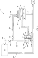
- Figure 1 shows schematically a pulping system 1, i.e. a process 1 for manufacturing fibre mass suspension.
- the process 1 comprises at least one primary pulper 2 and at least one secondary pulper 12 arranged in series with the at least one primary pulper 2.
- Figure 1 discloses only one primary pulper 2 and only one secondary pulper 2 but a number of the primary pulpers 2 and the secondary pulpers 12 may be higher than one in the fibre mass suspension manufacturing processes.
- the primary pulper 2 is used for producing fibre mass suspension by mixing together fibre material and water.
- the primary pulper 1 may be a vertical pulper and it comprises a pulping space 3, or a vat 3, into which water, as shown by arrow W, and fibre material, as shown by arrow FM, are supplied.
- the pulping space 3 is provided with a rotor 4 which is rotated by a not shown motor and which, when rotating at a high speed, defibres the fibre material FM supplied to the pulper 2, mixing it with water W.
- the consistency of the fibre mass suspension in the pulper 2 is typically 3 to 8%, but may also be 1 to 20%.
- the fibre material FM is a recycled fibre material but may also be a waste material recovered from a paper or cardboard manufacturing process or cellulose.
- the rotation of the rotor 4 generates a strong turbulence in the pulper 2 such that particles that are heavier than fibres, such as large fibre bundles and various impurities originating from the recycled fibre material, such as sand and pieces of plastic and metal, constituting a heavier matter, drift to the edges of the pulper 2.
- the lower part of the pulper 2 is provided with a screen plate 5 having a screening surface 6 provided with screen openings 7 extending through the screen plate 5 so as to enable a sufficiently defibred material to pass therethrough into an accept chamber 8 of the primary pulper 2.
- the portion of the fibre mass suspension which has passed through the screen openings 7 in the screen plate 5 into the accept chamber 8, is called the accept fraction of the primary pulper 2.
- the accept fraction is forwarded from the accept chamber 8 along an accept channel 9 of the primary pulper 2 to a further treatment process 11 in the fibre mass suspension manufacturing process.
- the further treatment process 11 in the fibre mass suspension manufacturing process may comprise, depending on an embodiment thereof, e.g. a number of, i.e.
- the fibre mass suspension may be supplied via precipitation to a short circulation of a paper or cardboard machine in order to be used in the manufacture of paper or cardboard.
- the reject channel 10 of the primary pulper 2 may be provided with a not shown valve, which in normal use is usually kept completely open, but when necessary, may be closed if, for one reason or another, the flow of the reject from the primary pulper 2 to the secondary pulper 12 is to be prevented.
- the lower part of the primary pulper 2 may also be provided with a junk trap (also omitted from Figure 1 for the sake of clarity) into which the heaviest components in the fibre mass suspension fall and wherefrom such components may be removed occasionally. Since the structure and operational principle of various pulpers suitable for use as the primary pulper 2 are generally known to a person skilled in the art, they will not be discussed in further detail herein.
- the reject fraction received from the primary pulper 2 is further screened and defibred in the secondary pulper 12.
- the secondary pulper 12 comprises a pulping space 13, or a pulping chamber 13, provided with a rotor 14 comprising rotor blades 15, the rotor 14 being rotated by a not shown motor.
- the secondary pulper 12 comprises further the screen plate 16 comprising a screening surface 17, the rotor blades 15 substantially extending over a radial extension of the screening surface 17 and rotating close to the screening surface 17.
- the secondary pulper 12 is thus a screening and defibring pulper wherein the screening and defibring are carried out by means of the rotor and the screen plate. Since the structure and operational principle of various pulpers suitable for use as the secondary pulper 12 are generally known to a person skilled in the art, they will not be discussed in further detail herein.
- the screening surface 17 of the screen plate 16 of the secondary pulper 12 of Figures 1 , 2 and 3 comprises two screening surface areas 17a, 17b, i.e. a first screening surface area 17a and a second screening surface area 17b, comprising respective screen openings 18a, 18b, i.e. first screen openings 18a and second screen openings 18b extending through the screen plate 16.
- Sizes of the first screen openings 18a in the first screening surface area 17a are substantially same over the first screening surface area 17a, as well as sizes of the second screen openings 18b in the second screening surface area 17b are substantially same over the second screening surface area 17b, but, however, the sizes of the first screen openings 18a in the first screening surface area 17a being smaller than the sizes of the second screen openings 18b in the second screening surface area 17b.
- the screen plate 16 of Figures 1 , 2 and 3 allows fibre material pieces of different sizes to pass the screening surface 17 of the screen plate 16 at different areas of the screening surface 17, fibre material pieces of only smaller size being able to pass the screen plate 16 only through the first screening surface area 17a and fibre material pieces of also bigger size being able to pass the screen plate 16 through the second screening surface area 17b.
- the fibre material passed through the screening surface 17 of the screen plate 16 forms the accept fraction of the fibre material to be processed.
- the screening surface 17 provides two different accept fractions, i.e. a fine accept fraction passed through the first screening surface area 17a and a coarse accept fraction passed through the second screening surface area 17b.
- the secondary pulper 12 further comprises respective separate accept chambers 19a, 19b for receiving the accept fractions passed through the screening surface 17 of the screen plate 16, i.e. a first accept chamber 19a or a fine accept chamber 19a for receiving the fine accept fraction passed through the first screening surface area 17a and a second accept chamber 19b or a coarse accept chamber 19b for receiving the coarse accept fraction passed through the second screening surface area 17b.
- a first accept chamber 19a or a fine accept chamber 19a for receiving the fine accept fraction passed through the first screening surface area 17a
- a second accept chamber 19b or a coarse accept chamber 19b for receiving the coarse accept fraction passed through the second screening surface area 17b.
- the first accept chamber 19a comprises an aggregate 20a for discharging the fine accept fraction out of the first accept chamber 19a of the secondary pulper 12 and the second accept chamber 19b comprises an aggregate 20b for discharging the coarse accept fraction out of the second accept chamber 19b of the secondary pulper 12.
- the secondary pulper 12 typically comprises an aggregate for supplying dilution water to the pulping space 13 in order to decrease the consistency of the fibre mass suspension in the pulping space 13, as well as an aggregate for discharging a reject fraction, i.e. the fibre mass suspension portion not penetrating the screen plate 16, out of the secondary pulper 12, and a junk trap into which the heaviest components in the fibre mass suspension fall and wherefrom such components may be removed occasionally.
- a reject fraction i.e. the fibre mass suspension portion not penetrating the screen plate 16, out of the secondary pulper 12, and a junk trap into which the heaviest components in the fibre mass suspension fall and wherefrom such components may be removed occasionally.
- the reject fraction aggregate 20c is disclosed in Figure 2 ,
- the fine accept fraction is discharged from the first accept chamber 19a of the secondary pulper 12 through the respective aggregate 20a and is forwarded to the further treatment process 11 in the fibre mass suspension manufacturing process along a fine accept channel 21a of the secondary pulper 12.
- the coarse accept fraction is discharged from the second accept chamber 19b of the secondary pulper 12 through the respective aggregate 20b and a coarse accept channel 21b of the secondary pulper 12 for further processing wherefrom it may be supplied to the further treatment process 11.
- At least a portion of the coarse accept fraction of the secondary pulper 12 is supplied through a back flow channel 22 or a recirculation channel 22 back to the primary pulper 2 for further processing.
- the secondary pulper 12 is able to provide, at the same time, a fine accept fraction flow to the further treatment process 11 as well as a coarse accept fraction flow back to the primary pulper 2, wherein the coarse accept fraction may be further processed for breaking it into smaller pieces of fibre material.
- a number of separate accept fraction flows in the example of Figures 1 to 3 , two separate accept fraction flows are provided at the same time, the fine accept fraction flow being forwarded towards the further treatment process 11 and, at the same time, the coarse accept fraction flow may be supplied back to the primary pulper 2 for further processing.
- the energy consumption of the pulping process is reduced because the fine accept fraction is continuously supplied out of the actual pulping process whereby no energy is used for pulping the fibre mass suspension portion that has already been sufficiently slushed.
- At least a portion of the coarse accept fraction of the secondary pulper 12, but in some operating situations all of the coarse accept fraction, may be supplied through a forward flow channel 23 forward to a coarse accept treatment process 24, wherein fibre material of the coarse accept fraction may still become at least to some extent slushed further for recovering fibres from the coarse accept fraction.
- the secondary pulper 12 is able to provide, at the same time, a fine accept fraction flow to the further treatment process 11 as well as a coarse accept fraction flow to the coarse accept treatment process 24 including at least one of at least one screening stage, washing and deflaking.
- the reject fraction of the secondary pulper 12 i.e. the fraction of the fibre material not passing through the screening surface 17 of the screen plate 16 may be supplied to a reject treatment including for example a drum screen for recovering fibres still remaining in the reject fraction.
- a portion of the coarse accept fraction of the secondary pulper 12 may be supplied through the back flow channel 22 back to the primary pulper 2 and at the same time a portion of the coarse accept fraction of the secondary pulper 12 may be supplied through the forward flow channel 23 forward to the coarse accept treatment process 24.
- a possible division of the coarse accept fraction into different flows i.e. a flow back to the pulping space 3 of the primary pulper 2 and a flow forward to the coarse accept treatment process 24, may be provided by controlling openings of valves 25, 26 arranged in the back flow channel 22 and the forward flow channel 23 respectively.
- the secondary pulper 12 is able to provide, at the same time, a fine accept fraction flow to the further treatment process 11 as well as a coarse accept fraction flows to the primary pulper 2 and to the coarse accept treatment process 24 for further processing the coarse accept fraction.
- the screening surface 17 of the screen plate 16 of the secondary pulper 12 comprises two different screening surface areas 17a, 17b with the screen openings 18a, 18b having different sizes.
- the number of the screening surface areas 17a, 17b with the screen openings 18a, 18b having different sizes may also be higher than two in the screen plate 16 of the secondary pulper 12.
- the screening surface of the screen plate may comprise two or more screening surface areas, i.e. at least two screening surface areas, and the size of the screen openings in each screening surface area is substantially same within the individual screening surface area but different from the size of the screen openings in any other screening surface area.
- a diameter of the screen openings 18a in the first screening surface area 17a may for example be substantially between 1 - 15 mm.
- a diameter of the screen openings 18b in at least one other screening surface area may for example be substantially between 6 - 32 mm.
- the diameter of the screen openings 18b is selected to be larger than the diameter of the screen openings 18a in spite of the partially overlapping ranges of the possible dimensioning of the openings 18a, 18b.
- the diameter of the screen openings 18a in the first screening surface area 17a is about 12 mm and the diameter of the screen openings 18b in the second screening surface area 17b is about 20 mm.
- a shape of the screen opening 18a, 18b is substantially round but many other shapes of the screen openings may be used.
- the screen plate 16 comprises altogether six separate screen plate segments 16a, 16b, 16c, 16d, 16e, 16f.
- the screen plate segments 16a, 16b, 16c having the screen openings 18a with smaller size provide the first screening surface area 17a in the screen plate 16 and the screen plate segments 16d, 16e, 16f having the screen openings 18b with larger size provide the second screening surface area 17b in the screen plate 16.
- the screen plate segments 16a to 16f may be supported to a screen plate frame 16' of which an outer ring is visible in Figures 2 and 3 .
- the screening surface 17 of the screen plate 16 comprises also two different screening surface areas 17a, 17b with the screen openings 18a, 18b having different sizes, each screening surface area 17a, 17b, however, being provided by a single screen plate segment 16g, 16h having a shape of a semi-circle and being supported to the screen plate frame 16'.
- surface areas of the screening surface areas 17a, 17b are about half, i.e. about 50 per cent, of the complete surface area of the screening surface 17 of the screen plate 16 but generally a surface area of a single screening surface are 17a, 17b may be between 20 - 80 per cent of the complete surface area of the screening surface 17.
- the division of the screening surface 17 into a number of different screening surface areas may, however, vary from that shown in Figures 1 , 2 and 3 in such a way that a surface area of at least one screening surface area is different from a surface area of any other screening surface area or from at least one other screening surface area provided in the screening surface 17 of the screen plate 16.
- An example of that kind of screen plate 16 and screening surface 17 therein is disclosed for example in Figures 5 and 6 later.
- Figure 4 shows schematically another pulping system 1, i.e. another process 1 for manufacturing fibre mass suspension.
- the process 1 of Figure 4 and the operation thereof resembles the process 1 of Figure 1 and the operation thereof, the differences between the embodiments of Figures 1 and 4 relating to the structure and operation of the primary pulper 2.
- the primary pulper 2 of Figure 4 comprises a pulping space 3, a rotor 4 and a screen plate 5 comprising a screening surface 6.
- the screening surface 6 comprises two screening surface areas 6a, 6b, i.e. a first screening surface area 6a and a second screening surface area 6b, comprising respective screen openings 7a, 7b, i.e. first screen openings 7a and second screen openings 7b extending through the screen plate 5.
- Sizes of the first screen openings 7a in the first screening surface area 6a are substantially same over the first screening surface area 6a, as well as sizes of the second screen openings 7b in the second screening surface area 6b are substantially same over the second screening surface area 6b, but, however, the size of the first screen openings 7a in the first screening surface area 6a being smaller than the size of the second screen openings 7b in the second screening surface area 6b.
- the first screening surface area 6a is located at an outer region of the pulping space 3 and the second screening surface area 6b is located at a central region of the pulping space 3 in such a manner that the first screening surface area 6a and the second screening surface area 6b have a common central axis and the first screening surface area 6a is arranged to surround the second screening surface area 6b.
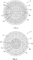
- Figure 5 shows schematically a front view of the screen plate 6 of the primary pulper 2 of Figure 4 .
- Figure 6 shows schematically a front view of another embodiment of the screen plate 5 which can be used in the primary pulper 2.
- the second screening surface area 6b is arranged to surround the first screening surface area 6a so that they have a common central axis.
- the first screening surface area 6a is to be located at a central region of the pulping space 3 and the second screening surface area 6b is to be located at an outer region of the pulping space 3.
- the screen plate 16 comprises two separate screen plate segments 5a, 5b, i.e. an outer segment 5a having a shape of a ring and an inner segment 5b having a shape of a circle.
- the screen plate segment 5a having the screen openings 7a with smaller size provides the first screening surface area 6a in the screen plate 5 and the screen plate segment 5b having the screen openings 7b with larger size provides the second screening surface area 6b in the screen plate 5.
- the screen plate segment 5b having the screen openings 7b with larger size provides the second screening surface area 6b in the screen plate 5.
- the embodiment of Figure 6 that is the other way around.
- the screen plate segments 5a, 5b may be supported to a screen plate frame 5' of which an outer ring is visible in Figures 5 and 6 .
- Each of the plate segments 5a, 5b could also be provided by a number of smaller segments.
- the primary pulper 2 comprises respective separate accept chambers 8a, 8b for receiving the accept fractions passed through the screening surface 6 of the screen plate 5, i.e. a first accept chamber 8a or a fine accept chamber 8a for receiving the fine accept fraction passed through the first screening surface area 6a and a second accept chamber 8b or a coarse accept chamber 8b for receiving the coarse accept fraction passed through the second screening surface area 6b.
- the accept chambers 8a, 8b thus have a common central axis, the first accept chamber 8a being arranged around the second accept chamber 8b, but the order of the accept chambers 8a, 8b could also be the other way around, in view of the embodiment of the screen plate 5 according to Figure 6 .
- the first screening surface area 6a of the screen plate 5 is thus set at the first accept chamber 8a and the second screening surface area 6b of the screen plate 5 is set at the second accept chamber 8b.
- the fine accept fraction is discharged from the first accept chamber 8a of the primary pulper 2 and forwarded to the further treatment process 11 in the fibre mass suspension manufacturing process along a fine accept channel 9a of the primary pulper 2.
- the coarse accept fraction is discharged from the second accept chamber 8b of the primary pulper 2 through a coarse accept channel 9b of the primary pulper 2 to the coarse accept treatment process 24 for further processing.
- the primary pulper 2 is thus able to provide, at the same time, a fine accept fraction flow to the further treatment process 11 as well as a coarse accept fraction flow to the coarse accept treatment process 24.
- After the coarse accept treatment process 24 at least a portion of the processed coarse accept may be supplied to the further treatment process 11 for example through a fine accept channel 27 of the coarse accept treatment process 24.
- the screening surface 6 of the screen plate 5 of the primary pulper 12 comprises two different screening surface areas 6a, 6b with the screen openings 7a, 7b having different sizes.
- the number of the screening surface areas with the screen openings having different sizes in the screen plate 5 of the primary pulper 2 may also be higher than two, in which case the primary pulper 2 is arranged to comprise respective number of separate accept chambers.
- the screen plates 16 of Figures 2 and 3 could also be utilized in the primary pulper 2.
- the screen plates 16 of Figures 2 and 3 could also be utilized in the secondary pulper 12. In these cases the accept chambers in the respective pulper should be arranged accordingly.
- the primary pulper 2 is equipped with the screen plate 5 comprising at least two different screening surface areas 6a, 6b and respective separate accept chambers 8a, 8b
- a conventional secondary pulper with a screen plate with openings of one size and a single accept chamber may also be used as the secondary pulper instead of the secondary pulper 12 shown in Figure 1 .
Landscapes
- Engineering & Computer Science (AREA)
- Mechanical Engineering (AREA)
- Life Sciences & Earth Sciences (AREA)
- Wood Science & Technology (AREA)
- Paper (AREA)
Abstract
Description
- The invention relates also to a secondary pulper for manufacturing fibre mass suspension, the secondary pulper comprising a pulping space equipped with a screen plate for dividing the fibre mass suspension into accept and reject fractions.
- The invention relates also to a process for manufacturing fibre mass suspension, the process comprising at least one primary pulper for mixing together fibre material and water so as to produce the fibre mass suspension and for dividing the fibre mass suspension into accept and reject fractions in the at least one primary pulper, and at least one secondary pulper for receiving at least a portion of the reject fraction from the at least one primary pulper and for dividing the reject fraction received from the at least one primary pulper into accept and reject fractions in the at least one secondary pulper.
- The invention relates also to a method for manufacturing fibre mass suspension, the method comprising producing the fibre mass suspension by mixing together fibre material and water in at least one primary pulper, dividing the fibre mass suspension into accept and reject fractions in the at least one primary pulper, supplying the reject fraction from the at least one primary pulper to at least one secondary pulper, and dividing the reject fraction received from the at least one primary pulper into accept and reject fractions in the at least one secondary pulper.
- At an initial stage of manufacturing fibre mass suspension, such as the fibre mass suspension to be used for manufacturing paper and cardboard, pulping may be used as one part of the process. The purpose of pulping is to defibre the fibre material to be fed to a primary pulper provided in the pulping system as well as to mix the fibre material with water to be fed to the primary pulper so as to produce the fibre mass suspension. The fibre material to be used may be e.g. cellulose or a recycled fibre material or a fibre-containing material from a paper or cardboard factory.
- Accept fraction, which is a portion of the fibre mass suspension that has passed through a screen plate remaining in the primary pulper, is supplied further to a further treatment process in the fibre mass suspension manufacturing process. A portion of the fibre mass suspension that has not passed the screen plate of the primary pulper, i.e. reject fraction of the primary pulper, is supplied further to a secondary pulper for further processing. The secondary pulper continues processing the reject received from the primary pulper, dividing it into accept and reject fractions. The accept fraction of the secondary pulper may be supplied from the secondary pulper to the further treatment process in the fibre mass suspension manufacturing process. Alternatively the accept fraction from the secondary pulper may be supplied back to the primary pulper for further processing in the primary pulper. The reject of the secondary pulper is supplied from the secondary pulper to a reject processing, which may for example be provided with a drum screen, the purpose of that being recovering fibres still remaining in the reject of the secondary pulper. Remaining material, i.e. the reject formed at the drum screen, in turn, is removed from the process, to be burned outside the process, for instance.
- An object of the present invention is to provide a novel secondary pulper and a novel process and method for manufacturing fibre mass suspension.
- The invention is characterized by the features of the independent claims.
- The invention is based on the idea of providing in a secondary pulper for manufacturing fibre mass suspension a number of accept fractions, whereby at least one fine accept fraction may be supplied from the secondary pulper to a further treatment process in the fibre mass suspension manufacturing process and at the same time at least one coarse accept fraction may be supplied from the secondary pulper to a further processing of the coarse accept fraction.
- An advantage of the invention is that it may be provided from a single secondary pulper at the same time both a fine accept fraction flow to the further treatment process as well as a coarse accept fraction flow for further processing of the coarse accept fraction, wherein fibres may be recovered from the coarse accept fraction. Concurrent flows of the fine accept fraction and the coarse accept fraction out of the secondary pulper allows for example a volume of the primary pulper to be decreased.
- Some embodiments of the invention are disclosed in the dependent claims.
- In the following the invention will be described in greater detail by means of preferred embodiments with reference to the accompanying drawings, in which
-
Figure 1 shows schematically a pulping system; -
Figure 2 shows schematically a front view of a secondary pulper and a screen plate therein; -
Figure 3 shows schematically a front view of a second screen plate; -
Figure 4 shows schematically another pulping system; -
Figure 5 shows schematically a front view of a third screen plate; and -
Figure 6 shows schematically a front view of a fourth screen plate. - For the sake of clarity, the figures show some embodiments of the invention in a simplified manner. Like reference numerals identify like elements in the figures.
-
Figure 1 shows schematically a pulping system 1, i.e. a process 1 for manufacturing fibre mass suspension. The process 1 comprises at least oneprimary pulper 2 and at least onesecondary pulper 12 arranged in series with the at least oneprimary pulper 2. For the sake of clarityFigure 1 discloses only oneprimary pulper 2 and only onesecondary pulper 2 but a number of theprimary pulpers 2 and thesecondary pulpers 12 may be higher than one in the fibre mass suspension manufacturing processes. - The
primary pulper 2 is used for producing fibre mass suspension by mixing together fibre material and water. The primary pulper 1 may be a vertical pulper and it comprises apulping space 3, or avat 3, into which water, as shown by arrow W, and fibre material, as shown by arrow FM, are supplied. Thepulping space 3 is provided with a rotor 4 which is rotated by a not shown motor and which, when rotating at a high speed, defibres the fibre material FM supplied to thepulper 2, mixing it with water W. The consistency of the fibre mass suspension in thepulper 2 is typically 3 to 8%, but may also be 1 to 20%. Typically, the fibre material FM is a recycled fibre material but may also be a waste material recovered from a paper or cardboard manufacturing process or cellulose. The rotation of the rotor 4 generates a strong turbulence in thepulper 2 such that particles that are heavier than fibres, such as large fibre bundles and various impurities originating from the recycled fibre material, such as sand and pieces of plastic and metal, constituting a heavier matter, drift to the edges of thepulper 2. - Over a middle part of the
pulper 2, the fibre material slowly settles downwards. The lower part of thepulper 2 is provided with ascreen plate 5 having ascreening surface 6 provided withscreen openings 7 extending through thescreen plate 5 so as to enable a sufficiently defibred material to pass therethrough into an acceptchamber 8 of theprimary pulper 2. The portion of the fibre mass suspension which has passed through thescreen openings 7 in thescreen plate 5 into the acceptchamber 8, is called the accept fraction of theprimary pulper 2. The accept fraction is forwarded from the acceptchamber 8 along an acceptchannel 9 of theprimary pulper 2 to afurther treatment process 11 in the fibre mass suspension manufacturing process. Thefurther treatment process 11 in the fibre mass suspension manufacturing process may comprise, depending on an embodiment thereof, e.g. a number of, i.e. one or more, screening stages and, therebetween or thereafter, removal of sand by means of vortex cleaners. After these phases, the fibre mass suspension may be supplied via precipitation to a short circulation of a paper or cardboard machine in order to be used in the manufacture of paper or cardboard. - The portion of the fibre mass suspension which accumulates on the edges of the
pulper 2 and contains various impurities, i.e. the reject fraction of theprimary pulper 2, is transferred substantially continuously along areject channel 10 of theprimary pulper 2 to thesecondary pulper 12. Thereject channel 10 of theprimary pulper 2 may be provided with a not shown valve, which in normal use is usually kept completely open, but when necessary, may be closed if, for one reason or another, the flow of the reject from theprimary pulper 2 to thesecondary pulper 12 is to be prevented. The lower part of theprimary pulper 2 may also be provided with a junk trap (also omitted fromFigure 1 for the sake of clarity) into which the heaviest components in the fibre mass suspension fall and wherefrom such components may be removed occasionally. Since the structure and operational principle of various pulpers suitable for use as theprimary pulper 2 are generally known to a person skilled in the art, they will not be discussed in further detail herein. - An embodiment of the process 1 and a structure and operation thereof, as well as an embodiment of a
secondary pulper 12 and a structure and operation thereof are discussed next in more detail and referring toFigures 1 ,2 and 3 , whereinFigure 2 shows schematically a front view of asecondary pulper 12 and ascreen plate 16 therein andFigure 3 shows schematically a front view of asecond screen plate 16. - The reject fraction received from the
primary pulper 2 is further screened and defibred in thesecondary pulper 12. Thesecondary pulper 12 comprises apulping space 13, or apulping chamber 13, provided with arotor 14 comprisingrotor blades 15, therotor 14 being rotated by a not shown motor. Thesecondary pulper 12 comprises further thescreen plate 16 comprising ascreening surface 17, therotor blades 15 substantially extending over a radial extension of thescreening surface 17 and rotating close to thescreening surface 17. When rotating therotor 14 and the blades thereof generate a strong turbulence close to the screening surface of the screen plate, thus effectively defibering the fibre material FM and forcing the defibered fibre material through screen openings in the screening surface of the screen plate into an accept chamber of the secondary pulper. Thesecondary pulper 12 is thus a screening and defibring pulper wherein the screening and defibring are carried out by means of the rotor and the screen plate. Since the structure and operational principle of various pulpers suitable for use as thesecondary pulper 12 are generally known to a person skilled in the art, they will not be discussed in further detail herein. - The
screening surface 17 of thescreen plate 16 of thesecondary pulper 12 ofFigures 1 ,2 and 3 comprises twoscreening surface areas screening surface area 17a and a secondscreening surface area 17b, comprisingrespective screen openings first screen openings 18a andsecond screen openings 18b extending through thescreen plate 16. Sizes of thefirst screen openings 18a in the firstscreening surface area 17a are substantially same over the firstscreening surface area 17a, as well as sizes of thesecond screen openings 18b in the secondscreening surface area 17b are substantially same over the secondscreening surface area 17b, but, however, the sizes of thefirst screen openings 18a in the firstscreening surface area 17a being smaller than the sizes of thesecond screen openings 18b in the secondscreening surface area 17b. The effect of this is that thescreen plate 16 ofFigures 1 ,2 and 3 allows fibre material pieces of different sizes to pass thescreening surface 17 of thescreen plate 16 at different areas of thescreening surface 17, fibre material pieces of only smaller size being able to pass thescreen plate 16 only through the firstscreening surface area 17a and fibre material pieces of also bigger size being able to pass thescreen plate 16 through the secondscreening surface area 17b. - The fibre material passed through the
screening surface 17 of thescreen plate 16 forms the accept fraction of the fibre material to be processed. In the example ofFigures 1 ,2 and 3 thescreening surface 17 provides two different accept fractions, i.e. a fine accept fraction passed through the firstscreening surface area 17a and a coarse accept fraction passed through the secondscreening surface area 17b. - The
secondary pulper 12 further comprises respectiveseparate accept chambers screening surface 17 of thescreen plate 16, i.e. afirst accept chamber 19a or afine accept chamber 19a for receiving the fine accept fraction passed through the firstscreening surface area 17a and asecond accept chamber 19b or acoarse accept chamber 19b for receiving the coarse accept fraction passed through the secondscreening surface area 17b. In thesecondary pulper 12 the firstscreening surface area 17a of thescreen plate 16 is thus set at the first acceptchamber 19a and the secondscreening surface area 17b of thescreen plate 16 is set at the second acceptchamber 19b. - The first accept
chamber 19a comprises an aggregate 20a for discharging the fine accept fraction out of the first acceptchamber 19a of thesecondary pulper 12 and the second acceptchamber 19b comprises an aggregate 20b for discharging the coarse accept fraction out of the second acceptchamber 19b of thesecondary pulper 12. In addition to theaggregates secondary pulper 12 typically comprises an aggregate for supplying dilution water to thepulping space 13 in order to decrease the consistency of the fibre mass suspension in thepulping space 13, as well as an aggregate for discharging a reject fraction, i.e. the fibre mass suspension portion not penetrating thescreen plate 16, out of thesecondary pulper 12, and a junk trap into which the heaviest components in the fibre mass suspension fall and wherefrom such components may be removed occasionally. For the sake of clarity, of these aggregates only the reject fraction aggregate 20c is disclosed inFigure 2 , the other two aggregates being omitted in the Figures. - The fine accept fraction is discharged from the first accept
chamber 19a of thesecondary pulper 12 through therespective aggregate 20a and is forwarded to thefurther treatment process 11 in the fibre mass suspension manufacturing process along a fine acceptchannel 21a of thesecondary pulper 12. - The coarse accept fraction is discharged from the second accept
chamber 19b of thesecondary pulper 12 through therespective aggregate 20b and a coarse acceptchannel 21b of thesecondary pulper 12 for further processing wherefrom it may be supplied to thefurther treatment process 11. - According to an embodiment, at least a portion of the coarse accept fraction of the
secondary pulper 12, but in some operating situations all of the coarse accept fraction, is supplied through aback flow channel 22 or arecirculation channel 22 back to theprimary pulper 2 for further processing. In this operating situation thesecondary pulper 12 is able to provide, at the same time, a fine accept fraction flow to thefurther treatment process 11 as well as a coarse accept fraction flow back to theprimary pulper 2, wherein the coarse accept fraction may be further processed for breaking it into smaller pieces of fibre material. - In prior art solutions, there has been only a single accept chamber in the secondary pulper as well as a single screening surface area with screen openings of one size, thus providing only one accept fraction. Depending on the operation situation in the prior art, this accept fraction has been supplied at a time either back to the
primary pulper 2 for further processing or forwarded towards thefurther treatment process 11 in the fibre mass suspension manufacturing process 1. - In the present invention, a number of separate accept fraction flows, in the example of
Figures 1 to 3 , two separate accept fraction flows are provided at the same time, the fine accept fraction flow being forwarded towards thefurther treatment process 11 and, at the same time, the coarse accept fraction flow may be supplied back to theprimary pulper 2 for further processing. This means that all the time at least a portion of the accept fraction of thesecondary pulper 12 may be forwarded to thefurther treatment process 11, whereby for example a volume of theprimary pulper 2 may be decreased in view to the prior art solutions. Also the energy consumption of the pulping process is reduced because the fine accept fraction is continuously supplied out of the actual pulping process whereby no energy is used for pulping the fibre mass suspension portion that has already been sufficiently slushed. - According to an embodiment, at least a portion of the coarse accept fraction of the
secondary pulper 12, but in some operating situations all of the coarse accept fraction, may be supplied through aforward flow channel 23 forward to a coarse accepttreatment process 24, wherein fibre material of the coarse accept fraction may still become at least to some extent slushed further for recovering fibres from the coarse accept fraction. In this operating situation thesecondary pulper 12 is able to provide, at the same time, a fine accept fraction flow to thefurther treatment process 11 as well as a coarse accept fraction flow to the coarse accepttreatment process 24 including at least one of at least one screening stage, washing and deflaking. After the coarse accepttreatment process 24 at least a portion of the processed coarse accept may be supplied to thefurther treatment process 11. The reject fraction of thesecondary pulper 12, i.e. the fraction of the fibre material not passing through thescreening surface 17 of thescreen plate 16 may be supplied to a reject treatment including for example a drum screen for recovering fibres still remaining in the reject fraction. - According to an embodiment, a portion of the coarse accept fraction of the
secondary pulper 12 may be supplied through theback flow channel 22 back to theprimary pulper 2 and at the same time a portion of the coarse accept fraction of thesecondary pulper 12 may be supplied through theforward flow channel 23 forward to the coarse accepttreatment process 24. - A possible division of the coarse accept fraction into different flows, i.e. a flow back to the
pulping space 3 of theprimary pulper 2 and a flow forward to the coarse accepttreatment process 24, may be provided by controlling openings ofvalves back flow channel 22 and theforward flow channel 23 respectively. In this operating situation thesecondary pulper 12 is able to provide, at the same time, a fine accept fraction flow to thefurther treatment process 11 as well as a coarse accept fraction flows to theprimary pulper 2 and to the coarse accepttreatment process 24 for further processing the coarse accept fraction. - In the example above the
screening surface 17 of thescreen plate 16 of thesecondary pulper 12 comprises two differentscreening surface areas screen openings screening surface areas screen openings screen plate 16 of thesecondary pulper 12. Thus, in general terms, the screening surface of the screen plate may comprise two or more screening surface areas, i.e. at least two screening surface areas, and the size of the screen openings in each screening surface area is substantially same within the individual screening surface area but different from the size of the screen openings in any other screening surface area. - A diameter of the
screen openings 18a in the firstscreening surface area 17a may for example be substantially between 1 - 15 mm. A diameter of thescreen openings 18b in at least one other screening surface area may for example be substantially between 6 - 32 mm. According to the solution disclosed herein, the diameter of thescreen openings 18b is selected to be larger than the diameter of thescreen openings 18a in spite of the partially overlapping ranges of the possible dimensioning of theopenings screen openings 18a in the firstscreening surface area 17a is about 12 mm and the diameter of thescreen openings 18b in the secondscreening surface area 17b is about 20 mm. - In the embodiments disclosed above a shape of the
screen opening - Referring back to
Figure 2 , thescreen plate 16 comprises altogether six separatescreen plate segments screen plate segments screen openings 18a with smaller size provide the firstscreening surface area 17a in thescreen plate 16 and thescreen plate segments screen openings 18b with larger size provide the secondscreening surface area 17b in thescreen plate 16. Thescreen plate segments 16a to 16f may be supported to a screen plate frame 16' of which an outer ring is visible inFigures 2 and 3 . - Referring to
Figure 3 , which discloses an example of asecond screen plate 16, thescreening surface 17 of thescreen plate 16 comprises also two differentscreening surface areas screen openings surface area screen plate segment - Further referring to
Figures 1 ,2 and 3 , surface areas of thescreening surface areas screening surface 17 of thescreen plate 16 but generally a surface area of a single screening surface are 17a, 17b may be between 20 - 80 per cent of the complete surface area of thescreening surface 17. The division of thescreening surface 17 into a number of different screening surface areas may, however, vary from that shown inFigures 1 ,2 and 3 in such a way that a surface area of at least one screening surface area is different from a surface area of any other screening surface area or from at least one other screening surface area provided in thescreening surface 17 of thescreen plate 16. An example of that kind ofscreen plate 16 andscreening surface 17 therein is disclosed for example inFigures 5 and 6 later. -
Figure 4 shows schematically another pulping system 1, i.e. another process 1 for manufacturing fibre mass suspension. The process 1 ofFigure 4 and the operation thereof resembles the process 1 ofFigure 1 and the operation thereof, the differences between the embodiments ofFigures 1 and4 relating to the structure and operation of theprimary pulper 2. - The
primary pulper 2 ofFigure 4 comprises apulping space 3, a rotor 4 and ascreen plate 5 comprising ascreening surface 6. Thescreening surface 6 comprises twoscreening surface areas screening surface area 6a and a secondscreening surface area 6b, comprisingrespective screen openings first screen openings 7a andsecond screen openings 7b extending through thescreen plate 5. Sizes of thefirst screen openings 7a in the firstscreening surface area 6a are substantially same over the firstscreening surface area 6a, as well as sizes of thesecond screen openings 7b in the secondscreening surface area 6b are substantially same over the secondscreening surface area 6b, but, however, the size of thefirst screen openings 7a in the firstscreening surface area 6a being smaller than the size of thesecond screen openings 7b in the secondscreening surface area 6b. - In the embodiment of the
screen plate 6 of theprimary pulper 2 ofFigure 4 , the firstscreening surface area 6a is located at an outer region of thepulping space 3 and the secondscreening surface area 6b is located at a central region of thepulping space 3 in such a manner that the firstscreening surface area 6a and the secondscreening surface area 6b have a common central axis and the firstscreening surface area 6a is arranged to surround the secondscreening surface area 6b. The same can be observed inFigure 5 , which shows schematically a front view of thescreen plate 6 of theprimary pulper 2 ofFigure 4 . -
Figure 6 shows schematically a front view of another embodiment of thescreen plate 5 which can be used in theprimary pulper 2. In the embodiment ofFigure 6 the secondscreening surface area 6b is arranged to surround the firstscreening surface area 6a so that they have a common central axis. By using thescreen plate 5 ofFigure 6 the firstscreening surface area 6a is to be located at a central region of thepulping space 3 and the secondscreening surface area 6b is to be located at an outer region of thepulping space 3. - In the embodiments of
Figures 5 and 6 thescreen plate 16 comprises two separatescreen plate segments outer segment 5a having a shape of a ring and aninner segment 5b having a shape of a circle. In the embodiment ofFigure 5 thescreen plate segment 5a having thescreen openings 7a with smaller size provides the firstscreening surface area 6a in thescreen plate 5 and thescreen plate segment 5b having thescreen openings 7b with larger size provides the secondscreening surface area 6b in thescreen plate 5. In the embodiment ofFigure 6 that is the other way around. - The
screen plate segments Figures 5 and 6 . Each of theplate segments - Referring back to
Figure 4 , theprimary pulper 2 comprises respective separate acceptchambers screening surface 6 of thescreen plate 5, i.e. a first acceptchamber 8a or a fine acceptchamber 8a for receiving the fine accept fraction passed through the firstscreening surface area 6a and a second acceptchamber 8b or a coarse acceptchamber 8b for receiving the coarse accept fraction passed through the secondscreening surface area 6b. The acceptchambers chamber 8a being arranged around the second acceptchamber 8b, but the order of the acceptchambers screen plate 5 according toFigure 6 . In theprimary pulper 2 the firstscreening surface area 6a of thescreen plate 5 is thus set at the first acceptchamber 8a and the secondscreening surface area 6b of thescreen plate 5 is set at the second acceptchamber 8b. - The fine accept fraction is discharged from the first accept
chamber 8a of theprimary pulper 2 and forwarded to thefurther treatment process 11 in the fibre mass suspension manufacturing process along a fine acceptchannel 9a of theprimary pulper 2. - The coarse accept fraction is discharged from the second accept
chamber 8b of theprimary pulper 2 through a coarse acceptchannel 9b of theprimary pulper 2 to the coarse accepttreatment process 24 for further processing. In this embodiment theprimary pulper 2 is thus able to provide, at the same time, a fine accept fraction flow to thefurther treatment process 11 as well as a coarse accept fraction flow to the coarse accepttreatment process 24. After the coarse accepttreatment process 24 at least a portion of the processed coarse accept may be supplied to thefurther treatment process 11 for example through a fine acceptchannel 27 of the coarse accepttreatment process 24. - In the example of
Figures 4 to 6 thescreening surface 6 of thescreen plate 5 of theprimary pulper 12 comprises two differentscreening surface areas screen openings screen plate 5 of theprimary pulper 2 may also be higher than two, in which case theprimary pulper 2 is arranged to comprise respective number of separate accept chambers. - Furthermore, instead of using the
screen plates 5 ofFigures 5 and 6 in theprimary pulper 2, thescreen plates 16 ofFigures 2 and 3 could also be utilized in theprimary pulper 2. Similarly, instead of using thescreen plates 16 ofFigures 2 and 3 in thesecondary pulper 12, thescreen plates 5 ofFigures 5 and 6 could also be utilized in thesecondary pulper 12. In these cases the accept chambers in the respective pulper should be arranged accordingly. - If the
primary pulper 2 is equipped with thescreen plate 5 comprising at least two differentscreening surface areas chambers secondary pulper 12 shown inFigure 1 . - It will be obvious to a person skilled in the art that, as the technology advances, the inventive concept can be implemented in various ways. The invention and its embodiments are not limited to the examples described above but may vary within the scope of the claims.
Claims (15)
- A secondary pulper (12) for manufacturing fibre mass suspension, the secondary pulper (12) comprising a pulping space (13) equipped with a screen plate (16) for dividing the fibre mass suspension into accept and reject fractions, the screen plate (16) comprising a screening surface (17) provided with screen openings extending through the screen plate (16), characterized in that
the screening surface (17) of the screen plate (16) comprises at least two screening surface areas (17a, 17b), a size of at least one screen opening (18a, 18b) in at least one screening surface area (17a, 17b) being different from a size of at least one screen opening (18a, 18b) in at least one other screening surface area (17a, 17b), and that
the secondary pulper (12) comprises at least two accept chambers (19a, 19b) respective to the screening surface areas (17a, 17b) and separate from each other for receiving different accept fractions into different accept chambers (19a, 19b). - A secondary pulper as claimed in claim 1, characterized in that the secondary pulper (12) comprises a first accept chamber (19a) for receiving a fine accept fraction and a second accept chamber (19b) for receiving a coarse accept fraction.
- A secondary pulper as claimed in claim 1 or 2, characterized in that the sizes of the screen openings (18a, 18b) in each individual screening surface area (17a, 17b) are substantially same but different from the sizes of the screen openings (18a, 18b) in any other screening surface area (17a, 17b).
- A secondary pulper as claimed in any one of the preceding claims, characterized in that screen plate (16) comprises a number of separate screen plate segments (16a, 16b, 16c, 16d, 16e, 16f, 16g, 16h), each screen plate segment (16a, 16b, 16c, 16d, 16e, 16f, 16g, 16h) providing at least a part of a single screening surface area (17a, 17b) and comprising screen openings (18a, 18b) having substantially same size.
- A secondary pulper as claimed in any one of the preceding claims, characterized in that a surface area of at least one screening surface area (17a, 17b) is at least 50 per cent of a surface area of a complete screening surface (17) of the screen plate (16).
- A secondary pulper as claimed in any one of the preceding claims, characterized in that the screen plate (16) comprises two screening surface areas (17a, 17b) with different sizes of the screen openings (18a, 18b) in each screening surface area (17a, 17b).
- A secondary pulper as claimed in claim 6, characterized in that the screening surface (17) of the screen plate (16) is divided into two screening surface areas (17a, 17b) along a diameter of the screen plate (16).
- A secondary pulper as claimed in any one of the preceding claims, characterized in that the screening surface areas have a common central axis, whereby one screening surface area is arranged around the other screening surface area.
- A process (1) for manufacturing fibre mass suspension, the process (2) comprising at least one primary pulper for mixing together fibre material (FM) and water (W) so as to produce the fibre mass suspension and for dividing the fibre mass suspension into accept and reject fractions in the at least one primary pulper (2), and at least one secondary pulper (12) for receiving at least a portion of the reject fraction from the at least one primary pulper (2) and for dividing the reject fraction received from the at least one primary pulper (2) into accept and reject fractions in the at least one secondary pulper (12),
characterized in that
the at least one secondary pulper (12) comprises at least two accept chambers (19a, 19b) separate from each other for receiving different accept fractions into different accept chambers (19a, 19b). - A process as claimed in claim 9, characterized in that
the at least one secondary pulper comprises a first accept chamber (19a) for receiving a fine accept fraction and a second accept chamber (19b) for receiving a coarse accept fraction, and that the fine accept fraction from the at least one secondary pulper (12) is arranged to be supplied to a further treatment process (11) and the coarse accept fraction is arranged to be supplied for further processing. - A process as claimed in claim 9 or 10, characterized in that the at least one secondary pulper (12) comprises the first accept chamber (19a) for receiving the fine accept fraction and the second accept chamber (19b) for receiving the coarse accept fraction, and that the fine accept fraction from the at least one secondary pulper (12) is arranged to be supplied to the further treatment process (11) and at least a portion of the coarse accept fraction from the at least one secondary pulper (12) is arranged to be supplied to the pulping space (3) of the at least one primary pulper (2) for further processing.
- A process as claimed in any one of claims 9 to 11, characterized in that the process (1) comprises a coarse accept treatment process (24) including at least one of at least one screening stage, washing and deflaking of the coarse accept, the coarse accept treatment process (24) arranged to receive at least a portion of the coarse accept fraction from at least one of the at least one primary pulper (2) and the at least one secondary pulper (12) for further processing.
- A method for manufacturing fibre mass suspension, the method comprising producing the fibre mass suspension by mixing together fibre material (FM) and water (W) in at least one primary pulper (2), dividing the fibre mass suspension into accept and reject fractions in the at least one primary pulper (2), supplying the reject fraction from the at least one primary pulper (2) to at least one secondary pulper (12), and dividing the reject fraction received from the at least one primary pulper (12) into accept and reject fractions in the at least one secondary pulper (12), characterized by dividing the accept fraction in the at least one secondary pulper (12) into a fine accept fraction and a coarse accept fraction in the respective pulper (12), and supplying the fine accept fraction to a further treatment process (11) and supplying the coarse accept fraction for further processing.
- A method as claimed in claim 13, characterized by supplying at least a portion of the coarse accept fraction from the at least one secondary pulper (12) to a pulping space (3) of the at least one primary pulper (2) for further processing.
- A method as claimed in claim 13 or 14, characterized by supplying at least a portion of the coarse accept fraction from the at least one secondary pulper (12) to a coarse accept treatment process (24) including at least one of at least one screening stage, washing and deflaking of the coarse accept.
Applications Claiming Priority (1)
| Application Number | Priority Date | Filing Date | Title |
|---|---|---|---|
| FI20185942A FI20185942A1 (en) | 2018-11-06 | 2018-11-06 | Screen plate, pulper, process and method for manufacturing fibre mass suspension |
Publications (1)
| Publication Number | Publication Date |
|---|---|
| EP3650601A1 true EP3650601A1 (en) | 2020-05-13 |
Family
ID=68468599
Family Applications (1)
| Application Number | Title | Priority Date | Filing Date |
|---|---|---|---|
| EP19207087.8A Withdrawn EP3650601A1 (en) | 2018-11-06 | 2019-11-05 | Pulper and method for manufacturing fibre mass suspension |
Country Status (3)
| Country | Link |
|---|---|
| EP (1) | EP3650601A1 (en) |
| CN (1) | CN111139676B (en) |
| FI (1) | FI20185942A1 (en) |
Cited By (6)
| Publication number | Priority date | Publication date | Assignee | Title |
|---|---|---|---|---|
| AT17433U1 (en) * | 2020-03-24 | 2022-04-15 | Voith Patent Gmbh | pulper |
| WO2022194315A1 (en) * | 2021-03-17 | 2022-09-22 | Boltersdorf Hans Joachim | Kneader and method for operating a kneader |
| WO2023084144A1 (en) * | 2021-11-14 | 2023-05-19 | Pr Pulping Oy | An apparatus and a method for screening a suspension |
| CN117358587A (en) * | 2023-12-07 | 2024-01-09 | 吉林农业科技学院 | Seed screening machine and seed screening method |
| WO2024189001A1 (en) * | 2023-03-13 | 2024-09-19 | Andritz Küsters Gmbh | Method and device for producing a fibrous web |
| WO2025090171A1 (en) * | 2023-10-25 | 2025-05-01 | Kadant Black Clawson Llc | Bedplates having graduated openings for pulp processing units |
Families Citing this family (2)
| Publication number | Priority date | Publication date | Assignee | Title |
|---|---|---|---|---|
| CN113510631A (en) * | 2021-08-18 | 2021-10-19 | 格力大松(宿迁)生活电器有限公司 | Sandblasting machine and sandblasting system |
| CN115287929B (en) * | 2022-07-18 | 2025-11-21 | 安德里茨(中国)有限公司 | Pulper and pulper rotor |
Citations (8)
| Publication number | Priority date | Publication date | Assignee | Title |
|---|---|---|---|---|
| US2796807A (en) * | 1954-06-22 | 1957-06-25 | Fibreboard Paper Products Corp | Method and apparatus for treating waste paper stock |
| GB1574645A (en) * | 1976-03-17 | 1980-09-10 | Black Clawson Co | Method and apparatus forrecovering paper fibres from waste paper containing materials |
| US4283275A (en) * | 1979-05-04 | 1981-08-11 | Escher Wyss Gmbh | Apparatus for processing waste paper |
| GB2161091A (en) * | 1984-07-06 | 1986-01-08 | Voith Gmbh J M | Process for the preparation of waste paper |
| JPS63288287A (en) * | 1987-05-20 | 1988-11-25 | 株式会社 岩科製作所 | Pulper |
| JPH01213490A (en) * | 1987-05-28 | 1989-08-28 | Aikawa Tekko Kk | Pulper |
| DE202005000332U1 (en) * | 2005-01-11 | 2005-03-17 | Voith Paper Patent Gmbh | Pulper for crushing and suspending pulp |
| DE102006031904B3 (en) * | 2006-07-07 | 2007-10-04 | Gw Fasertechnik Gmbh | Paper pulping assembly for paper recovery and recycling has rotor surrounded by ring |
Family Cites Families (2)
| Publication number | Priority date | Publication date | Assignee | Title |
|---|---|---|---|---|
| FI120629B (en) * | 2007-09-14 | 2009-12-31 | Metso Paper Inc | Apparatus and method for preparing a pulp suspension |
| AT512395B1 (en) * | 2012-04-24 | 2013-08-15 | Andritz Ag Maschf | Process for the dissolution of fibrous materials |
-
2018
- 2018-11-06 FI FI20185942A patent/FI20185942A1/en not_active Application Discontinuation
-
2019
- 2019-11-05 EP EP19207087.8A patent/EP3650601A1/en not_active Withdrawn
- 2019-11-06 CN CN201911075783.9A patent/CN111139676B/en active Active
Patent Citations (8)
| Publication number | Priority date | Publication date | Assignee | Title |
|---|---|---|---|---|
| US2796807A (en) * | 1954-06-22 | 1957-06-25 | Fibreboard Paper Products Corp | Method and apparatus for treating waste paper stock |
| GB1574645A (en) * | 1976-03-17 | 1980-09-10 | Black Clawson Co | Method and apparatus forrecovering paper fibres from waste paper containing materials |
| US4283275A (en) * | 1979-05-04 | 1981-08-11 | Escher Wyss Gmbh | Apparatus for processing waste paper |
| GB2161091A (en) * | 1984-07-06 | 1986-01-08 | Voith Gmbh J M | Process for the preparation of waste paper |
| JPS63288287A (en) * | 1987-05-20 | 1988-11-25 | 株式会社 岩科製作所 | Pulper |
| JPH01213490A (en) * | 1987-05-28 | 1989-08-28 | Aikawa Tekko Kk | Pulper |
| DE202005000332U1 (en) * | 2005-01-11 | 2005-03-17 | Voith Paper Patent Gmbh | Pulper for crushing and suspending pulp |
| DE102006031904B3 (en) * | 2006-07-07 | 2007-10-04 | Gw Fasertechnik Gmbh | Paper pulping assembly for paper recovery and recycling has rotor surrounded by ring |
Cited By (7)
| Publication number | Priority date | Publication date | Assignee | Title |
|---|---|---|---|---|
| AT17433U1 (en) * | 2020-03-24 | 2022-04-15 | Voith Patent Gmbh | pulper |
| WO2022194315A1 (en) * | 2021-03-17 | 2022-09-22 | Boltersdorf Hans Joachim | Kneader and method for operating a kneader |
| WO2023084144A1 (en) * | 2021-11-14 | 2023-05-19 | Pr Pulping Oy | An apparatus and a method for screening a suspension |
| WO2024189001A1 (en) * | 2023-03-13 | 2024-09-19 | Andritz Küsters Gmbh | Method and device for producing a fibrous web |
| WO2025090171A1 (en) * | 2023-10-25 | 2025-05-01 | Kadant Black Clawson Llc | Bedplates having graduated openings for pulp processing units |
| CN117358587A (en) * | 2023-12-07 | 2024-01-09 | 吉林农业科技学院 | Seed screening machine and seed screening method |
| CN117358587B (en) * | 2023-12-07 | 2024-02-20 | 吉林农业科技学院 | Seed screening machine and seed screening method |
Also Published As
| Publication number | Publication date |
|---|---|
| CN111139676A (en) | 2020-05-12 |
| FI20185942A1 (en) | 2020-05-07 |
| CN111139676B (en) | 2022-04-15 |
Similar Documents
| Publication | Publication Date | Title |
|---|---|---|
| EP3650601A1 (en) | Pulper and method for manufacturing fibre mass suspension | |
| US5564572A (en) | Method and apparatus for screening waste paper pulp | |
| KR100331376B1 (en) | Apparatus for screening waste paper plup | |
| US8262849B2 (en) | Apparatus and method for manufacturing fibre mass suspension | |
| AT511367B1 (en) | Pulper arrangement and method for dissolving fiber material | |
| CN102459755A (en) | Method for treating a fiber suspension and screening devices for carrying out the same | |
| US7163604B2 (en) | Production of fiber suspension from waste paper | |
| US6651679B2 (en) | Process for the breaking and cleaning of contaminant-containing raw paper stocks, in particular of recovered paper | |
| US9370779B2 (en) | Method and arrangement | |
| JP5750095B2 (en) | Apparatus, system and method for the treatment of cellulose pulp | |
| JP3360773B2 (en) | Waste paper pulp sorting method and apparatus | |
| JPH1053986A (en) | Defibrating and screening of recycle fiber material and apparatus therefor | |
| US8444807B2 (en) | Method for preparing paper pulp from recycled paper containing contaminants | |
| JPH0143439Y2 (en) | ||
| JPH03279483A (en) | Papermaking disaggregation machine also used as duster | |
| CN113249998A (en) | Waste paper pulping system | |
| Carstens | Technology in fibre recovery | |
| JPH06192982A (en) | Device for macerating and dust removing for papermaking |
Legal Events
| Date | Code | Title | Description |
|---|---|---|---|
| PUAI | Public reference made under article 153(3) epc to a published international application that has entered the european phase |
Free format text: ORIGINAL CODE: 0009012 |
|
| STAA | Information on the status of an ep patent application or granted ep patent |
Free format text: STATUS: THE APPLICATION HAS BEEN PUBLISHED |
|
| AK | Designated contracting states |
Kind code of ref document: A1 Designated state(s): AL AT BE BG CH CY CZ DE DK EE ES FI FR GB GR HR HU IE IS IT LI LT LU LV MC MK MT NL NO PL PT RO RS SE SI SK SM TR |
|
| AX | Request for extension of the european patent |
Extension state: BA ME |
|
| STAA | Information on the status of an ep patent application or granted ep patent |
Free format text: STATUS: REQUEST FOR EXAMINATION WAS MADE |
|
| 17P | Request for examination filed |
Effective date: 20201016 |
|
| RBV | Designated contracting states (corrected) |
Designated state(s): AL AT BE BG CH CY CZ DE DK EE ES FI FR GB GR HR HU IE IS IT LI LT LU LV MC MK MT NL NO PL PT RO RS SE SI SK SM TR |
|
| STAA | Information on the status of an ep patent application or granted ep patent |
Free format text: STATUS: EXAMINATION IS IN PROGRESS |
|
| 17Q | First examination report despatched |
Effective date: 20240422 |
|
| STAA | Information on the status of an ep patent application or granted ep patent |
Free format text: STATUS: THE APPLICATION IS DEEMED TO BE WITHDRAWN |
|
| 18D | Application deemed to be withdrawn |
Effective date: 20240823 |