EP3650367A1 - Closing valve made of sheet and bag with closing valve - Google Patents
Closing valve made of sheet and bag with closing valve Download PDFInfo
- Publication number
- EP3650367A1 EP3650367A1 EP18827792.5A EP18827792A EP3650367A1 EP 3650367 A1 EP3650367 A1 EP 3650367A1 EP 18827792 A EP18827792 A EP 18827792A EP 3650367 A1 EP3650367 A1 EP 3650367A1
- Authority
- EP
- European Patent Office
- Prior art keywords
- valve
- film
- downstream
- upstream
- flow path
- Prior art date
- Legal status (The legal status is an assumption and is not a legal conclusion. Google has not performed a legal analysis and makes no representation as to the accuracy of the status listed.)
- Granted
Links
Images






Classifications
-
- B—PERFORMING OPERATIONS; TRANSPORTING
- B65—CONVEYING; PACKING; STORING; HANDLING THIN OR FILAMENTARY MATERIAL
- B65D—CONTAINERS FOR STORAGE OR TRANSPORT OF ARTICLES OR MATERIALS, e.g. BAGS, BARRELS, BOTTLES, BOXES, CANS, CARTONS, CRATES, DRUMS, JARS, TANKS, HOPPERS, FORWARDING CONTAINERS; ACCESSORIES, CLOSURES, OR FITTINGS THEREFOR; PACKAGING ELEMENTS; PACKAGES
- B65D33/00—Details of, or accessories for, sacks or bags
- B65D33/01—Ventilation or drainage of bags
-
- F—MECHANICAL ENGINEERING; LIGHTING; HEATING; WEAPONS; BLASTING
- F16—ENGINEERING ELEMENTS AND UNITS; GENERAL MEASURES FOR PRODUCING AND MAINTAINING EFFECTIVE FUNCTIONING OF MACHINES OR INSTALLATIONS; THERMAL INSULATION IN GENERAL
- F16K—VALVES; TAPS; COCKS; ACTUATING-FLOATS; DEVICES FOR VENTING OR AERATING
- F16K15/00—Check valves
- F16K15/14—Check valves with flexible valve members
-
- B—PERFORMING OPERATIONS; TRANSPORTING
- B65—CONVEYING; PACKING; STORING; HANDLING THIN OR FILAMENTARY MATERIAL
- B65D—CONTAINERS FOR STORAGE OR TRANSPORT OF ARTICLES OR MATERIALS, e.g. BAGS, BARRELS, BOTTLES, BOXES, CANS, CARTONS, CRATES, DRUMS, JARS, TANKS, HOPPERS, FORWARDING CONTAINERS; ACCESSORIES, CLOSURES, OR FITTINGS THEREFOR; PACKAGING ELEMENTS; PACKAGES
- B65D2205/00—Venting means
Definitions
- the present invention relates to a closing valve made of a sheet and a bag provided with a closing valve made of a sheet, such as a deaerating bag for food.
- Flexible resin bags are widely used to contain food and other items.
- articles that are averse to coming into contact with the outside air are generally contained in resin sealed bags that can block the outside air.
- a bag body made of resin is used in which air or other gas is filled into the bag, that is, the bag body contains the gas and serves as a cushion.
- deaerating bags which contain clothes and futon bedding and discharge the air in the bag to reduce the volume and not to take space for storage, have also become popular.
- Some of the contained items may generate a gas during containment, such as fermented food.
- a kind of the sealed bag that is provided with a closing valve through which a contained fluid item is taken out or unnecessary gas is discharged without allowing outside air to enter the bag is commonly used.
- Patent Literature 1 described a check valve (V), including an exterior film (1) made of a flexible resin sheet and having flexibility and a valve body sheet (2), wherein: the check valve has a substantially cylindrical shape with a flat cross section due to formation of a side seal (3) in which both sides of exterior films (1a, 1b) facing each other are bonded together; a fluid passage (P) is provided inside; the at least one valve body sheet (2) is provided so as to be sandwiched between the exterior films (1a, 1b) facing each other; a bond portion (21a), which is a part of an attachment surface (21) that is a surface on one side of the valve body sheet (2), is bonded to the exterior film (1a) on one side; a close-contact surface (22) that is a surface on the other side of the valve body sheet (2) is capable of getting close to and away from the exterior film (1b) on the other side facing the close-contact surface (22) or a valve body sheet (2') bonded to the exterior film (1b) on the other side; and the fluid passage (P
- Patent Literature 1 The invention described in Patent Literature 1 is to provide a check valve in which a fluid passage can be forcibly opened by bringing the handle portions on both sides across the operation side opening portion close to each other in a direction along the exterior film, allowing the fluid passage to be opened simply with hand and allowing a fluid to easily and quickly pass through, and the check valve in which unexpected fluid leakage is less likely to occur while an appearance is not affected.
- FIG. 1(A) An image of the operation of a conventional check valve provided in a flexible resin bag ( FIG. 1(A) ) will be briefly described with reference to FIG. 10 with an example where the increasing pressure in the bag varies, with reference to the atmospheric pressure assumed to be 0.
- the indication “inside” means an inside of a containment space of the bag, that is, the inside of the bag
- the indication “outside” means an outside of the bag, that is, an atmosphere side.
- the "inside” is an upstream side
- the "outside” is a downstream side.
- the thick lines that extend longitudinally at the center and divide the "inside” from the “outside” are pressure difference positions between the internal pressure of the bag and the outside of the bag and indicate valve mounting positions such as bag end portions.
- valve 10(D) (e.g., +0.5 atmospheres of internal pressure with respect to external pressure of 0) in which the difference between the internal pressure of the bag and the external pressure is reduced by the deaeration to a ratio similar to that of FIG. 10(B) again, and then it becomes the state of FIG. 10(E) in which the internal pressure of the bag and the external pressure are balanced again or the internal pressure of the bag is slightly lower than the external pressure.
- the valve closes the air passage by self-adhesion of the sheet, that is, film.
- the conventional check valve also has a sufficient function as an air-filled bag such as a cushioning material (air cushion material) or a deaerating bag such as a clothing compression bag.
- the first solution is to prevent a reverse flow, and to reliably and quickly close the valve in a reverse flow (when there is a pressure difference in the fluid in the flow path).
- the second solution is to maintain for a long time a state in which the reverse flow is prevented.
- Patent Literature 2 describes a closing valve in which a substantially cylindrical air passage (41) having a flat cross section is formed by providing both sides of exterior films (43a) (43b) facing each other as closed portions (43e) (43f); opening portions (43c) (43g) are formed on both end sides of the air passage (41); and a valve body sheet (42) is provided inside, wherein: the valve body sheet (42) includes a fixing portion (42a) attached to the exterior film (43b), and a first flap portion (42b) and a second flap portion (42c) movable around the fixing portion (42a); the first flap portion (42b) is in close contact with a surface (43i) of the other exterior film (43a) on the air passage side, whereby air flow from one end side to the other end side of the air passage (41) is blocked; and the second flap portion (42c) is in close contact with the surface (43i) of the other exterior film (43a) on the air passage side, whereby air flow from the other end side to one
- Patent Literatures 3 and 4 also describe closing valves each including two valve portions of an upstream valve portion and a downstream valve portion.
- This new problem relates to the behavior of the valve in balanced state with a very small pressure difference.
- the inventor has found that there is a problem that a small amount of fluid (air in case of a deaerating bag) near the valve outlet is sucked in when the state changes from the state of FIG. 10(C) to the state of FIG. 10(D) , and further to the state of FIG. 10(E) .
- the valve outlet cannot be closed by the self-adhesion of the valve portion alone, which increases the possibility that the valve cannot be closed.
- the bag can be forcibly pressurized, or in the case of an air-filled bag, the pressure in the bag can be quickly increased by injecting air through a nozzle or the like, and hence a relatively large pressure difference can be ensured and the time of balanced state can be shortened.
- the contents generate gas and in the case where the contents have a pressure difference generated by the generated gas such as coffee beans, if the content amount (coffee beans) is small, the amount of gas generated is also small, and the balanced state may become long.
- An object of the present invention is to provide a closing valve capable of effectively exerting the function of a check valve when the pressure difference is large and also even when the balanced state where the pressure difference is small continues for a long time.
- the present invention provides a closing valve having a flexible and substantially cylindrical shape and made of a sheet, in which: exterior films are arranged above and below in an outside and both sides of the exterior film are closed to form closed portions; one end side serves as an inflow portion to a forward flow, and the other end side serves as an outflow portion to the forward flow; a flow path for the forward flow and a reverse flow flowing in an opposite direction of the forward flow is composed; and the flow path includes a valve portion that restricts movement of a fluid in the flow path, wherein: three regions of an upstream valve portion, a downstream valve portion, and a buffer portion are included.
- the upstream valve portion is positioned on an upstream side of the forward flow, and the downstream valve portion is positioned on a downstream side of the forward flow with respect to the upstream valve portion. Between the upstream valve portion and the downstream valve portion, a buffer portion in which a fluid in the flow path is retained is formed.
- closedness of the flow path in the buffer portion is lower than closedness of the downstream valve portion.
- closedness of the flow path in the upstream valve portion is lower than the closedness of the downstream valve portion.
- a length in a flow direction of the fluid in the flow path is longer than a length of at least any one of the upstream valve portion and the downstream valve portion.
- At least any one of the upper and lower exterior films in the buffer portion may include a hardly pressure-sensitive adhesion portion, and due to the hardly pressure-sensitive adhesion portion, a space between the upper and lower exterior films in the buffer portion may be of hardly adhesive property as compared to a space between the upper and lower exterior films in an external valve portion.
- At least the upstream valve portion of the valve portions may include, as a valve body film, at least one film composing a check valve that is opened in the forward flow and closed in the reverse flow.
- the valve body film opens or closes the flow path by opening or coming into close contact with a film overlapped on an upper surface of the valve body film, and the valve body film is fixed to a film overlapped on a lower surface of the valve body film in a sealed state on an upstream side of the valve body film, and is conducted to the buffer portion on the downstream side of the valve body film so that the valve body film and the film overlapped on the lower surface of the valve body film compose a buffer continuous portion.
- the valve body film may be provided only in the upstream valve portion and not in the downstream valve portion, a tip space may be arranged between a downstream end of the valve body film and a downstream end of the exterior film, and the tip space is a space in which the upper and lower exterior films directly face each other, and includes a lowly closed space composing the buffer portion and a highly closed space positioned on a downstream side of the buffer portion and composing the downstream valve portion.
- the closedness of the flow path is greatly influenced by the width of the flow path and the adhesion between the films composing the flow path. Therefore, as specific means, the flow path width of the flow path can be made narrower in the downstream valve portion than a flow path width in the buffer portion and a flow path width in the upstream valve portion.
- the adhesion between the films can be made lower in the buffer portion than adhesion in the upstream valve portion and adhesion in the downstream valve portion.
- the closing valve according to the present invention can be mounted on a bag when used.
- the present invention provides a bag and the closing valve fixed to a sheet that composes a containment space of the bag, wherein: the upstream valve portion includes an upstream valve film, the upstream valve film is a check valve that includes a fixing portion fixed to one of the exterior films and a flap portion that extends from the fixing portion toward the outflow portion; and the fixing portion is arranged, in a flow direction of the forward flow, at the same position as, or downstream of, a pressure difference position, which is a sealed portion of the bag that divides inside and outside of the containment space by sealing the sheets, which compose the bag, to each other.
- the upper and lower positions only indicate the relative positional relationship, and do not specify the absolute position.
- the closing valve is to be attached to the bag in various orientations, and the bag itself is to be used in various orientations. Whatever satisfies the relative positional relationship defined by the present invention, no matter which orientation it is used, should be considered as an embodiment of the present invention.
- the present invention is capable of providing a closing valve that is capable of effectively exerting the function of a check valve not only when the pressure difference is large but also when the pressure difference is small and the balanced state continues for a long time, and a bag that includes the closing valve.
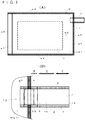
- FIG. 1(A) An overall view (plan view) is illustrated in FIG. 1(A) , in particular, with a food storage bag provided with the deaerating valve as the sealed bag w.
- FIG. 1(B) is an enlarged plan view of the closing valve v according to the present invention provided in the sealed bag w of FIG. 1(A) .
- the bag for food is the flexible resin sealed bag w.
- the sealed bag w is formed by overlapping two sheets of a substantially rectangular upper sheet w1 and lower sheet w2 and sealing three sides w3, w4, and w5 of the rectangle to close.
- the upper sheet w1 and the lower sheet w2 are sheets formed of a flexible synthetic resin such as polyethylene.
- the hatched portions in FIGS. 1(A) and 1(B) are a sealed portion h to which the seal is applied.
- the sealed portion h can be formed by heat sealing.
- a remaining one side w6, which is opened without being closed, is an opening portion (hereinafter, referred to as an opening portion w6 as necessary) of the sealed bag w, and a fastener w7 is provided.
- the fastener w7 a well-known one used for closing a synthetic resin bag opening portion may be adopted.
- the fastener w7 is composed of concave and convex portions provided over substantially the entire length of one side that is the opening portion w6, and the opening portion is closed by fitting the concave and convex portions together so as to be openable and closable.
- the sealed bag w is not limited to the substantially rectangular one shown in FIG. 1(A) , and the shape and dimension of the sealed bag w are not particularly limited. For example, it may be implemented as a polygon other than a quadrangle, a circle, or other streamline shape.
- the closing valve v which is the deaerating valve, is provided on one of the three closed sides of the sealed bag w.
- the heat sealing is performed by sandwiching the closing valve v between the sides of the upper sheet w1 and the lower sheet w2, whereby the closing valve v can be attached to the sealed bag w.
- the sealed bag w is a deaerating bag in which, for example, food that generates a gas during storage such as coffee or fermented food, clothes or futon bedding whose bulk is reduced by depressurization, or the like is contained in an interior space, that is, a containment space w0, of the sealed bag w. After the heat sealing, this contained item is contained in the containment space w0 through the opening portion w6 by opening the fastener w7.
- the heat sealing may be performed after the contained item is arranged between the upper sheet w1 and the lower sheet w2 before the heat sealing.
- the one side w6 provided with the fastener w7 may also be heat sealed, and the opening portion w6 may be formed in the sealed bag by opening by a user and the opening portion w6 may be closed by the fastener w7 after opened.
- the containment space w0 side of the sealed bag w is defined as the inside of the bag, and the outside of the containment space w0 is defined as the outside of the bag.
- the closing valve v is a flexible, flat, substantially cylindrical valve, and uses the interior space of the cylindrical closing valve v as a flow path v0 for fluid (air in this example), thereby allowing movement of fluid between the containment space w0 of the sealed bag w and the outside of the sealed bag w.
- the closing valve v includes an upstream valve portion a and a downstream valve portion c, which restrict the movement of fluid in the flow path v0 ( FIG. 1(B) ).
- the flow path is defined such that the inside of the bag is the upstream side and the outside of the bag is the downstream side.
- the upstream valve portion a is arranged upstream with respect to the downstream valve portion c.
- a portion of the closing valve v between the upstream valve portion a on the upstream side and the downstream valve portion c on the downstream side composes a buffer portion b for retaining fluid.
- the upstream valve portion a is provided at a pressure difference position between an internal pressure and an external pressure of the sealed bag w.
- the pressure difference position is, in this example, a position where the closing valve v is mounted in the sealed bag w, and coincides with the sealed portion h.
- the closing valve v is formed by overlapping two sheets of flexible, synthetic resin exterior films 1 such as polyethylene.
- the exterior film 1 arranged above in FIGS. 2(A) and 2(B) is referred to as an upper exterior film la
- the exterior film 1 arranged below the upper exterior film la is referred to as a lower exterior film 1b.
- the both sides of the exterior films la and 1b, which are overlapped and face each other, are closed portions 2 that are closed.
- the closed portion 2 is a portion that is sealed as a side seal (hereinafter referred to as a side seal portion 2).
- the side seal portion 2 may be formed by well-known means such as heat sealing.
- the overlapped exterior film 1 is formed into a flat cylindrical shape with both ends open.
- a fluid passage (the flow path v0) is formed between the upper exterior film la and the lower exterior film 1b.
- one end side of the exterior film 1 serves as an inflow portion 12 that opens to the inside of the sealed bag w
- the other end side of the exterior film 1 serves as an outflow portion 13 that opens to the outside of the sealed bag w.
- upstream and downstream and inflow and outflow are each based on a flow direction of a forward flow in which the closing valve allows a fluid to pass through unless otherwise noted, and in a case where they are based on a flow direction of a reverse flow in a direction reverse to the flow direction of the forward flow, the same is clearly indicated.
- the upstream valve portion a is positioned in a region including the sealed portion h defining the inside of the sealed bag w from the outside thereof, which is the pressure difference position in the flow path v0 as described above.
- the upstream valve portion a is a check valve that allows movement of a fluid from the upstream side to the downstream side of the flow path v0, that is, the forward flow, and restricts movement of the fluid from the downstream side to the upstream side, that is, the reverse flow.
- the upstream valve portion a includes a valve body film made of synthetic resin such as polyethylene.
- the valve body film of the upstream valve portion a is referred to as an upstream valve film 3 where necessary.
- the upstream valve film 3 is arranged between the upper exterior film 1a and the lower exterior film 1b, and the upper surface of the upstream valve film 3 is not fixed to the upper exterior film 1a but is released on the upstream side and the downstream side thereof.
- the lower surface of the upstream valve film 3 is fixed to the lower exterior film 1b in a sealed state on the upstream side thereof, and is released on the downstream side thereof.
- the upstream valve film 3 has a flap portion 31 that performs open/close operations of the valve and a fixing portion 32 that fixes the flap portion 31 to the lower exterior film 1b.
- the upstream valve film 3 moves up and down in response to pressure fluctuations in the flow path v0, and the upper surface of the upstream valve film 3 (flap portion 31) comes into close contact with the lower surface of the upper exterior film 1a to block the flow path v0, and the upper surface of the upstream valve film 3 (flap portion 31) is opened from the lower surface of the upper exterior film 1a to open the flow path v0.
- the upstream valve film 3 can be attached between the exterior films 1 together with the adhesion between the upper and lower exterior films 1a and 1b.
- the region where the spots are marked is a portion to be adhered by the side seal portion 2.
- a non-welding film 33 to be described later is provided on the upstream valve film 3 before the upstream valve film 3 is attached between the upper and lower exterior films 1.
- the upper exterior film 1a, the upstream valve film 3, and the lower exterior film 1b, which are integrated at the side seal portion 2 are inserted ( FIG. 4(B) ) between the upper sheet w1 and the lower sheet w2, and performing the heat sealing enables the sealed bag w to be formed, the upstream valve portion a to be formed on the closing valve v, and the closing valve v to be attached to the sealed bag w simultaneously ( FIG. 2(A) ). That is, the fixing portion 32 of the upstream valve film 3 is formed by the heat sealing of the sealed portion h. Therefore, in the upstream valve film 3, the fixing portion 32 indicates the pressure difference position.
- the fixing portion 32 In the state before attachment to the sealed bag w, the fixing portion 32 is not formed, and the upstream valve film 3 is only fixed to the upper and lower exterior films 1 at the side seal portion 2.
- the fixing portion 32 is formed by the heat sealing.
- the non-welding film 33 is arranged on the upper surface of the upstream valve film 3 so that the upper surface of the upstream valve film 3 opposite to the fixing portion 32 is not welded to the upper exterior film 1a by heat sealing of the sealed portion h ( FIGS. 1(B) , 2 , 3 , and 4 ).
- the non-welding film 33 is a film that is not heat-welded at the heat sealing temperature of the sealed portion h, and prevents welding with the upper exterior film 1a.
- the non-welding film 33 itself is fixed to the upstream valve film 3 via a welding film 34 ( FIG. 3(B) ), which is heat-welded.
- the welding film 34 is overlapped on the non-welding film 33 by lamination.
- a well-known method other than heat sealing such as using an adhesive is employed.
- a heat-resistant ink can be applied.
- the non-welding film 33 is provided on the upstream valve film 3 within a range not overlapping the side seal portion 2 so as not to block the sealing by the side seal portion 2.
- the non-welding film 33 has a width substantially equal to the distance between the side seal portions 2 ( FIGS. 1(B) and 3(A) ).
- the non-welding film 33 that overlaps the side seal portion 2 is not excluded.
- the side of the exterior film 1 may be closed by providing an extension portion w8 extending to the outside of the sealed portion h with respect to the side w5 to which the closing valve v of the sealed bag w is attached, and by providing an auxiliary sealed portion h1 crossing the sealed portion h, coming into contact with the side seal portion 2, and extending parallel to the side seal portion.
- the auxiliary sealed portion h1 is provided from the inside of the sealed bag w to the extension portion w8.
- the auxiliary sealed portion h1 can be formed on the upper sheet w1 and the lower sheet w2 by heat sealing when the sealed bag w is formed together with the sealed portion h.
- the upper and lower exterior films 1 and the upstream valve film 3 may be formed of a single synthetic resin film such as polyethylene or a laminate, and a surface (i.e., the lower surface of the upper exterior film 1a, the upper surface of the lower exterior film 1b, and the upper surface of the upstream valve film 3) composing the inner surface of the flow path v0 is preferably a self-adhesive surface.
- the film including the self-adhesive surface on one side may be a coextrusion die obtained by coextruding a film base material such as polyethylene and a self-adhesive thermoplastic resin such as ethylene vinyl acetate copolymer resin (EVA), or a coating die obtained by coating a film base material such as polyethylene with an adhesive.
- a coextrusion die obtained by coextruding a film base material such as polyethylene and a self-adhesive thermoplastic resin such as ethylene vinyl acetate copolymer resin (EVA), or a coating die obtained by coating a film base material such as polyethylene with an adhesive.
- the upstream valve portion a is implemented as a check valve that includes the upstream valve film 3 described above, and as shown in FIG. 3(B) , the upper surface of the flap portion 31 of the upstream valve film 3 comes into close contact with the lower surface of the opposing upper exterior film 1a, and the closing valve v is brought into a valve closed state.
- the flap portion 31 can be provided on the lower surface thereof with a hardly pressure-sensitive adhesion part 35 on the surface facing the exterior film 1 (lower exterior film 1b) ( FIG. 3(B) ), but may be provided without the hardly pressure-sensitive adhesion part 35.
- a valve portion includes at least two valve portions, that is, the upstream valve portion a and the downstream valve portion c, which is positioned downstream with respect to the upstream valve portion, and the buffer portion b for retaining the fluid in the flow path v0 is provided in the upstream valve portion a and the downstream valve portion c.
- the upper and lower exterior films 1 directly face each other, and the surface (i.e., the lower surface of the upper exterior film 1a and the upper surface of the lower exterior film 1b) composing the inner surface of the flow path v0 is a self-adhesive surface as described above, and one or both of the exterior films 1 are provided with a hardly pressure-sensitive adhesion portion 4.
- the hardly pressure-sensitive adhesion portion 4 is made to be of hardly adhesive property as compared to a case where the self-adhesive surfaces face each other.
- the hardly pressure-sensitive adhesion portion 4 does not have adhesiveness and prevents the two exterior films 1 from coming into close contact.
- the hardly pressure-sensitive adhesion portion 4 is provided on the lower surface of the upper exterior film 1a, but may be provided on the upper surface of the lower exterior film 1b, or may be provided on both the upper exterior film 1a and the lower exterior film 1b.
- the buffer portion b provides an inflated space in which fluid is retained.
- the hardly pressure-sensitive adhesion portion 4 can be formed by using well-known ink that reduces the self-adhesiveness of the exterior film 1 to coat the ink on the exterior film 1.
- FIG. 2(B) in order to make the arrangement of the hardly pressure-sensitive adhesion portion 4 easy to understand, the thickness of the hardly pressure-sensitive adhesion portion 4 is emphasized to be larger than that of the other components.
- the downstream valve portion c does not include a valve body film in this example.
- the exterior film 1 does not include the hardly pressure-sensitive adhesion portion 4 such as the buffer portion b. Therefore, in the downstream valve portion c, the lower surface of the self-adhesive upper exterior film 1a and the upper surface of the self-adhesive lower exterior film 1b directly face each other, and they come into close contact with each other as an adhesive portion 5 to close the gap between the upper and lower exterior films 1 ( FIG. 3(B) ).
- the downstream valve portion c limits the reverse flow as well as the forward flow of fluid.
- the downstream valve portion c is opened by receiving pressure from a fluid. Therefore, unless the internal pressure of the flow path v0 in the buffer portion b becomes higher than that of the downstream side of the downstream valve portion c, the downstream valve portion c maintains the valve closed state by the self-adhesion.
- the fluid is a gas
- the downstream valve portion c is closed unless the internal pressure of the buffer portion b becomes higher than the external pressure.
- the closedness of the flow path depends on the thickness, flexibility, shape, and the like of the vertically opposed films composing the flow path v0, and the largest factors that influence the closedness include two factors of the adhesiveness and the width of the flow path.
- the adhesiveness which is the first factor, is about the level of adhesiveness of the vertically opposed films composing the flow path v0, and the higher the adhesiveness is, the higher the closedness of the flow path is, and the lower the adhesiveness is, the lower the closedness of the flow path is.
- Adhesiveness can be measured by the T-type peel strength test, but it can also be measured by the opening test of the cylindrical body (a test in which a cylindrical body is produced by vertically opposed films, and after these films are held in a predetermined range by a predetermined force and brought into close contact, a fluid is introduced from one end of the cylindrical body, and the pressure of the fluid when the fluid comes out from the other end is measured).
- the width of the flow path which is the second factor, is about the length of the width of the flow path (i.e., the distance in the direction orthogonal to the flow direction of the fluid in the flow path v0), and when the adhesiveness is the same, the smaller the width of the flow path is, the higher the closedness of the flow path is.
- the operation of the closing valve v will be briefly described with reference to FIG. 5 .
- the details of the structure of each valve portion will be omitted and only the operation will be described.
- the upstream side refers to the upstream side with respect to the buffer portion b in the fluid flow path v0
- the downstream side refers to the downstream side with respect to the buffer portion b in the fluid flow path v0.
- both the upstream valve portion a and the downstream valve portion c are closed, and the buffer portion b is also contracted to narrow the width between the two exterior films 1.
- the buffer portion b Since the buffer portion b is arranged in a bag outside section of the flow path v0, the buffer portion b can be inflated relatively freely without being affected by the internal pressure of the sealed bag w as in a bag inside section from the surface side of the exterior film 1, and can sufficiently perform the function of retaining the fluid as a buffer.
- the cylindrical closing valve can expand and contract without being affected by the internal pressure of the bag. Therefore, in the present invention, the above effect can be exerted more remarkably.
- the buffer portion b In order for the buffer portion b to effectively exert its function, it is necessary to configure the buffer portion b to be inflated by the fluid during forward flow (upon exiting through the flow path v0 from the containment space w0).
- the buffer portion b needs to be configured in such a manner that the closedness of the flow path is lower than that of the downstream valve portion c, and more preferably, the closedness of the flow path is lower than that of both the upstream valve portion a and the downstream valve portion c.
- the closedness is determined by the adhesiveness.
- the upstream valve portion a and the downstream valve portion c have the equal closedness, and the closedness of the buffer portion b having the hardly pressure-sensitive adhesion portion 4 is lower than that of both of the valve portions a and c.
- the width of the flow path v0 of the buffer portion b can be made wider than that of the downstream valve portion c, and more preferably, it can be made wider than that of both of the upstream valve portion a and the downstream valve portion c.
- the buffer portion b may not be inflated by the fluid, and hence measures for preventing this is taken.
- the length of the fluid in the flow direction of the flow path v0 is longer than that of at least one of the upstream valve portion a and the downstream valve portion c, and more desirably, the length of the fluid in the flow direction of the flow path v0 is longer than that of both of the upstream valve portion a and the downstream valve portion c.
- the length of the upstream valve portion a and the downstream valve portion c indicates the length of a portion functioning as a valve portion to close the flow path
- the length of the upstream valve portion a is the length of a region of the flap portion 31 downstream with respect to the fixing portion 32 and a region not overlapping the hardly pressure-sensitive adhesion portion 4.
- the length of the buffer portion b is the length of a region where the hardly pressure-sensitive adhesion portion 4 is provided.
- the length of the downstream valve portion c is the length of a region where the adhesive portion 5 is provided downstream with respect to the hardly pressure-sensitive adhesion portion 4.
- the length of the fluid in the flow direction of the flow path v0 is longer than that of both of the upstream valve portion a and the downstream valve portion c.
- the space between the upstream valve film 3 and the lower exterior film 1b overlapped the lower surface of the upstream valve film 3 is sealed by the fixing portion 32 on the upstream side thereof, and is conducted to the buffer portion b on the downstream side thereof.
- some of the fluid having entered the buffer portion b may be introduced into the space between the upstream valve film 3 and the lower exterior film 1b as shown in FIG. 3(B) , and this space will be described as a buffer continuous portion d in the following description.
- the downstream valve portion c may be provided with a valve body film, similarly to the upstream valve portion a.
- a downstream valve film 6 is fixed to one of the exterior films 1 as the valve body film.
- the downstream valve film 6 includes a sub flap portion 61 and a sub fixing portion 62 having the same functions as the flap portion 31 and the fixing portion 32. That is, in the downstream valve portion c, the downstream valve film 6 is fixed to the upper surface of the lower exterior film 1b by the sub fixing portion 62.
- the sub flap portion 61 extends toward the downstream side from the sub fixing portion 62.
- the sub flap portion 61 is provided with a sub non-welding film 63 similar to the non-welding film 33.
- the sub fixing portion 62 is heat-sealed by a well-known heat sealing device from the surface side of one exterior film 1 (in this example, the lower exterior film 1b) to which the downstream valve film 6 is attached at the time of manufacturing the closing valve v before attaching it to the sealed bag w, so that the sub fixing portion 62 crossing the rectangular sub flap portion 61 in a plan view can be formed ( FIG. 8(B) , which is referred to in a third embodiment, shows a state in which the sub flap portion 61 is viewed in a plan view).
- the lower surface of the upper exterior film 1a and the upper surface of the lower exterior film 1b, which compose the inner surface of the flow path v0, have the self-adhesiveness described above as the adhesive portion 5.
- the opposing surfaces may not have the self-adhesiveness.
- the upper surface of the downstream valve film 6 has the self-adhesiveness.
- the opposing surfaces may not have the self-adhesiveness.
- each of the exterior films 1 is composed of a first composition film 10 and a second composition film 11, which are formed separately from each other.
- the upper exterior film 1a is composed of two films, which are an upper first composition film 10a and an upper second composition film 11a
- the lower exterior film 1b is composed of a lower first composition film 10b and a lower second composition film 11b.
- the upper first composition film 10a and the lower first composition film 10b are overlapped to form a flat cylinder whose side portions are sealed by the side seal portion 20.
- the upper second composition film 11a and a lower second composition film 11b are also overlapped to form a flat cylinder whose side portions are sealed by a sub side seal portion 21 ( FIG. 8(B) ).
- FIG. 8(B) sub side seal portion
- a dark (dense) spot indicates a region to be referred to as the side seal portion 20
- a thin (sparse) spot indicates a region to be referred to as the sub side seal portion 21.
- the cylinder composed by the second composition film 11 has a larger cylinder diameter than that of the cylinder composed by the first composition film 10. As shown in FIG. 8(B) , the width across the flow path v0 of the second composition film 11 is larger than that of the first composition film 10.
- each of the second composition films 11 is indirectly via a part of the sealed bag w or directly connected to each of the first composition films 10 at the pressure difference position to provide another part of the flow path v0 extending from the first composition film 10 toward the outside of the bag.
- the second composition film 11 is fixed to the sealed bag w by the sealed portion h and is indirectly connected to the first composition film 10 ( FIGS. 7(B) and 8(B) ).
- the second composition film 11 can be fixed directly to the first composition film 10.
- Each of the second composition films 11 is arranged on the outside of the bag, and the flow path v0 provided is defined as a section on the outside of the bag.
- the upper first composition film 10a and the non-welding film 33 on the lower first composition film 10b provide the inflow portion 12, and the upper and lower second composition films 11 and 11 provide the outflow portion 13.
- the upper and lower first composition films 10 and 10 include an interior portion 14 that extends from the pressure difference position toward the outside of the bag and is interposed between the second composition films 11 and 11.
- the upstream valve film 3 is arranged above and fixed to one of the first composition films 10 (the lower first composition film 10b).
- the downstream valve film 6 is arranged above and fixed to one of the second composition films 11 (the lower second composition film 11b).
- the downstream valve portion c includes the downstream valve film 6 as described above. However, similarly to the first embodiment, the downstream valve portion c may not include the downstream valve film 6.
- the region of the hardly pressure-sensitive adhesion portion 4 between a tip end of the interior portion 14 and the downstream valve film 6 is defined as the buffer portion b.
- the space between the upper surface of the upper first composition film 10a of the interior portion 14 and the lower surface of the upper second composition film 11a facing the upper surface of the upper first composition film 10a, and the space between the lower surface of the lower first composition film 10b of the interior portion 14 and the upper surface of the lower second composition film 11b compose the buffer continuous portion d.
- the buffer continuous portion d is conducted to the buffer portion b, and a part of the fluid flows into the buffer continuous portion d.
- the self-adhesiveness of the lower surface of the upper first composition film 10a is greater than the self-adhesiveness of the upper surface of the upper first composition film 10a.
- the upper surface of the lower second composition film 11b does not have the self-adhesiveness.
- the self-adhesiveness of the upper surface of the upper first composition film 10a is smaller than the self-adhesiveness of the lower surface of the upper first composition film 10a, but is larger than the self-adhesiveness of the upper surface of the lower second composition film 11b.
- the self-adhesiveness of the lower surface of the upper first composition film 10a is large, the self-adhesiveness of the upper surface of the upper first composition film 10a is moderate, and the self-adhesiveness of the upper surface of the lower second composition film 11b is small.
- at least a surface of the upstream valve film 3 opposite to the non-welding film 33 has a moderate self-adhesiveness.
- the lower surface of the lower first composition film 10b also has a moderate self-adhesiveness.
- the self-adhesiveness of the upper surface of the lower first composition film 10b is large.
- the self-adhesiveness of the downstream valve film 6 in the third embodiment is the same as that described in the second embodiment.
- a fourth embodiment will be described with reference to FIG. 9 .
- FIG. 9(A) is a sectional view of the closing valve according to the fourth embodiment, and FIG. 9(B) is a plan view of the same.
- the closing valve is a modification of the first embodiment, only the main differences are described, and the closing valve is substantially the same as that of the first embodiment in that the same reference numerals are given and no description is given.
- the inflow portion 12 in this example has a structure in that the containment space w0 of the bag w is opened in a planar shape.
- the upper exterior film 1a is elongated inside the containment space w0, and a filter 51 such as a nonwoven fabric is arranged therebelow.
- the upper exterior film 1a and the filter 51 inside the containment space w0 have substantially the same size and shape, and the periphery thereof is fixed by the heat seal of a filter fixing portion 52.
- the fluid inside the containment space w0 is introduced into the flow path v0 through the filter 51, whereby fine powder and the like can be prevented from being introduced into the closing valve or flowing out to the outside.
- the upstream valve film 3 is fixed by the filter fixing portion 52 with the filter 51 positioned outside the bag w from the position of the sealed portion h, and the filter fixing portion 52 serves also as the fixing portion 32.
- the upstream valve film 3 has the flap portion 31 on the downstream side of the filter fixing portion 52 and the fixing portion 32.
- the upstream valve film 3, together with the upper and lower exterior films 1a and 1b, is sandwiched between the upper sheet w1 and the lower sheet w2 of the bag w and fixed by the sealed portion h.
- this structure allows the closing valve v in a state where the upstream valve film 3 is fixed by the filter fixing portion 52 with the filter 51 to be inserted between the upper sheet w1 and the lower sheet w2 of the bag w to be heat-sealed.
- One of the filter fixing portion 52 and the sealed portion h may be located outside the other, or the filter fixing portion 52 and the sealed portion h may be located at the same position. However, if the filter fixing portion 52 and the sealed portion h are located at the same position, the heat sealing property may be lowered, and hence it is preferable to make the seal positions different.
- the upstream valve portion a is positioned downstream with respect to the heat seal of the filter fixing portion 52.
- inflow portion 12 can also be adopted in each of the above-described embodiments.
- the exterior film 1 (the upper exterior film 1a and the lower exterior film 1b) does not include the hardly pressure-sensitive adhesion portion 4, and both the lower surface of the upper exterior film 1a with self-adhesiveness and the upper surface of the lower exterior film 1b with self-adhesiveness directly face each other and they make close contact each other as the adhesive portion 5. Therefore, there is no difference between the buffer portion b and the downstream valve portion c in that the buffer portion b and the downstream valve portion c close between the upper and lower exterior films 1.
- the buffer portion b and the downstream valve portion c are common in that they compose a tip space between the downstream end of the upstream valve film 3, which is a valve body film, and the downstream end of the exterior film 1 (the upper exterior film 1a and the lower exterior film 1b).
- This tip space is divided, depending on the level of closedness, into a highly closed space composing the downstream valve portion c and a lowly closed space composing the buffer portion b.
- the downstream valve portion c is a portion having the smallest width of the flow path v0 without the valve body film
- the buffer portion b is a portion having a larger width of the flow path v0 than that of the highly closed space composing the downstream valve portion c.
- a downstream valve point seal 53 is provided at the center of the flow path v0, thereby narrowing the width of the flow path and enhancing the closedness.
- the closedness of the flow path depends on the thickness, flexibility, shape, and the like of the vertically opposed films composing the flow path v0, and the largest factors that influence the closedness include two factors, namely, the adhesiveness and the width of the flow path.
- the buffer portion b and the downstream valve portion c have the same adhesiveness.
- the width of the flow path which is the second factor, since the width of the flow path (i.e., the distance in the direction orthogonal to the flow direction of the fluid in the flow path v0) is smaller in the downstream valve portion c than in the buffer portion b, the closedness of the flow path is high.
- the upstream valve film 3 has the equal adhesiveness to that of the buffer portion b and the downstream valve portion c in terms that the upper surface of the upstream valve film 3 has self-adhesiveness and faces the lower surface of the upper exterior film 1a.
- the width of the flow path is larger than that of the downstream valve portion c. Therefore, the closedness of the flow path is the highest in the downstream valve portion c, and the upstream valve portion a and the buffer portion b are substantially equal to each other.
- the buffer portion b in order for the buffer portion b to effectively exert its function, it is necessary to configure the buffer portion b to be inflated by the fluid during forward flow (upon exiting through the flow path v0 from the containment space w0).
- the buffer portion b needs to be configured in such a manner that the closedness of the flow path is lower than that of the downstream valve portion c, and more preferably, the closedness of the flow path is lower than that of both the upstream valve portion a and the downstream valve portion c.
- the buffer portion b may not be inflated by the fluid, and hence it is necessary to take measures to prevent this.
- the closedness of the downstream valve portion c is made higher than that of the upstream valve portion a.
- the closedness of the downstream valve portion c is configured to be higher than that of both of the upstream valve portion a and the buffer portion b, and in this embodiment, the width of the flow path is minimized by providing the downstream valve point seal 53.
- the highly closed downstream valve portion c does not open.
- the fluid stops and inflates in the buffer portion b.
- a part of the fluid having entered the buffer portion b also flows into the buffer continuous portion d between the upstream valve film 3 and the lower exterior film 1b.
- the lengths of the flow path v0 of the buffer portion b and the downstream valve portion c in the flow direction can be set on a condition of exerting the operation described above, and it is appropriate that each of them is set to a length of at least 2 mm and more preferably, a length of at least 3 mm or more.
- a plurality of downstream valve point seals 53 may be provided, for example, on the left and right sides.
- an upstream valve point seal 54 may be provided between the upstream valve film 3 and the upper exterior film 1a, where the closedness needs to be made higher in the downstream valve portion c. Specifically, it is necessary to make the flow path width narrower in the downstream valve portion c by increasing the number or width of the downstream valve point seals 53.
- the closedness of the flow path is realized only by the flow path width, but it is also possible to realize the closedness by the adhesiveness as shown in the above embodiments, or it is also possible to use both in combination.
- the upstream valve portion a may be composed of a pair of opposed upstream valve films 3. That is, the upstream valve film 3 may be provided also on the exterior film 1 opposed to the exterior film 1 provided with the upstream valve film 3, and thus the upstream valve portion a is closed by the close contact of the flap portions 31 of both of the upstream valve films 3, and the upstream valve portion a is opened by the separation of the flap portions. Also in the case where the downstream valve portion c includes a valve body film, the downstream valve portion c may be provided with a pair of opposing valve body films (the downstream valve films 6), unlike those shown in FIGS. 7(A) and 7(B) .
- the number of the valve portions is not limited to two portions of the upstream valve portion a and the downstream valve portion c, and it is also possible to provide three or more valves on the condition that a space in which the fluid is retained between flowing in the flow path v0 from the upstream valve portion a and flowing out from the downstream valve portion c is generated.
- the bag w of the present invention is not limited to a deaerating bag for discharging a gas, and discharge of something other than a gas such as a liquid may be performed by the closing valve v.
- the closing valve v according to the present invention may be implemented as the closing valve v for preventing the reverse flow of the fluid when the fluid is discharged from the sealed bag w to the outside of the bag, or for preventing the reverse flow when the fluid is injected from the outside of the bag into the bag.
- the position where the closing valve v is arranged is not limited to the end of the bag w, but may be a central part.
- it may be provided at the position of the back seal of a pillow package, or a hole may be made in one sheet instead of between two sheets, and the whole circumference of the filter 51 shown in FIG. 9 may be sealed to the sheet by heat sealing or the like.
- the sealed portion h of the sealed bag w may be formed by another well-known means such as use of not only heat sealing but also an adhesive.
- the side seal portion 2 of the closing valve v may be formed not only by heat sealing but also by an adhesive. Attachment of each valve body film can be carried out not only by heat sealing but also by an adhesive. When an adhesive is used, the non-welding film 33 and the sub non-welding film 63 can be omitted.
- the sealed bag w As described above, coffee, fermented food, futon bedding, and clothes have been exemplified as the contained items of the sealed bag w. As long as the sealed bag w can be used as the deaerating bag, an object other than those exemplified can be contained as a contained item.
- the above fermented food is not limited to a typical fermented food such as miso (fermented soybean paste), koji (malted rice), and pickles.
- Examples of use for other than food include, as described above, use of the sealed bag as a storage bag for storing futon bedding or clothes. This storage bag can reduce the volume by removing air inside the bag from the closing valve v, which is a deaerating valve, after storing futon bedding or clothes as a compression bag.
- the sealed bag may be used, for example, as a cushioning material to be used as an air cushion where air is injected, in addition to containing an object to be contained as a contained item.
- the closing valve v is not limited to one composed of the exterior film and the valve body film, and may be shaped into a form other than the film.
- the sealed bag may be a toy that is inflated by injecting air when used such as a beach ball, an inner tube, a doll, and the like
- the closing valve v may be a cylindrical rubber or plastic molded article provided in the air inlet of the toy.
Landscapes
- Engineering & Computer Science (AREA)
- General Engineering & Computer Science (AREA)
- Mechanical Engineering (AREA)
- Bag Frames (AREA)
- Check Valves (AREA)
- Supplying Of Containers To The Packaging Station (AREA)
Abstract
Description
- The present invention relates to a closing valve made of a sheet and a bag provided with a closing valve made of a sheet, such as a deaerating bag for food.
- Flexible resin bags are widely used to contain food and other items. In particular, articles that are averse to coming into contact with the outside air are generally contained in resin sealed bags that can block the outside air. Further, as a cushioning material used for packaging, a bag body made of resin is used in which air or other gas is filled into the bag, that is, the bag body contains the gas and serves as a cushion. In addition, deaerating bags, which contain clothes and futon bedding and discharge the air in the bag to reduce the volume and not to take space for storage, have also become popular.
- Some of the contained items, not only a gas and a liquid but also even a solid, may generate a gas during containment, such as fermented food.
- A kind of the sealed bag that is provided with a closing valve through which a contained fluid item is taken out or unnecessary gas is discharged without allowing outside air to enter the bag is commonly used.
- For example,
Patent Literature 1 described a check valve (V), including an exterior film (1) made of a flexible resin sheet and having flexibility and a valve body sheet (2), wherein: the check valve has a substantially cylindrical shape with a flat cross section due to formation of a side seal (3) in which both sides of exterior films (1a, 1b) facing each other are bonded together; a fluid passage (P) is provided inside; the at least one valve body sheet (2) is provided so as to be sandwiched between the exterior films (1a, 1b) facing each other; a bond portion (21a), which is a part of an attachment surface (21) that is a surface on one side of the valve body sheet (2), is bonded to the exterior film (1a) on one side; a close-contact surface (22) that is a surface on the other side of the valve body sheet (2) is capable of getting close to and away from the exterior film (1b) on the other side facing the close-contact surface (22) or a valve body sheet (2') bonded to the exterior film (1b) on the other side; and the fluid passage (P) is closed by the close-contact surface (22) coming into close contact with each of the sheets (1b, 2') facing the close-contact surface (22), wherein: handle portions (4) having higher rigidity than that of each of the exterior films (1) are formed on both sides across the fluid passage (P) of an operation side opening portion (P2), which is one side of opening portions (PI, P2), which are both ends of the fluid passage (P); and the fluid passage (P) can be forcibly opened by bringing the handle portions (4) on both sides across the operation side opening portion (P2) close to each other in a direction along the exterior film (1). - The invention described in
Patent Literature 1 is to provide a check valve in which a fluid passage can be forcibly opened by bringing the handle portions on both sides across the operation side opening portion close to each other in a direction along the exterior film, allowing the fluid passage to be opened simply with hand and allowing a fluid to easily and quickly pass through, and the check valve in which unexpected fluid leakage is less likely to occur while an appearance is not affected. - An image of the operation of a conventional check valve provided in a flexible resin bag (
FIG. 1(A) ) will be briefly described with reference toFIG. 10 with an example where the increasing pressure in the bag varies, with reference to the atmospheric pressure assumed to be 0. - In
FIG. 10 , the indication "inside" means an inside of a containment space of the bag, that is, the inside of the bag, and the indication "outside" means an outside of the bag, that is, an atmosphere side. As illustrated, in deaerating, the "inside" is an upstream side, and the "outside" is a downstream side. InFIGS. 10(A) to 10(E) , the thick lines that extend longitudinally at the center and divide the "inside" from the "outside" are pressure difference positions between the internal pressure of the bag and the outside of the bag and indicate valve mounting positions such as bag end portions. - From the state of
FIG. 10(A) in which the internal pressure of the bag and the external pressure are balanced, through the state ofFIG. 10(B) in which the internal pressure of the bag has become higher than the external pressure (e.g., +0.5 atmospheres of internal pressure with respect to external pressure of 0), and then, in the state ofFIG. 10(C) in which the internal pressure has become further higher than the external pressure (e.g., +1 atmosphere of internal pressure with respect to external pressure of 0), the gas in the bag is discharged, that is, deaerated from the deaerating valve. Through the state ofFIG. 10(D) (e.g., +0.5 atmospheres of internal pressure with respect to external pressure of 0) in which the difference between the internal pressure of the bag and the external pressure is reduced by the deaeration to a ratio similar to that ofFIG. 10(B) again, and then it becomes the state ofFIG. 10(E) in which the internal pressure of the bag and the external pressure are balanced again or the internal pressure of the bag is slightly lower than the external pressure. In the state ofFIG. 10(E) , the valve (valve body) closes the air passage by self-adhesion of the sheet, that is, film. - As shown in
FIG. 10 , the conventional check valve also has a sufficient function as an air-filled bag such as a cushioning material (air cushion material) or a deaerating bag such as a clothing compression bag. - However, the conventional check valve has been assumed to be in a state where a large pressure fluctuation occurs when the check valve is opened or closed. The following two points have been taken into consideration in the development of the check valve when this large pressure fluctuation is involved.
- The first solution is to prevent a reverse flow, and to reliably and quickly close the valve in a reverse flow (when there is a pressure difference in the fluid in the flow path).
- The second solution is to maintain for a long time a state in which the reverse flow is prevented.
- In order to achieve the above-mentioned solutions, it has also been proposed to provide a valve body at two locations in the air passage of the check valve, that is, upstream and downstream.
- For example,
Patent Literature 2 describes a closing valve in which a substantially cylindrical air passage (41) having a flat cross section is formed by providing both sides of exterior films (43a) (43b) facing each other as closed portions (43e) (43f); opening portions (43c) (43g) are formed on both end sides of the air passage (41); and a valve body sheet (42) is provided inside, wherein: the valve body sheet (42) includes a fixing portion (42a) attached to the exterior film (43b), and a first flap portion (42b) and a second flap portion (42c) movable around the fixing portion (42a); the first flap portion (42b) is in close contact with a surface (43i) of the other exterior film (43a) on the air passage side, whereby air flow from one end side to the other end side of the air passage (41) is blocked; and the second flap portion (42c) is in close contact with the surface (43i) of the other exterior film (43a) on the air passage side, whereby air flow from the other end side to one end side of the air passage (41) is blocked, wherein:FIGS. 3 and4 show the closing valve that includes two valve portions of an upstream valve portion and a downstream valve portion. - In addition,
Patent Literatures - These patent literatures describe a check valve including two valve portions, and suggest, as a first solution, providing another valve portion because only one valve portion is not sufficient in order to ensure a quick exertion of a function of preventing a reverse flow and to maintain for a long time a state of preventing a reverse flow, in order to achieve the first and second solutions described above.
- In recent years, however, there has been a demand for the development of a check valve that can cope with not only large pressure fluctuations but also small pressure fluctuations. In the development of a check valve that copes also with such a small pressure fluctuation, a new problem has emerged that cannot be solved by the above-described conventional solutions.
- This new problem relates to the behavior of the valve in balanced state with a very small pressure difference.
- Specifically, the inventor has found that there is a problem that a small amount of fluid (air in case of a deaerating bag) near the valve outlet is sucked in when the state changes from the state of
FIG. 10(C) to the state ofFIG. 10(D) , and further to the state ofFIG. 10(E) . In particular, when the balanced state (upstream ≒ downstream) with a very small pressure difference continues for a long time, the valve outlet cannot be closed by the self-adhesion of the valve portion alone, which increases the possibility that the valve cannot be closed. - In the case of a compression bag or the like to which a conventional check valve has been applied, the bag can be forcibly pressurized, or in the case of an air-filled bag, the pressure in the bag can be quickly increased by injecting air through a nozzle or the like, and hence a relatively large pressure difference can be ensured and the time of balanced state can be shortened.
- On the other hand, in the case where the contents generate gas and in the case where the contents have a pressure difference generated by the generated gas such as coffee beans, if the content amount (coffee beans) is small, the amount of gas generated is also small, and the balanced state may become long.
-
- Patent Literature 1:
JP 2005-219766 A - Patent Literature 2:
JP 3502845 B - Patent Literature 3:
JP H5-42034 Y - Patent Literature 4:
JP H2-45373 A - An object of the present invention is to provide a closing valve capable of effectively exerting the function of a check valve when the pressure difference is large and also even when the balanced state where the pressure difference is small continues for a long time.
- The present invention provides a closing valve having a flexible and substantially cylindrical shape and made of a sheet, in which: exterior films are arranged above and below in an outside and both sides of the exterior film are closed to form closed portions; one end side serves as an inflow portion to a forward flow, and the other end side serves as an outflow portion to the forward flow; a flow path for the forward flow and a reverse flow flowing in an opposite direction of the forward flow is composed; and the flow path includes a valve portion that restricts movement of a fluid in the flow path, wherein: three regions of an upstream valve portion, a downstream valve portion, and a buffer portion are included.
- The upstream valve portion is positioned on an upstream side of the forward flow, and the downstream valve portion is positioned on a downstream side of the forward flow with respect to the upstream valve portion. Between the upstream valve portion and the downstream valve portion, a buffer portion in which a fluid in the flow path is retained is formed.
- In order to retain a fluid in the buffer portion, the following configuration is adopted.
- First, closedness of the flow path in the buffer portion is lower than closedness of the downstream valve portion.
- Second, closedness of the flow path in the upstream valve portion is lower than the closedness of the downstream valve portion.
- Instead of or in addition to the second configuration, third, in the buffer portion, a length in a flow direction of the fluid in the flow path is longer than a length of at least any one of the upstream valve portion and the downstream valve portion.
- At least any one of the upper and lower exterior films in the buffer portion may include a hardly pressure-sensitive adhesion portion, and due to the hardly pressure-sensitive adhesion portion, a space between the upper and lower exterior films in the buffer portion may be of hardly adhesive property as compared to a space between the upper and lower exterior films in an external valve portion.
- In carrying out the present invention, at least the upstream valve portion of the valve portions may include, as a valve body film, at least one film composing a check valve that is opened in the forward flow and closed in the reverse flow. The valve body film opens or closes the flow path by opening or coming into close contact with a film overlapped on an upper surface of the valve body film, and the valve body film is fixed to a film overlapped on a lower surface of the valve body film in a sealed state on an upstream side of the valve body film, and is conducted to the buffer portion on the downstream side of the valve body film so that the valve body film and the film overlapped on the lower surface of the valve body film compose a buffer continuous portion.
- In carrying out the present invention, the valve body film may be provided only in the upstream valve portion and not in the downstream valve portion, a tip space may be arranged between a downstream end of the valve body film and a downstream end of the exterior film, and the tip space is a space in which the upper and lower exterior films directly face each other, and includes a lowly closed space composing the buffer portion and a highly closed space positioned on a downstream side of the buffer portion and composing the downstream valve portion.
- The closedness of the flow path is greatly influenced by the width of the flow path and the adhesion between the films composing the flow path. Therefore, as specific means, the flow path width of the flow path can be made narrower in the downstream valve portion than a flow path width in the buffer portion and a flow path width in the upstream valve portion.
- The adhesion between the films can be made lower in the buffer portion than adhesion in the upstream valve portion and adhesion in the downstream valve portion.
- The closing valve according to the present invention can be mounted on a bag when used. Specifically, the present invention provides a bag and the closing valve fixed to a sheet that composes a containment space of the bag, wherein: the upstream valve portion includes an upstream valve film, the upstream valve film is a check valve that includes a fixing portion fixed to one of the exterior films and a flap portion that extends from the fixing portion toward the outflow portion; and the fixing portion is arranged, in a flow direction of the forward flow, at the same position as, or downstream of, a pressure difference position, which is a sealed portion of the bag that divides inside and outside of the containment space by sealing the sheets, which compose the bag, to each other.
- Note that in the present invention, the upper and lower positions only indicate the relative positional relationship, and do not specify the absolute position. Specifically, the closing valve is to be attached to the bag in various orientations, and the bag itself is to be used in various orientations. Whatever satisfies the relative positional relationship defined by the present invention, no matter which orientation it is used, should be considered as an embodiment of the present invention. Advantageous Effects of Invention
- The present invention is capable of providing a closing valve that is capable of effectively exerting the function of a check valve not only when the pressure difference is large but also when the pressure difference is small and the balanced state continues for a long time, and a bag that includes the closing valve. Brief Description of Drawings
-
-
FIG. 1(A) is an overall plan view of a bag to which a closing valve according to a first embodiment is attached, andFIG. 1(B) is an enlarged plan view of the closing valve. -
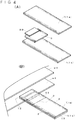
FIG. 2(A) is a perspective view of the closing valve, andFIG. 2(B) is a schematic vertical sectional view of the closing valve. -
FIG. 3(A) is a sectional view taken along line x-x inFIG. 2(B) , andFIG. 3(B) is a schematic vertical sectional view showing an operating state of the closing valve. -
FIG. 4(A) is an exploded perspective view of the closing valve, andFIG. 4(B) is a schematic perspective view showing a process of providing the closing valve ofFIG. 4(A) to a bag. -
FIGS. 5(A) to 5(F) are explanatory views each showing the operation of the closing valve. -
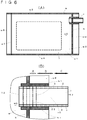
FIG. 6(A) is an overall plan view showing a modification of a sealed bag ofFIG. 1(A) , andFIG. 6(B) is an enlarged plan view showing a modification of a closing valve provided in the sealed bag. -
FIG. 7(A) is a schematic vertical sectional view showing a closing valve according to a second embodiment, andFIG. 7(B) is a schematic vertical sectional view showing a third embodiment. -
FIG. 8(A) is an exploded perspective view of a closing valve according to the third embodiment, andFIG. 8(B) is a plan view showing a state in which the closing valve is attached to a bag after completion. -
FIG. 9(A) is a sectional view of a closing valve according to a fourth embodiment,FIG. 9(B) is a plan view of the closing valve,FIG. 9(C) is a plan view showing a modification of the closing valve,FIG. 9(D) is a plan view showing another modification of the closing valve, andFIG. 9(E) is a sectional view of the same. -
FIGS. 10(A) to 10(E) are perspective views each showing the operation of a conventional closing valve. - Hereinafter, embodiments of the present invention will be described with reference to the drawings.
- In this example, a sealed bag w that includes a closing valve v according to the present invention as a deaerating valve will be described. An overall view (plan view) is illustrated in
FIG. 1(A) , in particular, with a food storage bag provided with the deaerating valve as the sealed bag w.FIG. 1(B) is an enlarged plan view of the closing valve v according to the present invention provided in the sealed bag w ofFIG. 1(A) . - The bag for food is the flexible resin sealed bag w.
- As shown in
FIG. 1(A) , in this example, the sealed bag w is formed by overlapping two sheets of a substantially rectangular upper sheet w1 and lower sheet w2 and sealing three sides w3, w4, and w5 of the rectangle to close. The upper sheet w1 and the lower sheet w2 are sheets formed of a flexible synthetic resin such as polyethylene. The hatched portions inFIGS. 1(A) and 1(B) are a sealed portion h to which the seal is applied. The sealed portion h can be formed by heat sealing. - In the above, a remaining one side w6, which is opened without being closed, is an opening portion (hereinafter, referred to as an opening portion w6 as necessary) of the sealed bag w, and a fastener w7 is provided. As the fastener w7, a well-known one used for closing a synthetic resin bag opening portion may be adopted. For example, in this example, the fastener w7 is composed of concave and convex portions provided over substantially the entire length of one side that is the opening portion w6, and the opening portion is closed by fitting the concave and convex portions together so as to be openable and closable.
- The sealed bag w is not limited to the substantially rectangular one shown in
FIG. 1(A) , and the shape and dimension of the sealed bag w are not particularly limited. For example, it may be implemented as a polygon other than a quadrangle, a circle, or other streamline shape. - The closing valve v, which is the deaerating valve, is provided on one of the three closed sides of the sealed bag w.
- Before the heat sealing of the upper sheet w1 and the lower sheet w2, the heat sealing is performed by sandwiching the closing valve v between the sides of the upper sheet w1 and the lower sheet w2, whereby the closing valve v can be attached to the sealed bag w.
- In this example, the sealed bag w is a deaerating bag in which, for example, food that generates a gas during storage such as coffee or fermented food, clothes or futon bedding whose bulk is reduced by depressurization, or the like is contained in an interior space, that is, a containment space w0, of the sealed bag w. After the heat sealing, this contained item is contained in the containment space w0 through the opening portion w6 by opening the fastener w7.
- In addition to the above, the heat sealing may be performed after the contained item is arranged between the upper sheet w1 and the lower sheet w2 before the heat sealing. In this case, the one side w6 provided with the fastener w7 may also be heat sealed, and the opening portion w6 may be formed in the sealed bag by opening by a user and the opening portion w6 may be closed by the fastener w7 after opened.
- With the sealed portion h as a boundary, the containment space w0 side of the sealed bag w is defined as the inside of the bag, and the outside of the containment space w0 is defined as the outside of the bag.
- The closing valve v is a flexible, flat, substantially cylindrical valve, and uses the interior space of the cylindrical closing valve v as a flow path v0 for fluid (air in this example), thereby allowing movement of fluid between the containment space w0 of the sealed bag w and the outside of the sealed bag w. The closing valve v includes an upstream valve portion a and a downstream valve portion c, which restrict the movement of fluid in the flow path v0 (
FIG. 1(B) ). - In this example in which the closing valve v is a deaerating valve for discharging gas from the inside to the outside of the sealed bag w, the flow path is defined such that the inside of the bag is the upstream side and the outside of the bag is the downstream side. The upstream valve portion a is arranged upstream with respect to the downstream valve portion c. A portion of the closing valve v between the upstream valve portion a on the upstream side and the downstream valve portion c on the downstream side composes a buffer portion b for retaining fluid. In particular, the upstream valve portion a is provided at a pressure difference position between an internal pressure and an external pressure of the sealed bag w. The pressure difference position is, in this example, a position where the closing valve v is mounted in the sealed bag w, and coincides with the sealed portion h.
- Specifically, the closing valve v is formed by overlapping two sheets of flexible, synthetic
resin exterior films 1 such as polyethylene. - Hereinafter, if necessary, the
exterior film 1 arranged above inFIGS. 2(A) and 2(B) is referred to as an upper exterior film la, and theexterior film 1 arranged below the upper exterior film la is referred to as a lowerexterior film 1b. - As shown in
FIGS. 1(B) and2(A) , the both sides of the exterior films la and 1b, which are overlapped and face each other, are closedportions 2 that are closed. In this example, theclosed portion 2 is a portion that is sealed as a side seal (hereinafter referred to as a side seal portion 2). Theside seal portion 2 may be formed by well-known means such as heat sealing. With the formation of theside seal portion 2, the overlappedexterior film 1 is formed into a flat cylindrical shape with both ends open. A fluid passage (the flow path v0) is formed between the upper exterior film la and the lowerexterior film 1b. With respect to the openings at both ends of theexterior film 1, when the closing valve v is attached to the sealed bag w, one end side of theexterior film 1 serves as aninflow portion 12 that opens to the inside of the sealed bag w, and the other end side of theexterior film 1 serves as anoutflow portion 13 that opens to the outside of the sealed bag w. - In the present invention, upstream and downstream and inflow and outflow are each based on a flow direction of a forward flow in which the closing valve allows a fluid to pass through unless otherwise noted, and in a case where they are based on a flow direction of a reverse flow in a direction reverse to the flow direction of the forward flow, the same is clearly indicated.
- The upstream valve portion a is positioned in a region including the sealed portion h defining the inside of the sealed bag w from the outside thereof, which is the pressure difference position in the flow path v0 as described above.
- The upstream valve portion a is a check valve that allows movement of a fluid from the upstream side to the downstream side of the flow path v0, that is, the forward flow, and restricts movement of the fluid from the downstream side to the upstream side, that is, the reverse flow. As shown in
FIG. 2(B) , the upstream valve portion a includes a valve body film made of synthetic resin such as polyethylene. Hereinafter, the valve body film of the upstream valve portion a is referred to as anupstream valve film 3 where necessary. - The
upstream valve film 3 is arranged between the upperexterior film 1a and the lowerexterior film 1b, and the upper surface of theupstream valve film 3 is not fixed to the upperexterior film 1a but is released on the upstream side and the downstream side thereof. The lower surface of theupstream valve film 3 is fixed to the lowerexterior film 1b in a sealed state on the upstream side thereof, and is released on the downstream side thereof. - More specifically, the
upstream valve film 3 has aflap portion 31 that performs open/close operations of the valve and a fixingportion 32 that fixes theflap portion 31 to the lowerexterior film 1b. - The
upstream valve film 3 moves up and down in response to pressure fluctuations in the flow path v0, and the upper surface of the upstream valve film 3 (flap portion 31) comes into close contact with the lower surface of the upperexterior film 1a to block the flow path v0, and the upper surface of the upstream valve film 3 (flap portion 31) is opened from the lower surface of the upperexterior film 1a to open the flow path v0. - As shown in
FIG. 4(A) , by forming theside seal portion 2 by sandwiching theupstream valve film 3 between the upper and lowerexterior films side seal portion 2 is formed, theupstream valve film 3 can be attached between theexterior films 1 together with the adhesion between the upper and lowerexterior films FIG. 4(A) , the region where the spots are marked is a portion to be adhered by theside seal portion 2. - A
non-welding film 33 to be described later is provided on theupstream valve film 3 before theupstream valve film 3 is attached between the upper and lowerexterior films 1. - When the upper sheet w1 and the lower sheet w2 are heat sealed as described above at the time of forming the sealed bag w, the upper
exterior film 1a, theupstream valve film 3, and the lowerexterior film 1b, which are integrated at theside seal portion 2, are inserted (FIG. 4(B) ) between the upper sheet w1 and the lower sheet w2, and performing the heat sealing enables the sealed bag w to be formed, the upstream valve portion a to be formed on the closing valve v, and the closing valve v to be attached to the sealed bag w simultaneously (FIG. 2(A) ). That is, the fixingportion 32 of theupstream valve film 3 is formed by the heat sealing of the sealed portion h. Therefore, in theupstream valve film 3, the fixingportion 32 indicates the pressure difference position. - In the state before attachment to the sealed bag w, the fixing
portion 32 is not formed, and theupstream valve film 3 is only fixed to the upper and lowerexterior films 1 at theside seal portion 2. - When the sealed portion h of the sealed bag w is formed, the fixing
portion 32 is formed by the heat sealing. At that time, thenon-welding film 33 is arranged on the upper surface of theupstream valve film 3 so that the upper surface of theupstream valve film 3 opposite to the fixingportion 32 is not welded to the upperexterior film 1a by heat sealing of the sealed portion h (FIGS. 1(B) ,2 ,3 , and4 ). - The
non-welding film 33 is a film that is not heat-welded at the heat sealing temperature of the sealed portion h, and prevents welding with the upperexterior film 1a. Thenon-welding film 33 itself is fixed to theupstream valve film 3 via a welding film 34 (FIG. 3(B) ), which is heat-welded. The welding film 34 is overlapped on thenon-welding film 33 by lamination. As a method of lamination, a well-known method other than heat sealing such as using an adhesive is employed. - Instead of the
non-welding film 33, a heat-resistant ink can be applied. - As shown by alternate long and short dash line in
FIG. 1(B) , thenon-welding film 33 is provided on theupstream valve film 3 within a range not overlapping theside seal portion 2 so as not to block the sealing by theside seal portion 2. In this example, thenon-welding film 33 has a width substantially equal to the distance between the side seal portions 2 (FIGS. 1(B) and3(A) ). However, as long as the sealing by theside seal portion 2 is not blocked, thenon-welding film 33 that overlaps theside seal portion 2 is not excluded. - As shown in
FIG. 6(B) , even if thenon-welding film 33 overlaps theside seal portion 2 and the sealing by theside seal portion 2 is interrupted, the side of theexterior film 1 may be closed by providing an extension portion w8 extending to the outside of the sealed portion h with respect to the side w5 to which the closing valve v of the sealed bag w is attached, and by providing an auxiliary sealed portion h1 crossing the sealed portion h, coming into contact with theside seal portion 2, and extending parallel to the side seal portion. As shown inFIGS. 6(A) and 6(B) , the auxiliary sealed portion h1 is provided from the inside of the sealed bag w to the extension portion w8. The auxiliary sealed portion h1 can be formed on the upper sheet w1 and the lower sheet w2 by heat sealing when the sealed bag w is formed together with the sealed portion h. - The upper and lower
exterior films 1 and theupstream valve film 3 may be formed of a single synthetic resin film such as polyethylene or a laminate, and a surface (i.e., the lower surface of the upperexterior film 1a, the upper surface of the lowerexterior film 1b, and the upper surface of the upstream valve film 3) composing the inner surface of the flow path v0 is preferably a self-adhesive surface. The film including the self-adhesive surface on one side may be a coextrusion die obtained by coextruding a film base material such as polyethylene and a self-adhesive thermoplastic resin such as ethylene vinyl acetate copolymer resin (EVA), or a coating die obtained by coating a film base material such as polyethylene with an adhesive. - The upstream valve portion a is implemented as a check valve that includes the
upstream valve film 3 described above, and as shown inFIG. 3(B) , the upper surface of theflap portion 31 of theupstream valve film 3 comes into close contact with the lower surface of the opposing upperexterior film 1a, and the closing valve v is brought into a valve closed state. - For the purpose of preventing the valve opening operation from being impeded by the adhesion of the
upstream valve film 3 to the upper surface of the lowerexterior film 1b to which theupstream valve film 3 is fixed, as shown inFIG. 3(B) , theflap portion 31 can be provided on the lower surface thereof with a hardly pressure-sensitive adhesion part 35 on the surface facing the exterior film 1 (lowerexterior film 1b) (FIG. 3(B) ), but may be provided without the hardly pressure-sensitive adhesion part 35. - The above-described embodiment can be said to be a conventional closing valve (check valve), but a feature of the closing valve of the present invention is that, as shown in
FIG. 2(B) , a valve portion includes at least two valve portions, that is, the upstream valve portion a and the downstream valve portion c, which is positioned downstream with respect to the upstream valve portion, and the buffer portion b for retaining the fluid in the flow path v0 is provided in the upstream valve portion a and the downstream valve portion c. - In the buffer portion b, the upper and lower
exterior films 1 directly face each other, and the surface (i.e., the lower surface of the upperexterior film 1a and the upper surface of the lowerexterior film 1b) composing the inner surface of the flow path v0 is a self-adhesive surface as described above, and one or both of theexterior films 1 are provided with a hardly pressure-sensitive adhesion portion 4. The hardly pressure-sensitive adhesion portion 4 is made to be of hardly adhesive property as compared to a case where the self-adhesive surfaces face each other. The hardly pressure-sensitive adhesion portion 4 does not have adhesiveness and prevents the twoexterior films 1 from coming into close contact. - As shown in
FIGS. 2(B) and3(A) , in this example, the hardly pressure-sensitive adhesion portion 4 is provided on the lower surface of the upperexterior film 1a, but may be provided on the upper surface of the lowerexterior film 1b, or may be provided on both the upperexterior film 1a and the lowerexterior film 1b. Thus, as the internal pressure in the buffer portion b increases, the buffer portion b provides an inflated space in which fluid is retained. - The hardly pressure-
sensitive adhesion portion 4 can be formed by using well-known ink that reduces the self-adhesiveness of theexterior film 1 to coat the ink on theexterior film 1. However, it is also possible to form the hardly pressure-sensitive adhesion portion 4 by other means such as arranging another film other than the ink. InFIG. 2(B) , in order to make the arrangement of the hardly pressure-sensitive adhesion portion 4 easy to understand, the thickness of the hardly pressure-sensitive adhesion portion 4 is emphasized to be larger than that of the other components. - The downstream valve portion c does not include a valve body film in this example. In the downstream valve portion c, the
exterior film 1 does not include the hardly pressure-sensitive adhesion portion 4 such as the buffer portion b. Therefore, in the downstream valve portion c, the lower surface of the self-adhesive upperexterior film 1a and the upper surface of the self-adhesive lowerexterior film 1b directly face each other, and they come into close contact with each other as anadhesive portion 5 to close the gap between the upper and lower exterior films 1 (FIG. 3(B) ). - By the close contact, the downstream valve portion c limits the reverse flow as well as the forward flow of fluid. The downstream valve portion c is opened by receiving pressure from a fluid. Therefore, unless the internal pressure of the flow path v0 in the buffer portion b becomes higher than that of the downstream side of the downstream valve portion c, the downstream valve portion c maintains the valve closed state by the self-adhesion. In this example, since the fluid is a gas, the downstream valve portion c is closed unless the internal pressure of the buffer portion b becomes higher than the external pressure.
- The closedness of the flow path depends on the thickness, flexibility, shape, and the like of the vertically opposed films composing the flow path v0, and the largest factors that influence the closedness include two factors of the adhesiveness and the width of the flow path.
- The adhesiveness, which is the first factor, is about the level of adhesiveness of the vertically opposed films composing the flow path v0, and the higher the adhesiveness is, the higher the closedness of the flow path is, and the lower the adhesiveness is, the lower the closedness of the flow path is. Adhesiveness can be measured by the T-type peel strength test, but it can also be measured by the opening test of the cylindrical body (a test in which a cylindrical body is produced by vertically opposed films, and after these films are held in a predetermined range by a predetermined force and brought into close contact, a fluid is introduced from one end of the cylindrical body, and the pressure of the fluid when the fluid comes out from the other end is measured).
- The width of the flow path, which is the second factor, is about the length of the width of the flow path (i.e., the distance in the direction orthogonal to the flow direction of the fluid in the flow path v0), and when the adhesiveness is the same, the smaller the width of the flow path is, the higher the closedness of the flow path is.
- The operation of the closing valve v will be briefly described with reference to
FIG. 5 . Here, the details of the structure of each valve portion will be omitted and only the operation will be described. Here, the upstream side refers to the upstream side with respect to the buffer portion b in the fluid flow path v0, and the downstream side refers to the downstream side with respect to the buffer portion b in the fluid flow path v0. - As shown in
FIG. 5(A) , in a state where the pressure is balanced between the inside and outside of the sealed bag w in the initial stage of use, there is no movement of fluid in the flow path v0, both the upstream valve portion a and the downstream valve portion c are closed, and the buffer portion b is also contracted to narrow the width between the twoexterior films 1. - When the pressure on the upstream side increases and in the internal pressure, a relation of the upstream side > the buffer portion b = the downstream side is satisfied, for example, the increase ratio of the internal pressure of a:b:c becomes +1:0:0 (atmospheric pressure), the upstream valve portion a on the upstream side opens as shown in
FIG. 5(B) . As shown inFIG. 5(C) , a fluid flows into the buffer portion b due to the opening of the upstream valve portion a, and the buffer portion b is inflated in the valve closed state of the downstream valve portion c. Since the buffer portion b is arranged in a bag outside section of the flow path v0, the buffer portion b can be inflated relatively freely without being affected by the internal pressure of the sealed bag w as in a bag inside section from the surface side of theexterior film 1, and can sufficiently perform the function of retaining the fluid as a buffer. - The internal pressure of the buffer portion b increases, and in the internal pressure of the flow path v0, via a state of the upstream side ≧ the buffer portion b ≧ the downstream side, a relation of the upstream side = the buffer portion b > the downstream side is satisfied, for example, the increase ratio of the internal pressure of a:b:c becomes +1:+1:0, and as shown in
FIG. 5(D) , the downstream valve portion c as well as the upstream valve portion a is opened to start deaeration. - When the pressure on the upstream side is reduced due to deaeration, as shown in
FIG. 5(E) , the upstream valve portion a is closed in a state where the downstream valve portion c is opened, and the internal pressures of the upstream side and the buffer portion b are shifted to a balanced state. That is, the internal pressure goes through a state of the upstream side ≦ the buffer portion b > the downstream side, for example, a state of the increase ratio of the internal pressure of +0.5:+1:0, and then shifts to a state of the upstream side = the buffer portion b ≥ the downstream side, for example, a state of the increase ratio of the internal pressure of 0(-1):+0.5:0. Finally, the internal pressure of the buffer portion b and that of the downstream side are balanced. That is, as shown inFIG. 5(F) , the internal pressure shifts to a state of the upstream side = the buffer portion b = the downstream side or the upstream side ≦ the buffer portion b = the downstream side, for example, the increase ratio of the internal pressure of 0(-1):0:0. - In any of the balanced states shown in
FIGS. 5(E) and 5(F) , since the pressure difference between the bag inside section and the bag outside section bounded by the upstream valve portion a is larger than the balanced state in the conventional case shown inFIG. 10(E) , it is also easier to block the flow path v0 as compared to the conventional case shown inFIG. 10 . - Note that, when the upstream side and the buffer portion b are balanced shown in
FIG. 5(E) , there is a possibility that a slight reverse flow occurs from the buffer portion b to the upstream side, but the fluid in the buffer portion b is a fluid that has been on the upstream side from the buffer portion until it is retained in the buffer portion. Therefore, there is no problem that a fluid from the outside of the bag enters. - Next, in the balanced state between the buffer portion b and the downstream side from the buffer portion shown in
FIG. 5(F) , there is a possibility that the fluid on the downstream side (atmosphere in the case of deaerating bags) slightly flows back toward the buffer portion, but at this time, the upstream valve portion a is closed to close the flow path, and hence the reverse flow to the inside of the bag hardly occurs. - In the next operation, that is, when the downstream valve portion is opened, the fluid entering the buffer portion from the downstream side of the buffer portion is discharged to the downstream side of the buffer portion again, and the fluid in the upstream side with respect to the buffer portion is filled in the buffer portion.
- Therefore, in any of the above balanced states, the reverse flow of the external fluid into the bag can be suppressed.
- Particularly, in the bag according to the present invention, since the buffer portion is arranged in the bag outside section in the flow path, the cylindrical closing valve can expand and contract without being affected by the internal pressure of the bag. Therefore, in the present invention, the above effect can be exerted more remarkably.
- In order for the buffer portion b to effectively exert its function, it is necessary to configure the buffer portion b to be inflated by the fluid during forward flow (upon exiting through the flow path v0 from the containment space w0).
- Therefore, as the first means, the buffer portion b needs to be configured in such a manner that the closedness of the flow path is lower than that of the downstream valve portion c, and more preferably, the closedness of the flow path is lower than that of both the upstream valve portion a and the downstream valve portion c.
- In the first embodiment, since the upstream valve portion a, the buffer portion b, and the downstream valve portion c have the same width of the flow path v0, the closedness is determined by the adhesiveness.
- In this embodiment, the upstream valve portion a and the downstream valve portion c have the equal closedness, and the closedness of the buffer portion b having the hardly pressure-
sensitive adhesion portion 4 is lower than that of both of the valve portions a and c. - When the upstream valve portion a, the buffer portion b, and the downstream valve portion c have the equal adhesiveness by not providing the buffer portion b with the hardly pressure-
sensitive adhesion portion 4, the width of the flow path v0 of the buffer portion b can be made wider than that of the downstream valve portion c, and more preferably, it can be made wider than that of both of the upstream valve portion a and the downstream valve portion c. - As the second means, when the fluid flows out (when the upstream valve portion a is opened due to an increase in the internal pressure of the containment space w0), if the downstream valve portion c is also opened immediately after the fluid is introduced into the buffer portion b, the buffer portion b may not be inflated by the fluid, and hence measures for preventing this is taken.
- As the second means, in this embodiment, a sufficient length is given to the buffer portion b.
- Specifically, in the buffer portion b, the length of the fluid in the flow direction of the flow path v0 is longer than that of at least one of the upstream valve portion a and the downstream valve portion c, and more desirably, the length of the fluid in the flow direction of the flow path v0 is longer than that of both of the upstream valve portion a and the downstream valve portion c.
- As shown in
FIG. 2(B) , the length of the upstream valve portion a and the downstream valve portion c indicates the length of a portion functioning as a valve portion to close the flow path, and the length of the upstream valve portion a is the length of a region of theflap portion 31 downstream with respect to the fixingportion 32 and a region not overlapping the hardly pressure-sensitive adhesion portion 4. The length of the buffer portion b is the length of a region where the hardly pressure-sensitive adhesion portion 4 is provided. The length of the downstream valve portion c is the length of a region where theadhesive portion 5 is provided downstream with respect to the hardly pressure-sensitive adhesion portion 4. - In this embodiment, in the buffer portion b, the length of the fluid in the flow direction of the flow path v0 is longer than that of both of the upstream valve portion a and the downstream valve portion c.
- The space between the
upstream valve film 3 and the lowerexterior film 1b overlapped the lower surface of theupstream valve film 3 is sealed by the fixingportion 32 on the upstream side thereof, and is conducted to the buffer portion b on the downstream side thereof. As a result, some of the fluid having entered the buffer portion b may be introduced into the space between theupstream valve film 3 and the lowerexterior film 1b as shown inFIG. 3(B) , and this space will be described as a buffer continuous portion d in the following description. - As shown in
FIG. 7(A) , the downstream valve portion c may be provided with a valve body film, similarly to the upstream valve portion a. Specifically, in the downstream valve portion c, adownstream valve film 6 is fixed to one of theexterior films 1 as the valve body film. Thedownstream valve film 6 includes a sub flap portion 61 and asub fixing portion 62 having the same functions as theflap portion 31 and the fixingportion 32. That is, in the downstream valve portion c, thedownstream valve film 6 is fixed to the upper surface of the lowerexterior film 1b by thesub fixing portion 62. The sub flap portion 61 extends toward the downstream side from thesub fixing portion 62. - The sub flap portion 61 is provided with a sub non-welding film 63 similar to the
non-welding film 33. - The
sub fixing portion 62 is heat-sealed by a well-known heat sealing device from the surface side of one exterior film 1 (in this example, the lowerexterior film 1b) to which thedownstream valve film 6 is attached at the time of manufacturing the closing valve v before attaching it to the sealed bag w, so that thesub fixing portion 62 crossing the rectangular sub flap portion 61 in a plan view can be formed (FIG. 8(B) , which is referred to in a third embodiment, shows a state in which the sub flap portion 61 is viewed in a plan view). - Also in the second embodiment shown in
FIG. 7(A) , the lower surface of the upperexterior film 1a and the upper surface of the lowerexterior film 1b, which compose the inner surface of the flow path v0, have the self-adhesiveness described above as theadhesive portion 5. On the other hand, the opposing surfaces (more specifically, the upper surface of the upperexterior film 1a and the lower surface of the lowerexterior film 1b) may not have the self-adhesiveness. - Similarly to the
upstream valve film 3, the upper surface of thedownstream valve film 6 has the self-adhesiveness. On the other hand, the opposing surfaces (more specifically, the lower surface of thedownstream valve film 6 and that of the upstream valve film 3) may not have the self-adhesiveness. - Matters not specifically mentioned in the second embodiment are the same as those in the first embodiment.
- In this example, as shown in
FIGS. 7(B) ,8(A), and 8(B) , each of theexterior films 1 is composed of afirst composition film 10 and asecond composition film 11, which are formed separately from each other. - That is, the upper
exterior film 1a is composed of two films, which are an upper first composition film 10a and an upper second composition film 11a, and the lowerexterior film 1b is composed of a lower first composition film 10b and a lower second composition film 11b. The upper first composition film 10a and the lower first composition film 10b are overlapped to form a flat cylinder whose side portions are sealed by theside seal portion 20. The upper second composition film 11a and a lower second composition film 11b are also overlapped to form a flat cylinder whose side portions are sealed by a sub side seal portion 21 (FIG. 8(B) ). InFIG. 8(A) showing a state in which the closing valve v is disassembled, a dark (dense) spot indicates a region to be referred to as theside seal portion 20, and a thin (sparse) spot indicates a region to be referred to as the subside seal portion 21. - The cylinder composed by the
second composition film 11 has a larger cylinder diameter than that of the cylinder composed by thefirst composition film 10. As shown inFIG. 8(B) , the width across the flow path v0 of thesecond composition film 11 is larger than that of thefirst composition film 10. - Apart of the flow path v0 is provided between the upper first composition film 10a and the lower first composition film 10b, and another part of the flow path v0 is also provided between the upper second composition film 11a and the lower second composition film 11b.
- That is, each of the
second composition films 11 is indirectly via a part of the sealed bag w or directly connected to each of thefirst composition films 10 at the pressure difference position to provide another part of the flow path v0 extending from thefirst composition film 10 toward the outside of the bag. In this example, thesecond composition film 11 is fixed to the sealed bag w by the sealed portion h and is indirectly connected to the first composition film 10 (FIGS. 7(B) and8(B) ). However, thesecond composition film 11 can be fixed directly to thefirst composition film 10. - Each of the
second composition films 11 is arranged on the outside of the bag, and the flow path v0 provided is defined as a section on the outside of the bag. - As shown in
FIGS. 7(B) and8(B) , the upper first composition film 10a and thenon-welding film 33 on the lower first composition film 10b provide theinflow portion 12, and the upper and lowersecond composition films outflow portion 13. The upper and lowerfirst composition films second composition films upstream valve film 3 is arranged above and fixed to one of the first composition films 10 (the lower first composition film 10b). Thedownstream valve film 6 is arranged above and fixed to one of the second composition films 11 (the lower second composition film 11b). - In this example, the downstream valve portion c includes the
downstream valve film 6 as described above. However, similarly to the first embodiment, the downstream valve portion c may not include thedownstream valve film 6. - In this embodiment, the region of the hardly pressure-
sensitive adhesion portion 4 between a tip end of the interior portion 14 and thedownstream valve film 6 is defined as the buffer portion b. - As shown in
FIG. 7(B) , the space between the upper surface of the upper first composition film 10a of the interior portion 14 and the lower surface of the upper second composition film 11a facing the upper surface of the upper first composition film 10a, and the space between the lower surface of the lower first composition film 10b of the interior portion 14 and the upper surface of the lower second composition film 11b compose the buffer continuous portion d. The buffer continuous portion d is conducted to the buffer portion b, and a part of the fluid flows into the buffer continuous portion d. - In the example of
FIG. 7(B) , the self-adhesiveness of the lower surface of the upper first composition film 10a is greater than the self-adhesiveness of the upper surface of the upper first composition film 10a. The upper surface of the lower second composition film 11b does not have the self-adhesiveness. The self-adhesiveness of the upper surface of the upper first composition film 10a is smaller than the self-adhesiveness of the lower surface of the upper first composition film 10a, but is larger than the self-adhesiveness of the upper surface of the lower second composition film 11b. Therefore, relatively, if the self-adhesiveness of the lower surface of the upper first composition film 10a is large, the self-adhesiveness of the upper surface of the upper first composition film 10a is moderate, and the self-adhesiveness of the upper surface of the lower second composition film 11b is small. As described above with respect to self-adhesiveness, at least a surface of theupstream valve film 3 opposite to thenon-welding film 33 has a moderate self-adhesiveness. In the interior portion 14, the lower surface of the lower first composition film 10b also has a moderate self-adhesiveness. The self-adhesiveness of the upper surface of the lower first composition film 10b is large. - The self-adhesiveness of the
downstream valve film 6 in the third embodiment is the same as that described in the second embodiment. - In addition, matters not specifically mentioned in the third embodiment are the same as those in the first and second embodiments.
- A fourth embodiment will be described with reference to
FIG. 9 . -
FIG. 9(A) is a sectional view of the closing valve according to the fourth embodiment, andFIG. 9(B) is a plan view of the same. - The closing valve is a modification of the first embodiment, only the main differences are described, and the closing valve is substantially the same as that of the first embodiment in that the same reference numerals are given and no description is given.
- First, the
inflow portion 12 in this example has a structure in that the containment space w0 of the bag w is opened in a planar shape. The upperexterior film 1a is elongated inside the containment space w0, and afilter 51 such as a nonwoven fabric is arranged therebelow. The upperexterior film 1a and thefilter 51 inside the containment space w0 have substantially the same size and shape, and the periphery thereof is fixed by the heat seal of afilter fixing portion 52. The fluid inside the containment space w0 is introduced into the flow path v0 through thefilter 51, whereby fine powder and the like can be prevented from being introduced into the closing valve or flowing out to the outside. - In this example, the
upstream valve film 3 is fixed by thefilter fixing portion 52 with thefilter 51 positioned outside the bag w from the position of the sealed portion h, and thefilter fixing portion 52 serves also as the fixingportion 32. Theupstream valve film 3 has theflap portion 31 on the downstream side of thefilter fixing portion 52 and the fixingportion 32. Theupstream valve film 3, together with the upper and lowerexterior films - Regardless of the manufacturing process, this structure allows the closing valve v in a state where the
upstream valve film 3 is fixed by thefilter fixing portion 52 with thefilter 51 to be inserted between the upper sheet w1 and the lower sheet w2 of the bag w to be heat-sealed. One of thefilter fixing portion 52 and the sealed portion h may be located outside the other, or thefilter fixing portion 52 and the sealed portion h may be located at the same position. However, if thefilter fixing portion 52 and the sealed portion h are located at the same position, the heat sealing property may be lowered, and hence it is preferable to make the seal positions different. - In this example, since the
filter fixing portion 52 is positioned outside the bag w with respect to the position of the sealed portion h, the upstream valve portion a is positioned downstream with respect to the heat seal of thefilter fixing portion 52. - Note that the structure of the
inflow portion 12 can also be adopted in each of the above-described embodiments. - Next, in this example, in the buffer portion b, the exterior film 1 (the upper
exterior film 1a and the lowerexterior film 1b) does not include the hardly pressure-sensitive adhesion portion 4, and both the lower surface of the upperexterior film 1a with self-adhesiveness and the upper surface of the lowerexterior film 1b with self-adhesiveness directly face each other and they make close contact each other as theadhesive portion 5. Therefore, there is no difference between the buffer portion b and the downstream valve portion c in that the buffer portion b and the downstream valve portion c close between the upper and lowerexterior films 1. - In other words, the buffer portion b and the downstream valve portion c are common in that they compose a tip space between the downstream end of the
upstream valve film 3, which is a valve body film, and the downstream end of the exterior film 1 (the upperexterior film 1a and the lowerexterior film 1b). - This tip space is divided, depending on the level of closedness, into a highly closed space composing the downstream valve portion c and a lowly closed space composing the buffer portion b. Specifically, the downstream valve portion c is a portion having the smallest width of the flow path v0 without the valve body film, and the buffer portion b is a portion having a larger width of the flow path v0 than that of the highly closed space composing the downstream valve portion c. In this example, as shown in
FIG. 9(B) , a downstreamvalve point seal 53 is provided at the center of the flow path v0, thereby narrowing the width of the flow path and enhancing the closedness. - More specifically, as described above, the closedness of the flow path depends on the thickness, flexibility, shape, and the like of the vertically opposed films composing the flow path v0, and the largest factors that influence the closedness include two factors, namely, the adhesiveness and the width of the flow path.
- As for the adhesiveness, which is the first factor, the buffer portion b and the downstream valve portion c have the same adhesiveness.
- As for the width of the flow path, which is the second factor, since the width of the flow path (i.e., the distance in the direction orthogonal to the flow direction of the fluid in the flow path v0) is smaller in the downstream valve portion c than in the buffer portion b, the closedness of the flow path is high.
- The
upstream valve film 3 has the equal adhesiveness to that of the buffer portion b and the downstream valve portion c in terms that the upper surface of theupstream valve film 3 has self-adhesiveness and faces the lower surface of the upperexterior film 1a. As in the buffer portion b, the width of the flow path is larger than that of the downstream valve portion c. Therefore, the closedness of the flow path is the highest in the downstream valve portion c, and the upstream valve portion a and the buffer portion b are substantially equal to each other. - As described above, in order for the buffer portion b to effectively exert its function, it is necessary to configure the buffer portion b to be inflated by the fluid during forward flow (upon exiting through the flow path v0 from the containment space w0).
- Therefore, as the first means, the buffer portion b needs to be configured in such a manner that the closedness of the flow path is lower than that of the downstream valve portion c, and more preferably, the closedness of the flow path is lower than that of both the upstream valve portion a and the downstream valve portion c.
- As the second means, when the fluid flows out (when the upstream valve portion a is opened due to an increase in the internal pressure of the containment space w0), if the downstream valve portion c is also opened immediately after the fluid is introduced into the buffer portion b, the buffer portion b may not be inflated by the fluid, and hence it is necessary to take measures to prevent this.
- As specific means for satisfying the second means, in this embodiment, the closedness of the downstream valve portion c is made higher than that of the upstream valve portion a.
- If these two means are brought together, the closedness of the downstream valve portion c is configured to be higher than that of both of the upstream valve portion a and the buffer portion b, and in this embodiment, the width of the flow path is minimized by providing the downstream
valve point seal 53. - Thus, under the condition where the pressure difference is relatively small, even if the internal pressure of the bag w increases to the fluid pressure at which both the upstream valve portion a and the buffer portion b open, the highly closed downstream valve portion c does not open. Thus, even when the length of the buffer portion b is short, the fluid stops and inflates in the buffer portion b. A part of the fluid having entered the buffer portion b also flows into the buffer continuous portion d between the
upstream valve film 3 and the lowerexterior film 1b. - The lengths of the flow path v0 of the buffer portion b and the downstream valve portion c in the flow direction can be set on a condition of exerting the operation described above, and it is appropriate that each of them is set to a length of at least 2 mm and more preferably, a length of at least 3 mm or more.
- As shown in
FIG. 9(C) , a plurality of downstream valve point seals 53 may be provided, for example, on the left and right sides. - As shown in
FIGS. 9(D) and 9(E) , an upstreamvalve point seal 54 may be provided between theupstream valve film 3 and the upperexterior film 1a, where the closedness needs to be made higher in the downstream valve portion c. Specifically, it is necessary to make the flow path width narrower in the downstream valve portion c by increasing the number or width of the downstream valve point seals 53. - As described above, in this embodiment, the closedness of the flow path is realized only by the flow path width, but it is also possible to realize the closedness by the adhesiveness as shown in the above embodiments, or it is also possible to use both in combination.
- The upstream valve portion a may be composed of a pair of opposed
upstream valve films 3. That is, theupstream valve film 3 may be provided also on theexterior film 1 opposed to theexterior film 1 provided with theupstream valve film 3, and thus the upstream valve portion a is closed by the close contact of theflap portions 31 of both of theupstream valve films 3, and the upstream valve portion a is opened by the separation of the flap portions. Also in the case where the downstream valve portion c includes a valve body film, the downstream valve portion c may be provided with a pair of opposing valve body films (the downstream valve films 6), unlike those shown inFIGS. 7(A) and 7(B) . - The number of the valve portions is not limited to two portions of the upstream valve portion a and the downstream valve portion c, and it is also possible to provide three or more valves on the condition that a space in which the fluid is retained between flowing in the flow path v0 from the upstream valve portion a and flowing out from the downstream valve portion c is generated.
- Although each of the above embodiments has been described by presenting an example of the deaerating valve of a sealed bag for food, the bag w of the present invention is not limited to a deaerating bag for discharging a gas, and discharge of something other than a gas such as a liquid may be performed by the closing valve v. In addition, the closing valve v according to the present invention may be implemented as the closing valve v for preventing the reverse flow of the fluid when the fluid is discharged from the sealed bag w to the outside of the bag, or for preventing the reverse flow when the fluid is injected from the outside of the bag into the bag.
- The position where the closing valve v is arranged is not limited to the end of the bag w, but may be a central part. For example, it may be provided at the position of the back seal of a pillow package, or a hole may be made in one sheet instead of between two sheets, and the whole circumference of the
filter 51 shown inFIG. 9 may be sealed to the sheet by heat sealing or the like. - The sealed portion h of the sealed bag w may be formed by another well-known means such as use of not only heat sealing but also an adhesive. The
side seal portion 2 of the closing valve v may be formed not only by heat sealing but also by an adhesive. Attachment of each valve body film can be carried out not only by heat sealing but also by an adhesive. When an adhesive is used, thenon-welding film 33 and the sub non-welding film 63 can be omitted. - As described above, coffee, fermented food, futon bedding, and clothes have been exemplified as the contained items of the sealed bag w. As long as the sealed bag w can be used as the deaerating bag, an object other than those exemplified can be contained as a contained item. The above fermented food is not limited to a typical fermented food such as miso (fermented soybean paste), koji (malted rice), and pickles. Examples of use for other than food include, as described above, use of the sealed bag as a storage bag for storing futon bedding or clothes. This storage bag can reduce the volume by removing air inside the bag from the closing valve v, which is a deaerating valve, after storing futon bedding or clothes as a compression bag.
- The sealed bag may be used, for example, as a cushioning material to be used as an air cushion where air is injected, in addition to containing an object to be contained as a contained item.
- The closing valve v is not limited to one composed of the exterior film and the valve body film, and may be shaped into a form other than the film. For example, the sealed bag may be a toy that is inflated by injecting air when used such as a beach ball, an inner tube, a doll, and the like, and the closing valve v may be a cylindrical rubber or plastic molded article provided in the air inlet of the toy.
- The above-described embodiments and the above-described modifications are merely examples of embodiments of the present invention, and other embodiments are not excluded as long as the configuration described in the claims of the present invention is adopted.
-
- a
- upstream valve portion
- b
- buffer portion
- c
- downstream valve portion
- d
- buffer continuous portion
- f, w
- bag
- h
- sealed portion
- h1
- auxiliary sealed portion
- v
- closing valve
- v0
- flow path
- w
- sealed bag
- w0
- containment space
- w1
- upper sheet
- w2
- lower sheet
- w6
- opening portion
- w7
- fastener
- w8
- extension portion
- 1, 1a, 1b
- exterior film
- 1a
- upper exterior film
- 1b
- lower exterior film
- 2
- closed portion
- 2, 20
- side seal portion
- 3
- upstream valve film
- 4
- hardly pressure-sensitive adhesion portion
- 5
- adhesive portion
- 6
- downstream valve film
- 10, 10a, 10b
- first composition film
- 11, 11a, 11b
- second composition film
- 12
- inflow portion
- 13
- outflow portion
- 14
- interior portion
- 21
- sub side seal portion
- 31
- flap portion
- 32
- fixing portion
- 33
- non-welding film
- 34
- welding film
- 35
- hardly pressure-sensitive adhesion part
- 51
- filter
- 52
- filter fixing portion
- 53
- downstream valve point seal
- 54
- upstream valve point seal
- 61
- sub flap portion
- 62
- sub fixing portion
- 63
- sub non-welding film
Claims (9)
- A closing valve having a flexible and substantially cylindrical shape and made of a sheet, in which: exterior films are arranged above and below in an outside and both sides of each of the exterior films are closed to form closed portions; one end side serves as an inflow portion to a forward flow, and the other end side serves as an outflow portion to the forward flow; a flow path for the forward flow and a reverse flow flowing in an opposite direction of the forward flow is composed; and the flow path includes a valve portion that restricts movement of a fluid in the flow path, wherein:the valve portion includes at least two valve portions that are an upstream valve portion that is positioned upstream of the forward flow and a downstream valve portion that is positioned downstream of the forward flow with respect to the upstream valve portion;a buffer portion for retaining a fluid in the flow path is composed between the upstream valve portion and the downstream valve portion;closedness of the flow path in the buffer portion is lower than closedness of the downstream valve portion; andclosedness of the flow path in the upstream valve portion is lower than the closedness of the downstream valve portion.
- A closing valve having a flexible and substantially cylindrical shape and made of a sheet, in which: exterior films are arranged above and below in an outside and both sides of each of the exterior films are closed to form closed portions; one end side serves as an inflow portion to a forward flow, and the other end side serves as an outflow portion to the forward flow; a flow path for the forward flow and a reverse flow flowing in an opposite direction of the forward flow is composed; and the flow path includes a valve portion that restricts movement of a fluid in the flow path, wherein:the valve portion includes at least two valve portions that are an upstream valve portion that is positioned upstream of the forward flow and a downstream valve portion that is positioned downstream of the forward flow with respect to the upstream valve portion;a buffer portion for retaining a fluid in the flow path is composed between the upstream valve portion and the downstream valve portion;closedness of the flow path in the buffer portion is lower than closedness of the downstream valve portion; anda length in a flow direction of the fluid in the flow path in the buffer portion is longer than a length of at least any one of the upstream valve portion and the downstream valve portion.
- A closing valve having a flexible and substantially cylindrical shape and made of a sheet, in which: exterior films are arranged above and below in an outside and both sides of the exterior film are closed to form closed portions; one end side serves as an inflow portion to a forward flow, and the other end side serves as an outflow portion to the forward flow; a flow path for the forward flow and a reverse flow flowing in an opposite direction of the forward flow is composed; and the flow path includes a valve portion that restricts movement of a fluid in the flow path, wherein:the valve portion includes at least two valve portions that are an upstream valve portion that is positioned upstream of the forward flow and a downstream valve portion that is positioned downstream of the forward flow with respect to the upstream valve portion;a buffer portion for retaining a fluid in the flow path is composed between the upstream valve portion and the downstream valve portion;at least any one of the upper and lower exterior films in the buffer portion includes a hardly pressure-sensitive adhesion portion; andthe hardly pressure-sensitive adhesion portion makes a space between the upper and lower exterior films in the buffer portion less adhesive than a space between the upper and lower exterior films in an external valve portion.
- The closing valve made of a sheet according to any one of claims 1 to 3, wherein:at least the upstream valve portion of the valve portions includes, as a valve body film, at least one film composing a check valve that is opened in the forward flow and closed in the reverse flow;the valve body film opens or closes the flow path by opening or coming into close contact with a film overlapped on an upper surface of the valve body film; andthe valve body film is fixed to a film overlapped on a lower surface of the valve body film in a sealed state on an upstream side of the valve body film, and is conducted to the buffer portion on the downstream side of the valve body film so that the valve body film and the film overlapped on the lower surface of the valve body film compose a buffer continuous portion.
- The closing valve made of a sheet according to any one of claims 1 to 3, wherein:the valve body film is provided only in the upstream valve portion and not in the downstream valve portion;a tip space is arranged between a downstream end of the valve body film and a downstream end of the exterior film; andthe tip space is a space in which the upper and lower exterior films directly face each other, and includes a lowly closed space composing the buffer portion and a highly closed space positioned on a downstream side of the buffer portion and composing the downstream valve portion.
- The closing valve made of a sheet according to any one of claims 1 to 3, wherein a flow path width of the flow path is narrower in the downstream valve portion than a flow path width in the buffer portion and a flow path width in the upstream valve portion.
- The closing valve made of a sheet according to any one of claims 1 to 3, wherein adhesiveness between films composing the flow path is lower in the buffer portion than adhesiveness in the upstream valve portion and adhesiveness in the downstream valve portion.
- A bag, comprising the closing valve made of a sheet according to any one of claims 1 to 3.
- A bag, comprising a bag and the closing valve made of a sheet according to any one of claims 1 to 3 that is fixed to a sheet that composes a containment space for the bag, wherein:the upstream valve portion includes an upstream valve film, the upstream valve film is a check valve that includes a fixing portion fixed to one of the exterior films and a flap portion that extends from the fixing portion toward the outflow portion; andthe fixing portion is arranged, in a flow direction of the forward flow, at a position equal to, or downstream with respect to, a pressure difference position, the pressure difference position being a sealed portion of the bag that divides inside and outside of the containment space by sealing the sheets, which compose the bag, to each other.
Applications Claiming Priority (3)
| Application Number | Priority Date | Filing Date | Title |
|---|---|---|---|
| JP2017131543A JP6359731B1 (en) | 2017-07-04 | 2017-07-04 | Bags with bag closure valves and food deaeration bags |
| JP2018087683A JP6770752B2 (en) | 2017-07-04 | 2018-04-27 | Sheet closure valve and bag with closure valve |
| PCT/JP2018/024144 WO2019009139A1 (en) | 2017-07-04 | 2018-06-26 | Closing valve made of sheet and bag with closing valve |
Publications (4)
| Publication Number | Publication Date |
|---|---|
| EP3650367A1 true EP3650367A1 (en) | 2020-05-13 |
| EP3650367A4 EP3650367A4 (en) | 2021-06-23 |
| EP3650367B1 EP3650367B1 (en) | 2025-08-20 |
| EP3650367C0 EP3650367C0 (en) | 2025-08-20 |
Family
ID=62904992
Family Applications (1)
| Application Number | Title | Priority Date | Filing Date |
|---|---|---|---|
| EP18827792.5A Active EP3650367B1 (en) | 2017-07-04 | 2018-06-26 | Closing valve made of a sheet and bag therewith |
Country Status (4)
| Country | Link |
|---|---|
| EP (1) | EP3650367B1 (en) |
| JP (2) | JP6359731B1 (en) |
| PH (1) | PH12019502916B1 (en) |
| TW (1) | TWI784020B (en) |
Cited By (1)
| Publication number | Priority date | Publication date | Assignee | Title |
|---|---|---|---|---|
| US12009543B2 (en) | 2018-08-20 | 2024-06-11 | Dai Nippon Printing Co., Ltd. | Valve device, storage body, power storage device, and method for attaching valve device |
Families Citing this family (6)
| Publication number | Priority date | Publication date | Assignee | Title |
|---|---|---|---|---|
| JP7206745B2 (en) * | 2018-09-25 | 2023-01-18 | 大日本印刷株式会社 | Package with valve device and power storage device |
| JP6604414B1 (en) * | 2018-10-18 | 2019-11-13 | 大日本印刷株式会社 | Power storage device |
| JP6821635B2 (en) * | 2018-10-22 | 2021-01-27 | 大日本印刷株式会社 | How to install the valve device, housing and valve device |
| JP7396610B2 (en) * | 2019-03-14 | 2023-12-12 | 株式会社ニチワ | check valve and bag |
| WO2022138985A1 (en) | 2020-12-25 | 2022-06-30 | 大日本印刷株式会社 | Heat sealing film, valve device with heat sealing film, electricity storage device, valve structure for electricity storage device, and method for manufacturing valve structure for electricity storage device |
| JP6967319B1 (en) * | 2021-05-21 | 2021-11-17 | 株式会社柏原製袋 | Check valve bag |
Family Cites Families (17)
| Publication number | Priority date | Publication date | Assignee | Title |
|---|---|---|---|---|
| JPH0314614Y2 (en) * | 1985-12-04 | 1991-04-02 | ||
| JPH0518275Y2 (en) * | 1985-12-13 | 1993-05-14 | ||
| JPH0542034Y2 (en) * | 1986-10-22 | 1993-10-22 | ||
| JPH0245373A (en) * | 1988-07-29 | 1990-02-15 | Nitto Denko Corp | Method for wrapping electronic part |
| JPH0441843U (en) * | 1990-08-01 | 1992-04-09 | ||
| JPH088996Y2 (en) * | 1991-11-01 | 1996-03-13 | 株式会社柏原製袋 | Grocery packaging bag |
| JPH07309351A (en) * | 1994-05-17 | 1995-11-28 | Idemitsu Petrochem Co Ltd | Bag with fastener |
| JP3012968B2 (en) * | 1995-10-20 | 2000-02-28 | 株式会社サンエー化研 | Check valve for packaging bag |
| JP3474337B2 (en) * | 1995-11-10 | 2003-12-08 | 株式会社柏原製袋 | Packaging bags for powdered and granular materials |
| ES1050408Y (en) * | 2001-10-26 | 2002-07-16 | Carrasco Juan Jose Tarazaga | UNIDIRECTIONAL LAMINAR VALVE FOR INFLATABLE BODIES. |
| JP3677515B1 (en) * | 2004-01-10 | 2005-08-03 | 株式会社アール | Compressed bag manufacturing method and structure of compressed bag and air passage |
| JP2005219766A (en) * | 2004-02-05 | 2005-08-18 | Kashiwara Seitai:Kk | Check valve and bag with the check valve |
| US8371446B2 (en) * | 2008-08-12 | 2013-02-12 | Michell C. Tschantz | Securely sealed inflation valve for inflatable packaging |
| JP4809490B1 (en) * | 2010-08-26 | 2011-11-09 | 株式会社柏原製袋 | Airtight bag |
| JP4729650B1 (en) * | 2010-12-13 | 2011-07-20 | 株式会社柏原製袋 | Valve structure |
| TWI413608B (en) * | 2011-06-08 | 2013-11-01 | Yaw Shin Liao | Can be a number of gas filling structure |
| CN105292768B (en) * | 2014-12-31 | 2019-02-22 | 聂会平 | Fluid container and its shut-off valve and manufacturing method |
-
2017
- 2017-07-04 JP JP2017131543A patent/JP6359731B1/en active Active
-
2018
- 2018-04-27 JP JP2018087683A patent/JP6770752B2/en active Active
- 2018-06-26 EP EP18827792.5A patent/EP3650367B1/en active Active
- 2018-06-26 PH PH1/2019/502916A patent/PH12019502916B1/en unknown
- 2018-07-02 TW TW107122773A patent/TWI784020B/en active
Cited By (1)
| Publication number | Priority date | Publication date | Assignee | Title |
|---|---|---|---|---|
| US12009543B2 (en) | 2018-08-20 | 2024-06-11 | Dai Nippon Printing Co., Ltd. | Valve device, storage body, power storage device, and method for attaching valve device |
Also Published As
| Publication number | Publication date |
|---|---|
| TWI784020B (en) | 2022-11-21 |
| EP3650367B1 (en) | 2025-08-20 |
| PH12019502916B1 (en) | 2024-03-22 |
| EP3650367C0 (en) | 2025-08-20 |
| EP3650367A4 (en) | 2021-06-23 |
| JP6359731B1 (en) | 2018-07-18 |
| JP6770752B2 (en) | 2020-10-21 |
| TW201910219A (en) | 2019-03-16 |
| PH12019502916A1 (en) | 2020-09-14 |
| JP2019014535A (en) | 2019-01-31 |
Similar Documents
| Publication | Publication Date | Title |
|---|---|---|
| EP3650367B1 (en) | Closing valve made of a sheet and bag therewith | |
| CN111204518B (en) | Packaging valve closure system and method | |
| CN101400570A (en) | Check valve structure of air filling device | |
| CN101687574B (en) | Fluid Storage Bags | |
| US10173822B2 (en) | Air bag packaging arrangement and self-adhesive checking valve | |
| CN103906687B (en) | Improved bag and valve assembly packaging for containing and dispensing fluid substances | |
| CN103370261B (en) | Flexible packaging bag | |
| WO2007029292A1 (en) | Deaeration valve and compression bag with the deaeration valve | |
| JP7244435B2 (en) | Contour valve for dispensing liquids | |
| JP6038891B2 (en) | Air cell cushioning material | |
| US20200062465A1 (en) | Fold and seal flexible valves | |
| JP3012968B2 (en) | Check valve for packaging bag | |
| CN110831865B (en) | Sheet-made relay valve and bag with relay valve | |
| WO2012090337A1 (en) | Check valve and storage body equipped with same | |
| JP4729650B1 (en) | Valve structure | |
| JP2850221B2 (en) | Powder and granule storage bags | |
| JP3153648U (en) | Inner bag for flexible container | |
| JP6632109B1 (en) | Sealing bag with check valve | |
| JPWO2005087174A1 (en) | Pressurization bag and constant pressure pressurization bag system | |
| JPH0639178Y2 (en) | Check valve |
Legal Events
| Date | Code | Title | Description |
|---|---|---|---|
| STAA | Information on the status of an ep patent application or granted ep patent |
Free format text: STATUS: THE INTERNATIONAL PUBLICATION HAS BEEN MADE |
|
| PUAI | Public reference made under article 153(3) epc to a published international application that has entered the european phase |
Free format text: ORIGINAL CODE: 0009012 |
|
| STAA | Information on the status of an ep patent application or granted ep patent |
Free format text: STATUS: REQUEST FOR EXAMINATION WAS MADE |
|
| 17P | Request for examination filed |
Effective date: 20200114 |
|
| AK | Designated contracting states |
Kind code of ref document: A1 Designated state(s): AL AT BE BG CH CY CZ DE DK EE ES FI FR GB GR HR HU IE IS IT LI LT LU LV MC MK MT NL NO PL PT RO RS SE SI SK SM TR |
|
| AX | Request for extension of the european patent |
Extension state: BA ME |
|
| DAV | Request for validation of the european patent (deleted) | ||
| DAX | Request for extension of the european patent (deleted) | ||
| RIC1 | Information provided on ipc code assigned before grant |
Ipc: B65D 30/24 20060101AFI20210304BHEP Ipc: F16K 15/14 20060101ALI20210304BHEP |
|
| REG | Reference to a national code |
Ref country code: DE Ipc: B65D0033010000 Ref country code: DE Ref legal event code: R079 Ref document number: 602018084809 Country of ref document: DE Free format text: PREVIOUS MAIN CLASS: B65D0030240000 Ipc: B65D0033010000 |
|
| A4 | Supplementary search report drawn up and despatched |
Effective date: 20210521 |
|
| RIC1 | Information provided on ipc code assigned before grant |
Ipc: B65D 33/01 20060101AFI20210517BHEP Ipc: F16K 15/14 20060101ALI20210517BHEP |
|
| STAA | Information on the status of an ep patent application or granted ep patent |
Free format text: STATUS: EXAMINATION IS IN PROGRESS |
|
| 17Q | First examination report despatched |
Effective date: 20230223 |
|
| GRAP | Despatch of communication of intention to grant a patent |
Free format text: ORIGINAL CODE: EPIDOSNIGR1 |
|
| STAA | Information on the status of an ep patent application or granted ep patent |
Free format text: STATUS: GRANT OF PATENT IS INTENDED |
|
| INTG | Intention to grant announced |
Effective date: 20250313 |
|
| GRAS | Grant fee paid |
Free format text: ORIGINAL CODE: EPIDOSNIGR3 |
|
| GRAA | (expected) grant |
Free format text: ORIGINAL CODE: 0009210 |
|
| STAA | Information on the status of an ep patent application or granted ep patent |
Free format text: STATUS: THE PATENT HAS BEEN GRANTED |
|
| AK | Designated contracting states |
Kind code of ref document: B1 Designated state(s): AL AT BE BG CH CY CZ DE DK EE ES FI FR GB GR HR HU IE IS IT LI LT LU LV MC MK MT NL NO PL PT RO RS SE SI SK SM TR |
|
| REG | Reference to a national code |
Ref country code: GB Ref legal event code: FG4D |
|
| REG | Reference to a national code |
Ref country code: CH Ref legal event code: EP |
|
| REG | Reference to a national code |
Ref country code: IE Ref legal event code: FG4D |
|
| REG | Reference to a national code |
Ref country code: DE Ref legal event code: R096 Ref document number: 602018084809 Country of ref document: DE |
|
| REG | Reference to a national code |
Ref country code: CH Ref legal event code: R17 Free format text: ST27 STATUS EVENT CODE: U-0-0-R10-R17 (AS PROVIDED BY THE NATIONAL OFFICE) Effective date: 20251013 |
|
| U01 | Request for unitary effect filed |
Effective date: 20250919 |
|
| U07 | Unitary effect registered |
Designated state(s): AT BE BG DE DK EE FI FR IT LT LU LV MT NL PT RO SE SI Effective date: 20250925 |
|
| PG25 | Lapsed in a contracting state [announced via postgrant information from national office to epo] |
Ref country code: IS Free format text: LAPSE BECAUSE OF FAILURE TO SUBMIT A TRANSLATION OF THE DESCRIPTION OR TO PAY THE FEE WITHIN THE PRESCRIBED TIME-LIMIT Effective date: 20251220 |
|
| PG25 | Lapsed in a contracting state [announced via postgrant information from national office to epo] |
Ref country code: NO Free format text: LAPSE BECAUSE OF FAILURE TO SUBMIT A TRANSLATION OF THE DESCRIPTION OR TO PAY THE FEE WITHIN THE PRESCRIBED TIME-LIMIT Effective date: 20251120 |
|
| PG25 | Lapsed in a contracting state [announced via postgrant information from national office to epo] |
Ref country code: HR Free format text: LAPSE BECAUSE OF FAILURE TO SUBMIT A TRANSLATION OF THE DESCRIPTION OR TO PAY THE FEE WITHIN THE PRESCRIBED TIME-LIMIT Effective date: 20250820 |
|
| PG25 | Lapsed in a contracting state [announced via postgrant information from national office to epo] |
Ref country code: GR Free format text: LAPSE BECAUSE OF FAILURE TO SUBMIT A TRANSLATION OF THE DESCRIPTION OR TO PAY THE FEE WITHIN THE PRESCRIBED TIME-LIMIT Effective date: 20251121 |
|
| PG25 | Lapsed in a contracting state [announced via postgrant information from national office to epo] |
Ref country code: PL Free format text: LAPSE BECAUSE OF FAILURE TO SUBMIT A TRANSLATION OF THE DESCRIPTION OR TO PAY THE FEE WITHIN THE PRESCRIBED TIME-LIMIT Effective date: 20250820 |
|
| PG25 | Lapsed in a contracting state [announced via postgrant information from national office to epo] |
Ref country code: RS Free format text: LAPSE BECAUSE OF FAILURE TO SUBMIT A TRANSLATION OF THE DESCRIPTION OR TO PAY THE FEE WITHIN THE PRESCRIBED TIME-LIMIT Effective date: 20251120 |
|
| REG | Reference to a national code |
Ref country code: ES Ref legal event code: FG2A Ref document number: 3053947 Country of ref document: ES Kind code of ref document: T3 Effective date: 20260128 |
|
| PG25 | Lapsed in a contracting state [announced via postgrant information from national office to epo] |
Ref country code: SM Free format text: LAPSE BECAUSE OF FAILURE TO SUBMIT A TRANSLATION OF THE DESCRIPTION OR TO PAY THE FEE WITHIN THE PRESCRIBED TIME-LIMIT Effective date: 20250820 |
|
| PG25 | Lapsed in a contracting state [announced via postgrant information from national office to epo] |
Ref country code: CZ Free format text: LAPSE BECAUSE OF FAILURE TO SUBMIT A TRANSLATION OF THE DESCRIPTION OR TO PAY THE FEE WITHIN THE PRESCRIBED TIME-LIMIT Effective date: 20250820 |
|
| PG25 | Lapsed in a contracting state [announced via postgrant information from national office to epo] |
Ref country code: SK Free format text: LAPSE BECAUSE OF FAILURE TO SUBMIT A TRANSLATION OF THE DESCRIPTION OR TO PAY THE FEE WITHIN THE PRESCRIBED TIME-LIMIT Effective date: 20250820 |
|
| U1N | Appointed representative for the unitary patent procedure changed after the registration of the unitary effect |
Representative=s name: MARKS & CLERK LLP; GB |