EP3650334B1 - Pressure relief assembly - Google Patents
Pressure relief assembly Download PDFInfo
- Publication number
- EP3650334B1 EP3650334B1 EP19207801.2A EP19207801A EP3650334B1 EP 3650334 B1 EP3650334 B1 EP 3650334B1 EP 19207801 A EP19207801 A EP 19207801A EP 3650334 B1 EP3650334 B1 EP 3650334B1
- Authority
- EP
- European Patent Office
- Prior art keywords
- pressure relief
- pressure
- door
- latch
- thrust reverser
- Prior art date
- Legal status (The legal status is an assumption and is not a legal conclusion. Google has not performed a legal analysis and makes no representation as to the accuracy of the status listed.)
- Active
Links
Images






Classifications
-
- B—PERFORMING OPERATIONS; TRANSPORTING
- B64—AIRCRAFT; AVIATION; COSMONAUTICS
- B64D—EQUIPMENT FOR FITTING IN OR TO AIRCRAFT; FLIGHT SUITS; PARACHUTES; ARRANGEMENT OR MOUNTING OF POWER PLANTS OR PROPULSION TRANSMISSIONS IN AIRCRAFT
- B64D45/00—Aircraft indicators or protectors not otherwise provided for
-
- B—PERFORMING OPERATIONS; TRANSPORTING
- B64—AIRCRAFT; AVIATION; COSMONAUTICS
- B64D—EQUIPMENT FOR FITTING IN OR TO AIRCRAFT; FLIGHT SUITS; PARACHUTES; ARRANGEMENT OR MOUNTING OF POWER PLANTS OR PROPULSION TRANSMISSIONS IN AIRCRAFT
- B64D29/00—Power-plant nacelles, fairings or cowlings
- B64D29/06—Attaching of nacelles, fairings or cowlings
-
- B—PERFORMING OPERATIONS; TRANSPORTING
- B64—AIRCRAFT; AVIATION; COSMONAUTICS
- B64D—EQUIPMENT FOR FITTING IN OR TO AIRCRAFT; FLIGHT SUITS; PARACHUTES; ARRANGEMENT OR MOUNTING OF POWER PLANTS OR PROPULSION TRANSMISSIONS IN AIRCRAFT
- B64D29/00—Power-plant nacelles, fairings or cowlings
-
- B—PERFORMING OPERATIONS; TRANSPORTING
- B64—AIRCRAFT; AVIATION; COSMONAUTICS
- B64D—EQUIPMENT FOR FITTING IN OR TO AIRCRAFT; FLIGHT SUITS; PARACHUTES; ARRANGEMENT OR MOUNTING OF POWER PLANTS OR PROPULSION TRANSMISSIONS IN AIRCRAFT
- B64D29/00—Power-plant nacelles, fairings or cowlings
- B64D29/08—Inspection panels for power plants
-
- B—PERFORMING OPERATIONS; TRANSPORTING
- B64—AIRCRAFT; AVIATION; COSMONAUTICS
- B64F—GROUND OR AIRCRAFT-CARRIER-DECK INSTALLATIONS SPECIALLY ADAPTED FOR USE IN CONNECTION WITH AIRCRAFT; DESIGNING, MANUFACTURING, ASSEMBLING, CLEANING, MAINTAINING OR REPAIRING AIRCRAFT, NOT OTHERWISE PROVIDED FOR; HANDLING, TRANSPORTING, TESTING OR INSPECTING AIRCRAFT COMPONENTS, NOT OTHERWISE PROVIDED FOR
- B64F5/00—Designing, manufacturing, assembling, cleaning, maintaining or repairing aircraft, not otherwise provided for; Handling, transporting, testing or inspecting aircraft components, not otherwise provided for
- B64F5/10—Manufacturing or assembling aircraft, e.g. jigs therefor
-
- F—MECHANICAL ENGINEERING; LIGHTING; HEATING; WEAPONS; BLASTING
- F02—COMBUSTION ENGINES; HOT-GAS OR COMBUSTION-PRODUCT ENGINE PLANTS
- F02C—GAS-TURBINE PLANTS; AIR INTAKES FOR JET-PROPULSION PLANTS; CONTROLLING FUEL SUPPLY IN AIR-BREATHING JET-PROPULSION PLANTS
- F02C7/00—Features, components parts, details or accessories, not provided for in, or of interest apart form groups F02C1/00 - F02C6/00; Air intakes for jet-propulsion plants
-
- F—MECHANICAL ENGINEERING; LIGHTING; HEATING; WEAPONS; BLASTING
- F02—COMBUSTION ENGINES; HOT-GAS OR COMBUSTION-PRODUCT ENGINE PLANTS
- F02K—JET-PROPULSION PLANTS
- F02K1/00—Plants characterised by the form or arrangement of the jet pipe or nozzle; Jet pipes or nozzles peculiar thereto
- F02K1/54—Nozzles having means for reversing jet thrust
- F02K1/64—Reversing fan flow
- F02K1/70—Reversing fan flow using thrust reverser flaps or doors mounted on the fan housing
- F02K1/72—Reversing fan flow using thrust reverser flaps or doors mounted on the fan housing the aft end of the fan housing being movable to uncover openings in the fan housing for the reversed flow
Definitions
- the disclosure generally relates to turbofan propulsion systems for an aircraft. More particularly, the disclosure relates to pressure relief for a nacelle for a turbofan propulsion system.
- Modern aircraft may utilize one or more turbofan propulsion systems powered by a gas turbine engine.
- the propulsion system may include a nacelle, which is a system of components that house the engine and its ancillary systems, and help form aerodynamic surfaces for flight, including a fan bypass air duct.
- the nacelle includes a thrust reverser.
- the thrust reverser includes an inner fixed structure (“IFS”) surrounding the engine which forms part of the interior surface of the bypass air duct through the thrust reverser.
- IFS inner fixed structure
- the volume between the IFS and the engine core defines the core compartment.
- core compartment there are high pressure, high temperature pneumatic ducts that can fail, which would lead to catastrophic failure of the IFS structure.
- pressure relief doors are provided that limit the pressure in the compartment to acceptable levels until the engine is shut down. Similar conditions can be found in other compartments where high pressure pneumatic ducts are present.
- EP 3115562 A1 discloses a prior art nacelle according to the preamble of claim 1.
- US 4825644 A , FR 2920135 A1 and EP 2987985 A1 disclose other prior art systems.
- the present disclosure provides a nacelle as defined in claim 1.
- Optional features of the invention are set out in the dependent claims.
- an engine duct may burst causing an increase in pressure inside a core compartment surrounding the engine, or other conditions might exist which create a higher pressure inside of the core compartment than outside, resulting in a net force radially outward against the thrust reverser.
- conditions might exist where a forward portion of the thrust reverser deflects outboard and begins to scoop the high velocity fan air stream in the bypass air duct, which can result in pressures and/or forces difficult to control that challenge the continued integrity of the thrust reverser structure.
- Pressure relief doors may be employed to prevent deflections of the thrust reverser structures. Proposed herein are pressure relief solutions which unlatch automatically to provide pressure relief when it is needed to tend to prevent deflections of the thrust reverser structure and may provide an indication to grounds crews that an issue occurred during flight.
- Nacelle 100 for a gas turbine engine is illustrated according to various embodiments.
- Nacelle 100 may comprise an inlet 110, a fan cowl 120, and a thrust reverser 130.
- Nacelle 100 may be coupled to a pylon 140, which may mount the nacelle 100 to an aircraft wing or aircraft body.
- Thrust reverser 130 comprises an inner fixed structure ("IFS") 132 and may comprise a translating sleeve 134.
- Bypass air from an engine fan may flow in a generally annular bypass air duct defined between the IFS 132 and the translating sleeve 134.
- the IFS 132 may be formed together with or be coupled to at its aft end a core cowl 150, which in turn is adjacent to a nozzle 160 for core engine exhaust air.
- the thrust reverser 130 may further be split into a left half 136 and a right half 138, such that there is, for example, a left half and a right half of IFS 132.
- the left half 136 and the right half 138 may be hinged to the pylon 140 at hinges 170.
- the left half 136 and the right half 138 may hinge open at hinges 170 in order to provide access to the engine for inspection or servicing.
- the left and right halves of the IFS 132 may together help form a core compartment around the engine when the left and right halves 136, 138 of the thrust reverser are closed.
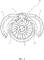
- FIG. 2 an aft view of nacelle 100 in a closed position is illustrated according to various embodiments.
- Left half 136 and right half 138 of thrust reverser 130 may be split along split line 232.
- Engine fan 210 is visible through the bypass air duct between IFS 132 and translating sleeve 134.
- Thrust reverser halves 136, 138 and core cowl halves 352, 354 are hinged open at hinges 170 in order to provide access to engine 310.
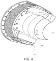
- FIG. 4 a perspective view of a thrust reverser having a pressure relief assembly 420 is illustrated according to various embodiments.
- the pressure relief assembly 420 is coupled to the IFS 132.
- the pressure relief assembly 420 may be located on the aft portion 414 of the IFS 132 to allow the pressurized fluid that builds up in a high pressure scenario, e.g., to prevent a burst duct scenario, to vent directly to ambient air.
- the thrust reverser may comprise a translating sleeve forming the outer wall of the fan duct.
- the annular surface between the trailing edge of the translating sleeve and the inner fixed structure is the fan exit plane.
- the pressure relief mechanism may be located aft of the fan exit plane.
- the thrust reverser may comprise an translating sleeve 134 forming the outer wall of the fan duct.
- the thrust reverser comprises an IFS 132, and a pressure relief assembly 420.
- the annular surface between the trailing edge of the translating sleeve and the inner fixed structure is the fan exit plane.
- the pressure relief assembly 420 may be located aft of the fan exit plane.
- the pressure relief assembly 420 may be located anywhere radially on a nacelle.
- the pressure relief assembly may be located on an engine bottom portion 516 of the IFS 132 to allow the pressure relief assembly to release a greater volume of fluid in a high pressure scenario, e.g., prior to a burst duct scenario.
- the engine bottom portion 516 is the bottom half of the thrust reverser 130. This will ensure that upon use, the pressure relief assembly 420 will open to ambient air. Additionally, when the pressure relief assembly is on the engine bottom portion 516 of the IFS 132, the pressure relief assembly 420 may open after an event, which would provide an indication that an event occurred based on visual inspection after an aircraft lands.
- the pressure relief assembly 420 comprises a pressure relief door 522 and a relief hinge 524, about which the pressure relief door 522 opens when the pressure relief assembly 420 is in use.
- the relief hinge 524 may be located at the forward edge of the pressure relief door 522 in order to ensure the pressure relief door 522 remains open after use.
- the relief hinge 524 may couple the pressure relief door 522 to the IFS 132 of the thrust reverser 130.
- the pressure relief assembly 420 comprises a latch mechanism 620 coupled to an IFS 132 of a thrust reverser, and a pressure relief door 522 comprising a bracket 632.
- the latch mechanism 620 comprises a pressure relief latch 622 and may comprise a latch housing 626 and a fulcrum 624 about which the pressure relief latch 622 pivots.
- the latch mechanism 620 is coupled to the pressure relief door 522 by engaging the pressure relief latch 622 to the bracket 632, fixing the pressure relief door 522 in place.
- the bracket 632 may comprise a keeper 634 designed to fix the pressure relief latch 622 in place during normal operation.
- the pressure relief door 522 is coupled to the IFS 132 at a hinge located opposite the bracket 632, as shown in FIG. 5 .
- the pressure relief door 522 and the IFS 132 may be separated by a gap 602, where the latch mechanism 620 couples the IFS 132 to the pressure relief door 522.
- the gap 602 may be sealed during normal operation. Since the latch mechanism comprises several components, whereas the bracket may simply comprise attachment features and a keeper, the latch mechanism may be significantly heavier compared to the bracket.
- the mass moment of inertia of the pressure relief door 522 may be significantly reduced. This configuration results in a pressure relief door 522 that is able to open more rapidly, relieving pressure faster, resulting in limited peak pressure during the burst duct event.
- a pressure relief assembly 420 is illustrated in an open position.
- An open position occurs when a pressure differential across the pressure relief door 522 reaches or exceeds a predetermined pressure threshold.
- the latch mechanism 620 may be configured to automatically release the pressure relief latch 622 once the pressure on the pressure relief door 522 reaches the predetermined pressure threshold (trigger pressure).
- the pressure relief latch 622 may pivot about the fulcrum 624 of the latch mechanism 620.
- the pressure relief latch 622 may release outward of the IFS 132 of the thrust reverser and into ambient air.
- the pressure relief door 522 may release automatically when the pressure reaches a defined pressure range.
- the defined pressure range may be 2-3.5 psid (13.79-24.13 kPa), depending on the design. In another example embodiment, the defined pressure range may be 2-5 psid (13.79-34.47 kPa).
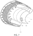
- the pressure relief arrangement 720 may be coupled to the IFS 712.
- the pressure relief arrangement 720 may be located on the aft portion 714 of the IFS 712 to allow the pressurized fluid that builds up in a high pressure scenario, e.g., a burst duct scenario, to vent directly to ambient air.
- the pressure relief arrangement 720 may comprise a frame 722 and a pressure relief door 724.
- the frame 722 may be coupled to the IFS 712 by welding, soldering or brazing the edges of the frame 722 to the IFS 712. Alternatively, the frame 722 may be coupled to the IFS 712 by standard fasteners, or any other mechanical fastening method known in the art.
- the thrust reverser may comprise an translating sleeve 802, an IFS 712, and a pressure relief arrangement 720.
- the pressure relief arrangement 720 may be located on an engine bottom portion 816 of the IFS 712 to allow the pressure relief arrangement to release a greater volume of fluid in a high pressure scenario, e.g., a burst duct scenario.
- the pressure relief arrangement 720 may be located aft of the translating sleeve 802. This will ensure that upon use, the pressure relief arrangement 720 will open to ambient air.
- the pressure relief mechanism may comprise a pressure relief door 724 and a relief hinge 824, about which the pressure relief door 724 opens when the pressure relief arrangement 720 is in use.
- the relief hinge 824 may be located at the forward edge of the pressure relief door 724 in order to ensure the pressure relief door 724 remains open after use.
- the relief hinge 824 may couple the pressure relief door 724 to the frame 722 of the pressure relief arrangement 720.
- the frame 722 may be coupled to the IFS 712 of the thrust reverser via mounting apertures 828.
- the frame 722 may be mounted to the IFS 712 by rivets, composite locks, screws, or any other fastening method known in the art.
- the frame 722 may be welded, soldered, or brazed to the IFS 712 without the use of mounting apertures.
- the pressure relief arrangement 720 may comprise a frame 722, a latch mechanism 920 coupled to the frame 722, and a pressure relief door 724 comprising a bracket 932.
- the latch mechanism 920 may comprise a latch housing 926, a pressure relief latch 922 and a fulcrum 924 about which the pressure relief latch 922 pivots.
- the latch mechanism 920 may be coupled to the pressure relief door 724 by engaging the pressure relief latch 922 to the bracket 932, fixing the pressure relief door 724 in place.
- the bracket 932 may comprise a keeper 934 designed to fix the pressure relief latch 922 in place during normal operation.
- the pressure relief door may be coupled to the frame 722 at a hinge located opposite the bracket 932, as shown in FIG. 8 .
- the pressure relief door 724 and the frame 722 may be separated by a gap 902, where the latch mechanism 920 couples the frame 722 to the pressure relief door 724.
- the gap 902 may be sealed during normal operation.
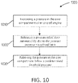
- the second step, block 1020 is to release a pressure relief door coupled to a thrust reverser via a fixed latch and a hinge. Both the pressure relief door and the fixed latch may release radially outward of the thrust reverser, as shown in FIG.
- the increased pressure is exerted on the latch that is fixed to the IFS as well as the pressure relief door.
- the fixed latch may release the bracket that is coupled to the pressure relief door that results in an opening for a pressurized fluid, such as air, to escape.
- a pressurized fluid such as air
- this method may result in the pressure relief door 522 pivoting away from the fixed latch.
- the third step, block 1030, of relieving pressure in a core compartment may comprise reducing the pressure in the core compartment below the predetermined threshold pressure.
- the pressure relief door may be coupled to the thrust reverser by a non-biased hinge, so that the pressure relief door may remain open after an event. This may permit the pressure in the core compartment to be reduced below the predetermined threshold pressure.
- the pressure in the core compartment will eventually reach a steady state pressure below the predetermined threshold pressure and alleviating any potential structural damage to the aircraft engine.
- the first step, block 1110 may comprise fastening a latch mechanism to a frame.
- the frame may comprise an aperture configured to receive a pressure relief door.
- the latch mechanism may be placed along one side of the perimeter and hang over the edge of the aperture after block 1110.
- the second step, block 1120 may comprise coupling a non-biased hinge to the frame at a side location along the perimeter of the aperture and opposite the latch.
- the non-biased hinge and the latch mechanism may be fastened to frame by rivets, bolts, screws, or similar fastening methods known in the art.
- the third step, block 1130 may comprise coupling a pressure relief door to the non-biased hinge.
- the pressure relief door may comprise a bracket opposite the hinge attachment location.
- the fourth step, block 1140 may comprise engaging the bracket coupled to the pressure relief door with the latch mechanism from block 1110. Once engaged, the latch mechanism may hold the pressure relief door in place. The latch mechanism and bracket may be configured to release once the pressure relief door exceeds a specific pressure.
- the result may be a pressure relief arrangement that may installable on various components.
- the fifth step, block 1150 may comprising installing the pressure relief arrangement on an inner fixed structure of a thrust reverser.
- the pressure relief arrangement may be installed by rivets, bolts, screws, or similar fastening methods.
- the pressure relief arrangement may be installed aft of the translating sleeve to ensure any escaping fluid releases to ambient air.
- the pressure relief assembly may be installed on engine bottom to provide maintenance with an indication if the pressure relief arrangement was used during a previous flight.
- references to "one embodiment”, “an embodiment”, “various embodiments”, etc. indicate that the embodiment described may include a particular feature, structure, or characteristic, but every embodiment may not necessarily include the particular feature, structure, or characteristic. Moreover, such phrases are not necessarily referring to the same embodiment. Further, when a particular feature, structure, or characteristic is described in connection with an embodiment, it is submitted that it is within the knowledge of one skilled in the art to affect such feature, structure, or characteristic in connection with other embodiments whether or not explicitly described. After reading the description, it will be apparent to one skilled in the relevant art(s) how to implement the disclosure in alternative embodiments.
Landscapes
- Engineering & Computer Science (AREA)
- Aviation & Aerospace Engineering (AREA)
- Chemical & Material Sciences (AREA)
- Combustion & Propulsion (AREA)
- Mechanical Engineering (AREA)
- General Engineering & Computer Science (AREA)
- Manufacturing & Machinery (AREA)
- Transportation (AREA)
- Structures Of Non-Positive Displacement Pumps (AREA)
- Connection Of Plates (AREA)
Description
- The disclosure generally relates to turbofan propulsion systems for an aircraft. More particularly, the disclosure relates to pressure relief for a nacelle for a turbofan propulsion system.
- Modern aircraft may utilize one or more turbofan propulsion systems powered by a gas turbine engine. The propulsion system may include a nacelle, which is a system of components that house the engine and its ancillary systems, and help form aerodynamic surfaces for flight, including a fan bypass air duct. Often, the nacelle includes a thrust reverser. The thrust reverser includes an inner fixed structure ("IFS") surrounding the engine which forms part of the interior surface of the bypass air duct through the thrust reverser.
- The volume between the IFS and the engine core defines the core compartment. In the core compartment, there are high pressure, high temperature pneumatic ducts that can fail, which would lead to catastrophic failure of the IFS structure. In order to relieve this rapid pressurization, pressure relief doors are provided that limit the pressure in the compartment to acceptable levels until the engine is shut down. Similar conditions can be found in other compartments where high pressure pneumatic ducts are present.
-
EP 3115562 A1 discloses a prior art nacelle according to the preamble of claim 1.US 4825644 A ,FR 2920135 A1 EP 2987985 A1 disclose other prior art systems. - According to the invention, the present disclosure provides a nacelle as defined in claim 1. Optional features of the invention are set out in the dependent claims.
- The subject matter of the present disclosure is particularly pointed out and distinctly claimed in the concluding portion of the specification. A more complete understanding of the present disclosure, however, may best be obtained by referring to the detailed description and claims when considered in connection with the drawing figures, wherein like numerals denote like elements.
-
FIG. 1 illustrates a perspective view of a nacelle in accordance with various embodiments of the disclosure; -
FIG. 2 illustrates an aft view of a nacelle in a closed position in accordance with various embodiments of the disclosure; -
FIG. 3 illustrates an aft view of a nacelle in an open position in accordance with various embodiments of the disclosure; -
FIG. 4 illustrates a perspective view of a thrust reverser having a pressure relief assembly in accordance with various embodiments of the disclosure; -
FIG. 5 illustrates a side view of a thrust reverser having a pressure relief assembly in accordance with various embodiments of the disclosure; -
FIG. 6A illustrates a pressure relief assembly in accordance with various embodiments; -
FIG. 6B illustrates a pressure relief assembly in accordance with various embodiments; and -
FIG. 7 illustrates a perspective view of a thrust reverser having a pressure relief arrangement in accordance with various embodiments of the disclosure; -
FIG. 8 illustrates a side view of a thrust reverser having a pressure relief arrangement in accordance with various embodiments of the disclosure; -
FIG. 9 illustrates a pressure relief arrangement in accordance with various embodiments; -
FIG. 10 illustrates a method of use of nacelle pressure relief in accordance with various embodiments. -
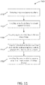
FIG. 11 illustrates a method of manufacture of a pressure relief arrangement installable on a thrust reverser in accordance with various embodiments. - The detailed description of various embodiments herein makes reference to the accompanying drawings, which show various embodiments by way of illustration. While these various embodiments are described in sufficient detail to enable those skilled in the art to practice the inventions, it should be understood that other embodiments may be realized and that logical, chemical and mechanical changes may be made without departing from the scope of the inventions. Thus, the detailed description herein is presented for purposes of illustration only and not of limitation.
- Systems for limiting deflections and stress in a nacelle with latches are disclosed below in accordance with various embodiments. During flight, an engine duct may burst causing an increase in pressure inside a core compartment surrounding the engine, or other conditions might exist which create a higher pressure inside of the core compartment than outside, resulting in a net force radially outward against the thrust reverser. Also, conditions might exist where a forward portion of the thrust reverser deflects outboard and begins to scoop the high velocity fan air stream in the bypass air duct, which can result in pressures and/or forces difficult to control that challenge the continued integrity of the thrust reverser structure. Pressure relief doors may be employed to prevent deflections of the thrust reverser structures. Proposed herein are pressure relief solutions which unlatch automatically to provide pressure relief when it is needed to tend to prevent deflections of the thrust reverser structure and may provide an indication to grounds crews that an issue occurred during flight.
- Referring to
FIG. 1 , anacelle 100 for a gas turbine engine is illustrated according to various embodiments.Nacelle 100 may comprise aninlet 110, afan cowl 120, and a thrust reverser 130. Nacelle 100 may be coupled to apylon 140, which may mount thenacelle 100 to an aircraft wing or aircraft body.Thrust reverser 130 comprises an inner fixed structure ("IFS") 132 and may comprise atranslating sleeve 134. Bypass air from an engine fan may flow in a generally annular bypass air duct defined between the IFS 132 and the translatingsleeve 134. The IFS 132 may be formed together with or be coupled to at its aft end acore cowl 150, which in turn is adjacent to anozzle 160 for core engine exhaust air. The thrust reverser 130 may further be split into aleft half 136 and aright half 138, such that there is, for example, a left half and a right half of IFS 132. Theleft half 136 and theright half 138 may be hinged to thepylon 140 athinges 170. Theleft half 136 and theright half 138 may hinge open athinges 170 in order to provide access to the engine for inspection or servicing. The left and right halves of the IFS 132 may together help form a core compartment around the engine when the left andright halves - Referring to
FIG. 2 , an aft view ofnacelle 100 in a closed position is illustrated according to various embodiments.Left half 136 andright half 138 ofthrust reverser 130 may be split alongsplit line 232.Engine fan 210 is visible through the bypass air duct between IFS 132 and translatingsleeve 134. - Referring to
FIG. 3 , an aft view ofnacelle 100 with thethrust reverser halves Thrust reverser halves core cowl halves hinges 170 in order to provide access toengine 310. - Referring to
FIG. 4 , a perspective view of a thrust reverser having apressure relief assembly 420 is illustrated according to various embodiments. For ease of reference, the translating sleeve of the thrust reverser is removed in the illustration. Thepressure relief assembly 420 is coupled to the IFS 132. Thepressure relief assembly 420 may be located on theaft portion 414 of the IFS 132 to allow the pressurized fluid that builds up in a high pressure scenario, e.g., to prevent a burst duct scenario, to vent directly to ambient air. The thrust reverser may comprise a translating sleeve forming the outer wall of the fan duct. The annular surface between the trailing edge of the translating sleeve and the inner fixed structure is the fan exit plane. The pressure relief mechanism may be located aft of the fan exit plane. - Referring to
FIG. 5 , a side view of athrust reverser 130 having apressure relief assembly 420 is illustrated according to various embodiments. The thrust reverser may comprise an translatingsleeve 134 forming the outer wall of the fan duct. The thrust reverser comprises anIFS 132, and apressure relief assembly 420. The annular surface between the trailing edge of the translating sleeve and the inner fixed structure is the fan exit plane. Thepressure relief assembly 420 may be located aft of the fan exit plane. Thepressure relief assembly 420 may be located anywhere radially on a nacelle. In an example embodiment, the pressure relief assembly may be located on anengine bottom portion 516 of theIFS 132 to allow the pressure relief assembly to release a greater volume of fluid in a high pressure scenario, e.g., prior to a burst duct scenario. Theengine bottom portion 516 is the bottom half of thethrust reverser 130. This will ensure that upon use, thepressure relief assembly 420 will open to ambient air. Additionally, when the pressure relief assembly is on theengine bottom portion 516 of theIFS 132, thepressure relief assembly 420 may open after an event, which would provide an indication that an event occurred based on visual inspection after an aircraft lands. Further, thepressure relief assembly 420 comprises apressure relief door 522 and arelief hinge 524, about which thepressure relief door 522 opens when thepressure relief assembly 420 is in use. Therelief hinge 524 may be located at the forward edge of thepressure relief door 522 in order to ensure thepressure relief door 522 remains open after use. Therelief hinge 524 may couple thepressure relief door 522 to theIFS 132 of thethrust reverser 130. - Referring to
FIG. 6A , apressure relief assembly 420 is illustrated according to various embodiments. Thepressure relief assembly 420 comprises alatch mechanism 620 coupled to anIFS 132 of a thrust reverser, and apressure relief door 522 comprising abracket 632. Thelatch mechanism 620 comprises apressure relief latch 622 and may comprise alatch housing 626 and afulcrum 624 about which thepressure relief latch 622 pivots. Thelatch mechanism 620 is coupled to thepressure relief door 522 by engaging thepressure relief latch 622 to thebracket 632, fixing thepressure relief door 522 in place. Thebracket 632 may comprise akeeper 634 designed to fix thepressure relief latch 622 in place during normal operation. Thepressure relief door 522 is coupled to theIFS 132 at a hinge located opposite thebracket 632, as shown inFIG. 5 . Thepressure relief door 522 and theIFS 132 may be separated by agap 602, where thelatch mechanism 620 couples theIFS 132 to thepressure relief door 522. In various embodiments, thegap 602 may be sealed during normal operation. Since the latch mechanism comprises several components, whereas the bracket may simply comprise attachment features and a keeper, the latch mechanism may be significantly heavier compared to the bracket. Thus, by placing thebracket 632 on thepressure relief door 522, as opposed to placing thelatch mechanism 620 on thepressure relief door 522, the mass moment of inertia of thepressure relief door 522 may be significantly reduced. This configuration results in apressure relief door 522 that is able to open more rapidly, relieving pressure faster, resulting in limited peak pressure during the burst duct event. - Referring to
FIG. 6B , apressure relief assembly 420 is illustrated in an open position. An open position occurs when a pressure differential across thepressure relief door 522 reaches or exceeds a predetermined pressure threshold. Thelatch mechanism 620 may be configured to automatically release thepressure relief latch 622 once the pressure on thepressure relief door 522 reaches the predetermined pressure threshold (trigger pressure). When in use, thepressure relief latch 622 may pivot about thefulcrum 624 of thelatch mechanism 620. Thepressure relief latch 622 may release outward of theIFS 132 of the thrust reverser and into ambient air. In an example embodiment, thepressure relief door 522 may release automatically when the pressure reaches a defined pressure range. In an example embodiment the defined pressure range may be 2-3.5 psid (13.79-24.13 kPa), depending on the design. In another example embodiment, the defined pressure range may be 2-5 psid (13.79-34.47 kPa). Once thepressure relief latch 622 releases thepressure relief door 522, it will swing outboard relieving the pressure buildup in the compartment. The compartment pressure may peak as the pressure relief door rotates outboard, but it may stabilize to a steady state pressure when the door reaches an equilibrium position. - Referring to
FIG. 7 , a perspective view of a thrust reverser having apressure relief arrangement 720 is illustrated according to various embodiments. For ease of reference, the translating sleeve of the thrust reverser is removed in the illustration. Thepressure relief arrangement 720 may be coupled to theIFS 712. Thepressure relief arrangement 720 may be located on theaft portion 714 of theIFS 712 to allow the pressurized fluid that builds up in a high pressure scenario, e.g., a burst duct scenario, to vent directly to ambient air. Thepressure relief arrangement 720 may comprise aframe 722 and apressure relief door 724. Theframe 722 may be coupled to theIFS 712 by welding, soldering or brazing the edges of theframe 722 to theIFS 712. Alternatively, theframe 722 may be coupled to theIFS 712 by standard fasteners, or any other mechanical fastening method known in the art. - Referring to
FIG. 8 , a side view of a thrust reverser having apressure relief arrangement 720 is illustrated according to various embodiments. The thrust reverser may comprise an translatingsleeve 802, anIFS 712, and apressure relief arrangement 720. Thepressure relief arrangement 720 may be located on anengine bottom portion 816 of theIFS 712 to allow the pressure relief arrangement to release a greater volume of fluid in a high pressure scenario, e.g., a burst duct scenario. Thepressure relief arrangement 720 may be located aft of the translatingsleeve 802. This will ensure that upon use, thepressure relief arrangement 720 will open to ambient air. Additionally, when thepressure relief arrangement 720 is on theengine bottom portion 816 of theIFS 712, thepressure relief arrangement 720 would remain open after an event, which would provide an indication that an event occurred based on visual inspection after an aircraft lands. Further, the pressure relief mechanism may comprise apressure relief door 724 and arelief hinge 824, about which thepressure relief door 724 opens when thepressure relief arrangement 720 is in use. Therelief hinge 824 may be located at the forward edge of thepressure relief door 724 in order to ensure thepressure relief door 724 remains open after use. Therelief hinge 824 may couple thepressure relief door 724 to theframe 722 of thepressure relief arrangement 720. Theframe 722 may be coupled to theIFS 712 of the thrust reverser via mountingapertures 828. Any mounting method known in the art may be utilized. For example, theframe 722 may be mounted to theIFS 712 by rivets, composite locks, screws, or any other fastening method known in the art. Alternatively, theframe 722 may be welded, soldered, or brazed to theIFS 712 without the use of mounting apertures. - Referring to
FIG. 9 , apressure relief arrangement 720 is illustrated according to various embodiments. Thepressure relief arrangement 720 may comprise aframe 722, alatch mechanism 920 coupled to theframe 722, and apressure relief door 724 comprising abracket 932. Thelatch mechanism 920 may comprise alatch housing 926, apressure relief latch 922 and afulcrum 924 about which thepressure relief latch 922 pivots. Thelatch mechanism 920 may be coupled to thepressure relief door 724 by engaging thepressure relief latch 922 to thebracket 932, fixing thepressure relief door 724 in place. Thebracket 932 may comprise akeeper 934 designed to fix thepressure relief latch 922 in place during normal operation. The pressure relief door may be coupled to theframe 722 at a hinge located opposite thebracket 932, as shown inFIG. 8 . Thepressure relief door 724 and theframe 722 may be separated by agap 902, where thelatch mechanism 920 couples theframe 722 to thepressure relief door 724. In various embodiments, thegap 902 may be sealed during normal operation. By placing thebracket 932 on thepressure relief door 724, as opposed to placing thelatch mechanism 920 on the pressure relief door, the mass moment of inertia of thepressure relief door 724 may be significantly reduced. This configuration results in apressure relief door 724 that is able to open more rapidly, relieving pressure faster, resulting in limited peak pressure during the burst duct event. - Referring to
FIG 10 , a method of use of relieving pressure in a core compartment of anaircraft engine 1000 is illustrated according to various embodiments. The first step,block 1010, of relieving pressure in a core compartment comprises increasing a pressure in the core compartment of an aircraft engine. This may occur during a high pressure engine scenario, and the intent is to prevent a duct in the engine from bursting due to the high pressure scenario. Without a pressure relief arrangement, the IFS of a thrust reverser would need to be significantly stiffer to handle the structural loads of the pressure increase. The second step,block 1020, is to release a pressure relief door coupled to a thrust reverser via a fixed latch and a hinge. Both the pressure relief door and the fixed latch may release radially outward of the thrust reverser, as shown inFIG. 6B . The increased pressure is exerted on the latch that is fixed to the IFS as well as the pressure relief door. The fixed latch may release the bracket that is coupled to the pressure relief door that results in an opening for a pressurized fluid, such as air, to escape. Referring back toFIG. 6B , this method may result in thepressure relief door 522 pivoting away from the fixed latch. The third step,block 1030, of relieving pressure in a core compartment may comprise reducing the pressure in the core compartment below the predetermined threshold pressure. The pressure relief door may be coupled to the thrust reverser by a non-biased hinge, so that the pressure relief door may remain open after an event. This may permit the pressure in the core compartment to be reduced below the predetermined threshold pressure. The pressure in the core compartment will eventually reach a steady state pressure below the predetermined threshold pressure and alleviating any potential structural damage to the aircraft engine. - Referring to
FIG 11 , a method of manufacturing a pressure relief arrangement installable on a thrust reverser of anacelle 1100 is illustrated according to various embodiments. The first step, block 1110 may comprise fastening a latch mechanism to a frame. The frame may comprise an aperture configured to receive a pressure relief door. The latch mechanism may be placed along one side of the perimeter and hang over the edge of the aperture afterblock 1110. The second step, block 1120 may comprise coupling a non-biased hinge to the frame at a side location along the perimeter of the aperture and opposite the latch. The non-biased hinge and the latch mechanism may be fastened to frame by rivets, bolts, screws, or similar fastening methods known in the art. - The third step,
block 1130, may comprise coupling a pressure relief door to the non-biased hinge. The pressure relief door may comprise a bracket opposite the hinge attachment location. The fourth step,block 1140, may comprise engaging the bracket coupled to the pressure relief door with the latch mechanism fromblock 1110. Once engaged, the latch mechanism may hold the pressure relief door in place. The latch mechanism and bracket may be configured to release once the pressure relief door exceeds a specific pressure. Afterblock 1140, the result may be a pressure relief arrangement that may installable on various components. The fifth step,block 1150, may comprising installing the pressure relief arrangement on an inner fixed structure of a thrust reverser. The pressure relief arrangement may be installed by rivets, bolts, screws, or similar fastening methods. The pressure relief arrangement may be installed aft of the translating sleeve to ensure any escaping fluid releases to ambient air. The pressure relief assembly may be installed on engine bottom to provide maintenance with an indication if the pressure relief arrangement was used during a previous flight. - In the detailed description herein, references to "one embodiment", "an embodiment", "various embodiments", etc., indicate that the embodiment described may include a particular feature, structure, or characteristic, but every embodiment may not necessarily include the particular feature, structure, or characteristic. Moreover, such phrases are not necessarily referring to the same embodiment. Further, when a particular feature, structure, or characteristic is described in connection with an embodiment, it is submitted that it is within the knowledge of one skilled in the art to affect such feature, structure, or characteristic in connection with other embodiments whether or not explicitly described. After reading the description, it will be apparent to one skilled in the relevant art(s) how to implement the disclosure in alternative embodiments.
- Benefits, other advantages, and solutions to problems have been described herein with regard to specific embodiments. Furthermore, the connecting lines shown in the various figures contained herein are intended to represent various functional relationships and/or physical couplings between the various elements. It should be noted that many alternative or additional functional relationships or physical connections may be present in a practical system. However, the benefits, advantages, solutions to problems, and any elements that may cause any benefit, advantage, or solution to occur or become more pronounced are not to be construed as critical, required, or essential features or elements of the inventions. The scope of the inventions is accordingly to be limited by nothing other than the appended claims.
Claims (4)
- A nacelle (100) for a turbofan propulsion system for an aircraft, the nacelle (100) comprising:an inner fixed structure (132);a pressure relief assembly (420) comprising:a latch mechanism (620) comprising a pressure relief latch (622) coupled to the inner fixed structure (132);a pressure relief door (522) comprising a bracket (632), the pressure relief latch (622) configured to hold the pressure relief door (522) in a closed position;wherein:the pressure relief door (522) comprises a hinge (524) about which the pressure relief door (522) opens when the pressure relief assembly (420) is in use, the hinge (524) is coupled to the inner fixed structure (132) opposite the bracket (632), the bracket (632) is placed on the pressure relief door (522), characterised in that,the latch mechanism (620) is coupled to the pressure relief door (522) by engaging the pressure relief latch (622) to the bracket (632), fixing the pressure relief door (522) in place, and the pressure relief latch (622) is configured to automatically release radially outward in response to an increase in pressure on the pressure relief door (522).
- The nacelle (100) of claim 1, wherein the pressure relief assembly (420) is located on a bottom portion (516) of the inner fixed structure (132).
- The nacelle (100) of any preceding claim, further comprising a translating sleeve (134), wherein the pressure relief assembly (420) is located aft of the translating sleeve (134).
- The nacelle (100) of any preceding claim, wherein the inner fixed structure (132) is configured to be mounted to a thrust reverser (130) of the nacelle (100).
Applications Claiming Priority (2)
| Application Number | Priority Date | Filing Date | Title |
|---|---|---|---|
| US201862757024P | 2018-11-07 | 2018-11-07 | |
| US16/255,189 US11077956B2 (en) | 2018-11-07 | 2019-01-23 | Pressure relief assembly |
Publications (2)
| Publication Number | Publication Date |
|---|---|
| EP3650334A1 EP3650334A1 (en) | 2020-05-13 |
| EP3650334B1 true EP3650334B1 (en) | 2022-08-03 |
Family
ID=68502968
Family Applications (1)
| Application Number | Title | Priority Date | Filing Date |
|---|---|---|---|
| EP19207801.2A Active EP3650334B1 (en) | 2018-11-07 | 2019-11-07 | Pressure relief assembly |
Country Status (2)
| Country | Link |
|---|---|
| US (2) | US11077956B2 (en) |
| EP (1) | EP3650334B1 (en) |
Families Citing this family (3)
| Publication number | Priority date | Publication date | Assignee | Title |
|---|---|---|---|---|
| US12187445B2 (en) | 2021-03-31 | 2025-01-07 | The Boeing Company | Guide systems for installing aircraft structures |
| EP4067239B1 (en) * | 2021-03-31 | 2024-07-24 | The Boeing Company | Guide systems for installing aircraft structures such as thrust reversers |
| FR3126001A1 (en) * | 2021-08-03 | 2023-02-10 | Airbus Operations | ASSEMBLY FOR A NACELLE OF AN AIRCRAFT ENGINE, THE SUCH ASSEMBLY COMPRISING A FIXED HOOD AND A HOOD MOBILE MOUNTED ON THE FIXED HOOD |
Family Cites Families (11)
| Publication number | Priority date | Publication date | Assignee | Title |
|---|---|---|---|---|
| US4825644A (en) * | 1987-11-12 | 1989-05-02 | United Technologies Corporation | Ventilation system for a nacelle |
| US5623820A (en) * | 1995-02-03 | 1997-04-29 | The Boeing Company | Flow control apparatus for gas turbine engine installation pressure relief doors |
| US5765883A (en) | 1995-07-14 | 1998-06-16 | Hartwell Corporation | Adjustable pressure relief latch |
| WO2003104080A1 (en) * | 2002-06-06 | 2003-12-18 | Remmele Engineering, Inc. | Aircraft door system and method of making and installing the same |
| FR2920135B1 (en) | 2008-07-21 | 2009-11-20 | Aircelle Sa | NACELLE EQUIPPED WITH AT LEAST ONE OVERPRESSURE TRAPPER |
| FR2939768B1 (en) | 2008-12-12 | 2011-09-09 | Aircelle Sa | PRESSURE TRAPPER TO BE MOUNTED ON A WALL OF A TURBOREACTOR NACELLE |
| FR2960854B1 (en) * | 2010-06-04 | 2012-07-20 | Airbus Operations Sas | DOUBLE FUNCTION DOOR FOR AIRCRAFT ENGINE NACELLE |
| FR2978424B1 (en) | 2011-07-26 | 2014-05-16 | Lisi Aerospace | OVERPRESSURE LATCH |
| US10487690B2 (en) | 2014-08-18 | 2019-11-26 | Rohr, Inc. | Actively controlled cooling air exhaust door on an aircraft engine nacelle |
| US10060287B2 (en) | 2015-07-09 | 2018-08-28 | Rohr, Inc | Pressure relief door assembly |
| US10240389B2 (en) | 2015-09-30 | 2019-03-26 | Arconic Inc. | Pressure relief door |
-
2019
- 2019-01-23 US US16/255,189 patent/US11077956B2/en active Active
- 2019-11-07 EP EP19207801.2A patent/EP3650334B1/en active Active
-
2021
- 2021-06-03 US US17/337,692 patent/US11542027B2/en active Active
Also Published As
| Publication number | Publication date |
|---|---|
| US20200140105A1 (en) | 2020-05-07 |
| US20210291997A1 (en) | 2021-09-23 |
| EP3650334A1 (en) | 2020-05-13 |
| US11542027B2 (en) | 2023-01-03 |
| US11077956B2 (en) | 2021-08-03 |
Similar Documents
| Publication | Publication Date | Title |
|---|---|---|
| US11542027B2 (en) | Pressure relief assembly | |
| US11125112B2 (en) | Inner fixed structure leading edge latch | |
| EP2455281B1 (en) | Spring loaded pressure relief door for a nacelle cowl | |
| US10507932B2 (en) | Automatic deflection limiting latches for a thrust reverser | |
| US9366202B2 (en) | System and method for captured inner fixed structure | |
| US20100059634A1 (en) | Locking system for a movable nacelle cowl | |
| CA2470926A1 (en) | Aircraft engine in which there is a small clearance separating the fan cowls and the thrust inverter cowls | |
| EP3115562B1 (en) | Pressure relief door assembly | |
| US9714612B2 (en) | Drag link fitting and vent combination | |
| US10618664B2 (en) | Self-latching nacelle | |
| US20210310440A1 (en) | Nacelle with independent opening thrust reverser section | |
| US20160280384A1 (en) | High visibility latch handle | |
| EP3326916B1 (en) | Nacelle latch alignment | |
| EP3845461B1 (en) | Dual axis hinge radial displacement limiter | |
| US20230287802A1 (en) | Leak detection system for anti-ice ducts | |
| US11525372B2 (en) | Diaphragm latch | |
| EP3748174B1 (en) | Fastener assembly for nacelle pressure-relief doors | |
| EP3647203B1 (en) | Nacelle cowl hinge | |
| EP3708484B1 (en) | Pressure relief door rotating exhaust deflector | |
| EP4019407B1 (en) | Fan cowl failsafe gooseneck assembly |
Legal Events
| Date | Code | Title | Description |
|---|---|---|---|
| PUAI | Public reference made under article 153(3) epc to a published international application that has entered the european phase |
Free format text: ORIGINAL CODE: 0009012 |
|
| STAA | Information on the status of an ep patent application or granted ep patent |
Free format text: STATUS: THE APPLICATION HAS BEEN PUBLISHED |
|
| AK | Designated contracting states |
Kind code of ref document: A1 Designated state(s): AL AT BE BG CH CY CZ DE DK EE ES FI FR GB GR HR HU IE IS IT LI LT LU LV MC MK MT NL NO PL PT RO RS SE SI SK SM TR |
|
| AX | Request for extension of the european patent |
Extension state: BA ME |
|
| STAA | Information on the status of an ep patent application or granted ep patent |
Free format text: STATUS: REQUEST FOR EXAMINATION WAS MADE |
|
| 17P | Request for examination filed |
Effective date: 20201113 |
|
| RBV | Designated contracting states (corrected) |
Designated state(s): AL AT BE BG CH CY CZ DE DK EE ES FI FR GB GR HR HU IE IS IT LI LT LU LV MC MK MT NL NO PL PT RO RS SE SI SK SM TR |
|
| STAA | Information on the status of an ep patent application or granted ep patent |
Free format text: STATUS: EXAMINATION IS IN PROGRESS |
|
| 17Q | First examination report despatched |
Effective date: 20210325 |
|
| GRAP | Despatch of communication of intention to grant a patent |
Free format text: ORIGINAL CODE: EPIDOSNIGR1 |
|
| STAA | Information on the status of an ep patent application or granted ep patent |
Free format text: STATUS: GRANT OF PATENT IS INTENDED |
|
| INTG | Intention to grant announced |
Effective date: 20220224 |
|
| GRAS | Grant fee paid |
Free format text: ORIGINAL CODE: EPIDOSNIGR3 |
|
| GRAA | (expected) grant |
Free format text: ORIGINAL CODE: 0009210 |
|
| STAA | Information on the status of an ep patent application or granted ep patent |
Free format text: STATUS: THE PATENT HAS BEEN GRANTED |
|
| AK | Designated contracting states |
Kind code of ref document: B1 Designated state(s): AL AT BE BG CH CY CZ DE DK EE ES FI FR GB GR HR HU IE IS IT LI LT LU LV MC MK MT NL NO PL PT RO RS SE SI SK SM TR |
|
| REG | Reference to a national code |
Ref country code: AT Ref legal event code: REF Ref document number: 1508546 Country of ref document: AT Kind code of ref document: T Effective date: 20220815 Ref country code: CH Ref legal event code: EP |
|
| REG | Reference to a national code |
Ref country code: DE Ref legal event code: R096 Ref document number: 602019017717 Country of ref document: DE |
|
| REG | Reference to a national code |
Ref country code: IE Ref legal event code: FG4D |
|
| REG | Reference to a national code |
Ref country code: LT Ref legal event code: MG9D |
|
| REG | Reference to a national code |
Ref country code: NL Ref legal event code: MP Effective date: 20220803 |
|
| PG25 | Lapsed in a contracting state [announced via postgrant information from national office to epo] |
Ref country code: SE Free format text: LAPSE BECAUSE OF FAILURE TO SUBMIT A TRANSLATION OF THE DESCRIPTION OR TO PAY THE FEE WITHIN THE PRESCRIBED TIME-LIMIT Effective date: 20220803 Ref country code: RS Free format text: LAPSE BECAUSE OF FAILURE TO SUBMIT A TRANSLATION OF THE DESCRIPTION OR TO PAY THE FEE WITHIN THE PRESCRIBED TIME-LIMIT Effective date: 20220803 Ref country code: PT Free format text: LAPSE BECAUSE OF FAILURE TO SUBMIT A TRANSLATION OF THE DESCRIPTION OR TO PAY THE FEE WITHIN THE PRESCRIBED TIME-LIMIT Effective date: 20221205 Ref country code: NO Free format text: LAPSE BECAUSE OF FAILURE TO SUBMIT A TRANSLATION OF THE DESCRIPTION OR TO PAY THE FEE WITHIN THE PRESCRIBED TIME-LIMIT Effective date: 20221103 Ref country code: NL Free format text: LAPSE BECAUSE OF FAILURE TO SUBMIT A TRANSLATION OF THE DESCRIPTION OR TO PAY THE FEE WITHIN THE PRESCRIBED TIME-LIMIT Effective date: 20220803 Ref country code: LV Free format text: LAPSE BECAUSE OF FAILURE TO SUBMIT A TRANSLATION OF THE DESCRIPTION OR TO PAY THE FEE WITHIN THE PRESCRIBED TIME-LIMIT Effective date: 20220803 Ref country code: LT Free format text: LAPSE BECAUSE OF FAILURE TO SUBMIT A TRANSLATION OF THE DESCRIPTION OR TO PAY THE FEE WITHIN THE PRESCRIBED TIME-LIMIT Effective date: 20220803 Ref country code: FI Free format text: LAPSE BECAUSE OF FAILURE TO SUBMIT A TRANSLATION OF THE DESCRIPTION OR TO PAY THE FEE WITHIN THE PRESCRIBED TIME-LIMIT Effective date: 20220803 Ref country code: ES Free format text: LAPSE BECAUSE OF FAILURE TO SUBMIT A TRANSLATION OF THE DESCRIPTION OR TO PAY THE FEE WITHIN THE PRESCRIBED TIME-LIMIT Effective date: 20220803 |
|
| REG | Reference to a national code |
Ref country code: AT Ref legal event code: MK05 Ref document number: 1508546 Country of ref document: AT Kind code of ref document: T Effective date: 20220803 |
|
| PG25 | Lapsed in a contracting state [announced via postgrant information from national office to epo] |
Ref country code: PL Free format text: LAPSE BECAUSE OF FAILURE TO SUBMIT A TRANSLATION OF THE DESCRIPTION OR TO PAY THE FEE WITHIN THE PRESCRIBED TIME-LIMIT Effective date: 20220803 Ref country code: IS Free format text: LAPSE BECAUSE OF FAILURE TO SUBMIT A TRANSLATION OF THE DESCRIPTION OR TO PAY THE FEE WITHIN THE PRESCRIBED TIME-LIMIT Effective date: 20221203 Ref country code: HR Free format text: LAPSE BECAUSE OF FAILURE TO SUBMIT A TRANSLATION OF THE DESCRIPTION OR TO PAY THE FEE WITHIN THE PRESCRIBED TIME-LIMIT Effective date: 20220803 Ref country code: GR Free format text: LAPSE BECAUSE OF FAILURE TO SUBMIT A TRANSLATION OF THE DESCRIPTION OR TO PAY THE FEE WITHIN THE PRESCRIBED TIME-LIMIT Effective date: 20221104 |
|
| PG25 | Lapsed in a contracting state [announced via postgrant information from national office to epo] |
Ref country code: SM Free format text: LAPSE BECAUSE OF FAILURE TO SUBMIT A TRANSLATION OF THE DESCRIPTION OR TO PAY THE FEE WITHIN THE PRESCRIBED TIME-LIMIT Effective date: 20220803 Ref country code: RO Free format text: LAPSE BECAUSE OF FAILURE TO SUBMIT A TRANSLATION OF THE DESCRIPTION OR TO PAY THE FEE WITHIN THE PRESCRIBED TIME-LIMIT Effective date: 20220803 Ref country code: DK Free format text: LAPSE BECAUSE OF FAILURE TO SUBMIT A TRANSLATION OF THE DESCRIPTION OR TO PAY THE FEE WITHIN THE PRESCRIBED TIME-LIMIT Effective date: 20220803 Ref country code: CZ Free format text: LAPSE BECAUSE OF FAILURE TO SUBMIT A TRANSLATION OF THE DESCRIPTION OR TO PAY THE FEE WITHIN THE PRESCRIBED TIME-LIMIT Effective date: 20220803 Ref country code: AT Free format text: LAPSE BECAUSE OF FAILURE TO SUBMIT A TRANSLATION OF THE DESCRIPTION OR TO PAY THE FEE WITHIN THE PRESCRIBED TIME-LIMIT Effective date: 20220803 |
|
| REG | Reference to a national code |
Ref country code: DE Ref legal event code: R097 Ref document number: 602019017717 Country of ref document: DE |
|
| PG25 | Lapsed in a contracting state [announced via postgrant information from national office to epo] |
Ref country code: SK Free format text: LAPSE BECAUSE OF FAILURE TO SUBMIT A TRANSLATION OF THE DESCRIPTION OR TO PAY THE FEE WITHIN THE PRESCRIBED TIME-LIMIT Effective date: 20220803 Ref country code: EE Free format text: LAPSE BECAUSE OF FAILURE TO SUBMIT A TRANSLATION OF THE DESCRIPTION OR TO PAY THE FEE WITHIN THE PRESCRIBED TIME-LIMIT Effective date: 20220803 |
|
| PLBE | No opposition filed within time limit |
Free format text: ORIGINAL CODE: 0009261 |
|
| STAA | Information on the status of an ep patent application or granted ep patent |
Free format text: STATUS: NO OPPOSITION FILED WITHIN TIME LIMIT |
|
| PG25 | Lapsed in a contracting state [announced via postgrant information from national office to epo] |
Ref country code: MC Free format text: LAPSE BECAUSE OF FAILURE TO SUBMIT A TRANSLATION OF THE DESCRIPTION OR TO PAY THE FEE WITHIN THE PRESCRIBED TIME-LIMIT Effective date: 20220803 Ref country code: AL Free format text: LAPSE BECAUSE OF FAILURE TO SUBMIT A TRANSLATION OF THE DESCRIPTION OR TO PAY THE FEE WITHIN THE PRESCRIBED TIME-LIMIT Effective date: 20220803 |
|
| REG | Reference to a national code |
Ref country code: CH Ref legal event code: PL |
|
| 26N | No opposition filed |
Effective date: 20230504 |
|
| REG | Reference to a national code |
Ref country code: BE Ref legal event code: MM Effective date: 20221130 |
|
| PG25 | Lapsed in a contracting state [announced via postgrant information from national office to epo] |
Ref country code: LI Free format text: LAPSE BECAUSE OF NON-PAYMENT OF DUE FEES Effective date: 20221130 Ref country code: CH Free format text: LAPSE BECAUSE OF NON-PAYMENT OF DUE FEES Effective date: 20221130 |
|
| PG25 | Lapsed in a contracting state [announced via postgrant information from national office to epo] |
Ref country code: SI Free format text: LAPSE BECAUSE OF FAILURE TO SUBMIT A TRANSLATION OF THE DESCRIPTION OR TO PAY THE FEE WITHIN THE PRESCRIBED TIME-LIMIT Effective date: 20220803 Ref country code: LU Free format text: LAPSE BECAUSE OF NON-PAYMENT OF DUE FEES Effective date: 20221107 |
|
| PG25 | Lapsed in a contracting state [announced via postgrant information from national office to epo] |
Ref country code: IE Free format text: LAPSE BECAUSE OF NON-PAYMENT OF DUE FEES Effective date: 20221107 |
|
| PG25 | Lapsed in a contracting state [announced via postgrant information from national office to epo] |
Ref country code: BE Free format text: LAPSE BECAUSE OF NON-PAYMENT OF DUE FEES Effective date: 20221130 |
|
| PG25 | Lapsed in a contracting state [announced via postgrant information from national office to epo] |
Ref country code: HU Free format text: LAPSE BECAUSE OF FAILURE TO SUBMIT A TRANSLATION OF THE DESCRIPTION OR TO PAY THE FEE WITHIN THE PRESCRIBED TIME-LIMIT; INVALID AB INITIO Effective date: 20191107 |
|
| PG25 | Lapsed in a contracting state [announced via postgrant information from national office to epo] |
Ref country code: CY Free format text: LAPSE BECAUSE OF FAILURE TO SUBMIT A TRANSLATION OF THE DESCRIPTION OR TO PAY THE FEE WITHIN THE PRESCRIBED TIME-LIMIT Effective date: 20220803 |
|
| PG25 | Lapsed in a contracting state [announced via postgrant information from national office to epo] |
Ref country code: MK Free format text: LAPSE BECAUSE OF FAILURE TO SUBMIT A TRANSLATION OF THE DESCRIPTION OR TO PAY THE FEE WITHIN THE PRESCRIBED TIME-LIMIT Effective date: 20220803 Ref country code: IT Free format text: LAPSE BECAUSE OF FAILURE TO SUBMIT A TRANSLATION OF THE DESCRIPTION OR TO PAY THE FEE WITHIN THE PRESCRIBED TIME-LIMIT Effective date: 20220803 |
|
| PG25 | Lapsed in a contracting state [announced via postgrant information from national office to epo] |
Ref country code: BG Free format text: LAPSE BECAUSE OF FAILURE TO SUBMIT A TRANSLATION OF THE DESCRIPTION OR TO PAY THE FEE WITHIN THE PRESCRIBED TIME-LIMIT Effective date: 20220803 |
|
| PG25 | Lapsed in a contracting state [announced via postgrant information from national office to epo] |
Ref country code: MT Free format text: LAPSE BECAUSE OF FAILURE TO SUBMIT A TRANSLATION OF THE DESCRIPTION OR TO PAY THE FEE WITHIN THE PRESCRIBED TIME-LIMIT Effective date: 20220803 |
|
| PG25 | Lapsed in a contracting state [announced via postgrant information from national office to epo] |
Ref country code: TR Free format text: LAPSE BECAUSE OF FAILURE TO SUBMIT A TRANSLATION OF THE DESCRIPTION OR TO PAY THE FEE WITHIN THE PRESCRIBED TIME-LIMIT Effective date: 20220803 |
|
| PGFP | Annual fee paid to national office [announced via postgrant information from national office to epo] |
Ref country code: DE Payment date: 20251022 Year of fee payment: 7 |
|
| PGFP | Annual fee paid to national office [announced via postgrant information from national office to epo] |
Ref country code: GB Payment date: 20251023 Year of fee payment: 7 |
|
| PGFP | Annual fee paid to national office [announced via postgrant information from national office to epo] |
Ref country code: FR Payment date: 20251023 Year of fee payment: 7 |
|
| P01 | Opt-out of the competence of the unified patent court (upc) registered |
Free format text: CASE NUMBER: UPC_APP_0018940_3650334/2025 Effective date: 20251222 |