EP3650332A1 - Assemblage constituant un isolant acoustique - Google Patents
Assemblage constituant un isolant acoustique Download PDFInfo
- Publication number
- EP3650332A1 EP3650332A1 EP19203729.9A EP19203729A EP3650332A1 EP 3650332 A1 EP3650332 A1 EP 3650332A1 EP 19203729 A EP19203729 A EP 19203729A EP 3650332 A1 EP3650332 A1 EP 3650332A1
- Authority
- EP
- European Patent Office
- Prior art keywords
- strip
- wall
- cone
- plate
- assembly
- Prior art date
- Legal status (The legal status is an assumption and is not a legal conclusion. Google has not performed a legal analysis and makes no representation as to the accuracy of the status listed.)
- Granted
Links
Images


Classifications
-
- B—PERFORMING OPERATIONS; TRANSPORTING
- B64—AIRCRAFT; AVIATION; COSMONAUTICS
- B64C—AEROPLANES; HELICOPTERS
- B64C1/00—Fuselages; Constructional features common to fuselages, wings, stabilising surfaces or the like
- B64C1/40—Sound or heat insulation, e.g. using insulation blankets
-
- F—MECHANICAL ENGINEERING; LIGHTING; HEATING; WEAPONS; BLASTING
- F02—COMBUSTION ENGINES; HOT-GAS OR COMBUSTION-PRODUCT ENGINE PLANTS
- F02C—GAS-TURBINE PLANTS; AIR INTAKES FOR JET-PROPULSION PLANTS; CONTROLLING FUEL SUPPLY IN AIR-BREATHING JET-PROPULSION PLANTS
- F02C7/00—Features, components parts, details or accessories, not provided for in, or of interest apart form groups F02C1/00 - F02C6/00; Air intakes for jet-propulsion plants
- F02C7/24—Heat or noise insulation
-
- E—FIXED CONSTRUCTIONS
- E04—BUILDING
- E04B—GENERAL BUILDING CONSTRUCTIONS; WALLS, e.g. PARTITIONS; ROOFS; FLOORS; CEILINGS; INSULATION OR OTHER PROTECTION OF BUILDINGS
- E04B1/00—Constructions in general; Structures which are not restricted either to walls, e.g. partitions, or floors or ceilings or roofs
- E04B1/62—Insulation or other protection; Elements or use of specified material therefor
- E04B1/74—Heat, sound or noise insulation, absorption, or reflection; Other building methods affording favourable thermal or acoustical conditions, e.g. accumulating of heat within walls
- E04B1/82—Heat, sound or noise insulation, absorption, or reflection; Other building methods affording favourable thermal or acoustical conditions, e.g. accumulating of heat within walls specifically with respect to sound only
- E04B1/84—Sound-absorbing elements
- E04B1/86—Sound-absorbing elements slab-shaped
-
- F—MECHANICAL ENGINEERING; LIGHTING; HEATING; WEAPONS; BLASTING
- F02—COMBUSTION ENGINES; HOT-GAS OR COMBUSTION-PRODUCT ENGINE PLANTS
- F02C—GAS-TURBINE PLANTS; AIR INTAKES FOR JET-PROPULSION PLANTS; CONTROLLING FUEL SUPPLY IN AIR-BREATHING JET-PROPULSION PLANTS
- F02C7/00—Features, components parts, details or accessories, not provided for in, or of interest apart form groups F02C1/00 - F02C6/00; Air intakes for jet-propulsion plants
- F02C7/04—Air intakes for gas-turbine plants or jet-propulsion plants
- F02C7/045—Air intakes for gas-turbine plants or jet-propulsion plants having provisions for noise suppression
-
- F—MECHANICAL ENGINEERING; LIGHTING; HEATING; WEAPONS; BLASTING
- F02—COMBUSTION ENGINES; HOT-GAS OR COMBUSTION-PRODUCT ENGINE PLANTS
- F02K—JET-PROPULSION PLANTS
- F02K1/00—Plants characterised by the form or arrangement of the jet pipe or nozzle; Jet pipes or nozzles peculiar thereto
- F02K1/78—Other construction of jet pipes
- F02K1/82—Jet pipe walls, e.g. liners
- F02K1/827—Sound absorbing structures or liners
-
- G—PHYSICS
- G10—MUSICAL INSTRUMENTS; ACOUSTICS
- G10K—SOUND-PRODUCING DEVICES; METHODS OR DEVICES FOR PROTECTING AGAINST, OR FOR DAMPING, NOISE OR OTHER ACOUSTIC WAVES IN GENERAL; ACOUSTICS NOT OTHERWISE PROVIDED FOR
- G10K11/00—Methods or devices for transmitting, conducting or directing sound in general; Methods or devices for protecting against, or for damping, noise or other acoustic waves in general
- G10K11/16—Methods or devices for protecting against, or for damping, noise or other acoustic waves in general
- G10K11/162—Selection of materials
- G10K11/168—Plural layers of different materials, e.g. sandwiches
-
- G—PHYSICS
- G10—MUSICAL INSTRUMENTS; ACOUSTICS
- G10K—SOUND-PRODUCING DEVICES; METHODS OR DEVICES FOR PROTECTING AGAINST, OR FOR DAMPING, NOISE OR OTHER ACOUSTIC WAVES IN GENERAL; ACOUSTICS NOT OTHERWISE PROVIDED FOR
- G10K11/00—Methods or devices for transmitting, conducting or directing sound in general; Methods or devices for protecting against, or for damping, noise or other acoustic waves in general
- G10K11/16—Methods or devices for protecting against, or for damping, noise or other acoustic waves in general
- G10K11/172—Methods or devices for protecting against, or for damping, noise or other acoustic waves in general using resonance effects
-
- B—PERFORMING OPERATIONS; TRANSPORTING
- B32—LAYERED PRODUCTS
- B32B—LAYERED PRODUCTS, i.e. PRODUCTS BUILT-UP OF STRATA OF FLAT OR NON-FLAT, e.g. CELLULAR OR HONEYCOMB, FORM
- B32B2307/00—Properties of the layers or laminate
- B32B2307/10—Properties of the layers or laminate having particular acoustical properties
- B32B2307/102—Insulating
-
- B—PERFORMING OPERATIONS; TRANSPORTING
- B32—LAYERED PRODUCTS
- B32B—LAYERED PRODUCTS, i.e. PRODUCTS BUILT-UP OF STRATA OF FLAT OR NON-FLAT, e.g. CELLULAR OR HONEYCOMB, FORM
- B32B2605/00—Vehicles
- B32B2605/18—Aircraft
-
- B—PERFORMING OPERATIONS; TRANSPORTING
- B32—LAYERED PRODUCTS
- B32B—LAYERED PRODUCTS, i.e. PRODUCTS BUILT-UP OF STRATA OF FLAT OR NON-FLAT, e.g. CELLULAR OR HONEYCOMB, FORM
- B32B3/00—Layered products comprising a layer with external or internal discontinuities or unevennesses, or a layer of non-planar shape; Layered products comprising a layer having particular features of form
- B32B3/10—Layered products comprising a layer with external or internal discontinuities or unevennesses, or a layer of non-planar shape; Layered products comprising a layer having particular features of form characterised by a discontinuous layer, i.e. formed of separate pieces of material
- B32B3/12—Layered products comprising a layer with external or internal discontinuities or unevennesses, or a layer of non-planar shape; Layered products comprising a layer having particular features of form characterised by a discontinuous layer, i.e. formed of separate pieces of material characterised by a layer of regularly- arranged cells, e.g. a honeycomb structure
-
- B—PERFORMING OPERATIONS; TRANSPORTING
- B32—LAYERED PRODUCTS
- B32B—LAYERED PRODUCTS, i.e. PRODUCTS BUILT-UP OF STRATA OF FLAT OR NON-FLAT, e.g. CELLULAR OR HONEYCOMB, FORM
- B32B3/00—Layered products comprising a layer with external or internal discontinuities or unevennesses, or a layer of non-planar shape; Layered products comprising a layer having particular features of form
- B32B3/26—Layered products comprising a layer with external or internal discontinuities or unevennesses, or a layer of non-planar shape; Layered products comprising a layer having particular features of form characterised by a particular shape of the outline of the cross-section of a continuous layer; characterised by a layer with cavities or internal voids ; characterised by an apertured layer
- B32B3/266—Layered products comprising a layer with external or internal discontinuities or unevennesses, or a layer of non-planar shape; Layered products comprising a layer having particular features of form characterised by a particular shape of the outline of the cross-section of a continuous layer; characterised by a layer with cavities or internal voids ; characterised by an apertured layer characterised by an apertured layer, the apertures going through the whole thickness of the layer, e.g. expanded metal, perforated layer, slit layer regular cells B32B3/12
-
- B—PERFORMING OPERATIONS; TRANSPORTING
- B64—AIRCRAFT; AVIATION; COSMONAUTICS
- B64D—EQUIPMENT FOR FITTING IN OR TO AIRCRAFT; FLIGHT SUITS; PARACHUTES; ARRANGEMENT OR MOUNTING OF POWER PLANTS OR PROPULSION TRANSMISSIONS IN AIRCRAFT
- B64D33/00—Arrangement in aircraft of power plant parts or auxiliaries not otherwise provided for
- B64D33/02—Arrangement in aircraft of power plant parts or auxiliaries not otherwise provided for of combustion air intakes
- B64D2033/0206—Arrangement in aircraft of power plant parts or auxiliaries not otherwise provided for of combustion air intakes comprising noise reduction means, e.g. acoustic liners
-
- E—FIXED CONSTRUCTIONS
- E04—BUILDING
- E04B—GENERAL BUILDING CONSTRUCTIONS; WALLS, e.g. PARTITIONS; ROOFS; FLOORS; CEILINGS; INSULATION OR OTHER PROTECTION OF BUILDINGS
- E04B1/00—Constructions in general; Structures which are not restricted either to walls, e.g. partitions, or floors or ceilings or roofs
- E04B1/62—Insulation or other protection; Elements or use of specified material therefor
- E04B1/74—Heat, sound or noise insulation, absorption, or reflection; Other building methods affording favourable thermal or acoustical conditions, e.g. accumulating of heat within walls
- E04B2001/742—Use of special materials; Materials having special structures or shape
- E04B2001/748—Honeycomb materials
-
- E—FIXED CONSTRUCTIONS
- E04—BUILDING
- E04B—GENERAL BUILDING CONSTRUCTIONS; WALLS, e.g. PARTITIONS; ROOFS; FLOORS; CEILINGS; INSULATION OR OTHER PROTECTION OF BUILDINGS
- E04B1/00—Constructions in general; Structures which are not restricted either to walls, e.g. partitions, or floors or ceilings or roofs
- E04B1/62—Insulation or other protection; Elements or use of specified material therefor
- E04B1/74—Heat, sound or noise insulation, absorption, or reflection; Other building methods affording favourable thermal or acoustical conditions, e.g. accumulating of heat within walls
- E04B1/82—Heat, sound or noise insulation, absorption, or reflection; Other building methods affording favourable thermal or acoustical conditions, e.g. accumulating of heat within walls specifically with respect to sound only
- E04B1/84—Sound-absorbing elements
- E04B2001/8423—Tray or frame type panels or blocks, with or without acoustical filling
- E04B2001/8428—Tray or frame type panels or blocks, with or without acoustical filling containing specially shaped acoustical bodies, e.g. funnels, egg-crates, fanfolds
-
- E—FIXED CONSTRUCTIONS
- E04—BUILDING
- E04B—GENERAL BUILDING CONSTRUCTIONS; WALLS, e.g. PARTITIONS; ROOFS; FLOORS; CEILINGS; INSULATION OR OTHER PROTECTION OF BUILDINGS
- E04B1/00—Constructions in general; Structures which are not restricted either to walls, e.g. partitions, or floors or ceilings or roofs
- E04B1/62—Insulation or other protection; Elements or use of specified material therefor
- E04B1/74—Heat, sound or noise insulation, absorption, or reflection; Other building methods affording favourable thermal or acoustical conditions, e.g. accumulating of heat within walls
- E04B1/82—Heat, sound or noise insulation, absorption, or reflection; Other building methods affording favourable thermal or acoustical conditions, e.g. accumulating of heat within walls specifically with respect to sound only
- E04B1/84—Sound-absorbing elements
- E04B2001/8423—Tray or frame type panels or blocks, with or without acoustical filling
- E04B2001/8433—Tray or frame type panels or blocks, with or without acoustical filling with holes in their face
-
- E—FIXED CONSTRUCTIONS
- E04—BUILDING
- E04B—GENERAL BUILDING CONSTRUCTIONS; WALLS, e.g. PARTITIONS; ROOFS; FLOORS; CEILINGS; INSULATION OR OTHER PROTECTION OF BUILDINGS
- E04B1/00—Constructions in general; Structures which are not restricted either to walls, e.g. partitions, or floors or ceilings or roofs
- E04B1/62—Insulation or other protection; Elements or use of specified material therefor
- E04B1/74—Heat, sound or noise insulation, absorption, or reflection; Other building methods affording favourable thermal or acoustical conditions, e.g. accumulating of heat within walls
- E04B1/82—Heat, sound or noise insulation, absorption, or reflection; Other building methods affording favourable thermal or acoustical conditions, e.g. accumulating of heat within walls specifically with respect to sound only
- E04B1/84—Sound-absorbing elements
- E04B2001/8457—Solid slabs or blocks
- E04B2001/8461—Solid slabs or blocks layered
-
- E—FIXED CONSTRUCTIONS
- E04—BUILDING
- E04B—GENERAL BUILDING CONSTRUCTIONS; WALLS, e.g. PARTITIONS; ROOFS; FLOORS; CEILINGS; INSULATION OR OTHER PROTECTION OF BUILDINGS
- E04B1/00—Constructions in general; Structures which are not restricted either to walls, e.g. partitions, or floors or ceilings or roofs
- E04B1/62—Insulation or other protection; Elements or use of specified material therefor
- E04B1/74—Heat, sound or noise insulation, absorption, or reflection; Other building methods affording favourable thermal or acoustical conditions, e.g. accumulating of heat within walls
- E04B1/82—Heat, sound or noise insulation, absorption, or reflection; Other building methods affording favourable thermal or acoustical conditions, e.g. accumulating of heat within walls specifically with respect to sound only
- E04B1/84—Sound-absorbing elements
- E04B2001/8457—Solid slabs or blocks
- E04B2001/8476—Solid slabs or blocks with acoustical cavities, with or without acoustical filling
- E04B2001/848—Solid slabs or blocks with acoustical cavities, with or without acoustical filling the cavities opening onto the face of the element
- E04B2001/8485—Solid slabs or blocks with acoustical cavities, with or without acoustical filling the cavities opening onto the face of the element the opening being restricted, e.g. forming Helmoltz resonators
-
- F—MECHANICAL ENGINEERING; LIGHTING; HEATING; WEAPONS; BLASTING
- F05—INDEXING SCHEMES RELATING TO ENGINES OR PUMPS IN VARIOUS SUBCLASSES OF CLASSES F01-F04
- F05D—INDEXING SCHEME FOR ASPECTS RELATING TO NON-POSITIVE-DISPLACEMENT MACHINES OR ENGINES, GAS-TURBINES OR JET-PROPULSION PLANTS
- F05D2250/00—Geometry
- F05D2250/20—Three-dimensional
- F05D2250/23—Three-dimensional prismatic
- F05D2250/232—Three-dimensional prismatic conical
-
- F—MECHANICAL ENGINEERING; LIGHTING; HEATING; WEAPONS; BLASTING
- F05—INDEXING SCHEMES RELATING TO ENGINES OR PUMPS IN VARIOUS SUBCLASSES OF CLASSES F01-F04
- F05D—INDEXING SCHEME FOR ASPECTS RELATING TO NON-POSITIVE-DISPLACEMENT MACHINES OR ENGINES, GAS-TURBINES OR JET-PROPULSION PLANTS
- F05D2250/00—Geometry
- F05D2250/60—Structure; Surface texture
- F05D2250/61—Structure; Surface texture corrugated
- F05D2250/611—Structure; Surface texture corrugated undulated
-
- F—MECHANICAL ENGINEERING; LIGHTING; HEATING; WEAPONS; BLASTING
- F05—INDEXING SCHEMES RELATING TO ENGINES OR PUMPS IN VARIOUS SUBCLASSES OF CLASSES F01-F04
- F05D—INDEXING SCHEME FOR ASPECTS RELATING TO NON-POSITIVE-DISPLACEMENT MACHINES OR ENGINES, GAS-TURBINES OR JET-PROPULSION PLANTS
- F05D2250/00—Geometry
- F05D2250/70—Shape
- F05D2250/73—Shape asymmetric
-
- F—MECHANICAL ENGINEERING; LIGHTING; HEATING; WEAPONS; BLASTING
- F05—INDEXING SCHEMES RELATING TO ENGINES OR PUMPS IN VARIOUS SUBCLASSES OF CLASSES F01-F04
- F05D—INDEXING SCHEME FOR ASPECTS RELATING TO NON-POSITIVE-DISPLACEMENT MACHINES OR ENGINES, GAS-TURBINES OR JET-PROPULSION PLANTS
- F05D2260/00—Function
- F05D2260/96—Preventing, counteracting or reducing vibration or noise
- F05D2260/963—Preventing, counteracting or reducing vibration or noise by Helmholtz resonators
Definitions
- the present invention relates to an assembly constituting an acoustic insulator, as well as to a method of manufacturing such an assembly.
- an aircraft engine During operation, an aircraft engine generates noise.
- This engine is housed in a nacelle and to reduce this noise, it is known to install assemblies constituting an acoustic insulator around the engine in the structure of the nacelle.
- Such assemblies constituting an acoustic insulator take for example the form of honeycomb structures.
- a honeycomb structure comprises two parallel plates, one of which is perforated and between which are arranged hexagonal cells juxtaposed to each other.
- An object of the present invention is to provide an assembly constituting an acoustic insulator which can attenuate a certain number of acoustic frequencies and which is easy to manufacture.
- Such an assembly makes it possible to obtain attenuation of several acoustic frequencies and is easy to manufacture.
- an assembly 100 constituting an acoustic insulator comprises a first plate 102 and a second plate 104 which are at a distance from each other.
- One of the plates, here the second plate 104, is pierced with holes 106 to allow the passage of the acoustic waves.
- first structures 110 are arranged (detailed in the figure 2 ) and a plurality of second structures 112 (detailed in the figure 3 ).
- the first structure 110 forms a honeycomb structure which comprises a succession of cages 202 extending in a first direction 201, forming a line, and in assembly 100, the first structure 110 repeats in a second direction 203 perpendicular to the first direction 201, thus forming columns.
- Each cage 202 is hollow and has a wall with a hexagonal and hexagonal section 204 parallel 2 to 2.
- Each cage 202 delimits a hexagonal cell 205.
- each cage 202 is attached to each neighboring cage 202 by a junction wall 207 which is parallel to the first direction 201.
- Each junction wall 207 of the first structure 110 is double and therefore consists of two parallel sections. The two sides of the junction wall 207 are spaced from each other to allow the introduction of a connecting wall 307 of the second structure 112 as explained below.
- each junction wall 207 of a line forms one of the flaps 204 of the cage 202 of the neighboring line.
- the sides 204 and the junction walls 207 extend between a first end 113 secured to the first plate 102 and a second end 114 secured to the second plate 104.
- the ends 113 and 114 are fixed to the first plate 102 and the second plate 104, for example by gluing, welding or others.
- the first structure 110 consists of a first strip 250 and a second strip 252, which are arranged opposite one another and extend between the first plate 102 and the second plate 104 .
- the first strip 250 is shaped to form half of the wall of said cage 202 in the form of three successive sections 204 and the second strip 252 is shaped to form the other half of the wall of said cage 202 in the form of three other successive sections 204 of said cage 202.
- each strip 250, 252 comprises a section of the junction wall 207 which connects two consecutive half-hexagons.
- the second structure 112 comprises a succession of cones 302 extending in the first direction 201 and in the assembly 100, the second structure 112 repeats in the second direction 203.
- each cone 302 has a hexagonal section and is positioned between the two strips 250 and 252 of the first structure 112 at the second end 114 while the top of each cone 302 comes into contact with the first plate 102.
- Each cone 302 forms a hexagonal cone with a hexagonal wall 304.
- the hexagonal base has the dimensions appropriate to those of the cell 205 so that it can be accommodated therein.
- each cone 302 is separated from its neighbor by a connecting wall 307 which is parallel to the first direction 201.
- Each connecting wall 307 is double and therefore consists of two parallel and integral sides.
- Each cone 302 is positioned in a cell 205 and the connecting wall 307 is positioned between the sides of the junction wall 207.
- the second structure 112 consists of a first strip 350 and a second strip 352, which are arranged opposite one another and extend between the bases and the tops of the cones 302, that is to say between the first plate 102 and the second plate 104.
- the first strip 350 is shaped to form half of the wall of said cone 302 in the form of three successive sections 304 of said cone 302 and the second strip 352 is shaped to form the other half of the wall of said cone 302 in the form of the three other successive sections 304 of said cone 302.
- each strip 350, 352 comprises a section of the connecting wall 307 which connects two consecutive half-cones.
- each strip 350, 352 at least one of the wall halves of each cone 302 is pierced with a hole 354 for the passage of the acoustic waves, that is to say here at least one of the sections 304 .
- each cell 205 of the first structure 110 is disposed a cone 302 of the second structure 112.
- the connecting walls 307 extend from one cell 205 to the other, the volume between the cone 302 and the wall of the cage 202 where said cone 302 is housed, is divided into two separate chambers 150 and 152.
- first two neighboring structures 110 are spaced from one another to allow the passage of the connecting walls 307.
- Such an assembly 100 thus constitutes an acoustic insulator which combines the quarter-wave principle and a Helmholtz resonator.
- the interior of each cone 302 attenuates the high frequencies, and the chambers 150 and 152 attenuate the low frequencies.
- each strip 250, 252, 350, 352 can be produced by stamping, thermoforming or folding, then fixed by any appropriate means, welding, bonding, etc.
- the densities and thicknesses of the strips 250, 252, 350, 352 can be different in order to have a balance between the mechanical strength of the assembly 100 and the flexibility for forming for the strips.
- the assembly principle consists in fixing a first strip 350 of the second structure 112 to a first strip 250 of the first structure 110, then in fixing a second strip 352 of the second structure 112 to the first strip 350 of the second structure 112 thus fixed, then fixing a second strip 252 of the first structure 110 to the second strip 352 of the second structure 112 thus fixed.
- the manufacturing and assembly process is therefore simple and implements simple steps.
- the assembly is then fixed between the first plate 102 and the second plate 104.
- the first ends 113 and the tops of the cones 302 are fixed to the first plate 102, and the second ends 114 and the bases of the cones 302 are fixed to the second plate 104.
- the curvature when the assembly 100 must be placed against an arcuate part such as for example an air intake, an acoustic nozzle plug of turbomachine, etc.
- the strips 250, 252, 350 and 352 are assembled to each other directly on a tool incorporating the arcuate shape corresponding to said arcuate part. That is to say that the strips are initially shaped by taking into account the final curvature to be obtained, then they undergo forming, and they are then fixed to each other on the tooling.
- the ends of the strips 250, 252, 350 and 352 which are located lowest, have holes 160 and 162 to allow the drainage of the liquids.
- the holes 160 and 162 are at the level of the first plate 102, but in another embodiment where the first plate 102 is above the second plate 104, the holes are made at the level of the second plate 104.
- the holes 162 in addition to their function of passage for liquids to be drained, also allow the volume to be increased by making the different volumes communicate with each other.
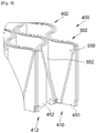
- the figure 4 shows an assembly 400 constituting an acoustic insulator according to a second embodiment of the invention.
- the assembly 400 according to the second embodiment is similar to the assembly 100 according to the first embodiment except in that the hexagonal shapes are replaced by circular shapes.
- the first structure 410 forms a honeycomb structure which comprises a succession of cages 402 each being hollow and having a circular section thus delimiting each a cylindrical cell.
- the first structure 410 consists of a first strip 450 and a second strip 452, which are arranged opposite one another and extend between the first plate and the second plate.
- the first strip 450 is shaped to form half of the wall of said cage 402 which here takes the form of a half-cylinder
- the second strip 452 is shaped to form the other half of the wall of said cage 402 which here takes the form of a half-cylinder.
- junction walls also consist of two sides spaced from each other.
- the junction walls take the form of a cylinder arc.
- the second structure 412 comprises a succession of cones 502 where the base of each cone 502 has a circular section and is positioned between the two strips 450 and 452 of the first structure 412. Each cone 502 forms a cone of revolution.
- the circular base has the same dimensions as the cell to accommodate it.
- the second structure 412 consists of a first strip 550 and a second strip 552, which are arranged opposite one another and extend between the bases and the tops of the cones 502, that is to say between the first plate and the second plate.
- the first strip 550 is shaped to form half of the wall of said cone 502 which here takes the form of a half-cone of revolution
- the second strip 552 is shaped to form the other half of the wall of said cone 502 which here takes the form of a half-cone of revolution.
- the connecting walls take the form of a cylinder arc.
- each first structure 110, 410 comprises a succession of cages 202, 402, each delimiting a cell 205 having a section of a shape (hexagonal, circular, rectangular), and between two neighboring cages 202, 402 , a junction wall 207 consisting of two sides spaced from each other.
- each second structure 112, 412 comprises a succession of cones 302, 502, each having a base and an apex, and between two neighboring cones 302, 502, a connecting wall 307 consisting of two sides, where the base has a section of the same shape as the section of the cells 205.
- each first structure 110, 410 consists of a first strip 250, 450 and a second strip 252, 452 arranged opposite one another and extend between the first plate 102 and the second plate 104, where for each cage 202, 402, the first strip 250, 450 is shaped to form half of the wall of said cage 202, 402 and the second strip 252, 452 is shaped to form the other half of the wall of said cage 202, 402, and where for two successive halves, each strip 250, 252, 450, 452 comprises a section of the junction wall 207 which connects two consecutive halves.
- half of the wall of a cage 202, 402 is made up of three successive sides 204, or of a half-cylinder.
- each second structure 112, 412 consists of a first strip 350, 550 and a second strip 352, 552 arranged opposite one another and extend between the first plate 102 and the second plate 104, where for each cone 302, 502, the first strip 350, 550 is shaped to form half of the wall of said cone 302, 502 and the second strip 352, 552 is shaped to form the other half of the wall of said cone 302, 502, where for each strip 350, 352, 450, 452, at least one of the wall halves of each cone 302, 502 is pierced with a hole 354, and where for two successive halves, each strip 350, 352, 450, 452 comprises a section of the connecting wall 307 which connects two consecutive halves.
- half of the wall of a cone 302, 502 consists of three successive sides 304, or a half-cone of revolution.
- each cone 302, 502 is located in a cell 205 and each connecting wall 307 is located between the two sides of a junction wall 207, and between two first neighboring structures 110, 410, a second structure 112, 412 is also put in place.
Landscapes
- Engineering & Computer Science (AREA)
- Physics & Mathematics (AREA)
- Chemical & Material Sciences (AREA)
- Combustion & Propulsion (AREA)
- Acoustics & Sound (AREA)
- Mechanical Engineering (AREA)
- Multimedia (AREA)
- General Engineering & Computer Science (AREA)
- Architecture (AREA)
- Structural Engineering (AREA)
- Civil Engineering (AREA)
- Electromagnetism (AREA)
- Aviation & Aerospace Engineering (AREA)
- Soundproofing, Sound Blocking, And Sound Damping (AREA)
- Exhaust Silencers (AREA)
Abstract
Description
- La présente invention concerne un assemblage constituant un isolant acoustique, ainsi qu'un procédé de fabrication d'un tel assemblage.
- Lors de son fonctionnement, un moteur d'aéronef génère du bruit. Ce moteur est logé dans une nacelle et pour atténuer ce bruit, il est connu de mettre en place des assemblages constituant un isolant acoustique autour du moteur dans la structure de la nacelle.
- De tels assemblages constituant un isolant acoustique prennent par exemple la forme de structures en nid d'abeilles. Une telle structure en nid d'abeilles comporte deux plaques parallèles dont une est perforée et entre lesquelles sont agencées des cellules hexagonales juxtaposées les unes aux autres.
- On connait de la demande de brevet
EP2960023 , un assemblage comprenant des cônes qui sont insérés individuellement dans des cellules hexagonales d'une structure en nid d'abeille afin de constituer un isolant acoustique qui combine le principe quart d'ondes et un résonateur d'Helmholtz. Dans d'autres applications, comme décrit dans la demande de brevetUS2015/027629 , les cônes sont usinés dans un insert monobloc. - Bien que d'un point de vue acoustique, de tels assemblages donnent de bons résultats, il est souhaitable de trouver un assemblage constituant un isolant acoustique qui permette d'atténuer un certain nombre de fréquences acoustiques et qui soit facile à fabriquer.
- Un objet de la présente invention est de proposer un assemblage constituant un isolant acoustique qui puisse atténuer un certain nombre de fréquences acoustiques et qui soit facile à fabriquer.
- A cet effet, est proposé un assemblage tel que revendiqué dans la revendication 1.
- Un tel assemblage permet d'obtenir une atténuation de plusieurs fréquences acoustiques et est facile à fabriquer.
- Les caractéristiques de l'invention mentionnées ci-dessus, ainsi que d'autres, apparaîtront plus clairement à la lecture de la description suivante d'un exemple de réalisation, ladite description étant faite en relation avec les dessins joints, parmi lesquels :
- La
figure 1 est une vue en perspective d'un assemblage constituant un isolant acoustique selon un premier mode de réalisation de l'invention, - la
figure 2 est une vue en perspective d'une première structure de l'isolant acoustique de lafigure 1 , - la
figure 3 est une vue en perspective d'une deuxième structure de l'isolant acoustique de lafigure 1 , et - la
figure 4 est une vue en perspective d'un assemblage constituant un isolant acoustique selon un deuxième mode de réalisation de l'invention. - En relation avec la
figure 1 , un assemblage 100 constituant un isolant acoustique comporte une première plaque 102 et une deuxième plaque 104 qui sont à distance l'une de l'autre. L'une des plaques, ici la deuxième plaque 104, est percée de trous 106 pour permettre le passage des ondes acoustiques. - Entre la première plaque 102 et la deuxième plaque 104, sont disposées une pluralité de premières structures 110 (détaillées à la
figure 2 ) et une pluralité de deuxièmes structures 112 (détaillées à lafigure 3 ). - La première structure 110 forme une structure en nid d'abeilles qui comporte une succession de cages 202 s'étendant selon une première direction 201, formant une ligne, et dans l'assemblage 100, la première structure 110 se répète selon une deuxième direction 203 perpendiculaire à la première direction 201, formant ainsi des colonnes. Chaque cage 202 est creuse et présente une paroi avec une section hexagonale et à six pans 204 parallèles 2 à 2. Chaque cage 202 délimite une alvéole 205 hexagonale.
- Sur une ligne, chaque cage 202 est rattachée à chaque cage 202 voisine par une paroi de jonction 207 qui est parallèle à la première direction 201. Chaque paroi de jonction 207 de la première structure 110 est double et est donc constituée de deux pans parallèles. Les deux pans de la paroi de jonction 207 sont distants l'un de l'autre pour permettre l'introduction d'une paroi de liaison 307 de la deuxième structure 112 comme cela est expliqué ci-dessous.
- Selon la deuxième direction 203, les cages 202 sont disposées les unes contre les autres en quinconce et deux cages 202 voisines présentent un pan 204 commun. En outre, chaque paroi de jonction 207 d'une ligne forme l'une des pans 204 de la cage 202 de la ligne voisine.
- Les pans 204 et les parois de jonction 207 s'étendent entre une première extrémité 113 solidaire de la première plaque 102 et une deuxième extrémité 114 solidaire de la deuxième plaque 104. Les extrémités 113 et 114 sont fixées à la première plaque 102 et la deuxième plaque 104, par exemple par collage, soudage ou autres.
- Pour une ligne, la première structure 110 est constituée d'une première bande 250 et d'une deuxième bande 252, qui sont disposées en regard l'une de l'autre et s'étendent entre la première plaque 102 et la deuxième plaque 104.
- Pour chaque cage 202, la première bande 250 est conformée pour former la moitié de la paroi de ladite cage 202 sous la forme de trois pans 204 successifs et la deuxième bande 252 est conformée pour former l'autre moitié de la paroi de ladite cage 202 sous la forme de trois autres pans 204 successifs de ladite cage 202.
- Pour deux demi-hexagones successifs, chaque bande 250, 252 comporte un pan de la paroi de jonction 207 qui relie deux demi-hexagones consécutifs.
- La deuxième structure 112 comporte une succession de cônes 302 s'étendant selon la première direction 201 et dans l'assemblage 100, la deuxième structure 112 se répète selon la deuxième direction 203.
- La base de chaque cône 302 a une section hexagonale et se positionne entre les deux bandes 250 et 252 de la première structure 112 au niveau de la deuxième extrémité 114 tandis que le sommet de chaque cône 302 vient en contact avec la première plaque 102. Chaque cône 302 forme un cône hexagonal avec une paroi à six pans 304. La base hexagonale présente les dimensions appropriées à celles de l'alvéole 205 pour pouvoir s'y loger.
- Sur une ligne, chaque cône 302 est séparé de son voisin par une paroi de liaison 307 qui est parallèle à la première direction 201. Chaque paroi de liaison 307 est double et est donc constituée de deux pans parallèles et solidaires.
- Chaque cône 302 se positionne dans une alvéole 205 et la paroi de liaison 307 se positionne entre les pans de la paroi de jonction 207.
- Pour une ligne, la deuxième structure 112 est constituée d'une première bande 350 et d'une deuxième bande 352, qui sont disposées en regard l'une de l'autre et s'étendent entre les bases et les sommets des cônes 302, c'est-à-dire entre la première plaque 102 et la deuxième plaque 104.
- Pour chaque cône 302, la première bande 350 est conformée pour former la moitié de la paroi dudit cône 302 sous la forme de trois pans 304 successifs dudit cône 302 et la deuxième bande 352 est conformée pour former l'autre moitié de la paroi dudit cône 302 sous la forme des trois autres pans 304 successifs dudit cône 302.
- Pour deux demi-cônes successifs, chaque bande 350, 352 comporte un pan de la paroi de liaison 307 qui relie deux demi-cônes consécutifs.
- Pour chaque bande 350, 352, au moins l'une des moitiés de paroi de chaque cône 302 est percée d'un trou 354 pour le passage des ondes acoustiques, c'est-à-dire ici au moins l'un des pans 304.
- Ainsi, sur une ligne selon la première direction 201, dans chaque alvéole 205 de la première structure 110 est disposé un cône 302 de la deuxième structure 112. Comme les parois de liaison 307 se prolongent d'une alvéole 205 à l'autre, le volume entre le cône 302 et la paroi de la cage 202 où ledit cône 302 est logé, est divisé en deux chambres 150 et 152 distinctes.
- En outre, entre deux premières structures 110 voisines selon la deuxième direction 203, une deuxième structure 112 est également mise en place. Les deux premières structures 110 voisines sont espacées l'une de l'autre pour permettre le passage des parois de liaison 307.
- Un tel assemblage 100 constitue ainsi un isolant acoustique qui combine le principe quart d'ondes et un résonateur d'Helmholtz. L'intérieur de chaque cône 302 atténue les hautes fréquences, et les chambres 150 et 152 atténuent les basses fréquences. En outre, il est possible de réaliser des cônes 302 asymétriques de manière à obtenir des chambres 150 et 152 de volumes différents afin d'atténuer deux basses fréquences différentes.
- En outre, un tel assemblage 100 est facile à réaliser.
- Selon les matériaux utilisés, chaque bande 250, 252, 350, 352 peut être réalisée par emboutissage, thermoformage ou pliage, puis fixée par tous moyens appropriés, soudage, collage...
- En outre, les densités et les épaisseurs des bandes 250, 252, 350, 352 peuvent être différentes afin d'avoir un équilibre entre la tenue mécanique de l'assemblage 100 et la souplesse pour le formage pour les bandes.
- Le principe d'assemblage consiste à fixer une première bande 350 de la deuxième structure 112 à une première bande 250 de la première structure 110, puis à fixer une deuxième bande 352 de la deuxième structure 112 à la première bande 350 de la deuxième structure 112 ainsi fixée, puis à fixer une deuxième bande 252 de la première structure 110 à la deuxième bande 352 de la deuxième structure 112 ainsi fixée.
- Le processus se poursuit de la même manière, en considérant que la deuxième bande 252 de la première structure 110 ainsi fixée constitue la première bande 250 de la première structure 110 suivante.
- Le procédé de fabrication et d'assemblage est donc simple et met en œuvre des étapes simples.
- L'ensemble est alors fixé entre la première plaque 102 et la deuxième plaque 104.
- Le procédé de fabrication de l'assemblage 100 comporte ainsi :
- une première étape au cours de laquelle une première bande 350 de la deuxième structure 112 est fixée à une première bande 250 de la première structure 110,
- une deuxième étape au cours de laquelle une deuxième bande 352 de la deuxième structure 112 est fixée à la première bande 350 de la deuxième structure 112 ainsi fixée,
- une troisième étape au cours de laquelle une deuxième bande 252 de la première structure 110 est fixée à la deuxième bande 352 de la deuxième structure 112 ainsi fixée,
- tant qu'une première structure 110 ou une deuxième structure 112 doit être ajoutée, une étape de bouclage sur la première étape en considérant que la deuxième bande 252 de la première structure 110 ainsi fixée constitue la première bande 250 de la première structure 110 suivante,
- une étape au cours de laquelle, les premières et deuxièmes structures 110, 112 ainsi fixées sont fixées entre la première plaque 102 et la deuxième plaque 104.
- Lors de la fixation entre la première plaque 102 et la deuxième plaque 104, les premières extrémités 113 et les sommets des cônes 302 sont fixés à la première plaque 102, et les deuxièmes extrémités 114 et les bases des cônes 302 sont fixées à la deuxième plaque 104.
- Pour prendre en compte la courbure lorsque l'assemblage 100 doit être mis en place contre une partie arquée comme par exemple une entrée d'air, un plug acoustique de tuyère de turbomachine, etc. Les bandes 250, 252, 350 et 352 sont assemblées les unes aux autres directement sur un outillage reprenant la forme arquée correspondant à ladite partie arquée. C'est-à-dire que les bandes sont dans un premier temps conformées en prenant en compte la courbure finale à obtenir, puis elles subissent un formage, et elles sont ensuite fixées les unes aux autres sur l'outillage.
- Lorsqu'il y a un risque de présence de liquides dans l'assemblage 100, les extrémités des bandes 250, 252, 350 et 352 qui se trouvent le plus bas, présentent des perçages 160 et 162 pour permettre le drainage des liquides. Dans le mode de réalisation de l'invention présenté sur les
Figs. 1 à 3 , les perçages 160 et 162 sont au niveau de la première plaque 102, mais dans un autre mode de réalisation où la première plaque 102 serait au-dessus de la deuxième plaque 104, les perçages seraient réalisés au niveau de la deuxième plaque 104. - Les perçages 162, outre leur fonction de passage pour des liquides à drainer, permettent également l'augmentation du volume en faisant communiquer les différents volumes entre eux.
- La
figure 4 montre un assemblage 400 constituant un isolant acoustique selon un deuxième mode de réalisation de l'invention. L'assemblage 400 selon le deuxième mode de réalisation est similaire à l'assemblage 100 selon le premier mode de réalisation sauf en ce que les formes hexagonales sont remplacées par des formes circulaires. - Ainsi, la première structure 410 forme une structure en nid d'abeilles qui comporte une succession de cages 402 chacune étant creuse et présentant une section circulaire délimitant ainsi chacune une alvéole cylindrique. Pour une ligne, la première structure 410 est constituée d'une première bande 450 et d'une deuxième bande 452, qui sont disposées en regard l'une de l'autre et s'étendent entre la première plaque et la deuxième plaque. Pour chaque cage 402, la première bande 450 est conformée pour former la moitié de la paroi de ladite cage 402 qui prend ici la forme d'un demi-cylindre et la deuxième bande 452 est conformée pour former l'autre moitié de la paroi de ladite cage 402 qui prend ici la forme d'un demi-cylindre.
- Les parois de jonction sont également constituées de deux pans distants l'un de l'autre. Dans le deuxième mode de réalisation, les parois de jonction prennent la forme d'arc de cylindre.
- La deuxième structure 412 comporte une succession de cônes 502 où la base de chaque cône 502 a une section circulaire et se positionne entre les deux bandes 450 et 452 de la première structure 412. Chaque cône 502 forme un cône de révolution. La base circulaire présente les mêmes dimensions que l'alvéole pour pouvoir s'y loger.
- Pour une ligne, la deuxième structure 412 est constituée d'une première bande 550 et d'une deuxième bande 552, qui sont disposées en regard l'une de l'autre et s'étendent entre les bases et les sommets des cônes 502, c'est-à-dire entre la première plaque et la deuxième plaque. Pour chaque cône 502, la première bande 550 est conformée pour former la moitié de la paroi dudit cône 502 qui prend ici la forme d'un demi-cône de révolution et la deuxième bande 552 est conformée pour former l'autre moitié de la paroi dudit cône 502 qui prend ici la forme d'un demi-cône de révolution.
- Dans le deuxième mode de réalisation, les parois de liaison prennent la forme d'arc de cylindre.
- Bien sûr, il est également possible de prévoir que les sections circulaires ou hexagonales sont remplacées par des sections rectangulaires.
- Les possibilités d'asymétrie des cônes et de présence des perçages sont applicables à tous les modes de réalisation.
- Ainsi d'une manière générale, chaque première structure 110, 410 comporte une succession de cages 202, 402, chacune délimitant une alvéole 205 présentant une section d'une forme (hexagonale, circulaire, rectangulaire), et entre deux cages 202, 402 voisines, une paroi de jonction 207 constituée de deux pans distants l'un de l'autre.
- D'une manière générale, chaque deuxième structure 112, 412 comporte une succession de cônes 302, 502, chacun présentant une base et un sommet, et entre deux cônes 302, 502 voisins, une paroi de liaison 307 constituée de deux pans, où la base présente une section de la même forme que la section des alvéoles 205.
- D'une manière générale, chaque première structure 110, 410 est constituée d'une première bande 250, 450 et d'une deuxième bande 252, 452 disposées en regard l'une de l'autre et s'étendent entre la première plaque 102 et la deuxième plaque 104, où pour chaque cage 202, 402, la première bande 250, 450 est conformée pour former la moitié de la paroi de ladite cage 202, 402 et la deuxième bande 252, 452 est conformée pour former l'autre moitié de la paroi de ladite cage 202, 402, et où pour deux moitiés successives, chaque bande 250, 252, 450, 452 comporte un pan de la paroi de jonction 207 qui relie deux moitiés consécutives. Selon le cas, la moitié de la paroi d'une cage 202, 402 est constituée de trois pans 204 successifs, ou d'un demi-cylindre.
- D'une manière générale, chaque deuxième structure 112, 412 est constituée d'une première bande 350, 550 et d'une deuxième bande 352, 552 disposées en regard l'une de l'autre et s'étendent entre la première plaque 102 et la deuxième plaque 104, où pour chaque cône 302, 502, la première bande 350, 550 est conformée pour former la moitié de la paroi dudit cône 302, 502 et la deuxième bande 352, 552 est conformée pour former l'autre moitié de la paroi dudit cône 302, 502, où pour chaque bande 350, 352, 450, 452, au moins l'une des moitiés de paroi de chaque cône 302, 502 est percée d'un trou 354, et où pour deux moitiés successives, chaque bande 350, 352, 450, 452 comporte un pan de la paroi de liaison 307 qui relie deux moitiés consécutives. Selon le cas, la moitié de la paroi d'un cône 302, 502 est constituée de trois pans 304 successifs, ou d'un demi-cône de révolution.
- D'une manière générale, chaque cône 302, 502 se trouve dans une alvéole 205 et chaque paroi de liaison 307 se trouve entre les deux pans d'une paroi de jonction 207, et entre deux premières structures 110, 410 voisines, une deuxième structure 112, 412 est également mise en place.
Claims (6)
- Assemblage (100, 400) constituant un isolant acoustique et comportant une première plaque (102), une deuxième plaque (104) percée de trous (106), une pluralité de premières structures (110, 410) disposées les unes à côté des autres selon une deuxième direction (203), et une pluralité de deuxièmes structures (112, 412) disposées les unes à côté des autres selon la deuxième direction (203),
où chaque première structure (110, 410) comporte une succession de cages (202, 402), chacune délimitant une alvéole (205) présentant une section d'une forme, et entre deux cages (202, 402) voisines, une paroi de jonction (207) constituée de deux pans distants l'un de l'autre,
où chaque deuxième structure (112, 412) comporte une succession de cônes (302, 502), chacun présentant une base et un sommet, et entre deux cônes (302, 502) voisins, une paroi de liaison (307) constituée de deux pans, où la base présente une section de la même forme que la section des alvéoles (205),
où chaque première structure (110, 410) est constituée d'une première bande (250, 450) et d'une deuxième bande (252, 452) disposées en regard l'une de l'autre et s'étendent entre la première plaque (102) et la deuxième plaque (104), où pour chaque cage (202, 402), la première bande (250, 450) est conformée pour former la moitié de la paroi de ladite cage (202, 402) et la deuxième bande (252, 452) est conformée pour former l'autre moitié de la paroi de ladite cage (202, 402), et où pour deux moitiés successives, chaque bande (250, 252, 450, 452) comporte un pan de la paroi de jonction (207) qui relie deux moitiés consécutives,
où chaque deuxième structure (112, 412) est constituée d'une première bande (350, 550) et d'une deuxième bande (352, 552) disposées en regard l'une de l'autre et s'étendent entre la première plaque (102) et la deuxième plaque (104), où pour chaque cône (302, 502), la première bande (350, 550) est conformée pour former la moitié de la paroi dudit cône (302, 502) et la deuxième bande (352, 552) est conformée pour former l'autre moitié de la paroi dudit cône (302, 502), où pour chaque bande (350, 352, 450, 452), au moins l'une des moitiés de paroi de chaque cône (302, 502) est percée d'un trou (354), et où pour deux moitiés successives, chaque bande (350, 352, 450, 452) comporte un pan de la paroi de liaison (307) qui relie deux moitiés consécutives,
de manière à ce que chaque cône (302, 502) se trouve dans une alvéole (205) et à ce que chaque paroi de liaison (307) se trouve entre les deux pans d'une paroi de jonction (207), et où entre deux premières structures (110, 410) voisines, une deuxième structure (112, 412) est également mise en place. - Assemblage (100, 400) selon la revendication 1, caractérisé en ce qu'au moins un cône (302, 502) est asymétrique, de manière à ce que les volumes des deux chambres (150, 152) créées entre ledit cône (302, 502) et la paroi de la cage (202, 402) où il est logé soient différents.
- Assemblage (100, 400) selon l'une des revendications 1 ou 2, caractérisé en ce qu'au moins l'une des extrémités des bandes (250, 252, 350, 352, 450, 452, 550, 552) présente des perçages (160, 162).
- Assemblage (100) selon l'une des revendications 1 à 3, caractérisé en ce que la forme est un hexagone, en ce que chaque moitié de paroi d'une cage (202) est constituée de trois pans (204) successifs, et en ce que chaque moitié de la paroi d'un cône (302) est constituée de trois pans (304) successifs.
- Assemblage (400) selon l'une des revendications 1 à 3, caractérisé en ce que la forme est un cercle, en ce que chaque moitié de la paroi d'une cage (402) est constituée d'un demi-cylindre, et en ce que chaque moitié de la paroi d'un cône (502) est constituée d'un demi-cône de révolution.
- Procédé de fabrication d'un assemblage (100) selon l'une des revendications 1 à 3, comportant :- une première étape au cours de laquelle une première bande (350) de la deuxième structure (112) est fixée à une première bande (250) de la première structure (110),- une deuxième étape au cours de laquelle une deuxième bande (352) de la deuxième structure (112) est fixée à la première bande (350) de la deuxième structure (112) ainsi fixée,- une troisième étape au cours de laquelle une deuxième bande (252) de la première structure (110) est fixée à la deuxième bande (352) de la deuxième structure (112) ainsi fixée,- tant qu'une première structure (110) ou une deuxième structure (112) doit être ajoutée, une étape de bouclage sur la première étape en considérant que la deuxième bande (252) de la première structure (110) ainsi fixée constitue la première bande (250) de la première structure (110) suivante,- une étape au cours de laquelle, les premières et deuxièmes structures (110, 112) ainsi fixées sont fixées entre la première plaque (102) et la deuxième plaque (104).
Applications Claiming Priority (1)
| Application Number | Priority Date | Filing Date | Title |
|---|---|---|---|
| FR1871386A FR3088057A1 (fr) | 2018-11-07 | 2018-11-07 | Assemblage constituant un isolant acoustique |
Publications (2)
| Publication Number | Publication Date |
|---|---|
| EP3650332A1 true EP3650332A1 (fr) | 2020-05-13 |
| EP3650332B1 EP3650332B1 (fr) | 2021-01-20 |
Family
ID=67107480
Family Applications (1)
| Application Number | Title | Priority Date | Filing Date |
|---|---|---|---|
| EP19203729.9A Active EP3650332B1 (fr) | 2018-11-07 | 2019-10-17 | Assemblage constituant un isolant acoustique |
Country Status (4)
| Country | Link |
|---|---|
| US (1) | US11348565B2 (fr) |
| EP (1) | EP3650332B1 (fr) |
| CN (1) | CN111156090B (fr) |
| FR (1) | FR3088057A1 (fr) |
Cited By (4)
| Publication number | Priority date | Publication date | Assignee | Title |
|---|---|---|---|---|
| EP4094933A1 (fr) * | 2021-05-27 | 2022-11-30 | Airbus Operations (S.A.S.) | Procédé de fabrication d'une structure alvéolaire obtenue à partir de bandes de matière pliées et structure alvéolaire ainsi obtenue |
| WO2022248790A1 (fr) * | 2021-05-28 | 2022-12-01 | Safran | Panneau de traitement acoustique d'un turboréacteur et son système de drainage |
| FR3129874A1 (fr) * | 2021-12-07 | 2023-06-09 | Airbus Operations (S.A.S.) | Outillage d’assemblage d’une structure alvéolaire, dispositif d’assemblage comprenant ledit outillage et procédé de fabrication d’une structure alvéolaire utilisant ledit outillage |
| US20230252966A1 (en) * | 2020-06-23 | 2023-08-10 | Safran | Acoustic panel and associated manufacturing method |
Families Citing this family (10)
| Publication number | Priority date | Publication date | Assignee | Title |
|---|---|---|---|---|
| FR3088905A1 (fr) * | 2018-11-28 | 2020-05-29 | Airbus Operations (S.A.S.) | Structure d’absorption acoustique comprenant un système de drainage de liquide et ensemble propulsif comportant une telle structure d’absorption acoustique |
| FR3095671B1 (fr) * | 2019-04-30 | 2022-07-29 | Safran Aircraft Engines | Intégration d’un amortisseur de flottement fan dans un carter moteur |
| FR3098143A1 (fr) * | 2019-07-05 | 2021-01-08 | Airbus Operations | Revêtement insonorisant comportant une structure alvéolaire formée de bandes longitudinales formant des résonateurs de Helmholtz et des cavités intermédiaires traitant des plages acoustiques différentes |
| US11339720B2 (en) * | 2020-02-21 | 2022-05-24 | Raytheon Technologies Corporation | Acoustic liner with non-uniform volumetric distribution |
| US11668236B2 (en) * | 2020-07-24 | 2023-06-06 | General Electric Company | Acoustic liners with low-frequency sound wave attenuating features |
| CN113147127A (zh) * | 2020-12-30 | 2021-07-23 | 苏州云逸航空复合材料结构有限公司 | 蜂窝结构 |
| US12548540B2 (en) * | 2021-03-29 | 2026-02-10 | Bae Systems Plc | Acoustic absorbing structures |
| FR3125245B1 (fr) * | 2021-07-15 | 2023-12-29 | Safran | Procédé de fabrication d’un composant à partir de granulés en matériau thermoplastique |
| US20250109586A1 (en) * | 2022-01-14 | 2025-04-03 | University Of Puerto Rico | Scutoidal sub-cell and cell arrangements |
| FR3154531B1 (fr) * | 2023-10-18 | 2026-02-27 | Safran Aircraft Engines | Composant acoustique en une seule pièce avec des cellules acoustiques désalignées |
Citations (7)
| Publication number | Priority date | Publication date | Assignee | Title |
|---|---|---|---|---|
| US3952831A (en) * | 1974-02-26 | 1976-04-27 | Societe Nationale D'etude Et De Construction De Moteurs D'aviation | Composite material with acoustic absorption properties |
| US20100320201A1 (en) * | 2009-06-22 | 2010-12-23 | Paul Dagesse | Tank formed from panels of composite material |
| US8707747B1 (en) * | 2012-12-14 | 2014-04-29 | Rohr, Inc. | Forming a shaped sandwich panel with a die and a pressure vessel |
| US20150027629A1 (en) | 2013-07-29 | 2015-01-29 | The Boeing Company | Septumization of Honeycomb Sandwiches |
| US20150041248A1 (en) * | 2013-08-12 | 2015-02-12 | Hexcel Corporation | Multi-sectional acoustic septum |
| EP2960023A1 (fr) | 2014-06-24 | 2015-12-30 | The Boeing Company | Production automatisée de structures acoustiques |
| FR3026122A1 (fr) * | 2014-09-24 | 2016-03-25 | Snecma | Panneau de traitement acoustique |
Family Cites Families (8)
| Publication number | Priority date | Publication date | Assignee | Title |
|---|---|---|---|---|
| CN102307783B (zh) * | 2009-02-03 | 2014-07-09 | 空中客车运营简化股份公司 | 特别适宜于飞行器发动机舱空气入口的声学处理用的面板 |
| FR2971892A1 (fr) | 2011-02-22 | 2012-08-24 | Souriau | Contact electrique et ensemble connecteur a fort nombre de manoeuvres |
| US9704467B1 (en) * | 2016-04-15 | 2017-07-11 | Rohr, Inc. | Acoustic panel with corrugated baffles and septums |
| US10316755B2 (en) * | 2016-11-18 | 2019-06-11 | Rohr, Inc. | Acoustic panel with sidewall stringers |
| FR3065472B1 (fr) * | 2017-04-25 | 2019-05-03 | Airbus Operations | Panneau pour le traitement acoustique comprenant une structure acoustiquement resistive poreuse comportant des canaux de connexion |
| US10851713B2 (en) * | 2017-08-29 | 2020-12-01 | Mra Systems, Llc. | Acoustic liner having internal structure |
| US10902834B2 (en) * | 2018-02-09 | 2021-01-26 | The Boeing Company | Thermoplastic bonding process for acoustically treated linear facesheets |
| US11059559B2 (en) * | 2018-03-05 | 2021-07-13 | General Electric Company | Acoustic liners with oblique cellular structures |
-
2018
- 2018-11-07 FR FR1871386A patent/FR3088057A1/fr not_active Ceased
-
2019
- 2019-10-17 EP EP19203729.9A patent/EP3650332B1/fr active Active
- 2019-10-28 US US16/664,995 patent/US11348565B2/en active Active
- 2019-11-05 CN CN201911071017.5A patent/CN111156090B/zh active Active
Patent Citations (7)
| Publication number | Priority date | Publication date | Assignee | Title |
|---|---|---|---|---|
| US3952831A (en) * | 1974-02-26 | 1976-04-27 | Societe Nationale D'etude Et De Construction De Moteurs D'aviation | Composite material with acoustic absorption properties |
| US20100320201A1 (en) * | 2009-06-22 | 2010-12-23 | Paul Dagesse | Tank formed from panels of composite material |
| US8707747B1 (en) * | 2012-12-14 | 2014-04-29 | Rohr, Inc. | Forming a shaped sandwich panel with a die and a pressure vessel |
| US20150027629A1 (en) | 2013-07-29 | 2015-01-29 | The Boeing Company | Septumization of Honeycomb Sandwiches |
| US20150041248A1 (en) * | 2013-08-12 | 2015-02-12 | Hexcel Corporation | Multi-sectional acoustic septum |
| EP2960023A1 (fr) | 2014-06-24 | 2015-12-30 | The Boeing Company | Production automatisée de structures acoustiques |
| FR3026122A1 (fr) * | 2014-09-24 | 2016-03-25 | Snecma | Panneau de traitement acoustique |
Cited By (9)
| Publication number | Priority date | Publication date | Assignee | Title |
|---|---|---|---|---|
| US20230252966A1 (en) * | 2020-06-23 | 2023-08-10 | Safran | Acoustic panel and associated manufacturing method |
| US12211477B2 (en) * | 2020-06-23 | 2025-01-28 | Safran | Acoustic panel and associated manufacturing method |
| EP4094933A1 (fr) * | 2021-05-27 | 2022-11-30 | Airbus Operations (S.A.S.) | Procédé de fabrication d'une structure alvéolaire obtenue à partir de bandes de matière pliées et structure alvéolaire ainsi obtenue |
| US11987029B2 (en) | 2021-05-27 | 2024-05-21 | Airbus Operations Sas | Method for manufacturing a cellular structure obtained from bent strips of material, and cellular structure thus obtained |
| WO2022248790A1 (fr) * | 2021-05-28 | 2022-12-01 | Safran | Panneau de traitement acoustique d'un turboréacteur et son système de drainage |
| FR3123385A1 (fr) * | 2021-05-28 | 2022-12-02 | Safran | Panneau de traitement acoustique d’un turboréacteur et son système de drainage |
| FR3129874A1 (fr) * | 2021-12-07 | 2023-06-09 | Airbus Operations (S.A.S.) | Outillage d’assemblage d’une structure alvéolaire, dispositif d’assemblage comprenant ledit outillage et procédé de fabrication d’une structure alvéolaire utilisant ledit outillage |
| EP4194193A1 (fr) * | 2021-12-07 | 2023-06-14 | Airbus Operations (S.A.S.) | Outillage d'assemblage d'une structure alvéolaire, dispositif d'assemblage comprenant ledit outillage et procédé de fabrication d'une structure alvéolaire utilisant ledit outillage |
| US12454104B2 (en) | 2021-12-07 | 2025-10-28 | Airbus Operations Sas | Assembly jig for a cellular structure, assembly device comprising said jig, and method for manufacturing a cellular structure using said jig |
Also Published As
| Publication number | Publication date |
|---|---|
| US11348565B2 (en) | 2022-05-31 |
| CN111156090A (zh) | 2020-05-15 |
| FR3088057A1 (fr) | 2020-05-08 |
| CN111156090B (zh) | 2022-08-05 |
| EP3650332B1 (fr) | 2021-01-20 |
| US20200143786A1 (en) | 2020-05-07 |
Similar Documents
| Publication | Publication Date | Title |
|---|---|---|
| EP3650332B1 (fr) | Assemblage constituant un isolant acoustique | |
| EP3993996B1 (fr) | Revêtement insonorisant comportant une structure alvéolaire | |
| FR3026122B1 (fr) | Panneau de traitement acoustique | |
| EP3718759B1 (fr) | Assemblage constituant un materiau acoustiquement absorbant | |
| FR3082987A1 (fr) | Structure constituant un isolant acoustique | |
| EP3963192B1 (fr) | Intégration d'un amortisseur de flottement du fan dans un carter moteur | |
| EP3395675B1 (fr) | Panneau pour le traitement acoustique comprenant une structure acoustiquement resistive poreuse comportant des canaux de connexion | |
| EP1056529B1 (fr) | Cartouche de filtration, notamment pour moteur a combustion interne | |
| EP3534360B1 (fr) | Revêtement insonorisant comportant une structure alvéolaire à cellules courbes formées de part et d'autre d'une même paroi intérieure | |
| EP3395676B1 (fr) | Panneau pour le traitement acoustique comprenant des alveoles contenant chacune une pluralite de conduits | |
| FR3065570A1 (fr) | Garniture surfacique pour absorption acoustique | |
| FR3088848A1 (fr) | Procédé de fabrication d’un élément acoustique d’une structure d’absorption acoustique à partir d’au moins une feuille de matière | |
| WO2003056268A1 (fr) | Elément de circuit pour échangeur de chaleur, notamment de véhicule automobile et échangeur de chaleur ainsi obtenu | |
| FR3088658A1 (fr) | Structure constituant un isolant acoustique | |
| EP4411726A1 (fr) | Structure alvéolaire d'un panneau d atténuation acoustique comprenant au moins une cloison configurée pour vibrer à une fréquence souhaitée, procédé de fabrication de ladite structure alvéolaire | |
| FR3143169A1 (fr) | Ame alveolaire optimisee et panneau d’attenuation acoustique la comprenant pour une turbomachine d’aeronef | |
| CA3068214C (fr) | Troncon de mat d'eolienne, mat d'eolienne et procede d'assemblage | |
| EP4094933A1 (fr) | Procédé de fabrication d'une structure alvéolaire obtenue à partir de bandes de matière pliées et structure alvéolaire ainsi obtenue | |
| CA3118471C (fr) | Troncon de mat d'eolienne, mat d'eolienne et procede d'assemblage | |
| EP4279261A1 (fr) | Panneau acoustique pour aéronef à large bande de fréquence d'atténuation de bruit combinant deux résonateurs et procédé de fabrication du panneau acoustique | |
| WO2022248790A1 (fr) | Panneau de traitement acoustique d'un turboréacteur et son système de drainage | |
| EP4323629B1 (fr) | Panneau acoustique pour turbomachine | |
| FR3166742A1 (fr) | Ensemble constituant un matériau acoustiquement absorbant | |
| EP3892010B1 (fr) | Piece de rigidification pour caisson d'enceinte acoustique | |
| EP4471919A1 (fr) | Batterie |
Legal Events
| Date | Code | Title | Description |
|---|---|---|---|
| PUAI | Public reference made under article 153(3) epc to a published international application that has entered the european phase |
Free format text: ORIGINAL CODE: 0009012 |
|
| STAA | Information on the status of an ep patent application or granted ep patent |
Free format text: STATUS: REQUEST FOR EXAMINATION WAS MADE |
|
| 17P | Request for examination filed |
Effective date: 20191017 |
|
| AK | Designated contracting states |
Kind code of ref document: A1 Designated state(s): AL AT BE BG CH CY CZ DE DK EE ES FI FR GB GR HR HU IE IS IT LI LT LU LV MC MK MT NL NO PL PT RO RS SE SI SK SM TR |
|
| AX | Request for extension of the european patent |
Extension state: BA ME |
|
| GRAP | Despatch of communication of intention to grant a patent |
Free format text: ORIGINAL CODE: EPIDOSNIGR1 |
|
| STAA | Information on the status of an ep patent application or granted ep patent |
Free format text: STATUS: GRANT OF PATENT IS INTENDED |
|
| RIC1 | Information provided on ipc code assigned before grant |
Ipc: F02C 7/045 20060101ALI20200630BHEP Ipc: G10K 11/168 20060101ALI20200630BHEP Ipc: B32B 3/26 20060101ALI20200630BHEP Ipc: B64C 1/40 20060101AFI20200630BHEP Ipc: F02K 1/82 20060101ALI20200630BHEP Ipc: B64D 33/02 20060101ALN20200630BHEP Ipc: B32B 3/12 20060101ALI20200630BHEP Ipc: E04B 1/86 20060101ALI20200630BHEP Ipc: G10K 11/172 20060101ALI20200630BHEP |
|
| INTG | Intention to grant announced |
Effective date: 20200729 |
|
| RIN1 | Information on inventor provided before grant (corrected) |
Inventor name: CZAPLA, LIONEL Inventor name: RAVISE, FLORIAN |
|
| GRAS | Grant fee paid |
Free format text: ORIGINAL CODE: EPIDOSNIGR3 |
|
| GRAA | (expected) grant |
Free format text: ORIGINAL CODE: 0009210 |
|
| STAA | Information on the status of an ep patent application or granted ep patent |
Free format text: STATUS: THE PATENT HAS BEEN GRANTED |
|
| RBV | Designated contracting states (corrected) |
Designated state(s): AL AT BE BG CH CY CZ DE DK EE ES FI FR GB GR HR HU IE IS IT LI LT LU LV MC MK MT NL NO PL PT RO RS SE SI SK SM TR |
|
| AK | Designated contracting states |
Kind code of ref document: B1 Designated state(s): AL AT BE BG CH CY CZ DE DK EE ES FI FR GB GR HR HU IE IS IT LI LT LU LV MC MK MT NL NO PL PT RO RS SE SI SK SM TR |
|
| REG | Reference to a national code |
Ref country code: GB Ref legal event code: FG4D Free format text: NOT ENGLISH |
|
| REG | Reference to a national code |
Ref country code: CH Ref legal event code: EP |
|
| REG | Reference to a national code |
Ref country code: DE Ref legal event code: R096 Ref document number: 602019002280 Country of ref document: DE |
|
| REG | Reference to a national code |
Ref country code: AT Ref legal event code: REF Ref document number: 1356171 Country of ref document: AT Kind code of ref document: T Effective date: 20210215 |
|
| REG | Reference to a national code |
Ref country code: IE Ref legal event code: FG4D Free format text: LANGUAGE OF EP DOCUMENT: FRENCH |
|
| REG | Reference to a national code |
Ref country code: NL Ref legal event code: MP Effective date: 20210120 |
|
| REG | Reference to a national code |
Ref country code: LT Ref legal event code: MG9D |
|
| REG | Reference to a national code |
Ref country code: AT Ref legal event code: MK05 Ref document number: 1356171 Country of ref document: AT Kind code of ref document: T Effective date: 20210120 |
|
| PG25 | Lapsed in a contracting state [announced via postgrant information from national office to epo] |
Ref country code: PT Free format text: LAPSE BECAUSE OF FAILURE TO SUBMIT A TRANSLATION OF THE DESCRIPTION OR TO PAY THE FEE WITHIN THE PRESCRIBED TIME-LIMIT Effective date: 20210520 Ref country code: NO Free format text: LAPSE BECAUSE OF FAILURE TO SUBMIT A TRANSLATION OF THE DESCRIPTION OR TO PAY THE FEE WITHIN THE PRESCRIBED TIME-LIMIT Effective date: 20210420 Ref country code: LT Free format text: LAPSE BECAUSE OF FAILURE TO SUBMIT A TRANSLATION OF THE DESCRIPTION OR TO PAY THE FEE WITHIN THE PRESCRIBED TIME-LIMIT Effective date: 20210120 Ref country code: FI Free format text: LAPSE BECAUSE OF FAILURE TO SUBMIT A TRANSLATION OF THE DESCRIPTION OR TO PAY THE FEE WITHIN THE PRESCRIBED TIME-LIMIT Effective date: 20210120 Ref country code: GR Free format text: LAPSE BECAUSE OF FAILURE TO SUBMIT A TRANSLATION OF THE DESCRIPTION OR TO PAY THE FEE WITHIN THE PRESCRIBED TIME-LIMIT Effective date: 20210421 Ref country code: HR Free format text: LAPSE BECAUSE OF FAILURE TO SUBMIT A TRANSLATION OF THE DESCRIPTION OR TO PAY THE FEE WITHIN THE PRESCRIBED TIME-LIMIT Effective date: 20210120 Ref country code: BG Free format text: LAPSE BECAUSE OF FAILURE TO SUBMIT A TRANSLATION OF THE DESCRIPTION OR TO PAY THE FEE WITHIN THE PRESCRIBED TIME-LIMIT Effective date: 20210420 |
|
| PG25 | Lapsed in a contracting state [announced via postgrant information from national office to epo] |
Ref country code: AT Free format text: LAPSE BECAUSE OF FAILURE TO SUBMIT A TRANSLATION OF THE DESCRIPTION OR TO PAY THE FEE WITHIN THE PRESCRIBED TIME-LIMIT Effective date: 20210120 Ref country code: LV Free format text: LAPSE BECAUSE OF FAILURE TO SUBMIT A TRANSLATION OF THE DESCRIPTION OR TO PAY THE FEE WITHIN THE PRESCRIBED TIME-LIMIT Effective date: 20210120 Ref country code: PL Free format text: LAPSE BECAUSE OF FAILURE TO SUBMIT A TRANSLATION OF THE DESCRIPTION OR TO PAY THE FEE WITHIN THE PRESCRIBED TIME-LIMIT Effective date: 20210120 Ref country code: RS Free format text: LAPSE BECAUSE OF FAILURE TO SUBMIT A TRANSLATION OF THE DESCRIPTION OR TO PAY THE FEE WITHIN THE PRESCRIBED TIME-LIMIT Effective date: 20210120 Ref country code: SE Free format text: LAPSE BECAUSE OF FAILURE TO SUBMIT A TRANSLATION OF THE DESCRIPTION OR TO PAY THE FEE WITHIN THE PRESCRIBED TIME-LIMIT Effective date: 20210120 |
|
| PG25 | Lapsed in a contracting state [announced via postgrant information from national office to epo] |
Ref country code: IS Free format text: LAPSE BECAUSE OF FAILURE TO SUBMIT A TRANSLATION OF THE DESCRIPTION OR TO PAY THE FEE WITHIN THE PRESCRIBED TIME-LIMIT Effective date: 20210520 |
|
| REG | Reference to a national code |
Ref country code: DE Ref legal event code: R097 Ref document number: 602019002280 Country of ref document: DE |
|
| PG25 | Lapsed in a contracting state [announced via postgrant information from national office to epo] |
Ref country code: EE Free format text: LAPSE BECAUSE OF FAILURE TO SUBMIT A TRANSLATION OF THE DESCRIPTION OR TO PAY THE FEE WITHIN THE PRESCRIBED TIME-LIMIT Effective date: 20210120 Ref country code: CZ Free format text: LAPSE BECAUSE OF FAILURE TO SUBMIT A TRANSLATION OF THE DESCRIPTION OR TO PAY THE FEE WITHIN THE PRESCRIBED TIME-LIMIT Effective date: 20210120 Ref country code: SM Free format text: LAPSE BECAUSE OF FAILURE TO SUBMIT A TRANSLATION OF THE DESCRIPTION OR TO PAY THE FEE WITHIN THE PRESCRIBED TIME-LIMIT Effective date: 20210120 |
|
| PLBE | No opposition filed within time limit |
Free format text: ORIGINAL CODE: 0009261 |
|
| STAA | Information on the status of an ep patent application or granted ep patent |
Free format text: STATUS: NO OPPOSITION FILED WITHIN TIME LIMIT |
|
| PG25 | Lapsed in a contracting state [announced via postgrant information from national office to epo] |
Ref country code: DK Free format text: LAPSE BECAUSE OF FAILURE TO SUBMIT A TRANSLATION OF THE DESCRIPTION OR TO PAY THE FEE WITHIN THE PRESCRIBED TIME-LIMIT Effective date: 20210120 Ref country code: SK Free format text: LAPSE BECAUSE OF FAILURE TO SUBMIT A TRANSLATION OF THE DESCRIPTION OR TO PAY THE FEE WITHIN THE PRESCRIBED TIME-LIMIT Effective date: 20210120 Ref country code: RO Free format text: LAPSE BECAUSE OF FAILURE TO SUBMIT A TRANSLATION OF THE DESCRIPTION OR TO PAY THE FEE WITHIN THE PRESCRIBED TIME-LIMIT Effective date: 20210120 |
|
| 26N | No opposition filed |
Effective date: 20211021 |
|
| PG25 | Lapsed in a contracting state [announced via postgrant information from national office to epo] |
Ref country code: ES Free format text: LAPSE BECAUSE OF FAILURE TO SUBMIT A TRANSLATION OF THE DESCRIPTION OR TO PAY THE FEE WITHIN THE PRESCRIBED TIME-LIMIT Effective date: 20210120 Ref country code: AL Free format text: LAPSE BECAUSE OF FAILURE TO SUBMIT A TRANSLATION OF THE DESCRIPTION OR TO PAY THE FEE WITHIN THE PRESCRIBED TIME-LIMIT Effective date: 20210120 |
|
| PG25 | Lapsed in a contracting state [announced via postgrant information from national office to epo] |
Ref country code: IT Free format text: LAPSE BECAUSE OF FAILURE TO SUBMIT A TRANSLATION OF THE DESCRIPTION OR TO PAY THE FEE WITHIN THE PRESCRIBED TIME-LIMIT Effective date: 20210120 |
|
| PG25 | Lapsed in a contracting state [announced via postgrant information from national office to epo] |
Ref country code: IS Free format text: LAPSE BECAUSE OF FAILURE TO SUBMIT A TRANSLATION OF THE DESCRIPTION OR TO PAY THE FEE WITHIN THE PRESCRIBED TIME-LIMIT Effective date: 20210520 |
|
| REG | Reference to a national code |
Ref country code: BE Ref legal event code: MM Effective date: 20211031 |
|
| PG25 | Lapsed in a contracting state [announced via postgrant information from national office to epo] |
Ref country code: MC Free format text: LAPSE BECAUSE OF FAILURE TO SUBMIT A TRANSLATION OF THE DESCRIPTION OR TO PAY THE FEE WITHIN THE PRESCRIBED TIME-LIMIT Effective date: 20210120 |
|
| PG25 | Lapsed in a contracting state [announced via postgrant information from national office to epo] |
Ref country code: LU Free format text: LAPSE BECAUSE OF NON-PAYMENT OF DUE FEES Effective date: 20211017 Ref country code: BE Free format text: LAPSE BECAUSE OF NON-PAYMENT OF DUE FEES Effective date: 20211031 |
|
| PG25 | Lapsed in a contracting state [announced via postgrant information from national office to epo] |
Ref country code: IE Free format text: LAPSE BECAUSE OF NON-PAYMENT OF DUE FEES Effective date: 20211017 |
|
| REG | Reference to a national code |
Ref country code: CH Ref legal event code: PL |
|
| PG25 | Lapsed in a contracting state [announced via postgrant information from national office to epo] |
Ref country code: NL Free format text: LAPSE BECAUSE OF NON-PAYMENT OF DUE FEES Effective date: 20210120 Ref country code: CY Free format text: LAPSE BECAUSE OF FAILURE TO SUBMIT A TRANSLATION OF THE DESCRIPTION OR TO PAY THE FEE WITHIN THE PRESCRIBED TIME-LIMIT Effective date: 20210120 |
|
| PG25 | Lapsed in a contracting state [announced via postgrant information from national office to epo] |
Ref country code: LI Free format text: LAPSE BECAUSE OF NON-PAYMENT OF DUE FEES Effective date: 20221031 Ref country code: HU Free format text: LAPSE BECAUSE OF FAILURE TO SUBMIT A TRANSLATION OF THE DESCRIPTION OR TO PAY THE FEE WITHIN THE PRESCRIBED TIME-LIMIT; INVALID AB INITIO Effective date: 20191017 Ref country code: CH Free format text: LAPSE BECAUSE OF NON-PAYMENT OF DUE FEES Effective date: 20221031 |
|
| PG25 | Lapsed in a contracting state [announced via postgrant information from national office to epo] |
Ref country code: SI Free format text: LAPSE BECAUSE OF FAILURE TO SUBMIT A TRANSLATION OF THE DESCRIPTION OR TO PAY THE FEE WITHIN THE PRESCRIBED TIME-LIMIT Effective date: 20210120 |
|
| PG25 | Lapsed in a contracting state [announced via postgrant information from national office to epo] |
Ref country code: MK Free format text: LAPSE BECAUSE OF FAILURE TO SUBMIT A TRANSLATION OF THE DESCRIPTION OR TO PAY THE FEE WITHIN THE PRESCRIBED TIME-LIMIT Effective date: 20210120 |
|
| PG25 | Lapsed in a contracting state [announced via postgrant information from national office to epo] |
Ref country code: MT Free format text: LAPSE BECAUSE OF FAILURE TO SUBMIT A TRANSLATION OF THE DESCRIPTION OR TO PAY THE FEE WITHIN THE PRESCRIBED TIME-LIMIT Effective date: 20210120 |
|
| PG25 | Lapsed in a contracting state [announced via postgrant information from national office to epo] |
Ref country code: TR Free format text: LAPSE BECAUSE OF FAILURE TO SUBMIT A TRANSLATION OF THE DESCRIPTION OR TO PAY THE FEE WITHIN THE PRESCRIBED TIME-LIMIT Effective date: 20210120 |
|
| PGFP | Annual fee paid to national office [announced via postgrant information from national office to epo] |
Ref country code: DE Payment date: 20251021 Year of fee payment: 7 |
|
| PGFP | Annual fee paid to national office [announced via postgrant information from national office to epo] |
Ref country code: GB Payment date: 20251022 Year of fee payment: 7 |
|
| PGFP | Annual fee paid to national office [announced via postgrant information from national office to epo] |
Ref country code: FR Payment date: 20251030 Year of fee payment: 7 |