EP3650078A1 - Filtered feedthrough assembly for use in implantable medical device and method of manufacturing the same - Google Patents
Filtered feedthrough assembly for use in implantable medical device and method of manufacturing the same Download PDFInfo
- Publication number
- EP3650078A1 EP3650078A1 EP19207769.1A EP19207769A EP3650078A1 EP 3650078 A1 EP3650078 A1 EP 3650078A1 EP 19207769 A EP19207769 A EP 19207769A EP 3650078 A1 EP3650078 A1 EP 3650078A1
- Authority
- EP
- European Patent Office
- Prior art keywords
- feedthrough
- flange
- conductive
- capacitor
- epoxy
- Prior art date
- Legal status (The legal status is an assumption and is not a legal conclusion. Google has not performed a legal analysis and makes no representation as to the accuracy of the status listed.)
- Granted
Links
Images






Classifications
-
- A—HUMAN NECESSITIES
- A61—MEDICAL OR VETERINARY SCIENCE; HYGIENE
- A61N—ELECTROTHERAPY; MAGNETOTHERAPY; RADIATION THERAPY; ULTRASOUND THERAPY
- A61N1/00—Electrotherapy; Circuits therefor
- A61N1/18—Applying electric currents by contact electrodes
- A61N1/32—Applying electric currents by contact electrodes alternating or intermittent currents
- A61N1/36—Applying electric currents by contact electrodes alternating or intermittent currents for stimulation
- A61N1/372—Arrangements in connection with the implantation of stimulators
- A61N1/375—Constructional arrangements, e.g. casings
- A61N1/3752—Details of casing-lead connections
- A61N1/3754—Feedthroughs
-
- A—HUMAN NECESSITIES
- A61—MEDICAL OR VETERINARY SCIENCE; HYGIENE
- A61N—ELECTROTHERAPY; MAGNETOTHERAPY; RADIATION THERAPY; ULTRASOUND THERAPY
- A61N1/00—Electrotherapy; Circuits therefor
- A61N1/18—Applying electric currents by contact electrodes
- A61N1/32—Applying electric currents by contact electrodes alternating or intermittent currents
- A61N1/36—Applying electric currents by contact electrodes alternating or intermittent currents for stimulation
- A61N1/372—Arrangements in connection with the implantation of stimulators
- A61N1/375—Constructional arrangements, e.g. casings
- A61N1/37512—Pacemakers
-
- H—ELECTRICITY
- H01—ELECTRIC ELEMENTS
- H01G—CAPACITORS; CAPACITORS, RECTIFIERS, DETECTORS, SWITCHING DEVICES, LIGHT-SENSITIVE OR TEMPERATURE-SENSITIVE DEVICES OF THE ELECTROLYTIC TYPE
- H01G4/00—Fixed capacitors; Processes of their manufacture
- H01G4/002—Details
- H01G4/224—Housing; Encapsulation
-
- H—ELECTRICITY
- H01—ELECTRIC ELEMENTS
- H01G—CAPACITORS; CAPACITORS, RECTIFIERS, DETECTORS, SWITCHING DEVICES, LIGHT-SENSITIVE OR TEMPERATURE-SENSITIVE DEVICES OF THE ELECTROLYTIC TYPE
- H01G4/00—Fixed capacitors; Processes of their manufacture
- H01G4/002—Details
- H01G4/228—Terminals
- H01G4/236—Terminals leading through the housing, i.e. lead-through
-
- H—ELECTRICITY
- H01—ELECTRIC ELEMENTS
- H01G—CAPACITORS; CAPACITORS, RECTIFIERS, DETECTORS, SWITCHING DEVICES, LIGHT-SENSITIVE OR TEMPERATURE-SENSITIVE DEVICES OF THE ELECTROLYTIC TYPE
- H01G4/00—Fixed capacitors; Processes of their manufacture
- H01G4/35—Feed-through capacitors or anti-noise capacitors
-
- H—ELECTRICITY
- H01—ELECTRIC ELEMENTS
- H01G—CAPACITORS; CAPACITORS, RECTIFIERS, DETECTORS, SWITCHING DEVICES, LIGHT-SENSITIVE OR TEMPERATURE-SENSITIVE DEVICES OF THE ELECTROLYTIC TYPE
- H01G4/00—Fixed capacitors; Processes of their manufacture
- H01G4/38—Multiple capacitors, i.e. structural combinations of fixed capacitors
-
- A—HUMAN NECESSITIES
- A61—MEDICAL OR VETERINARY SCIENCE; HYGIENE
- A61N—ELECTROTHERAPY; MAGNETOTHERAPY; RADIATION THERAPY; ULTRASOUND THERAPY
- A61N1/00—Electrotherapy; Circuits therefor
- A61N1/18—Applying electric currents by contact electrodes
- A61N1/32—Applying electric currents by contact electrodes alternating or intermittent currents
- A61N1/36—Applying electric currents by contact electrodes alternating or intermittent currents for stimulation
- A61N1/362—Heart stimulators
- A61N1/37—Monitoring; Protecting
- A61N1/3718—Monitoring of or protection against external electromagnetic fields or currents
-
- H—ELECTRICITY
- H01—ELECTRIC ELEMENTS
- H01G—CAPACITORS; CAPACITORS, RECTIFIERS, DETECTORS, SWITCHING DEVICES, LIGHT-SENSITIVE OR TEMPERATURE-SENSITIVE DEVICES OF THE ELECTROLYTIC TYPE
- H01G4/00—Fixed capacitors; Processes of their manufacture
- H01G4/30—Stacked capacitors
Definitions
- the present disclosure is directed to feedthrough filter assemblies for use in implantable medical devices such as, for example, cardiac rhythm management and pacemaker devices. More specifically, the present disclosure is directed to the attachment and grounding of capacitors in feedthrough filter assemblies.
- Implantable pulse generators including cardiovascular implantable electronic devices (“CIED”) such as pacemakers and implantable cardioverter defibrillators (“ICD”), are used to provide therapy to cardiac tissue, nerves and other tissue via implantable leads.
- An implantable pulse generator feedthrough or feedthru is used for an electrical pathway extending between the electrically conductive lead securing components of a header of the pulse generator and the electrical components, such as an output flex, hybrid, etc., hermetically sealed in the housing or can of the pulse generator.
- Feedthroughs provide insulated passageways for feedthrough wires, such as palladium/iridium (Pd/Ir) wires, through the wall of the can.
- the header ends of the feedthrough wires are electrically connected to connector blocks that mechanically and electrically couple with proximal connector ends of implantable leads, and the can ends of the feedthrough wires are electrically connected to the electrical components housed in the can of the pulse generator such as the Hybrid Board.
- Implantable pulse generators may include electromagnetic interference ("EMI") filters for filtering out unwanted EMI signals interfering with the signals from the lead wires.
- EMI electromagnetic interference
- the EMI filter is a capacitor that is sandwiched between the feedthrough and the board.
- the capacitors are built as monolithic structures that are internally grounded to a flange of the feedthrough assembly.
- Past attempts at grounding the capacitor to the flange relied on the gold within the braze joint between the insulator and flange to also contact the capacitor and thus provide a conductive path for grounding. This type of grounding can be highly variable depending on the quality of the brazing and the gold mixture within the braze joint.
- a very thin gold strip between the insulator and the flange may provide excessive resistivity, making the ground unusable in the context of implantable pulse generators.
- Other problems of relying on the braze material for grounding purposes include the potential for braze failures, for example caused by mechanical strain on the feedthrough assembly and thermal stressing of the braze material.
- the filtered feedthrough assembly may include: a flange; a plurality of feedthrough wires, a ceramic insulator; an EMI filter; a first non-conductive washer; first and second non-conductive epoxies; and an electrically conductive material.
- the flange is made of an electrically conductive material and includes a can side, a header side, a can side face, and a feedthrough port having an inner surface and extending through the flange from the can side to the header side.
- the plurality of feedthrough wires may extend through the feedthrough port.
- the ceramic insulator may include an outer surface and a plurality of ports extending there through, each of the plurality of ports including a counter bore, the outer surface of the ceramic insulator gold brazed to the inner surface of the first feedthrough port of the flange at a first braze joint.
- the plurality of feedthrough wires respectively extend through and are gold brazed to the first plurality of ports of the first ceramic insulator at second braze joints.
- the EMI filter may include a capacitor having a plurality of ports extending there through.
- the plurality of feedthrough wires respectively extend through the plurality of ports of the capacitor.
- the first non-conductive washer may be positioned between the ceramic insulator and the capacitor.
- the first non-conductive epoxy may cover the first braze joint around a periphery of the outer surface of the ceramic insulator so as to insulate the first braze joint from the capacitor.
- the second non-conductive epoxy may be positioned within the counter bores of the plurality of ports of the ceramic insulator so as to insulate the second braze joint from the capacitor.
- the electrically conductive material may couple and provide a ground from the capacitor to the flange.
- the electrically conductive material includes silver epoxy.
- the electrically conductive material is coupled to the can side face of the flange.
- the electrically conductive material is coupled to the can side face in two strands adjacent long edges of the feedthrough port of the flange.
- the can side face includes a sand blasted surface coupled to the electrically conductive material.
- the filtered feedthrough assembly may further include a polyimide film disc washer positioned between the first non-conductive washer and the capacitor.
- the polyimide film disc washer is made of KAPTON®.
- the filtered feedthrough assembly may further include a second non-conductive washer positioned on the capacitor opposite the first non-conductive washer.
- the filtered feedthrough assembly may further include a conductive silver epoxy bonding the plurality of feedthrough wires and the plurality of ports of the capacitor.
- an implantable pulse generator including: a header; a can; and a filtered feedthrough assembly.
- the header may include lead connector blocks.
- the can may be coupled to the header and include a wall and an electronic substrate housed within the wall.
- the filtered feedthrough assembly may include a flange mounted to the wall of the can and having a feedthrough port, a plurality of feedthrough wires extending through the feedthrough port and electrically connecting the lead connector blocks and the electronic substrate, an insulator brazed to the feedthrough port of the flange at a first braze joint and brazed to the plurality of feedthrough wires at second braze joints, a capacitor having the plurality of feedthrough wires extending there through, a first non-conductive epoxy insulating the first braze joint from electrical connection with the capacitor, a second non-conductive epoxy insulating the second braze joints from electric connection with the capacitor, and an electrically conductive material adhered to the capacitor and the flange for grounding of the capacitor.
- the filtered feedthrough assembly may further include a non-conductive washer positioned between the insulator and the capacitor.
- the filtered feedthrough assembly may further include a polyimide film disc washer positioned between the non-conductive washer and the capacitor.
- the non-conductive washer includes an electrically non-conductive double-sided adhesive.
- the electrically conductive material couples to a portion of a face of the flange.
- the portion of the face of the flange is a soda blasted portion of the flange.
- the electrically conductive material includes a conductive silver epoxy.
- aspects of the present disclosure may include a method of manufacturing a filtered feedthrough assembly for use with an implantable medical device.
- the method may include gold brazing an insulator to a flange at first braze joint.
- the method may additionally include gold brazing a plurality of feedthrough wire to the insulator at second braze joints.
- the method may additionally include applying a first non-conductive epoxy to the first braze joint.
- the method may additionally include applying a second non-conductive epoxy to the second braze joint.
- the method may additionally include grit blasting a face of the flange, applying a conductive epoxy to the face of the flange, and attaching an EMI filter to the conductive epoxy such that it is grounded to the flange via the conductive epoxy and not via the first braze joint or the second braze joints.
- the method may further include attaching a non-conductive washer between the insulator and the EMI filter.
- the method may further include positioning a polyimide film disc washer between the non-conductive washer and the EMI filter.
- the method may further include electrically coupling the EMI filter and the plurality of feedthrough wires using conductive silver epoxy.
- the present disclosure describes a filtered feedthrough assembly of an implantable pulse generator such as, for example, a pacemaker or an ICD.
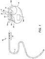
- an implantable pulse generator 5 that utilizes a feedthrough assembly coupled to a filter (e.g., capacitor) and an inline array feedthrough board, reference is first made to FIG. 1 .
- FIG. 1 is a side view of a pulse generator 5 and an implantable lead 7 positioned to be coupled to the pulse generator.
- the pulse generator 5 includes a header 10 and a can or housing 15.
- the header 10 includes connector blocks 20 and a molded portion 25 that encloses the connector blocks 20.
- Each connector block 20 includes an opening 35 configured to receive therein and mate with a connector end 40 of a proximal end 45 of an implantable lead 7, thereby forming an electrical connection between the connector block 20 and the lead connector end 40 and mechanically securing the proximal end 45 of the lead 7 to the header 10 of the pulse generator 5.
- the molded header portion 25 may be formed of a polymer material or epoxy. Passages 50 extend from the exterior of the molded portion 25 to the openings 35 in the connector blocks 20 provide a pathway for the lead distal ends 40 to pass through the molded portion 25 and enter the openings 35.
- the feedthrough assembly 100 provides an electrical connection between the fixed electrical components 102 within the can 15 and the releasable connection with the connector ends 40 of the proximal end 45 of the lead 7.
- the can 15 provides a hermetically sealed enclosure for the pulse generator's electronic components (e.g., hybrid, or various other electronic components), which are mounted on, and electrically interconnected via, an electronic substrate, all of which are housed within the can 15.
- the feedthrough assembly 100 may be a filtered feedthrough assembly 100 with the addition of a filtering component, such as an EMI filter.
- the filtering component may be other types of filters without limitation.
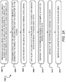
- FIG. 2A is a flowchart of exemplary steps of a method 1000 of manufacturing the filtered feedthrough assembly 100.
- the method 1000 includes providing an unfiltered feedthrough assembly 100 including a flange 110 and an insulator 118, with a series of feedthrough wires 104 extending through the assembly 100.
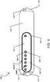
- FIG. 3 depicts a top or can side view of a flange 110 and insulator 118 in the midst of a manufacturing process to become a filtered feedthrough assembly 100.
- the can side is the side of the filtered feedthrough assembly 100 that leads to the can, as opposed to a header side of the assembly.
- the feedthrough assembly 100 includes feedthrough wires 104 that extend from the can side to the header side of the assembly 100.
- the feedthrough wires 104 may be made of gold, palladium, platinum, nickel, titanium, MP35N, niobium, or any other suitable conductive material.
- the flange 110 of the filtered feedthrough assembly 100 includes an elongated body and a feedthrough port 112 through which the feedthrough wires 104 extend. While the present disclosure describes a single feedthrough port 112, the description herein is applicable to a feedthrough assembly 100 having additional feedthrough ports 112, for example two feedthrough ports 112. As seen in the figure, the port 112 is an elongated rectangular port having rounded ends that extend through the flange 110 from the can side to the header side. And as seen in FIG. 3 , seven feedthrough wires 104 extend through the feedthrough port 112 of the flange 110 and the insulator 118.
- the filtered feedthrough assembly 100 includes two ground pins 114 that may be electrically connected with the internal electronics 102 (not seen in FIG. 3 ) on the inside of the can 15 (not seen in FIG. 3 ). As seen in FIG. 3 , each of the ground pins 114 may terminate at a projection 116 that juts out from the elongated body of the flange 110.
- the flange 110 is formed of an electrically conductive material, and therefore provides a conductive path between the ground pins and the can 15 within which the flange 110 is disposed.
- the feedthrough wires 104 are isolated from contact with each other and the flange 110 by a ceramic insulator 118 that is sized to fit within the feedthrough port 112 of the flange 110.
- the ceramic insulator 118 (generally referred to as an insulator) is formed of a non-conducting material and includes a series of wire ports 120 for the feedthrough wires 104 to extend through.
- the ceramic insulator 118 includes an outer surface 122 sized just smaller than the feedthrough port 112. In this instance, the ceramic insulator 118 includes seven wire ports 120 to accommodate the seven feedthrough wires 104.
- the outer surface 122 of the ceramic insulator 118 is brazed to the inner surface of the feedthrough port 112 of the flange 110 at a braze joint 115OD using gold, nickel, platinum, or other suitable material as the braze material.
- This braze joint 115OD may be referred to as "OD gold", meaning the outer diameter of the insulator 118 is gold brazed to the flange 110.
- the ceramic insulator 118 may be coupled to the flange via soldering, welding, or other suitable methods.
- the feedthrough wires 104 may also be connected to the ports 120 of the ceramic insulators 118 via brazing at a braze joint 115ID, which may be referred to as "ID gold", meaning the inner diameter of the ports 120 are gold brazed to the wires 104.
- a braze joint 115ID which may be referred to as "ID gold”
- Alternatives to brazing may include soldering, welding, or other suitable joining methods. These methods help ensure a hermetic seal through the filtered feedthrough assembly 100.
- step 1004 of the method 1000 may include dispensing epoxy 150OD, 150ID on the ceramic insulator 118 of the feedthrough assembly 110 at the braze joints 115OD, 115ID, as illustrated in FIG. 4.
- FIG. 4 depicts a can side view of the filtered feedthrough assembly 100 with a coat of epoxy 150ID, 150OD over the braze joints 115ID, 115OD.
- the epoxy 150ID, 150OD may be a UV curable epoxy. UV curable epoxies do not require the addition of curing agents, and begin to cure with the application of UV light. As seen in FIG.
- the epoxy 150ID, 150OD covers all gold braze material on the feedthrough assembly 100, including the gold braze 115ID coupling the feedthrough wires 104 and the feedthrough ports 120 of the ceramic insulator 118, and the gold braze 115OD coupling the outer surface 122 of the ceramic insulator and the inner surface of the port 112 of the flange 110.
- an EMI filter that is coupled to the flange 110 will not contact the gold braze joints 115ID, 115OD.
- the gold braze joints 115ID, 115OD will not ground the EMI filter and the gold joint 115ID will not contact the silver epoxy 160 illustrated in FIG. 9 and described with reference to step 1028 of the method 1000 of FIG. 2B . This avoids the pitfalls of relying on such a connection as described in the Background section of this application.
- step 1006 of the method 1000 of FIG. 2A may include curing the epoxy 150ID, 150OD. This may include curing the epoxy 150ID, 150OD with ultraviolet light, followed by a thermal oven cure of the epoxy 150ID, 150OD.
- step 1008 of the method 1000 of FIG. 2A may include grit blasting at least a portion of the can side face of the flange 110 (up to and including substantially all of the can side face of the flange 110), for example, with baking soda to remove an oxide layer (e.g., a titanium oxide layer when the flange 110 is formed from titanium) so as to reduce surface oxidation.
- an oxide layer e.g., a titanium oxide layer when the flange 110 is formed from titanium
- Other methods for removing oxide may be performed without limitation. For example, plasma etching and/or acid etching may be utilized to remove oxide.
- the parts may then be placed in a parts fixture and ultrasonically cleaned in a hot de-ionized water bath (which, in certain implementations and without limitation, may be approximately 85 degrees Celsius), at step 1010.
- the feedthrough filter 100 may then be dried in an oven, at step 1012.
- the method 1000 of FIG. 2A may include dispensing conductive silver epoxy 152 on the soda blasted face 111 of the flange 110.
- FIG. 5 depicts the can side of the feedthrough assembly 100 with silver epoxy 152 dispensed or applied to the face 111 of the flange 110.
- the silver epoxy 152 may be dispensed as single continuous strands; however, in other implementations, the silver epoxy 152 may be dispensed as multiple strands or beads.
- the strands of silver epoxy 152 are positioned between the long edges of the feedthrough ports 112 of the flange 110 and the top and bottom edges of the flange 110. As seen in FIG. 5 , the entire face 111 of the can side of the flange 110 appears textured from the soda blasting to remove the titanium oxide layer.
- step 1016 of the method 1000 is shown in FIG. 2B .
- step 1018 of the method 1000 in FIG. 2B includes attaching an optional, but preferred non-conductive adhesive washer 154 to the ceramic insulator 118.
- FIG. 6 illustrates the non-conductive adhesive washer 154 including a plurality of through-holes that are sized and spaced-apart to fit over the feedthrough wires 104.
- the shape of the non-conductive adhesive washer 154 also substantially matches that of the ceramic insulator 118, except that the ceramic insulator may be longer. As seen in FIG. 6 , one or more of the feedthrough wires 104 may not extend through the non-conductive adhesive washer 154.
- the washers 156 are applied to the feedthrough wires 104 that extend through the non-conductive adhesive washer 154, at step 1020 of FIG. 2B .
- the washers 156 may be formed from KAPTON® or a similar insulative or non-conductive material, such as polyimide material, e.g., in the form of polyimide film disc washers 156. The washers 156 are placed on top of the non-conductive adhesive washer 154, as seen in FIG. 7 .
- step 1022 of the method 1000 of FIG. 2B includes attaching an EMI filter (e.g., capacitor) 158 having a plurality of through-holes 160 to the non-conductive adhesive washer 154 by receiving the feedthrough wires 104 of the feedthrough assembly 100 within the plurality of through-holes 160 of the EMI filter 158.
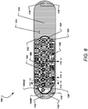
- FIG. 8 shows the EMI filter 158 attached to the flange 110 via the conductive silver epoxy 152 on the face 111 of the flange 110.
- the EMI filter 158 must be grounded in order to function properly.
- the EMI filter 158 is electrically coupled to the flange 110 via the conductive silver epoxy 152. In this way, the EMI filter 158 is grounded by the conductive silver epoxy 152 and avoids all potentially variable contact areas associated with the gold brazing that is insulated via the non-conducting epoxy 150ID, 150OD.
- Additional conductive silver epoxy 168 may be applied to the face 111 of the flange 110 adjacent the conductive silver epoxy 152, as seen in FIG. 12 .
- the conductive silver epoxy 168 may extend onto one or both of the side surfaces of the EMI filter 158 and the flange 110 so as to increase the surface area for grounding of the EMI filter 158 to the flange 110.
- the joint between the two components may be filled with the conductive silver epoxy 168 to form a radiused, smooth joint surface.
- Utilizing the opposing surfaces between the EMI filter 158 and the flange 110 in addition to the side surfaces of the EMI filter 158 and the flange 110 can greatly increase the surface area for grounding as compared to the former methods of relying on the braze joint between the insulator and flange to also contact the capacitor and thus provide a conductive path for grounding.
- the addition of the conductive silver epoxy 168 may be disregarded in favor of utilizing the previously applied conductive silver epoxy 152 described previously.
- FIG. 9 illustrates a cross-sectional view of the filtered feedthrough assembly 100 along the cross-sectional line indicated in FIG. 8 .
- FIG. 9 shows three feedthrough wires 104 extending through the EMI filter 158 and the ceramic insulator 118.
- the UV curable epoxy 150ID is located in the counter bore 162 of the insulator 118.
- the non-conductive adhesive washer 154 Just above the insulator 118 is the non-conductive adhesive washer 154, and then the washers 156, which surround the feedthrough wires 104.
- the non-conductive epoxy 150ID in the counter bore 162 of the insulator completely isolates the gold braze 115ID adhered to the wires 104 within the insulator 118.
- the EMI filter 158 is not in electrical contact with the gold braze 115ID. Instead, the EMI filter 158 is in electrical contact with the feedthrough wires 104 through the conductive silver epoxy 152, as shown in FIG. 8 . Similarly, the EMI filter 158 is grounded to the face 111 of the flange 110 using the conductive silver epoxy 152 and, in certain instances, the additional conductive silver epoxy 168 applied at the outer joint between the EMI filter 158 and the flange 110.
- step 1024 of the method 1000 of FIG. 2B includes thermally curing filtered feedthrough assembly 100 with the EMI filter 158 attached to the flange 110.
- a top mask e.g., single sided removable adhesive
- conductive silver epoxy 164 may be dispensed into the via holes 160 of the EMI filter 158.
- FIG. 10 which is a cross-sectional view of one of the wires 104 of FIG. 9 , conductive silver epoxy 164 is dispensed into the via hole 160 of the EMI filter 158.
- the assembly 100 may be put in a centrifuge and spun in order to allow the conductive silver epoxy 164 to settle in the via holes 160.
- This step 1030 is reflected in the method 1000 of FIG. 2C .
- the steps 1028 and 1030 may be repeated as necessary until the epoxy 164 fully fills the via holes 160 of the EMI filter 158.
- the epoxy 164 may be thermally cured in an oven, at step 1032 of FIG. 2C .
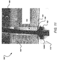
- FIG. 11 which is a cross-sectional view of the wire 104 in FIG. 10 , shows the epoxy 164 fully filled in the via holes 160 of the EMI filter 158, and fully cured.
- the top surface of the EMI filter 158 may be cleaned using a blasting medium (e.g., soda blasting) to remove any excess cured conductive silver epoxy 164, as seen in step 1034 of FIG. 2C .
- a blasting medium e.g., soda blasting
- the filtered feedthrough assembly 100 may be cleaned in an ultrasonic bath using hot de-ionized water, as seen in step 1036 of FIG. 2C .
- the assembly 100 may be dried in an oven, as seen in step 1038 of FIG. 2C .
- a top non-conductive adhesive washer e.g., single sided adhesive
- the entire assembly 100 may then be cured in the oven, as seen in step 1042 of FIG. 2C . And, once curing is complete, the filtered feedthrough assembly 100 may be electrically tested, at step 1044 of FIG. 2C .
- a non-conductive material may be dispensed and coated to the top surface of the EMI filter 158.
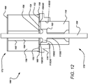
- FIG. 12 is a cross-sectional side view of a filtered feedthrough assembly 100 taken along the section line from FIG. 8 .
- the assembly 100 in FIG. 12 is fully assembled, having completed all the steps of the method 1000 of FIGS. 2A-2C .
- the filtered feedthrough assembly 100 has a header side 170 and a can side 172.
- the feedthrough wires 104 (only a single wire is seen in this cross-sectional view) extend fully through the assembly 100 to connect the electrical components of the can with the lead blocks or other components disposed within the header.
- the non-conductive adhesive 166 is adhered to the top of the EMI filter 158.
- the EMI filter 158 has a plurality of via holes or feedthrough ports 160.
- the via holes 160 are filled with conductive silver epoxy 164 so as to be electrically conductive with the EMI filter 158 and the wire 104.
- a washer 156 (e.g., a KAPTON® washer) surrounds the wire 104.
- the bottom of the EMI filter 158 is adhered to a non-conductive adhesive washer 154.
- To the sides of the adhesive washer 154 is the UV curable epoxy 150OD that insulates the gold braze joint 115OD from contact with the EMI filter 158.
- the UV curable epoxy 150OD surrounds the insulator 118 above the gold braze joint 115OD.
- Additional UV curable epoxy 150ID is dispensed in the counter bore 162 of the insulator 118 so as to partially fill up the counter bore 162 and seal against the wire 104.
- the epoxy 150ID insulates the components from the gold braze joint 115ID in the through-hole of the insulator 118.
- the conductive silver epoxies 152, 168 electrically connect the EMI filter 158 and the face 111 of the flange 110. This electrical connection serves as a ground path for the EMI filter 158. In this way, the potentially variable grounding path from the EMI filter 158 through the braze joints 115ID, 115OD is avoided by insulating all such areas with non-conductive epoxy 150ID, 150OD.
Landscapes
- Engineering & Computer Science (AREA)
- Power Engineering (AREA)
- Health & Medical Sciences (AREA)
- Life Sciences & Earth Sciences (AREA)
- General Health & Medical Sciences (AREA)
- Nuclear Medicine, Radiotherapy & Molecular Imaging (AREA)
- Radiology & Medical Imaging (AREA)
- Animal Behavior & Ethology (AREA)
- Public Health (AREA)
- Veterinary Medicine (AREA)
- Biomedical Technology (AREA)
- Microelectronics & Electronic Packaging (AREA)
- Manufacturing & Machinery (AREA)
- Heart & Thoracic Surgery (AREA)
- Biophysics (AREA)
- Physics & Mathematics (AREA)
- Electromagnetism (AREA)
- Cardiology (AREA)
- Filters And Equalizers (AREA)
- Fixed Capacitors And Capacitor Manufacturing Machines (AREA)
- Electrotherapy Devices (AREA)
Abstract
Description
- The present disclosure is directed to feedthrough filter assemblies for use in implantable medical devices such as, for example, cardiac rhythm management and pacemaker devices. More specifically, the present disclosure is directed to the attachment and grounding of capacitors in feedthrough filter assemblies.
- Implantable pulse generators, including cardiovascular implantable electronic devices ("CIED") such as pacemakers and implantable cardioverter defibrillators ("ICD"), are used to provide therapy to cardiac tissue, nerves and other tissue via implantable leads. An implantable pulse generator feedthrough or feedthru is used for an electrical pathway extending between the electrically conductive lead securing components of a header of the pulse generator and the electrical components, such as an output flex, hybrid, etc., hermetically sealed in the housing or can of the pulse generator.
- Feedthroughs provide insulated passageways for feedthrough wires, such as palladium/iridium (Pd/Ir) wires, through the wall of the can. The header ends of the feedthrough wires are electrically connected to connector blocks that mechanically and electrically couple with proximal connector ends of implantable leads, and the can ends of the feedthrough wires are electrically connected to the electrical components housed in the can of the pulse generator such as the Hybrid Board.
- Implantable pulse generators may include electromagnetic interference ("EMI") filters for filtering out unwanted EMI signals interfering with the signals from the lead wires. Conventionally, the EMI filter is a capacitor that is sandwiched between the feedthrough and the board. The capacitors are built as monolithic structures that are internally grounded to a flange of the feedthrough assembly. Past attempts at grounding the capacitor to the flange relied on the gold within the braze joint between the insulator and flange to also contact the capacitor and thus provide a conductive path for grounding. This type of grounding can be highly variable depending on the quality of the brazing and the gold mixture within the braze joint. For example, a very thin gold strip between the insulator and the flange may provide excessive resistivity, making the ground unusable in the context of implantable pulse generators. Other problems of relying on the braze material for grounding purposes include the potential for braze failures, for example caused by mechanical strain on the feedthrough assembly and thermal stressing of the braze material.
- Accordingly, there is a need in the art for filtered feedthrough assemblies and implantable pulse generators with filtered feedthrough assemblies that are internally grounded that do not rely on grounding through braze material so that improved reliability of the implantable pulse generator is achieved when exposed to interferences, such as Electrical Magnetic Interference.
- The present invention is defined in the independent claims. Further embodiments of the invention are defined in the dependent claims.
- Aspects of the present disclosure may include a filtered feedthrough assembly for an implantable pulse generator. The filtered feedthrough assembly may include: a flange; a plurality of feedthrough wires, a ceramic insulator; an EMI filter; a first non-conductive washer; first and second non-conductive epoxies; and an electrically conductive material. The flange is made of an electrically conductive material and includes a can side, a header side, a can side face, and a feedthrough port having an inner surface and extending through the flange from the can side to the header side. The plurality of feedthrough wires may extend through the feedthrough port. The ceramic insulator may include an outer surface and a plurality of ports extending there through, each of the plurality of ports including a counter bore, the outer surface of the ceramic insulator gold brazed to the inner surface of the first feedthrough port of the flange at a first braze joint. The plurality of feedthrough wires respectively extend through and are gold brazed to the first plurality of ports of the first ceramic insulator at second braze joints. The EMI filter may include a capacitor having a plurality of ports extending there through. The plurality of feedthrough wires respectively extend through the plurality of ports of the capacitor. The first non-conductive washer may be positioned between the ceramic insulator and the capacitor. The first non-conductive epoxy may cover the first braze joint around a periphery of the outer surface of the ceramic insulator so as to insulate the first braze joint from the capacitor. The second non-conductive epoxy may be positioned within the counter bores of the plurality of ports of the ceramic insulator so as to insulate the second braze joint from the capacitor. And the electrically conductive material may couple and provide a ground from the capacitor to the flange.
- In certain instances, the electrically conductive material includes silver epoxy.
- In certain instances, the electrically conductive material is coupled to the can side face of the flange.
- In certain instances, the electrically conductive material is coupled to the can side face in two strands adjacent long edges of the feedthrough port of the flange.
- In certain instances, the can side face includes a sand blasted surface coupled to the electrically conductive material.
- In certain instances, the filtered feedthrough assembly may further include a polyimide film disc washer positioned between the first non-conductive washer and the capacitor. In certain instances, the polyimide film disc washer is made of KAPTON®.
- In certain instances, the filtered feedthrough assembly may further include a second non-conductive washer positioned on the capacitor opposite the first non-conductive washer.
- In certain instances, the filtered feedthrough assembly may further include a conductive silver epoxy bonding the plurality of feedthrough wires and the plurality of ports of the capacitor.
- Aspects of the present disclosure may include an implantable pulse generator including: a header; a can; and a filtered feedthrough assembly. The header may include lead connector blocks. The can may be coupled to the header and include a wall and an electronic substrate housed within the wall. The filtered feedthrough assembly may include a flange mounted to the wall of the can and having a feedthrough port, a plurality of feedthrough wires extending through the feedthrough port and electrically connecting the lead connector blocks and the electronic substrate, an insulator brazed to the feedthrough port of the flange at a first braze joint and brazed to the plurality of feedthrough wires at second braze joints, a capacitor having the plurality of feedthrough wires extending there through, a first non-conductive epoxy insulating the first braze joint from electrical connection with the capacitor, a second non-conductive epoxy insulating the second braze joints from electric connection with the capacitor, and an electrically conductive material adhered to the capacitor and the flange for grounding of the capacitor.
- In certain instances, the filtered feedthrough assembly may further include a non-conductive washer positioned between the insulator and the capacitor.
- In certain instances, the filtered feedthrough assembly may further include a polyimide film disc washer positioned between the non-conductive washer and the capacitor. In certain instances, the non-conductive washer includes an electrically non-conductive double-sided adhesive.
- In certain instances, the electrically conductive material couples to a portion of a face of the flange.
- In certain instances, the portion of the face of the flange is a soda blasted portion of the flange.
- In certain instances, the electrically conductive material includes a conductive silver epoxy.
- Aspects of the present disclosure may include a method of manufacturing a filtered feedthrough assembly for use with an implantable medical device. The method may include gold brazing an insulator to a flange at first braze joint. The method may additionally include gold brazing a plurality of feedthrough wire to the insulator at second braze joints. The method may additionally include applying a first non-conductive epoxy to the first braze joint. The method may additionally include applying a second non-conductive epoxy to the second braze joint. The method may additionally include grit blasting a face of the flange, applying a conductive epoxy to the face of the flange, and attaching an EMI filter to the conductive epoxy such that it is grounded to the flange via the conductive epoxy and not via the first braze joint or the second braze joints.
- In certain instances, the method may further include attaching a non-conductive washer between the insulator and the EMI filter.
- In certain instances, the method may further include positioning a polyimide film disc washer between the non-conductive washer and the EMI filter.
- In certain instances, the method may further include electrically coupling the EMI filter and the plurality of feedthrough wires using conductive silver epoxy.
-
-
FIG. 1 is a side view of a pulse generator and an implantable lead positioned to be coupled to the pulse generator. -
FIGS. 2A-2C show a flowchart of exemplary steps in a method of producing the filtered feedthrough assembly. -
FIG. 3 is a top or can side view of a flange and an insulator coupled together in a process of manufacturing a filtered feedthrough assembly. -
FIG. 4 is a top side view of the flange and the insulator coupled together with epoxy adhered to the gold braze areas. -
FIG. 5 is a top side view of the flange and the insulator where the flange is soda blasted and two beads of conductive adhesive are applied to the face of the flange. -
FIG. 6 is a top side view of the flange and the insulator ofFIG. 5 with a non-conductive adhesive washer applied to the insulator. -
FIG. 7 is a top side view of the flange, insulator, and non-conductive washer ofFIG. 6 with washers applied to the non-conductive adhesive washer over the wires. -
FIG. 8 is a top side view of an EMI filter attached to the assembly ofFIG. 7 . -
FIG. 9 is a cross-sectional side view of three feedthrough wires and a portion of the EMI filter and the insulator taken along the section line fromFIG. 8 . -
FIG. 10 is a cross-sectional side view of a single feedthrough wire extending through a portion of the EMI filter and the insulator with conductive silver epoxy dispensed into the via holes of the EMI filter. -
FIG. 11 is a cross-sectional side view of the assembly ofFIG. 10 with the epoxy filling up the via hole and fully cured. -
FIG. 12 is a cross-sectional side view of a filtered feedthrough assembly taken along the section line fromFIG. 8 . - The present disclosure describes a filtered feedthrough assembly of an implantable pulse generator such as, for example, a pacemaker or an ICD. For a general discussion of an
implantable pulse generator 5 that utilizes a feedthrough assembly coupled to a filter (e.g., capacitor) and an inline array feedthrough board, reference is first made toFIG. 1 . -
FIG. 1 is a side view of apulse generator 5 and an implantable lead 7 positioned to be coupled to the pulse generator. As indicated inFIG. 1 , thepulse generator 5 includes aheader 10 and a can orhousing 15. Theheader 10 includes connector blocks 20 and a moldedportion 25 that encloses the connector blocks 20. Eachconnector block 20 includes anopening 35 configured to receive therein and mate with aconnector end 40 of aproximal end 45 of an implantable lead 7, thereby forming an electrical connection between theconnector block 20 and thelead connector end 40 and mechanically securing theproximal end 45 of the lead 7 to theheader 10 of thepulse generator 5. - The molded
header portion 25 may be formed of a polymer material or epoxy.Passages 50 extend from the exterior of the moldedportion 25 to theopenings 35 in the connector blocks 20 provide a pathway for the lead distal ends 40 to pass through the moldedportion 25 and enter theopenings 35. - The
feedthrough assembly 100, generally located by the broken line circle inFIG. 1 , provides an electrical connection between the fixedelectrical components 102 within thecan 15 and the releasable connection with the connector ends 40 of theproximal end 45 of the lead 7. Thecan 15 provides a hermetically sealed enclosure for the pulse generator's electronic components (e.g., hybrid, or various other electronic components), which are mounted on, and electrically interconnected via, an electronic substrate, all of which are housed within thecan 15. As described previously, thefeedthrough assembly 100 may be a filteredfeedthrough assembly 100 with the addition of a filtering component, such as an EMI filter. And while an EMI filter is referenced herein, the filtering component may be other types of filters without limitation. - To begin the discussion of the filtered
feedthrough assembly 100, reference is made toFIG. 2A , which is a flowchart of exemplary steps of amethod 1000 of manufacturing the filteredfeedthrough assembly 100. Atstep 1002, themethod 1000 includes providing anunfiltered feedthrough assembly 100 including aflange 110 and aninsulator 118, with a series offeedthrough wires 104 extending through theassembly 100. - To illustrate the filtered feedthrough assembly at
step 1002, reference is made toFIG. 3 , which depicts a top or can side view of aflange 110 andinsulator 118 in the midst of a manufacturing process to become afiltered feedthrough assembly 100. As described herein, the can side is the side of the filteredfeedthrough assembly 100 that leads to the can, as opposed to a header side of the assembly. Thefeedthrough assembly 100 includesfeedthrough wires 104 that extend from the can side to the header side of theassembly 100. Thefeedthrough wires 104 may be made of gold, palladium, platinum, nickel, titanium, MP35N, niobium, or any other suitable conductive material. - The
flange 110 of the filteredfeedthrough assembly 100 includes an elongated body and afeedthrough port 112 through which thefeedthrough wires 104 extend. While the present disclosure describes asingle feedthrough port 112, the description herein is applicable to afeedthrough assembly 100 havingadditional feedthrough ports 112, for example twofeedthrough ports 112. As seen in the figure, theport 112 is an elongated rectangular port having rounded ends that extend through theflange 110 from the can side to the header side. And as seen inFIG. 3 , sevenfeedthrough wires 104 extend through thefeedthrough port 112 of theflange 110 and theinsulator 118. - The filtered
feedthrough assembly 100 includes twoground pins 114 that may be electrically connected with the internal electronics 102 (not seen inFIG. 3 ) on the inside of the can 15 (not seen inFIG. 3 ). As seen inFIG. 3 , each of the ground pins 114 may terminate at aprojection 116 that juts out from the elongated body of theflange 110. Theflange 110 is formed of an electrically conductive material, and therefore provides a conductive path between the ground pins and thecan 15 within which theflange 110 is disposed. - The
feedthrough wires 104 are isolated from contact with each other and theflange 110 by aceramic insulator 118 that is sized to fit within thefeedthrough port 112 of theflange 110. The ceramic insulator 118 (generally referred to as an insulator) is formed of a non-conducting material and includes a series ofwire ports 120 for thefeedthrough wires 104 to extend through. Theceramic insulator 118 includes anouter surface 122 sized just smaller than thefeedthrough port 112. In this instance, theceramic insulator 118 includes sevenwire ports 120 to accommodate the sevenfeedthrough wires 104. - To couple the
flange 110 and theinsulator 118, theouter surface 122 of theceramic insulator 118 is brazed to the inner surface of thefeedthrough port 112 of theflange 110 at a braze joint 115OD using gold, nickel, platinum, or other suitable material as the braze material. This braze joint 115OD may be referred to as "OD gold", meaning the outer diameter of theinsulator 118 is gold brazed to theflange 110. As an alternative to brazing, theceramic insulator 118 may be coupled to the flange via soldering, welding, or other suitable methods. Thefeedthrough wires 104 may also be connected to theports 120 of theceramic insulators 118 via brazing at a braze joint 115ID, which may be referred to as "ID gold", meaning the inner diameter of theports 120 are gold brazed to thewires 104. Alternatives to brazing may include soldering, welding, or other suitable joining methods. These methods help ensure a hermetic seal through the filteredfeedthrough assembly 100. - Referring back to
FIG. 2A ,step 1004 of themethod 1000 may include dispensing epoxy 150OD, 150ID on theceramic insulator 118 of thefeedthrough assembly 110 at the braze joints 115OD, 115ID, as illustrated inFIG. 4. FIG. 4 depicts a can side view of the filteredfeedthrough assembly 100 with a coat of epoxy 150ID, 150OD over the braze joints 115ID, 115OD. As an example, the epoxy 150ID, 150OD may be a UV curable epoxy. UV curable epoxies do not require the addition of curing agents, and begin to cure with the application of UV light. As seen inFIG. 4 , the epoxy 150ID, 150OD covers all gold braze material on thefeedthrough assembly 100, including the gold braze 115ID coupling thefeedthrough wires 104 and thefeedthrough ports 120 of theceramic insulator 118, and the gold braze 115OD coupling theouter surface 122 of the ceramic insulator and the inner surface of theport 112 of theflange 110. In this way, an EMI filter that is coupled to theflange 110 will not contact the gold braze joints 115ID, 115OD. And therefore, the gold braze joints 115ID, 115OD will not ground the EMI filter and the gold joint 115ID will not contact thesilver epoxy 160 illustrated inFIG. 9 and described with reference to step 1028 of themethod 1000 ofFIG. 2B . This avoids the pitfalls of relying on such a connection as described in the Background section of this application. - Continuing on,
step 1006 of themethod 1000 ofFIG. 2A may include curing the epoxy 150ID, 150OD. This may include curing the epoxy 150ID, 150OD with ultraviolet light, followed by a thermal oven cure of the epoxy 150ID, 150OD. Next,step 1008 of themethod 1000 ofFIG. 2A may include grit blasting at least a portion of the can side face of the flange 110 (up to and including substantially all of the can side face of the flange 110), for example, with baking soda to remove an oxide layer (e.g., a titanium oxide layer when theflange 110 is formed from titanium) so as to reduce surface oxidation. Other methods for removing oxide may be performed without limitation. For example, plasma etching and/or acid etching may be utilized to remove oxide. The parts may then be placed in a parts fixture and ultrasonically cleaned in a hot de-ionized water bath (which, in certain implementations and without limitation, may be approximately 85 degrees Celsius), atstep 1010. Thefeedthrough filter 100 may then be dried in an oven, atstep 1012. - Next, at
step 1014, themethod 1000 ofFIG. 2A may include dispensingconductive silver epoxy 152 on the soda blastedface 111 of theflange 110.FIG. 5 depicts the can side of thefeedthrough assembly 100 withsilver epoxy 152 dispensed or applied to theface 111 of theflange 110. As shown inFIG. 5 , in at least some implementations, thesilver epoxy 152 may be dispensed as single continuous strands; however, in other implementations, thesilver epoxy 152 may be dispensed as multiple strands or beads. The strands ofsilver epoxy 152 are positioned between the long edges of thefeedthrough ports 112 of theflange 110 and the top and bottom edges of theflange 110. As seen inFIG. 5 , theentire face 111 of the can side of theflange 110 appears textured from the soda blasting to remove the titanium oxide layer. - After applying the
conductive silver epoxy 152 on the face of theflange 110, thefeedthrough assembly 100 may be placed in an oven to thermally cure theconductive silver epoxy 152. Thisstep 1016 of themethod 1000 is shown inFIG. 2B . Next,step 1018 of themethod 1000 inFIG. 2B , includes attaching an optional, but preferred non-conductiveadhesive washer 154 to theceramic insulator 118.FIG. 6 illustrates the non-conductiveadhesive washer 154 including a plurality of through-holes that are sized and spaced-apart to fit over thefeedthrough wires 104. The shape of the non-conductiveadhesive washer 154 also substantially matches that of theceramic insulator 118, except that the ceramic insulator may be longer. As seen inFIG. 6 , one or more of thefeedthrough wires 104 may not extend through the non-conductiveadhesive washer 154. - Once the non-conductive
adhesive washer 154 is attached to the epoxy 150,individual washers 156 are applied to thefeedthrough wires 104 that extend through the non-conductiveadhesive washer 154, atstep 1020 ofFIG. 2B . In certain implementations, thewashers 156 may be formed from KAPTON® or a similar insulative or non-conductive material, such as polyimide material, e.g., in the form of polyimidefilm disc washers 156. Thewashers 156 are placed on top of the non-conductiveadhesive washer 154, as seen inFIG. 7 . - Next,
step 1022 of themethod 1000 ofFIG. 2B includes attaching an EMI filter (e.g., capacitor) 158 having a plurality of through-holes 160 to the non-conductiveadhesive washer 154 by receiving thefeedthrough wires 104 of thefeedthrough assembly 100 within the plurality of through-holes 160 of theEMI filter 158.FIG. 8 shows theEMI filter 158 attached to theflange 110 via theconductive silver epoxy 152 on theface 111 of theflange 110. TheEMI filter 158 must be grounded in order to function properly. As seen inFIG. 8 , theEMI filter 158 is electrically coupled to theflange 110 via theconductive silver epoxy 152. In this way, theEMI filter 158 is grounded by theconductive silver epoxy 152 and avoids all potentially variable contact areas associated with the gold brazing that is insulated via the non-conducting epoxy 150ID, 150OD. - Additional
conductive silver epoxy 168 may be applied to theface 111 of theflange 110 adjacent theconductive silver epoxy 152, as seen inFIG. 12 . Theconductive silver epoxy 168 may extend onto one or both of the side surfaces of theEMI filter 158 and theflange 110 so as to increase the surface area for grounding of theEMI filter 158 to theflange 110. In the case of aflange 110 that is wider than theEMI filter 158, as seen inFIG. 12 , the joint between the two components may be filled with theconductive silver epoxy 168 to form a radiused, smooth joint surface. Utilizing the opposing surfaces between theEMI filter 158 and theflange 110 in addition to the side surfaces of theEMI filter 158 and theflange 110 can greatly increase the surface area for grounding as compared to the former methods of relying on the braze joint between the insulator and flange to also contact the capacitor and thus provide a conductive path for grounding. In certain instances, the addition of theconductive silver epoxy 168 may be disregarded in favor of utilizing the previously appliedconductive silver epoxy 152 described previously. -
FIG. 9 illustrates a cross-sectional view of the filteredfeedthrough assembly 100 along the cross-sectional line indicated inFIG. 8 . In particular,FIG. 9 shows threefeedthrough wires 104 extending through theEMI filter 158 and theceramic insulator 118. As seen in the figure, the UV curable epoxy 150ID is located in the counter bore 162 of theinsulator 118. Just above theinsulator 118 is the non-conductiveadhesive washer 154, and then thewashers 156, which surround thefeedthrough wires 104. As seen in the figure, the non-conductive epoxy 150ID in the counter bore 162 of the insulator completely isolates the gold braze 115ID adhered to thewires 104 within theinsulator 118. In this way, theEMI filter 158 is not in electrical contact with the gold braze 115ID. Instead, theEMI filter 158 is in electrical contact with thefeedthrough wires 104 through theconductive silver epoxy 152, as shown inFIG. 8 . Similarly, theEMI filter 158 is grounded to theface 111 of theflange 110 using theconductive silver epoxy 152 and, in certain instances, the additionalconductive silver epoxy 168 applied at the outer joint between theEMI filter 158 and theflange 110. - Upon coupling of the
EMI filter 158 with theflange 110, the filteredfeedthrough assembly 100 may be placed in a fixture, which is then placed in an oven for thermal curing. Accordingly,step 1024 of themethod 1000 ofFIG. 2B includes thermally curing filteredfeedthrough assembly 100 with theEMI filter 158 attached to theflange 110. After curing, a top mask (e.g., single sided removable adhesive) may be applied to theEMI filter 158, atstep 1026. Then, atstep 1028,conductive silver epoxy 164 may be dispensed into the via holes 160 of theEMI filter 158. As best understood byFIG. 10 , which is a cross-sectional view of one of thewires 104 ofFIG. 9 ,conductive silver epoxy 164 is dispensed into the viahole 160 of theEMI filter 158. - Once the
conductive silver epoxy 164 is in the via holes 160 of theEMI filter 158, theassembly 100 may be put in a centrifuge and spun in order to allow theconductive silver epoxy 164 to settle in the via holes 160. Thisstep 1030 is reflected in themethod 1000 ofFIG. 2C . Thesteps EMI filter 158. Once the via holes 160 are filled withepoxy 164, the epoxy 164 may be thermally cured in an oven, atstep 1032 ofFIG. 2C .FIG. 11 , which is a cross-sectional view of thewire 104 inFIG. 10 , shows the epoxy 164 fully filled in the via holes 160 of theEMI filter 158, and fully cured. - The top surface of the
EMI filter 158 may be cleaned using a blasting medium (e.g., soda blasting) to remove any excess curedconductive silver epoxy 164, as seen instep 1034 ofFIG. 2C . Next, the filteredfeedthrough assembly 100 may be cleaned in an ultrasonic bath using hot de-ionized water, as seen instep 1036 ofFIG. 2C . After the bath, theassembly 100 may be dried in an oven, as seen instep 1038 ofFIG. 2C . Next, a top non-conductive adhesive washer (e.g., single sided adhesive) 166, as seen inFIG. 11 , may be attached to theEMI filter 158, as seen instep 1040 ofFIG. 2C . Theentire assembly 100 may then be cured in the oven, as seen instep 1042 ofFIG. 2C . And, once curing is complete, the filteredfeedthrough assembly 100 may be electrically tested, atstep 1044 ofFIG. 2C . As an alternative to applying the non-conductiveadhesive washer 166, a non-conductive material may be dispensed and coated to the top surface of theEMI filter 158. -
FIG. 12 is a cross-sectional side view of a filteredfeedthrough assembly 100 taken along the section line fromFIG. 8 . The only difference is that theassembly 100 inFIG. 12 is fully assembled, having completed all the steps of themethod 1000 ofFIGS. 2A-2C . As seen inFIG. 12 , the filteredfeedthrough assembly 100 has aheader side 170 and acan side 172. The feedthrough wires 104 (only a single wire is seen in this cross-sectional view) extend fully through theassembly 100 to connect the electrical components of the can with the lead blocks or other components disposed within the header. Starting at thecan side 172, thenon-conductive adhesive 166 is adhered to the top of theEMI filter 158. TheEMI filter 158 has a plurality of via holes orfeedthrough ports 160. The via holes 160 are filled withconductive silver epoxy 164 so as to be electrically conductive with theEMI filter 158 and thewire 104. - At the bottom of the
EMI filter 158, a washer 156 (e.g., a KAPTON® washer) surrounds thewire 104. The bottom of theEMI filter 158 is adhered to a non-conductiveadhesive washer 154. To the sides of theadhesive washer 154 is the UV curable epoxy 150OD that insulates the gold braze joint 115OD from contact with theEMI filter 158. The UV curable epoxy 150OD surrounds theinsulator 118 above the gold braze joint 115OD. Additional UV curable epoxy 150ID is dispensed in the counter bore 162 of theinsulator 118 so as to partially fill up the counter bore 162 and seal against thewire 104. The epoxy 150ID insulates the components from the gold braze joint 115ID in the through-hole of theinsulator 118. - Still referring to
FIG. 12 , the conductive silver epoxies 152, 168 electrically connect theEMI filter 158 and theface 111 of theflange 110. This electrical connection serves as a ground path for theEMI filter 158. In this way, the potentially variable grounding path from theEMI filter 158 through the braze joints 115ID, 115OD is avoided by insulating all such areas with non-conductive epoxy 150ID, 150OD. - The foregoing merely illustrates principles of the present disclosure. Various modifications and alterations to the described embodiments will be apparent to those skilled in the art in view of the teachings herein. It will thus be appreciated that those skilled in the art will be able to devise numerous systems, arrangements and methods which, although not explicitly shown or described herein, embody the principles of the disclosure and are thus within the spirit and scope of the present disclosure. From the above description and drawings, it will be understood by those of ordinary skill in the art that the particular embodiments shown and described are for purposes of illustrations only and are not intended to limit the scope of the present disclosure. References to details of particular embodiments are not intended to limit the scope of the disclosure.
Claims (17)
- A filtered feedthrough assembly (100) for an implantable pulse generator (5), the filtered feedthrough assembly (100) comprising:a flange (110) of an electrically conductive material and comprising a can side (172), a header side (170), a can side face (111), and a feedthrough port (112) having an inner surface and extending through the flange (110) from the can side (172) to the header side (170);a plurality of feedthrough wires (104) extending through the feedthrough port (112);a ceramic insulator (118) comprising an outer surface (122) and a plurality of ports (120) extending there through, each of the plurality of ports (120) including a counter bore (162), the outer surface (122) of the ceramic insulator (118) gold brazed to the inner surface of the feedthrough port (112) of the flange (110) at a first braze joint (115OD), the plurality of feedthrough wires (104) respectively extending through and gold brazed to the plurality of ports (120) of the ceramic insulator (118) at second braze joints (115ID);an EMI filter (158) comprising a capacitor having a plurality of ports (160) extending there through, the plurality of feedthrough wires (104) respectively extending through the plurality of ports (160) of the capacitor;a first non-conductive washer (154) positioned between the ceramic insulator (118) and the capacitor;a first non-conductive epoxy (150OD) covering the first braze joint (115OD) around a periphery of the outer surface (122) of the ceramic insulator (118) so as to insulate the first braze joint (115OD) from the capacitor;a second non-conductive epoxy (150ID) positioned within the counter bores (162) of the plurality of ports (120) of the ceramic insulator (118) so as to insulate the second braze joint (115ID) from the capacitor; andan electrically conductive material (152, 168) coupling and providing a ground from the capacitor to the flange (110).
- The filtered feedthrough assembly of claim 1, wherein the electrically conductive material (152, 168) comprises silver epoxy.
- The filtered feedthrough assembly of claim 1 or 2, wherein the electrically conductive material (152, 168) is coupled to the can side face (111) of the flange (110).
- The filtered feedthrough assembly of claim 3, wherein the electrically conductive material (152, 168) is coupled to the can side face (111) in two strands (152) adjacent long edges of the feedthrough port (112) of the flange (110).
- The filtered feedthrough assembly of claim 3 or 4, wherein the can side face (111) includes a sand blasted surface coupled to the electrically conductive material (152, 168).
- The filtered feedthrough assembly of any of the claims 1 to 5, further comprising a polyimide film disc washer (156) positioned between the first non-conductive washer (154) and the capacitor.
- The filtered feedthrough assembly of claim 6, wherein the polyimide film disc washer (156) is made of KAPTON®.
- The filtered feedthrough assembly of any of the claims 1 to 7, further comprising a second non-conductive washer (166) positioned on the capacitor opposite the first non-conductive washer (154).
- The filtered feedthrough assembly of any of the claims 1 to 8, further comprising a conductive silver epoxy (164) bonding the plurality of feedthrough wires (104) and the plurality of ports (160) of the capacitor.
- The filtered feedthrough assembly of any of the claims 1 to 9, wherein the first non-conductive washer (154) comprises an electrically non-conductive double-sided adhesive (154).
- An implantable pulse generator (5) comprising:a header (10) including lead connector blocks (20);a can (15) coupled to the header (10) and including a wall and an electronic substrate (102) housed within the wall; anda filtered feedthrough assembly (100) including a flange (110) mounted to the wall of the can (15) and having a feedthrough port (112), a plurality of feedthrough wires (104) extending through the feedthrough port (112) and electrically connecting the lead connector blocks (20) and the electronic substrate (102), an insulator (118) brazed to the feedthrough port (112) of the flange (110) at a first braze joint (115OD) and brazed to the plurality of feedthrough wires (104) at second braze joints (115ID), a capacitor (158) having the plurality of feedthrough wires (104) extending there through, a first non-conductive epoxy (150OD) insulating the first braze joint (115OD) from electrical connection with the capacitor (158), a second non-conductive epoxy (150ID) insulating the second braze joints (115ID) from electric connection with the capacitor (158), and an electrically conductive material (152, 168) adhered to the capacitor (158) and the flange (110) for grounding of the capacitor (158).
- The implantable pulse generator of claim 11, wherein the filtered feedthrough assembly (100) further comprises a non-conductive washer (154) positioned between the insulator (118) and the capacitor (158).
- The implantable pulse generator of claim 11 or 12, wherein the filtered feedthrough assembly (100) is according to any of the claims 1 to 10.
- A method of manufacturing a filtered feedthrough assembly (100) for use with an implantable medical device (5), the method comprising:gold brazing an insulator (118) to a flange (110) at first braze joint (115OD);gold brazing a plurality of feedthrough wire (104) to the insulator (118) at second braze joints (115ID);applying a first non-conductive epoxy (150OD) to the first braze joint (1150D);applying a second non-conductive epoxy (150ID) to the second braze joints (115ID);grit blasting a face (111) of the flange (110);applying a conductive epoxy (152, 168) to the face (111) of the flange (110); andattaching an EMI filter (158) to the conductive epoxy (152, 168) such that it is grounded to the flange (110) via the conductive epoxy (152, 168) and not via the first braze joint (115OD) or the second braze joints (115ID).
- The method of claim 14, further comprising attaching a non-conductive washer (154) between the insulator (118) and the EMI filter (158).
- The method of claim 15, further comprising positioning a polyimide film disc washer (156) between the non-conductive washer (154) and the EMI filter (158).
- The method of any of the claims 14 to 16, further comprising electrically coupling the EMI filter (158) and the plurality of feedthrough wires (104) using conductive silver epoxy (164).
Applications Claiming Priority (2)
| Application Number | Priority Date | Filing Date | Title |
|---|---|---|---|
| US201862757075P | 2018-11-07 | 2018-11-07 | |
| US16/675,834 US11648408B2 (en) | 2018-11-07 | 2019-11-06 | Filtered feedthrough assembly for use in implantable medical device and method of manufacturing the same |
Publications (2)
| Publication Number | Publication Date |
|---|---|
| EP3650078A1 true EP3650078A1 (en) | 2020-05-13 |
| EP3650078B1 EP3650078B1 (en) | 2021-04-28 |
Family
ID=68502952
Family Applications (1)
| Application Number | Title | Priority Date | Filing Date |
|---|---|---|---|
| EP19207769.1A Active EP3650078B1 (en) | 2018-11-07 | 2019-11-07 | Filtered feedthrough assembly for use in implantable medical device and method of manufacturing the same |
Country Status (2)
| Country | Link |
|---|---|
| US (2) | US11648408B2 (en) |
| EP (1) | EP3650078B1 (en) |
Families Citing this family (3)
| Publication number | Priority date | Publication date | Assignee | Title |
|---|---|---|---|---|
| US11980766B2 (en) | 2022-10-07 | 2024-05-14 | Greatbatch Ltd. | Shaped insulating washer that prevents misalignment when positioned between a filter capacitor and a feedthrough |
| US12533523B2 (en) | 2022-10-07 | 2026-01-27 | Greatbatch Ltd. | High-voltage electrically insulating designs for use in active implantable medical devices |
| US12246183B1 (en) | 2023-10-06 | 2025-03-11 | Greatbatch Ltd. | Self-centering polymeric washer that prevents misalignment when positioned between a feedthrough and a circuit board supporting EMI filter capacitors for a medical device |
Citations (9)
| Publication number | Priority date | Publication date | Assignee | Title |
|---|---|---|---|---|
| US6031710A (en) * | 1997-05-06 | 2000-02-29 | Medtronic, Inc. | Adhesively- and solder-bonded capacitive filter feedthrough for implantable medical devices |
| EP1107264A2 (en) * | 1999-12-03 | 2001-06-13 | Morgan Advanced Ceramics, Inc. | Feedthrough devices |
| US6414835B1 (en) * | 2000-03-01 | 2002-07-02 | Medtronic, Inc. | Capacitive filtered feedthrough array for an implantable medical device |
| US6768629B1 (en) * | 2003-06-02 | 2004-07-27 | Greatbatch-Hittman, Inc. | Multipin feedthrough containing a ground pin passing through an insulator and directly brazed to a ferrule |
| US20050007718A1 (en) * | 2003-02-27 | 2005-01-13 | Stevenson Robert A. | EMI filter terminal assembly with wire bond pads for human implant applications |
| US7035076B1 (en) * | 2005-08-15 | 2006-04-25 | Greatbatch-Sierra, Inc. | Feedthrough filter capacitor assembly with internally grounded hermetic insulator |
| US7046499B1 (en) * | 2004-10-04 | 2006-05-16 | Pacesetter, Inc. | Internally grounded filtering feedthrough |
| US7260434B1 (en) * | 2004-09-23 | 2007-08-21 | Pacesetter, Inc. | Integrated 8-pole filtered feedthrough with backfill tube for implantable medical devices |
| US20080033496A1 (en) * | 2006-03-31 | 2008-02-07 | Iyer Rajesh V | Filtered feedthrough assembly and method of manufacture |
Family Cites Families (13)
| Publication number | Priority date | Publication date | Assignee | Title |
|---|---|---|---|---|
| US4741710A (en) * | 1986-11-03 | 1988-05-03 | Amphenol Corporation | Electrical connector having a monolithic capacitor |
| US5250228A (en) | 1991-11-06 | 1993-10-05 | Raychem Corporation | Conductive polymer composition |
| US5333095A (en) * | 1993-05-03 | 1994-07-26 | Maxwell Laboratories, Inc., Sierra Capacitor Filter Division | Feedthrough filter capacitor assembly for human implant |
| US5825608A (en) | 1996-10-18 | 1998-10-20 | Novacap, Inc. | Feed-through filter capacitor assembly |
| US5905627A (en) | 1997-09-10 | 1999-05-18 | Maxwell Energy Products, Inc. | Internally grounded feedthrough filter capacitor |
| CA2446476A1 (en) * | 2002-02-28 | 2003-09-04 | Greatbatch-Sierra, Inc. | Emi feedthrough filter terminal assembly utilizing hermetic seal for electrical attachment between lead wires and capacitor |
| US6999818B2 (en) * | 2003-05-23 | 2006-02-14 | Greatbatch-Sierra, Inc. | Inductor capacitor EMI filter for human implant applications |
| US7035077B2 (en) | 2004-05-10 | 2006-04-25 | Greatbatch-Sierra, Inc. | Device to protect an active implantable medical device feedthrough capacitor from stray laser weld strikes, and related manufacturing process |
| US7327553B2 (en) | 2004-07-27 | 2008-02-05 | Brendel Richard L | Feedthrough capacitor filter assemblies with laminar flow delaminations for helium leak detection |
| US8179658B2 (en) * | 2008-11-12 | 2012-05-15 | Greatbatch Ltd. | Electromagnetic interference filter and method for attaching a lead and/or a ferrule to capacitor electrodes |
| US10596369B2 (en) | 2011-03-01 | 2020-03-24 | Greatbatch Ltd. | Low equivalent series resistance RF filter for an active implantable medical device |
| EP3366348B1 (en) | 2012-01-16 | 2023-08-23 | Greatbatch Ltd. | Emi filtered co-connected hermetic feedthrough, feedthrough capacitor and leadwire assembly for an active implantable medical device |
| US11369800B2 (en) * | 2017-11-06 | 2022-06-28 | KYOCERA AVX Components Corporation | EMI feedthrough filter terminal assembly containing a laminated insulative seal |
-
2019
- 2019-11-06 US US16/675,834 patent/US11648408B2/en active Active
- 2019-11-07 EP EP19207769.1A patent/EP3650078B1/en active Active
-
2022
- 2022-12-21 US US18/085,602 patent/US12011605B2/en active Active
Patent Citations (9)
| Publication number | Priority date | Publication date | Assignee | Title |
|---|---|---|---|---|
| US6031710A (en) * | 1997-05-06 | 2000-02-29 | Medtronic, Inc. | Adhesively- and solder-bonded capacitive filter feedthrough for implantable medical devices |
| EP1107264A2 (en) * | 1999-12-03 | 2001-06-13 | Morgan Advanced Ceramics, Inc. | Feedthrough devices |
| US6414835B1 (en) * | 2000-03-01 | 2002-07-02 | Medtronic, Inc. | Capacitive filtered feedthrough array for an implantable medical device |
| US20050007718A1 (en) * | 2003-02-27 | 2005-01-13 | Stevenson Robert A. | EMI filter terminal assembly with wire bond pads for human implant applications |
| US6768629B1 (en) * | 2003-06-02 | 2004-07-27 | Greatbatch-Hittman, Inc. | Multipin feedthrough containing a ground pin passing through an insulator and directly brazed to a ferrule |
| US7260434B1 (en) * | 2004-09-23 | 2007-08-21 | Pacesetter, Inc. | Integrated 8-pole filtered feedthrough with backfill tube for implantable medical devices |
| US7046499B1 (en) * | 2004-10-04 | 2006-05-16 | Pacesetter, Inc. | Internally grounded filtering feedthrough |
| US7035076B1 (en) * | 2005-08-15 | 2006-04-25 | Greatbatch-Sierra, Inc. | Feedthrough filter capacitor assembly with internally grounded hermetic insulator |
| US20080033496A1 (en) * | 2006-03-31 | 2008-02-07 | Iyer Rajesh V | Filtered feedthrough assembly and method of manufacture |
Also Published As
| Publication number | Publication date |
|---|---|
| US20200139135A1 (en) | 2020-05-07 |
| EP3650078B1 (en) | 2021-04-28 |
| US12011605B2 (en) | 2024-06-18 |
| US11648408B2 (en) | 2023-05-16 |
| US20230118734A1 (en) | 2023-04-20 |
Similar Documents
| Publication | Publication Date | Title |
|---|---|---|
| US12011605B2 (en) | Filtered feedthrough assembly for use in implantable medical device and method of manufacturing the same | |
| USRE48348E1 (en) | Feedthrough filter capacitor assembly with internally grounded hermetic insulator | |
| US10306748B2 (en) | Filtered feedthrough assembly for implantable medical electronic devices | |
| US7035077B2 (en) | Device to protect an active implantable medical device feedthrough capacitor from stray laser weld strikes, and related manufacturing process | |
| US8659870B2 (en) | Modular EMI filtered terminal assembly for an active implantable medical device | |
| US8160707B2 (en) | Method and apparatus for minimizing EMI coupling in a feedthrough array having at least one unfiltered feedthrough | |
| US11764745B2 (en) | Filtered feedthrough assembly for use in implantable medical device | |
| US10046166B2 (en) | EMI filtered co-connected hermetic feedthrough, feedthrough capacitor and leadwire assembly for an active implantable medical device | |
| EP2207594B1 (en) | Novel capacitive elements and filtered feedthrough elements for implantable medical devices | |
| EP2429654B1 (en) | Capacitor assembly and associated method | |
| US20160008595A1 (en) | Emi filtered co-connected hermetic feedthrough, feedthrough capacitor and leadwire assembly for an active implantable medical device | |
| US20110094768A1 (en) | Implantable medical device having feedthru with an integrated interconnect/filter substrate | |
| WO2010014377A1 (en) | Novel capacitive elements and filtered feedthrough elements for implantable medical devices | |
| US8649869B2 (en) | Implantable medical device having feedthru assembly with header side bunched conductor array and can side linear conductor array |
Legal Events
| Date | Code | Title | Description |
|---|---|---|---|
| PUAI | Public reference made under article 153(3) epc to a published international application that has entered the european phase |
Free format text: ORIGINAL CODE: 0009012 |
|
| STAA | Information on the status of an ep patent application or granted ep patent |
Free format text: STATUS: THE APPLICATION HAS BEEN PUBLISHED |
|
| AK | Designated contracting states |
Kind code of ref document: A1 Designated state(s): AL AT BE BG CH CY CZ DE DK EE ES FI FR GB GR HR HU IE IS IT LI LT LU LV MC MK MT NL NO PL PT RO RS SE SI SK SM TR |
|
| AX | Request for extension of the european patent |
Extension state: BA ME |
|
| STAA | Information on the status of an ep patent application or granted ep patent |
Free format text: STATUS: REQUEST FOR EXAMINATION WAS MADE |
|
| 17P | Request for examination filed |
Effective date: 20200826 |
|
| RAP1 | Party data changed (applicant data changed or rights of an application transferred) |
Owner name: PACESETTER, INC. |
|
| RBV | Designated contracting states (corrected) |
Designated state(s): AL AT BE BG CH CY CZ DE DK EE ES FI FR GB GR HR HU IE IS IT LI LT LU LV MC MK MT NL NO PL PT RO RS SE SI SK SM TR |
|
| GRAP | Despatch of communication of intention to grant a patent |
Free format text: ORIGINAL CODE: EPIDOSNIGR1 |
|
| STAA | Information on the status of an ep patent application or granted ep patent |
Free format text: STATUS: GRANT OF PATENT IS INTENDED |
|
| RIC1 | Information provided on ipc code assigned before grant |
Ipc: H01G 9/10 20060101ALI20201210BHEP Ipc: A61N 1/375 20060101AFI20201210BHEP Ipc: H01G 4/35 20060101ALI20201210BHEP |
|
| INTG | Intention to grant announced |
Effective date: 20210112 |
|
| GRAS | Grant fee paid |
Free format text: ORIGINAL CODE: EPIDOSNIGR3 |
|
| GRAA | (expected) grant |
Free format text: ORIGINAL CODE: 0009210 |
|
| STAA | Information on the status of an ep patent application or granted ep patent |
Free format text: STATUS: THE PATENT HAS BEEN GRANTED |
|
| AK | Designated contracting states |
Kind code of ref document: B1 Designated state(s): AL AT BE BG CH CY CZ DE DK EE ES FI FR GB GR HR HU IE IS IT LI LT LU LV MC MK MT NL NO PL PT RO RS SE SI SK SM TR |
|
| REG | Reference to a national code |
Ref country code: GB Ref legal event code: FG4D |
|
| REG | Reference to a national code |
Ref country code: CH Ref legal event code: EP |
|
| REG | Reference to a national code |
Ref country code: DE Ref legal event code: R096 Ref document number: 602019004270 Country of ref document: DE |
|
| REG | Reference to a national code |
Ref country code: AT Ref legal event code: REF Ref document number: 1386437 Country of ref document: AT Kind code of ref document: T Effective date: 20210515 |
|
| REG | Reference to a national code |
Ref country code: IE Ref legal event code: FG4D |
|
| REG | Reference to a national code |
Ref country code: LT Ref legal event code: MG9D |
|
| REG | Reference to a national code |
Ref country code: AT Ref legal event code: MK05 Ref document number: 1386437 Country of ref document: AT Kind code of ref document: T Effective date: 20210428 |
|
| PG25 | Lapsed in a contracting state [announced via postgrant information from national office to epo] |
Ref country code: FI Free format text: LAPSE BECAUSE OF FAILURE TO SUBMIT A TRANSLATION OF THE DESCRIPTION OR TO PAY THE FEE WITHIN THE PRESCRIBED TIME-LIMIT Effective date: 20210428 Ref country code: HR Free format text: LAPSE BECAUSE OF FAILURE TO SUBMIT A TRANSLATION OF THE DESCRIPTION OR TO PAY THE FEE WITHIN THE PRESCRIBED TIME-LIMIT Effective date: 20210428 Ref country code: LT Free format text: LAPSE BECAUSE OF FAILURE TO SUBMIT A TRANSLATION OF THE DESCRIPTION OR TO PAY THE FEE WITHIN THE PRESCRIBED TIME-LIMIT Effective date: 20210428 Ref country code: NL Free format text: LAPSE BECAUSE OF FAILURE TO SUBMIT A TRANSLATION OF THE DESCRIPTION OR TO PAY THE FEE WITHIN THE PRESCRIBED TIME-LIMIT Effective date: 20210428 Ref country code: BG Free format text: LAPSE BECAUSE OF FAILURE TO SUBMIT A TRANSLATION OF THE DESCRIPTION OR TO PAY THE FEE WITHIN THE PRESCRIBED TIME-LIMIT Effective date: 20210728 Ref country code: AT Free format text: LAPSE BECAUSE OF FAILURE TO SUBMIT A TRANSLATION OF THE DESCRIPTION OR TO PAY THE FEE WITHIN THE PRESCRIBED TIME-LIMIT Effective date: 20210428 |
|
| PG25 | Lapsed in a contracting state [announced via postgrant information from national office to epo] |
Ref country code: IS Free format text: LAPSE BECAUSE OF FAILURE TO SUBMIT A TRANSLATION OF THE DESCRIPTION OR TO PAY THE FEE WITHIN THE PRESCRIBED TIME-LIMIT Effective date: 20210828 Ref country code: GR Free format text: LAPSE BECAUSE OF FAILURE TO SUBMIT A TRANSLATION OF THE DESCRIPTION OR TO PAY THE FEE WITHIN THE PRESCRIBED TIME-LIMIT Effective date: 20210729 Ref country code: NO Free format text: LAPSE BECAUSE OF FAILURE TO SUBMIT A TRANSLATION OF THE DESCRIPTION OR TO PAY THE FEE WITHIN THE PRESCRIBED TIME-LIMIT Effective date: 20210728 Ref country code: LV Free format text: LAPSE BECAUSE OF FAILURE TO SUBMIT A TRANSLATION OF THE DESCRIPTION OR TO PAY THE FEE WITHIN THE PRESCRIBED TIME-LIMIT Effective date: 20210428 Ref country code: PL Free format text: LAPSE BECAUSE OF FAILURE TO SUBMIT A TRANSLATION OF THE DESCRIPTION OR TO PAY THE FEE WITHIN THE PRESCRIBED TIME-LIMIT Effective date: 20210428 Ref country code: RS Free format text: LAPSE BECAUSE OF FAILURE TO SUBMIT A TRANSLATION OF THE DESCRIPTION OR TO PAY THE FEE WITHIN THE PRESCRIBED TIME-LIMIT Effective date: 20210428 Ref country code: SE Free format text: LAPSE BECAUSE OF FAILURE TO SUBMIT A TRANSLATION OF THE DESCRIPTION OR TO PAY THE FEE WITHIN THE PRESCRIBED TIME-LIMIT Effective date: 20210428 Ref country code: PT Free format text: LAPSE BECAUSE OF FAILURE TO SUBMIT A TRANSLATION OF THE DESCRIPTION OR TO PAY THE FEE WITHIN THE PRESCRIBED TIME-LIMIT Effective date: 20210830 |
|
| REG | Reference to a national code |
Ref country code: NL Ref legal event code: MP Effective date: 20210428 |
|
| PG25 | Lapsed in a contracting state [announced via postgrant information from national office to epo] |
Ref country code: SK Free format text: LAPSE BECAUSE OF FAILURE TO SUBMIT A TRANSLATION OF THE DESCRIPTION OR TO PAY THE FEE WITHIN THE PRESCRIBED TIME-LIMIT Effective date: 20210428 Ref country code: ES Free format text: LAPSE BECAUSE OF FAILURE TO SUBMIT A TRANSLATION OF THE DESCRIPTION OR TO PAY THE FEE WITHIN THE PRESCRIBED TIME-LIMIT Effective date: 20210428 Ref country code: EE Free format text: LAPSE BECAUSE OF FAILURE TO SUBMIT A TRANSLATION OF THE DESCRIPTION OR TO PAY THE FEE WITHIN THE PRESCRIBED TIME-LIMIT Effective date: 20210428 Ref country code: CZ Free format text: LAPSE BECAUSE OF FAILURE TO SUBMIT A TRANSLATION OF THE DESCRIPTION OR TO PAY THE FEE WITHIN THE PRESCRIBED TIME-LIMIT Effective date: 20210428 Ref country code: DK Free format text: LAPSE BECAUSE OF FAILURE TO SUBMIT A TRANSLATION OF THE DESCRIPTION OR TO PAY THE FEE WITHIN THE PRESCRIBED TIME-LIMIT Effective date: 20210428 Ref country code: RO Free format text: LAPSE BECAUSE OF FAILURE TO SUBMIT A TRANSLATION OF THE DESCRIPTION OR TO PAY THE FEE WITHIN THE PRESCRIBED TIME-LIMIT Effective date: 20210428 Ref country code: SM Free format text: LAPSE BECAUSE OF FAILURE TO SUBMIT A TRANSLATION OF THE DESCRIPTION OR TO PAY THE FEE WITHIN THE PRESCRIBED TIME-LIMIT Effective date: 20210428 |
|
| REG | Reference to a national code |
Ref country code: DE Ref legal event code: R097 Ref document number: 602019004270 Country of ref document: DE |
|
| PLBE | No opposition filed within time limit |
Free format text: ORIGINAL CODE: 0009261 |
|
| STAA | Information on the status of an ep patent application or granted ep patent |
Free format text: STATUS: NO OPPOSITION FILED WITHIN TIME LIMIT |
|
| 26N | No opposition filed |
Effective date: 20220131 |
|
| PG25 | Lapsed in a contracting state [announced via postgrant information from national office to epo] |
Ref country code: IS Free format text: LAPSE BECAUSE OF FAILURE TO SUBMIT A TRANSLATION OF THE DESCRIPTION OR TO PAY THE FEE WITHIN THE PRESCRIBED TIME-LIMIT Effective date: 20210828 Ref country code: AL Free format text: LAPSE BECAUSE OF FAILURE TO SUBMIT A TRANSLATION OF THE DESCRIPTION OR TO PAY THE FEE WITHIN THE PRESCRIBED TIME-LIMIT Effective date: 20210428 |
|
| PG25 | Lapsed in a contracting state [announced via postgrant information from national office to epo] |
Ref country code: MC Free format text: LAPSE BECAUSE OF FAILURE TO SUBMIT A TRANSLATION OF THE DESCRIPTION OR TO PAY THE FEE WITHIN THE PRESCRIBED TIME-LIMIT Effective date: 20210428 |
|
| PG25 | Lapsed in a contracting state [announced via postgrant information from national office to epo] |
Ref country code: LU Free format text: LAPSE BECAUSE OF NON-PAYMENT OF DUE FEES Effective date: 20211107 Ref country code: IT Free format text: LAPSE BECAUSE OF FAILURE TO SUBMIT A TRANSLATION OF THE DESCRIPTION OR TO PAY THE FEE WITHIN THE PRESCRIBED TIME-LIMIT Effective date: 20210428 Ref country code: BE Free format text: LAPSE BECAUSE OF NON-PAYMENT OF DUE FEES Effective date: 20211130 |
|
| REG | Reference to a national code |
Ref country code: BE Ref legal event code: MM Effective date: 20211130 |
|
| PG25 | Lapsed in a contracting state [announced via postgrant information from national office to epo] |
Ref country code: IE Free format text: LAPSE BECAUSE OF NON-PAYMENT OF DUE FEES Effective date: 20211107 |
|
| PG25 | Lapsed in a contracting state [announced via postgrant information from national office to epo] |
Ref country code: CY Free format text: LAPSE BECAUSE OF FAILURE TO SUBMIT A TRANSLATION OF THE DESCRIPTION OR TO PAY THE FEE WITHIN THE PRESCRIBED TIME-LIMIT Effective date: 20210428 |
|
| REG | Reference to a national code |
Ref country code: CH Ref legal event code: PL |
|
| P01 | Opt-out of the competence of the unified patent court (upc) registered |
Effective date: 20230616 |
|
| PG25 | Lapsed in a contracting state [announced via postgrant information from national office to epo] |
Ref country code: LI Free format text: LAPSE BECAUSE OF NON-PAYMENT OF DUE FEES Effective date: 20221130 Ref country code: HU Free format text: LAPSE BECAUSE OF FAILURE TO SUBMIT A TRANSLATION OF THE DESCRIPTION OR TO PAY THE FEE WITHIN THE PRESCRIBED TIME-LIMIT; INVALID AB INITIO Effective date: 20191107 Ref country code: CH Free format text: LAPSE BECAUSE OF NON-PAYMENT OF DUE FEES Effective date: 20221130 |
|
| PG25 | Lapsed in a contracting state [announced via postgrant information from national office to epo] |
Ref country code: MK Free format text: LAPSE BECAUSE OF FAILURE TO SUBMIT A TRANSLATION OF THE DESCRIPTION OR TO PAY THE FEE WITHIN THE PRESCRIBED TIME-LIMIT Effective date: 20210428 |
|
| PG25 | Lapsed in a contracting state [announced via postgrant information from national office to epo] |
Ref country code: TR Free format text: LAPSE BECAUSE OF FAILURE TO SUBMIT A TRANSLATION OF THE DESCRIPTION OR TO PAY THE FEE WITHIN THE PRESCRIBED TIME-LIMIT Effective date: 20210428 |
|
| GBPC | Gb: european patent ceased through non-payment of renewal fee |
Effective date: 20231107 |
|
| PG25 | Lapsed in a contracting state [announced via postgrant information from national office to epo] |
Ref country code: MT Free format text: LAPSE BECAUSE OF FAILURE TO SUBMIT A TRANSLATION OF THE DESCRIPTION OR TO PAY THE FEE WITHIN THE PRESCRIBED TIME-LIMIT Effective date: 20210428 |
|
| PG25 | Lapsed in a contracting state [announced via postgrant information from national office to epo] |
Ref country code: GB Free format text: LAPSE BECAUSE OF NON-PAYMENT OF DUE FEES Effective date: 20231107 |
|
| PG25 | Lapsed in a contracting state [announced via postgrant information from national office to epo] |
Ref country code: GB Free format text: LAPSE BECAUSE OF NON-PAYMENT OF DUE FEES Effective date: 20231107 |
|
| PGFP | Annual fee paid to national office [announced via postgrant information from national office to epo] |
Ref country code: DE Payment date: 20251013 Year of fee payment: 7 |
|
| PGFP | Annual fee paid to national office [announced via postgrant information from national office to epo] |
Ref country code: FR Payment date: 20251013 Year of fee payment: 7 |