EP3650061A1 - Puncture device - Google Patents
Puncture device Download PDFInfo
- Publication number
- EP3650061A1 EP3650061A1 EP18854392.0A EP18854392A EP3650061A1 EP 3650061 A1 EP3650061 A1 EP 3650061A1 EP 18854392 A EP18854392 A EP 18854392A EP 3650061 A1 EP3650061 A1 EP 3650061A1
- Authority
- EP
- European Patent Office
- Prior art keywords
- puncture
- needle member
- axial direction
- slit
- flexible portion
- Prior art date
- Legal status (The legal status is an assumption and is not a legal conclusion. Google has not performed a legal analysis and makes no representation as to the accuracy of the status listed.)
- Pending
Links
Images










Classifications
-
- A—HUMAN NECESSITIES
- A61—MEDICAL OR VETERINARY SCIENCE; HYGIENE
- A61B—DIAGNOSIS; SURGERY; IDENTIFICATION
- A61B17/00—Surgical instruments, devices or methods
- A61B17/34—Trocars; Puncturing needles
- A61B17/3417—Details of tips or shafts, e.g. grooves, expandable, bendable; Multiple coaxial sliding cannulas, e.g. for dilating
- A61B17/3421—Cannulas
- A61B17/3431—Cannulas being collapsible, e.g. made of thin flexible material
-
- A—HUMAN NECESSITIES
- A61—MEDICAL OR VETERINARY SCIENCE; HYGIENE
- A61M—DEVICES FOR INTRODUCING MEDIA INTO, OR ONTO, THE BODY; DEVICES FOR TRANSDUCING BODY MEDIA OR FOR TAKING MEDIA FROM THE BODY; DEVICES FOR PRODUCING OR ENDING SLEEP OR STUPOR
- A61M5/00—Devices for bringing media into the body in a subcutaneous, intra-vascular or intramuscular way; Accessories therefor, e.g. filling or cleaning devices, arm-rests
- A61M5/14—Infusion devices, e.g. infusing by gravity; Blood infusion; Accessories therefor
- A61M5/158—Needles for infusions; Accessories therefor, e.g. for inserting infusion needles, or for holding them on the body
-
- A—HUMAN NECESSITIES
- A61—MEDICAL OR VETERINARY SCIENCE; HYGIENE
- A61B—DIAGNOSIS; SURGERY; IDENTIFICATION
- A61B5/00—Measuring for diagnostic purposes; Identification of persons
- A61B5/145—Measuring characteristics of blood in vivo, e.g. gas concentration or pH-value ; Measuring characteristics of body fluids or tissues, e.g. interstitial fluid or cerebral tissue
- A61B5/14503—Measuring characteristics of blood in vivo, e.g. gas concentration or pH-value ; Measuring characteristics of body fluids or tissues, e.g. interstitial fluid or cerebral tissue invasive, e.g. introduced into the body by a catheter or needle or using implanted sensors
-
- A—HUMAN NECESSITIES
- A61—MEDICAL OR VETERINARY SCIENCE; HYGIENE
- A61B—DIAGNOSIS; SURGERY; IDENTIFICATION
- A61B5/00—Measuring for diagnostic purposes; Identification of persons
- A61B5/145—Measuring characteristics of blood in vivo, e.g. gas concentration or pH-value ; Measuring characteristics of body fluids or tissues, e.g. interstitial fluid or cerebral tissue
- A61B5/14507—Measuring characteristics of blood in vivo, e.g. gas concentration or pH-value ; Measuring characteristics of body fluids or tissues, e.g. interstitial fluid or cerebral tissue specially adapted for measuring characteristics of body fluids other than blood
- A61B5/1451—Measuring characteristics of blood in vivo, e.g. gas concentration or pH-value ; Measuring characteristics of body fluids or tissues, e.g. interstitial fluid or cerebral tissue specially adapted for measuring characteristics of body fluids other than blood for interstitial fluid
- A61B5/14514—Measuring characteristics of blood in vivo, e.g. gas concentration or pH-value ; Measuring characteristics of body fluids or tissues, e.g. interstitial fluid or cerebral tissue specially adapted for measuring characteristics of body fluids other than blood for interstitial fluid using means for aiding extraction of interstitial fluid, e.g. microneedles or suction
-
- A—HUMAN NECESSITIES
- A61—MEDICAL OR VETERINARY SCIENCE; HYGIENE
- A61B—DIAGNOSIS; SURGERY; IDENTIFICATION
- A61B5/00—Measuring for diagnostic purposes; Identification of persons
- A61B5/145—Measuring characteristics of blood in vivo, e.g. gas concentration or pH-value ; Measuring characteristics of body fluids or tissues, e.g. interstitial fluid or cerebral tissue
- A61B5/14532—Measuring characteristics of blood in vivo, e.g. gas concentration or pH-value ; Measuring characteristics of body fluids or tissues, e.g. interstitial fluid or cerebral tissue for measuring glucose, e.g. by tissue impedance measurement
-
- A—HUMAN NECESSITIES
- A61—MEDICAL OR VETERINARY SCIENCE; HYGIENE
- A61B—DIAGNOSIS; SURGERY; IDENTIFICATION
- A61B5/00—Measuring for diagnostic purposes; Identification of persons
- A61B5/145—Measuring characteristics of blood in vivo, e.g. gas concentration or pH-value ; Measuring characteristics of body fluids or tissues, e.g. interstitial fluid or cerebral tissue
- A61B5/14539—Measuring characteristics of blood in vivo, e.g. gas concentration or pH-value ; Measuring characteristics of body fluids or tissues, e.g. interstitial fluid or cerebral tissue for measuring pH
-
- A—HUMAN NECESSITIES
- A61—MEDICAL OR VETERINARY SCIENCE; HYGIENE
- A61M—DEVICES FOR INTRODUCING MEDIA INTO, OR ONTO, THE BODY; DEVICES FOR TRANSDUCING BODY MEDIA OR FOR TAKING MEDIA FROM THE BODY; DEVICES FOR PRODUCING OR ENDING SLEEP OR STUPOR
- A61M25/00—Catheters; Hollow probes
- A61M25/01—Introducing, guiding, advancing, emplacing or holding catheters
- A61M25/06—Body-piercing guide needles or the like
-
- A—HUMAN NECESSITIES
- A61—MEDICAL OR VETERINARY SCIENCE; HYGIENE
- A61M—DEVICES FOR INTRODUCING MEDIA INTO, OR ONTO, THE BODY; DEVICES FOR TRANSDUCING BODY MEDIA OR FOR TAKING MEDIA FROM THE BODY; DEVICES FOR PRODUCING OR ENDING SLEEP OR STUPOR
- A61M5/00—Devices for bringing media into the body in a subcutaneous, intra-vascular or intramuscular way; Accessories therefor, e.g. filling or cleaning devices, arm-rests
- A61M5/178—Syringes
- A61M5/31—Details
- A61M5/32—Needles; Details of needles pertaining to their connection with syringe or hub; Accessories for bringing the needle into, or holding the needle on, the body; Devices for protection of needles
- A61M5/3202—Devices for protection of the needle before use, e.g. caps
-
- A—HUMAN NECESSITIES
- A61—MEDICAL OR VETERINARY SCIENCE; HYGIENE
- A61M—DEVICES FOR INTRODUCING MEDIA INTO, OR ONTO, THE BODY; DEVICES FOR TRANSDUCING BODY MEDIA OR FOR TAKING MEDIA FROM THE BODY; DEVICES FOR PRODUCING OR ENDING SLEEP OR STUPOR
- A61M5/00—Devices for bringing media into the body in a subcutaneous, intra-vascular or intramuscular way; Accessories therefor, e.g. filling or cleaning devices, arm-rests
- A61M5/178—Syringes
- A61M5/31—Details
- A61M5/32—Needles; Details of needles pertaining to their connection with syringe or hub; Accessories for bringing the needle into, or holding the needle on, the body; Devices for protection of needles
- A61M5/329—Needles; Details of needles pertaining to their connection with syringe or hub; Accessories for bringing the needle into, or holding the needle on, the body; Devices for protection of needles characterised by features of the needle shaft
- A61M5/3291—Shafts with additional lateral openings
-
- A—HUMAN NECESSITIES
- A61—MEDICAL OR VETERINARY SCIENCE; HYGIENE
- A61M—DEVICES FOR INTRODUCING MEDIA INTO, OR ONTO, THE BODY; DEVICES FOR TRANSDUCING BODY MEDIA OR FOR TAKING MEDIA FROM THE BODY; DEVICES FOR PRODUCING OR ENDING SLEEP OR STUPOR
- A61M5/00—Devices for bringing media into the body in a subcutaneous, intra-vascular or intramuscular way; Accessories therefor, e.g. filling or cleaning devices, arm-rests
- A61M5/14—Infusion devices, e.g. infusing by gravity; Blood infusion; Accessories therefor
- A61M5/142—Pressure infusion, e.g. using pumps
Definitions
- the present disclosure relates to a puncture apparatus.
- Patent Literature 1 discloses a catheter as a needle member, the catheter including a rigid main body portion and a flexible body portion.
- Patent Literature 1 a sleeve positioned outside the catheter as the needle member is provided in order to allow insertion of the flexible body portion into the living body. Therefore, because the catheter as the needle member and the sleeve thicker than the catheter are punctured, a person to be punctured, such as a patient to get punctured, feels much more pain as compared with a case in which the patient gets punctured with only a catheter as a needle member.
- a puncture apparatus includes: a needle member having a tubular shape, the needle member including a flexible portion that is deformable; and a puncture assisting member being movable or deformable in an axial direction of the needle member between a restricting position and a permissive position, the restricting position being a position outside the flexible portion of the needle member in a radial direction of the needle member and restricting deformation of the flexible portion, the permissive position being a position not outside the flexible portion in the radial direction and permitting deformation of the flexible portion, the puncture assisting member moves or deforms from the restricting position to the permissive position in conjunction with an operation of inserting the flexible portion into the living body at the time of puncturing the living body with the needle member.
- the puncture assisting member includes an attachment section positioned at a distal end in the axial direction and configured to be attached to the biological surface when the needle member punctures the living body, and a maximum width in the radial direction of the attachment section is larger than a maximum width of the puncture assisting member in the radial direction at a position other than the attachment section.
- the puncture assisting member is cylindrical, and an outer diameter of the puncture assisting member gradually increases from a proximal side toward the attachment section at the distal end in the axial direction.
- the cylindrical member includes a plurality of cylindrical portions concentrically overlapping one another in the radial direction, the plurality of cylindrical portions has a telescopic mechanism capable of varying a length in the axial direction by moving in the axial direction, and of outer diameters of the plurality of cylindrical portions, an outer diameter of a cylindrical portion including the attachment section is largest.
- the puncture assisting member is cylindrical, and includes a cylindrical body portion and a flange portion protruding outward in the radial direction from the cylindrical body portion at a position of the distal end of the cylindrical body portion in the axial direction, and the attachment section is formed of the flange portion.
- the puncture assisting member is cylindrical and includes a slit extending to a proximal end formed in the axial direction.
- the puncture apparatus includes: a detector positioned in a hollow portion of the needle member and capable of detecting a substance to be measured in a living body.
- the puncture apparatus includes: a processing apparatus configured to process information detected by the detector, and the needle member is fixed to the processing apparatus, and the puncture assisting member is attached to the processing apparatus movably or deformably in the axial direction.
- the processing apparatus includes a latch section configured to latch the puncture assisting member at the restricting position.
- the processing apparatus has a flat shape, and the needle member is fixed to one side of the processing apparatus in a thickness direction in a protruding state.
- the puncture apparatus includes : a biasing member configured to bias the puncture assisting member at the permissive position in the axial direction to be restored to the restricting position.
- the flexible portion is constituted by a portion of the needle member in the axial direction where a slit extending in a spiral manner is formed.
- the slit includes a protruding slit portion protruding in the axial direction.
- the slit portion if the protruding slit portion is defined as a first protruding slit portion, the slit includes a second protruding slit portion protruding in a circumferential direction of the needle member.
- the flexible portion is constituted by a portion of the needle member in the axial direction where a slit extending in a circumferential direction of the needle member is formed.
- the flexible portion is constituted by a portion of the needle member in the axial direction where a circumferential groove extending in a circumferential direction of the needle member is formed.
- the present disclosure provides a puncture apparatus having a configuration capable of reducing the chance of breakage, bending, and fracture of a needle member at the time of puncturing and removal, while alleviating the pain of a person to be punctured at the time of puncturing.
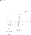
- Fig. 1 and Fig. 2 illustrate a puncture apparatus 1 according to the present embodiment of the present invention.
- the puncture apparatus 1 of the present embodiment includes a needle member 2, a puncture assisting member 3, a detector 4, a processing apparatus 5, and a biasing member 6.
- Fig. 1 illustrates a state before the needle member 2 and the detector 4 of the puncture apparatus 1 are inserted into a living body.
- Fig. 2 illustrates a state in which puncturing of the needle member 2 and the detector 4 of the puncture apparatus 1 into the living body is completed.
- the needle member 2 is a tubular hollow needle that defines a hollow portion.
- the needle member 2 is provided with a deformable flexible portion 10.
- the needle member 2 includes the flexible portion 10, when the needle member 2 punctured from a biological surface BS (see Fig. 2 ) into the living body is removed (hereinafter simply referred to as "at the time of removal of the needle member 2"), even if a bending moment acts on the needle member 2, the flexible portion 10 is deformed, thereby preventing the fracture of the needle member 2.
- a metal material such as stainless steel, aluminum, an aluminum alloy, titanium, or a titanium alloy may be used.
- the puncture assisting member 3 is movable or deformable in an axial direction B of the needle member 2 between a restricting position and a permissive position.
- the restricting position is a position outside the flexible portion 10 of the needle member 2 in a radial direction A of the needle member 2 and restricting deformation of the flexible portion 10
- the permissive position is a position not outside the flexible portion 10 in the radial direction A and permitting deformation of the flexible portion 10.
- Fig. 1 illustrates a state in which the puncture assisting member 3 is at a restricting position
- Fig. 2 illustrates a state in which the puncture assisting member 3 is at a permissive position.
- proximal end direction B1 a direction from a distal side to a proximal side of the needle member 2 in the axial direction B of the needle member 2
- distal end direction B2 a direction from the proximal side to the distal side of the needle member 2 in the axial direction B of the needle member 2.
- the puncture assisting member 3 at the time of puncturing of the needle member 2 means during the operation of puncturing the living body with the needle member 2.
- the puncture assisting member 3 is moved or deformed from the restricting position to the permissive position in conjunction with the operation of insertion of the flexible portion 10 into the living body.
- the puncture assisting member 3 moves or deforms from the restricting position to the permissive position. In this manner, in a state in which the flexible portion 10 is still out of the living body, the puncture assisting member 3 is positioned on an outer periphery of the flexible portion 10.
- the deformation of the flexible portion 10 is restricted by the puncture assisting member 3. That is, even if a puncturing direction of the needle member 2 is deviated from the distal end direction B2 during the operation of puncturing the living body with the needle member 2, the deformation of the flexible portion 10 is restricted by the puncture assisting member 3, so that the puncturing operation can be safely performed.
- the puncture assisting member 3 is moved or deformed from the restricting position to the permissive position. In other words, the puncture assisting member 3 is not inserted into the living body together with the flexible portion 10. In this manner, with the configuration in which the puncture assisting member 3 is not inserted into the living body, pain of a person to be punctured can be reduced when needle member 2 is inserted into the body.
- a resin material for example, may be used as a material for the puncture assisting member 3.
- the resin material include: thermoplastic resins used in injection molding such as ABS resin, AS resin, polyethylene, polypropylene, polystyrene, polyvinyl chloride, polyvinylidene chloride resin, polyphenylene oxide, thermoplastic polyurethane, polymethylene methacrylate, polyoxyethylene, fluorine resin, polycarbonate, polyamide, acetal resin, acrylic resin, and polyethylene terephthalate; and thermosetting resins such as phenol resin, epoxy resin, silicone resin, and unsaturated polyester.
- thermoplastic resins used in injection molding such as ABS resin, AS resin, polyethylene, polypropylene, polystyrene, polyvinyl chloride, polyvinylidene chloride resin, polyphenylene oxide, thermoplastic polyurethane, polymethylene methacrylate, polyoxyethylene, fluorine resin, polycarbonate, polyamide, acetal resin, acrylic resin, and polyethylene ter
- the detector 4 is positioned in the hollow portion of the needle member 2 and can detect a substance to be measured in the living body.
- the detector 4 of the present embodiment is a linear wire member positioned in the hollow portion in the needle member 2.
- the detector 4 of the present embodiment extends along the axial direction B of the needle member 2 in the hollow portion in the needle member 2.
- a member configured to detect an electric signal corresponding to an amount or concentration of the substance to be measured can be used.
- the detector 4 of the present embodiment is a wire electrode having a circular shape in lateral cross section.
- two wire electrodes serving as the detector 4 are accommodated in the hollow portion of the needle member 2.
- the wire electrodes serving as the detector 4 of the present embodiment have an outer diameter of 0.02 mm to 0.2 mm.
- the detector 4" when describing the two wire electrodes of the detector 4 without discrimination, they are correctively referred to as the "detector 4", and when two wire electrodes of the detector 4 need to be discriminated for description, one of the wire electrodes is referred to as a "first detector 4a", and the other is referred to as a "second detector 4b".
- the first detector 4a includes a detection section formed basically of a conductive core and configured to detect the substance to be measured on an outer wall of the core, and a protecting portion made of an insulating material coated on the outer wall of the core.
- the detection section is a working electrode configured to detect a change in electrical characteristics of the substance to be measured and is formed on the surface of the core by means of a thin film forming method such as dipping, electrolytic polymerization, sputtering, and spray coating.
- the second detector 4b constitutes a reference electrode for a working electrode serving as the detection section described above.
- Three pieces of wire electrodes may be disposed in the hollow portion as the detector 4, and the three wire electrodes may constitute the working electrode, the reference electrode, and a counter electrode of the detector 4, respectively.
- the three wire electrodes may constitute the working electrode, the reference electrode, and a counter electrode of the detector 4, respectively.
- a configuration in which the needle member 2 itself is used as the reference electrode or the counter electrode is also applicable.
- a connection section electrically connected to the processing apparatus 5 is provided at a proximal end portion of the detector 4 of the present embodiment. Information on the substance to be measured detected by the detection section is transmitted to the processing apparatus 5 via the connection section.
- the processing apparatus 5 can process the information detected by the detector 4.
- the needle member 2 described above is fixed to the processing apparatus 5.
- the puncture assisting member 3 described above is attached to the processing apparatus 5 so as to be movable or deformable in the axial direction B.
- the puncture assisting member 3 of the present embodiment is attached to the processing apparatus 5 so as to be movable in the axial direction B.
- the processing apparatus 5 of the present embodiment includes an apparatus main body 5a and a base plate 5b for supporting the apparatus main body 5a.
- a lower surface 5b1 which is a surface on one side of the base plate 5b in a thickness direction, opposes the biological surface BS in contact
- the apparatus main body 5a is supported on an upper surface 5b2, which is a surface on the other side in the thickness direction.
- the apparatus main body 5a is detachably attached to the base plate 5b.
- the base plate 5b may support the needle member 2.
- An adhesive portion coated with an adhesive agent or the like is formed on the lower surface 5b1 of the base plate 5b. Puncturing of the needle member 2 of the puncture apparatus 1 of the present embodiment is completed by bringing the lower surface 5b1 of the base plate 5b into contact with the biological surface BS.
- the processing apparatus 5 includes at least the apparatus main body 5a for processing information about the concentration and the amount of the substance to be measured, and for performing communication control.
- the processing apparatus 5 may be configured not to include the base plate 5b (see Fig. 16 , which will be described later).
- the processing apparatus 5 is, for example, a plate shape having a surface of approximately 30 mm x 30 mm and a thickness of about 7 mm to 20 mm.
- the biasing member 6 biases the puncture assisting member 3 at the permissive position in the distal end direction B2 along the axial direction B so as to restore the puncture assisting member 3 to the restricting position.
- the puncture assisting member 3 can be returned to the initial state, that is, to the restricting position when the needle member 2 is removed. Accordingly, the puncture assisting member 3 can be reliably held at the restricting position in a state before the puncture apparatus 1 is used.
- the biasing member 6 may be a coil spring positioned between the processing apparatus 5 and the puncture assisting member 3.
- the processing apparatus 5 is attached to the biological surface BS by a sticking portion formed of, for example, an adhesive or the like, but the biasing force of the biasing member 6 is smaller than the force applied to the biological surface BS of the sticking portion. By doing so, it is possible to prevent the sticking portion from being separated from the biological surface BS by the biasing force of the biasing member 6.
- the puncture apparatus 1 of the present embodiment includes the detector 4 and the processing apparatus 5 in addition to the needle member 2 and the puncture assisting member 3 and constitutes a measuring apparatus capable of measuring the substance to be measured.
- a detector 4 accommodated in the needle member 2 detects the substance to be measured and transmits information on a detection result to the processing apparatus 5.
- the apparatus main body 5a of the processing apparatus 5 includes a processor, a memory, a battery, and the like, analyzes information on a detection result received from the detector 4, and transmits an analysis result to an external apparatus such as a display apparatus as necessary.
- the measuring apparatus as the puncture apparatus 1 of the present embodiment is attached to a person to be punctured by being in a state in which the needle member 2 and the detector 4 are punctured into the living body.
- the puncture assisting member 3 and the processing apparatus 5 are disposed on the biological surface BS of the person to be punctured.
- the measuring apparatus as the puncture apparatus 1 of the present embodiment measures the substance to be measured in a body fluid of the person to be punctured over time while the apparatus is attached to the person to be punctured.
- a time period during which the measuring apparatus as the puncture apparatus 1 of the present embodiment is attached to the person to be punctured is determined as appropriate in the judgment of the doctor or the like, for example, several hours, several days, a week, a month, and the like.
- the substance to be measured is not particularly limited, for example, glucose, oxygen, pH, lactic acid, or the like in an interstitial fluid can be measured according to the selection of the detector 4.
- the needle member 2 and the puncture assisting member 3 of the measuring apparatus as the puncture apparatus 1 of the present embodiment will be described in detail below.
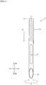
- Fig. 3 is a drawing illustrating only the needle member 2.
- the needle member 2 of the present embodiment is a pipe body having a substantially constant outer diameter and inner diameter regardless of a position in the axial direction B.
- a blade surface 2a inclined with respect to the axial direction B is formed at the distal end portion in the axial direction B of the needle member 2.
- the outer diameter and inner diameter of the needle member 2 may be gradually reduced in the distal end direction B2 along the axial direction B.
- one of the outer diameter and inner diameter of the needle member 2 may be gradually reduced in the distal end direction B2 along the axial direction B, and the other of the outer diameter and inner diameter of the needle member 2 may be substantially constant regardless of the position in the axial direction B.
- a through-hole 2b is formed in a side wall of the needle member 2.
- the through-hole 2b is provided at a position closer to the proximal side than a region where the blade surface 2a is formed in the axial direction B, and is provided at a position closer to the distal side than a region where the flexible portion 10 is formed.
- the needle member 2 of the present embodiment is fixed to the processing apparatus 5 in a state protruding from the processing apparatus 5 on one side in the thickness direction of the processing apparatus 5 having a low-profile shape.
- the flexible portion 10 of the present embodiment is provided at least on the proximal end portion of the needle member 2. More specifically, as illustrated in Fig. 3 , the flexible portion 10 of the present embodiment is provided only at the proximal end portion of the needle member 2.
- the "proximal end of the needle member 2" means a position flush with the biological surface BS of the needle member 2 in a state in which the needle member 2 of the puncture apparatus 1 is inserted into the living body through the biological surface BS to the maximum (see Fig. 2 ).
- the position of the lower surface 5b1 of the base plate 5b corresponds to the position of the proximal end of the needle member 2.
- the flexible portion 10 of the present embodiment is formed preferably over a range of 1 mm or more in the distal end direction B2 along the axial direction B from the proximal end of the needle member 2 so as to be indwelled from the epidermis including at least a large number of nerves over a papillary layer and a papillary lower layer of dermis and, more preferably, formed over a range of 2 mm or more so as to be indwelled over the entire area of the dermis. Accordingly, the flexible portion 10 may be formed over the entire area (for example, 3 mm to 10 mm) from the proximal end to the distal end of the needle member 2.
- the flexible portion 10 be, for example, about one half the total length in the axial direction B of the needle member 2 from the proximal end of the needle member 2 (for example, about 1.5 mm to 5 mm) .
- the flexible portion 10 of the present embodiment is formed in a region including a proximal end portion in a range of 2 mm to 4 mm from the proximal end of the needle member 2 when the needle member 2 is completed to be inserted into the living body.
- the flexible portion 10 of the present embodiment is constituted by a portion (refer to reference numeral "S1" in Fig. 3 ) in which a slit 11 extending in a spiral manner along a spiral direction D in the axial direction B of the needle member 2 is formed. If the flexible portion 10 is formed by using the slit 11 extending in a spiral manner as in the present embodiment, the flexible portion 10 can be deformed in an any radial direction A. With the provision of such a flexible portion 10, the needle member 2 can be deformed in any radial direction A with respect to the processing apparatus 5.
- the flexible portion 10 can be flexibly deformed in accordance with a rotational direction of bending moment applied when the needle member 2 is removed from the inside of the living body. Therefore, it is possible to further reduce the risk of fracture when the needle member 2 is removed from the living body.
- Fig. 4A is illustrates a flexible portion 110 as a modified example of the flexible portion 10 of the present embodiment illustrated in Fig. 3 .
- a flexible portion 110 illustrated in Fig. 4A is formed of a portion (see reference sign "S1" in Fig. 4A ) in which a slit 111 extending in a spiral manner along the spiral direction D is formed in the axial direction B of the needle member 2.
- the slit 111 illustrated in Fig. 4A differs from the slit 11 illustrated in Fig. 3 in shape in side view when viewed from outside in the radial direction A of the needle member 2 (see Fig. 4A ).
- a plurality of protruding slit portions 111a protruding in the axial direction B are formed in the slit 111 illustrated in Fig. 4A .
- positions at centers of the protruding slit portions 111a in the axial direction B and centers of the same in the circumferential direction C are defined as center points cp.
- the spiral direction D illustrated in Fig. 4 means an extending direction of a line formed by connecting the center points cp between the protruding slit portions 111a adjacent to each other in the circumferential direction C.
- the direction turning from the distal side to the proximal side of the needle member 2 is referred to as a first turning direction D1.
- the direction turning from the proximal side to the distal side of the needle member 2 is referred to as a second turning direction D2.
- the protruding slit portions 111a each include, in sequence in the first turning direction D1 along the spiral direction D of the slit 111, a first portion 111a1 extending away from the first turning direction D1 along the spiral direction D of the slit 111 toward the proximal end direction B1 along the axial direction B, a third portion 111a3 extending toward the first turning direction D1 along the spiral direction D of the slit 111, and a second portion 111a2 extending away from the first turning direction D1 along the spiral direction D of the slit 111 in the distal end direction B2 along the axial direction B.
- the third portion 111a3 is a part of the slit 111 and connects the first portion 111a1 and the second portion 111a2 . More specifically, although the slit 111 illustrated in Fig. 4A extends in a spiral manner, the above-described protruding slit portions 111a are formed continuously along the spiral direction D. Therefore, the slit 111 illustrated in Fig. 4A extends in a wavy shape along the spiral direction D. In this manner, by providing the protruding slit portions 111a protruding in the axial direction B in at least a part of the spiral slit 111, it is possible to prevent the flexible portion 110 from being torsionally deformed.
- Fig. 4B is an enlarged view of one of the protruding slit portions 111a of the slit 111 in Fig. 4A .
- first protruding portions 112a and second protruding portions 112b butt against and interfere with each other.
- the first protruding portions 112a are positioned in the distal end direction B2 along the axial direction B with the protruding slit portions 111a of the slit 111 interposed therebetween.
- the first protruding portions 112a constitute a part of the side wall of the needle member 2, and each have a shape that is convex in the proximal end direction B1 along the axial direction B.
- the second protruding portions 112b are positioned in the proximal end direction B1 along the axial direction B with the protruding slit portions 111a of the slit 111 interposed therebetween.
- the second protruding portions 112b constitute a part of the side wall of the needle member 2, and each have a shape that is convex in the distal end direction B2 along the axial direction B.
- the second protruding portions 112b continue and are adjacent in the circumferential direction C of the needle member 2 to second valley bottom edge portions 113b opposing the first protruding portions 112a in the axial direction B.
- first protruding portions 112a protrude in the proximal end direction B1 along the axial direction B
- the second protruding portions 112b protrude in the distal end direction B2 along the axial direction B.
- the first protruding portions 112a and the second protruding portions 112b are adjacent to each other in the circumferential direction C of the needle member 2 with the protruding slit portions 111a of the slit 111 interposed therebetween.
- the first protruding portions 112a and the second protruding portions 112b butt against and interfere with each other in the circumferential direction C, whereby the torsional deformation of the flexible portion 110 can be prevented.
- an angle of the slit 111 in the spiral direction D with respect to the radial direction A of the needle member 2 is preferably in the range of 10° to 45°.
- the plurality of protruding slit portions 111a protruding in the proximal end direction B1 along the axial direction B are alternately arranged in a spiral manner alternately with interlocking slit portions 111b. Accordingly, in other words, the plurality of first protruding portions 112a protruding from the first valley bottom edge portions 113a in the proximal end direction B1 in the axial direction B are intermittently arranged at a predetermined interval in the spiral direction D.
- a plurality of the second protruding portions 112b protruding from the second valley bottom edge portions 113b in the distal end direction B2 along the axial direction B are intermittently arranged at a predetermined interval in the spiral direction D.
- the protruding slit portions 111a and the interlocking slit portions 111b by alternately arranging the protruding slit portions 111a and the interlocking slit portions 111b, the first protruding portions 112a and the second valley bottom edge portions 113b butt against each other in the axial direction B at the time of puncture when the largest external force in the axial direction B is applied to the needle member 2, and the second protruding portions 112b and the first valley bottom edge portions 113a butt against each other in the axial direction B. Accordingly, deformation of the flexible portion 110 in the axial direction B may be minimized. Therefore, the operation at the time of the puncturing operation can be stabilized.
- Fig. 5A, Fig. 5B, and Fig. 5C are drawings illustrating another modified example of the flexible portion 10 of the present embodiment illustrated in Fig. 3 .
- Fig. 5A is a drawing illustrating a flexible portion 210 as a modified example of the flexible portion 10 of the present embodiment illustrated in Fig. 3 .
- Fig. 5B is a drawing illustrating a flexible portion 310 as a modified example of the flexible portion 10 of the present embodiment illustrated in Fig. 3 .
- Fig. 5C is a drawing illustrating a flexible portion 410 as a modified example of the flexible portion 10 of the present embodiment illustrated in Fig. 3 .
- the flexible portion 210 illustrated in Fig. 5A is formed of a portion in which a slit 211 extending in a spiral manner is formed in the axial direction B of the needle member 2.
- the slit 211 illustrated in Fig. 5A differs from the slit 11 illustrated in Fig. 3 in shape in side view when viewed from outside in the radial direction A of the needle member 2 (see Fig. 5A ).
- protruding slit portions 211a protruding in the axial direction B are formed in the slit 211 illustrated in Fig. 5A .
- the protruding slit portions 211a each include, in sequence in the first turning direction D1 along the spiral direction D of the slit 211, a first portion 211a1 extending away from the first turning direction D1 along the spiral direction D of the slit 211 in the proximal end direction B1 along the axial direction B, a third portion 211a3 extending in the first turning direction D1 along the spiral direction D of the slit 211, and a second portion 211a2 extending away from the first turning direction D1 along the spiral direction D of the slit 211 in the distal end direction B2 along the axial direction B.
- the third portion 211a3 is a part of the slit 211 and connects the first portion 211a1 and the second portion 211a2. More specifically, the slit 211 illustrated in Fig. 5A extends in a spiral manner, and the above-described protruding slit portions 211a are formed continuously along the spiral direction D. Therefore, the slit 211 illustrated in Fig. 5A extends in a wavy shape along the spiral direction D. In this manner, by providing the protruding slit portions 211a protruding in the proximal end direction B1 along the axial direction B in at least a part of the spiral slit 211, it is possible to prevent the flexible portion 210 from being torsionally deformed.
- first protruding portions 212a and second protruding portions 212b butt against and interfere with each other.
- the first protruding portions 212a are positioned in the distal end direction B2 along the axial direction B with the protruding slit portions 211a of the slit 211 interposed therebetween.
- the first protruding portions 212a constitute a part of the side wall of the needle member 2, and each have a shape that is convex in the proximal end direction B1 along the axial direction B.
- the second protruding portions 212b are positioned in the proximal end direction B1 along the axial direction B with the protruding slit portions 211a of the slit 211 interposed therebetween.
- the second protruding portions 212b constitute a part of the side wall of the needle member 2, and each have a shape that is convex in the distal end direction B2 along the axial direction B.
- the second protruding portions 212b continue and are adjacent to valley bottom edge portions 213 opposing the first protruding portion 212a in the circumferential direction C in the axial direction B.
- first protruding portions 212a protrude in the proximal end direction B1 along the axial direction B
- the second protruding portions 212b protrude in the distal end direction B2 along the axial direction B.
- the first protruding portions 212a and the second protruding portions 212b are adjacent to each other in the circumferential direction C of the needle member 2 with the protruding slit portions 211a of the slit 211 interposed therebetween.
- the first protruding portions 212a and the second protruding portions 212b butt against and interfere with each other in the circumferential direction C, whereby the torsional deformation of the flexible portion 210 can be prevented.
- protruding slit portions 211b protruding in the circumferential direction C are formed in the slit 211 illustrated in Fig. 5A .
- a protruding slit portion protruding in the axial direction B will be referred to as a "first protruding slit portion”
- a protruding slit portion protruding in a circumferential direction C will be referred to as a "second protruding slit portion”.
- the second protruding slit portions 211b of the slit 211 illustrated in Fig. 5A include, in sequence in the first turning direction D1 along the spiral direction D of the slit 211, first portions 211b1 extending toward one side in the circumferential direction C of the needle member 2, a third portion 211b3 extending from the first turning direction D1 along the spiral direction D of the slit 211 in the proximal end direction B1 along the axial direction B, and a second portion 211b2 extending away from each other toward the other side in the circumferential direction C of the needle member 2.
- the third portions 211b3 constitute a part of the slit 211 and connect the first portion 211b1 and the second portion 211b2.
- the interposing portions 214 are parts of a side wall of the needle member 2, and are positioned at positions interposed between the first portions 211b1 and the second portions 211b2 of the second protruding slit portions 211b in the axial direction B.
- the interposing portions 214 are parts of the second protruding portions 212b and are formed of portions protruding in the circumferential direction C from the distal end of the main body portion of the second protruding portions 212b in the distal end direction B2.
- the first opposing portions 215a are parts of a side wall of the needle member 2 and oppose each other in the axial direction B with the second portion 211b2 interposed therebetween on the proximal side.
- the above-described interposing portions 214 butt against and interfered with the second opposing portions 215b opposed to the distal side across the first portions 211b1 in the axial direction B. Accordingly, the compressive deformation of the flexible portion 210 in the axial direction B may be prevented.
- the first opposing portions 215a and the second opposing portions 215b described above are part of the first protruding portion 212a.
- first protruding slit portion 211a and the second protruding slit portions 211b illustrated in Fig. 5A are formed continuously, these portions may be formed at separate positions apart from each other.
- first protruding slit portion 211a illustrated in Fig. 5A is formed in a rectangular shape by the first portion 211a1, the second portion 211a2, and the third portion 211a3 extending linearly, the shape is not limited thereto, and various shapes are applicable.
- a first projection slit 311a may be formed in a triangular shape so as to form a vertex.
- it may also be configured such that it extends in a curved shape.
- the second protruding slit portions 211b illustrated in Fig. 5A include the first portion 211a1 and the second portion 211a2 extending substantially parallel to each other, it is not limited to this shape and may have various shapes. As in second protruding slit portions 311b illustrated in Fig. 5B , the first portions 311b1 and the second portions 311b2 may not be parallel to each other. Further, like second protruding slit portions 411b illustrated in Fig. 5C , a configuration of extending in a curved shape is also applicable.
- the first protruding slit portion 311a and the second protruding slit portions 311b illustrated in Fig. 5B are formed continuously in the same manner as the first protruding slit portion 211a and the second protruding slit portions 211b illustrated in Fig. 5A , but these parts may be formed at separate positions. The same applies to the first protruding slit portion 411a and the second protruding slit portions 411b illustrated in Fig. 5C .
- FIG. 5D is a drawing illustrating still another modified example of the flexible portion 10 of the present embodiment illustrated in Fig. 3 .
- a flexible portion 510 illustrated in Fig. 5D is formed by a portion where a slit 511 extending in the circumferential direction C of the needle member 2 is formed in the axial direction B of the needle member 2.
- the slits 511 extend substantially in parallel to the circumferential direction C.
- the slits 511 are not formed over the entire area in the circumferential direction C, but are formed only in a part of the circumferential direction C.
- the flexible portion 510 in this configuration can be deformed in the radial direction A in the circumferential direction C at a position where the slits 511 are formed.
- a plurality of the slits 511 illustrated in Fig. 5D are provided, and the plurality of slits 511 are divided into a first slit group 516a arranged at a predetermined interval in the axial direction B at a first predetermined position in the circumferential direction C and a second slit group 516b disposed at a predetermined interval in the axial direction B, at a second predetermined position in the circumferential direction C.
- the first predetermined position and the second predetermined position are opposed to each other in the radial direction A. That is, the first slit group 516a and the second slit group 516b are disposed at positions opposed to each other in the radial direction A.
- the flexible portion 510 illustrated in Fig. 5D is configured to be deformable only in an opposite direction (left-right direction in Fig. 5D ) in which the first slit group 516a and the second slit group 516b oppose each other. In this manner, the flexible portion 510 may be deformable only in a part of the radial direction A. However, because a rotation direction of the bending moment applied to the needle member 2 at the time of removal is not constant, it is preferable to form the flexible portions 10, 110, 210, 310, and 410 that can be deformed in any direction in the radial direction A as illustrated in Fig. 3 , Fig. 4A , Fig. 4B , Fig. 5A, Fig. 5B, and Fig.
- the provision of a slit shape configured to restrict the spread of a slit gap when a force is applied to the needle member 2 in a removal direction can prevent damages caused by the needle member 2 being caught by the biological tissue when the needle member is removed from the living body.
- the slit 511 belonging to the first slit group 516a and the slit 511 belonging to the second slit group 516b are formed at different positions in the axial direction B.
- fluctuation in strength of the flexible portion 510 in accordance with the position in the axial direction B can be reduced, and fluctuation in flexibility due to the position in the axial direction B can be reduced.
- FIG. 6 is a drawing illustrating still another modified example of the flexible portion 10 of the present embodiment illustrated in Fig. 3 .
- a flexible portion 610 illustrated in Fig. 6 is formed of a portion (see reference numeral "S1" in Fig. 6 ) in which a circumferential groove 611 extending in the circumferential direction C is formed in the axial direction B of the needle member 2.
- the rigidity of the portion where the circumferential groove 611 is formed can be made lower than that of the other portion. Therefore, the portion where the circumferential groove 611 is formed can be made to be the flexible portion 610 that is more easily deformed than the other portions.
- the depth of the circumferential groove 611 in the radial direction A is preferably, for example, 40% to 70% of the thickness of the needle member 2, and more preferably 50% to 70%.
- the deformability of the flexible portion 610 can be appropriately adjusted by the depth of the circumferential groove 611, the number of circumferential grooves 611, the pitch of the circumferential groove 611, and the like. In an example illustrated in Fig. 6 , six circumferential grooves 611 are provided.
- the circumferential groove 611 is preferably formed over the entire area in the circumferential direction C.
- the flexible portion illustrated in Fig. 1 to Fig. 6 is preferably configured to be elastically deformable in a range smaller than 90° in a predetermined direction within the radial direction A, and more preferably, to be elastically deformable in a range of 0° to 30°.
- the pitch in the axial direction B of the slit illustrated in Fig. 1 to Fig. 5 and the pitch in the axial direction B of the circumferential groove illustrated in Fig. 6 can be set in a range of 0.1 mm to 1.5 mm, for example, in accordance with the desired deformability of the flexible portion. If the pitch is set to be small, the deformability can be enhanced.
- the thickness of the needle member 2 illustrated in Fig. 1 to Fig. 6 is set in a range of 0.02 mm to 0.15 mm, for example.
- the pitch in the axial direction B of the slit illustrated in Fig. 1 to Fig. 5 and the pitch in the axial direction B of the circumferential groove illustrated in Fig. 6 are preferably set in a range of 0.3 mm to 0.7 mm, and more preferably in a range of 0.4 mm to 0.6 mm.
- the slit illustrated in Fig. 1 to Fig. 5 and the circumferential grooves illustrated in Fig. 6 can be realized by various processing methods such as laser processing, grinding processing, and press processing, and the like.
- the measuring apparatus as the puncture apparatus 1 of the present embodiment is maintained in a state of being attached to the person to be punctured over a period of time that is determined as appropriate in the judgment of the doctor or the like, such as several hours, several days, a week, a month, and the like.
- a portion of the measuring apparatus as the puncture apparatus 1 exposed outside the biological surface BS is susceptible to an external force.
- an external force is applied to the measuring apparatus as the puncture apparatus 1, the needle member 2 is pushed into the skin or subcutaneous tissue or pulled in a direction along the biological surface.
- the person to be punctured feels pain at a site where the needle member 2 is inserted.
- the flexible portion 10 is deformed and buffered, so that damage to the skin or the subcutaneous tissue by the needle member 2 can be reduced. Therefore, the pain felt by the person to be punctured can be reduced.
- the needle member having no flexible portion 10 may fracture at a position near the biological surface BS.
- the flexible portion 10 is elastically deformed to buffer the external force, so that the needle member 2 can be prevented from fracturing.
- the proximal end portion of the needle member 2 is positioned in the vicinity of the biological surface BS in a state in which the measuring apparatus as the puncture apparatus 1 is attached to the living body. Therefore, it is possible to further prevent fracture of the needle member 2 in a state in which the measuring apparatus as the puncture apparatus 1 is attached to the living body.
- the detector 4 is accommodated in the needle member 2. Therefore, in the case of a needle member without the flexible portion 10, when an external force is applied to the puncture apparatus 1 exposed outside the biological surface BS, the position in the living body tends to fluctuate, and the detection accuracy by the detector 4 may deteriorate. On the other hand, in the case of the needle member 2 including the flexible portion 10 of the present embodiment, even when external force is applied to the puncture apparatus 1 exposed outside the biological surface BS, the flexible portion 10 is deformed, so that the position in the living body is hardly fluctuated. As a result, it is possible to prevent a decrease in the detection accuracy by the detector 4.
- the needle member having no flexible portion 10 when a bending moment (external force in the rotational direction) acts on the needle member at the time of removal of the needle member, there is a possibility that new damage to the skin or the subcutaneous tissue is caused in addition to problems of breakage, bending and fracture of the needle member described above.
- the needle member 2 when the needle member 2 is provided with the flexible portion 10, even if an external force in the rotational direction is applied to the needle member 2 at the time of removal of the needle member 2, the flexible portion 10 is deformed, so that new damages to the skin or the subcutaneous tissue can be prevented.
- the puncture assisting member 3 of the present embodiment is cylindrical, and covers the periphery of the flexible portion 10 of the needle member 2 in the radial direction A.
- the thickness of the puncture assisting member 3 is 1 mm to 10 mm, preferably 1 mm to 5 mm, and more preferably 2 mm to 3 mm.
- the puncture assisting member 3 is provided with an attachment section 3a to be attached to the biological surface BS when puncturing the living body with the needle member 2 of the puncture apparatus 1 from the biological surface BS.
- the attachment section 3a of the present embodiment is formed by the distal end of the puncture assisting member 3 in the axial direction B, and butt with the biological surface BS at the time of puncturing.
- the puncture assisting member 3 moves from a position (restricting position) covering the periphery of the flexible portion 10 in the radial direction A to a position (permissive position) not covering the periphery of the flexible portion 10 in the radial direction A.
- the puncture assisting member 3 moves from the restricting position to the permissive position in conjunction with the puncturing operation for moving the needle member 2 in the distal end direction B2 along the axial direction B.
- the puncture assisting member 3 moves in the proximal end direction B1 along the axial direction B1 at the same time as the insertion of the flexible portion 10 into the living body. Therefore, the flexible portion 10 can be inserted into the living body without inserting the puncture assisting member 3 into the living body. Accordingly, because the needle member 2 can be punctured without puncturing the puncture assisting member 3 thicker than the needle member 2 into the living body, the pain felt by the person to be punctured can be reduced as compared with the configuration in which the puncture assisting member is punctured together.
- a difference (clearance) between an inner diameter of the puncture assisting member 3 and an outer diameter of the flexible portion 10 of the needle member 2 is preferably 0.1 mm or less, and more preferably 0.01 mm to 0.05 mm.
- the puncture assisting member 3 when the puncture assisting member 3 is moved in the proximal end direction B1 along the axial direction B with respect to the needle member 2 at the time of puncturing of the needle member 2, the puncture assisting member 3 is accommodated in the processing apparatus 5. Specifically, the puncture assisting member 3 is accommodated in the accommodation unit of the apparatus main body 5a through the opening of the base plate 5b at the time of puncturing of the needle member 2.
- the puncture assisting member 3 of the present embodiment is configured to move with respect to the needle member 2 without being deformed by itself.
- a puncture assisting member configured to achieve the restricting position and the permissive position by deformation is also applicable.
- it may also be a puncture assisting member that is formed by a bellows cylindrical member deformable in the axial direction B.
- Fig. 7 is a drawing illustrating only a puncture assisting member 103 as a modified example of the puncture assisting member 3 illustrated in Fig. 1 .
- the puncture assisting member 103 illustrated in Fig. 7 is different in shape from the puncture assisting member 3 described above.
- the puncture assisting member 103 illustrated in Fig. 7 is provided with an attachment section 103a to be attached to the biological surface BS (see Fig. 2 ) at the time of puncturing of the needle member 2.
- the attachment section 103a illustrated in Fig. 7 is positioned at the distal end of the puncture assisting member 103.
- the attachment section 103a may be provided in the distal end direction B2 along the axial direction B rather than a needle tip.
- the puncture assisting member 103 is configured such that a maximum width W1 in the radial direction A of the attachment section 103a is larger than a maximum width in the radial direction A at a position other than the attachment section 103a of the puncture assisting member 103. More specifically, the puncture assisting member 103 illustrated in Fig.
- the puncture assisting member 103 is cylindrical, and an outer diameter of the puncture assisting member 103 gradually increases as it goes toward the attachment section 103a in the distal end direction B2 along the axial direction B.
- the maximum width W1 of the attachment section 103a of the puncture assisting member 103 corresponds to the outer diameter of the attachment section 103a.
- the thickness of the puncture assisting member 103 illustrated in Fig. 7 is gradually increased in the distal end direction B2 along the axial direction B so that the inner diameter becomes constant regardless of the position in the axial direction B.
- Fig. 8A, Fig. 8B, Fig. 8C , Fig. 8D, and Fig. 8E are drawings illustrating a puncture assisting member 203 as another modified example of the puncture assisting member 3 illustrated in Fig. 1 .
- Fig. 8A to Fig. 8E illustrates a process of deformation of the puncture assisting member 203 at the time of puncturing of the needle member 2.
- the puncture assisting member 203 is sequentially deformed from the state illustrated in Fig. 8A to a state illustrated in Fig. 8E at the time of puncturing of the needle member 2.
- the puncture assisting member 203 illustrated in Fig. 8A to Fig. 8E is cylindrical similar to the puncture assisting member 3 illustrated in Fig. 1 .
- a cylindrical member as the puncture assisting member 203 includes a plurality of cylindrical portions 217 formed by concentrically overlapping in the radial direction A, and has a telescopic mechanism capable of changing the length in the axial direction B by the plurality of cylindrical portions 217 moving in the axial direction B (see Fig. 8A to Fig. 8E ).
- the outer diameter of the cylindrical portion 217 including the attachment section 203a positioned at the distal end of the cylindrical body out of the outer diameters of the plurality of cylindrical portions 217 has a maximum outer diameter in the cylindrical member.
- the outer diameter of the cylindrical portion 217 including the attachment section 203a positioned at the distal end of the cylindrical member corresponds to the maximum width W 1 of the attachment section 203a.
- the puncture assisting member 203 illustrated in Fig. 8 includes four cylindrical portions 217 that are concentrically overlapped with each other in the radial direction A.
- Each of the four cylindrical portions 217 is formed to have a uniform wall thickness. Also, the lengths of the four cylindrical portions 217 in the axial direction B are equal.
- the four cylindrical portions 217 include a first cylindrical portion 217a configured to cover the periphery of the proximal end portion of the needle member 2 and having a smallest outer diameter, a second cylindrical portion 217b positioned outside the first cylindrical portion 217a in the radial direction A, a third cylindrical portion 217c positioned outside the second cylindrical portion 217b in the radial direction A, and a fourth cylindrical portion 217d positioned outside the third cylindrical portion 217c in the radial direction A and having the largest outer diameter.
- the attachment section 203a is formed by the distal end of the fourth cylindrical portion 217d in the axial direction B.
- Each of the cylindrical portions 217 includes a cylindrical body portion 218, an inner engagement portion 219, and an outer engagement portion 220.
- Fig. 9 is a drawing illustrating the inner engagement portion 219 and the outer engagement portion 220.
- the inner engagement portion 219 is provided to protrude toward an inner side from the cylindrical body portion 218 in the radial direction A, and is engageable with the outer engagement portion 220 of another cylindrical portion 217 adjacent thereto on the inner side in the radial direction A. Further, as illustrated in Fig.
- the outer engagement portion 220 is provided to protrude toward an outer side from the cylindrical body portion 218 in the radial direction A, and is engageable with the inner engagement portion 219 of another cylindrical portion 217 adjacent thereto on the outer side in the radial direction A.
- the inner engagement portion 219 includes an inner proximal portion 230 protruding inward in the radial direction A from the cylindrical body portion 218 and an inner distal end portion 231 extending in the distal end direction B2 along the axial direction B from an inner end of the inner proximal portion 230 in the radial direction A, and an inner concave portion 232 is formed between the cylindrical body portion 218 and the inner distal end portion 231.
- the outer engagement portion 220 includes an outer proximal portion 233 protruding outward from the cylindrical body portion 218 in the radial direction A, and an outer distal end portion 234 extending from the outer end portion of the outer proximal portion 233 in the radial direction A in the proximal end direction B1 along the axial direction B, and an outer concave portion 235 is formed between the cylindrical body portion 218 and the outer distal end portion 234.
- an outer engagement portion 220c of the third cylindrical portion 217c positioned inside in the radial direction A and the inner engagement portion 219d of the fourth cylindrical portion 217d positioned outside in the radial direction A are disposed at positions overlapping each other in the axial direction B.
- the third cylindrical portion 217c and the fourth cylindrical portion 217d can change the total length in the axial direction B until the outer engagement portion 220c of the third cylindrical portion 217c and the inner engagement portion 219d of the fourth cylindrical portion 217d are engaged with each other (see Fig. 8 a) , from a state in which these parts overlap completely with each other in the radial direction A (see Fig. 8B to Fig. 8E ) . Then, in a state in which the outer engagement portion 220c of the third cylindrical portion 217c engages with the inner engagement portion 219d of the fourth cylindrical portion 217d (see Fig.
- the inner distal end portion 231d of the inner engagement portion 219d fits into the outer concave portion 235c of the outer engagement portion 220c.
- the fitting state is not released unless otherwise a force greater than or equal to a predetermined value is applied to the fourth cylindrical portion 217d in the proximal end direction B1 along the axial direction B.
- the engagement relationship between the third cylindrical portion 217c and the fourth cylindrical portion 217d described above is established in any two cylindrical portions 217 that are adjacent to each other in the radial direction A. Therefore, in the puncture assisting member 203 illustrated in Fig. 8A to Fig. 8E , the total length in the axial direction B can be changed to a state in which the inner engagement portion 219 and the outer engagement portion 220 of the adjacent cylindrical portions 217 are engaged (see Fig. 8A ) from a state in which the four cylindrical portions 217 are completely overlapped with each other in the radial direction A (see Fig. 8D and Fig. 8E ).
- the flexible portion 10 illustrated in Fig. 8A to Fig. 8E is formed only at the proximal end portion of the needle member 2, and in the state illustrated in Fig. 8A and Fig. 8D , deformation in the radial direction A of the flexible portion 10 is restricted by the first cylindrical portion 217a.
- Fig. 8A to Fig. 8D illustrate a state in which the puncture assisting member 203 is at the restricting position.
- a state illustrated in Fig. 8E in which the first cylindrical portion 217a does not cover the periphery of the flexible portion 10 is achieved.
- Fig. 8E illustrates a state in which the puncture assisting member 203 is at the permissive position.
- Fig. 10A, Fig. 10B, and Fig. 10C are drawings illustrating only a puncture assisting member as another modified example of the puncture assisting member 3 as illustrated in Fig. 1 .
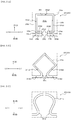
- the puncture assisting member 303 illustrated in Fig. 10A is cylindrical. More specifically, the puncture assisting member 303 illustrated in Fig. 10A is provided with a cylindrical body portion 321 and a flange portion 322 protruding outward in the radial direction A from the cylindrical body portion 321 at a position of the distal end in the axial direction B of the cylindrical body portion 321.
- the attachment section 303a to be attached to the biological surface BS (see Fig. 2 ) at the time of puncturing of the needle member 2 is formed of the flange portion 322.
- the outer shape of the flange portion 322 is not limited to the quadrangular shape illustrated in Fig. 10A and may be any shape. For example, a polygonal shape other than a quadrangular shape as illustrated in Fig. 10B may be used, and a circular shape or an elliptical shape as illustrated in Fig. 10C may also be used.
- Fig. 11 is a drawing illustrating a puncture assisting member 403 as another modified example of the puncture assisting member 3 illustrated in Fig. 1 .
- the puncture assisting member 403 illustrated in Fig. 11 covers not only the flexible portion 10, but also the distal end of the needle member 2 over the outer periphery thereof in the radial direction A when at the restricting position. More specifically, the puncture assisting member 403 in Fig. 11 covers not only the flexible portion 10, but also the entire needle member 2 over the outer periphery thereof in the radial direction A when at the restricting position.
- the puncture assisting member 403 at the restricting position covers the periphery outside the distal end of the needle member 2 in the radial direction A, it is possible to prevent a person performing puncture from touching the needle tip that is the distal end of the needle member 2 before puncturing.
- FIG. 12A, Fig. 12B, and Fig. 12C are drawings illustrating a puncture assisting member as another modified example of the puncture assisting member 3 as illustrated in Fig. 1 .
- a puncture assisting member 503 illustrated in Fig. 12A is a cylindrical member.
- a slit 523 extending to the proximal end of the cylindrical body in the axial direction B is formed on the side wall of the cylindrical member as the puncture assisting member 503.
- the position, size and shape of the slit 523 can be appropriately designed in accordance with the position, size, shape and the like of the electric wiring and the housing of the processing apparatus 5 (see Fig. 1 and the like) . Further, even when the slit 523 is used with an apparatus other than the processing apparatus 5, and even when the apparatus main body 5a is detachable, it is advantageous because it can be used to avoid interference with electric wiring, housing or the like extending from the detector 4.
- a puncture assisting member 603 illustrated in Fig. 12B is formed by turning in a spiral manner and has a cylindrical shape as a whole.
- the puncture of the needle member 2 is performed while twisting the puncture assisting member 603, the flexible portion 10 of the needle member 2 can be compressed toward the inner side in the radial direction A by the puncture assisting member 603. In other words, deformation at the position of the flexible portion 10 can be further prevented. Therefore, at the time of puncturing of the needle member 2, it is possible to further reduce the possibility of breakage, bending, or the like of the flexible portion 10.
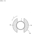
- a puncture assisting member 703 illustrated in Fig. 12C is composed of a plurality of (two in Fig. 12C ) plate portions 724 disposed at different positions in the circumferential direction C.
- the plurality of plate portions 724 are disposed at positions outside the needle member 2 in the radial direction A, and are disposed at equal intervals in the circumferential direction C.
- Fig. 13 is a drawing of the needle member 2 and the puncture assisting member 703 illustrated in Fig. 12C as viewed in the axial direction B. As illustrated in Fig.
- the puncture assisting member 703 is formed by two plate portions 724 that are curved along the circumferential direction C, the number of plate portions and the shape thereof are not particularly limited as long as the puncture assisting member 703 at the restricting position can restrict deformation of the flexible portion 10 in the radial direction A.
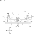
- Fig. 14 and Fig. 15 are drawings illustrating a puncture assisting member 803 as another modified example of the puncture assisting member 3 illustrated in Fig. 1 .
- the puncture assisting member 803 illustrated in Fig. 14 and Fig. 15 differs from the puncture assisting member 3 illustrated in Fig. 1 in that a latched section 826 to be latched by a first latch section 825 provided in the processing apparatus 5 when accommodated in the processing apparatus 5 is provided.
- the processing apparatus 5 includes the first latch section 825 configured to latch the puncture assisting member 803 at the permissive position.
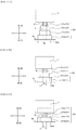
- Fig. 14 illustrates a state in which the needle member 2 is in the course of puncturing and the puncture assisting member 803 is at the restricting position.
- Fig. 15 illustrates a state in which puncture of the needle member 2 is completed and the puncture assisting member 803 is at the permissive position.
- the puncture assisting member 803 includes a cylindrical body portion 827 and a latched section 826 protruding to the outer side in the radial direction A from the cylindrical body portion 827.
- the latched section 826 may be a projection provided only in a part of the circumferential direction C or may be an annular rib provided over the entire circumferential direction C, for example.
- the puncture assisting member 803 moves into the accommodation unit of the processing apparatus 5 at the time of puncturing of the needle member 2.
- the latched section 826 slides over the first latch section 825 formed on an inner wall of the accommodation unit of the processing apparatus 5.
- the first latch section 825 may be formed of, for example, a protrusion formed on the inner wall of the accommodation unit of the processing apparatus 5.
- the processing apparatus 5 illustrated in Fig. 14 and Fig. 15 includes a second latch section 836 configured to latch the puncture assisting member 803 at the restricting position.
- the second latch section 836 illustrated in Fig. 14 and Fig. 15 is formed by an annular rib formed on the inner wall of the accommodation unit of the processing apparatus 5.
- the latched section 826 and the second latch section 836 of the puncture assisting member 803 are formed at positions overlapping each other in the axial direction B. Therefore, when both the processing apparatus 5 and the puncture assisting member 803 are moved apart from each other in the axial direction B, the latched section 826 of the puncture assisting member 803 and the second latch section 836 of the processing apparatus 5 are engaged with each other.
- the puncture assisting member 803 at the permissive position is not separated from the processing apparatus 5. Therefore, the puncture assisting member 803 can be prevented from being unintentionally separated from the processing apparatus 5.
- Fig. 16 is a drawing illustrating a puncture assisting member 903 as another modified example of the puncture assisting member 3 illustrated in Fig. 1 .
- the puncture assisting member 903 illustrated in Fig. 16 illustrates an example in which the flange portion 322 of the puncture assisting member 303 illustrated in Fig. 10A to Fig. 10C is integrally formed with the base plate.
- the puncture assisting member 903 illustrated in Fig. 16 is provided with the cylindrical body portion 921 and a base plate serving as a flange portion 922 protruding outward from the cylindrical body portion 921 in the radial direction A at a position of the distal end of the cylindrical body portion 921 in the axial direction B.
- the attachment section 903a to be attached to the biological surface BS (see Fig. 2 ) at the time of puncturing of the needle member 2 is formed by the base plate serving as the flange portion 922.
- the base plate is not part of the processing apparatus 5, but rather constitutes a part of the puncture assisting member 903. Then, the base plate as the flange portion 322 illustrated in Fig. 16 moves in the proximal end direction B1 along the axial direction B with respect to the needle member 2 at the time of puncturing of the needle member 2.
- the puncture assisting member 903 illustrated in Fig. 16 includes, in addition to the cylindrical body portion 921 and the flange portion 922 described above, a latched section 928 that protrudes from the flange portion 922 toward the processing apparatus 5 at a position outside the cylindrical body portion 921 in the radial direction A.
- the latched section 928 is accommodated in the processing apparatus 5 when the puncture assisting member 903 is set to the permissive position from a restricting position (see Fig. 16 ).
- the latched section 928 is latched by the first latch section 929 provided on the processing apparatus 5 when being accommodated in the processing apparatus 5.
- the processing apparatus 5 includes a first latch section 929 configured to latch the puncture assisting member 903 at the permissive position.
- the latched section 928 illustrated in Fig. 16 includes a main body portion 928a protruding from the flange portion 922 and a claw portion 928b provided on the inner side in the radial direction A of the main body portion 928a.
- the first latch section 929 illustrated in Fig. 16 may be formed by a projection formed on the inner wall of the accommodation unit of the processing apparatus 5 for accommodating the latched section 928.
- the processing apparatus 5 illustrated in Fig. 16 includes a second latch section 937 configured to latch the puncture assisting member 903 at the restricting position.
- the second latch section 937 illustrated in Fig. 16 is formed by an annular rib formed on the inner wall of the accommodation unit of the processing apparatus 5.
- the latched section 928 and the second latch section 937 of the puncture assisting member 903 are formed at positions overlapping each other in the axial direction B. Therefore, when both the processing apparatus 5 and the puncture assisting member 903 are moved apart from each other in the axial direction B, the latched section 928 of the puncture assisting member 903 and the second latch section 937 of the processing apparatus 5 are engaged with each other.
- the puncture assisting member 903 at the permissive position is not separated from the processing apparatus 5. Therefore, the puncture assisting member 903 can be prevented from being unintentionally separated from the processing apparatus 5.
- a plurality of latched sections 928 may be arranged at an interval in the circumferential direction C. Further, as illustrated in Fig. 17B , an annular structure extending over the entire circumferential direction C may also be used.
- Fig. 17A and Fig. 17B are views of the puncture assisting member 903 as viewed from the processing apparatus 5 side (the upper side in Fig. 16 ).
- the puncture apparatus is not limited to the specific configuration described above, and various modified examples and changes can be made without departing from the scope of the appended claims .
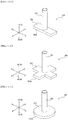
- the needle member is not limited thereto, and may be a needle member 1002 that protrudes from a position other than the central position of the processing apparatus 5 as illustrated in Fig. 18 .
- the puncture apparatus illustrated in Fig. 1 to Fig. 17 although the needle member is protruded from a central position of the processing apparatus, the needle member is not limited thereto, and may be a needle member 1002 that protrudes from a position other than the central position of the processing apparatus 5 as illustrated in Fig. 18 .
- the needle member protrudes in the thickness direction of the plate-shaped processing apparatus, but is not limited to this configuration, a needle member 1102 may be inclined and protruded with respect to the thickness direction of the plate-shaped processing apparatus 5, as illustrated in Fig. 19 .
- the processing apparatus 5 of the biological surface BS (see Fig. 2 ) can easily be moved on the biological surface BS along the axial direction B of the needle member 1102 being punctured.
- the processing apparatus 5 can easily be moved in the left-right direction by an external force.
- the flexible portion provided on the needle member 1102 is configured to be easily deformable in the direction along the axial direction B on the biological surface BS (in the lateral direction in Fig. 19 ).
- the distal end surface in the axial direction B constituting an attachment section 1103a of a puncture assisting member 1103 is formed at an angle substantially parallel to a lower surface 5b1 of a base plate 5b of the processing apparatus 5 so as to easily be attached with the biological surface BS at the time of the puncturing operation of the needle member 1102.
- the measuring apparatus as the puncture apparatus is described, but another puncture apparatus that does not include the detector may also be used as another puncture apparatus.
- a measuring apparatus including a detecting member is used as the puncture apparatus, it is possible to prevent deterioration in detection accuracy by the detector by providing a flexible portion as described above.
- the present disclosure relates to a puncture apparatus.
Landscapes
- Health & Medical Sciences (AREA)
- Life Sciences & Earth Sciences (AREA)
- Veterinary Medicine (AREA)
- Engineering & Computer Science (AREA)
- Biomedical Technology (AREA)
- Heart & Thoracic Surgery (AREA)
- Animal Behavior & Ethology (AREA)
- General Health & Medical Sciences (AREA)
- Public Health (AREA)
- Physics & Mathematics (AREA)
- Surgery (AREA)
- Molecular Biology (AREA)
- Medical Informatics (AREA)
- Pathology (AREA)
- Biophysics (AREA)
- Optics & Photonics (AREA)
- Hematology (AREA)
- Anesthesiology (AREA)
- Vascular Medicine (AREA)
- Emergency Medicine (AREA)
- Nuclear Medicine, Radiotherapy & Molecular Imaging (AREA)
- Pulmonology (AREA)
- Infusion, Injection, And Reservoir Apparatuses (AREA)
- Media Introduction/Drainage Providing Device (AREA)
Abstract
Description
- The present disclosure relates to a puncture apparatus.
- A needle member that is punctured through a biological surface into a living body for various purposes, such as injection of a drug solution and collection of blood, is known in the related art. For example,
Patent Literature 1 discloses a catheter as a needle member, the catheter including a rigid main body portion and a flexible body portion. - PTL 1:
JP-A-2015-164545 - When removing a punctured needle member, a bending moment may act on the needle member. When the bending moment acts on the needle member, there is a risk of fracture of the needle member. Therefore, with the flexible body portion as in the catheter disclosed in
Patent Literature 1, the chance that the catheter (needle member) will fracture can be inhibited. - However, in
Patent Literature 1, a sleeve positioned outside the catheter as the needle member is provided in order to allow insertion of the flexible body portion into the living body. Therefore, because the catheter as the needle member and the sleeve thicker than the catheter are punctured, a person to be punctured, such as a patient to get punctured, feels much more pain as compared with a case in which the patient gets punctured with only a catheter as a needle member. - Accordingly, it is an object of the present disclosure to provide a puncture apparatus having a configuration capable of reducing the chance of breakage, bending, and fracture of a needle member at the time of puncturing and removal, while alleviating the pain of a person to be punctured at the time of puncturing.
- A puncture apparatus according to a first aspect of the present invention includes: a needle member having a tubular shape, the needle member including a flexible portion that is deformable; and a puncture assisting member being movable or deformable in an axial direction of the needle member between a restricting position and a permissive position, the restricting position being a position outside the flexible portion of the needle member in a radial direction of the needle member and restricting deformation of the flexible portion, the permissive position being a position not outside the flexible portion in the radial direction and permitting deformation of the flexible portion, the puncture assisting member moves or deforms from the restricting position to the permissive position in conjunction with an operation of inserting the flexible portion into the living body at the time of puncturing the living body with the needle member.
- According to an embodiment of the present invention, the puncture assisting member includes an attachment section positioned at a distal end in the axial direction and configured to be attached to the biological surface when the needle member punctures the living body, and a maximum width in the radial direction of the attachment section is larger than a maximum width of the puncture assisting member in the radial direction at a position other than the attachment section.
- According to an embodiment of the present invention, the puncture assisting member is cylindrical, and an outer diameter of the puncture assisting member gradually increases from a proximal side toward the attachment section at the distal end in the axial direction.
- According to an embodiment of the present invention, the cylindrical member includes a plurality of cylindrical portions concentrically overlapping one another in the radial direction, the plurality of cylindrical portions has a telescopic mechanism capable of varying a length in the axial direction by moving in the axial direction, and of outer diameters of the plurality of cylindrical portions, an outer diameter of a cylindrical portion including the attachment section is largest.
- According to an embodiment of the present invention, the puncture assisting member is cylindrical, and includes a cylindrical body portion and a flange portion protruding outward in the radial direction from the cylindrical body portion at a position of the distal end of the cylindrical body portion in the axial direction, and the attachment section is formed of the flange portion.
- According to an embodiment of the present invention, the puncture assisting member is cylindrical and includes a slit extending to a proximal end formed in the axial direction.
- The puncture apparatus according to an embodiment of the present invention includes: a detector positioned in a hollow portion of the needle member and capable of detecting a substance to be measured in a living body.
- The puncture apparatus according to an embodiment of the present invention includes: a processing apparatus configured to process information detected by the detector, and the needle member is fixed to the processing apparatus, and the puncture assisting member is attached to the processing apparatus movably or deformably in the axial direction.
- According to an embodiment of the present invention, the processing apparatus includes a latch section configured to latch the puncture assisting member at the restricting position.
- According to an embodiment of the present invention, the processing apparatus has a flat shape, and the needle member is fixed to one side of the processing apparatus in a thickness direction in a protruding state.
- The puncture apparatus according to an embodiment of the present invention includes : a biasing member configured to bias the puncture assisting member at the permissive position in the axial direction to be restored to the restricting position.
- According to an embodiment of the present invention, the flexible portion is constituted by a portion of the needle member in the axial direction where a slit extending in a spiral manner is formed.
- According to an embodiment of the present invention, the slit includes a protruding slit portion protruding in the axial direction.
- According to an embodiment of the present invention, if the protruding slit portion is defined as a first protruding slit portion, the slit includes a second protruding slit portion protruding in a circumferential direction of the needle member.
- According to an embodiment of the present invention, the flexible portion is constituted by a portion of the needle member in the axial direction where a slit extending in a circumferential direction of the needle member is formed.
- According to an embodiment of the present invention, the flexible portion is constituted by a portion of the needle member in the axial direction where a circumferential groove extending in a circumferential direction of the needle member is formed.
- The present disclosure provides a puncture apparatus having a configuration capable of reducing the chance of breakage, bending, and fracture of a needle member at the time of puncturing and removal, while alleviating the pain of a person to be punctured at the time of puncturing.
-
- [
Fig. 1] Fig. 1 is a drawing illustrating a state in which a puncture assisting member is at a restricting position in a puncture apparatus according to an embodiment. - [
Fig. 2] Fig. 2 is a drawing illustrating a state in which the puncture assisting member is at a permissive position in the puncture apparatus illustrated inFig. 1 . - [
Fig. 3] Fig. 3 is a drawing illustrating only a needle member illustrated inFig. 1 . - [
Fig. 4A] Fig. 4A is a drawing illustrating a flexible portion as a modified example of the flexible portion illustrated inFig. 3 . - [
Fig. 4B] Fig. 4B is an enlarged view of a protruding slit portion of a slit inFig. 4A . - [
Fig. 5A] Fig. 5A is a drawing illustrating another modified example of the flexible portion illustrated inFig. 3 . - [
Fig. 5B] Fig. 5B is a drawing illustrating another modified example of the flexible portion illustrated inFig. 3 . - [
Fig. 5C] Fig. 5C is a drawing illustrating another modified example of the flexible portion illustrated inFig. 3 . - [
Fig. 5D] Fig. 5D is a drawing illustrating another modified example of the flexible portion illustrated inFig. 3 . - [
Fig. 6] Fig. 6 is a drawing illustrating another modified example of the flexible portion illustrated inFig. 3 . - [
Fig. 7] Fig. 7 is a drawing illustrating only a puncture assisting member as a modified example of the puncture assisting member illustrated inFig. 1 . - [
Fig. 8A] Fig. 8A is a drawing illustrating a puncture assisting member as a modified example of the puncture assisting member illustrated inFig. 1 , illustrating a part of a process of deformation of the puncture assisting member when the needle member punctures a living body. - [
Fig. 8B] Fig. 8B is a drawing illustrating a part of the process of deformation of the puncture assisting member when the needle member punctures the living body, which is different from that ofFig. 8A . - [
Fig. 8C] Fig. 8C is a drawing illustrating a part of the process of deformation of the puncture assisting member when puncturing the needle member, which is different fromFig. 8A and Fig. 8B . - [
Fig. 8D] Fig. 8D is a drawing illustrating a part of the process of deformation of the puncture assisting member when the needle member punctures the living body, which is different fromFig. 8A to Fig. 8C . - [
Fig. 8E] Fig. 8E is a drawing illustrating a part of the process of deformation of the puncture assisting member when the needle member punctures the living body, which is different fromFig. 8A to Fig. 8D . - [
Fig. 9] Fig. 9 is a drawing illustrating an inner engagement portion and an outer engagement portion. - [
Fig. 10A] Fig. 10A is a drawing illustrating only a puncture assisting member as a modified example of the puncture assisting member illustrated inFig. 1 . - [
Fig. 10B] Fig. 10B is a drawing illustrating only a puncture assisting member as a modified example of the puncture assisting member illustrated inFig. 1 . - [
Fig. 10C] Fig. 10C is a drawing illustrating only a puncture assisting member as a modified example of the puncture assisting member illustrated inFig. 1 . - [
Fig. 11] Fig. 11 is a drawing illustrating a puncture assisting member as a modified example of the puncture assisting member illustrated inFig. 1 . - [
Fig. 12A] Fig. 12A is a drawing illustrating a puncture assisting member as a modified example of the puncture assisting member illustrated inFig. 1 . - [
Fig. 12B] Fig. 12B is a drawing illustrating a puncture assisting member as a modified example of the puncture assisting member illustrated inFig. 1 . - [
Fig. 12C] Fig. 12C is a drawing illustrating a puncture assisting member as a modified example of the puncture assisting member illustrated inFig. 1 . - [
Fig. 13] Fig. 13 is a drawing of the needle member and the puncture assisting member illustrated inFig. 12C as viewed in an axial direction. - [
Fig. 14] Fig. 14 is a drawing illustrating a puncture assisting member as a modified example of the puncture assisting member illustrated inFig. 1 and illustrates a state in which the puncture assisting member is at a restricting position. - [
Fig. 15] Fig. 15 is a drawing illustrating a state in which the puncture assisting member illustrated inFig. 14 is at a permissive position. - [
Fig. 16] Fig. 16 is a drawing illustrating a puncture assisting member as a modified example of the puncture assisting member illustrated inFig. 1 . - [
Fig. 17A] Fig. 17A is a drawing illustrating an example of a latched section illustrated inFig. 16 . - [
Fig. 17B] Fig. 17B is a drawing illustrating an example of the latched section illustrated inFig. 16 . - [
Fig. 18] Fig. 18 is a drawing illustrating a needle member and a detector disposed at positions different from those inFig. 1 to Fig. 17 . - [
Fig. 19] Fig. 19 is a drawing illustrating the needle member and the detector disposed at angles different from those inFig. 1 to Fig. 17 . - Referring now to
Fig. 1 to Fig. 19 , an embodiment of a puncture apparatus will be described. The same reference numerals are given to parts and portions common to those in the respective drawings. -
Fig. 1 and Fig. 2 illustrate apuncture apparatus 1 according to the present embodiment of the present invention. As illustrated inFig. 1 and Fig. 2 , thepuncture apparatus 1 of the present embodiment includes aneedle member 2, apuncture assisting member 3, adetector 4, aprocessing apparatus 5, and a biasingmember 6.Fig. 1 illustrates a state before theneedle member 2 and thedetector 4 of thepuncture apparatus 1 are inserted into a living body.Fig. 2 illustrates a state in which puncturing of theneedle member 2 and thedetector 4 of thepuncture apparatus 1 into the living body is completed. - The
needle member 2 is a tubular hollow needle that defines a hollow portion. Theneedle member 2 is provided with a deformableflexible portion 10. - Because the
needle member 2 includes theflexible portion 10, when theneedle member 2 punctured from a biological surface BS (seeFig. 2 ) into the living body is removed (hereinafter simply referred to as "at the time of removal of theneedle member 2"), even if a bending moment acts on theneedle member 2, theflexible portion 10 is deformed, thereby preventing the fracture of theneedle member 2. - As the material of the
needle member 2, for example, a metal material such as stainless steel, aluminum, an aluminum alloy, titanium, or a titanium alloy may be used. - The
puncture assisting member 3 is movable or deformable in an axial direction B of theneedle member 2 between a restricting position and a permissive position. The restricting position is a position outside theflexible portion 10 of theneedle member 2 in a radial direction A of theneedle member 2 and restricting deformation of theflexible portion 10, and the permissive position is a position not outside theflexible portion 10 in the radial direction A and permitting deformation of theflexible portion 10. Further, when puncturing the living body with theneedle member 2 from the biological surface BS (seeFig. 2 ) (hereinafter referred to simply as "at the time of puncturing of theneedle member 2"), thepuncture assisting member 3 moves or deforms from the restricting position to the permissive position in conjunction with the operation of insertion of theflexible portion 10 into the living body.Fig. 1 illustrates a state in which thepuncture assisting member 3 is at a restricting position, andFig. 2 illustrates a state in which thepuncture assisting member 3 is at a permissive position. Hereinafter, a direction from a distal side to a proximal side of theneedle member 2 in the axial direction B of theneedle member 2 is referred to as a "proximal end direction B1". In addition, a direction from the proximal side to the distal side of theneedle member 2 in the axial direction B of theneedle member 2 is referred to as a "distal end direction B2". - The operation and function of the
puncture assisting member 3 at the time of puncturing of theneedle member 2 will now be described in detail. The term "at the time of puncturing of theneedle member 2" means during the operation of puncturing the living body with theneedle member 2. Thepuncture assisting member 3 is moved or deformed from the restricting position to the permissive position in conjunction with the operation of insertion of theflexible portion 10 into the living body. In other words, as theflexible portion 10 inserts into the living body, thepuncture assisting member 3 moves or deforms from the restricting position to the permissive position. In this manner, in a state in which theflexible portion 10 is still out of the living body, thepuncture assisting member 3 is positioned on an outer periphery of theflexible portion 10. In other words, it corresponds to a state in which thepuncture assisting member 3 is at the restricting position. Therefore, the deformation of theflexible portion 10 is restricted by thepuncture assisting member 3. That is, even if a puncturing direction of theneedle member 2 is deviated from the distal end direction B2 during the operation of puncturing the living body with theneedle member 2, the deformation of theflexible portion 10 is restricted by thepuncture assisting member 3, so that the puncturing operation can be safely performed. - Further, at the time of puncturing of the
needle member 2 by thepuncture assisting member 3, breakage or bending of theneedle member 2 due to the deformation of theflexible portion 10 can be prevented. In contrast, when theflexible portion 10 is inserted into the living body at the time of puncturing of theneedle member 2, thepuncture assisting member 3 is moved or deformed from the restricting position to the permissive position. In other words, thepuncture assisting member 3 is not inserted into the living body together with theflexible portion 10. In this manner, with the configuration in which thepuncture assisting member 3 is not inserted into the living body, pain of a person to be punctured can be reduced whenneedle member 2 is inserted into the body. - As a material for the
puncture assisting member 3, a resin material, for example, may be used. Examples of the resin material include: thermoplastic resins used in injection molding such as ABS resin, AS resin, polyethylene, polypropylene, polystyrene, polyvinyl chloride, polyvinylidene chloride resin, polyphenylene oxide, thermoplastic polyurethane, polymethylene methacrylate, polyoxyethylene, fluorine resin, polycarbonate, polyamide, acetal resin, acrylic resin, and polyethylene terephthalate; and thermosetting resins such as phenol resin, epoxy resin, silicone resin, and unsaturated polyester. - The
detector 4 is positioned in the hollow portion of theneedle member 2 and can detect a substance to be measured in the living body. - The
detector 4 of the present embodiment is a linear wire member positioned in the hollow portion in theneedle member 2. Thedetector 4 of the present embodiment extends along the axial direction B of theneedle member 2 in the hollow portion in theneedle member 2. As thedetector 4, a member configured to detect an electric signal corresponding to an amount or concentration of the substance to be measured can be used. - More specifically, the
detector 4 of the present embodiment is a wire electrode having a circular shape in lateral cross section. As illustrated inFig. 1 and Fig. 2 , in the present embodiment, two wire electrodes serving as thedetector 4 are accommodated in the hollow portion of theneedle member 2. The wire electrodes serving as thedetector 4 of the present embodiment have an outer diameter of 0.02 mm to 0.2 mm. Hereinafter, when describing the two wire electrodes of thedetector 4 without discrimination, they are correctively referred to as the "detector 4", and when two wire electrodes of thedetector 4 need to be discriminated for description, one of the wire electrodes is referred to as a "first detector 4a", and the other is referred to as a "second detector 4b". - The
first detector 4a includes a detection section formed basically of a conductive core and configured to detect the substance to be measured on an outer wall of the core, and a protecting portion made of an insulating material coated on the outer wall of the core. The detection section is a working electrode configured to detect a change in electrical characteristics of the substance to be measured and is formed on the surface of the core by means of a thin film forming method such as dipping, electrolytic polymerization, sputtering, and spray coating. In the present embodiment, thesecond detector 4b constitutes a reference electrode for a working electrode serving as the detection section described above. Three pieces of wire electrodes may be disposed in the hollow portion as thedetector 4, and the three wire electrodes may constitute the working electrode, the reference electrode, and a counter electrode of thedetector 4, respectively. Alternatively, a configuration in which theneedle member 2 itself is used as the reference electrode or the counter electrode is also applicable. - A connection section electrically connected to the
processing apparatus 5 is provided at a proximal end portion of thedetector 4 of the present embodiment. Information on the substance to be measured detected by the detection section is transmitted to theprocessing apparatus 5 via the connection section. - The
processing apparatus 5 can process the information detected by thedetector 4. Theneedle member 2 described above is fixed to theprocessing apparatus 5. Thepuncture assisting member 3 described above is attached to theprocessing apparatus 5 so as to be movable or deformable in the axial direction B. Specifically, thepuncture assisting member 3 of the present embodiment is attached to theprocessing apparatus 5 so as to be movable in the axial direction B. - As illustrated in
Fig. 1 and Fig. 2 , theprocessing apparatus 5 of the present embodiment includes an apparatusmain body 5a and abase plate 5b for supporting the apparatusmain body 5a. In a state in which theprocessing apparatus 5 is indwelled on the biological surface BS, a lower surface 5b1, which is a surface on one side of thebase plate 5b in a thickness direction, opposes the biological surface BS in contact, and the apparatusmain body 5a is supported on an upper surface 5b2, which is a surface on the other side in the thickness direction. The apparatusmain body 5a is detachably attached to thebase plate 5b. In this case, thebase plate 5b may support theneedle member 2. An adhesive portion coated with an adhesive agent or the like is formed on the lower surface 5b1 of thebase plate 5b. Puncturing of theneedle member 2 of thepuncture apparatus 1 of the present embodiment is completed by bringing the lower surface 5b1 of thebase plate 5b into contact with the biological surface BS. - The
processing apparatus 5 includes at least the apparatusmain body 5a for processing information about the concentration and the amount of the substance to be measured, and for performing communication control. Theprocessing apparatus 5 may be configured not to include thebase plate 5b (seeFig. 16 , which will be described later). - The
processing apparatus 5 is, for example, a plate shape having a surface of approximately 30 mm x 30 mm and a thickness of about 7 mm to 20 mm. - The biasing
member 6 biases thepuncture assisting member 3 at the permissive position in the distal end direction B2 along the axial direction B so as to restore thepuncture assisting member 3 to the restricting position. By providing the biasingmember 6, thepuncture assisting member 3 can be returned to the initial state, that is, to the restricting position when theneedle member 2 is removed. Accordingly, thepuncture assisting member 3 can be reliably held at the restricting position in a state before thepuncture apparatus 1 is used. As illustrated inFig. 1 and Fig. 2 , the biasingmember 6 may be a coil spring positioned between theprocessing apparatus 5 and thepuncture assisting member 3. Theprocessing apparatus 5 is attached to the biological surface BS by a sticking portion formed of, for example, an adhesive or the like, but the biasing force of the biasingmember 6 is smaller than the force applied to the biological surface BS of the sticking portion. By doing so, it is possible to prevent the sticking portion from being separated from the biological surface BS by the biasing force of the biasingmember 6. - Subsequently, the
puncture apparatus 1 of the present embodiment will be described further in detail. - As described above, the
puncture apparatus 1 of the present embodiment includes thedetector 4 and theprocessing apparatus 5 in addition to theneedle member 2 and thepuncture assisting member 3 and constitutes a measuring apparatus capable of measuring the substance to be measured. - A
detector 4 accommodated in theneedle member 2 detects the substance to be measured and transmits information on a detection result to theprocessing apparatus 5. The apparatusmain body 5a of theprocessing apparatus 5 includes a processor, a memory, a battery, and the like, analyzes information on a detection result received from thedetector 4, and transmits an analysis result to an external apparatus such as a display apparatus as necessary. - As illustrated in
Fig. 2 , the measuring apparatus as thepuncture apparatus 1 of the present embodiment is attached to a person to be punctured by being in a state in which theneedle member 2 and thedetector 4 are punctured into the living body. In the state where the measuring apparatus as thepuncture apparatus 1 is attached to the living body of the person to be punctured (seeFig. 2 ), thepuncture assisting member 3 and theprocessing apparatus 5 are disposed on the biological surface BS of the person to be punctured. The measuring apparatus as thepuncture apparatus 1 of the present embodiment measures the substance to be measured in a body fluid of the person to be punctured over time while the apparatus is attached to the person to be punctured. A time period during which the measuring apparatus as thepuncture apparatus 1 of the present embodiment is attached to the person to be punctured is determined as appropriate in the judgment of the doctor or the like, for example, several hours, several days, a week, a month, and the like. - Although the substance to be measured is not particularly limited, for example, glucose, oxygen, pH, lactic acid, or the like in an interstitial fluid can be measured according to the selection of the
detector 4. - The
needle member 2 and thepuncture assisting member 3 of the measuring apparatus as thepuncture apparatus 1 of the present embodiment will be described in detail below. -
Fig. 3 is a drawing illustrating only theneedle member 2. As illustrated inFig. 1 to Fig. 3 , theneedle member 2 of the present embodiment is a pipe body having a substantially constant outer diameter and inner diameter regardless of a position in the axial direction B. Ablade surface 2a inclined with respect to the axial direction B is formed at the distal end portion in the axial direction B of theneedle member 2. - However, the outer diameter and inner diameter of the
needle member 2 may be gradually reduced in the distal end direction B2 along the axial direction B. Alternatively, one of the outer diameter and inner diameter of theneedle member 2 may be gradually reduced in the distal end direction B2 along the axial direction B, and the other of the outer diameter and inner diameter of theneedle member 2 may be substantially constant regardless of the position in the axial direction B. - A through-
hole 2b is formed in a side wall of theneedle member 2. The through-hole 2b is provided at a position closer to the proximal side than a region where theblade surface 2a is formed in the axial direction B, and is provided at a position closer to the distal side than a region where theflexible portion 10 is formed. By providing the through-hole 2b, a body fluid containing the substance to be measured can easily flow into the hollow portion of theneedle member 2 through the through-hole 2b. Therefore, the contact between the substance to be measured and thedetector 4 accommodated in theneedle member 2 is promoted, and detection accuracy by thedetector 4 can be enhanced. - The
needle member 2 of the present embodiment is fixed to theprocessing apparatus 5 in a state protruding from theprocessing apparatus 5 on one side in the thickness direction of theprocessing apparatus 5 having a low-profile shape. - The
flexible portion 10 of the present embodiment is provided at least on the proximal end portion of theneedle member 2. More specifically, as illustrated inFig. 3 , theflexible portion 10 of the present embodiment is provided only at the proximal end portion of theneedle member 2. The "proximal end of theneedle member 2" means a position flush with the biological surface BS of theneedle member 2 in a state in which theneedle member 2 of thepuncture apparatus 1 is inserted into the living body through the biological surface BS to the maximum (seeFig. 2 ). In theneedle member 2 of the present embodiment illustrated inFig. 2 , the position of the lower surface 5b1 of thebase plate 5b corresponds to the position of the proximal end of theneedle member 2. - The
flexible portion 10 of the present embodiment is formed preferably over a range of 1 mm or more in the distal end direction B2 along the axial direction B from the proximal end of theneedle member 2 so as to be indwelled from the epidermis including at least a large number of nerves over a papillary layer and a papillary lower layer of dermis and, more preferably, formed over a range of 2 mm or more so as to be indwelled over the entire area of the dermis. Accordingly, theflexible portion 10 may be formed over the entire area (for example, 3 mm to 10 mm) from the proximal end to the distal end of theneedle member 2. However, in consideration of puncture performances of theneedle member 2, it is preferable to ensure a constant rigidity at the distal end portion of theneedle member 2. Therefore, it is preferable that theflexible portion 10 be, for example, about one half the total length in the axial direction B of theneedle member 2 from the proximal end of the needle member 2 (for example, about 1.5 mm to 5 mm) . In consideration of the thickness of the dermis, theflexible portion 10 of the present embodiment is formed in a region including a proximal end portion in a range of 2 mm to 4 mm from the proximal end of theneedle member 2 when theneedle member 2 is completed to be inserted into the living body. - As illustrated in
Fig. 3 , theflexible portion 10 of the present embodiment is constituted by a portion (refer to reference numeral "S1" inFig. 3 ) in which aslit 11 extending in a spiral manner along a spiral direction D in the axial direction B of theneedle member 2 is formed. If theflexible portion 10 is formed by using theslit 11 extending in a spiral manner as in the present embodiment, theflexible portion 10 can be deformed in an any radial direction A. With the provision of such aflexible portion 10, theneedle member 2 can be deformed in any radial direction A with respect to theprocessing apparatus 5. Therefore, according to theneedle member 2 of the present embodiment, theflexible portion 10 can be flexibly deformed in accordance with a rotational direction of bending moment applied when theneedle member 2 is removed from the inside of the living body. Therefore, it is possible to further reduce the risk of fracture when theneedle member 2 is removed from the living body. -
Fig. 4A is illustrates aflexible portion 110 as a modified example of theflexible portion 10 of the present embodiment illustrated inFig. 3 . In the same manner as theflexible portion 10 illustrated inFig. 3 , aflexible portion 110 illustrated inFig. 4A is formed of a portion (see reference sign "S1" inFig. 4A ) in which aslit 111 extending in a spiral manner along the spiral direction D is formed in the axial direction B of theneedle member 2. However, theslit 111 illustrated inFig. 4A differs from theslit 11 illustrated inFig. 3 in shape in side view when viewed from outside in the radial direction A of the needle member 2 (seeFig. 4A ). Specifically, a plurality of protrudingslit portions 111a protruding in the axial direction B are formed in theslit 111 illustrated inFig. 4A . In the side view, positions at centers of the protrudingslit portions 111a in the axial direction B and centers of the same in the circumferential direction C are defined as center points cp. The spiral direction D illustrated inFig. 4 means an extending direction of a line formed by connecting the center points cp between the protrudingslit portions 111a adjacent to each other in the circumferential direction C. Of the turning direction in the spiral direction D, the direction turning from the distal side to the proximal side of theneedle member 2 is referred to as a first turning direction D1. Of the turning direction in the spiral direction D, the direction turning from the proximal side to the distal side of theneedle member 2 is referred to as a second turning direction D2. - The protruding
slit portions 111a each include, in sequence in the first turning direction D1 along the spiral direction D of theslit 111, a first portion 111a1 extending away from the first turning direction D1 along the spiral direction D of theslit 111 toward the proximal end direction B1 along the axial direction B, a third portion 111a3 extending toward the first turning direction D1 along the spiral direction D of theslit 111, and a second portion 111a2 extending away from the first turning direction D1 along the spiral direction D of theslit 111 in the distal end direction B2 along the axial direction B. The third portion 111a3 is a part of theslit 111 and connects the first portion 111a1 and the second portion 111a2 . More specifically, although theslit 111 illustrated inFig. 4A extends in a spiral manner, the above-describedprotruding slit portions 111a are formed continuously along the spiral direction D. Therefore, theslit 111 illustrated inFig. 4A extends in a wavy shape along the spiral direction D. In this manner, by providing the protrudingslit portions 111a protruding in the axial direction B in at least a part of the spiral slit 111, it is possible to prevent theflexible portion 110 from being torsionally deformed. -
Fig. 4B is an enlarged view of one of the protrudingslit portions 111a of theslit 111 inFig. 4A . When theflexible portion 110 is about to be torsionally deformed, first protrudingportions 112a and second protrudingportions 112b butt against and interfere with each other. The first protrudingportions 112a are positioned in the distal end direction B2 along the axial direction B with the protrudingslit portions 111a of theslit 111 interposed therebetween. The first protrudingportions 112a constitute a part of the side wall of theneedle member 2, and each have a shape that is convex in the proximal end direction B1 along the axial direction B. The second protrudingportions 112b are positioned in the proximal end direction B1 along the axial direction B with the protrudingslit portions 111a of theslit 111 interposed therebetween. The second protrudingportions 112b constitute a part of the side wall of theneedle member 2, and each have a shape that is convex in the distal end direction B2 along the axial direction B. The second protrudingportions 112b continue and are adjacent in the circumferential direction C of theneedle member 2 to second valleybottom edge portions 113b opposing the first protrudingportions 112a in the axial direction B. In other words, the first protrudingportions 112a protrude in the proximal end direction B1 along the axial direction B, and the second protrudingportions 112b protrude in the distal end direction B2 along the axial direction B. The first protrudingportions 112a and the second protrudingportions 112b are adjacent to each other in the circumferential direction C of theneedle member 2 with the protrudingslit portions 111a of theslit 111 interposed therebetween. The first protrudingportions 112a and the second protrudingportions 112b butt against and interfere with each other in the circumferential direction C, whereby the torsional deformation of theflexible portion 110 can be prevented. In the side view of the needle member 2 (seeFig. 4 ), an angle of theslit 111 in the spiral direction D with respect to the radial direction A of theneedle member 2 is preferably in the range of 10° to 45°. - As illustrated in
Fig. 4A and Fig. 4B , the plurality of protrudingslit portions 111a protruding in the proximal end direction B1 along the axial direction B are alternately arranged in a spiral manner alternately with interlockingslit portions 111b. Accordingly, in other words, the plurality of first protrudingportions 112a protruding from the first valley bottom edge portions 113a in the proximal end direction B1 in the axial direction B are intermittently arranged at a predetermined interval in the spiral direction D. A plurality of the second protrudingportions 112b protruding from the second valleybottom edge portions 113b in the distal end direction B2 along the axial direction B are intermittently arranged at a predetermined interval in the spiral direction D. In this manner, by alternately arranging the protrudingslit portions 111a and the interlocking slitportions 111b, the first protrudingportions 112a and the second valleybottom edge portions 113b butt against each other in the axial direction B at the time of puncture when the largest external force in the axial direction B is applied to theneedle member 2, and the second protrudingportions 112b and the first valley bottom edge portions 113a butt against each other in the axial direction B. Accordingly, deformation of theflexible portion 110 in the axial direction B may be minimized. Therefore, the operation at the time of the puncturing operation can be stabilized. -
Fig. 5A, Fig. 5B, and Fig. 5C are drawings illustrating another modified example of theflexible portion 10 of the present embodiment illustrated inFig. 3 . Specifically,Fig. 5A is a drawing illustrating aflexible portion 210 as a modified example of theflexible portion 10 of the present embodiment illustrated inFig. 3 .Fig. 5B is a drawing illustrating aflexible portion 310 as a modified example of theflexible portion 10 of the present embodiment illustrated inFig. 3 .Fig. 5C is a drawing illustrating aflexible portion 410 as a modified example of theflexible portion 10 of the present embodiment illustrated inFig. 3 . - Like the
flexible portion 10 illustrated inFig. 3 , theflexible portion 210 illustrated inFig. 5A is formed of a portion in which aslit 211 extending in a spiral manner is formed in the axial direction B of theneedle member 2. However, theslit 211 illustrated inFig. 5A differs from theslit 11 illustrated inFig. 3 in shape in side view when viewed from outside in the radial direction A of the needle member 2 (seeFig. 5A ). Specifically, protrudingslit portions 211a protruding in the axial direction B are formed in theslit 211 illustrated inFig. 5A . The protrudingslit portions 211a each include, in sequence in the first turning direction D1 along the spiral direction D of theslit 211, a first portion 211a1 extending away from the first turning direction D1 along the spiral direction D of theslit 211 in the proximal end direction B1 along the axial direction B, a third portion 211a3 extending in the first turning direction D1 along the spiral direction D of theslit 211, and a second portion 211a2 extending away from the first turning direction D1 along the spiral direction D of theslit 211 in the distal end direction B2 along the axial direction B. The third portion 211a3 is a part of theslit 211 and connects the first portion 211a1 and the second portion 211a2. More specifically, theslit 211 illustrated inFig. 5A extends in a spiral manner, and the above-describedprotruding slit portions 211a are formed continuously along the spiral direction D. Therefore, theslit 211 illustrated inFig. 5A extends in a wavy shape along the spiral direction D. In this manner, by providing the protrudingslit portions 211a protruding in the proximal end direction B1 along the axial direction B in at least a part of the spiral slit 211, it is possible to prevent theflexible portion 210 from being torsionally deformed. Specifically, when theflexible portion 210 is to be torsionally deformed, first protrudingportions 212a and second protrudingportions 212b butt against and interfere with each other. The first protrudingportions 212a are positioned in the distal end direction B2 along the axial direction B with the protrudingslit portions 211a of theslit 211 interposed therebetween. The first protrudingportions 212a constitute a part of the side wall of theneedle member 2, and each have a shape that is convex in the proximal end direction B1 along the axial direction B. The second protrudingportions 212b are positioned in the proximal end direction B1 along the axial direction B with the protrudingslit portions 211a of theslit 211 interposed therebetween. The second protrudingportions 212b constitute a part of the side wall of theneedle member 2, and each have a shape that is convex in the distal end direction B2 along the axial direction B. The second protrudingportions 212b continue and are adjacent to valleybottom edge portions 213 opposing the first protrudingportion 212a in the circumferential direction C in the axial direction B. In other words, the first protrudingportions 212a protrude in the proximal end direction B1 along the axial direction B, and the second protrudingportions 212b protrude in the distal end direction B2 along the axial direction B. The first protrudingportions 212a and the second protrudingportions 212b are adjacent to each other in the circumferential direction C of theneedle member 2 with the protrudingslit portions 211a of theslit 211 interposed therebetween. The first protrudingportions 212a and the second protrudingportions 212b butt against and interfere with each other in the circumferential direction C, whereby the torsional deformation of theflexible portion 210 can be prevented. - In addition, protruding
slit portions 211b protruding in the circumferential direction C are formed in theslit 211 illustrated inFig. 5A . Hereinafter, for convenience of description, a protruding slit portion protruding in the axial direction B will be referred to as a "first protruding slit portion", and a protruding slit portion protruding in a circumferential direction C will be referred to as a "second protruding slit portion". - The second protruding slit
portions 211b of theslit 211 illustrated inFig. 5A include, in sequence in the first turning direction D1 along the spiral direction D of theslit 211, first portions 211b1 extending toward one side in the circumferential direction C of theneedle member 2, a third portion 211b3 extending from the first turning direction D1 along the spiral direction D of theslit 211 in the proximal end direction B1 along the axial direction B, and a second portion 211b2 extending away from each other toward the other side in the circumferential direction C of theneedle member 2. The third portions 211b3 constitute a part of theslit 211 and connect the first portion 211b1 and the second portion 211b2. In this manner, with the provision of the second protruding slitportions 211b protruding in the circumferential direction C in at least a part of the spiral slit 211, it is possible to prevent elastic deformation of theflexible portion 210 in the axial direction B. Specifically, when theflexible portion 210 is about to be elongated and deformed in the axial direction B, interposingportions 214 butt against first opposingportions 215a to interfere therewith, thereby preventing elastic deformation of theflexible portion 210 in the axial direction B. Accordingly, the extension deformation of theflexible portion 210 in the axial direction B can be prevented. The interposingportions 214 are parts of a side wall of theneedle member 2, and are positioned at positions interposed between the first portions 211b1 and the second portions 211b2 of the second protruding slitportions 211b in the axial direction B. The interposingportions 214 are parts of the second protrudingportions 212b and are formed of portions protruding in the circumferential direction C from the distal end of the main body portion of the second protrudingportions 212b in the distal end direction B2. The first opposingportions 215a are parts of a side wall of theneedle member 2 and oppose each other in the axial direction B with the second portion 211b2 interposed therebetween on the proximal side. When theflexible portion 210 is to be compressively deformed in the axial direction B, the above-describedinterposing portions 214 butt against and interfered with the second opposingportions 215b opposed to the distal side across the first portions 211b1 in the axial direction B. Accordingly, the compressive deformation of theflexible portion 210 in the axial direction B may be prevented. The first opposingportions 215a and the second opposingportions 215b described above are part of the first protrudingportion 212a. - Although the first protruding
slit portion 211a and the second protruding slitportions 211b illustrated inFig. 5A are formed continuously, these portions may be formed at separate positions apart from each other. - In addition, although the first protruding
slit portion 211a illustrated inFig. 5A is formed in a rectangular shape by the first portion 211a1, the second portion 211a2, and the third portion 211a3 extending linearly, the shape is not limited thereto, and various shapes are applicable. As illustrated inFig. 5B , afirst projection slit 311a may be formed in a triangular shape so as to form a vertex. Further, like a firstprotruding slit portion 411a illustrated inFig. 5C , it may also be configured such that it extends in a curved shape. - Although the second protruding slit
portions 211b illustrated inFig. 5A include the first portion 211a1 and the second portion 211a2 extending substantially parallel to each other, it is not limited to this shape and may have various shapes. As in second protruding slitportions 311b illustrated inFig. 5B , the first portions 311b1 and the second portions 311b2 may not be parallel to each other. Further, like second protruding slitportions 411b illustrated inFig. 5C , a configuration of extending in a curved shape is also applicable. - The first
protruding slit portion 311a and the second protruding slitportions 311b illustrated inFig. 5B are formed continuously in the same manner as the first protrudingslit portion 211a and the second protruding slitportions 211b illustrated inFig. 5A , but these parts may be formed at separate positions. The same applies to the first protrudingslit portion 411a and the second protruding slitportions 411b illustrated inFig. 5C . -
Fig. 5D is a drawing illustrating still another modified example of theflexible portion 10 of the present embodiment illustrated inFig. 3 . Aflexible portion 510 illustrated inFig. 5D is formed by a portion where aslit 511 extending in the circumferential direction C of theneedle member 2 is formed in the axial direction B of theneedle member 2. Theslits 511 extend substantially in parallel to the circumferential direction C. Theslits 511 are not formed over the entire area in the circumferential direction C, but are formed only in a part of the circumferential direction C. Theflexible portion 510 in this configuration can be deformed in the radial direction A in the circumferential direction C at a position where theslits 511 are formed. More specifically, a plurality of theslits 511 illustrated inFig. 5D are provided, and the plurality ofslits 511 are divided into afirst slit group 516a arranged at a predetermined interval in the axial direction B at a first predetermined position in the circumferential direction C and asecond slit group 516b disposed at a predetermined interval in the axial direction B, at a second predetermined position in the circumferential direction C. As illustrated inFig. 5D , the first predetermined position and the second predetermined position are opposed to each other in the radial direction A. That is, thefirst slit group 516a and thesecond slit group 516b are disposed at positions opposed to each other in the radial direction A. Theflexible portion 510 illustrated inFig. 5D is configured to be deformable only in an opposite direction (left-right direction inFig. 5D ) in which thefirst slit group 516a and thesecond slit group 516b oppose each other. In this manner, theflexible portion 510 may be deformable only in a part of the radial direction A. However, because a rotation direction of the bending moment applied to theneedle member 2 at the time of removal is not constant, it is preferable to form theflexible portions Fig. 3 ,Fig. 4A ,Fig. 4B ,Fig. 5A, Fig. 5B, and Fig. 5C . In particular, as illustrated inFig. 5A, Fig. 5B, and Fig. 5C , the provision of a slit shape configured to restrict the spread of a slit gap when a force is applied to theneedle member 2 in a removal direction can prevent damages caused by theneedle member 2 being caught by the biological tissue when the needle member is removed from the living body. - As illustrated in
Fig. 5D , theslit 511 belonging to thefirst slit group 516a and theslit 511 belonging to thesecond slit group 516b are formed at different positions in the axial direction B. In this configuration, fluctuation in strength of theflexible portion 510 in accordance with the position in the axial direction B can be reduced, and fluctuation in flexibility due to the position in the axial direction B can be reduced. -
Fig. 6 is a drawing illustrating still another modified example of theflexible portion 10 of the present embodiment illustrated inFig. 3 . Aflexible portion 610 illustrated inFig. 6 is formed of a portion (see reference numeral "S1" inFig. 6 ) in which acircumferential groove 611 extending in the circumferential direction C is formed in the axial direction B of theneedle member 2. By forming thecircumferential groove 611 and making the wall thickness thinner than the other portions, the rigidity of the portion where thecircumferential groove 611 is formed can be made lower than that of the other portion. Therefore, the portion where thecircumferential groove 611 is formed can be made to be theflexible portion 610 that is more easily deformed than the other portions. The depth of thecircumferential groove 611 in the radial direction A is preferably, for example, 40% to 70% of the thickness of theneedle member 2, and more preferably 50% to 70%. The deformability of theflexible portion 610 can be appropriately adjusted by the depth of thecircumferential groove 611, the number ofcircumferential grooves 611, the pitch of thecircumferential groove 611, and the like. In an example illustrated inFig. 6 , sixcircumferential grooves 611 are provided. - The rotational direction of the bending moment applied to the
needle member 2 at the time of removal is not constant. Therefore, from the viewpoint of convenience of the person to be punctured, thecircumferential groove 611 is preferably formed over the entire area in the circumferential direction C. - The flexible portion illustrated in
Fig. 1 to Fig. 6 is preferably configured to be elastically deformable in a range smaller than 90° in a predetermined direction within the radial direction A, and more preferably, to be elastically deformable in a range of 0° to 30°. Also, the pitch in the axial direction B of the slit illustrated inFig. 1 to Fig. 5 and the pitch in the axial direction B of the circumferential groove illustrated inFig. 6 can be set in a range of 0.1 mm to 1.5 mm, for example, in accordance with the desired deformability of the flexible portion. If the pitch is set to be small, the deformability can be enhanced. The thickness of theneedle member 2 illustrated inFig. 1 to Fig. 6 is, for example, 25 to 33 gauges (outer diameter 0.5 mm to 0.2 mm), and its length is 3 mm to 10 mm. The thickness of theneedle member 2 illustrated inFig. 1 to Fig. 6 is set in a range of 0.02 mm to 0.15 mm, for example. In the flexible portion of thethin needle member 2, to realize the deformation performance in the range of 0° to 30° described above, the pitch in the axial direction B of the slit illustrated inFig. 1 to Fig. 5 and the pitch in the axial direction B of the circumferential groove illustrated inFig. 6 are preferably set in a range of 0.3 mm to 0.7 mm, and more preferably in a range of 0.4 mm to 0.6 mm. - Further, the slit illustrated in
Fig. 1 to Fig. 5 and the circumferential grooves illustrated inFig. 6 can be realized by various processing methods such as laser processing, grinding processing, and press processing, and the like. - The present embodiment illustrated in
Fig. 1 to Fig. 3 will be described again with examples. As described above, the measuring apparatus as thepuncture apparatus 1 of the present embodiment is maintained in a state of being attached to the person to be punctured over a period of time that is determined as appropriate in the judgment of the doctor or the like, such as several hours, several days, a week, a month, and the like. In this period, a portion of the measuring apparatus as thepuncture apparatus 1 exposed outside the biological surface BS (seeFig. 2 ) is susceptible to an external force. When an external force is applied to the measuring apparatus as thepuncture apparatus 1, theneedle member 2 is pushed into the skin or subcutaneous tissue or pulled in a direction along the biological surface. At this time, the person to be punctured feels pain at a site where theneedle member 2 is inserted. However, when theneedle member 2 is provided with theflexible portion 10, even if an external force is applied to the measuring apparatus, theflexible portion 10 is deformed and buffered, so that damage to the skin or the subcutaneous tissue by theneedle member 2 can be reduced. Therefore, the pain felt by the person to be punctured can be reduced. - When an external force equal to or greater than the fracture strength of the
needle member 2 is applied to the measuring apparatus as thepuncture apparatus 1 mounted on the biological surface BS, the needle member having noflexible portion 10 may fracture at a position near the biological surface BS. However, by forming theneedle member 2 including theflexible portion 10, theflexible portion 10 is elastically deformed to buffer the external force, so that theneedle member 2 can be prevented from fracturing. In particular, as in the present embodiment, it is preferable to provide theflexible portion 10 at least on the proximal end portion of theneedle member 2. The proximal end portion of theneedle member 2 is positioned in the vicinity of the biological surface BS in a state in which the measuring apparatus as thepuncture apparatus 1 is attached to the living body. Therefore, it is possible to further prevent fracture of theneedle member 2 in a state in which the measuring apparatus as thepuncture apparatus 1 is attached to the living body. - In addition, in the present embodiment, the
detector 4 is accommodated in theneedle member 2. Therefore, in the case of a needle member without theflexible portion 10, when an external force is applied to thepuncture apparatus 1 exposed outside the biological surface BS, the position in the living body tends to fluctuate, and the detection accuracy by thedetector 4 may deteriorate. On the other hand, in the case of theneedle member 2 including theflexible portion 10 of the present embodiment, even when external force is applied to thepuncture apparatus 1 exposed outside the biological surface BS, theflexible portion 10 is deformed, so that the position in the living body is hardly fluctuated. As a result, it is possible to prevent a decrease in the detection accuracy by thedetector 4. - Further, in the case of the needle member having no
flexible portion 10, when a bending moment (external force in the rotational direction) acts on the needle member at the time of removal of the needle member, there is a possibility that new damage to the skin or the subcutaneous tissue is caused in addition to problems of breakage, bending and fracture of the needle member described above. In contrast, when theneedle member 2 is provided with theflexible portion 10, even if an external force in the rotational direction is applied to theneedle member 2 at the time of removal of theneedle member 2, theflexible portion 10 is deformed, so that new damages to the skin or the subcutaneous tissue can be prevented. - As illustrated in
Fig. 1 and Fig. 2 , thepuncture assisting member 3 of the present embodiment is cylindrical, and covers the periphery of theflexible portion 10 of theneedle member 2 in the radial direction A. The thickness of thepuncture assisting member 3 is 1 mm to 10 mm, preferably 1 mm to 5 mm, and more preferably 2 mm to 3 mm. - The
puncture assisting member 3 is provided with an attachment section 3a to be attached to the biological surface BS when puncturing the living body with theneedle member 2 of thepuncture apparatus 1 from the biological surface BS. The attachment section 3a of the present embodiment is formed by the distal end of thepuncture assisting member 3 in the axial direction B, and butt with the biological surface BS at the time of puncturing. When theneedle member 2 is further inserted into the living body from this state, thepuncture assisting member 3 is pressed in the proximal end direction B1 in the axial direction B by the biological surface BS and moves in the proximal end direction B1 along the axial direction B relative to theneedle member 2, and thus retracts. By the movement toward the proximal side described above, thepuncture assisting member 3 moves from a position (restricting position) covering the periphery of theflexible portion 10 in the radial direction A to a position (permissive position) not covering the periphery of theflexible portion 10 in the radial direction A. In other words, thepuncture assisting member 3 moves from the restricting position to the permissive position in conjunction with the puncturing operation for moving theneedle member 2 in the distal end direction B2 along the axial direction B. With such a configuration, deformation of theflexible portion 10 in the radial direction A can be restricted by thepuncture assisting member 3 before theflexible portion 10 is inserted into the living body. Accordingly, it is possible to prevent breakage, bending and fracture of theflexible portion 10 before being inserted into the living body. Further, thepuncture assisting member 3 moves in the proximal end direction B1 along the axial direction B1 at the same time as the insertion of theflexible portion 10 into the living body. Therefore, theflexible portion 10 can be inserted into the living body without inserting thepuncture assisting member 3 into the living body. Accordingly, because theneedle member 2 can be punctured without puncturing thepuncture assisting member 3 thicker than theneedle member 2 into the living body, the pain felt by the person to be punctured can be reduced as compared with the configuration in which the puncture assisting member is punctured together. - In a state in which the
puncture assisting member 3 is at the restricting position, an inner wall of thepuncture assisting member 3 butts against an outer wall of theflexible portion 10, thereby restricting deformation of theflexible portion 10 in the radial direction A. In a state in which thepuncture assisting member 3 is at the restricting position, a difference (clearance) between an inner diameter of thepuncture assisting member 3 and an outer diameter of theflexible portion 10 of theneedle member 2 is preferably 0.1 mm or less, and more preferably 0.01 mm to 0.05 mm. Within such a range, the puncture performance of theneedle member 2 can be maintained while restricting the deformation of theflexible portion 10 in the radial direction A. Further, when thepuncture assisting member 3 is moved from the restricting position to the permissive position, which will be described later, sliding resistance with theflexible portion 10 can be prevented from increasing, so that the operability at the time of puncturing of theneedle member 2 can be enhanced. - As illustrated in
Fig. 2 , when thepuncture assisting member 3 is moved in the proximal end direction B1 along the axial direction B with respect to theneedle member 2 at the time of puncturing of theneedle member 2, thepuncture assisting member 3 is accommodated in theprocessing apparatus 5. Specifically, thepuncture assisting member 3 is accommodated in the accommodation unit of the apparatusmain body 5a through the opening of thebase plate 5b at the time of puncturing of theneedle member 2. - The
puncture assisting member 3 of the present embodiment is configured to move with respect to theneedle member 2 without being deformed by itself. However, a puncture assisting member configured to achieve the restricting position and the permissive position by deformation is also applicable. For example, it may also be a puncture assisting member that is formed by a bellows cylindrical member deformable in the axial direction B. -
Fig. 7 is a drawing illustrating only apuncture assisting member 103 as a modified example of thepuncture assisting member 3 illustrated inFig. 1 . Thepuncture assisting member 103 illustrated inFig. 7 is different in shape from thepuncture assisting member 3 described above. Thepuncture assisting member 103 illustrated inFig. 7 is provided with anattachment section 103a to be attached to the biological surface BS (seeFig. 2 ) at the time of puncturing of theneedle member 2. Theattachment section 103a illustrated inFig. 7 is positioned at the distal end of thepuncture assisting member 103. In order to further reduce the risk that a patient as the person to be punctured touches the needle tip in use, theattachment section 103a may be provided in the distal end direction B2 along the axial direction B rather than a needle tip. As illustrated inFig. 7 , thepuncture assisting member 103 is configured such that a maximum width W1 in the radial direction A of theattachment section 103a is larger than a maximum width in the radial direction A at a position other than theattachment section 103a of thepuncture assisting member 103. More specifically, thepuncture assisting member 103 illustrated inFig. 7 is cylindrical, and an outer diameter of thepuncture assisting member 103 gradually increases as it goes toward theattachment section 103a in the distal end direction B2 along the axial direction B. In other words, the maximum width W1 of theattachment section 103a of thepuncture assisting member 103 corresponds to the outer diameter of theattachment section 103a. With such a configuration, compared to the puncture assisting member formed to have a uniform outer diameter capable of restricting the deformation of theflexible portion 10, it is easy for an operator executing puncture to realize a state in which the entire region of theattachment section 103a in the circumferential direction C is attached to the biological surface BS (seeFig. 2 ) at the time of puncturing of theneedle member 2. Consequently, the direction of insertion of theneedle member 2 can be more stabilized. - The thickness of the
puncture assisting member 103 illustrated inFig. 7 is gradually increased in the distal end direction B2 along the axial direction B so that the inner diameter becomes constant regardless of the position in the axial direction B. -
Fig. 8A, Fig. 8B, Fig. 8C ,Fig. 8D, and Fig. 8E are drawings illustrating apuncture assisting member 203 as another modified example of thepuncture assisting member 3 illustrated inFig. 1 .Fig. 8A to Fig. 8E illustrates a process of deformation of thepuncture assisting member 203 at the time of puncturing of theneedle member 2. Thepuncture assisting member 203 is sequentially deformed from the state illustrated inFig. 8A to a state illustrated inFig. 8E at the time of puncturing of theneedle member 2. Thepuncture assisting member 203 illustrated inFig. 8A to Fig. 8E is cylindrical similar to thepuncture assisting member 3 illustrated inFig. 1 . Further, a cylindrical member as thepuncture assisting member 203 includes a plurality ofcylindrical portions 217 formed by concentrically overlapping in the radial direction A, and has a telescopic mechanism capable of changing the length in the axial direction B by the plurality ofcylindrical portions 217 moving in the axial direction B (seeFig. 8A to Fig. 8E ). The outer diameter of thecylindrical portion 217 including theattachment section 203a positioned at the distal end of the cylindrical body out of the outer diameters of the plurality ofcylindrical portions 217 has a maximum outer diameter in the cylindrical member. In other words, the outer diameter of thecylindrical portion 217 including theattachment section 203a positioned at the distal end of the cylindrical member corresponds to themaximum width W 1 of theattachment section 203a. - Specifically, the
puncture assisting member 203 illustrated inFig. 8 includes fourcylindrical portions 217 that are concentrically overlapped with each other in the radial direction A. Each of the fourcylindrical portions 217 is formed to have a uniform wall thickness. Also, the lengths of the fourcylindrical portions 217 in the axial direction B are equal. More specifically, the fourcylindrical portions 217 include a firstcylindrical portion 217a configured to cover the periphery of the proximal end portion of theneedle member 2 and having a smallest outer diameter, a secondcylindrical portion 217b positioned outside the firstcylindrical portion 217a in the radial direction A, a thirdcylindrical portion 217c positioned outside the secondcylindrical portion 217b in the radial direction A, and a fourthcylindrical portion 217d positioned outside the thirdcylindrical portion 217c in the radial direction A and having the largest outer diameter. Theattachment section 203a is formed by the distal end of the fourthcylindrical portion 217d in the axial direction B. - Each of the
cylindrical portions 217 includes acylindrical body portion 218, aninner engagement portion 219, and anouter engagement portion 220.Fig. 9 is a drawing illustrating theinner engagement portion 219 and theouter engagement portion 220. As illustrated inFig. 9 , theinner engagement portion 219 is provided to protrude toward an inner side from thecylindrical body portion 218 in the radial direction A, and is engageable with theouter engagement portion 220 of anothercylindrical portion 217 adjacent thereto on the inner side in the radial direction A. Further, as illustrated inFig. 9 , theouter engagement portion 220 is provided to protrude toward an outer side from thecylindrical body portion 218 in the radial direction A, and is engageable with theinner engagement portion 219 of anothercylindrical portion 217 adjacent thereto on the outer side in the radial direction A. More specifically, theinner engagement portion 219 includes an innerproximal portion 230 protruding inward in the radial direction A from thecylindrical body portion 218 and an innerdistal end portion 231 extending in the distal end direction B2 along the axial direction B from an inner end of the innerproximal portion 230 in the radial direction A, and an innerconcave portion 232 is formed between thecylindrical body portion 218 and the innerdistal end portion 231. Further, theouter engagement portion 220 includes an outerproximal portion 233 protruding outward from thecylindrical body portion 218 in the radial direction A, and an outerdistal end portion 234 extending from the outer end portion of the outerproximal portion 233 in the radial direction A in the proximal end direction B1 along the axial direction B, and an outerconcave portion 235 is formed between thecylindrical body portion 218 and the outerdistal end portion 234. - Focusing on the third
cylindrical portion 217c and the fourthcylindrical portion 217d as an example of any twocylindrical portions 217 adjacent to each other in the radial direction A, anouter engagement portion 220c of the thirdcylindrical portion 217c positioned inside in the radial direction A and theinner engagement portion 219d of the fourthcylindrical portion 217d positioned outside in the radial direction A are disposed at positions overlapping each other in the axial direction B. When the fourthcylindrical portion 217d positioned outside in the radial direction A is moved in the distal side in the axial direction B with respect to the thirdcylindrical portion 217c positioned inside in the radial direction A, the surface (hereinafter, simply referred to as a "lower surface") of theinner engagement portion 219d of the fourthcylindrical portion 217d in the distal end direction B2 along the axial direction B butts against a surface (hereinafter simply referred to as an "upper surface") of theouter engagement portion 220c of the thirdcylindrical portion 217c in the proximal end direction B1 along the axial direction B, thereby restricting the further movement of the fourthcylindrical portion 217d in the distal end direction B2 along the axial direction B with respect to the thirdcylindrical portion 217c. At this time, the innerdistal end portion 231d of theinner engagement portion 219d fits into the outerconcave portion 235c of theouter engagement portion 220c. - In other words, the third
cylindrical portion 217c and the fourthcylindrical portion 217d can change the total length in the axial direction B until theouter engagement portion 220c of the thirdcylindrical portion 217c and theinner engagement portion 219d of the fourthcylindrical portion 217d are engaged with each other (seeFig. 8 a) , from a state in which these parts overlap completely with each other in the radial direction A (seeFig. 8B to Fig. 8E ) . Then, in a state in which theouter engagement portion 220c of the thirdcylindrical portion 217c engages with theinner engagement portion 219d of the fourthcylindrical portion 217d (seeFig. 8A ), the innerdistal end portion 231d of theinner engagement portion 219d fits into the outerconcave portion 235c of theouter engagement portion 220c. At the time of puncturing of theneedle member 2, the fitting state is not released unless otherwise a force greater than or equal to a predetermined value is applied to the fourthcylindrical portion 217d in the proximal end direction B1 along the axial direction B. - The engagement relationship between the third
cylindrical portion 217c and the fourthcylindrical portion 217d described above is established in any twocylindrical portions 217 that are adjacent to each other in the radial direction A. Therefore, in thepuncture assisting member 203 illustrated inFig. 8A to Fig. 8E , the total length in the axial direction B can be changed to a state in which theinner engagement portion 219 and theouter engagement portion 220 of the adjacentcylindrical portions 217 are engaged (seeFig. 8A ) from a state in which the fourcylindrical portions 217 are completely overlapped with each other in the radial direction A (seeFig. 8D and Fig. 8E ). - The
flexible portion 10 illustrated inFig. 8A to Fig. 8E is formed only at the proximal end portion of theneedle member 2, and in the state illustrated inFig. 8A andFig. 8D , deformation in the radial direction A of theflexible portion 10 is restricted by the firstcylindrical portion 217a. In other words,Fig. 8A to Fig. 8D illustrate a state in which thepuncture assisting member 203 is at the restricting position. In contrast, by the movement of all the fourcylindrical portions 217 in the proximal end direction B1 along the axial direction B from the state inFig. 8D , a state illustrated inFig. 8E in which the firstcylindrical portion 217a does not cover the periphery of theflexible portion 10 is achieved. In other words,Fig. 8E illustrates a state in which thepuncture assisting member 203 is at the permissive position. -
Fig. 10A, Fig. 10B, and Fig. 10C are drawings illustrating only a puncture assisting member as another modified example of thepuncture assisting member 3 as illustrated inFig. 1 . - The
puncture assisting member 303 illustrated inFig. 10A is cylindrical. More specifically, thepuncture assisting member 303 illustrated inFig. 10A is provided with acylindrical body portion 321 and aflange portion 322 protruding outward in the radial direction A from thecylindrical body portion 321 at a position of the distal end in the axial direction B of thecylindrical body portion 321. Theattachment section 303a to be attached to the biological surface BS (seeFig. 2 ) at the time of puncturing of theneedle member 2 is formed of theflange portion 322. The outer shape of theflange portion 322 is not limited to the quadrangular shape illustrated inFig. 10A and may be any shape. For example, a polygonal shape other than a quadrangular shape as illustrated inFig. 10B may be used, and a circular shape or an elliptical shape as illustrated inFig. 10C may also be used. -
Fig. 11 is a drawing illustrating apuncture assisting member 403 as another modified example of thepuncture assisting member 3 illustrated inFig. 1 . Thepuncture assisting member 403 illustrated inFig. 11 covers not only theflexible portion 10, but also the distal end of theneedle member 2 over the outer periphery thereof in the radial direction A when at the restricting position. More specifically, thepuncture assisting member 403 inFig. 11 covers not only theflexible portion 10, but also theentire needle member 2 over the outer periphery thereof in the radial direction A when at the restricting position. With the configuration in which thepuncture assisting member 403 at the restricting position covers the periphery outside the distal end of theneedle member 2 in the radial direction A, it is possible to prevent a person performing puncture from touching the needle tip that is the distal end of theneedle member 2 before puncturing. In the case of such a configuration, it is preferable to provide the above-described biasing member 6 (seeFig. 1 and Fig. 2 ). In this way, thepuncture assisting member 403 is restored to a position covering the periphery of the needle tip of theneedle member 2 outside the radial direction A at the time of removal of theneedle member 2. Therefore, even after theneedle member 2 is removed, the risk that the fingertip touches the distal end of theneedle member 2 can be reduced. -
Fig. 12A, Fig. 12B, and Fig. 12C are drawings illustrating a puncture assisting member as another modified example of thepuncture assisting member 3 as illustrated inFig. 1 . Apuncture assisting member 503 illustrated inFig. 12A is a cylindrical member. However, aslit 523 extending to the proximal end of the cylindrical body in the axial direction B is formed on the side wall of the cylindrical member as thepuncture assisting member 503. With the provision of such aslit 523, for example, when used in conjunction with theprocessing apparatus 5, interference with electric wiring and a housing of theprocessing apparatus 5 may be avoided. The position, size and shape of theslit 523 can be appropriately designed in accordance with the position, size, shape and the like of the electric wiring and the housing of the processing apparatus 5 (seeFig. 1 and the like) . Further, even when theslit 523 is used with an apparatus other than theprocessing apparatus 5, and even when the apparatusmain body 5a is detachable, it is advantageous because it can be used to avoid interference with electric wiring, housing or the like extending from thedetector 4. - A
puncture assisting member 603 illustrated inFig. 12B is formed by turning in a spiral manner and has a cylindrical shape as a whole. When the puncture of theneedle member 2 is performed while twisting thepuncture assisting member 603, theflexible portion 10 of theneedle member 2 can be compressed toward the inner side in the radial direction A by thepuncture assisting member 603. In other words, deformation at the position of theflexible portion 10 can be further prevented. Therefore, at the time of puncturing of theneedle member 2, it is possible to further reduce the possibility of breakage, bending, or the like of theflexible portion 10. - A
puncture assisting member 703 illustrated inFig. 12C is composed of a plurality of (two inFig. 12C )plate portions 724 disposed at different positions in the circumferential direction C. The plurality ofplate portions 724 are disposed at positions outside theneedle member 2 in the radial direction A, and are disposed at equal intervals in the circumferential direction C.Fig. 13 is a drawing of theneedle member 2 and thepuncture assisting member 703 illustrated inFig. 12C as viewed in the axial direction B. As illustrated inFig. 13 , although thepuncture assisting member 703 is formed by twoplate portions 724 that are curved along the circumferential direction C, the number of plate portions and the shape thereof are not particularly limited as long as thepuncture assisting member 703 at the restricting position can restrict deformation of theflexible portion 10 in the radial direction A. -
Fig. 14 and Fig. 15 are drawings illustrating apuncture assisting member 803 as another modified example of thepuncture assisting member 3 illustrated inFig. 1 . Thepuncture assisting member 803 illustrated inFig. 14 and Fig. 15 differs from thepuncture assisting member 3 illustrated inFig. 1 in that a latchedsection 826 to be latched by afirst latch section 825 provided in theprocessing apparatus 5 when accommodated in theprocessing apparatus 5 is provided. In other words, theprocessing apparatus 5 includes thefirst latch section 825 configured to latch thepuncture assisting member 803 at the permissive position.Fig. 14 illustrates a state in which theneedle member 2 is in the course of puncturing and thepuncture assisting member 803 is at the restricting position.Fig. 15 illustrates a state in which puncture of theneedle member 2 is completed and thepuncture assisting member 803 is at the permissive position. - More specifically, the
puncture assisting member 803 includes acylindrical body portion 827 and a latchedsection 826 protruding to the outer side in the radial direction A from thecylindrical body portion 827. The latchedsection 826 may be a projection provided only in a part of the circumferential direction C or may be an annular rib provided over the entire circumferential direction C, for example. As illustrated inFig. 14 and Fig. 15 , thepuncture assisting member 803 moves into the accommodation unit of theprocessing apparatus 5 at the time of puncturing of theneedle member 2. At this time, the latchedsection 826 slides over thefirst latch section 825 formed on an inner wall of the accommodation unit of theprocessing apparatus 5. Therefore, even when theneedle member 2 is removed, thepuncture assisting member 803 is maintained in the state being latched to theprocessing apparatus 5 and does not return to the restricting position. Thefirst latch section 825 may be formed of, for example, a protrusion formed on the inner wall of the accommodation unit of theprocessing apparatus 5. - In addition, the
processing apparatus 5 illustrated inFig. 14 and Fig. 15 includes asecond latch section 836 configured to latch thepuncture assisting member 803 at the restricting position. Thesecond latch section 836 illustrated inFig. 14 and Fig. 15 is formed by an annular rib formed on the inner wall of the accommodation unit of theprocessing apparatus 5. The latchedsection 826 and thesecond latch section 836 of thepuncture assisting member 803 are formed at positions overlapping each other in the axial direction B. Therefore, when both theprocessing apparatus 5 and thepuncture assisting member 803 are moved apart from each other in the axial direction B, the latchedsection 826 of thepuncture assisting member 803 and thesecond latch section 836 of theprocessing apparatus 5 are engaged with each other. In this manner, because theprocessing apparatus 5 is provided with thesecond latch section 836, thepuncture assisting member 803 at the permissive position is not separated from theprocessing apparatus 5. Therefore, thepuncture assisting member 803 can be prevented from being unintentionally separated from theprocessing apparatus 5. -
Fig. 16 is a drawing illustrating apuncture assisting member 903 as another modified example of thepuncture assisting member 3 illustrated inFig. 1 . Thepuncture assisting member 903 illustrated inFig. 16 illustrates an example in which theflange portion 322 of thepuncture assisting member 303 illustrated inFig. 10A to Fig. 10C is integrally formed with the base plate. In other words, thepuncture assisting member 903 illustrated inFig. 16 is provided with thecylindrical body portion 921 and a base plate serving as aflange portion 922 protruding outward from thecylindrical body portion 921 in the radial direction A at a position of the distal end of thecylindrical body portion 921 in the axial direction B. Theattachment section 903a to be attached to the biological surface BS (seeFig. 2 ) at the time of puncturing of theneedle member 2 is formed by the base plate serving as theflange portion 922. In other words, in the example illustrated inFig. 16 , the base plate is not part of theprocessing apparatus 5, but rather constitutes a part of thepuncture assisting member 903. Then, the base plate as theflange portion 322 illustrated inFig. 16 moves in the proximal end direction B1 along the axial direction B with respect to theneedle member 2 at the time of puncturing of theneedle member 2. - The
puncture assisting member 903 illustrated inFig. 16 includes, in addition to thecylindrical body portion 921 and theflange portion 922 described above, a latchedsection 928 that protrudes from theflange portion 922 toward theprocessing apparatus 5 at a position outside thecylindrical body portion 921 in the radial direction A. The latchedsection 928 is accommodated in theprocessing apparatus 5 when thepuncture assisting member 903 is set to the permissive position from a restricting position (seeFig. 16 ). The latchedsection 928 is latched by thefirst latch section 929 provided on theprocessing apparatus 5 when being accommodated in theprocessing apparatus 5. In other words, theprocessing apparatus 5 includes afirst latch section 929 configured to latch thepuncture assisting member 903 at the permissive position. More specifically, the latchedsection 928 illustrated inFig. 16 includes amain body portion 928a protruding from theflange portion 922 and aclaw portion 928b provided on the inner side in the radial direction A of themain body portion 928a. Further, thefirst latch section 929 illustrated inFig. 16 may be formed by a projection formed on the inner wall of the accommodation unit of theprocessing apparatus 5 for accommodating the latchedsection 928. - In addition, the
processing apparatus 5 illustrated inFig. 16 includes asecond latch section 937 configured to latch thepuncture assisting member 903 at the restricting position. Thesecond latch section 937 illustrated inFig. 16 is formed by an annular rib formed on the inner wall of the accommodation unit of theprocessing apparatus 5. The latchedsection 928 and thesecond latch section 937 of thepuncture assisting member 903 are formed at positions overlapping each other in the axial direction B. Therefore, when both theprocessing apparatus 5 and thepuncture assisting member 903 are moved apart from each other in the axial direction B, the latchedsection 928 of thepuncture assisting member 903 and thesecond latch section 937 of theprocessing apparatus 5 are engaged with each other. In this manner, because theprocessing apparatus 5 is provided with thesecond latch section 937, thepuncture assisting member 903 at the permissive position is not separated from theprocessing apparatus 5. Therefore, thepuncture assisting member 903 can be prevented from being unintentionally separated from theprocessing apparatus 5. - As illustrated in
Fig. 17A , a plurality of latchedsections 928 may be arranged at an interval in the circumferential direction C. Further, as illustrated inFig. 17B , an annular structure extending over the entire circumferential direction C may also be used.Fig. 17A and Fig. 17B are views of thepuncture assisting member 903 as viewed from theprocessing apparatus 5 side (the upper side inFig. 16 ). - The puncture apparatus according to the present disclosure is not limited to the specific configuration described above, and various modified examples and changes can be made without departing from the scope of the appended claims . For example, in the puncture apparatus illustrated in
Fig. 1 to Fig. 17 , although the needle member is protruded from a central position of the processing apparatus, the needle member is not limited thereto, and may be aneedle member 1002 that protrudes from a position other than the central position of theprocessing apparatus 5 as illustrated inFig. 18 . In the puncture apparatus illustrated inFig. 1 to Fig. 17 , the needle member protrudes in the thickness direction of the plate-shaped processing apparatus, but is not limited to this configuration, aneedle member 1102 may be inclined and protruded with respect to the thickness direction of the plate-shapedprocessing apparatus 5, as illustrated inFig. 19 . With such theneedle member 1102, theprocessing apparatus 5 of the biological surface BS (seeFig. 2 ) can easily be moved on the biological surface BS along the axial direction B of theneedle member 1102 being punctured. In other words, in the example illustrated inFig. 19 , theprocessing apparatus 5 can easily be moved in the left-right direction by an external force. Therefore, it is preferable that the flexible portion provided on theneedle member 1102 is configured to be easily deformable in the direction along the axial direction B on the biological surface BS (in the lateral direction inFig. 19 ). The distal end surface in the axial direction B constituting anattachment section 1103a of apuncture assisting member 1103 is formed at an angle substantially parallel to a lower surface 5b1 of abase plate 5b of theprocessing apparatus 5 so as to easily be attached with the biological surface BS at the time of the puncturing operation of theneedle member 1102. - In
Fig. 1 to Fig. 19 , the measuring apparatus as the puncture apparatus is described, but another puncture apparatus that does not include the detector may also be used as another puncture apparatus. However, when a measuring apparatus including a detecting member is used as the puncture apparatus, it is possible to prevent deterioration in detection accuracy by the detector by providing a flexible portion as described above. - The present disclosure relates to a puncture apparatus.
-
- 1: puncture apparatus
- 2, 1002, 1102: needle member
- 2a: blade surface
- 2b: through-hole
- 3, 103, 203, 303, 403, 503, 603, 703, 803, 903, 1103: puncture assisting member
- 3a, 103a, 203a, 303a, 903a, 1103a: attachment section
- 4: detector
- 4a: first detector
- 4b: second detector
- 5: processing apparatus
- 5a: apparatus main body
- 5b: base plate
- 5b1: lower surface of the base plate
- 5b2: upper surface of the base plate
- 6: biasing member
- 10, 110, 210, 310, 410, 510, 610: flexible portion
- 11, 111, 211, 311, 511: slit
- 111a: protruding slit portion
- 111a1: first portion
- 111a2: second portion
- 111a3: third portion
- 111b: connecting slit portion
- 112a, 212a: first protruding portion
- 112b, 212b: second protruding portion
- 113a: first valley bottom edge portion
- 113b: second valley bottom edge portion
- 211a: first protruding slit portion
- 211a1: first portion
- 211a2: second portion
- 211a3: third portion
- 211b: second protruding slit portion
- 211b1: first portion
- 211b2: second portion
- 211b3: third portion
- 213: valley bottom edge portion
- 214: interposing portion
- 215a: first opposing portion
- 215b: second opposing portion
- 217: cylindrical portion
- 217a: first cylindrical portion
- 217b: second cylindrical portion
- 217c: third cylindrical portion
- 217d: fourth cylindrical portion
- 218: cylindrical body portion
- 219, 219d: inner engagement portion
- 220, 220c: outer engagement portion
- 230: inner proximal portion
- 231, 231d: inner distal end portion
- 232: inner concave portion
- 233: outer proximal portion
- 234: outer distal end portion
- 235, 235c: outer concave portion
- 311a: first protruding slit portion
- 311a1: first portion
- 311a2: second portion
- 311b: second protruding slit portion
- 321: cylindrical body portion
- 322 flange portion
- 411a: first protruding slit portion
- 411b: second protruding slit portion
- 516a: first slit group
- 516b: second slit group
- 523: slit
- 611: circumferential groove
- 724: plate portion
- 825: first latch section
- 826: latched section
- 827: cylindrical body portion
- 836: second latch section
- 921: cylinder main body
- 922: flange portion
- 928: latched section
- 928a: main body portion
- 928b: claw portion
- 929: first latch section
- 937: second latch section
- A: radial direction of needle member
- B: axial direction of needle member
- B1: proximal direction
- B2: distal end direction
- C: circumferential direction of needle member
- D: spiral direction
- D1: first turning direction
- D2: second turning direction
- cp: center point
- BS: biological surface
- S1: portion having slit formed in axial direction
- W1: maximum width of the attachment section
Claims (16)
- A puncture apparatus comprising:a needle member having a tubular shape and comprising a flexible portion that is deformable; anda puncture assisting member that is movable or deformable in an axial direction of the needle member between a restricting position and a permissive position, the restricting position being a position outside the flexible portion of the needle member in a radial direction of the needle member and restricting deformation of the flexible portion, the permissive position being a position not outside the flexible portion in the radial direction and permitting deformation of the flexible portion,wherein the puncture assisting member is configured to move or deform from the restricting position to the permissive position in conjunction with an operation of inserting the flexible portion into a living body at the time of puncturing the needle member.
- The puncture apparatus according to claim 1, wherein
the puncture assisting member comprises an attachment section positioned at a distal end in the axial direction and configured to be attached to a biological surface when the needle member is punctured, and
a maximum width in the radial direction of the attachment section is larger than a maximum width of the puncture assisting member at a position other than the attachment section in the radial direction. - The puncture apparatus according to claim 2, wherein
the puncture assisting member is cylindrical, and an outer diameter of the puncture assisting member gradually increases in the axial direction from a proximal side toward the attachment section at the distal end. - The puncture apparatus according to claim 3, wherein the cylindrical member comprises a plurality of cylindrical portions concentrically overlapping one another in the radial direction, the plurality of cylindrical portions has a telescopic mechanism capable of varying a length in the axial direction by moving in the axial direction, and
of outer diameters of the plurality of cylindrical portions, an outer diameter of a cylindrical portion that comprises the attachment section is largest. - The puncture apparatus according to claim 2, wherein
the puncture assisting member is a cylindrical member, and includes a cylindrical body portion and a flange portion protruding outward in the radial direction from the cylindrical body portion at a position of a distal end of the cylindrical body portion in the axial direction, and
the attachment section is formed of the flange portion. - The puncture apparatus according to claim 1, wherein the puncture assisting member is cylindrical, and comprises a slit extending in the axial direction to a proximal end formed.
- The puncture apparatus according to any one of claims 1 to 6, further comprising a detector positioned in a hollow portion of the needle member and configured to detect a substance to be measured in the living body.
- The puncture apparatus according to claim 7, comprising a processing apparatus configured to process information detected by the detecting member, and
wherein the needle member is fixed to the processing apparatus, and the puncture assisting member is attached to the processing apparatus movably or deformably in the axial direction. - The puncture apparatus according to claim 8, wherein the processing apparatus comprises a latch section configured to latch the puncture assisting member at the restricting position.
- The puncture apparatus according to claim 8 or 9, wherein the processing apparatus has a plate shape, and the needle member is fixed to one side of the processing apparatus in a thickness direction in a protruding state.
- The puncture apparatus according to any one of claims 1 to 10, wherein a biasing member configured to bias the puncture assisting member at the permissive position in the axial direction to be restored to the restricting position is provided.
- The puncture apparatus according to any one of claims 1 to 11, wherein the flexible portion is comprises a portion of the needle member in the axial direction where a slit is formed so as to extend in a spiral manner.
- The puncture apparatus according to claim 12, wherein the slit comprises a protruding slit portion protruding in the axial direction.
- The puncture apparatus according to claim 13, wherein assuming that the protruding slit portion is defined as a first protruding slit portion, the slit comprises a second protruding slit portion protruding in a circumferential direction of the needle member.
- The puncture apparatus according to any one of claims 1 to 11, wherein the flexible portion comprises a portion of the needle member in the axial direction where a slit is formed so as to extend in a circumferential direction of the needle member.
- The puncture apparatus according to any one of claims 1 to 11, wherein the flexible portion comprises a portion of the needle member in the axial direction where a circumferential groove is formed so as to extend in a circumferential direction of the needle member.
Applications Claiming Priority (2)
| Application Number | Priority Date | Filing Date | Title |
|---|---|---|---|
| JP2017173451 | 2017-09-08 | ||
| PCT/JP2018/030428 WO2019049628A1 (en) | 2017-09-08 | 2018-08-16 | Puncture device |
Publications (2)
| Publication Number | Publication Date |
|---|---|
| EP3650061A1 true EP3650061A1 (en) | 2020-05-13 |
| EP3650061A4 EP3650061A4 (en) | 2020-07-01 |
Family
ID=65633877
Family Applications (1)
| Application Number | Title | Priority Date | Filing Date |
|---|---|---|---|
| EP18854392.0A Pending EP3650061A4 (en) | 2017-09-08 | 2018-08-16 | PUNCTURE DEVICE |
Country Status (4)
| Country | Link |
|---|---|
| US (1) | US11534204B2 (en) |
| EP (1) | EP3650061A4 (en) |
| JP (1) | JP7143305B2 (en) |
| WO (1) | WO2019049628A1 (en) |
Families Citing this family (4)
| Publication number | Priority date | Publication date | Assignee | Title |
|---|---|---|---|---|
| US10932699B2 (en) | 2017-09-13 | 2021-03-02 | Dexcom, Inc. | Invasive biosensor alignment and retention |
| US20220378468A1 (en) * | 2019-10-24 | 2022-12-01 | Janssen Biotech, Inc. | Steerable needles |
| US20230118399A1 (en) * | 2020-03-27 | 2023-04-20 | Japan Lifeline Co., Ltd. | Drug solution injection needle and drug solution injection needle system |
| JP7373056B2 (en) * | 2020-03-27 | 2023-11-01 | 日本ライフライン株式会社 | Chemical injection needles and chemical injection needle systems |
Family Cites Families (12)
| Publication number | Priority date | Publication date | Assignee | Title |
|---|---|---|---|---|
| DE102004002476B4 (en) * | 2004-01-16 | 2005-12-08 | Disetronic Licensing Ag | Puncture Needle with Puncture Needle and Needle Guide |
| DE102004002472B4 (en) * | 2004-01-16 | 2007-09-13 | Disetronic Licensing Ag | needle |
| EP1824536B1 (en) * | 2004-12-06 | 2009-08-26 | Novo Nordisk A/S | Ventilated skin mountable device |
| EP2376142B1 (en) * | 2009-01-12 | 2018-06-20 | Becton, Dickinson and Company | Infusion set and/or patch pump having at least one of an in-dwelling rigid catheter with flexible features and/or a flexible catheter attachment |
| US8545455B2 (en) * | 2009-03-30 | 2013-10-01 | University Of Rochester | Needle shield for injections |
| US10342918B2 (en) | 2011-02-09 | 2019-07-09 | Becton, Dickinson And Company | Subcutaneous infusion device |
| US20130225996A1 (en) * | 2012-02-28 | 2013-08-29 | Spiration, Inc. | Lung biopsy needle |
| US9931065B2 (en) * | 2012-04-04 | 2018-04-03 | Dexcom, Inc. | Transcutaneous analyte sensors, applicators therefor, and associated methods |
| EP2650032A1 (en) | 2012-04-11 | 2013-10-16 | PharmaSens AG | Subcutaneous needle insertion mechanism |
| WO2014017986A1 (en) * | 2012-07-26 | 2014-01-30 | Agency For Science, Technology And Research | Vascular access device and guiding portion |
| JP6192341B2 (en) * | 2013-04-08 | 2017-09-06 | オリンパス株式会社 | Puncture needle |
| CN114366181B (en) * | 2013-12-13 | 2024-08-02 | 直观外科手术操作公司 | Telescopic biopsy needle |
-
2018
- 2018-08-16 WO PCT/JP2018/030428 patent/WO2019049628A1/en not_active Ceased
- 2018-08-16 JP JP2019540857A patent/JP7143305B2/en active Active
- 2018-08-16 EP EP18854392.0A patent/EP3650061A4/en active Pending
-
2020
- 2020-02-07 US US16/784,661 patent/US11534204B2/en active Active
Also Published As
| Publication number | Publication date |
|---|---|
| US11534204B2 (en) | 2022-12-27 |
| WO2019049628A1 (en) | 2019-03-14 |
| EP3650061A4 (en) | 2020-07-01 |
| US20200170670A1 (en) | 2020-06-04 |
| JPWO2019049628A1 (en) | 2020-08-20 |
| JP7143305B2 (en) | 2022-09-28 |
Similar Documents
| Publication | Publication Date | Title |
|---|---|---|
| US11534204B2 (en) | Puncture apparatus | |
| US10420488B2 (en) | Diagnostic device | |
| JP6618486B2 (en) | Sensor insertion device and sensor insertion device set | |
| CA3187113A1 (en) | Systems, devices, and methods for analyte sensor applicators | |
| JPWO2016120920A1 (en) | Sensor insertion device set and base plate | |
| RU2528076C2 (en) | Measuring instrument and method for sensor location | |
| US20120303043A1 (en) | Medical Device Inserters and Processes of Inserting and Using Medical Devices | |
| JP2005520648A (en) | Subcutaneous insertion device insertion without trauma | |
| TW202112308A (en) | Biosensor inserter apparatus and methods | |
| JP7313228B2 (en) | insertion device | |
| US12343039B2 (en) | Insertion device and needle member | |
| JP2025166215A (en) | Puncture needle and needle assembly | |
| US20240415414A1 (en) | Systems, devices, and methods for analyte monitoring | |
| US12285249B2 (en) | Insertion device | |
| CN120548138A (en) | Systems, devices, and methods for analyte monitoring | |
| JP7577668B2 (en) | Insertion Device | |
| WO2025106332A1 (en) | Improved sharp for insertion of analyte sensor | |
| JP7117333B2 (en) | Placement device and base member | |
| CA3127306A1 (en) | Medical needle assembly |
Legal Events
| Date | Code | Title | Description |
|---|---|---|---|
| STAA | Information on the status of an ep patent application or granted ep patent |
Free format text: STATUS: THE INTERNATIONAL PUBLICATION HAS BEEN MADE |
|
| APAF | Appeal reference modified |
Free format text: ORIGINAL CODE: EPIDOSCREFNE |
|
| APAX | Date of receipt of notice of appeal deleted |
Free format text: ORIGINAL CODE: EPIDOSDNOA2E |
|
| APBK | Appeal reference recorded |
Free format text: ORIGINAL CODE: EPIDOSNREFNE |
|
| APBN | Date of receipt of notice of appeal recorded |
Free format text: ORIGINAL CODE: EPIDOSNNOA2E |
|
| PUAI | Public reference made under article 153(3) epc to a published international application that has entered the european phase |
Free format text: ORIGINAL CODE: 0009012 |
|
| STAA | Information on the status of an ep patent application or granted ep patent |
Free format text: STATUS: REQUEST FOR EXAMINATION WAS MADE |
|
| 17P | Request for examination filed |
Effective date: 20200206 |
|
| AK | Designated contracting states |
Kind code of ref document: A1 Designated state(s): AL AT BE BG CH CY CZ DE DK EE ES FI FR GB GR HR HU IE IS IT LI LT LU LV MC MK MT NL NO PL PT RO RS SE SI SK SM TR |
|
| AX | Request for extension of the european patent |
Extension state: BA ME |
|
| A4 | Supplementary search report drawn up and despatched |
Effective date: 20200604 |
|
| RIC1 | Information provided on ipc code assigned before grant |
Ipc: A61M 25/06 20060101ALI20200528BHEP Ipc: A61M 5/142 20060101ALI20200528BHEP Ipc: A61M 5/158 20060101AFI20200528BHEP Ipc: A61M 5/32 20060101ALI20200528BHEP |
|
| DAV | Request for validation of the european patent (deleted) | ||
| DAX | Request for extension of the european patent (deleted) | ||
| STAA | Information on the status of an ep patent application or granted ep patent |
Free format text: STATUS: EXAMINATION IS IN PROGRESS |
|
| 17Q | First examination report despatched |
Effective date: 20211223 |
|
| GRAP | Despatch of communication of intention to grant a patent |
Free format text: ORIGINAL CODE: EPIDOSNIGR1 |
|
| STAA | Information on the status of an ep patent application or granted ep patent |
Free format text: STATUS: GRANT OF PATENT IS INTENDED |
|
| INTG | Intention to grant announced |
Effective date: 20260408 |