EP3649972A1 - Bone screw with 3d printed thread locking feature - Google Patents
Bone screw with 3d printed thread locking feature Download PDFInfo
- Publication number
- EP3649972A1 EP3649972A1 EP19207775.8A EP19207775A EP3649972A1 EP 3649972 A1 EP3649972 A1 EP 3649972A1 EP 19207775 A EP19207775 A EP 19207775A EP 3649972 A1 EP3649972 A1 EP 3649972A1
- Authority
- EP
- European Patent Office
- Prior art keywords
- locking section
- threaded
- bone
- threaded locking
- bone screw
- Prior art date
- Legal status (The legal status is an assumption and is not a legal conclusion. Google has not performed a legal analysis and makes no representation as to the accuracy of the status listed.)
- Granted
Links
Images



Classifications
-
- A—HUMAN NECESSITIES
- A61—MEDICAL OR VETERINARY SCIENCE; HYGIENE
- A61B—DIAGNOSIS; SURGERY; IDENTIFICATION
- A61B17/00—Surgical instruments, devices or methods
- A61B17/56—Surgical instruments or methods for treatment of bones or joints; Devices specially adapted therefor
- A61B17/58—Surgical instruments or methods for treatment of bones or joints; Devices specially adapted therefor for osteosynthesis, e.g. bone plates, screws or setting implements
- A61B17/68—Internal fixation devices, including fasteners and spinal fixators, even if a part thereof projects from the skin
- A61B17/84—Fasteners therefor or fasteners being internal fixation devices
- A61B17/86—Pins or screws or threaded wires; nuts therefor
-
- A—HUMAN NECESSITIES
- A61—MEDICAL OR VETERINARY SCIENCE; HYGIENE
- A61B—DIAGNOSIS; SURGERY; IDENTIFICATION
- A61B17/00—Surgical instruments, devices or methods
- A61B17/56—Surgical instruments or methods for treatment of bones or joints; Devices specially adapted therefor
- A61B17/58—Surgical instruments or methods for treatment of bones or joints; Devices specially adapted therefor for osteosynthesis, e.g. bone plates, screws or setting implements
- A61B17/68—Internal fixation devices, including fasteners and spinal fixators, even if a part thereof projects from the skin
- A61B17/84—Fasteners therefor or fasteners being internal fixation devices
- A61B17/846—Nails or pins, i.e. anchors without movable parts, holding by friction only, with or without structured surface
-
- A—HUMAN NECESSITIES
- A61—MEDICAL OR VETERINARY SCIENCE; HYGIENE
- A61B—DIAGNOSIS; SURGERY; IDENTIFICATION
- A61B17/00—Surgical instruments, devices or methods
- A61B17/56—Surgical instruments or methods for treatment of bones or joints; Devices specially adapted therefor
- A61B17/58—Surgical instruments or methods for treatment of bones or joints; Devices specially adapted therefor for osteosynthesis, e.g. bone plates, screws or setting implements
- A61B17/68—Internal fixation devices, including fasteners and spinal fixators, even if a part thereof projects from the skin
- A61B17/80—Cortical plates, i.e. bone plates; Instruments for holding or positioning cortical plates, or for compressing bones attached to cortical plates
- A61B17/8052—Cortical plates, i.e. bone plates; Instruments for holding or positioning cortical plates, or for compressing bones attached to cortical plates immobilised relative to screws by interlocking form of the heads and plate holes, e.g. conical or threaded
- A61B17/8057—Cortical plates, i.e. bone plates; Instruments for holding or positioning cortical plates, or for compressing bones attached to cortical plates immobilised relative to screws by interlocking form of the heads and plate holes, e.g. conical or threaded the interlocking form comprising a thread
-
- A—HUMAN NECESSITIES
- A61—MEDICAL OR VETERINARY SCIENCE; HYGIENE
- A61B—DIAGNOSIS; SURGERY; IDENTIFICATION
- A61B17/00—Surgical instruments, devices or methods
- A61B17/56—Surgical instruments or methods for treatment of bones or joints; Devices specially adapted therefor
- A61B17/58—Surgical instruments or methods for treatment of bones or joints; Devices specially adapted therefor for osteosynthesis, e.g. bone plates, screws or setting implements
- A61B17/68—Internal fixation devices, including fasteners and spinal fixators, even if a part thereof projects from the skin
- A61B17/80—Cortical plates, i.e. bone plates; Instruments for holding or positioning cortical plates, or for compressing bones attached to cortical plates
- A61B17/8052—Cortical plates, i.e. bone plates; Instruments for holding or positioning cortical plates, or for compressing bones attached to cortical plates immobilised relative to screws by interlocking form of the heads and plate holes, e.g. conical or threaded
-
- A—HUMAN NECESSITIES
- A61—MEDICAL OR VETERINARY SCIENCE; HYGIENE
- A61B—DIAGNOSIS; SURGERY; IDENTIFICATION
- A61B17/00—Surgical instruments, devices or methods
- A61B17/56—Surgical instruments or methods for treatment of bones or joints; Devices specially adapted therefor
- A61B17/58—Surgical instruments or methods for treatment of bones or joints; Devices specially adapted therefor for osteosynthesis, e.g. bone plates, screws or setting implements
- A61B17/68—Internal fixation devices, including fasteners and spinal fixators, even if a part thereof projects from the skin
- A61B17/80—Cortical plates, i.e. bone plates; Instruments for holding or positioning cortical plates, or for compressing bones attached to cortical plates
- A61B17/8061—Cortical plates, i.e. bone plates; Instruments for holding or positioning cortical plates, or for compressing bones attached to cortical plates specially adapted for particular bones
-
- A—HUMAN NECESSITIES
- A61—MEDICAL OR VETERINARY SCIENCE; HYGIENE
- A61B—DIAGNOSIS; SURGERY; IDENTIFICATION
- A61B17/00—Surgical instruments, devices or methods
- A61B17/56—Surgical instruments or methods for treatment of bones or joints; Devices specially adapted therefor
- A61B17/58—Surgical instruments or methods for treatment of bones or joints; Devices specially adapted therefor for osteosynthesis, e.g. bone plates, screws or setting implements
- A61B17/68—Internal fixation devices, including fasteners and spinal fixators, even if a part thereof projects from the skin
- A61B17/84—Fasteners therefor or fasteners being internal fixation devices
- A61B17/86—Pins or screws or threaded wires; nuts therefor
- A61B17/8625—Shanks, i.e. parts contacting bone tissue
- A61B17/863—Shanks, i.e. parts contacting bone tissue with thread interrupted or changing its form along shank, other than constant taper
-
- A—HUMAN NECESSITIES
- A61—MEDICAL OR VETERINARY SCIENCE; HYGIENE
- A61B—DIAGNOSIS; SURGERY; IDENTIFICATION
- A61B17/00—Surgical instruments, devices or methods
- A61B17/56—Surgical instruments or methods for treatment of bones or joints; Devices specially adapted therefor
- A61B17/58—Surgical instruments or methods for treatment of bones or joints; Devices specially adapted therefor for osteosynthesis, e.g. bone plates, screws or setting implements
- A61B17/68—Internal fixation devices, including fasteners and spinal fixators, even if a part thereof projects from the skin
- A61B17/84—Fasteners therefor or fasteners being internal fixation devices
- A61B17/86—Pins or screws or threaded wires; nuts therefor
- A61B17/866—Material or manufacture
-
- A—HUMAN NECESSITIES
- A61—MEDICAL OR VETERINARY SCIENCE; HYGIENE
- A61F—FILTERS IMPLANTABLE INTO BLOOD VESSELS; PROSTHESES; DEVICES PROVIDING PATENCY TO, OR PREVENTING COLLAPSING OF, TUBULAR STRUCTURES OF THE BODY, e.g. STENTS; ORTHOPAEDIC, NURSING OR CONTRACEPTIVE DEVICES; FOMENTATION; TREATMENT OR PROTECTION OF EYES OR EARS; BANDAGES, DRESSINGS OR ABSORBENT PADS; FIRST-AID KITS
- A61F2/00—Filters implantable into blood vessels; Prostheses, i.e. artificial substitutes or replacements for parts of the body; Appliances for connecting them with the body; Devices providing patency to, or preventing collapsing of, tubular structures of the body, e.g. stents
- A61F2/02—Prostheses implantable into the body
- A61F2/30—Joints
- A61F2/30721—Accessories
- A61F2/30749—Fixation appliances for connecting prostheses to the body
-
- A—HUMAN NECESSITIES
- A61—MEDICAL OR VETERINARY SCIENCE; HYGIENE
- A61B—DIAGNOSIS; SURGERY; IDENTIFICATION
- A61B17/00—Surgical instruments, devices or methods
- A61B17/56—Surgical instruments or methods for treatment of bones or joints; Devices specially adapted therefor
- A61B17/58—Surgical instruments or methods for treatment of bones or joints; Devices specially adapted therefor for osteosynthesis, e.g. bone plates, screws or setting implements
- A61B17/68—Internal fixation devices, including fasteners and spinal fixators, even if a part thereof projects from the skin
- A61B17/74—Devices for the head or neck or trochanter of the femur
-
- A—HUMAN NECESSITIES
- A61—MEDICAL OR VETERINARY SCIENCE; HYGIENE
- A61B—DIAGNOSIS; SURGERY; IDENTIFICATION
- A61B17/00—Surgical instruments, devices or methods
- A61B17/56—Surgical instruments or methods for treatment of bones or joints; Devices specially adapted therefor
- A61B17/58—Surgical instruments or methods for treatment of bones or joints; Devices specially adapted therefor for osteosynthesis, e.g. bone plates, screws or setting implements
- A61B17/68—Internal fixation devices, including fasteners and spinal fixators, even if a part thereof projects from the skin
- A61B17/84—Fasteners therefor or fasteners being internal fixation devices
- A61B17/86—Pins or screws or threaded wires; nuts therefor
- A61B2017/8655—Pins or screws or threaded wires; nuts therefor with special features for locking in the bone
-
- A—HUMAN NECESSITIES
- A61—MEDICAL OR VETERINARY SCIENCE; HYGIENE
- A61B—DIAGNOSIS; SURGERY; IDENTIFICATION
- A61B17/00—Surgical instruments, devices or methods
- A61B17/56—Surgical instruments or methods for treatment of bones or joints; Devices specially adapted therefor
- A61B17/58—Surgical instruments or methods for treatment of bones or joints; Devices specially adapted therefor for osteosynthesis, e.g. bone plates, screws or setting implements
- A61B17/68—Internal fixation devices, including fasteners and spinal fixators, even if a part thereof projects from the skin
- A61B17/84—Fasteners therefor or fasteners being internal fixation devices
- A61B17/86—Pins or screws or threaded wires; nuts therefor
- A61B17/8665—Nuts
- A61B2017/867—Nuts with integral locking or clamping means
-
- A—HUMAN NECESSITIES
- A61—MEDICAL OR VETERINARY SCIENCE; HYGIENE
- A61F—FILTERS IMPLANTABLE INTO BLOOD VESSELS; PROSTHESES; DEVICES PROVIDING PATENCY TO, OR PREVENTING COLLAPSING OF, TUBULAR STRUCTURES OF THE BODY, e.g. STENTS; ORTHOPAEDIC, NURSING OR CONTRACEPTIVE DEVICES; FOMENTATION; TREATMENT OR PROTECTION OF EYES OR EARS; BANDAGES, DRESSINGS OR ABSORBENT PADS; FIRST-AID KITS
- A61F2/00—Filters implantable into blood vessels; Prostheses, i.e. artificial substitutes or replacements for parts of the body; Appliances for connecting them with the body; Devices providing patency to, or preventing collapsing of, tubular structures of the body, e.g. stents
- A61F2/02—Prostheses implantable into the body
- A61F2/30—Joints
- A61F2/3094—Designing or manufacturing processes
- A61F2002/30985—Designing or manufacturing processes using three dimensional printing [3DP]
Definitions
- Bone screws may be used in orthopedic procedures to help immobilize bone segments of a fractured bone to promote healing.
- bone screws are used in conjunction with a bone plate to help further immobilize segments of fractured bones.
- bone screws may be used to attach a prosthesis to a bone, such as an acetabular component of a hip joint replacement prosthesis or a tibia component of a total knee replacement prosthesis. Once the bone screw is deployed, it may be desirable to ensure that the bone screw remains suitably secured to its surroundings. Therefore, a bone screw may be configured to engage and secure to both a bone, and, if present, a bone plate or other prosthesis component.
- Bone screws may have multiple threaded regions configured to engage different elements. In such instances, one threaded region may be configured to engage and couple with a bone, while a second threaded region may be configured to engage and couple with a complementary threading located on the bone plate or other prosthesis.
- Three-dimensional (3D) printing is an additive printing process used to make three-dimensional solid objects from a digital model.
- 3D printing may be used in various processes including but not limited to rapid product prototyping, product manufacturing, mold generation, and mold master generation.
- 3D printing techniques are considered additive processes because they involve the application of successive layers of material. This is unlike traditional machining processes, which often rely upon the removal of material to create the final object.
- Various materials may be used in 3D printing. For example, materials such as polymide, alumide, titanium, or thermoplastic polyurethane may be used in 3D printing.
- Some 3D printing techniques utilize powder as the basic material, then transform the powder into a desired shape or structures to form a product.
- laser sintering involves applying successive thin layers of powder, one layer on top of the next. Between application of each layer of powder, a laser travels over desired portions of the current powder layer and sinters targeted powder together, eventually forming the desired shape or structure. Once complete, the final product may be removed from the unsintered powder.
- bone screws may be used to immobilize fragments of fractured bones, attach various prostheses to corresponding anatomy, or for any other suitable purposes as would be apparent to one having ordinary skill in the art in view of the teachings herein.
- bone screws may be used by themselves to immobilize and help heal fractures.
- bone screws may be used in conjunction with a bone plate or other structure to provide additional structural support.
- FIG. 1 shows the use of a plurality of bone screws (30) in conjunction with a bone plate (20) to immobilize fractures (12) on a bone (10).
- Bone plate (20) is dimensioned to abut against or extend along the profile of the exterior surface of bone (10).
- Bone plate (20) may be used in conjunction with bone screws (30) to provide structural support for bone (10).
- bone plate (20) may have any suitable shape, size, and/or profile configured to engage a corresponding anatomical structure of bone (10) as would be apparent to one having ordinary skill in the art in view of the teachings herein.
- bone plate (20) may be dimensioned for use on the jaw, on the pelvis, on the forearm, and/or around joints of a patient.
- bone screw (30) may have any suitable shape, size, and/or profile as needed.
- an exemplary bone screw (30) includes self-tapping flutes (32) at the distal end, a first threaded portion (34), and head (35).
- Self-tapping flutes (32) are dimensioned and configured to penetrate and drive into bone (10) in response to rotation of bone screw (30) about its own longitudinal axis.
- First threaded portion (34) is configured to further engage bone (10) as bone screw (30) is driven about its own longitudinal axis.
- first threaded portion (34) is configured to engage bone (10) in order to help fix screw (30) relative to bone (10) when bone screw (30) is suitably deployed.
- Head (35) includes a locking threaded portion (38).
- locking threaded portion (38) may suitably mesh with internal female threading (24) of bone plate (20) in order to help fixate bone screw (30) relative to bone plate (20).
- bone screw (30) includes first threaded portion (34) configured to help fixate bone screw (30) relative to bone (10)
- bone screw (30) may be used to help fixate bone plate (20) relative to bone (10).
- the threaded coupling between bone screw (30) and bone plate (20) allows bone screw (30) to couple with bone plate (20) at a suitable torque value.
- bone screw (30) may couple or decouple with bone plate (20) when bone screw (30) and/or bone plate (20) are torqued about the longitudinal axis of threading at the suitable torque value.
- Head (35) also defines a drive recess (36).
- Drive recess (36) is dimensioned to couple with a driving tool (e.g., screwdriver, driving key, etc.) that may rotate bone screw (30) about its own longitudinal axis. Therefore, a driving tool may engage bone screw (30) at drive recess (36) in order to suitably torque bone screw (30) about its own longitudinal axis in accordance with the description herein.
- Drive recess (36) may allow the suitable torque required to couple bone screw (30) with bone plate (20) via threading (24, 38) to be increased, which may lead to a greater coupling strength.
- bone plate (20) may be affixed to bone (10) by bone screws (30).
- various bone screws (30) may be inserted into corresponding through holes (22) defined by bone plate (20).
- Bone screws (30) may then be driven into engagement with bone (10) until a head (35) of bone screws (30) meshes with bone plate (20) in accordance with the description herein.
- bone screws (30) may also extend through fractures (12) of bone (10) to also help immobilize bone (10). Therefore, bone plate (20) and bone screws (30) may help stabilize fractures (12) of bone (10) relative to each other, while bone plate (20) may help provide additional structural support.
- FIGS. 2-3 show an exemplary hip replacement prosthesis (40) including an acetabular component (42) defining threaded through holes (44), a plastic liner (46), and a femoral component (48).
- acetabular component (42) of hip replacement prosthesis (40) may be affixed to pelvis (14) by bone screws (30).
- bone screws (30) may be inserted through threaded through holes (44) defined by the internal cavity of acetabular component (42). Bone screws (30) may then be driven into engagement with pelvis (14) until head (35) of bone screws (30) engage threaded through holes (44).
- Threaded through holes (44) may have internal female threading substantially similar to threading (24) described above for bone plate (20). Therefore, bone screw (30) may affix to pelvis (14) via first threaded portion (34), while bone screw (30) may also affix to acetabular component (42) via locking threaded portion (38) and threaded through holes (44). In other words, bone screws (30) may help fixate acetabular component (42) to pelvis (14).
- femoral component (48) When suitably implanted, femoral component (48) may move relative to acetabular component (42). Additionally, when suitably implanted, femoral component (48) and acetabular component (42) may transfer loads between each other. Therefore, bone screws (30) may help keep acetabular component (42) fixed relative to pelvis (14) in order to accommodate movement, as well as weight transfers between femoral component (48) and acetabular component (42).
- acetabular component (42) is just one exemplary prosthesis that bone screw (30) may be used in conjunction with.
- Bone screw (30) may be used with any other suitable exemplary prostheses having threaded through holes as would be apparent to one having ordinary skill in the art in view of the teachings herein.
- bone screws (30) may be utilized to fixate a tibia prosthesis component during a total knee replacement.
- bone plate should be interpreted as any structural body that may couple with any suitable anatomy via a bone screw (30). Therefore, as used herein, the term “bone plate” may include various prosthesis components configured to couple with a bone, such as a tibia prosthesis component of a total knee replacement, an acetabular component of a hip replacement, etc.
- first threaded portion (34) may engage bone (10) to fixate bone screw (30) with bone (10)
- locking threaded portion (38) may suitably mesh with internal female threading (24) of bone plate (20) in order to help fixate bone screw (30) relative to bone plate (20).
- bone screw (30) may couple or decouple with threaded through holes (22) when bone screws (30) are torqued relative to bone plate (20) about the longitudinal axis of threading at the suitable torque value.
- bone screw (30) is suitably coupled with bone plate (20) such that bone plate (20) is affixed relative to bone (10)
- the engagement between internal female threading (24) of bone plate (20) and locking threaded portion (38) of bone screw (30) may eventually loosen. If engagement between internal female threading (24) and locking threaded portion (38) loosens, bone plate (20) may no longer be fixated relative to bone (10). It may therefore be desirable to prevent bone screws (30) from disassociating with bone plate (20) once suitably coupled with each other.
- FIGS. 7A-7D show an alternative bone screw (130) and an alternative bone plate (60) that may be configured to prevent bone screw (130) from disassociating with bone plate (60) once suitably coupled with each other.
- Bone screw (130) and bone plate (60) may be used in replacement of bone screw (30) and bone plate (20) described above. Therefore, bone screw (130) may be substantially similar to bone screw (30) described above, while bone plate (60) may be substantially similar to bone plate (20) described above, except for the differences described below.
- Bone screw (130) includes self-tapping flutes (132) at the distal end, a first threaded portion (134), and head (135), which are substantially similar to self-tapping flutes (32), first threaded portion (34), and head (35) described above, with differences elaborated below. Therefore, self-tapping flutes (132) are dimensioned and configured to penetrate and drive into bone (10) in response to rotation of bone screw (130) about its own longitudinal axis (LA). First threaded portion (134) is configured to further engage bone (10) as bone screw (130) is driven about its own longitudinal axis. In particular, first threaded portion (134) is configured to engage bone (10) in order to help fix bone screw (130) relative to bone (10) when bone screw (130) is suitably deployed.
- self-tapping flutes (132) are dimensioned and configured to penetrate and drive into bone (10) in response to rotation of bone screw (130) about its own longitudinal axis (LA).
- First threaded portion (134) is configured
- Head (135) is substantially similar to head (35) described above, with differences elaborated below. Therefore, head (135) defines a drive recess (not shown) that is substantially similar to drive recess (36) describe above. Head (135) also includes a deformable locking threaded portion (138), which may be similar to locking threaded portion (38), with differences elaborated below. Deformable locking threaded portion (138) is operable to conform to an irregular female threading (64) of bone plate (60) when a suitable torque is applied to bone screw (130) about the longitudinal axis (LA).
- deformable locking threaded portion (138) of bone screw (130) deforms, this may help the meshed threading (138, 64) between bone screw (130) and bone plate (60) "bind up,” lock, jam, or seize up, thereby requiring a large amount of torque to unscrew deformable locking threaded portion (138) out of irregular female threading (64) of bone plate (60). Seizing, locking, jamming, or binding up of threading (138, 64) may ultimately prevent bone screw (130) from disassociating with bone plate (60) once the two are suitably coupled with each other in accordance with the description herein.
- Deformable locking threaded portion (138) may be made out of any suitable material as would be apparent to one having ordinary skill in that art in view of the teachings herein. Deformation of locking threaded portion (138) may be elastic or plastic.
- Bone plate (60) includes at least one threaded through hole (62), each defining an irregular female threading (64).
- bone plate (60) may be formed from an additive process like 3D printing. Therefore, female threading (64) may be formed by adding layers of material on top of each other incrementally, rather than using a tapping machine that needs to be removed from through hole (62) after forming female threading (64). It should be understood that the female threading (64) described herein may not be subject to formation via conventional tapping processes, due to the presence of intentional structural irregularities in female threading (64) as described herein.
- Irregular female threading (64) has a first female threading portion (70), which connects distally into a second female threading portion (74), which also connects distally into a third female threading portion (80).
- female threading portions (70, 74, 80) are continuously connected with each other, female threading portions (70, 74, 80) are not uniform in nature. In other words, if a male threaded member were dimensioned to rotate through first female threading portion (70) in a substantially unimpeded fashion, that same male threaded member would need to be rotated with enough torque to deform itself in order to traverse across second female threading portion (74) and third female threading portion (80).
- irregular female threading (64) in not axisymmetric about the longitudinal axis (LA) of bone screw (130) when bone plate (60) and bone screw (130) are suitably coupled.
- irregular female threading (64) were viewed from within the confines of threaded through hole (62) at a location along the longitudinal axis (LA) and female threading (64) was rotated, the appearance of female threading (64) would not appear unchanged.
- Irregular female threading (64) may have deviations in pitch, may have deviations in helix angles, may have deviations in thread angles, may have deviations in root/crest, and may have any other suitable deviations that would leave to deformation of deformable locking threaded portion (138) as would be apparent to one having ordinary skill in the art in view of the teachings herein.
- first female threading portion (70) extends along a first axis (94), but also includes a non-uniform wave (72), thereby creating a substantial non-uniform deviation in helix angle.
- second female threading portion (74) extends along a second axis (96), but also includes a non-uniform wave (76), thereby creating a substantial non-uniform deviation in helix angle.
- third female threading portion (80) extends along a third axis (98), but also includes a non-uniform wave (82), thereby creating a substantial non-uniform deviation in helix angle.
- First axis (94) and second axis (96) define a first angle (100) while second axis (96) and third axis (98) define a second, different angle (102).
- first female threading portion (70) and second female threading portion (74) define a first pitch (90)
- second female threading portion (74) and third female threading portion (80) define a second, different, pitch (92).
- First female threading portions (70), second female threading portion (74), and third female threading portion (80) have deviations in thread angles; and may have deviations in root/crest.
- Waves (72, 76, 82), change in pitches (90, 92), and change in angles (100, 102) may interact with deformable locking threaded portion (138) such that once deformable locking threaded portion (138) encounters a wave (72, 76, 82), change in pitch (90, 92), or change in angle (100, 102), the operator must apply enough toque to bone screw (130) about longitudinal axis (LA) in order to deform locking threaded portion (138) of bone screw (130) such that male locking threaded portion (138) may further traverse irregular female threading (64).
- deformation of deformable male locking threaded portion (138) may conform to the shape of irregular female threading (64).
- male locking threaded portion (138) will have a complementary threaded profile as irregular female threading (64).
- the irregular profile of both female threading (64) and male locking threaded portion (138) will resist rotation of male locking threaded portion (138) out of female threading (64) unless the rotation has enough torque to re-deform or damage male locking threaded portion (138). This resistance to rotation may help prevent bone screws (130) from disassociating with bone plate (60) once suitably coupled with each other.
- male locking threaded portion (138) is deformable, while female threading (64) is irregular.
- male locking threaded portion (138) may be irregular, while female threading (64) may be deformable such that insertion of male locking threaded portion (138) deforms female threading (64).
- both male threading (138) and female threading (64) may have irregularities that in turn deform each other during coupling.
- irregular female threading (64) may slightly deform while male threading (138) may not deform at all. In such cases, the deforming irregularities of female threading (64) may provide interferences with the non-deforming regular male threading (138), thereby effectively locking the threads together through an interference fit.
- bone plate (60) is entirely 3D printed while forming irregular female threading (64).
- this is merely optional.
- bone plate (60) may start as regular plate with larger screw holes preformed.
- irregularities of female threading (64) may be subsequently added via the additive process of 3D printing.
- irregularities of female threading (64) may be formed utilizing any other suitably means as would be apparent to one having ordinary skill in the art in view of the teachings herein.
- FIGS 7A-7D show an exemplary use of bone screw (130) and bone plate (60).
- the operator may place bone plate (60) at a sufficient location relative to bone (10).
- the operator may align bone screw (130) relative to bone plate (60) such that self-tapping flutes (132) are directly adjacent to threaded through hole (62).
- the operator may insert self-tapping flutes (132) through threaded through hole (62) until self-tapping flutes (132) contact an outer surface of bone (10).
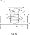
- FIG. 7B the operator may insert self-tapping flutes (132) through threaded through hole (62) until self-tapping flutes (132) contact an outer surface of bone (10).
- the operator may drive rotation of bone screw (130) about its own longitudinal axis (LA) via a driving mechanism and drive recess (not shown) such that self-tapping flutes (132) begin to penetrate bone (10).
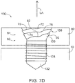
- the operator may further drive rotation of bone screw (130) about its own longitudinal axis (LA) such that first threaded portion (134) suitably engages bone (10), and such that deformable locking threaded portion (138) deforms to the profile of irregular female threading (64) in accordance with the description above.
- a bone screw assembly comprising: (a) a first body, wherein the first body comprises: (i) a proximal portion, (ii) a distal portion, wherein the first body extends from the proximal portion toward the distal portion along a longitudinal axis, wherein the distal portion is configured to pierce bone in response to rotation of the first body about the longitudinal axis, and (iii) a first threaded section, wherein the first threaded section is configured to engage bone; (b) a second body, wherein the second body defines a through hole dimensioned to receive the distal portion of the first body; and (c) a thread locking assembly configured to couple the first body with the second body, wherein the thread locking assembly comprise locking assembly comprises: (i) a first threaded locking section associated with the proximal portion of the first body, (ii) a second threaded locking section associated with the through hole of the second body, wherein the first threaded locking section is configured rotate relative to the second threaded
- Example 1 The bone screw assembly of Example 1, wherein the second threaded locking section is configured to deform the first threaded locking section in response to rotation of the first threaded locking section relative to the second threaded locking section.
- Example 2 The bone screw assembly of Example 2, wherein the second threaded locking section comprises a non-uniform wave configured to deform the first threaded locking section.
- Example 3 The bone screw assembly of Example 3, wherein the second threaded locking section comprises a first helix angle, wherein the non-uniform wave comprises a deviated helix angle.
- Example 5 The bone screw assembly of Example 5, wherein the first portion comprises a first pitch, wherein the second portion comprises a second pitch, wherein the first pitch is different than the second pitch.
- Example 6 The bone screw assembly of Example 6, wherein the first portion of the second threaded locking section is proximal relative to the second portion of the second threaded locking section.
- Example 7 The bone screw assembly of Example 7, wherein the first threaded locking section is configured to traverse the first portion of the second threaded locking section without deforming, wherein the first threaded locking section is configured to traverse the second pitch while deforming.
- Example 9 The bone screw assembly of Example 9, wherein the first threaded locking section is configured to traverse the first portion of the second threaded locking section without deforming, wherein the first threaded locking section is configured to traverse the second pitch while deforming.
- Example 13 The bone screw assembly of Example 13, wherein the prosthesis comprises an acetabular component of a hip replacement assembly.
- a bone screw assembly comprising: (a) a first body, wherein the first body comprises: (i) a proximal portion, (ii) a distal portion, wherein the first body extends from the proximal portion toward the distal portion along a longitudinal axis, wherein the distal portion is configured to pierce bone in response to rotation of the first body about the longitudinal axis, and (iii) a first threaded section, wherein the first threaded section is configured to engage bone; (b) a second body, wherein the second body defines a through hole dimensioned to receive the distal portion of the first body; and (c) a thread locking assembly configured to couple the first body with the second body, wherein the thread locking assembly comprise locking assembly comprises: (i) a first threaded locking section associated with the proximal portion of the first body, (ii) a second threaded locking section associated with the through hole of the second body, wherein the first threaded locking section is configured rotate relative to the second threaded
- Example 18 The bone screw assembly of Example 18, wherein the irregular female threading comprises a wave pattern.
- a bone screw assembly comprising: (a) a first body, wherein the first body comprises a first threaded section, wherein the first threaded section is configured to engage bone; (b) a second body, wherein the second body defines a through hole dimensioned to receive a portion of the first body, wherein the through hole extends along a longitudinal axis; and (c) a thread locking assembly configured to couple the first body with the second body, wherein the thread locking assembly comprise locking assembly comprises: (i) a first threaded locking section associated with the proximal portion of the first body, (ii) a second threaded locking section associated with the through hole of the second body, wherein the first threaded locking section is configured rotate relative to the second threaded locking section in order to mesh with the second thread locking section, wherein the second threaded locking section is not axisymmetric about the longitudinal axis.
Landscapes
- Health & Medical Sciences (AREA)
- Orthopedic Medicine & Surgery (AREA)
- Life Sciences & Earth Sciences (AREA)
- Surgery (AREA)
- Animal Behavior & Ethology (AREA)
- Veterinary Medicine (AREA)
- Public Health (AREA)
- Engineering & Computer Science (AREA)
- Biomedical Technology (AREA)
- Heart & Thoracic Surgery (AREA)
- General Health & Medical Sciences (AREA)
- Molecular Biology (AREA)
- Medical Informatics (AREA)
- Nuclear Medicine, Radiotherapy & Molecular Imaging (AREA)
- Neurology (AREA)
- Cardiology (AREA)
- Oral & Maxillofacial Surgery (AREA)
- Transplantation (AREA)
- Vascular Medicine (AREA)
- Surgical Instruments (AREA)
- Prostheses (AREA)
Abstract
Description
- Medical screws or orthopedic (bone) screws may be used in orthopedic procedures to help immobilize bone segments of a fractured bone to promote healing. In some instances, bone screws are used in conjunction with a bone plate to help further immobilize segments of fractured bones. In some other instances, bone screws may be used to attach a prosthesis to a bone, such as an acetabular component of a hip joint replacement prosthesis or a tibia component of a total knee replacement prosthesis. Once the bone screw is deployed, it may be desirable to ensure that the bone screw remains suitably secured to its surroundings. Therefore, a bone screw may be configured to engage and secure to both a bone, and, if present, a bone plate or other prosthesis component. Bone screws may have multiple threaded regions configured to engage different elements. In such instances, one threaded region may be configured to engage and couple with a bone, while a second threaded region may be configured to engage and couple with a complementary threading located on the bone plate or other prosthesis.
- Three-dimensional (3D) printing is an additive printing process used to make three-dimensional solid objects from a digital model. 3D printing may be used in various processes including but not limited to rapid product prototyping, product manufacturing, mold generation, and mold master generation. 3D printing techniques are considered additive processes because they involve the application of successive layers of material. This is unlike traditional machining processes, which often rely upon the removal of material to create the final object. Various materials may be used in 3D printing. For example, materials such as polymide, alumide, titanium, or thermoplastic polyurethane may be used in 3D printing. Some 3D printing techniques utilize powder as the basic material, then transform the powder into a desired shape or structures to form a product. For example, laser sintering involves applying successive thin layers of powder, one layer on top of the next. Between application of each layer of powder, a laser travels over desired portions of the current powder layer and sinters targeted powder together, eventually forming the desired shape or structure. Once complete, the final product may be removed from the unsintered powder.
- While various kinds of bone screws and bone plates have been made and used, it is believed that no one prior to the inventor(s) has made or used the invention described in the appended claims.
- While the specification concludes with claims which particularly point out and distinctly claim this technology, it is believed this technology will be better understood from the following description of certain examples taken in conjunction with the accompanying drawings, in which like reference numerals identify the same elements and in which:
-
FIG. 1 depicts an elevational side view of a bone plate attached a bone via bone screws to immobilize fracture segments of the bone, where the bone is transparent for purposes of clarity; -
FIG. 2 depicts a perspective view of an exemplary hip replacement prosthesis; -
FIG. 3 depicts an exploded perspective view of the exemplary hip replacement prosthesis ofFIG. 2 ; -
FIG. 4 depicts a partially exploded perspective view of the hip replacement prosthesis ofFIG. 2 partially attached to a patient; -
FIG. 5 depicts a perspective view of an exemplary bone screw; -
FIG. 6 depicts a cross-sectional front view of the bone screw ofFIG. 5 attached to the bone plate ofFIG. 1 ; -
FIG. 7A depicts a cross-sectional front view of an alternative bone screw aligned for coupling with an alternative bone plate attached to the bone ofFIG. 1 ; -
FIG. 7B depicts a cross-sectional front view of the bone screw and bone plate ofFIG. 7A , where the bone screw is initially inserted into the bone plate to make initial contact with the bone ofFIG. 1 ; -
FIG. 7C depicts a cross-sectional front view of the bone screw and bone plate ofFIG. 7A , where the bone screw is further inserted into the bone plate and the bone ofFIG. 1 ; and -
FIG. 7D depicts a cross-sectional front view of the bone screw and bone plate ofFIG. 7A , where the bone screw is coupled with the bone plate and fully inserted into the bone ofFIG. 1 . - The drawings are not intended to be limiting in any way, and it is contemplated that various embodiments of the technology may be carried out in a variety of other ways, including those not necessarily depicted in the drawings. The accompanying drawings incorporated in and forming a part of the specification illustrate several aspects of the present technology, and together with the description serve to explain the principles of the technology; it being understood, however, that this technology is not limited to the precise arrangements shown.
- The following description of certain examples of the technology should not be used to limit its scope. Other examples, features, aspects, embodiments, and advantages of the technology will become apparent to those skilled in the art from the following description, which is by way of illustration, one of the best modes contemplated for carrying out the technology. As will be realized, the technology described herein is capable of other different and obvious aspects, all without departing from the technology. Accordingly, the drawings and descriptions should be regarded as illustrative in nature and not restrictive.
- As mentioned above, bone screws may be used to immobilize fragments of fractured bones, attach various prostheses to corresponding anatomy, or for any other suitable purposes as would be apparent to one having ordinary skill in the art in view of the teachings herein. In some instances, bone screws may be used by themselves to immobilize and help heal fractures. However, in other instances bone screws may be used in conjunction with a bone plate or other structure to provide additional structural support.
-
FIG. 1 shows the use of a plurality of bone screws (30) in conjunction with a bone plate (20) to immobilize fractures (12) on a bone (10). Bone plate (20) is dimensioned to abut against or extend along the profile of the exterior surface of bone (10). Bone plate (20) may be used in conjunction with bone screws (30) to provide structural support for bone (10). It should be understood that different anatomical locations demand different shapes and sizes of bone plates (20). Therefore, bone plate (20) may have any suitable shape, size, and/or profile configured to engage a corresponding anatomical structure of bone (10) as would be apparent to one having ordinary skill in the art in view of the teachings herein. For example, bone plate (20) may be dimensioned for use on the jaw, on the pelvis, on the forearm, and/or around joints of a patient. Similarly, bone screw (30) may have any suitable shape, size, and/or profile as needed. - As best seen in
FIG. 5 , an exemplary bone screw (30) includes self-tapping flutes (32) at the distal end, a first threaded portion (34), and head (35). Self-tapping flutes (32) are dimensioned and configured to penetrate and drive into bone (10) in response to rotation of bone screw (30) about its own longitudinal axis. First threaded portion (34) is configured to further engage bone (10) as bone screw (30) is driven about its own longitudinal axis. In particular, first threaded portion (34) is configured to engage bone (10) in order to help fix screw (30) relative to bone (10) when bone screw (30) is suitably deployed. - Head (35) includes a locking threaded portion (38). As best seen in
FIG. 6 , when bone screw (30) is suitably coupled with bone (10) and bone plate (20), locking threaded portion (38) may suitably mesh with internal female threading (24) of bone plate (20) in order to help fixate bone screw (30) relative to bone plate (20). Because bone screw (30) includes first threaded portion (34) configured to help fixate bone screw (30) relative to bone (10), and because bone screw (30) includes locking threaded portion (38) configured to help bone screw (30) fixate to bone plate (20), bone screw (30) may be used to help fixate bone plate (20) relative to bone (10). The threaded coupling between bone screw (30) and bone plate (20) allows bone screw (30) to couple with bone plate (20) at a suitable torque value. In other words, bone screw (30) may couple or decouple with bone plate (20) when bone screw (30) and/or bone plate (20) are torqued about the longitudinal axis of threading at the suitable torque value. - Head (35) also defines a drive recess (36). Drive recess (36) is dimensioned to couple with a driving tool (e.g., screwdriver, driving key, etc.) that may rotate bone screw (30) about its own longitudinal axis. Therefore, a driving tool may engage bone screw (30) at drive recess (36) in order to suitably torque bone screw (30) about its own longitudinal axis in accordance with the description herein. Drive recess (36) may allow the suitable torque required to couple bone screw (30) with bone plate (20) via threading (24, 38) to be increased, which may lead to a greater coupling strength.
- As mentioned above, bone plate (20) may be affixed to bone (10) by bone screws (30). In particular, various bone screws (30) may be inserted into corresponding through holes (22) defined by bone plate (20). Bone screws (30) may then be driven into engagement with bone (10) until a head (35) of bone screws (30) meshes with bone plate (20) in accordance with the description herein. As best seen in
FIG. 1 , bone screws (30) may also extend through fractures (12) of bone (10) to also help immobilize bone (10). Therefore, bone plate (20) and bone screws (30) may help stabilize fractures (12) of bone (10) relative to each other, while bone plate (20) may help provide additional structural support. - As mentioned above, bone screws (30) may also be used to attach certain prosthesis implants to bones.
FIGS. 2-3 show an exemplary hip replacement prosthesis (40) including an acetabular component (42) defining threaded through holes (44), a plastic liner (46), and a femoral component (48). As shown inFIG. 4 , acetabular component (42) of hip replacement prosthesis (40) may be affixed to pelvis (14) by bone screws (30). In particular, bone screws (30) may be inserted through threaded through holes (44) defined by the internal cavity of acetabular component (42). Bone screws (30) may then be driven into engagement with pelvis (14) until head (35) of bone screws (30) engage threaded through holes (44). Threaded through holes (44) may have internal female threading substantially similar to threading (24) described above for bone plate (20). Therefore, bone screw (30) may affix to pelvis (14) via first threaded portion (34), while bone screw (30) may also affix to acetabular component (42) via locking threaded portion (38) and threaded through holes (44). In other words, bone screws (30) may help fixate acetabular component (42) to pelvis (14). - When suitably implanted, femoral component (48) may move relative to acetabular component (42). Additionally, when suitably implanted, femoral component (48) and acetabular component (42) may transfer loads between each other. Therefore, bone screws (30) may help keep acetabular component (42) fixed relative to pelvis (14) in order to accommodate movement, as well as weight transfers between femoral component (48) and acetabular component (42).
- It should be understood that acetabular component (42) is just one exemplary prosthesis that bone screw (30) may be used in conjunction with. Bone screw (30) may be used with any other suitable exemplary prostheses having threaded through holes as would be apparent to one having ordinary skill in the art in view of the teachings herein. For instance, bone screws (30) may be utilized to fixate a tibia prosthesis component during a total knee replacement.
- The term "bone plate" should be interpreted as any structural body that may couple with any suitable anatomy via a bone screw (30). Therefore, as used herein, the term "bone plate" may include various prosthesis components configured to couple with a bone, such as a tibia prosthesis component of a total knee replacement, an acetabular component of a hip replacement, etc.
- As mentioned above, while first threaded portion (34) may engage bone (10) to fixate bone screw (30) with bone (10), locking threaded portion (38) may suitably mesh with internal female threading (24) of bone plate (20) in order to help fixate bone screw (30) relative to bone plate (20). As also mentioned above, bone screw (30) may couple or decouple with threaded through holes (22) when bone screws (30) are torqued relative to bone plate (20) about the longitudinal axis of threading at the suitable torque value.
- Once bone screw (30) is suitably coupled with bone plate (20) such that bone plate (20) is affixed relative to bone (10), it may be desirable to keep bone screws (30) suitably secured to bone plate (20). However, in some instances, the engagement between internal female threading (24) of bone plate (20) and locking threaded portion (38) of bone screw (30) may eventually loosen. If engagement between internal female threading (24) and locking threaded portion (38) loosens, bone plate (20) may no longer be fixated relative to bone (10). It may therefore be desirable to prevent bone screws (30) from disassociating with bone plate (20) once suitably coupled with each other.
-
FIGS. 7A-7D show an alternative bone screw (130) and an alternative bone plate (60) that may be configured to prevent bone screw (130) from disassociating with bone plate (60) once suitably coupled with each other. Bone screw (130) and bone plate (60) may be used in replacement of bone screw (30) and bone plate (20) described above. Therefore, bone screw (130) may be substantially similar to bone screw (30) described above, while bone plate (60) may be substantially similar to bone plate (20) described above, except for the differences described below. - Bone screw (130) includes self-tapping flutes (132) at the distal end, a first threaded portion (134), and head (135), which are substantially similar to self-tapping flutes (32), first threaded portion (34), and head (35) described above, with differences elaborated below. Therefore, self-tapping flutes (132) are dimensioned and configured to penetrate and drive into bone (10) in response to rotation of bone screw (130) about its own longitudinal axis (LA). First threaded portion (134) is configured to further engage bone (10) as bone screw (130) is driven about its own longitudinal axis. In particular, first threaded portion (134) is configured to engage bone (10) in order to help fix bone screw (130) relative to bone (10) when bone screw (130) is suitably deployed.
- Head (135) is substantially similar to head (35) described above, with differences elaborated below. Therefore, head (135) defines a drive recess (not shown) that is substantially similar to drive recess (36) describe above. Head (135) also includes a deformable locking threaded portion (138), which may be similar to locking threaded portion (38), with differences elaborated below. Deformable locking threaded portion (138) is operable to conform to an irregular female threading (64) of bone plate (60) when a suitable torque is applied to bone screw (130) about the longitudinal axis (LA). As deformable locking threaded portion (138) of bone screw (130) deforms, this may help the meshed threading (138, 64) between bone screw (130) and bone plate (60) "bind up," lock, jam, or seize up, thereby requiring a large amount of torque to unscrew deformable locking threaded portion (138) out of irregular female threading (64) of bone plate (60). Seizing, locking, jamming, or binding up of threading (138, 64) may ultimately prevent bone screw (130) from disassociating with bone plate (60) once the two are suitably coupled with each other in accordance with the description herein. Deformable locking threaded portion (138) may be made out of any suitable material as would be apparent to one having ordinary skill in that art in view of the teachings herein. Deformation of locking threaded portion (138) may be elastic or plastic.
- Bone plate (60) includes at least one threaded through hole (62), each defining an irregular female threading (64). Unlike conventional bone plates (20) that have female threading (24) formed from a conventional tapping machine that removes material to form threading (24) in a pure helical configuration, bone plate (60) may be formed from an additive process like 3D printing. Therefore, female threading (64) may be formed by adding layers of material on top of each other incrementally, rather than using a tapping machine that needs to be removed from through hole (62) after forming female threading (64). It should be understood that the female threading (64) described herein may not be subject to formation via conventional tapping processes, due to the presence of intentional structural irregularities in female threading (64) as described herein.
- Irregular female threading (64) has a first female threading portion (70), which connects distally into a second female threading portion (74), which also connects distally into a third female threading portion (80). As will be elaborated below, while female threading portions (70, 74, 80) are continuously connected with each other, female threading portions (70, 74, 80) are not uniform in nature. In other words, if a male threaded member were dimensioned to rotate through first female threading portion (70) in a substantially unimpeded fashion, that same male threaded member would need to be rotated with enough torque to deform itself in order to traverse across second female threading portion (74) and third female threading portion (80).
- Therefore, irregular female threading (64) in not axisymmetric about the longitudinal axis (LA) of bone screw (130) when bone plate (60) and bone screw (130) are suitably coupled. In other words, if irregular female threading (64) were viewed from within the confines of threaded through hole (62) at a location along the longitudinal axis (LA) and female threading (64) was rotated, the appearance of female threading (64) would not appear unchanged. Irregular female threading (64) may have deviations in pitch, may have deviations in helix angles, may have deviations in thread angles, may have deviations in root/crest, and may have any other suitable deviations that would leave to deformation of deformable locking threaded portion (138) as would be apparent to one having ordinary skill in the art in view of the teachings herein.
- A portion of first female threading portion (70) extends along a first axis (94), but also includes a non-uniform wave (72), thereby creating a substantial non-uniform deviation in helix angle. Similarly, a portion of second female threading portion (74) extends along a second axis (96), but also includes a non-uniform wave (76), thereby creating a substantial non-uniform deviation in helix angle. Likewise, a portion of third female threading portion (80) extends along a third axis (98), but also includes a non-uniform wave (82), thereby creating a substantial non-uniform deviation in helix angle. First axis (94) and second axis (96) define a first angle (100) while second axis (96) and third axis (98) define a second, different angle (102). Similarly, first female threading portion (70) and second female threading portion (74) define a first pitch (90), while second female threading portion (74) and third female threading portion (80) define a second, different, pitch (92). First female threading portions (70), second female threading portion (74), and third female threading portion (80) have deviations in thread angles; and may have deviations in root/crest.
- Waves (72, 76, 82), change in pitches (90, 92), and change in angles (100, 102) may interact with deformable locking threaded portion (138) such that once deformable locking threaded portion (138) encounters a wave (72, 76, 82), change in pitch (90, 92), or change in angle (100, 102), the operator must apply enough toque to bone screw (130) about longitudinal axis (LA) in order to deform locking threaded portion (138) of bone screw (130) such that male locking threaded portion (138) may further traverse irregular female threading (64). Once bone screw (130) is fully coupled with bone plate (60), the deformation of deformable male locking threaded portion (138) may conform to the shape of irregular female threading (64). In other words, male locking threaded portion (138) will have a complementary threaded profile as irregular female threading (64). After being suitably coupled, if for some reason bone screw (130) attempts to unscrew or otherwise loosen from bone plate (60), the irregular profile of both female threading (64) and male locking threaded portion (138) will resist rotation of male locking threaded portion (138) out of female threading (64) unless the rotation has enough torque to re-deform or damage male locking threaded portion (138). This resistance to rotation may help prevent bone screws (130) from disassociating with bone plate (60) once suitably coupled with each other.
- In the current example, male locking threaded portion (138) is deformable, while female threading (64) is irregular. However, this is merely optional. In another example, male locking threaded portion (138) may be irregular, while female threading (64) may be deformable such that insertion of male locking threaded portion (138) deforms female threading (64). Of course, both male threading (138) and female threading (64) may have irregularities that in turn deform each other during coupling. In some variations, irregular female threading (64) may slightly deform while male threading (138) may not deform at all. In such cases, the deforming irregularities of female threading (64) may provide interferences with the non-deforming regular male threading (138), thereby effectively locking the threads together through an interference fit.
- In the current example, bone plate (60) is entirely 3D printed while forming irregular female threading (64). However, this is merely optional. For instance, bone plate (60) may start as regular plate with larger screw holes preformed. Then, irregularities of female threading (64) may be subsequently added via the additive process of 3D printing. OF course, irregularities of female threading (64) may be formed utilizing any other suitably means as would be apparent to one having ordinary skill in the art in view of the teachings herein.
-
FIGS 7A-7D show an exemplary use of bone screw (130) and bone plate (60). First, the operator may place bone plate (60) at a sufficient location relative to bone (10). Next, the operator may align bone screw (130) relative to bone plate (60) such that self-tapping flutes (132) are directly adjacent to threaded through hole (62). Next, as shown inFIG. 7B , the operator may insert self-tapping flutes (132) through threaded through hole (62) until self-tapping flutes (132) contact an outer surface of bone (10). Next, as shown inFIG. 7C , the operator may drive rotation of bone screw (130) about its own longitudinal axis (LA) via a driving mechanism and drive recess (not shown) such that self-tapping flutes (132) begin to penetrate bone (10). Next, as shown inFIG. 7D the operator may further drive rotation of bone screw (130) about its own longitudinal axis (LA) such that first threaded portion (134) suitably engages bone (10), and such that deformable locking threaded portion (138) deforms to the profile of irregular female threading (64) in accordance with the description above. - The following examples relate to various non-exhaustive ways in which the teachings herein may be combined or applied. It should be understood that the following examples are not intended to restrict the coverage of any claims that may be presented at any time in this application or in subsequent filings of this application. No disclaimer is intended. The following examples are being provided for nothing more than merely illustrative purposes. It is contemplated that the various teachings herein may be arranged and applied in numerous other ways. It is also contemplated that some variations may omit certain features referred to in the below examples. Therefore, none of the aspects or features referred to below should be deemed critical unless otherwise explicitly indicated as such at a later date by the inventors or by a successor in interest to the inventors. If any claims are presented in this application or in subsequent filings related to this application that include additional features beyond those referred to below, those additional features shall not be presumed to have been added for any reason relating to patentability.
- A bone screw assembly, comprising: (a) a first body, wherein the first body comprises: (i) a proximal portion, (ii) a distal portion, wherein the first body extends from the proximal portion toward the distal portion along a longitudinal axis, wherein the distal portion is configured to pierce bone in response to rotation of the first body about the longitudinal axis, and (iii) a first threaded section, wherein the first threaded section is configured to engage bone; (b) a second body, wherein the second body defines a through hole dimensioned to receive the distal portion of the first body; and (c) a thread locking assembly configured to couple the first body with the second body, wherein the thread locking assembly comprise locking assembly comprises: (i) a first threaded locking section associated with the proximal portion of the first body, (ii) a second threaded locking section associated with the through hole of the second body, wherein the first threaded locking section is configured rotate relative to the second threaded locking section in order to mesh with the second thread locking section, wherein either the first threaded locking section or the second threaded locking section is configured to deform the other in response to rotation of the first threaded locking section relative to the second threaded locking section.
- The bone screw assembly of Example 1, wherein the second threaded locking section is configured to deform the first threaded locking section in response to rotation of the first threaded locking section relative to the second threaded locking section.
- The bone screw assembly of Example 2, wherein the second threaded locking section comprises a non-uniform wave configured to deform the first threaded locking section.
- The bone screw assembly of Example 3, wherein the second threaded locking section comprises a first helix angle, wherein the non-uniform wave comprises a deviated helix angle.
- The bone screw assembly of any one or more of Examples 2 through 4, wherein the second threaded locking section comprises a first portion and a second portion continuously connected with each other.
- The bone screw assembly of Example 5, wherein the first portion comprises a first pitch, wherein the second portion comprises a second pitch, wherein the first pitch is different than the second pitch.
- The bone screw assembly of Example 6, wherein the first portion of the second threaded locking section is proximal relative to the second portion of the second threaded locking section.
- The bone screw assembly of Example 7, wherein the first threaded locking section is configured to traverse the first portion of the second threaded locking section without deforming, wherein the first threaded locking section is configured to traverse the second pitch while deforming.
- The bone screw assembly of any one or more of Examples 5 through 8, wherein the first portion comprises a first helix angle, wherein the second portion comprises a second helix angle.
- The bone screw assembly of Example 9, wherein the first threaded locking section is configured to traverse the first portion of the second threaded locking section without deforming, wherein the first threaded locking section is configured to traverse the second pitch while deforming.
- The bone screw assembly of any one or more of Examples 5 through 10, wherein the first portion comprises a first thread angle, wherein the second portion comprises a second thread angle, wherein the second thread angle is different than the first thread angle.
- The bone screw assembly of any one or more of Examples 5 through 11, wherein the first portion comprises a first crest-root distance, wherein the second portion comprises a second crest-root distance, wherein the second crest-root distance is different than the first crest-root distance.
- The bone screw assembly of any one or more of Examples 1 through 12, wherein the second body comprises a prosthesis.
- The bone screw assembly of Example 13, wherein the prosthesis comprises an acetabular component of a hip replacement assembly.
- The bone screw assembly of any one or more of Examples 1 through 14, wherein the proximal portion of the first body defines a drive recess.
- The bone screw assembly of any one or more of Examples 1 through 15, wherein the distal portion of the first body comprises a self-tapping flute.
- The bone screw assembly of any one or more of Examples 1 through 16, wherein the second body comprises a bone plate.
- A bone screw assembly, comprising: (a) a first body, wherein the first body comprises: (i) a proximal portion, (ii) a distal portion, wherein the first body extends from the proximal portion toward the distal portion along a longitudinal axis, wherein the distal portion is configured to pierce bone in response to rotation of the first body about the longitudinal axis, and (iii) a first threaded section, wherein the first threaded section is configured to engage bone; (b) a second body, wherein the second body defines a through hole dimensioned to receive the distal portion of the first body; and (c) a thread locking assembly configured to couple the first body with the second body, wherein the thread locking assembly comprise locking assembly comprises: (i) a first threaded locking section associated with the proximal portion of the first body, (ii) a second threaded locking section associated with the through hole of the second body, wherein the first threaded locking section is configured rotate relative to the second threaded locking section in order to mesh with the second thread locking section, wherein the second threaded locking section comprises an irregular female threading, wherein either the first threaded locking section is configured to deform the second threaded locking section or the second threaded locking section is configured to deform the first threaded locking section as the first threaded locking section rotates relative to the second threaded locking section.
- The bone screw assembly of Example 18, wherein the irregular female threading comprises a wave pattern.
- A bone screw assembly, comprising: (a) a first body, wherein the first body comprises a first threaded section, wherein the first threaded section is configured to engage bone; (b) a second body, wherein the second body defines a through hole dimensioned to receive a portion of the first body, wherein the through hole extends along a longitudinal axis; and (c) a thread locking assembly configured to couple the first body with the second body, wherein the thread locking assembly comprise locking assembly comprises: (i) a first threaded locking section associated with the proximal portion of the first body, (ii) a second threaded locking section associated with the through hole of the second body, wherein the first threaded locking section is configured rotate relative to the second threaded locking section in order to mesh with the second thread locking section, wherein the second threaded locking section is not axisymmetric about the longitudinal axis.
- It should also be understood that any one or more of the teachings, expressions, embodiments, examples, etc. described herein may be combined with any one or more of the other teachings, expressions, embodiments, examples, etc. that are described herein. The above-described teachings, expressions, embodiments, examples, etc. should therefore not be viewed in isolation relative to each other. Various suitable ways in which the teachings herein may be combined will be readily apparent to those of ordinary skill in the art in view of the teachings herein. Such modifications and variations are intended to be included within the scope of the claims.
- It should be appreciated that any patent, publication, or other disclosure material, in whole or in part, that is said to be incorporated by reference herein is incorporated herein only to the extent that the incorporated material does not conflict with existing definitions, statements, or other disclosure material set forth in this disclosure. As such, and to the extent necessary, the disclosure as explicitly set forth herein supersedes any conflicting material incorporated herein by reference. Any material, or portion thereof, that is said to be incorporated by reference herein, but which conflicts with existing definitions, statements, or other disclosure material set forth herein will only be incorporated to the extent that no conflict arises between that incorporated material and the existing disclosure material.
- Having shown and described various embodiments of the present invention, further adaptations of the methods and systems described herein may be accomplished by appropriate modifications by one of ordinary skill in the art without departing from the scope of the present invention. Several of such potential modifications have been mentioned, and others will be apparent to those skilled in the art. For instance, the examples, embodiments, geometries, materials, dimensions, ratios, steps, and the like discussed above are illustrative and are not required. Accordingly, the scope of the present invention should be considered in terms of the following claims and is understood not to be limited to the details of structure and operation shown and described in the specification and drawings.
Claims (20)
- A bone screw assembly, comprising:(a) a first body, wherein the first body comprises:(i) a proximal portion,(ii) a distal portion, wherein the first body extends from the proximal portion toward the distal portion along a longitudinal axis, wherein the distal portion is configured to pierce bone in response to rotation of the first body about the longitudinal axis, and(iii) a first threaded section, wherein the first threaded section is configured to engage bone;(b) a second body, wherein the second body defines a through hole dimensioned to receive the distal portion of the first body; and(c) a thread locking assembly configured to couple the first body with the second body, wherein the thread locking assembly comprise locking assembly comprises:(i) a first threaded locking section associated with the proximal portion of the first body,(ii) a second threaded locking section associated with the through hole of the second body, wherein the first threaded locking section is configured rotate relative to the second threaded locking section in order to mesh with the second thread locking section, wherein either the first threaded locking section or the second threaded locking section is configured to deform the other in response to rotation of the first threaded locking section relative to the second threaded locking section.
- The bone screw assembly of claim 1, wherein the second threaded locking section is configured to deform the first threaded locking section in response to rotation of the first threaded locking section relative to the second threaded locking section.
- The bone screw assembly of claim 2, wherein the second threaded locking section comprises a non-uniform wave configured to deform the first threaded locking section.
- The bone screw assembly of claim 3, wherein the second threaded locking section comprises a first helix angle, wherein the non-uniform wave comprises a deviated helix angle.
- The bone screw assembly of claim 2, wherein the second threaded locking section comprises a first portion and a second portion continuously connected with each other.
- The bone screw assembly of claim 5, wherein the first portion comprises a first pitch, wherein the second portion comprises a second pitch, wherein the first pitch is different than the second pitch.
- The bone screw assembly of claim 6, wherein the first portion of the second threaded locking section is proximal relative to the second portion of the second threaded locking section.
- The bone screw assembly of claim 7, wherein the first threaded locking section is configured to traverse the first portion of the second threaded locking section without deforming, wherein the first threaded locking section is configured to traverse the second pitch while deforming.
- The bone screw assembly of claim 5, wherein the first portion comprises a first helix angle, wherein the second portion comprises a second helix angle.
- The bone screw assembly of claim 9, wherein the first threaded locking section is configured to traverse the first portion of the second threaded locking section without deforming, wherein the first threaded locking section is configured to traverse the second pitch while deforming.
- The bone screw assembly of claim 5, wherein the first portion comprises a first thread angle, wherein the second portion comprises a second thread angle, wherein the second thread angle is different than the first thread angle.
- The bone screw assembly of claim 5, wherein the first portion comprises a first crest-root distance, wherein the second portion comprises a second crest-root distance, wherein the second crest-root distance is different than the first crest-root distance.
- The bone screw assembly of claim 1, wherein the second body comprises a prosthesis.
- The bone screw assembly of claim 13, wherein the prosthesis comprises an acetabular component of a hip replacement assembly.
- The bone screw assembly of claim 1, wherein the proximal portion of the first body defines a drive recess.
- The bone screw assembly of claim 1, wherein the distal portion of the first body comprises a self-tapping flute.
- The bone screw assembly of claim 1, wherein the second body comprises a bone plate.
- A bone screw assembly, comprising:(a) a first body, wherein the first body comprises:(i) a proximal portion,(ii) a distal portion, wherein the first body extends from the proximal portion toward the distal portion along a longitudinal axis, wherein the distal portion is configured to pierce bone in response to rotation of the first body about the longitudinal axis, and(iii) a first threaded section, wherein the first threaded section is configured to engage bone;(b) a second body, wherein the second body defines a through hole dimensioned to receive the distal portion of the first body; and(c) a thread locking assembly configured to couple the first body with the second body, wherein the thread locking assembly comprise locking assembly comprises:(i) a first threaded locking section associated with the proximal portion of the first body,(ii) a second threaded locking section associated with the through hole of the second body, wherein the first threaded locking section is configured rotate relative to the second threaded locking section in order to mesh with the second thread locking section, wherein the second threaded locking section comprises an irregular female threading, wherein either the first threaded locking section is configured to deform the second threaded locking section or the second threaded locking section is configured to deform the first threaded locking section as the first threaded locking section rotates relative to the second threaded locking section.
- The bone screw assembly of claim 18, wherein the irregular female threading comprises a wave pattern.
- A bone screw assembly, comprising:(a) a first body, wherein the first body comprises a first threaded section, wherein the first threaded section is configured to engage bone;(b) a second body, wherein the second body defines a through hole dimensioned to receive a portion of the first body, wherein the through hole extends along a longitudinal axis; and(c) a thread locking assembly configured to couple the first body with the second body, wherein the thread locking assembly comprise locking assembly comprises:(i) a first threaded locking section associated with the proximal portion of the first body,(ii) a second threaded locking section associated with the through hole of the second body, wherein the first threaded locking section is configured rotate relative to the second threaded locking section in order to mesh with the second thread locking section, wherein the second threaded locking section is not axisymmetric about the longitudinal axis.
Applications Claiming Priority (1)
| Application Number | Priority Date | Filing Date | Title |
|---|---|---|---|
| US16/182,829 US11039866B2 (en) | 2018-11-07 | 2018-11-07 | Bone screw with 3D printed thread locking feature |
Publications (2)
| Publication Number | Publication Date |
|---|---|
| EP3649972A1 true EP3649972A1 (en) | 2020-05-13 |
| EP3649972B1 EP3649972B1 (en) | 2024-07-24 |
Family
ID=68502956
Family Applications (1)
| Application Number | Title | Priority Date | Filing Date |
|---|---|---|---|
| EP19207775.8A Active EP3649972B1 (en) | 2018-11-07 | 2019-11-07 | Bone screw with 3d printed thread locking feature |
Country Status (4)
| Country | Link |
|---|---|
| US (2) | US11039866B2 (en) |
| EP (1) | EP3649972B1 (en) |
| JP (1) | JP7463080B2 (en) |
| CN (1) | CN111150480B (en) |
Cited By (2)
| Publication number | Priority date | Publication date | Assignee | Title |
|---|---|---|---|---|
| IT202100019154A1 (en) * | 2021-07-20 | 2023-01-20 | Tsq Global S R L | DEVICE FOR OSTEOSYNTHESIS |
| IT202100019172A1 (en) * | 2021-07-20 | 2023-01-20 | Tsq Global S R L | DEVICE FOR OSTEOSYNTHESIS |
Families Citing this family (18)
| Publication number | Priority date | Publication date | Assignee | Title |
|---|---|---|---|---|
| WO2015134750A1 (en) | 2014-03-06 | 2015-09-11 | University Of British Columbia | Shape adaptable intramedullary fixation device |
| EP4245233A3 (en) | 2014-10-14 | 2023-12-06 | The University of British Columbia | Systems for intramedullary bone fixation |
| EP4516267A3 (en) | 2018-03-28 | 2025-05-21 | SI-Bone, Inc. | Threaded implants and methods of use across bone segments |
| EP3866712A1 (en) | 2018-10-17 | 2021-08-25 | Curvafix, Inc. | Intramedullary fixation device |
| US11832856B2 (en) * | 2018-10-17 | 2023-12-05 | The University Of British Columbia | Bone-fixation device and system |
| US11039866B2 (en) | 2018-11-07 | 2021-06-22 | Cilag Gmbh International | Bone screw with 3D printed thread locking feature |
| US11369419B2 (en) | 2019-02-14 | 2022-06-28 | Si-Bone Inc. | Implants for spinal fixation and or fusion |
| JP2022520101A (en) | 2019-02-14 | 2022-03-28 | エスアイ-ボーン・インコーポレイテッド | Implants for spinal fixation and / or fusion |
| WO2021102429A1 (en) | 2019-11-21 | 2021-05-27 | Si-Bone Inc. | Rod coupling assemblies for bone stabilization constructs |
| US11672570B2 (en) | 2019-11-27 | 2023-06-13 | Si-Bone Inc. | Bone stabilizing implants and methods of placement across SI Joints |
| WO2021119126A1 (en) | 2019-12-09 | 2021-06-17 | Si-Bone Inc. | Sacro-iliac joint stabilizing implants and methods of implantation |
| AU2021397743A1 (en) | 2020-12-09 | 2023-06-22 | Si-Bone Inc. | Sacro-iliac joint stabilizing implants and methods of implantation |
| EP4440505A4 (en) | 2021-12-03 | 2025-11-19 | Si Bone Inc | FUSION CAGES AND PROCEDURES FOR SAFETY JOINT STABILIZATION |
| US12588930B2 (en) | 2022-02-04 | 2026-03-31 | Curvafix, Inc. | Devices, systems, and methods of use for delivery of materials in combination with intramedullary devices |
| DE102022106581B4 (en) * | 2022-03-21 | 2026-05-13 | Medical Magnesium GmbH | Osteosynthesis system with bone plate and bone anchor made of magnesium alloys |
| USD1115031S1 (en) * | 2022-09-08 | 2026-02-24 | Mirus Llc | Locking screw |
| WO2025038769A1 (en) | 2023-08-15 | 2025-02-20 | Si-Bone Inc. | Pelvic stabilization implants, methods of use and manufacture |
| KR20250153358A (en) * | 2024-04-17 | 2025-10-27 | 국립암센터 | Assemble-type Patient-Specific Implant and Method for Manufacturing Thereof |
Citations (6)
| Publication number | Priority date | Publication date | Assignee | Title |
|---|---|---|---|---|
| US6974461B1 (en) * | 1999-09-14 | 2005-12-13 | Dietmar Wolter | Fixation system for bones |
| EP2614787A1 (en) * | 2012-01-16 | 2013-07-17 | Carbofix Orthopedics Ltd. | Multi-axial bone plate fixation |
| US20140271029A1 (en) * | 2013-03-14 | 2014-09-18 | Coorstek Medical, LLC | Polyaxial locking interface |
| US20140330320A1 (en) * | 2011-05-17 | 2014-11-06 | Dietmar Wolter | Bone Plate |
| US20170231673A1 (en) * | 2014-07-09 | 2017-08-17 | National University Corporation Nagoya University | Locking Plate System for Treatment of Fracture of Distal Radius |
| US20180049788A1 (en) * | 2016-08-17 | 2018-02-22 | Globus Medical, Inc. | Volar distal radius stabilization system |
Family Cites Families (8)
| Publication number | Priority date | Publication date | Assignee | Title |
|---|---|---|---|---|
| US8518090B2 (en) * | 2010-10-05 | 2013-08-27 | Acumed Llc | Fastener with serrated thread for attachment to a bone plate at a selectable angle |
| WO2007014192A2 (en) | 2005-07-25 | 2007-02-01 | Smith & Nephew, Inc. | Systems and methods for using polyaxial plates |
| US20070142921A1 (en) | 2005-12-21 | 2007-06-21 | Lewis Paul Peter P | Acetabular cup with rigid fasteners |
| WO2010027478A1 (en) * | 2008-09-08 | 2010-03-11 | Moed Berton R | Locking screw system |
| US9113970B2 (en) * | 2010-03-10 | 2015-08-25 | Orthohelix Surgical Designs, Inc. | System for achieving selectable fixation in an orthopedic plate |
| US11013541B2 (en) * | 2018-04-30 | 2021-05-25 | DePuy Synthes Products, Inc. | Threaded locking structures for affixing bone anchors to a bone plate, and related systems and methods |
| US11039866B2 (en) | 2018-11-07 | 2021-06-22 | Cilag Gmbh International | Bone screw with 3D printed thread locking feature |
| US11944360B2 (en) * | 2019-06-11 | 2024-04-02 | DePuy Synthes Products, Inc. | Deformable threaded locking structures, and related systems and methods |
-
2018
- 2018-11-07 US US16/182,829 patent/US11039866B2/en active Active
-
2019
- 2019-11-06 JP JP2019201284A patent/JP7463080B2/en active Active
- 2019-11-06 CN CN201911104986.6A patent/CN111150480B/en active Active
- 2019-11-07 EP EP19207775.8A patent/EP3649972B1/en active Active
-
2021
- 2021-05-26 US US17/330,502 patent/US11672577B2/en active Active
Patent Citations (6)
| Publication number | Priority date | Publication date | Assignee | Title |
|---|---|---|---|---|
| US6974461B1 (en) * | 1999-09-14 | 2005-12-13 | Dietmar Wolter | Fixation system for bones |
| US20140330320A1 (en) * | 2011-05-17 | 2014-11-06 | Dietmar Wolter | Bone Plate |
| EP2614787A1 (en) * | 2012-01-16 | 2013-07-17 | Carbofix Orthopedics Ltd. | Multi-axial bone plate fixation |
| US20140271029A1 (en) * | 2013-03-14 | 2014-09-18 | Coorstek Medical, LLC | Polyaxial locking interface |
| US20170231673A1 (en) * | 2014-07-09 | 2017-08-17 | National University Corporation Nagoya University | Locking Plate System for Treatment of Fracture of Distal Radius |
| US20180049788A1 (en) * | 2016-08-17 | 2018-02-22 | Globus Medical, Inc. | Volar distal radius stabilization system |
Cited By (2)
| Publication number | Priority date | Publication date | Assignee | Title |
|---|---|---|---|---|
| IT202100019154A1 (en) * | 2021-07-20 | 2023-01-20 | Tsq Global S R L | DEVICE FOR OSTEOSYNTHESIS |
| IT202100019172A1 (en) * | 2021-07-20 | 2023-01-20 | Tsq Global S R L | DEVICE FOR OSTEOSYNTHESIS |
Also Published As
| Publication number | Publication date |
|---|---|
| US20200138492A1 (en) | 2020-05-07 |
| JP7463080B2 (en) | 2024-04-08 |
| CN111150480B (en) | 2024-08-02 |
| EP3649972B1 (en) | 2024-07-24 |
| US11039866B2 (en) | 2021-06-22 |
| US20210346070A1 (en) | 2021-11-11 |
| JP2020075127A (en) | 2020-05-21 |
| CN111150480A (en) | 2020-05-15 |
| US11672577B2 (en) | 2023-06-13 |
| BR102019022704A2 (en) | 2020-05-26 |
Similar Documents
| Publication | Publication Date | Title |
|---|---|---|
| US11672577B2 (en) | Bone screw with 3D printed thread locking feature | |
| US20230190345A1 (en) | Proximal humeral stabilization system | |
| JP7829589B2 (en) | Fastening devices, arthroplasty implants, systems, and methods | |
| US9011504B2 (en) | Apparatus and method for use in the treatment of hammertoe | |
| EP3381383B1 (en) | Proximal humeral stabilization system | |
| EP2613721B1 (en) | Proximal interphalangeal fusion device | |
| US8529611B2 (en) | Distal interphalangeal fusion method and device | |
| JP7817260B2 (en) | Fastening Devices, Systems, and Methods | |
| CA2978697A1 (en) | Shape adaptable intramedullary fixation device | |
| EP3801317A1 (en) | Ankle fusion system with expandable spacer | |
| JP2005066333A (en) | Acetabular cup assembly, total hip replacement system, method of manufacturing acetabular cup assembly, and method of attaching acetabular liner to acetabular shell | |
| US20110257758A1 (en) | Splined tapered modular distal stem with proximal porous coating | |
| WO1985002535A1 (en) | Artificial joint cavity | |
| EP3273913B1 (en) | Resurfacing implant for the distal humerus | |
| US11559339B2 (en) | Apparatus and method for use in the treatment of hammertoe | |
| CN111358598B (en) | Assembled personalized radius prosthesis | |
| BR102019022704B1 (en) | 3D PRINTED BONE SCREW ASSEMBLY WITH THREAD LOCKING FEATURE | |
| EP4101421B1 (en) | Modular implant with external fixation | |
| JP2026083248A (en) | Fastening devices, arthroplasty implants, systems, and methods | |
| US20190117405A1 (en) | Threaded Insert For Implant |
Legal Events
| Date | Code | Title | Description |
|---|---|---|---|
| PUAI | Public reference made under article 153(3) epc to a published international application that has entered the european phase |
Free format text: ORIGINAL CODE: 0009012 |
|
| STAA | Information on the status of an ep patent application or granted ep patent |
Free format text: STATUS: THE APPLICATION HAS BEEN PUBLISHED |
|
| AK | Designated contracting states |
Kind code of ref document: A1 Designated state(s): AL AT BE BG CH CY CZ DE DK EE ES FI FR GB GR HR HU IE IS IT LI LT LU LV MC MK MT NL NO PL PT RO RS SE SI SK SM TR |
|
| AX | Request for extension of the european patent |
Extension state: BA ME |
|
| STAA | Information on the status of an ep patent application or granted ep patent |
Free format text: STATUS: REQUEST FOR EXAMINATION WAS MADE |
|
| 17P | Request for examination filed |
Effective date: 20201113 |
|
| RBV | Designated contracting states (corrected) |
Designated state(s): AL AT BE BG CH CY CZ DE DK EE ES FI FR GB GR HR HU IE IS IT LI LT LU LV MC MK MT NL NO PL PT RO RS SE SI SK SM TR |
|
| STAA | Information on the status of an ep patent application or granted ep patent |
Free format text: STATUS: EXAMINATION IS IN PROGRESS |
|
| 17Q | First examination report despatched |
Effective date: 20230125 |
|
| GRAP | Despatch of communication of intention to grant a patent |
Free format text: ORIGINAL CODE: EPIDOSNIGR1 |
|
| STAA | Information on the status of an ep patent application or granted ep patent |
Free format text: STATUS: GRANT OF PATENT IS INTENDED |
|
| INTG | Intention to grant announced |
Effective date: 20240213 |
|
| GRAS | Grant fee paid |
Free format text: ORIGINAL CODE: EPIDOSNIGR3 |
|
| GRAA | (expected) grant |
Free format text: ORIGINAL CODE: 0009210 |
|
| STAA | Information on the status of an ep patent application or granted ep patent |
Free format text: STATUS: THE PATENT HAS BEEN GRANTED |
|
| AK | Designated contracting states |
Kind code of ref document: B1 Designated state(s): AL AT BE BG CH CY CZ DE DK EE ES FI FR GB GR HR HU IE IS IT LI LT LU LV MC MK MT NL NO PL PT RO RS SE SI SK SM TR |
|
| REG | Reference to a national code |
Ref country code: GB Ref legal event code: FG4D |
|
| REG | Reference to a national code |
Ref country code: CH Ref legal event code: EP |
|
| REG | Reference to a national code |
Ref country code: IE Ref legal event code: FG4D Ref country code: DE Ref legal event code: R096 Ref document number: 602019055619 Country of ref document: DE |
|
| REG | Reference to a national code |
Ref country code: LT Ref legal event code: MG9D |
|
| REG | Reference to a national code |
Ref country code: NL Ref legal event code: MP Effective date: 20240724 |
|
| PG25 | Lapsed in a contracting state [announced via postgrant information from national office to epo] |
Ref country code: PT Free format text: LAPSE BECAUSE OF FAILURE TO SUBMIT A TRANSLATION OF THE DESCRIPTION OR TO PAY THE FEE WITHIN THE PRESCRIBED TIME-LIMIT Effective date: 20241125 |
|
| REG | Reference to a national code |
Ref country code: AT Ref legal event code: MK05 Ref document number: 1705558 Country of ref document: AT Kind code of ref document: T Effective date: 20240724 |
|
| PG25 | Lapsed in a contracting state [announced via postgrant information from national office to epo] |
Ref country code: NL Free format text: LAPSE BECAUSE OF FAILURE TO SUBMIT A TRANSLATION OF THE DESCRIPTION OR TO PAY THE FEE WITHIN THE PRESCRIBED TIME-LIMIT Effective date: 20240724 |
|
| PG25 | Lapsed in a contracting state [announced via postgrant information from national office to epo] |
Ref country code: PT Free format text: LAPSE BECAUSE OF FAILURE TO SUBMIT A TRANSLATION OF THE DESCRIPTION OR TO PAY THE FEE WITHIN THE PRESCRIBED TIME-LIMIT Effective date: 20241125 Ref country code: NL Free format text: LAPSE BECAUSE OF FAILURE TO SUBMIT A TRANSLATION OF THE DESCRIPTION OR TO PAY THE FEE WITHIN THE PRESCRIBED TIME-LIMIT Effective date: 20240724 |
|
| PG25 | Lapsed in a contracting state [announced via postgrant information from national office to epo] |
Ref country code: NO Free format text: LAPSE BECAUSE OF FAILURE TO SUBMIT A TRANSLATION OF THE DESCRIPTION OR TO PAY THE FEE WITHIN THE PRESCRIBED TIME-LIMIT Effective date: 20241024 |
|
| PG25 | Lapsed in a contracting state [announced via postgrant information from national office to epo] |
Ref country code: GR Free format text: LAPSE BECAUSE OF FAILURE TO SUBMIT A TRANSLATION OF THE DESCRIPTION OR TO PAY THE FEE WITHIN THE PRESCRIBED TIME-LIMIT Effective date: 20241025 Ref country code: PL Free format text: LAPSE BECAUSE OF FAILURE TO SUBMIT A TRANSLATION OF THE DESCRIPTION OR TO PAY THE FEE WITHIN THE PRESCRIBED TIME-LIMIT Effective date: 20240724 Ref country code: FI Free format text: LAPSE BECAUSE OF FAILURE TO SUBMIT A TRANSLATION OF THE DESCRIPTION OR TO PAY THE FEE WITHIN THE PRESCRIBED TIME-LIMIT Effective date: 20240724 |
|
| PG25 | Lapsed in a contracting state [announced via postgrant information from national office to epo] |
Ref country code: BG Free format text: LAPSE BECAUSE OF FAILURE TO SUBMIT A TRANSLATION OF THE DESCRIPTION OR TO PAY THE FEE WITHIN THE PRESCRIBED TIME-LIMIT Effective date: 20240724 |
|
| PG25 | Lapsed in a contracting state [announced via postgrant information from national office to epo] |
Ref country code: LV Free format text: LAPSE BECAUSE OF FAILURE TO SUBMIT A TRANSLATION OF THE DESCRIPTION OR TO PAY THE FEE WITHIN THE PRESCRIBED TIME-LIMIT Effective date: 20240724 |
|
| PG25 | Lapsed in a contracting state [announced via postgrant information from national office to epo] |
Ref country code: IS Free format text: LAPSE BECAUSE OF FAILURE TO SUBMIT A TRANSLATION OF THE DESCRIPTION OR TO PAY THE FEE WITHIN THE PRESCRIBED TIME-LIMIT Effective date: 20241124 Ref country code: AT Free format text: LAPSE BECAUSE OF FAILURE TO SUBMIT A TRANSLATION OF THE DESCRIPTION OR TO PAY THE FEE WITHIN THE PRESCRIBED TIME-LIMIT Effective date: 20240724 |
|
| PG25 | Lapsed in a contracting state [announced via postgrant information from national office to epo] |
Ref country code: HR Free format text: LAPSE BECAUSE OF FAILURE TO SUBMIT A TRANSLATION OF THE DESCRIPTION OR TO PAY THE FEE WITHIN THE PRESCRIBED TIME-LIMIT Effective date: 20240724 |
|
| PG25 | Lapsed in a contracting state [announced via postgrant information from national office to epo] |
Ref country code: RS Free format text: LAPSE BECAUSE OF FAILURE TO SUBMIT A TRANSLATION OF THE DESCRIPTION OR TO PAY THE FEE WITHIN THE PRESCRIBED TIME-LIMIT Effective date: 20241024 Ref country code: ES Free format text: LAPSE BECAUSE OF FAILURE TO SUBMIT A TRANSLATION OF THE DESCRIPTION OR TO PAY THE FEE WITHIN THE PRESCRIBED TIME-LIMIT Effective date: 20240724 |
|
| PG25 | Lapsed in a contracting state [announced via postgrant information from national office to epo] |
Ref country code: RS Free format text: LAPSE BECAUSE OF FAILURE TO SUBMIT A TRANSLATION OF THE DESCRIPTION OR TO PAY THE FEE WITHIN THE PRESCRIBED TIME-LIMIT Effective date: 20241024 Ref country code: PL Free format text: LAPSE BECAUSE OF FAILURE TO SUBMIT A TRANSLATION OF THE DESCRIPTION OR TO PAY THE FEE WITHIN THE PRESCRIBED TIME-LIMIT Effective date: 20240724 Ref country code: NO Free format text: LAPSE BECAUSE OF FAILURE TO SUBMIT A TRANSLATION OF THE DESCRIPTION OR TO PAY THE FEE WITHIN THE PRESCRIBED TIME-LIMIT Effective date: 20241024 Ref country code: LV Free format text: LAPSE BECAUSE OF FAILURE TO SUBMIT A TRANSLATION OF THE DESCRIPTION OR TO PAY THE FEE WITHIN THE PRESCRIBED TIME-LIMIT Effective date: 20240724 Ref country code: IS Free format text: LAPSE BECAUSE OF FAILURE TO SUBMIT A TRANSLATION OF THE DESCRIPTION OR TO PAY THE FEE WITHIN THE PRESCRIBED TIME-LIMIT Effective date: 20241124 Ref country code: HR Free format text: LAPSE BECAUSE OF FAILURE TO SUBMIT A TRANSLATION OF THE DESCRIPTION OR TO PAY THE FEE WITHIN THE PRESCRIBED TIME-LIMIT Effective date: 20240724 Ref country code: GR Free format text: LAPSE BECAUSE OF FAILURE TO SUBMIT A TRANSLATION OF THE DESCRIPTION OR TO PAY THE FEE WITHIN THE PRESCRIBED TIME-LIMIT Effective date: 20241025 Ref country code: FI Free format text: LAPSE BECAUSE OF FAILURE TO SUBMIT A TRANSLATION OF THE DESCRIPTION OR TO PAY THE FEE WITHIN THE PRESCRIBED TIME-LIMIT Effective date: 20240724 Ref country code: ES Free format text: LAPSE BECAUSE OF FAILURE TO SUBMIT A TRANSLATION OF THE DESCRIPTION OR TO PAY THE FEE WITHIN THE PRESCRIBED TIME-LIMIT Effective date: 20240724 Ref country code: BG Free format text: LAPSE BECAUSE OF FAILURE TO SUBMIT A TRANSLATION OF THE DESCRIPTION OR TO PAY THE FEE WITHIN THE PRESCRIBED TIME-LIMIT Effective date: 20240724 Ref country code: AT Free format text: LAPSE BECAUSE OF FAILURE TO SUBMIT A TRANSLATION OF THE DESCRIPTION OR TO PAY THE FEE WITHIN THE PRESCRIBED TIME-LIMIT Effective date: 20240724 |
|
| PG25 | Lapsed in a contracting state [announced via postgrant information from national office to epo] |
Ref country code: SM Free format text: LAPSE BECAUSE OF FAILURE TO SUBMIT A TRANSLATION OF THE DESCRIPTION OR TO PAY THE FEE WITHIN THE PRESCRIBED TIME-LIMIT Effective date: 20240724 Ref country code: RO Free format text: LAPSE BECAUSE OF FAILURE TO SUBMIT A TRANSLATION OF THE DESCRIPTION OR TO PAY THE FEE WITHIN THE PRESCRIBED TIME-LIMIT Effective date: 20240724 Ref country code: DK Free format text: LAPSE BECAUSE OF FAILURE TO SUBMIT A TRANSLATION OF THE DESCRIPTION OR TO PAY THE FEE WITHIN THE PRESCRIBED TIME-LIMIT Effective date: 20240724 |
|
| PG25 | Lapsed in a contracting state [announced via postgrant information from national office to epo] |
Ref country code: EE Free format text: LAPSE BECAUSE OF FAILURE TO SUBMIT A TRANSLATION OF THE DESCRIPTION OR TO PAY THE FEE WITHIN THE PRESCRIBED TIME-LIMIT Effective date: 20240724 |
|
| PG25 | Lapsed in a contracting state [announced via postgrant information from national office to epo] |
Ref country code: CZ Free format text: LAPSE BECAUSE OF FAILURE TO SUBMIT A TRANSLATION OF THE DESCRIPTION OR TO PAY THE FEE WITHIN THE PRESCRIBED TIME-LIMIT Effective date: 20240724 |
|
| REG | Reference to a national code |
Ref country code: DE Ref legal event code: R097 Ref document number: 602019055619 Country of ref document: DE |
|
| PG25 | Lapsed in a contracting state [announced via postgrant information from national office to epo] |
Ref country code: IT Free format text: LAPSE BECAUSE OF FAILURE TO SUBMIT A TRANSLATION OF THE DESCRIPTION OR TO PAY THE FEE WITHIN THE PRESCRIBED TIME-LIMIT Effective date: 20240724 Ref country code: SK Free format text: LAPSE BECAUSE OF FAILURE TO SUBMIT A TRANSLATION OF THE DESCRIPTION OR TO PAY THE FEE WITHIN THE PRESCRIBED TIME-LIMIT Effective date: 20240724 |
|
| PLBE | No opposition filed within time limit |
Free format text: ORIGINAL CODE: 0009261 |
|
| STAA | Information on the status of an ep patent application or granted ep patent |
Free format text: STATUS: NO OPPOSITION FILED WITHIN TIME LIMIT |
|
| REG | Reference to a national code |
Ref country code: CH Ref legal event code: PL |
|
| 26N | No opposition filed |
Effective date: 20250425 |
|
| PG25 | Lapsed in a contracting state [announced via postgrant information from national office to epo] |
Ref country code: MC Free format text: LAPSE BECAUSE OF FAILURE TO SUBMIT A TRANSLATION OF THE DESCRIPTION OR TO PAY THE FEE WITHIN THE PRESCRIBED TIME-LIMIT Effective date: 20240724 |
|
| PG25 | Lapsed in a contracting state [announced via postgrant information from national office to epo] |
Ref country code: LU Free format text: LAPSE BECAUSE OF NON-PAYMENT OF DUE FEES Effective date: 20241107 |
|
| REG | Reference to a national code |
Ref country code: CH Ref legal event code: PL |
|
| PG25 | Lapsed in a contracting state [announced via postgrant information from national office to epo] |
Ref country code: CH Free format text: LAPSE BECAUSE OF NON-PAYMENT OF DUE FEES Effective date: 20241130 |
|
| REG | Reference to a national code |
Ref country code: BE Ref legal event code: MM Effective date: 20241130 |
|
| PG25 | Lapsed in a contracting state [announced via postgrant information from national office to epo] |
Ref country code: SE Free format text: LAPSE BECAUSE OF FAILURE TO SUBMIT A TRANSLATION OF THE DESCRIPTION OR TO PAY THE FEE WITHIN THE PRESCRIBED TIME-LIMIT Effective date: 20240724 |
|
| PG25 | Lapsed in a contracting state [announced via postgrant information from national office to epo] |
Ref country code: BE Free format text: LAPSE BECAUSE OF NON-PAYMENT OF DUE FEES Effective date: 20241130 |
|
| PGFP | Annual fee paid to national office [announced via postgrant information from national office to epo] |
Ref country code: FR Payment date: 20250930 Year of fee payment: 7 |
|
| PG25 | Lapsed in a contracting state [announced via postgrant information from national office to epo] |
Ref country code: IE Free format text: LAPSE BECAUSE OF NON-PAYMENT OF DUE FEES Effective date: 20241107 |
|
| PGFP | Annual fee paid to national office [announced via postgrant information from national office to epo] |
Ref country code: DE Payment date: 20250930 Year of fee payment: 7 |
|
| PGFP | Annual fee paid to national office [announced via postgrant information from national office to epo] |
Ref country code: GB Payment date: 20251001 Year of fee payment: 7 |
|
| PG25 | Lapsed in a contracting state [announced via postgrant information from national office to epo] |
Ref country code: HU Free format text: LAPSE BECAUSE OF FAILURE TO SUBMIT A TRANSLATION OF THE DESCRIPTION OR TO PAY THE FEE WITHIN THE PRESCRIBED TIME-LIMIT; INVALID AB INITIO Effective date: 20191107 |
|
| PG25 | Lapsed in a contracting state [announced via postgrant information from national office to epo] |
Ref country code: CY Free format text: LAPSE BECAUSE OF FAILURE TO SUBMIT A TRANSLATION OF THE DESCRIPTION OR TO PAY THE FEE WITHIN THE PRESCRIBED TIME-LIMIT; INVALID AB INITIO Effective date: 20191107 |