EP3649587B1 - Vehicle and drone management system - Google Patents
Vehicle and drone management system Download PDFInfo
- Publication number
- EP3649587B1 EP3649587B1 EP18829141.3A EP18829141A EP3649587B1 EP 3649587 B1 EP3649587 B1 EP 3649587B1 EP 18829141 A EP18829141 A EP 18829141A EP 3649587 B1 EP3649587 B1 EP 3649587B1
- Authority
- EP
- European Patent Office
- Prior art keywords
- dispatch
- uav
- location
- destination
- land vehicle
- Prior art date
- Legal status (The legal status is an assumption and is not a legal conclusion. Google has not performed a legal analysis and makes no representation as to the accuracy of the status listed.)
- Active
Links
Images



Classifications
-
- G—PHYSICS
- G06—COMPUTING OR CALCULATING; COUNTING
- G06Q—INFORMATION AND COMMUNICATION TECHNOLOGY [ICT] SPECIALLY ADAPTED FOR ADMINISTRATIVE, COMMERCIAL, FINANCIAL, MANAGERIAL OR SUPERVISORY PURPOSES; SYSTEMS OR METHODS SPECIALLY ADAPTED FOR ADMINISTRATIVE, COMMERCIAL, FINANCIAL, MANAGERIAL OR SUPERVISORY PURPOSES, NOT OTHERWISE PROVIDED FOR
- G06Q10/00—Administration; Management
- G06Q10/08—Logistics, e.g. warehousing, loading or distribution; Inventory or stock management
- G06Q10/083—Shipping
- G06Q10/0832—Special goods or special handling procedures, e.g. handling of hazardous or fragile goods
-
- B—PERFORMING OPERATIONS; TRANSPORTING
- B64—AIRCRAFT; AVIATION; COSMONAUTICS
- B64U—UNMANNED AERIAL VEHICLES [UAV]; EQUIPMENT THEREFOR
- B64U80/00—Transport or storage specially adapted for UAVs
- B64U80/80—Transport or storage specially adapted for UAVs by vehicles
- B64U80/86—Land vehicles
-
- G—PHYSICS
- G01—MEASURING; TESTING
- G01C—MEASURING DISTANCES, LEVELS OR BEARINGS; SURVEYING; NAVIGATION; GYROSCOPIC INSTRUMENTS; PHOTOGRAMMETRY OR VIDEOGRAMMETRY
- G01C21/00—Navigation; Navigational instruments not provided for in groups G01C1/00 - G01C19/00
- G01C21/26—Navigation; Navigational instruments not provided for in groups G01C1/00 - G01C19/00 specially adapted for navigation in a road network
- G01C21/34—Route searching; Route guidance
-
- G—PHYSICS
- G01—MEASURING; TESTING
- G01C—MEASURING DISTANCES, LEVELS OR BEARINGS; SURVEYING; NAVIGATION; GYROSCOPIC INSTRUMENTS; PHOTOGRAMMETRY OR VIDEOGRAMMETRY
- G01C21/00—Navigation; Navigational instruments not provided for in groups G01C1/00 - G01C19/00
- G01C21/26—Navigation; Navigational instruments not provided for in groups G01C1/00 - G01C19/00 specially adapted for navigation in a road network
- G01C21/34—Route searching; Route guidance
- G01C21/3407—Route searching; Route guidance specially adapted for specific applications
- G01C21/3423—Multimodal routing
-
- G—PHYSICS
- G01—MEASURING; TESTING
- G01C—MEASURING DISTANCES, LEVELS OR BEARINGS; SURVEYING; NAVIGATION; GYROSCOPIC INSTRUMENTS; PHOTOGRAMMETRY OR VIDEOGRAMMETRY
- G01C21/00—Navigation; Navigational instruments not provided for in groups G01C1/00 - G01C19/00
- G01C21/26—Navigation; Navigational instruments not provided for in groups G01C1/00 - G01C19/00 specially adapted for navigation in a road network
- G01C21/34—Route searching; Route guidance
- G01C21/3407—Route searching; Route guidance specially adapted for specific applications
- G01C21/343—Calculating itineraries
-
- G—PHYSICS
- G05—CONTROLLING; REGULATING
- G05D—SYSTEMS FOR CONTROLLING OR REGULATING NON-ELECTRIC VARIABLES
- G05D1/00—Control of position, course, altitude or attitude of land, water, air or space vehicles, e.g. using automatic pilots
- G05D1/0011—Control of position, course, altitude or attitude of land, water, air or space vehicles, e.g. using automatic pilots associated with a remote control arrangement
- G05D1/0027—Control of position, course, altitude or attitude of land, water, air or space vehicles, e.g. using automatic pilots associated with a remote control arrangement involving a plurality of vehicles, e.g. fleet or convoy travelling
-
- G—PHYSICS
- G05—CONTROLLING; REGULATING
- G05D—SYSTEMS FOR CONTROLLING OR REGULATING NON-ELECTRIC VARIABLES
- G05D1/00—Control of position, course, altitude or attitude of land, water, air or space vehicles, e.g. using automatic pilots
- G05D1/02—Control of position or course in two dimensions
- G05D1/021—Control of position or course in two dimensions specially adapted to land vehicles
- G05D1/0287—Control of position or course in two dimensions specially adapted to land vehicles involving a plurality of land vehicles, e.g. fleet or convoy travelling
- G05D1/0291—Fleet control
- G05D1/0297—Fleet control by controlling means in a control room
-
- G—PHYSICS
- G05—CONTROLLING; REGULATING
- G05D—SYSTEMS FOR CONTROLLING OR REGULATING NON-ELECTRIC VARIABLES
- G05D1/00—Control of position, course, altitude or attitude of land, water, air or space vehicles, e.g. using automatic pilots
- G05D1/10—Simultaneous control of position or course in three dimensions
- G05D1/101—Simultaneous control of position or course in three dimensions specially adapted for aircraft
- G05D1/102—Simultaneous control of position or course in three dimensions specially adapted for aircraft specially adapted for vertical take-off of aircraft
-
- G—PHYSICS
- G08—SIGNALLING
- G08G—TRAFFIC CONTROL SYSTEMS
- G08G1/00—Traffic control systems for road vehicles
- G08G1/20—Monitoring the location of vehicles belonging to a group, e.g. fleet of vehicles, countable or determined number of vehicles
- G08G1/202—Dispatching vehicles on the basis of a location, e.g. taxi dispatching
-
- G—PHYSICS
- G08—SIGNALLING
- G08G—TRAFFIC CONTROL SYSTEMS
- G08G5/00—Traffic control systems for aircraft
- G08G5/20—Arrangements for acquiring, generating, sharing or displaying traffic information
- G08G5/26—Transmission of traffic-related information between aircraft and ground stations
-
- G—PHYSICS
- G08—SIGNALLING
- G08G—TRAFFIC CONTROL SYSTEMS
- G08G5/00—Traffic control systems for aircraft
- G08G5/50—Navigation or guidance aids
- G08G5/55—Navigation or guidance aids for a single aircraft
-
- G—PHYSICS
- G08—SIGNALLING
- G08G—TRAFFIC CONTROL SYSTEMS
- G08G5/00—Traffic control systems for aircraft
- G08G5/50—Navigation or guidance aids
- G08G5/56—Navigation or guidance aids for two or more aircraft
-
- G—PHYSICS
- G08—SIGNALLING
- G08G—TRAFFIC CONTROL SYSTEMS
- G08G5/00—Traffic control systems for aircraft
- G08G5/50—Navigation or guidance aids
- G08G5/57—Navigation or guidance aids for unmanned aircraft
-
- G—PHYSICS
- G08—SIGNALLING
- G08G—TRAFFIC CONTROL SYSTEMS
- G08G5/00—Traffic control systems for aircraft
- G08G5/50—Navigation or guidance aids
- G08G5/59—Navigation or guidance aids in accordance with predefined flight zones, e.g. to avoid prohibited zones
-
- G—PHYSICS
- G08—SIGNALLING
- G08G—TRAFFIC CONTROL SYSTEMS
- G08G7/00—Traffic control systems for simultaneous control of two or more different kinds of craft
-
- B—PERFORMING OPERATIONS; TRANSPORTING
- B64—AIRCRAFT; AVIATION; COSMONAUTICS
- B64U—UNMANNED AERIAL VEHICLES [UAV]; EQUIPMENT THEREFOR
- B64U10/00—Type of UAV
- B64U10/10—Rotorcrafts
- B64U10/13—Flying platforms
- B64U10/14—Flying platforms with four distinct rotor axes, e.g. quadcopters
-
- B—PERFORMING OPERATIONS; TRANSPORTING
- B64—AIRCRAFT; AVIATION; COSMONAUTICS
- B64U—UNMANNED AERIAL VEHICLES [UAV]; EQUIPMENT THEREFOR
- B64U2101/00—UAVs specially adapted for particular uses or applications
- B64U2101/60—UAVs specially adapted for particular uses or applications for transporting passengers; for transporting goods other than weapons
- B64U2101/64—UAVs specially adapted for particular uses or applications for transporting passengers; for transporting goods other than weapons for parcel delivery or retrieval
-
- B—PERFORMING OPERATIONS; TRANSPORTING
- B64—AIRCRAFT; AVIATION; COSMONAUTICS
- B64U—UNMANNED AERIAL VEHICLES [UAV]; EQUIPMENT THEREFOR
- B64U2201/00—UAVs characterised by their flight controls
-
- B—PERFORMING OPERATIONS; TRANSPORTING
- B64—AIRCRAFT; AVIATION; COSMONAUTICS
- B64U—UNMANNED AERIAL VEHICLES [UAV]; EQUIPMENT THEREFOR
- B64U2201/00—UAVs characterised by their flight controls
- B64U2201/10—UAVs characterised by their flight controls autonomous, i.e. by navigating independently from ground or air stations, e.g. by using inertial navigation systems [INS]
- B64U2201/104—UAVs characterised by their flight controls autonomous, i.e. by navigating independently from ground or air stations, e.g. by using inertial navigation systems [INS] using satellite radio beacon positioning systems, e.g. GPS
-
- B—PERFORMING OPERATIONS; TRANSPORTING
- B64—AIRCRAFT; AVIATION; COSMONAUTICS
- B64U—UNMANNED AERIAL VEHICLES [UAV]; EQUIPMENT THEREFOR
- B64U2201/00—UAVs characterised by their flight controls
- B64U2201/20—Remote controls
Definitions
- the present disclosure generally relates to a system for managing vehicles, including managing the interaction of manned vehicles and unmanned drones.
- systems may manage the operation of a fleet of vehicles.
- systems may manage vehicles that deliver packages or cargo.
- One inefficiency in such systems is that the last leg of a delivery operation (e.g., from a sorting facility to a destination address) has been performed by a delivery person who both drives a delivery vehicle and manually carries the package from the delivery vehicle to the destination address.
- UAV unmanned aerial vehicle
- US Patent Publication No. US2016/244187 A1 discloses a system in which unmanned aerial vehicles (UAVs) may be used to transport packages between different entities.
- UAVs unmanned aerial vehicles
- a UAV landing perch is disclosed.
- the perch may be operable to assist a UAV during takeoffs or during landings, provide charge to the UAV, enable communications with the UAV, and/or provide storage to the UAV when the UAV is not in use.
- a road vehicle may host a plurality of landing perches.
- UAVs Unmanned aerial vehicles
- UAVs may provide fast delivery times by bypassing fixed road routes and traffic congestion.
- UAVs may also perform the last leg of delivery, placing the package at the address, which is typically performed by a human.
- UAVs however, also present difficulties in comparison to the management of vehicles using traditional delivery methods. Management systems have to consider cargo capacity and delivery range, which are factors that limit the ability of UAVs to deliver packages. The amount of fixed infrastructure to support full UAV delivery over a large geographic area may be expensive. Additionally, autonomous UAVs are likely to experience unpredictable events and malfunctions that require human involvement.
- the present disclosure provides for a hybrid vehicle and drone management system in which land vehicles transport packages from a warehouse to dispatch locations and delivery UAVs perform a last leg of delivery to the delivery addresses.
- the hybrid system increases capacity by utilizing the higher cargo capacity of the land vehicles for a majority of the delivery distance while utilizing one or more UAVs for rapid delivery to final destinations.
- the present disclosure further provides for a routing system that allocates packages to the land vehicles, plans routes for the land vehicles and UAVs, and dispatches the UAVs to the delivery locations.
- FIG. 1 illustrates an example vehicle and drone management system 100.
- the management system 100 includes a warehouse 110, land vehicles 120, and UAVs 140.
- the management system 100 routes one or more land vehicles 120 from the warehouse 110 to one or more first dispatch locations 130.
- the UAVs 140 are dispatched from the land vehicles 120 to deliver packages to one or more final destinations 142.
- the UAVs 140 may then return to the land vehicles 120 at a pickup location and are driven to other dispatch locations for delivery of one or more additional packages to one or more additional final destinations 144.
- the pickup location may be the same as the dispatch location 130 or 132.
- the land vehicles 120 move from a respective first dispatch location 130 to a second dispatch location 132.
- one or more UAVs 140 may be dispatched from the first dispatch location 130, but return to the land vehicle 120 at the second dispatch location 132 (which may be considered a pickup location), depending on a routing plan for a particular delivery zone.
- the warehouse 110 may be a central facility for a geographic region.
- the warehouse 110 may include an inventory for one or more retailers.
- the management system 100 may control one or more parts of the process of pulling the products from the inventory, packaging the products, and allocating the packages for delivery, which is controlled by the management system 100.
- the warehouse 110 may be a shipping or sorting facility.
- the warehouse 110 may receive packages (e.g., via long-haul trucking, air cargo, ship, or rail) and allocate the received packages for delivery.
- the management system 100 may allocate packages for delivery on a periodic, volume, and/or demand basis. For example, the management system 100 may allocate packages for a daily delivery, but may also allocate packages for supplemental deliveries as volume or demand requires.
- a specially-configured vehicle and drone management computer system 112 for management of vehicles and drones which may be located in the warehouse 110 or in a remote location connected to the warehouse 110 via a wired or wireless communication link 146, may be configured to perform various operations described herein.
- the vehicle and drone management computer system 112 includes an allocation component 114 for determining, based on a number of packages to be delivered to final destinations 142 and/or 144 in a geographical area, a number of land vehicles 120 to carry the packages and allocating the packages to the land vehicles 120.
- the computer system 112 includes a routing component 116 for determining a route for each land vehicle 120 that brings the land vehicle 120 within the distance of each final destination 142 and 144.
- the computer system 11 includes a dispatch component 118 for dispatching, for each final destination 142 and 144, a UAV carrying the package from the land vehicle 120.
- the vehicle and drone management computer system 112 may include a computer-readable medium storing computer executable code for implementing each of the allocation component 114, routing component 116, and dispatch component 118.
- the vehicle and drone management computer system 112 may be implemented as a virtual server in a cloud system where computing resources are allocated as necessary.
- One or more instances of the allocation component 114, routing component 116, or dispatch component 118 may be implemented as a non-transitory computer executable code for execution by one or more processors of the cloud system.
- the land vehicles 120 may be vehicles that transport packages and UAVs 140 over a road network.
- the land vehicles 120 may be commercial delivery vehicles equipped for dispatching drones.
- the land vehicles 120 may each include a UAV bay for storing one or more UAVs 140.
- the UAVs 140 may autonomously return to the UAV bay after completing a delivery.
- the land vehicles 120 may also include UAV support equipment, such as fuel, fuel cells, replacement batteries, or battery chargers for refreshing power on the UAVs 140 to increase or maintain the delivery range of the UAVs 140.
- the land vehicles 120 are autonomous vehicles.
- the land vehicles may be semi-autonomous vehicles.
- the land vehicles 120 receive a planned route from the routing component 116 of the vehicle and drone management computer system 112.
- the land vehicles 120 autonomously navigate from the warehouse 110 to each dispatch location 130 and/or 132 according to the planned route.
- An operator may serve as a backup driver while the land vehicle 120 navigates autonomously. The operator may perform additional loading, dispatch, retrieval, and maintenance operations on the UAVs 140 when at the dispatch location 130.
- the dispatch location 130 and/or 132 may be a specific location or a location within a geographic area where UAVs 140 may be moved via land vehicles 120 to initiate package delivery to one or more final destinations 142 and/or 144 within a range of the UAVs 140 at the dispatch location 130 and/or 132.
- the dispatching of UAVs 140 may be regulated by federal, state, or local rules.
- the ability to dispatch UAVs 140 may also be impacted by practical concerns not specifically regulated.
- the land vehicle 120 may need to park, stand, or have a limited amount of movement for a threshold amount of time at the dispatch location 130 and/or 132 in order for each UAV 140 to deliver its package and return to the land vehicle 120.
- the vehicle and drone management computer system 112 may be configured with a database of potential dispatch locations 130 and/or 132 within a delivery zone.
- the dispatch locations 130 and/or 132 for a particular planned route are selected when planning the route based on the allocated packages.
- the land vehicle 120 may also dynamically select or modify dispatch locations 130 and/or 132 based on current conditions at a time of arrival. For example, if a designated parking area at a dispatch location 130 and/or 132 is occupied, the vehicle and drone management computer system 112 and/or the land vehicle 120 may select a nearby dispatch location 130 and/or 132 not included in the route. Two or more nearby dispatch locations 130 and/or 132 may be selected to cover all delivery destinations.
- the UAVs 140 may include any UAV capable of delivering packages to a destination 142 and/or 144.
- the UAVs 140 are aircraft, such as but not limited to electrically powered, multi-rotor helicopters. Other UAVs may be powered by internal combustion engines.
- UAVs 140 may also include fixed-wing, tiltrotor, or lighter-than-air aircraft.
- the UAVs 140 may be equipped with a camera, a satellite-based and/or terrestrial-based location system (e.g., global positioning system (GPS)), and a wireless communication device (e.g., a cellular and/or Wi-Fi modem).
- GPS global positioning system
- Each UAV 140 may carry one or more packages having a total weight up to a maximum load for the UAV 140.
- each UAV 140 may be equipped with releasable package rack for retaining the package during flight and releasing the package at the destination 142 and/or 144.
- Each UAV 140 may have a maximum range, e.g., a maximum distance that it can fly on a given battery charge.
- the maximum range of each UAV 140 may be dependent on multiple variables including the battery capacity, charge level of the batteries, altitude, temperature, wind, and the size, aerodynamic properties, and weight of the payload (e.g., one or more packages).
- the maximum range may be determined for each model of UAV 140 utilized by the management system 100.
- the vehicle and drone management computer system 112 may repeatedly estimate a current range for a given UAV 140 based on observed measurements of the above variables.
- the vehicle and drone management computer system 112 can calculate a round trip distance for each UAV 140 based on the current range, but also taking into account a safety margin.
- the safety margin may be an additional estimated distance to allow unexpected events (e.g., delays, obstructions, or weather), and to promote safe operations, so that the UAV 140 could be assured a safe return to the dispatch location 130 and/or 132 and/or to the land vehicle 120.
- unexpected events e.g., delays, obstructions, or weather
- FIG. 2 is a conceptual diagram 200 of example delivery zones 220 within a geographic region 210.
- the vehicle and drone management computer system 112 may manage deliveries within the geographic region 210.
- the geographic region 210 may be any geographic area corresponding to a respective warehouse 110 that can receive and support delivery of one or more packages having a final destination 230 within the geographic region 210.
- final destination 230 in Fig. 2 may correspond to final destinations 142 and/or 144 of Fig. 1 .
- the warehouse 110 may be responsible for a city, county, or small state, or an arbitrary area having a number of potential customers.
- the vehicle and drone management computer system 112 may determine a given delivery destination 230 for each package, for example, by reading a label attached to the package.
- the vehicle and drone management computer system 112 may allocate the packages or associated destinations 230 to delivery zones 220 based on the geographic coordinates of the destinations 230.
- the destinations 230 may be grouped together. The size of the groups may depend on the cargo capacity of each land vehicle 120. As illustrated, for example, the destinations 230 may be clustered into groups of 10. It should be appreciated that the vehicle and drone management computer system 112 may use larger or smaller groups, and the number of packages in a group may be based on package volume, and/or package weight, and/or a geographic area and/or specific distances covered by each geographic region 210 or between the group of destinations 230, instead of or in addition to the number of packages or destinations 230.
- the vehicle and drone management computer system 112 may receive or allocate a large number ("n") packages, i.e. n>>1, that are to be delivered to some number of destinations ("y").
- the number of destinations, y may also include pick up locations.
- vehicle and drone management computer system 112 may receive requests to pick up a package at a location.
- a pick-up location and the associated package may be treated in a similar manner as a delivery because the costs are similar.
- a pick-up operation may simply be the inverse of a delivery operation in which the package is transported from the destination, but the round-trip distance for the UAV 140 remains the same.
- the vehicle and drone management computer system 112 may group multiple final destinations 230 into geocentrically-arranged delivery zones 220.
- the vehicle and drone management computer system 112 assigns a dispatch area to each final destination 230 based on the maximum range of the UAV 140, which may be a round trip range. Assuming that some of the packages may be delivered to the same destination, the number of packages to be delivered will be greater than or equal to the number of destinations; i.e. "n ⁇ y".
- the land vehicles 120 are capable of carrying one or more UAVs 140.
- the vehicle and drone management computer system 112 may determine the number, "v," of land vehicles 120 for delivering the n packages based on number of packages, cargo capacity of the vehicles, and the distances from the destinations, y. Other factors that may affect the number of vehicles include the size, weight, priority, timing requirements, and handling instructions for each package.
- the number of vehicles "v" used to deliver the UAVs 140 to the final destinations 230 will likely be less than or equal to the number of final destinations 230, "v ⁇ y" because each land vehicle 120 will be able to carry one or more UAVs 140 and each UAV 140 will be able to make one or more deliveries of packages to the various locations, "y".
- the vehicle and drone management computer system 112 may associate a single warehouse 110 to support multiple delivery zones 220 within the geographic region 210. Further, as will be explained in more detail in Fig. 3 , the vehicle and drone management computer system 112 may allocate one or more land vehicles 120 (not shown) to each of the multiple delivery zones 220, allocates corresponding packages to each land vehicle 120, and control one or more UAVs 140 on each land vehicle 120 to deliver the packages to the corresponding final destinations 230 within the respective delivery zone 220.
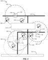
- FIG. 3 is a conceptual diagram of example drone routing within a delivery zone 220.
- the delivery zone 220 may include roads 310 that may be traversed by the land vehicle 120 to reach dispatch locations 130.
- the dispatch locations 130 may be located anywhere along the roads 310 (e.g., in a residential area).
- regulations may prevent land vehicles 120 from stopping along a highway 312 to dispatch UAVs 140.
- a highway 312 may, however, include designated parking areas that a land vehicle 120 may utilize as a dispatch location 130.
- the delivery zone 220 may include one or more restricted areas 314 that are areas designated as off limits to the flight path of UAVs 140, such as areas associated with an airport or a government building, or, in some cases, private property.
- the vehicle and drone management computer system 112 may maintain a database of restricted areas 314 within each geographic region 210.
- the vehicle and drone management computer system 112 may generate the database by applying rules to existing databases such as road databases and property records.
- the vehicle and drone management computer system 112 routes the land vehicle 120 by determining a set of dispatch locations 130 within the zone 220.
- the dispatch locations 130 are based on the destinations 230 and the drone range 320.
- Dispatch locations 130 are selected that maximize the number of destinations 230 within the drone range 320 from the dispatch locations 130.
- the dispatch locations 130 are selected by determining a dispatch area 322 for each destination 230, then selecting dispatch locations 130 where the most dispatch areas 322 overlap.
- a dispatch area 322 refers to an area surrounding a destination 230 from which a UAV 140 is dispatched to deliver a package to the destination 230.
- the dispatch area 322 is centered on the destination 230 and has a radius based on the range of the UAV 140.
- the UAV 140 may be dispatched from any dispatch location 130 within the dispatch area 322 and return to any dispatch location 130 or 132 within the dispatch area 322. Destinations 230 covered by a selected dispatch location 130 are removed from the set of destinations 230 to be covered and another dispatch location 130 selected based on the remaining destinations 230 until every destination 230 is covered by a respective dispatch location 130.
- the selection of dispatch locations 130 may also need to account for restricted areas 314. For example, although a given dispatch location 130 within the restricted area 314 may cover one or more destinations 230, less convenient dispatch locations 130 may be selected to avoid placing the dispatch location 130 (and/or the flight path of UAVs 140) within the restricted area 314.
- each UAV 140 may be autonomously piloted based on a route provided by the vehicle and drone management computer system 112 using autonomous navigation rules. Further, each UAV 140 may be provided with GPS data for a delivery destination 230, and, optionally, with a street address. Each UAV 140 may also be provided with the GPS location and/or physical street location of the dispatch point within the dispatch location 130, or determine the location of the dispatch point based on GPS measurements. The UAV 140 may calculate the route from the dispatch location 130 to the physical delivery address of the respective delivery destination 130 using the autonomous navigation rules. In an aspect, a preferred route is a direct path from the dispatch location 130 to the physical delivery address or other designated drop-off location of the respective delivery destination 130 to minimize time and energy (battery) usage.
- a default autonomous navigation rule may be to determine a straight path from the dispatch location 130 to the destination 230 at a specified height.
- the UAV 140 and/or the vehicle and drone management computer system 112 may completely or partially (e.g., both in combination) plan a route around known obstacles (trees, power lines, buildings, towers etc.) by using stored geometric information.
- the autonomous navigation rules may include a rule to avoid known obstacles by a configured distance (e.g., 10 feet).
- the UAV 140 may navigate around obstacles using the onboard camera system to locate objects and maintain a specified distance, which may be the same as the configured distance from known obstacles, or a different distance (e.g., 5 feet).
- the UAV 140 may perform object identification on obstacles using the on-camera system.
- the UAV 140 may recognize and categorize an obstruction and then make a decision as to the threshold distance and/or the most effective mitigation action.
- Local regulations may preclude the transit of the UAV 140 over private property, which may also be considered a type of restricted area 314, in which case the UAV 140 may use autonomous navigation rules to determine a route over public roadways, alleyways, and other public rights of way.
- the autonomous navigation rules may designate the restricted areas 314, and the UAV 140 may autonomously select a route that avoids the restricted areas 314.
- the UAV 140 may deliver the package.
- the respective destination 230 may be associated with specific delivery instructions.
- a customer may submit delivery instructions when placing an order.
- the delivery instructions may include specific GPS coordinates of a drop off location within a property to deliver the package or recognizable objects to orient the UAV 140.
- recognizable objects may include a landing pad, beacon, markings, building façade, door frame, or other feature having optically recognizable characteristics.
- the UAV 140 may use the onboard camera to identify the recognizable object, then orient itself with respect to the recognizable object.
- the UAV 140 may release the package at the destination 230.
- the UAV 140 may also document delivery of the package.
- the UAV 140 may record a video or photograph of the package at the destination 230.
- the UAV 140 may encounter difficulties that cannot be resolved autonomously. For example, the UAV 140 may encounter a barrier or the UAV 140 may become damaged.
- the UAV 140 may transmit its current location to the land vehicle 120 for the operator to assist the UAV 140. Because the land vehicle 120 is within the round trip distance of the UAV 140, the operator may be significantly closer to the UAV 140 than an operator at the warehouse 110. In some cases, the operator may retrieve a disabled drone and complete the delivery.
- FIG. 4 is a flowchart of a method 400 of delivering packages using the vehicle and drone management computer system 112.
- the vehicle and drone management computer system 112 may communicate with various components of the management system 100, for example via a wireless data connection, to provide instructions for controlling the component or providing input into an autonomous control process.
- the method 400 includes determining, based on a number of packages to be delivered to destinations in a geographical area, a number of land vehicles to carry the packages to within a round-trip range of each of the destinations.
- the allocation component 114 of the vehicle and drone management computer system 112 determines, based on a number of packages to be delivered to destinations 230 in the geographic region 210, the number of land vehicles 120 to carry the packages to within the UAV round-trip range of each of the destinations.
- the round-trip range may is based on a round trip range of at least one UAV 140 carried on each land vehicle 120.
- the number of land vehicles 120 may be based on the range and capacity of each land vehicle 120 and the round trip range of the UAVs 140.
- the block 410 may optionally include dividing the geographical area into a number of zones.
- the allocation component 114 of the vehicle and drone management computer system 112 may divide the geographic region 210 into a number of zones 220.
- Each zone 220 may have a substantially equal number, volume, or weight of packages.
- the method 400 includes allocating the number of packages to the number of land vehicles, each land vehicle being allocated a set of destinations.
- the allocation component 114 allocates the number of packages to the number of land vehicles 120, each land vehicle 120 being allocated a set of destinations 230 within a respective zone 220.
- the method 400 includes determining a route for each land vehicle that brings the land vehicle within the UAV round-trip range of each destination within the set of destinations.
- the routing component 116 determines a route for each land vehicle 120 that brings the land vehicle 120 within the UAV round-trip range of each destination 230 within the set of destinations.
- the block 430 includes determining a dispatch location 130 within the UAV round-trip range of each destination 230.
- the vehicle and drone management computer system 112 of the management system 100 determines the dispatch location 130 within the drone range 320 of each destination 230.
- the block 430 includes determining a minimum set of dispatch locations.
- the routing component 116 determines the minimum set of dispatch locations 130.
- the vehicle and drone management computer system 112 selects dispatch locations 130 that maximize the number of destinations 230 within the drone range 320.
- the block 430 may optionally include determining an optimal route between the dispatch locations.
- the routing component 116 of the vehicle and drone management computer system 112 may determine an optimal route between the dispatch locations 130.
- the optimal route may be a shortest or fastest route between the dispatch locations 130.
- the computer system 112 may determine the optimal route using the dispatch locations 130 as input into known routing algorithms for land vehicles 120.
- the method 400 includes dispatching, for each destination, a UAV carrying the package from the land vehicle at a dispatch location along the respective route.
- the dispatch component 118 dispatches, for each destination 230, the UAV 140 carrying the package from the land vehicle 120 at the dispatch location 130 along the respective route.
- the block 440 may optionally include providing the UAV with an aerial route from the dispatch location to the respective destination and then to a pickup location on the route.
- the pickup location may be, for example, the second dispatch location 132
- the dispatch component 118 may provide the UAV 140 with the aerial route from the dispatch location 130 to the respective destination 230.
- the dispatch component 118 may also provide an aerial route from the respective destination 230 to a pickup location, which may be the same as the dispatch location 130, or may be a second dispatch location 132.
- the UAV 140 may then autonomously navigate along the aerial route. If the UAV 140 diverges from the aerial route by a threshold amount, control of the UAV 140 may be passed to an operator at the land vehicle 120 or an operator at a more remote location, who may control the UAV 140 based on input from the GPS sensor and the on board camera.
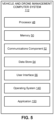
- FIG. 5 is a block diagram of an example of the vehicle and drone management computer system 112 in accordance with an implementation, including additional component details as compared to FIG. 1 .
- vehicle and drone management computer system 112 includes processor 48 for carrying out processing functions associated with one or more of components and functions described herein.
- Processor 48 can include a single or multiple set of processors or multi-core processors.
- processor 48 can be implemented as an integrated processing system and/or a distributed processing system.
- processor 48 may include a central processing unit (CPU).
- vehicle and drone management computer system 112 may include memory 50 for storing instructions executable by the processor 48 for carrying out the functions described herein.
- memory 50 may store instructions for executing one or more of the allocation component 114, routing component 116, or dispatch component 118.
- vehicle and drone management computer system 112 may include a communications component 52 that provides for establishing and maintaining communications with one or more parties, vehicles, or drones, utilizing hardware, software, and services as described herein.
- Communications component 52 may carry communications between components on vehicle and drone management computer system 112, as well as between vehicle and drone management computer system 112 and external devices, such as devices located across a communications network and/or devices serially or locally connected to vehicle and drone management computer system 112.
- communications component 52 may include one or more buses, and may further include transmit chain components and receive chain components associated with a transmitter and receiver, respectively, operable for interfacing with external devices.
- vehicle and drone management computer system 112 may include a data store 54, which can be any suitable combination of hardware and/or software, that provides for mass storage of information, databases, and programs employed in connection with implementations described herein.
- data store 54 may be a data repository for operating system 140 and/or applications 150.
- Vehicle and drone management computer system 112 may also include a user interface component 56 operable to receive inputs from a user of computer device 102 and further operable to generate outputs for presentation to the user.
- User interface component 56 may include one or more input devices, including but not limited to a keyboard, a number pad, a mouse, a touch-sensitive display, a navigation key, a function key, a microphone, a voice recognition component, any other mechanism capable of receiving an input from a user, or any combination thereof.
- user interface component 56 may include one or more output devices, including but not limited to a display, a speaker, a haptic feedback mechanism, a printer, any other mechanism capable of presenting an output to a user, or any combination thereof.
- user interface component 56 may transmit and/or receive messages corresponding to the operation of operating system 140 and/or application 150.
- processor 48 executes operating system 140 and/or application 150, and memory 50 or data store 54 may store them.
- a component may be, but is not limited to being, a process running on a processor, a processor, an object, an executable, a thread of execution, a program, and/or a computer.
- an application running on a computer device and the computer device can be a component.
- One or more components can reside within a process and/or thread of execution and a component may be localized on one computer and/or distributed between two or more computers.
- these components can execute from various computer readable media having various data structures stored thereon.
- the components may communicate by way of local and/or remote processes such as in accordance with a signal having one or more data packets, such as data from one component interacting with another component in a local system, distributed system, and/or across a network such as the Internet with other systems by way of the signal.
- a signal having one or more data packets, such as data from one component interacting with another component in a local system, distributed system, and/or across a network such as the Internet with other systems by way of the signal.
- the term "or” is intended to mean an inclusive “or” rather than an exclusive “or.” That is, unless specified otherwise, or clear from the context, the phrase “X employs A or B” is intended to mean any of the natural inclusive permutations. That is, the phrase “X employs A or B” is satisfied by any of the following instances: X employs A; X employs B; or X employs both A and B.
- the articles “a” and “an” as used in this application and the appended claims should generally be construed to mean “one or more” unless specified otherwise or clear from the context to be directed to a singular form.
- DSP digital signal processor
- ASIC application specific integrated circuit
- FPGA field programmable gate array
- a general-purpose processor may be a microprocessor, but, in the alternative, the processor may be any conventional processor, controller, microcontroller, or state machine.
- a processor may also be implemented as a combination of computer devices, e.g., a combination of a DSP and a microprocessor, a plurality of microprocessors, one or more microprocessors in conjunction with a DSP core, or any other such configuration. Additionally, at least one processor may comprise one or more components operable to perform one or more of the steps and/or actions described above.
- a software module may reside in RAM memory, flash memory, ROM memory, EPROM memory, EEPROM memory, registers, a hard disk, a removable disk, a CD-ROM, or any other form of storage medium known in the art.
- An exemplary storage medium may be coupled to the processor, such that the processor can read information from, and write information to, the storage medium.
- the storage medium may be integral to the processor.
- the processor and the storage medium may reside in an ASIC. Additionally, the ASIC may reside in a user terminal.
- processor and the storage medium may reside as discrete components in a user terminal. Additionally, in some implementations, the steps and/or actions of a method or algorithm may reside as one or any combination or set of codes and/or instructions on a machine readable medium and/or computer readable medium, which may be incorporated into a computer program product.
- the functions described may be implemented in hardware, software, firmware, or any combination thereof. If implemented in software, the functions may be stored or transmitted as one or more instructions or code on a computer-readable medium.
- Computer-readable media includes both computer storage media and communication media including any medium that facilitates transfer of a computer program from one place to another.
- a storage medium may be any available media that can be accessed by a computer.
- such computer-readable media can comprise RAM, ROM, EEPROM, CD-ROM or other optical disk storage, magnetic disk storage or other magnetic storage devices, or any other medium that can be used to carry or store desired program code in the form of instructions or data structures and that can be accessed by a computer.
- Disk and disc includes compact disc (CD), laser disc, optical disc, digital versatile disc (DVD), floppy disk and Blu-ray disc where disks usually reproduce data magnetically, while discs usually reproduce data optically with lasers. Combinations of the above should also be included within the scope of computer-readable media.
Landscapes
- Engineering & Computer Science (AREA)
- Physics & Mathematics (AREA)
- General Physics & Mathematics (AREA)
- Remote Sensing (AREA)
- Radar, Positioning & Navigation (AREA)
- Aviation & Aerospace Engineering (AREA)
- Automation & Control Theory (AREA)
- Business, Economics & Management (AREA)
- Economics (AREA)
- Development Economics (AREA)
- Entrepreneurship & Innovation (AREA)
- Human Resources & Organizations (AREA)
- Marketing (AREA)
- Operations Research (AREA)
- Quality & Reliability (AREA)
- Strategic Management (AREA)
- Tourism & Hospitality (AREA)
- General Business, Economics & Management (AREA)
- Theoretical Computer Science (AREA)
- Transportation (AREA)
- Mechanical Engineering (AREA)
- Traffic Control Systems (AREA)
Description
- The present disclosure generally relates to a system for managing vehicles, including managing the interaction of manned vehicles and unmanned drones.
- Conventionally, systems may manage the operation of a fleet of vehicles. For example, systems may manage vehicles that deliver packages or cargo. One inefficiency in such systems is that the last leg of a delivery operation (e.g., from a sorting facility to a destination address) has been performed by a delivery person who both drives a delivery vehicle and manually carries the package from the delivery vehicle to the destination address.
- Various drone delivery systems have been proposed where an unmanned aerial vehicle (UAV) carries a package from the sorting facility to the destination address. Such systems, however, are limited to the round-trip range of the UAV and would require a large number of sorting facilities in order to cover a geographic area.
- In view of the above, it can be appreciated that there are problems, shortcomings or disadvantages associated with drone delivery systems, and that it would be desirable if improved systems and methods for delivering packages using UAVs were available.
US Patent Publication No. US2016/244187 A1 discloses a system in which unmanned aerial vehicles (UAVs) may be used to transport packages between different entities. A UAV landing perch is disclosed. The perch may be operable to assist a UAV during takeoffs or during landings, provide charge to the UAV, enable communications with the UAV, and/or provide storage to the UAV when the UAV is not in use. A road vehicle may host a plurality of landing perches. - The invention is defined in
independent method claim 1 and independent system claim 10. Optional features of the invention are recited in dependent claims. These and other aspects of the invention will become more fully understood upon a review of the detailed description, which follows. -
-
FIG. 1 is a conceptual diagram of an example vehicle and drone management system. -
FIG. 2 is a conceptual diagram of example delivery zones. -
FIG. 3 is a conceptual diagram of example drone routing. -
FIG. 4 is a flowchart of an example method of delivering packages using a management system. -
FIG. 5 is a block diagram of an example of the vehicle and drone management computer system. - The detailed description set forth below in connection with the appended drawings is intended as a description of various configurations and is not intended to represent the only configurations in which the concepts described herein may be practiced. The detailed description includes specific details for the purpose of providing a thorough understanding of various concepts. However, it will be apparent to those skilled in the art that these concepts may be practiced without these specific details. In some instances, well known components are shown in block diagram form in order to avoid obscuring such concepts.
- Unmanned aerial vehicles (UAVs) or drones offer many opportunities in the logistics and shipping fields. UAVs may provide fast delivery times by bypassing fixed road routes and traffic congestion. UAVs may also perform the last leg of delivery, placing the package at the address, which is typically performed by a human.
- UAVs, however, also present difficulties in comparison to the management of vehicles using traditional delivery methods. Management systems have to consider cargo capacity and delivery range, which are factors that limit the ability of UAVs to deliver packages. The amount of fixed infrastructure to support full UAV delivery over a large geographic area may be expensive. Additionally, autonomous UAVs are likely to experience unpredictable events and malfunctions that require human involvement.
- The present disclosure provides for a hybrid vehicle and drone management system in which land vehicles transport packages from a warehouse to dispatch locations and delivery UAVs perform a last leg of delivery to the delivery addresses. The hybrid system increases capacity by utilizing the higher cargo capacity of the land vehicles for a majority of the delivery distance while utilizing one or more UAVs for rapid delivery to final destinations.
- The present disclosure further provides for a routing system that allocates packages to the land vehicles, plans routes for the land vehicles and UAVs, and dispatches the UAVs to the delivery locations.
- Turning now to the Figures,
FIG. 1 illustrates an example vehicle anddrone management system 100. Themanagement system 100 includes awarehouse 110,land vehicles 120, andUAVs 140. Themanagement system 100 routes one ormore land vehicles 120 from thewarehouse 110 to one or morefirst dispatch locations 130. At the respectivefirst dispatch locations 130, the UAVs 140 are dispatched from theland vehicles 120 to deliver packages to one or morefinal destinations 142. In some cases, the UAVs 140 may then return to theland vehicles 120 at a pickup location and are driven to other dispatch locations for delivery of one or more additional packages to one or more additionalfinal destinations 144. In an aspect, the pickup location may be the same as thedispatch location land vehicles 120 move from a respectivefirst dispatch location 130 to asecond dispatch location 132. In some cases, one ormore UAVs 140 may be dispatched from thefirst dispatch location 130, but return to theland vehicle 120 at the second dispatch location 132 (which may be considered a pickup location), depending on a routing plan for a particular delivery zone. - The
warehouse 110 may be a central facility for a geographic region. In an aspect, for example, thewarehouse 110 may include an inventory for one or more retailers. As products are ordered, themanagement system 100 may control one or more parts of the process of pulling the products from the inventory, packaging the products, and allocating the packages for delivery, which is controlled by themanagement system 100. In another aspect, thewarehouse 110 may be a shipping or sorting facility. Thewarehouse 110 may receive packages (e.g., via long-haul trucking, air cargo, ship, or rail) and allocate the received packages for delivery. Themanagement system 100 may allocate packages for delivery on a periodic, volume, and/or demand basis. For example, themanagement system 100 may allocate packages for a daily delivery, but may also allocate packages for supplemental deliveries as volume or demand requires. - A specially-configured vehicle and drone
management computer system 112 for management of vehicles and drones, which may be located in thewarehouse 110 or in a remote location connected to thewarehouse 110 via a wired orwireless communication link 146, may be configured to perform various operations described herein. The vehicle and dronemanagement computer system 112 includes anallocation component 114 for determining, based on a number of packages to be delivered tofinal destinations 142 and/or 144 in a geographical area, a number ofland vehicles 120 to carry the packages and allocating the packages to theland vehicles 120. Thecomputer system 112 includes arouting component 116 for determining a route for eachland vehicle 120 that brings theland vehicle 120 within the distance of eachfinal destination dispatch component 118 for dispatching, for eachfinal destination land vehicle 120. In an aspect, the vehicle and dronemanagement computer system 112 may include a computer-readable medium storing computer executable code for implementing each of theallocation component 114,routing component 116, anddispatch component 118. In another aspect, the vehicle and dronemanagement computer system 112 may be implemented as a virtual server in a cloud system where computing resources are allocated as necessary. One or more instances of theallocation component 114,routing component 116, ordispatch component 118 may be implemented as a non-transitory computer executable code for execution by one or more processors of the cloud system. - The
land vehicles 120 may be vehicles that transport packages andUAVs 140 over a road network. In an aspect, for example, theland vehicles 120 may be commercial delivery vehicles equipped for dispatching drones. For example, in addition to a traditional cargo bay, theland vehicles 120 may each include a UAV bay for storing one ormore UAVs 140. TheUAVs 140 may autonomously return to the UAV bay after completing a delivery. Theland vehicles 120 may also include UAV support equipment, such as fuel, fuel cells, replacement batteries, or battery chargers for refreshing power on theUAVs 140 to increase or maintain the delivery range of theUAVs 140. - The
land vehicles 120 are autonomous vehicles. In an aspect, the land vehicles may be semi-autonomous vehicles. Theland vehicles 120 receive a planned route from therouting component 116 of the vehicle and dronemanagement computer system 112. Theland vehicles 120 autonomously navigate from thewarehouse 110 to eachdispatch location 130 and/or 132 according to the planned route. An operator may serve as a backup driver while theland vehicle 120 navigates autonomously. The operator may perform additional loading, dispatch, retrieval, and maintenance operations on theUAVs 140 when at thedispatch location 130. - The
dispatch location 130 and/or 132 may be a specific location or a location within a geographic area whereUAVs 140 may be moved vialand vehicles 120 to initiate package delivery to one or morefinal destinations 142 and/or 144 within a range of theUAVs 140 at thedispatch location 130 and/or 132. The dispatching ofUAVs 140 may be regulated by federal, state, or local rules. The ability to dispatchUAVs 140 may also be impacted by practical concerns not specifically regulated. For example, theland vehicle 120 may need to park, stand, or have a limited amount of movement for a threshold amount of time at thedispatch location 130 and/or 132 in order for eachUAV 140 to deliver its package and return to theland vehicle 120. The vehicle and dronemanagement computer system 112 may be configured with a database ofpotential dispatch locations 130 and/or 132 within a delivery zone. Thedispatch locations 130 and/or 132 for a particular planned route are selected when planning the route based on the allocated packages. Theland vehicle 120 may also dynamically select or modifydispatch locations 130 and/or 132 based on current conditions at a time of arrival. For example, if a designated parking area at adispatch location 130 and/or 132 is occupied, the vehicle and dronemanagement computer system 112 and/or theland vehicle 120 may select anearby dispatch location 130 and/or 132 not included in the route. Two or morenearby dispatch locations 130 and/or 132 may be selected to cover all delivery destinations. - The
UAVs 140 may include any UAV capable of delivering packages to adestination 142 and/or 144. In an aspect, theUAVs 140 are aircraft, such as but not limited to electrically powered, multi-rotor helicopters. Other UAVs may be powered by internal combustion engines.UAVs 140 may also include fixed-wing, tiltrotor, or lighter-than-air aircraft. TheUAVs 140 may be equipped with a camera, a satellite-based and/or terrestrial-based location system (e.g., global positioning system (GPS)), and a wireless communication device (e.g., a cellular and/or Wi-Fi modem). EachUAV 140 may carry one or more packages having a total weight up to a maximum load for theUAV 140. Further, eachUAV 140 may be equipped with releasable package rack for retaining the package during flight and releasing the package at thedestination 142 and/or 144. - Each
UAV 140 may have a maximum range, e.g., a maximum distance that it can fly on a given battery charge. The maximum range of eachUAV 140 may be dependent on multiple variables including the battery capacity, charge level of the batteries, altitude, temperature, wind, and the size, aerodynamic properties, and weight of the payload (e.g., one or more packages). The maximum range may be determined for each model ofUAV 140 utilized by themanagement system 100. The vehicle and dronemanagement computer system 112 may repeatedly estimate a current range for a givenUAV 140 based on observed measurements of the above variables. The vehicle and dronemanagement computer system 112 can calculate a round trip distance for eachUAV 140 based on the current range, but also taking into account a safety margin. The safety margin may be an additional estimated distance to allow unexpected events (e.g., delays, obstructions, or weather), and to promote safe operations, so that theUAV 140 could be assured a safe return to thedispatch location 130 and/or 132 and/or to theland vehicle 120. -
FIG. 2 is a conceptual diagram 200 ofexample delivery zones 220 within ageographic region 210. The vehicle and dronemanagement computer system 112 may manage deliveries within thegeographic region 210. Thegeographic region 210 may be any geographic area corresponding to arespective warehouse 110 that can receive and support delivery of one or more packages having afinal destination 230 within thegeographic region 210. It should be noted thatfinal destination 230 inFig. 2 may correspond tofinal destinations 142 and/or 144 ofFig. 1 . For example, thewarehouse 110 may be responsible for a city, county, or small state, or an arbitrary area having a number of potential customers. The vehicle and dronemanagement computer system 112 may determine a givendelivery destination 230 for each package, for example, by reading a label attached to the package. The vehicle and dronemanagement computer system 112 may allocate the packages or associateddestinations 230 todelivery zones 220 based on the geographic coordinates of thedestinations 230. Thedestinations 230 may be grouped together. The size of the groups may depend on the cargo capacity of eachland vehicle 120. As illustrated, for example, thedestinations 230 may be clustered into groups of 10. It should be appreciated that the vehicle and dronemanagement computer system 112 may use larger or smaller groups, and the number of packages in a group may be based on package volume, and/or package weight, and/or a geographic area and/or specific distances covered by eachgeographic region 210 or between the group ofdestinations 230, instead of or in addition to the number of packages ordestinations 230. - In an implementation, the vehicle and drone
management computer system 112 may receive or allocate a large number ("n") packages, i.e. n>>1, that are to be delivered to some number of destinations ("y"). The number of destinations, y, may also include pick up locations. For example, vehicle and dronemanagement computer system 112 may receive requests to pick up a package at a location. For planning purposes, a pick-up location and the associated package may be treated in a similar manner as a delivery because the costs are similar. In an aspect, a pick-up operation may simply be the inverse of a delivery operation in which the package is transported from the destination, but the round-trip distance for theUAV 140 remains the same. The vehicle and dronemanagement computer system 112 may group multiplefinal destinations 230 into geocentrically-arrangeddelivery zones 220. The vehicle and dronemanagement computer system 112 assigns a dispatch area to eachfinal destination 230 based on the maximum range of theUAV 140, which may be a round trip range. Assuming that some of the packages may be delivered to the same destination, the number of packages to be delivered will be greater than or equal to the number of destinations; i.e. "n ≥ y". - The
land vehicles 120 are capable of carrying one ormore UAVs 140. The vehicle and dronemanagement computer system 112 may determine the number, "v," ofland vehicles 120 for delivering the n packages based on number of packages, cargo capacity of the vehicles, and the distances from the destinations, y. Other factors that may affect the number of vehicles include the size, weight, priority, timing requirements, and handling instructions for each package. The number of vehicles "v" used to deliver theUAVs 140 to thefinal destinations 230 will likely be less than or equal to the number offinal destinations 230, "v ≤ y" because eachland vehicle 120 will be able to carry one ormore UAVs 140 and eachUAV 140 will be able to make one or more deliveries of packages to the various locations, "y". - Thus, in the illustrated example of
Fig. 2 , the vehicle and dronemanagement computer system 112 may associate asingle warehouse 110 to supportmultiple delivery zones 220 within thegeographic region 210. Further, as will be explained in more detail inFig. 3 , the vehicle and dronemanagement computer system 112 may allocate one or more land vehicles 120 (not shown) to each of themultiple delivery zones 220, allocates corresponding packages to eachland vehicle 120, and control one ormore UAVs 140 on eachland vehicle 120 to deliver the packages to the correspondingfinal destinations 230 within therespective delivery zone 220. -
FIG. 3 is a conceptual diagram of example drone routing within adelivery zone 220. Thedelivery zone 220 may includeroads 310 that may be traversed by theland vehicle 120 to reachdispatch locations 130. In an aspect, thedispatch locations 130 may be located anywhere along the roads 310 (e.g., in a residential area). In contrast, regulations may preventland vehicles 120 from stopping along ahighway 312 to dispatchUAVs 140. Ahighway 312 may, however, include designated parking areas that aland vehicle 120 may utilize as adispatch location 130. Also, thedelivery zone 220 may include one or morerestricted areas 314 that are areas designated as off limits to the flight path ofUAVs 140, such as areas associated with an airport or a government building, or, in some cases, private property. Accordingly, neitherdispatch locations 130 nor UAV routes may be located in the restrictedarea 314. The vehicle and dronemanagement computer system 112 may maintain a database of restrictedareas 314 within eachgeographic region 210. For example, in one implementation, the vehicle and dronemanagement computer system 112 may generate the database by applying rules to existing databases such as road databases and property records. - The vehicle and drone
management computer system 112 routes theland vehicle 120 by determining a set ofdispatch locations 130 within thezone 220. Thedispatch locations 130 are based on thedestinations 230 and thedrone range 320.Dispatch locations 130 are selected that maximize the number ofdestinations 230 within thedrone range 320 from thedispatch locations 130. Thedispatch locations 130 are selected by determining adispatch area 322 for eachdestination 230, then selectingdispatch locations 130 where themost dispatch areas 322 overlap. Adispatch area 322 refers to an area surrounding adestination 230 from which aUAV 140 is dispatched to deliver a package to thedestination 230. Thedispatch area 322 is centered on thedestination 230 and has a radius based on the range of theUAV 140. Accordingly, theUAV 140 may be dispatched from anydispatch location 130 within thedispatch area 322 and return to anydispatch location dispatch area 322.Destinations 230 covered by a selecteddispatch location 130 are removed from the set ofdestinations 230 to be covered and anotherdispatch location 130 selected based on the remainingdestinations 230 until everydestination 230 is covered by arespective dispatch location 130. The selection ofdispatch locations 130 may also need to account forrestricted areas 314. For example, although a givendispatch location 130 within the restrictedarea 314 may cover one ormore destinations 230, lessconvenient dispatch locations 130 may be selected to avoid placing the dispatch location 130 (and/or the flight path of UAVs 140) within the restrictedarea 314. - In an aspect, each
UAV 140 may be autonomously piloted based on a route provided by the vehicle and dronemanagement computer system 112 using autonomous navigation rules. Further, eachUAV 140 may be provided with GPS data for adelivery destination 230, and, optionally, with a street address. EachUAV 140 may also be provided with the GPS location and/or physical street location of the dispatch point within thedispatch location 130, or determine the location of the dispatch point based on GPS measurements. TheUAV 140 may
calculate the route from thedispatch location 130 to the physical delivery address of therespective delivery destination 130 using the autonomous navigation rules. In an aspect, a preferred route is a direct path from thedispatch location 130 to the physical delivery address or other designated drop-off location of therespective delivery destination 130 to minimize time and energy (battery) usage. For example, a default autonomous navigation rule may be to determine a straight path from thedispatch location 130 to thedestination 230 at a specified height. TheUAV 140 and/or the vehicle and dronemanagement computer system 112 may completely or partially (e.g., both in combination) plan a route around known obstacles (trees, power lines, buildings, towers etc.) by using stored geometric information. For example, the autonomous navigation rules may include a rule to avoid known obstacles by a configured distance (e.g., 10 feet). Additionally, theUAV 140 may navigate around obstacles using the onboard camera system to locate objects and maintain a specified distance, which may be the same as the configured distance from known obstacles, or a different distance (e.g., 5 feet). In an aspect, theUAV 140 may perform object identification on obstacles using the on-camera system. TheUAV 140 may recognize and categorize an obstruction and then make a decision as to the threshold distance and/or the most effective mitigation action. Local regulations may preclude the transit of theUAV 140 over private property, which may also be considered a type of restrictedarea 314, in which case theUAV 140 may use autonomous navigation rules to determine a route over public roadways, alleyways, and other public rights of way. For example, the autonomous navigation rules may designate the restrictedareas 314, and theUAV 140 may autonomously select a route that avoids the restrictedareas 314. - When the
UAV 140 reaches arespective destination 230, theUAV 140 may deliver the package. In an aspect, therespective destination 230 may be associated with specific delivery instructions. For example, a customer may submit delivery instructions when placing an order. The delivery instructions may include specific GPS coordinates of a drop off location within a property to deliver the package or recognizable objects to orient theUAV 140. For example, recognizable objects may include a landing pad, beacon, markings, building façade, door frame, or other feature having optically recognizable characteristics. TheUAV 140 may use the onboard camera to identify the recognizable object, then orient itself with respect to the recognizable object. TheUAV 140 may release the package at thedestination 230. TheUAV 140 may also document delivery of the package. For example, theUAV 140 may record a video or photograph of the package at thedestination 230. - In an aspect, the
UAV 140 may encounter difficulties that cannot be resolved autonomously. For example, theUAV 140 may encounter a barrier or theUAV 140 may become damaged. TheUAV 140 may transmit its current location to theland vehicle 120 for the operator to assist theUAV 140. Because theland vehicle 120 is within the round trip distance of theUAV 140, the operator may be significantly closer to theUAV 140 than an operator at thewarehouse 110. In some cases, the operator may retrieve a disabled drone and complete the delivery. -
FIG. 4 is a flowchart of amethod 400 of delivering packages using the vehicle and dronemanagement computer system 112. The vehicle and dronemanagement computer system 112 may communicate with various components of themanagement system 100, for example via a wireless data connection, to provide instructions for controlling the component or providing input into an autonomous control process. - In
block 410, themethod 400 includes determining, based on a number of packages to be delivered to destinations in a geographical area, a number of land vehicles to carry the packages to within a round-trip range of each of the destinations. Theallocation component 114 of the vehicle and dronemanagement computer system 112 determines, based on a number of packages to be delivered todestinations 230 in thegeographic region 210, the number ofland vehicles 120 to carry the packages to within the UAV round-trip range of each of the destinations. The round-trip range may is based on a round trip range of at least oneUAV 140 carried on eachland vehicle 120. The number ofland vehicles 120 may be based on the range and capacity of eachland vehicle 120 and the round trip range of theUAVs 140. Insub-block 412, theblock 410 may optionally include dividing the geographical area into a number of zones. For example, theallocation component 114 of the vehicle and dronemanagement computer system 112 may divide thegeographic region 210 into a number ofzones 220. Eachzone 220 may have a substantially equal number, volume, or weight of packages. - In
block 420, themethod 400 includes allocating the number of packages to the number of land vehicles, each land vehicle being allocated a set of destinations. Theallocation component 114 allocates
the number of packages to the number of
land vehicles 120, eachland vehicle 120 being allocated a set ofdestinations 230 within arespective zone 220. - In
block 430, themethod 400 includes determining a route for each land vehicle that brings the land vehicle within the UAV round-trip range of each destination within the set of destinations. Therouting component 116 determines a route for eachland vehicle 120 that brings theland vehicle 120 within the UAV round-trip range of eachdestination 230 within the set of destinations. Insub-block 432, theblock 430 includes determining adispatch location 130 within the UAV round-trip range of eachdestination 230. The vehicle and dronemanagement computer system 112 of themanagement system 100 determines thedispatch location 130 within thedrone range 320 of eachdestination 230. Insub-block 434, theblock 430 includes determining a minimum set of dispatch locations. Therouting component 116 determines the minimum set ofdispatch locations 130. The vehicle and dronemanagement computer system 112 selectsdispatch locations 130 that maximize the number ofdestinations 230 within thedrone range 320. Insub-block 436, theblock 430 may optionally include determining an optimal route between the dispatch locations. In an aspect, for example, therouting component 116 of the vehicle and dronemanagement computer system 112 may determine an optimal route between thedispatch locations 130. The optimal route may be a shortest or fastest route between thedispatch locations 130. For example, thecomputer system 112 may determine the optimal route using thedispatch locations 130 as input into known routing algorithms forland vehicles 120. - In
block 440, themethod 400 includes dispatching, for each destination, a UAV carrying the package from the land vehicle at a dispatch location along the respective route. Thedispatch component 118 dispatches, for eachdestination 230, theUAV 140 carrying the package from theland vehicle 120 at thedispatch location 130 along the respective route. Insub-block 442, theblock 440 may optionally include providing the UAV with an aerial route from the dispatch location to the respective destination and then to a pickup location on the route. The pickup location may be, for example, thesecond dispatch location 132 In an aspect, for example, thedispatch component 118 may provide theUAV 140 with the aerial route from thedispatch location 130 to therespective destination 230. Thedispatch component 118 may also provide an aerial route from therespective destination 230 to a pickup location, which may be the same as thedispatch location 130, or may be asecond dispatch location 132. TheUAV 140 may then autonomously navigate along the aerial route. If theUAV 140 diverges from the aerial route by a threshold amount, control of theUAV 140 may be passed to an operator at theland vehicle 120 or an operator at a more remote location, who may control theUAV 140 based on input from the GPS sensor and the on board camera. -
FIG. 5 is a block diagram of an example of the vehicle and dronemanagement computer system 112 in accordance with an implementation, including additional component details as compared toFIG. 1 . In one example, vehicle and dronemanagement computer system 112 includesprocessor 48 for carrying out processing functions associated with one or more of components and functions described herein.Processor 48 can include a single or multiple set of processors or multi-core processors. Moreover,processor 48 can be implemented as an integrated processing system and/or a distributed processing system. In an implementation, for example,processor 48 may include a central processing unit (CPU). In an example, vehicle and dronemanagement computer system 112 may includememory 50 for storing instructions executable by theprocessor 48 for carrying out the functions described herein. In an implementation, for example,memory 50 may store instructions for executing one or more of theallocation component 114,routing component 116, ordispatch component 118. - Further, vehicle and drone
management computer system 112 may include acommunications component 52 that provides for establishing and maintaining communications with one or more parties, vehicles, or drones, utilizing hardware, software, and services as described herein.Communications component 52 may carry communications between components on vehicle and dronemanagement computer system 112, as well as between vehicle and dronemanagement computer system 112 and external devices, such as devices located across a communications network and/or devices serially or locally connected to vehicle and dronemanagement computer system 112. For example,communications component 52 may include one or more buses, and may further include transmit chain components and receive chain components associated with a transmitter and receiver, respectively, operable for interfacing with external devices. - Additionally, vehicle and drone
management computer system 112 may include adata store 54, which can be any suitable combination of hardware and/or software, that provides for mass storage of information, databases, and programs employed in connection with implementations described herein. For example,data store 54 may be a data repository foroperating system 140 and/orapplications 150. - Vehicle and drone
management computer system 112 may also include a user interface component 56 operable to receive inputs from a user of computer device 102 and further operable to generate outputs for presentation to the user. User interface component 56 may include one or more input devices, including but not limited to a keyboard, a number pad, a mouse, a touch-sensitive display, a navigation key, a function key, a microphone, a voice recognition component, any other mechanism capable of receiving an input from a user, or any combination thereof. Further, user interface component 56 may include one or more output devices, including but not limited to a display, a speaker, a haptic feedback mechanism, a printer, any other mechanism capable of presenting an output to a user, or any combination thereof. - In an implementation, user interface component 56 may transmit and/or receive messages corresponding to the operation of
operating system 140 and/orapplication 150. In addition,processor 48 executesoperating system 140 and/orapplication 150, andmemory 50 ordata store 54 may store them. - As used in this application, the terms "component," "system" and the like are intended to include a computer-related entity, such as but not limited to hardware, firmware, a combination of hardware and software, software, or software in execution. For example, a component may be, but is not limited to being, a process running on a processor, a processor, an object, an executable, a thread of execution, a program, and/or a computer. By way of illustration, both an application running on a computer device and the computer device can be a component. One or more components can reside within a process and/or thread of execution and a component may be localized on one computer and/or distributed between two or more computers. In addition, these components can execute from various computer readable media having various data structures stored thereon. The components may communicate by way of local and/or remote processes such as in accordance with a signal having one or more data packets, such as data from one component interacting with another component in a local system, distributed system, and/or across a network such as the Internet with other systems by way of the signal.
- Moreover, the term "or" is intended to mean an inclusive "or" rather than an exclusive "or." That is, unless specified otherwise, or clear from the context, the phrase "X employs A or B" is intended to mean any of the natural inclusive permutations. That is, the phrase "X employs A or B" is satisfied by any of the following instances: X employs A; X employs B; or X employs both A and B. In addition, the articles "a" and "an" as used in this application and the appended claims should generally be construed to mean "one or more" unless specified otherwise or clear from the context to be directed to a singular form.
- Various implementations or features may have been presented in terms of systems that may include a number of devices, components, modules, and the like. It is to be understood and appreciated that the various systems may include additional devices, components, modules, etc. and/or may not include all of the devices, components, modules etc. discussed in connection with the figures. A combination of these approaches may also be used.
- The various illustrative logics, logical blocks, and actions of methods described in connection with the embodiments disclosed herein may be implemented or performed with a specially-programmed one of a general purpose processor, a digital signal processor (DSP), an application specific integrated circuit (ASIC), a field programmable gate array (FPGA) or other programmable logic device, discrete gate or transistor logic, discrete hardware components, or any combination thereof designed to perform the functions described herein. A general-purpose processor may be a microprocessor, but, in the alternative, the processor may be any conventional processor, controller, microcontroller, or state machine. A processor may also be implemented as a combination of computer devices, e.g., a combination of a DSP and a microprocessor, a plurality of microprocessors, one or more microprocessors in conjunction with a DSP core, or any other such configuration. Additionally, at least one processor may comprise one or more components operable to perform one or more of the steps and/or actions described above.
- Further, the steps and/or actions of a method or algorithm described in connection with the implementations disclosed herein may be embodied directly in hardware, in a software module executed by a processor, or in a combination of the two. A software module may reside in RAM memory, flash memory, ROM memory, EPROM memory, EEPROM memory, registers, a hard disk, a removable disk, a CD-ROM, or any other form of storage medium known in the art. An exemplary storage medium may be coupled to the processor, such that the processor can read information from, and write information to, the storage medium. In the alternative, the storage medium may be integral to the processor. Further, in some implementations, the processor and the storage medium may reside in an ASIC. Additionally, the ASIC may reside in a user terminal. In the alternative, the processor and the storage medium may reside as discrete components in a user terminal. Additionally, in some implementations, the steps and/or actions of a method or algorithm may reside as one or any combination or set of codes and/or instructions on a machine readable medium and/or computer readable medium, which may be incorporated into a computer program product.
- In one or more implementations, the functions described may be implemented in hardware, software, firmware, or any combination thereof. If implemented in software, the functions may be stored or transmitted as one or more instructions or code on a computer-readable medium. Computer-readable media includes both computer storage media and communication media including any medium that facilitates transfer of a computer program from one place to another. A storage medium may be any available media that can be accessed by a computer. By way of example, and not limitation, such computer-readable media can comprise RAM, ROM, EEPROM, CD-ROM or other optical disk storage, magnetic disk storage or other magnetic storage devices, or any other medium that can be used to carry or store desired program code in the form of instructions or data structures and that can be accessed by a computer. Disk and disc, as used herein, includes compact disc (CD), laser disc, optical disc, digital versatile disc (DVD), floppy disk and Blu-ray disc where disks usually reproduce data magnetically, while discs usually reproduce data optically with lasers. Combinations of the above should also be included within the scope of computer-readable media.
Claims (12)
- A method (400) of delivering packages, comprising:determining, based on a number of packages to be delivered to destinations (230) in a geographical area, by a computer system (112) a number of autonomous land vehicles (120) to carry the packages to within an unmanned aerial vehicle (UAV) round-trip range of each of the destinations (230), wherein each land vehicle (120) carries at least one UAV (140) capable of delivering at least one of the number of packages to one of the destinations (230) within the UAV round-trip range;allocating by the computer system (112) the number of packages to the number of land vehicles (120), each land vehicle (120) being allocated a set of destinations (230);determining by the computer system (112) a route for each land vehicle (120) that brings the land vehicle (120) within the UAV round-trip range of each destination (230) within the set of destinations, wherein determining the route for each land vehicle (120) comprises:wherein the method further comprises:determining a dispatch area (322) for each destination (230), wherein the dispatch area (322) is centered on the destination (230) and has a radius based on the UAV (140) round-trip range;selecting a dispatch location (130, 132) at a location where the most dispatch areas (322) overlap;removing destinations (230) covered by the selected dispatch location (130, 132) from the set of destinations; andselecting another dispatch location (130, 132) until every destination (230) is covered by a respective dispatch location (130, 132), wherein each of the selected dispatch locations (130, 132) allows parking of the land vehicle (120);routing each land vehicle (120) to a first dispatch location (130);moving each land vehicle (120) from the first dispatch location (130) to a second dispatch location (132), wherein the first and the second dispatch locations (130, 132) are chosen from the selected dispatch locations (130, 132); anddispatching, for each destination (230), the at least one UAV (140) carrying a package from the respective land vehicle (120) at the selected dispatch locations (130, 132) along the route determined for each land vehicle (120).
- The method of claim 1, wherein the dispatching comprises providing the UAV (140) with an aerial route from the first dispatch location (130) to the respective destination (230) and then to a pickup location (130; 132) on the route.
- The method of claim 2, wherein the first dispatch location (130) and the pickup location (130) are the same.
- The method of claim 2, wherein the aerial route comprises geographic coordinates of the first dispatch location (130), the respective destination (230), and the pickup location and autonomous navigation rules.
- The method of claim 4, wherein the autonomous navigation rules include indications of restricted areas proximate the respective destination (230).
- The method of claim 1, wherein determining the number of land vehicles (120) is based on the range and capacity of each land vehicle (120) and the UAV round-trip range.
- The method of claim 6, wherein the UAV round-trip range is based on one or more of battery capacity, battery charge level, altitude, temperature, wind speed, package weight, and safety margin.
- The method of claim 1, wherein determining the number of land vehicles (120) comprises dividing the geographical area into a number of zones.
- The method of claim 1, wherein determining the route for each land vehicle (120) comprises selecting a route between the selected dispatch locations (130, 132) based on speed or distance.
- A system for delivering packages, comprising: aplurality of autonomous land vehicles (120);a plurality of unmanned aerial vehicles (UAVs) (140), wherein each of the plurality of land vehicles (120) carries at least one of the plurality of UAVs (140) capable of delivering at least one of a number of packages to a destination (230) within a UAV round-trip range of the UAVs (140); anda computer system (112) comprising a memory storing computer executable instructions and a processor configured to:determine, based on a number of packages to be delivered to destinations (230) in a geographical area, a number of the land vehicles (120) to carry the packages to within a UAV round-trip range of each of the destinations (230);allocate the number of packages to the number of land vehicles (120), each land vehicle (120) being allocated a set of destinations;determine a route for each land vehicle (120) that brings each land vehicle (120) within the UAV round-trip range of each destination (230) within the set of destinations, wherein to determine the route for each land vehicle (120), the processor is configured to:determine a dispatch area (322) for each destination (230) wherein the dispatch area (322) is centered on the destination (230) and has a radius based on the UAV (140) round-trip range;select a dispatch location (130, 132) at a location where the most dispatch areas (322) overlap;remove destinations (230) covered by the selected dispatch location (130, 132) from the set of destinations;select another dispatch location (130, 132) until every destination (230) is covered by a respective dispatch location (130, 132), wherein each of the selected dispatch locations (130, 132) allows parking of the land vehicle (120);cause a routing of each land vehicle (120) to a first dispatch location (130);cause a moving of each land vehicle (120) from the first dispatch location (130) to a second dispatch location (132), wherein the first and the second dispatch locations (130, 132) are chosen from the selected dispatch locations (130, 132); anddispatch, for each destination (230), a UAV (140) carrying a package from the respective land vehicle (120) at the selected dispatch locations (130, 132) along the route determined for each land vehicle (120).
- The system of claim 10, wherein the processor is configured to provide the UAV (140) with an aerial route from the first dispatch location (130) to the respective destination (230) and then to a pickup location (130; 132) on the route.
- The system of claim 11, wherein the first dispatch location (130) and the pickup location (130) are the same.
Applications Claiming Priority (2)
| Application Number | Priority Date | Filing Date | Title |
|---|---|---|---|
| US15/642,027 US10706381B2 (en) | 2017-07-05 | 2017-07-05 | Vehicle and drone management system |
| PCT/US2018/027911 WO2019009937A1 (en) | 2017-07-05 | 2018-04-17 | Vehicle and drone management system |
Publications (3)
| Publication Number | Publication Date |
|---|---|
| EP3649587A1 EP3649587A1 (en) | 2020-05-13 |
| EP3649587A4 EP3649587A4 (en) | 2021-03-24 |
| EP3649587B1 true EP3649587B1 (en) | 2025-06-11 |
Family
ID=64903836
Family Applications (1)
| Application Number | Title | Priority Date | Filing Date |
|---|---|---|---|
| EP18829141.3A Active EP3649587B1 (en) | 2017-07-05 | 2018-04-17 | Vehicle and drone management system |
Country Status (6)
| Country | Link |
|---|---|
| US (1) | US10706381B2 (en) |
| EP (1) | EP3649587B1 (en) |
| BR (1) | BR112020000185A2 (en) |
| CA (1) | CA3068939A1 (en) |
| MX (1) | MX384874B (en) |
| WO (1) | WO2019009937A1 (en) |
Families Citing this family (39)
| Publication number | Priority date | Publication date | Assignee | Title |
|---|---|---|---|---|
| US12358644B2 (en) * | 2016-06-10 | 2025-07-15 | Metal Raptor Inc. | Drone package loading based on package characterization |
| US20200286034A1 (en) * | 2017-09-25 | 2020-09-10 | Shmuel Ur Innovation Ltd | Drone based delivery system using vehicles |
| WO2018191976A1 (en) * | 2017-04-21 | 2018-10-25 | SZ DJI Technology Co., Ltd. | Transmission power control for wireless communication systems |
| CN110998593B (en) * | 2017-08-07 | 2025-04-01 | 福特全球技术公司 | Using drones to locate vehicles |
| WO2019036425A1 (en) * | 2017-08-17 | 2019-02-21 | Walmart Apollo, Llc | Systems and methods for delivery of commercial items |
| US10726379B1 (en) * | 2017-09-19 | 2020-07-28 | Uatc, Llc | Last mile delivery systems and methods using a combination of autonomous launch and delivery vehicles |
| JP2019073056A (en) * | 2017-10-12 | 2019-05-16 | 株式会社トプコン | Unmanned aircraft control device, unmanned aircraft, data processing device, unmanned aircraft control method and program for control of unmanned aircraft |
| US20190114564A1 (en) * | 2017-10-18 | 2019-04-18 | United Parcel Service Of America, Inc. | Enriched Logistics System for Unmanned Vehicle Delivery of Parcels |
| US11127305B2 (en) * | 2017-10-27 | 2021-09-21 | Drone Delivery Canada Corp. | Unmanned aerial vehicle delivery system for delivery of medical or emergency supplies |
| US10691142B2 (en) * | 2017-12-21 | 2020-06-23 | Wing Aviation Llc | Anticipatory dispatch of UAVs to pre-staging locations |
| KR102643528B1 (en) * | 2018-02-08 | 2024-03-06 | 현대자동차주식회사 | Unmanned aerial vehicle and system comprising the same and method for detecting route of unmanned aerial vehicle |
| US11173605B2 (en) * | 2018-02-26 | 2021-11-16 | dogugonggan Co., Ltd. | Method of controlling mobile robot, apparatus for supporting the method, and delivery system using mobile robot |
| US20220053607A1 (en) * | 2018-05-01 | 2022-02-17 | Intermetro Communications, Inc. | Route guidance for a multiple active network wireless device |
| JP6717554B1 (en) * | 2019-02-05 | 2020-07-01 | 三菱ロジスネクスト株式会社 | Power supply system for unmanned air vehicles |
| CN111830952B (en) * | 2019-03-29 | 2024-06-28 | 阿里巴巴集团控股有限公司 | Transport vehicle dispatching method and device in physical store |
| WO2020227694A1 (en) | 2019-05-08 | 2020-11-12 | Agility Robotics, Inc. | Systems and methods for mixed-use delivery of people and packages using autonomous vehicles and machines |
| CN110308743B (en) * | 2019-08-05 | 2021-11-26 | 深圳市道通智能航空技术股份有限公司 | Aircraft control method and device and aircraft |
| CN111047086B (en) * | 2019-09-18 | 2022-11-04 | 合肥工业大学 | Vehicle path planning and unmanned aerial vehicle task allocation joint optimization method and device |
| US11860637B2 (en) * | 2020-02-14 | 2024-01-02 | Alarm.Com Incorporated | Mobile docking station |
| US11789469B1 (en) | 2020-02-27 | 2023-10-17 | Express Scripts Strategic Development, Inc. | Systems and methods for package delivery with unmanned aerial vehicles |
| EP3886017A1 (en) * | 2020-03-27 | 2021-09-29 | Sony Group Corporation | Configuring a system for delivery of goods by unmanned aerial vehicles |
| KR102805174B1 (en) * | 2020-07-08 | 2025-05-09 | 현대자동차주식회사 | Fire spreading prevention system for vehicle |
| US11947365B2 (en) * | 2020-07-22 | 2024-04-02 | Saudi Arabian Oil Company | Last mile multi-transportation delivery system |
| JP7522007B2 (en) * | 2020-10-30 | 2024-07-24 | 川崎重工業株式会社 | Unmanned delivery system and unmanned delivery method |
| JP7415893B2 (en) * | 2020-11-25 | 2024-01-17 | トヨタ自動車株式会社 | Delivery base movement system |
| KR20220076127A (en) * | 2020-11-30 | 2022-06-08 | 현대자동차주식회사 | Apparatus for controlling flight of unmanned aerial vehicle and method thereof |
| US11753040B1 (en) * | 2021-03-10 | 2023-09-12 | State Farm Mutual Automobile Insurance Company | Autonomous vehicle delivery |
| DE102021001911A1 (en) * | 2021-04-13 | 2022-10-13 | Mercedes-Benz Group AG | Method and system for determining an origin between two entities |
| CN113342044B (en) * | 2021-06-18 | 2022-07-05 | 北京理工大学 | Ground track design method for tail end energy management section of reusable carrier |
| JP7597681B2 (en) * | 2021-08-06 | 2024-12-10 | トヨタ自動車株式会社 | Information processing device, information processing method, and program |
| KR20230108743A (en) | 2022-01-10 | 2023-07-19 | 현대자동차주식회사 | Delivery management server, unmanned delivery robot, cargo unmanned aircraft for deliverying goods reflecting navigation route information of vehicle |
| KR20230107984A (en) * | 2022-01-10 | 2023-07-18 | 현대자동차주식회사 | Central management server, cargo unmanned aircraft and unmanned delivery robot for deliverying goods considering status of local hub |
| CN115130791B (en) * | 2022-08-30 | 2023-01-03 | 广东翼景信息科技有限公司 | Unmanned aerial vehicle and vehicle cooperative scheduling method and device for vehicle-mounted intelligent airport |
| CN115744210B (en) * | 2022-11-16 | 2024-07-19 | 深圳优地科技有限公司 | Robot distribution control method and control system |
| US20240168479A1 (en) * | 2022-11-21 | 2024-05-23 | Ford Global Technologies, Llc | Vehicular worksite monitoring and assistance |
| DE102023205530A1 (en) * | 2023-06-14 | 2024-12-19 | Volkswagen Aktiengesellschaft | Method for delivering goods and autonomous vehicle |
| CN116957298B (en) * | 2023-09-19 | 2023-11-28 | 江苏润和软件股份有限公司 | Industrial Internet of Things equipment control method and control system |
| CN117114541B (en) * | 2023-10-17 | 2024-01-09 | 国网浙江省电力有限公司台州供电公司 | An emergency supply method and system for electric power supplies |
| CN121809991A (en) * | 2026-03-09 | 2026-04-07 | 陕西子竹实业股份有限公司 | Optimization Method for Collaborative Scheduling of Multi-UAV Logistics Battery Swapping under Range Constraints |
Family Cites Families (30)
| Publication number | Priority date | Publication date | Assignee | Title |
|---|---|---|---|---|
| US7996284B2 (en) * | 2005-07-11 | 2011-08-09 | At&T Intellectual Property I, L.P. | Spare plug management system |
| US20140330456A1 (en) | 2006-03-17 | 2014-11-06 | Manuel R. Lopez Morales | Landing site designation in an autonomous delivery network |
| US20080144884A1 (en) | 2006-07-20 | 2008-06-19 | Babak Habibi | System and method of aerial surveillance |
| FR2972364B1 (en) | 2011-03-08 | 2014-06-06 | Parrot | METHOD FOR CONTROLLING FOLLOWING A CURVED TURNING OF A MULTI - ROTOR ROTOR SAILING DRONE. |
| US8723698B2 (en) * | 2012-04-19 | 2014-05-13 | United Parcel Service Of America, Inc. | Overlapping geographic areas |
| US9061102B2 (en) | 2012-07-17 | 2015-06-23 | Elwha Llc | Unmanned device interaction methods and systems |
| US20140316243A1 (en) | 2013-04-17 | 2014-10-23 | Brian J. Niedermeyer | Systems and techniques for delivery and medical support |
| US10551851B2 (en) * | 2013-07-01 | 2020-02-04 | Steven Sounyoung Yu | Autonomous unmanned road vehicle for making deliveries |
| US11292241B2 (en) * | 2016-05-25 | 2022-04-05 | Shay C. Colson | 3-D packaging and shipping based on aggregate data |
| WO2015061008A1 (en) | 2013-10-26 | 2015-04-30 | Amazon Technologies, Inc. | Unmanned aerial vehicle delivery system |
| US10692038B2 (en) | 2014-02-17 | 2020-06-23 | Bruce E. Stuckman | Delivery data server and methods for use therewith |
| US9852392B2 (en) | 2014-02-28 | 2017-12-26 | Nokia Technologies Oy | 3D model and beacon for automatic delivery of goods |
| US9336506B2 (en) | 2014-05-02 | 2016-05-10 | Google Inc. | Machine-readable delivery platform for automated package delivery |
| US9494937B2 (en) | 2014-06-20 | 2016-11-15 | Verizon Telematics Inc. | Method and system for drone deliveries to vehicles in route |
| US9359074B2 (en) | 2014-09-08 | 2016-06-07 | Qualcomm Incorporated | Methods, systems and devices for delivery drone security |
| US10093432B2 (en) | 2014-10-09 | 2018-10-09 | James McKinnon | Drone receiving systems and methods |
| US9868526B2 (en) | 2014-10-15 | 2018-01-16 | W. Morrison Consulting Group, Inc. | Airborne drone delivery network and method of operating same |
| US9760087B2 (en) * | 2015-01-16 | 2017-09-12 | International Business Machines Corporation | Distributed, unmanned aerial vehicle package transport network |
| US9540121B2 (en) * | 2015-02-25 | 2017-01-10 | Cisco Technology, Inc. | Pre-flight self test for unmanned aerial vehicles (UAVs) |
| JP6535382B2 (en) * | 2015-03-31 | 2019-06-26 | エスゼット ディージェイアイ テクノロジー カンパニー リミテッドSz Dji Technology Co.,Ltd | Method and system for determining the position of an unmanned aerial vehicle |
| WO2016154945A1 (en) * | 2015-03-31 | 2016-10-06 | SZ DJI Technology Co., Ltd. | Authentication systems and methods for detecting unauthorized uav activity |
| US20160307449A1 (en) * | 2015-04-15 | 2016-10-20 | International Business Machines Corporation | Autonomous drone service system |
| US9898932B2 (en) * | 2015-05-04 | 2018-02-20 | International Business Machines Corporation | Unmanned vehicle movement path assignment and management |
| WO2016196093A1 (en) * | 2015-06-01 | 2016-12-08 | Stoman Nicolaas | Systems, methods, and apparatuses for managing aerial drone parcel transfers |
| US9678507B1 (en) | 2015-06-25 | 2017-06-13 | Latitude Engineering, LLC | Autonomous infrastructure element survey systems and methods using UAV fleet deployment |
| US10586464B2 (en) * | 2015-07-29 | 2020-03-10 | Warren F. LeBlanc | Unmanned aerial vehicles |
| EP4001111A3 (en) | 2015-11-10 | 2022-08-17 | Matternet, Inc. | Methods and system for transportation using unmanned aerial vehicles |
| US10498503B2 (en) * | 2016-02-10 | 2019-12-03 | Qualcomm Incorporated | Multi-cast resource allocation by aggregation level |
| US10222798B1 (en) * | 2016-09-29 | 2019-03-05 | Amazon Technologies, Inc. | Autonomous ground vehicles congregating in meeting areas |
| US9792576B1 (en) * | 2016-10-24 | 2017-10-17 | International Business Machines Corporation | Operating a plurality of drones and trucks in package delivery |
-
2017
- 2017-07-05 US US15/642,027 patent/US10706381B2/en active Active
-
2018
- 2018-04-17 WO PCT/US2018/027911 patent/WO2019009937A1/en not_active Ceased
- 2018-04-17 MX MX2020000082A patent/MX384874B/en unknown
- 2018-04-17 CA CA3068939A patent/CA3068939A1/en active Pending
- 2018-04-17 BR BR112020000185-6A patent/BR112020000185A2/en unknown
- 2018-04-17 EP EP18829141.3A patent/EP3649587B1/en active Active
Also Published As
| Publication number | Publication date |
|---|---|
| MX384874B (en) | 2025-03-14 |
| CA3068939A1 (en) | 2019-01-10 |
| MX2020000082A (en) | 2021-07-28 |
| WO2019009937A1 (en) | 2019-01-10 |
| BR112020000185A2 (en) | 2020-07-07 |
| US10706381B2 (en) | 2020-07-07 |
| EP3649587A4 (en) | 2021-03-24 |
| US20190012636A1 (en) | 2019-01-10 |
| EP3649587A1 (en) | 2020-05-13 |
Similar Documents
| Publication | Publication Date | Title |
|---|---|---|
| EP3649587B1 (en) | Vehicle and drone management system | |
| US12416919B2 (en) | Autonomously delivering items to corresponding delivery locations proximate a delivery route | |
| US20250093877A1 (en) | Repurposing autonomous vehicles for package delivery | |
| US9792576B1 (en) | Operating a plurality of drones and trucks in package delivery | |
| US11748688B2 (en) | Drone based delivery system using vehicles | |
| US20230376883A1 (en) | Vehicle-associated package repository for drone based delivery systems | |
| US9494937B2 (en) | Method and system for drone deliveries to vehicles in route | |
| US20220169401A1 (en) | Smart city smart drone uass/uav/vtol smart mailbox landing pad | |
| US20190385463A1 (en) | System and method for managing traffic flow of unmanned vehicles | |
| US20190114564A1 (en) | Enriched Logistics System for Unmanned Vehicle Delivery of Parcels | |
| US20220366369A1 (en) | Delivery fleet management | |
| WO2021230948A2 (en) | Smart city smart drone uass/uav/vtol smart mailbox landing pad | |
| US20180239350A1 (en) | Systems and methods for delivering merchandise using unmanned aerial vehicles | |
| US20210080946A1 (en) | High-efficiency drone management | |
| KR102061006B1 (en) | Method and apparatus for selecting drone physical distribution location | |
| US12125392B1 (en) | Systems and methods for managing aerial vehicle operations based on risk | |
| EP3951547B1 (en) | Unmanned aerial vehicle riding route processing method, apparatus and device and readable storage medium | |
| Zeng et al. | Future demand and optimum distribution of droneports | |
| US20230306355A1 (en) | Dynamic flight path variation for unmanned aerial vehicles | |
| WO2025240299A1 (en) | Fleet management of unmanned aerial vehicles | |
| US20250244773A1 (en) | Integration of uav delivery services in third-party systems | |
| EP3961534A1 (en) | Management system, management method, and program |
Legal Events
| Date | Code | Title | Description |
|---|---|---|---|
| STAA | Information on the status of an ep patent application or granted ep patent |
Free format text: STATUS: THE INTERNATIONAL PUBLICATION HAS BEEN MADE |
|
| PUAI | Public reference made under article 153(3) epc to a published international application that has entered the european phase |
Free format text: ORIGINAL CODE: 0009012 |
|
| STAA | Information on the status of an ep patent application or granted ep patent |
Free format text: STATUS: REQUEST FOR EXAMINATION WAS MADE |
|
| 17P | Request for examination filed |
Effective date: 20200130 |
|
| AK | Designated contracting states |
Kind code of ref document: A1 Designated state(s): AL AT BE BG CH CY CZ DE DK EE ES FI FR GB GR HR HU IE IS IT LI LT LU LV MC MK MT NL NO PL PT RO RS SE SI SK SM TR |
|
| AX | Request for extension of the european patent |
Extension state: BA ME |
|
| DAV | Request for validation of the european patent (deleted) | ||
| DAX | Request for extension of the european patent (deleted) | ||
| A4 | Supplementary search report drawn up and despatched |
Effective date: 20210224 |
|
| RIC1 | Information provided on ipc code assigned before grant |
Ipc: G06Q 50/30 20120101ALI20210218BHEP Ipc: G08G 1/00 20060101ALI20210218BHEP Ipc: G08G 7/00 20060101ALI20210218BHEP Ipc: G05D 1/02 20200101ALI20210218BHEP Ipc: B64F 1/32 20060101ALI20210218BHEP Ipc: B64C 39/02 20060101ALI20210218BHEP Ipc: G08G 5/00 20060101ALI20210218BHEP Ipc: G05D 1/10 20060101ALI20210218BHEP Ipc: G06Q 50/28 20120101ALI20210218BHEP Ipc: G01C 21/34 20060101ALI20210218BHEP Ipc: G06Q 10/08 20120101AFI20210218BHEP |
|
| STAA | Information on the status of an ep patent application or granted ep patent |
Free format text: STATUS: EXAMINATION IS IN PROGRESS |
|
| 17Q | First examination report despatched |
Effective date: 20220706 |
|
| REG | Reference to a national code |
Ref country code: DE Ref legal event code: R079 Free format text: PREVIOUS MAIN CLASS: G06Q0010080000 Ipc: G06Q0010083200 Ref country code: DE Ref legal event code: R079 Ref document number: 602018082556 Country of ref document: DE Free format text: PREVIOUS MAIN CLASS: G06Q0010080000 Ipc: G06Q0010083200 |
|
| GRAP | Despatch of communication of intention to grant a patent |
Free format text: ORIGINAL CODE: EPIDOSNIGR1 |
|
| STAA | Information on the status of an ep patent application or granted ep patent |
Free format text: STATUS: GRANT OF PATENT IS INTENDED |
|
| RIC1 | Information provided on ipc code assigned before grant |
Ipc: B64U 80/86 20230101ALI20241212BHEP Ipc: B64U 101/64 20230101ALI20241212BHEP Ipc: G08G 7/00 20060101ALI20241212BHEP Ipc: G08G 5/00 20060101ALI20241212BHEP Ipc: G08G 1/00 20060101ALI20241212BHEP Ipc: G05D 1/00 20060101ALI20241212BHEP Ipc: G01C 21/34 20060101ALI20241212BHEP Ipc: G06Q 10/0832 20230101AFI20241212BHEP |
|
| INTG | Intention to grant announced |
Effective date: 20250107 |
|
| GRAS | Grant fee paid |
Free format text: ORIGINAL CODE: EPIDOSNIGR3 |
|
| GRAA | (expected) grant |
Free format text: ORIGINAL CODE: 0009210 |
|
| STAA | Information on the status of an ep patent application or granted ep patent |
Free format text: STATUS: THE PATENT HAS BEEN GRANTED |
|
| AK | Designated contracting states |
Kind code of ref document: B1 Designated state(s): AL AT BE BG CH CY CZ DE DK EE ES FI FR GB GR HR HU IE IS IT LI LT LU LV MC MK MT NL NO PL PT RO RS SE SI SK SM TR |
|
| REG | Reference to a national code |
Ref country code: GB Ref legal event code: FG4D |
|
| REG | Reference to a national code |
Ref country code: CH Ref legal event code: EP |
|
| P01 | Opt-out of the competence of the unified patent court (upc) registered |
Free format text: CASE NUMBER: APP_25246/2025 Effective date: 20250527 |
|
| REG | Reference to a national code |
Ref country code: IE Ref legal event code: FG4D |
|
| REG | Reference to a national code |
Ref country code: DE Ref legal event code: R096 Ref document number: 602018082556 Country of ref document: DE |
|
| PG25 | Lapsed in a contracting state [announced via postgrant information from national office to epo] |
Ref country code: FI Free format text: LAPSE BECAUSE OF FAILURE TO SUBMIT A TRANSLATION OF THE DESCRIPTION OR TO PAY THE FEE WITHIN THE PRESCRIBED TIME-LIMIT Effective date: 20250611 Ref country code: ES Free format text: LAPSE BECAUSE OF FAILURE TO SUBMIT A TRANSLATION OF THE DESCRIPTION OR TO PAY THE FEE WITHIN THE PRESCRIBED TIME-LIMIT Effective date: 20250611 |
|
| REG | Reference to a national code |
Ref country code: LT Ref legal event code: MG9D |
|
| PG25 | Lapsed in a contracting state [announced via postgrant information from national office to epo] |
Ref country code: NO Free format text: LAPSE BECAUSE OF FAILURE TO SUBMIT A TRANSLATION OF THE DESCRIPTION OR TO PAY THE FEE WITHIN THE PRESCRIBED TIME-LIMIT Effective date: 20250911 Ref country code: GR Free format text: LAPSE BECAUSE OF FAILURE TO SUBMIT A TRANSLATION OF THE DESCRIPTION OR TO PAY THE FEE WITHIN THE PRESCRIBED TIME-LIMIT Effective date: 20250912 |
|
| REG | Reference to a national code |
Ref country code: NL Ref legal event code: MP Effective date: 20250611 |
|
| PG25 | Lapsed in a contracting state [announced via postgrant information from national office to epo] |
Ref country code: BG Free format text: LAPSE BECAUSE OF FAILURE TO SUBMIT A TRANSLATION OF THE DESCRIPTION OR TO PAY THE FEE WITHIN THE PRESCRIBED TIME-LIMIT Effective date: 20250611 |
|
| PG25 | Lapsed in a contracting state [announced via postgrant information from national office to epo] |
Ref country code: HR Free format text: LAPSE BECAUSE OF FAILURE TO SUBMIT A TRANSLATION OF THE DESCRIPTION OR TO PAY THE FEE WITHIN THE PRESCRIBED TIME-LIMIT Effective date: 20250611 |
|
| PG25 | Lapsed in a contracting state [announced via postgrant information from national office to epo] |
Ref country code: RS Free format text: LAPSE BECAUSE OF FAILURE TO SUBMIT A TRANSLATION OF THE DESCRIPTION OR TO PAY THE FEE WITHIN THE PRESCRIBED TIME-LIMIT Effective date: 20250911 |
|
| PG25 | Lapsed in a contracting state [announced via postgrant information from national office to epo] |
Ref country code: LV Free format text: LAPSE BECAUSE OF FAILURE TO SUBMIT A TRANSLATION OF THE DESCRIPTION OR TO PAY THE FEE WITHIN THE PRESCRIBED TIME-LIMIT Effective date: 20250611 |
|
| PG25 | Lapsed in a contracting state [announced via postgrant information from national office to epo] |
Ref country code: NL Free format text: LAPSE BECAUSE OF FAILURE TO SUBMIT A TRANSLATION OF THE DESCRIPTION OR TO PAY THE FEE WITHIN THE PRESCRIBED TIME-LIMIT Effective date: 20250611 |
|
| PG25 | Lapsed in a contracting state [announced via postgrant information from national office to epo] |
Ref country code: PT Free format text: LAPSE BECAUSE OF FAILURE TO SUBMIT A TRANSLATION OF THE DESCRIPTION OR TO PAY THE FEE WITHIN THE PRESCRIBED TIME-LIMIT Effective date: 20251013 |
|
| REG | Reference to a national code |
Ref country code: AT Ref legal event code: MK05 Ref document number: 1802864 Country of ref document: AT Kind code of ref document: T Effective date: 20250611 |
|
| PG25 | Lapsed in a contracting state [announced via postgrant information from national office to epo] |
Ref country code: IS Free format text: LAPSE BECAUSE OF FAILURE TO SUBMIT A TRANSLATION OF THE DESCRIPTION OR TO PAY THE FEE WITHIN THE PRESCRIBED TIME-LIMIT Effective date: 20251011 |
|
| PG25 | Lapsed in a contracting state [announced via postgrant information from national office to epo] |
Ref country code: SM Free format text: LAPSE BECAUSE OF FAILURE TO SUBMIT A TRANSLATION OF THE DESCRIPTION OR TO PAY THE FEE WITHIN THE PRESCRIBED TIME-LIMIT Effective date: 20250611 Ref country code: AT Free format text: LAPSE BECAUSE OF FAILURE TO SUBMIT A TRANSLATION OF THE DESCRIPTION OR TO PAY THE FEE WITHIN THE PRESCRIBED TIME-LIMIT Effective date: 20250611 |
|
| PG25 | Lapsed in a contracting state [announced via postgrant information from national office to epo] |
Ref country code: CZ Free format text: LAPSE BECAUSE OF FAILURE TO SUBMIT A TRANSLATION OF THE DESCRIPTION OR TO PAY THE FEE WITHIN THE PRESCRIBED TIME-LIMIT Effective date: 20250611 |
|
| PG25 | Lapsed in a contracting state [announced via postgrant information from national office to epo] |
Ref country code: PL Free format text: LAPSE BECAUSE OF FAILURE TO SUBMIT A TRANSLATION OF THE DESCRIPTION OR TO PAY THE FEE WITHIN THE PRESCRIBED TIME-LIMIT Effective date: 20250611 |
|
| PG25 | Lapsed in a contracting state [announced via postgrant information from national office to epo] |
Ref country code: EE Free format text: LAPSE BECAUSE OF FAILURE TO SUBMIT A TRANSLATION OF THE DESCRIPTION OR TO PAY THE FEE WITHIN THE PRESCRIBED TIME-LIMIT Effective date: 20250611 |
|
| PG25 | Lapsed in a contracting state [announced via postgrant information from national office to epo] |
Ref country code: SK Free format text: LAPSE BECAUSE OF FAILURE TO SUBMIT A TRANSLATION OF THE DESCRIPTION OR TO PAY THE FEE WITHIN THE PRESCRIBED TIME-LIMIT Effective date: 20250611 Ref country code: RO Free format text: LAPSE BECAUSE OF FAILURE TO SUBMIT A TRANSLATION OF THE DESCRIPTION OR TO PAY THE FEE WITHIN THE PRESCRIBED TIME-LIMIT Effective date: 20250611 |
|
| REG | Reference to a national code |
Ref country code: DE Ref legal event code: R097 Ref document number: 602018082556 Country of ref document: DE |
|
| PGFP | Annual fee paid to national office [announced via postgrant information from national office to epo] |
Ref country code: GB Payment date: 20260313 Year of fee payment: 9 |
|
| PG25 | Lapsed in a contracting state [announced via postgrant information from national office to epo] |
Ref country code: DK Free format text: LAPSE BECAUSE OF FAILURE TO SUBMIT A TRANSLATION OF THE DESCRIPTION OR TO PAY THE FEE WITHIN THE PRESCRIBED TIME-LIMIT Effective date: 20250611 |
|
| PG25 | Lapsed in a contracting state [announced via postgrant information from national office to epo] |
Ref country code: IT Free format text: LAPSE BECAUSE OF FAILURE TO SUBMIT A TRANSLATION OF THE DESCRIPTION OR TO PAY THE FEE WITHIN THE PRESCRIBED TIME-LIMIT Effective date: 20250611 |
|
| PLBE | No opposition filed within time limit |
Free format text: ORIGINAL CODE: 0009261 |
|
| STAA | Information on the status of an ep patent application or granted ep patent |
Free format text: STATUS: NO OPPOSITION FILED WITHIN TIME LIMIT |
|
| PGFP | Annual fee paid to national office [announced via postgrant information from national office to epo] |
Ref country code: FR Payment date: 20260309 Year of fee payment: 9 |
|
| REG | Reference to a national code |
Ref country code: CH Ref legal event code: L10 Free format text: ST27 STATUS EVENT CODE: U-0-0-L10-L00 (AS PROVIDED BY THE NATIONAL OFFICE) Effective date: 20260423 |