EP3648979B1 - Thermal transfer printer - Google Patents
Thermal transfer printer Download PDFInfo
- Publication number
- EP3648979B1 EP3648979B1 EP18731543.7A EP18731543A EP3648979B1 EP 3648979 B1 EP3648979 B1 EP 3648979B1 EP 18731543 A EP18731543 A EP 18731543A EP 3648979 B1 EP3648979 B1 EP 3648979B1
- Authority
- EP
- European Patent Office
- Prior art keywords
- spool
- motor
- take
- supply
- tape
- Prior art date
- Legal status (The legal status is an assumption and is not a legal conclusion. Google has not performed a legal analysis and makes no representation as to the accuracy of the status listed.)
- Active
Links
Images
Classifications
-
- B—PERFORMING OPERATIONS; TRANSPORTING
- B41—PRINTING; LINING MACHINES; TYPEWRITERS; STAMPS
- B41J—TYPEWRITERS; SELECTIVE PRINTING MECHANISMS, i.e. MECHANISMS PRINTING OTHERWISE THAN FROM A FORME; CORRECTION OF TYPOGRAPHICAL ERRORS
- B41J33/00—Apparatus or arrangements for feeding ink ribbons or like character-size impression-transfer material
- B41J33/14—Ribbon-feed devices or mechanisms
- B41J33/34—Ribbon-feed devices or mechanisms driven by motors independently of the machine as a whole
-
- B—PERFORMING OPERATIONS; TRANSPORTING
- B41—PRINTING; LINING MACHINES; TYPEWRITERS; STAMPS
- B41J—TYPEWRITERS; SELECTIVE PRINTING MECHANISMS, i.e. MECHANISMS PRINTING OTHERWISE THAN FROM A FORME; CORRECTION OF TYPOGRAPHICAL ERRORS
- B41J2/00—Typewriters or selective printing mechanisms characterised by the printing or marking process for which they are designed
- B41J2/315—Typewriters or selective printing mechanisms characterised by the printing or marking process for which they are designed characterised by selective application of heat to a heat sensitive printing or impression-transfer material
- B41J2/32—Typewriters or selective printing mechanisms characterised by the printing or marking process for which they are designed characterised by selective application of heat to a heat sensitive printing or impression-transfer material using thermal heads
- B41J2/325—Typewriters or selective printing mechanisms characterised by the printing or marking process for which they are designed characterised by selective application of heat to a heat sensitive printing or impression-transfer material using thermal heads by selective transfer of ink from ink carrier, e.g. from ink ribbon or sheet
-
- B—PERFORMING OPERATIONS; TRANSPORTING
- B41—PRINTING; LINING MACHINES; TYPEWRITERS; STAMPS
- B41J—TYPEWRITERS; SELECTIVE PRINTING MECHANISMS, i.e. MECHANISMS PRINTING OTHERWISE THAN FROM A FORME; CORRECTION OF TYPOGRAPHICAL ERRORS
- B41J25/00—Actions or mechanisms not otherwise provided for
- B41J25/304—Bodily-movable mechanisms for print heads or carriages movable towards or from paper surface
- B41J25/312—Bodily-movable mechanisms for print heads or carriages movable towards or from paper surface with print pressure adjustment mechanisms, e.g. pressure-on-the paper mechanisms
-
- B—PERFORMING OPERATIONS; TRANSPORTING
- B41—PRINTING; LINING MACHINES; TYPEWRITERS; STAMPS
- B41J—TYPEWRITERS; SELECTIVE PRINTING MECHANISMS, i.e. MECHANISMS PRINTING OTHERWISE THAN FROM A FORME; CORRECTION OF TYPOGRAPHICAL ERRORS
- B41J33/00—Apparatus or arrangements for feeding ink ribbons or like character-size impression-transfer material
- B41J33/14—Ribbon-feed devices or mechanisms
Definitions
- the invention relates to a thermal transfer printer for selectively transferring a meltable ink material carried on a tape to a substrate intended to receive ink from said tape for printing an image on the substrate, the printer comprising a supply spool for the tape, a take-up spool for the tape, and a printhead between the supply spool and the take-up spool, wherein the supply spool is driven by a supply motor and the take-up spool is driven by a take-up motor, and wherein the printer comprises a spool drive controller which is configured to energize the supply motor and the take-up motor so as to arrange that the tape is un-wound from the supply spool and wound onto the take-up spool.
- thermal transfer printer is known from US8,221,010 , and employs stepper motors for driving the supply spool and take-up spool.
- stepper motors in the manner as proposed by US8,221,010 are energized.
- the thermal transfer printer is provided with the features of at least one of the appended claims.
- the spool drive controller is embodied with field oriented control driving the supply motor and the take-up motor so as to continuously and uninterruptedly control motor torque of said motors, wherein the supply spool is provided with a supply encoder and the take-up spool is provided with a take-up encoder, which encoders provide positional information, and said encoders being connected to the spool drive controller so as to arrange that the spool drive controller controls the tape's tension, position and speed. Accordingly the loss of positional accuracy caused by skipped steps present in prior art stepper drive methods is avoided. Positional inaccuracy as present in the prior art leads to a number of problems including bad prints and potentially snapped tape.
- the term 'motor' is unspecified which means it can be any type of motor, albeit that there is a restriction in that the motor should be of the electric type such as for instance a permanent-magnet synchronous ac motor or a multi-coil synchronous motor.
- Field oriented control as such is known to the skilled person and requires no further elucidation. Suffice it to say that in “Field Oriented Control" the multiple motor input currents are adjusted independantly to set a specific magnitude and a specific angle between a stator magnetic field and a rotor magnetic field. Motor torque varies in proportion to the sine of this angle between stator and rotor fields, as well as their magnitudes. By continuously sensing the rotor position, the stator coil currents can be continuously adjusted to produce the required torque, whilst accounting for the continuous changes in the position of the rotor magnetic field as it moves (rotates).
- US2016/0342125 teaches the application of vector control - also known as field oriented control -in a motor control apparatus of an image forming apparatus, i.e. a printer.
- a printer is a standalone apparatus for use in an office or home environment for printing text or images on a sheet of paper.
- This is distant from the thermal transfer printer of the invention which is designed and intended for selectively transferring a meltable ink material carried on a tape to a substrate intended to receive the ink from said tape for printing an image on the substrate.
- the thermal transfer printer of the invention is not suited for use in an office or home environment, but is used in an industrial setting, wherein it is integrated in a packaging or assembly line to print product and traceability information like expiration dates and bar codes on packaging material like LDPE film.
- a skilled person looking for improvement of the thermal transfer printer of US8,221,010 would therefore not be incited to consult the teaching of US2016/0342125 .
- the printhead is driven by a motor for driving the printhead down to produce a force by pressing the substrate down onto a counter pressure platen, wherein the motor is energized with field oriented control.
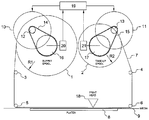
- the single figure shows schematically and functionally some components of a thermal transfer printer according to the invention, notably a supply spool 1 with tape to be un-wound and to be wound up onto a take-up spool 2.
- a supply spool 1 with tape to be un-wound and to be wound up onto a take-up spool 2.
- the tape 7 passes a printhead 18 which when energized causes ink to be transferred from the tape 7 to a substrate 9.
- a platen 8 provides counter pressure to the substrate 9 during activation of the printhead 18.
- the functionality of the supply spool 1 and the take-up spool 2 can also be reversed.
- the tape 7 is guided from the supply spool 1 to the take-up spool 2 along guides 3, 4, 5, 6.
- Rotation of the supply spool 1 and the take-up spool 2 is caused by a supply motor 10 and a take-up motor 11 that drive the supply spool 1 and take-up spool 2 either directly or through a system of belts 14, 15 and toothed wheels 12, 13 and 16, 17 or gears.
- the supply motor 10 and the take-up motor 11 are controlled by a spool drive controller 19 which takes account of the amount of tape 7 being present on the supply spool 1 and the take-up spool 2.
- the supply spool 1 and the take-up spool 2 are provided with position encoders 20, 21 that provide the spool drive controller 19 with positional information.
- Said encoders 20, 21 are connected to the spool drive controller 19 so as to arrange that the spool drive controller 19 controls the tape's tension, position and speed, wherein the spool drive controller 19 is embodied with field oriented control so as to drive the supply motor 10 and the take-up motor 11 to continuously and uninterruptedly control the motor torque of said motors 10, 11.
- the printhead 18 is driven by a motor (not shown) for driving the print-head 18 down to produce a force by pressing the substrate 9 down onto the counter pressure platen 8, wherein the motor for the printhead 18 is energized with field oriented control.
Landscapes
- Electronic Switches (AREA)
- Impression-Transfer Materials And Handling Thereof (AREA)
Description
- The invention relates to a thermal transfer printer for selectively transferring a meltable ink material carried on a tape to a substrate intended to receive ink from said tape for printing an image on the substrate, the printer comprising a supply spool for the tape, a take-up spool for the tape, and a printhead between the supply spool and the take-up spool, wherein the supply spool is driven by a supply motor and the take-up spool is driven by a take-up motor, and wherein the printer comprises a spool drive controller which is configured to energize the supply motor and the take-up motor so as to arrange that the tape is un-wound from the supply spool and wound onto the take-up spool.
- Such a thermal transfer printer is known from
US8,221,010 , and employs stepper motors for driving the supply spool and take-up spool. - A disadvantage of using stepper motors in the manner as proposed by
US8,221,010 is that positional resolution is limited by the step size of the motors, and that the tape is subjected to tension spikes each time the motors are energized. - It is an object of the invention to provide a thermal transfer printer with smooth tension control in the tape, as well as a high positional resolution. Also speed control of the tape should be of the highest standard.
- According to the invention the thermal transfer printer is provided with the features of at least one of the appended claims.
- In a first aspect of the invention the spool drive controller is embodied with field oriented control driving the supply motor and the take-up motor so as to continuously and uninterruptedly control motor torque of said motors, wherein the supply spool is provided with a supply encoder and the take-up spool is provided with a take-up encoder, which encoders provide positional information, and said encoders being connected to the spool drive controller so as to arrange that the spool drive controller controls the tape's tension, position and speed. Accordingly the loss of positional accuracy caused by skipped steps present in prior art stepper drive methods is avoided. Positional inaccuracy as present in the prior art leads to a number of problems including bad prints and potentially snapped tape. The term 'motor' is unspecified which means it can be any type of motor, albeit that there is a restriction in that the motor should be of the electric type such as for instance a permanent-magnet synchronous ac motor or a multi-coil synchronous motor. Field oriented control as such is known to the skilled person and requires no further elucidation. Suffice it to say that in "Field Oriented Control" the multiple motor input currents are adjusted independantly to set a specific magnitude and a specific angle between a stator magnetic field and a rotor magnetic field. Motor torque varies in proportion to the sine of this angle between stator and rotor fields, as well as their magnitudes. By continuously sensing the rotor position, the stator coil currents can be continuously adjusted to produce the required torque, whilst accounting for the continuous changes in the position of the rotor magnetic field as it moves (rotates).
- As mentioned smooth 'jerk-free' movement of the tape is important to stop the tape from breaking or snagging. By varying motor coil currents in a sinusoidal manner, there are no sudden changes, and jerky movements are completely avoided. Problems of mechanical resonance are also reduced with this technique as the periodic stimulation caused in the prior art by pulsed operation of the stepper motors, is absent.
- It is remarked that
US2016/0342125 teaches the application of vector control - also known as field oriented control -in a motor control apparatus of an image forming apparatus, i.e. a printer. Such a printer is a standalone apparatus for use in an office or home environment for printing text or images on a sheet of paper. This is distant from the thermal transfer printer of the invention which is designed and intended for selectively transferring a meltable ink material carried on a tape to a substrate intended to receive the ink from said tape for printing an image on the substrate. The thermal transfer printer of the invention is not suited for use in an office or home environment, but is used in an industrial setting, wherein it is integrated in a packaging or assembly line to print product and traceability information like expiration dates and bar codes on packaging material like LDPE film. A skilled person looking for improvement of the thermal transfer printer ofUS8,221,010 , would therefore not be incited to consult the teaching ofUS2016/0342125 . - It is further preferred that the printhead is driven by a motor for driving the printhead down to produce a force by pressing the substrate down onto a counter pressure platen, wherein the motor is energized with field oriented control.
- The invention will hereinafter be further elucidated with reference to the drawing of an exemplary embodiment of an apparatus according to the invention that is not limiting as to the appended claims.
- In the drawing:
- the figure shows an apparatus according to the invention.
- The single figure shows schematically and functionally some components of a thermal transfer printer according to the invention, notably a supply spool 1 with tape to be un-wound and to be wound up onto a take-
up spool 2. In transferring from the supply spool 1 to the take-up spool 2 thetape 7 passes aprinthead 18 which when energized causes ink to be transferred from thetape 7 to asubstrate 9. A platen 8 provides counter pressure to thesubstrate 9 during activation of theprinthead 18. The functionality of the supply spool 1 and the take-up spool 2 can also be reversed. - The
tape 7 is guided from the supply spool 1 to the take-up spool 2 along guides 3, 4, 5, 6. - Rotation of the supply spool 1 and the take-
up spool 2 is caused by asupply motor 10 and a take-up motor 11 that drive the supply spool 1 and take-up spool 2 either directly or through a system ofbelts toothed wheels - The
supply motor 10 and the take-up motor 11 are controlled by aspool drive controller 19 which takes account of the amount oftape 7 being present on the supply spool 1 and the take-up spool 2. Preferably for this purpose the supply spool 1 and the take-up spool 2 are provided withposition encoders spool drive controller 19 with positional information. Saidencoders spool drive controller 19 so as to arrange that thespool drive controller 19 controls the tape's tension, position and speed, wherein thespool drive controller 19 is embodied with field oriented control so as to drive thesupply motor 10 and the take-up motor 11 to continuously and uninterruptedly control the motor torque of saidmotors - According to another aspect of the invention the
printhead 18 is driven by a motor (not shown) for driving the print-head 18 down to produce a force by pressing thesubstrate 9 down onto the counter pressure platen 8, wherein the motor for theprinthead 18 is energized with field oriented control. - Although the invention has been discussed in the foregoing with reference to an exemplary embodiment of the apparatus of the invention, the invention is not restricted to this particular embodiment which can be varied in many ways without departing from the invention. The discussed exemplary embodiment shall therefore not be used to construe the appended claims strictly in accordance therewith. On the contrary the embodiment is merely intended to explain the wording of the appended claims without intent to limit the claims to this exemplary embodiment. The scope of protection of the invention shall therefore be construed in accordance with the appended claims only, wherein a possible ambiguity in the wording of the claims shall be resolved using this exemplary embodiment.
Claims (2)
- Thermal transfer printer for selectively transferring a meltable ink material carried on a tape (7) to a substrate intended to receive ink from said tape (7) for printing an image on the substrate (9), the printer comprising a supply spool (1) for the tape (7), a take-up spool (2) for the tape (7), and a printhead (18) between the supply spool (1) and the take-up spool (2), wherein the supply spool (1) is driven by a supply motor (10) and the take-up spool (2) is driven by a take-up motor (11), and wherein the printer comprises a spool drive controller (19) which is configured to energize the supply motor (10) and the take-up motor (11) so as to arrange that the tape (7) is unwound from the supply spool (1) and wound onto the take-up spool (2), characterized in that the spool drive controller (19) is embodied with field oriented control driving the supply motor (10) and the take-up motor (11) so as to continuously and uninterruptedly control motor torque of said motors, and that the supply spool (1) is provided with a supply encoder (20) and the take-up spool (2) is provided with a take-up encoder (21), which encoders (20, 21) provide positional information, and said encoders (20, 21) being connected to the spool drive controller (19) so as to arrange that the spool drive controller (19) controls the tape's tension, position and speed.
- Thermal transfer printer according to claim 1, characterized in that the printhead (18) is driven by a motor for driving the printhead (18) down to produce a force by pressing the substrate (9) down onto a counter pressure platen (8), wherein the motor is energized with field oriented control.
Applications Claiming Priority (2)
| Application Number | Priority Date | Filing Date | Title |
|---|---|---|---|
| NL2019160A NL2019160B1 (en) | 2017-07-03 | 2017-07-03 | Thermal transfer printer |
| PCT/NL2018/050346 WO2019009701A1 (en) | 2017-07-03 | 2018-05-28 | Thermal transfer printer |
Publications (2)
| Publication Number | Publication Date |
|---|---|
| EP3648979A1 EP3648979A1 (en) | 2020-05-13 |
| EP3648979B1 true EP3648979B1 (en) | 2021-05-05 |
Family
ID=59351033
Family Applications (1)
| Application Number | Title | Priority Date | Filing Date |
|---|---|---|---|
| EP18731543.7A Active EP3648979B1 (en) | 2017-07-03 | 2018-05-28 | Thermal transfer printer |
Country Status (7)
| Country | Link |
|---|---|
| US (1) | US20210155022A1 (en) |
| EP (1) | EP3648979B1 (en) |
| JP (1) | JP7157466B2 (en) |
| BR (1) | BR112019028279A2 (en) |
| ES (1) | ES2878351T3 (en) |
| NL (1) | NL2019160B1 (en) |
| WO (1) | WO2019009701A1 (en) |
Family Cites Families (13)
| Publication number | Priority date | Publication date | Assignee | Title |
|---|---|---|---|---|
| JPS62280063A (en) * | 1986-05-30 | 1987-12-04 | Fuji Xerox Co Ltd | Hand-driven type transfer device |
| JPH0725100A (en) * | 1993-07-08 | 1995-01-27 | Ricoh Co Ltd | Color thermal transfer recording device |
| JPH0872272A (en) * | 1994-09-01 | 1996-03-19 | Toshiba Corp | Recording device |
| JPH11198473A (en) * | 1998-01-12 | 1999-07-27 | Fuji Photo Film Co Ltd | Image forming apparatus |
| JP4238466B2 (en) * | 2000-08-08 | 2009-03-18 | 神鋼電機株式会社 | Color printing method and color printing apparatus |
| EP2298567B1 (en) * | 2000-09-11 | 2015-07-22 | Videojet Technologies, Inc. | Thermal transfer printer with a tape drive, and method for controlling it |
| JP2003276268A (en) * | 2002-03-26 | 2003-09-30 | Citizen Watch Co Ltd | Thermal printer |
| US6965212B1 (en) * | 2004-11-30 | 2005-11-15 | Honeywell International Inc. | Method and apparatus for field weakening control in an AC motor drive system |
| EP2134549B1 (en) * | 2007-03-31 | 2014-11-19 | Videojet Technologies, Inc. | Tape drive |
| JP5532997B2 (en) * | 2009-02-16 | 2014-06-25 | 大日本印刷株式会社 | Printing system |
| JP2012158032A (en) * | 2011-01-31 | 2012-08-23 | Dainippon Printing Co Ltd | Thermal transfer printer and transfer method |
| EP2744665B2 (en) * | 2011-08-15 | 2024-12-04 | Videojet Technologies Inc. | Thermal transfer printer |
| JP6557512B2 (en) * | 2015-05-20 | 2019-08-07 | キヤノン株式会社 | Motor control device, sheet conveying device, document reading device, and image forming device |
-
2017
- 2017-07-03 NL NL2019160A patent/NL2019160B1/en active
-
2018
- 2018-05-28 BR BR112019028279-3A patent/BR112019028279A2/en not_active Application Discontinuation
- 2018-05-28 JP JP2019572803A patent/JP7157466B2/en active Active
- 2018-05-28 EP EP18731543.7A patent/EP3648979B1/en active Active
- 2018-05-28 WO PCT/NL2018/050346 patent/WO2019009701A1/en not_active Ceased
- 2018-05-28 ES ES18731543T patent/ES2878351T3/en active Active
- 2018-05-28 US US16/628,044 patent/US20210155022A1/en not_active Abandoned
Also Published As
| Publication number | Publication date |
|---|---|
| EP3648979A1 (en) | 2020-05-13 |
| NL2019160B1 (en) | 2019-01-14 |
| ES2878351T3 (en) | 2021-11-18 |
| JP2020525323A (en) | 2020-08-27 |
| US20210155022A1 (en) | 2021-05-27 |
| BR112019028279A2 (en) | 2020-07-14 |
| JP7157466B2 (en) | 2022-10-20 |
| WO2019009701A1 (en) | 2019-01-10 |
Similar Documents
| Publication | Publication Date | Title |
|---|---|---|
| CN109562627B (en) | Printer with a movable platen | |
| EP2121335B1 (en) | Tape drive | |
| EP3533617B1 (en) | Thermal transfer printer and labelling machine | |
| EP2121332A1 (en) | Tape drive | |
| CN108349264B (en) | Printing apparatus and method | |
| CN103153633A (en) | Printing images on a retransfer material having a predisposed artifact | |
| JP5946325B2 (en) | Sensor moving device | |
| US20080217454A1 (en) | Tape drive | |
| CN101505964A (en) | Method and device for controlling the position of the numbering wheels of a numbering device | |
| US20210155022A1 (en) | Thermal transfer printer | |
| EP3060405B1 (en) | Tape drive and transfer printer | |
| GB2519525A (en) | Machine and method of operation | |
| EP3328652B1 (en) | Printing apparatus and method | |
| US11446919B2 (en) | Device for alphanumeric labeling of securities | |
| US20140225971A1 (en) | Printing Apparatus and Method of Operating a Printing Apparatus | |
| US11440333B2 (en) | Printing system | |
| JPS60157891A (en) | Image-forming device | |
| JP3675236B2 (en) | Paper feeder |
Legal Events
| Date | Code | Title | Description |
|---|---|---|---|
| STAA | Information on the status of an ep patent application or granted ep patent |
Free format text: STATUS: UNKNOWN |
|
| STAA | Information on the status of an ep patent application or granted ep patent |
Free format text: STATUS: THE INTERNATIONAL PUBLICATION HAS BEEN MADE |
|
| PUAI | Public reference made under article 153(3) epc to a published international application that has entered the european phase |
Free format text: ORIGINAL CODE: 0009012 |
|
| STAA | Information on the status of an ep patent application or granted ep patent |
Free format text: STATUS: REQUEST FOR EXAMINATION WAS MADE |
|
| 17P | Request for examination filed |
Effective date: 20200203 |
|
| AK | Designated contracting states |
Kind code of ref document: A1 Designated state(s): AL AT BE BG CH CY CZ DE DK EE ES FI FR GB GR HR HU IE IS IT LI LT LU LV MC MK MT NL NO PL PT RO RS SE SI SK SM TR |
|
| AX | Request for extension of the european patent |
Extension state: BA ME |
|
| DAV | Request for validation of the european patent (deleted) | ||
| DAX | Request for extension of the european patent (deleted) | ||
| GRAP | Despatch of communication of intention to grant a patent |
Free format text: ORIGINAL CODE: EPIDOSNIGR1 |
|
| STAA | Information on the status of an ep patent application or granted ep patent |
Free format text: STATUS: GRANT OF PATENT IS INTENDED |
|
| INTG | Intention to grant announced |
Effective date: 20210217 |
|
| GRAS | Grant fee paid |
Free format text: ORIGINAL CODE: EPIDOSNIGR3 |
|
| GRAA | (expected) grant |
Free format text: ORIGINAL CODE: 0009210 |
|
| STAA | Information on the status of an ep patent application or granted ep patent |
Free format text: STATUS: THE PATENT HAS BEEN GRANTED |
|
| AK | Designated contracting states |
Kind code of ref document: B1 Designated state(s): AL AT BE BG CH CY CZ DE DK EE ES FI FR GB GR HR HU IE IS IT LI LT LU LV MC MK MT NL NO PL PT RO RS SE SI SK SM TR |
|
| REG | Reference to a national code |
Ref country code: GB Ref legal event code: FG4D |
|
| REG | Reference to a national code |
Ref country code: CH Ref legal event code: EP |
|
| REG | Reference to a national code |
Ref country code: AT Ref legal event code: REF Ref document number: 1389340 Country of ref document: AT Kind code of ref document: T Effective date: 20210515 |
|
| REG | Reference to a national code |
Ref country code: IE Ref legal event code: FG4D |
|
| REG | Reference to a national code |
Ref country code: DE Ref legal event code: R096 Ref document number: 602018016739 Country of ref document: DE |
|
| REG | Reference to a national code |
Ref country code: NL Ref legal event code: FP |
|
| REG | Reference to a national code |
Ref country code: LT Ref legal event code: MG9D |
|
| REG | Reference to a national code |
Ref country code: AT Ref legal event code: MK05 Ref document number: 1389340 Country of ref document: AT Kind code of ref document: T Effective date: 20210505 |
|
| PG25 | Lapsed in a contracting state [announced via postgrant information from national office to epo] |
Ref country code: LT Free format text: LAPSE BECAUSE OF FAILURE TO SUBMIT A TRANSLATION OF THE DESCRIPTION OR TO PAY THE FEE WITHIN THE PRESCRIBED TIME-LIMIT Effective date: 20210505 Ref country code: HR Free format text: LAPSE BECAUSE OF FAILURE TO SUBMIT A TRANSLATION OF THE DESCRIPTION OR TO PAY THE FEE WITHIN THE PRESCRIBED TIME-LIMIT Effective date: 20210505 Ref country code: FI Free format text: LAPSE BECAUSE OF FAILURE TO SUBMIT A TRANSLATION OF THE DESCRIPTION OR TO PAY THE FEE WITHIN THE PRESCRIBED TIME-LIMIT Effective date: 20210505 Ref country code: AT Free format text: LAPSE BECAUSE OF FAILURE TO SUBMIT A TRANSLATION OF THE DESCRIPTION OR TO PAY THE FEE WITHIN THE PRESCRIBED TIME-LIMIT Effective date: 20210505 Ref country code: BG Free format text: LAPSE BECAUSE OF FAILURE TO SUBMIT A TRANSLATION OF THE DESCRIPTION OR TO PAY THE FEE WITHIN THE PRESCRIBED TIME-LIMIT Effective date: 20210805 |
|
| REG | Reference to a national code |
Ref country code: ES Ref legal event code: FG2A Ref document number: 2878351 Country of ref document: ES Kind code of ref document: T3 Effective date: 20211118 |
|
| PG25 | Lapsed in a contracting state [announced via postgrant information from national office to epo] |
Ref country code: GR Free format text: LAPSE BECAUSE OF FAILURE TO SUBMIT A TRANSLATION OF THE DESCRIPTION OR TO PAY THE FEE WITHIN THE PRESCRIBED TIME-LIMIT Effective date: 20210806 Ref country code: IS Free format text: LAPSE BECAUSE OF FAILURE TO SUBMIT A TRANSLATION OF THE DESCRIPTION OR TO PAY THE FEE WITHIN THE PRESCRIBED TIME-LIMIT Effective date: 20210905 Ref country code: SE Free format text: LAPSE BECAUSE OF FAILURE TO SUBMIT A TRANSLATION OF THE DESCRIPTION OR TO PAY THE FEE WITHIN THE PRESCRIBED TIME-LIMIT Effective date: 20210505 Ref country code: RS Free format text: LAPSE BECAUSE OF FAILURE TO SUBMIT A TRANSLATION OF THE DESCRIPTION OR TO PAY THE FEE WITHIN THE PRESCRIBED TIME-LIMIT Effective date: 20210505 Ref country code: PT Free format text: LAPSE BECAUSE OF FAILURE TO SUBMIT A TRANSLATION OF THE DESCRIPTION OR TO PAY THE FEE WITHIN THE PRESCRIBED TIME-LIMIT Effective date: 20210906 Ref country code: PL Free format text: LAPSE BECAUSE OF FAILURE TO SUBMIT A TRANSLATION OF THE DESCRIPTION OR TO PAY THE FEE WITHIN THE PRESCRIBED TIME-LIMIT Effective date: 20210505 Ref country code: NO Free format text: LAPSE BECAUSE OF FAILURE TO SUBMIT A TRANSLATION OF THE DESCRIPTION OR TO PAY THE FEE WITHIN THE PRESCRIBED TIME-LIMIT Effective date: 20210805 Ref country code: LV Free format text: LAPSE BECAUSE OF FAILURE TO SUBMIT A TRANSLATION OF THE DESCRIPTION OR TO PAY THE FEE WITHIN THE PRESCRIBED TIME-LIMIT Effective date: 20210505 |
|
| REG | Reference to a national code |
Ref country code: CH Ref legal event code: PL |
|
| PG25 | Lapsed in a contracting state [announced via postgrant information from national office to epo] |
Ref country code: EE Free format text: LAPSE BECAUSE OF FAILURE TO SUBMIT A TRANSLATION OF THE DESCRIPTION OR TO PAY THE FEE WITHIN THE PRESCRIBED TIME-LIMIT Effective date: 20210505 Ref country code: SK Free format text: LAPSE BECAUSE OF FAILURE TO SUBMIT A TRANSLATION OF THE DESCRIPTION OR TO PAY THE FEE WITHIN THE PRESCRIBED TIME-LIMIT Effective date: 20210505 Ref country code: SM Free format text: LAPSE BECAUSE OF FAILURE TO SUBMIT A TRANSLATION OF THE DESCRIPTION OR TO PAY THE FEE WITHIN THE PRESCRIBED TIME-LIMIT Effective date: 20210505 Ref country code: RO Free format text: LAPSE BECAUSE OF FAILURE TO SUBMIT A TRANSLATION OF THE DESCRIPTION OR TO PAY THE FEE WITHIN THE PRESCRIBED TIME-LIMIT Effective date: 20210505 Ref country code: DK Free format text: LAPSE BECAUSE OF FAILURE TO SUBMIT A TRANSLATION OF THE DESCRIPTION OR TO PAY THE FEE WITHIN THE PRESCRIBED TIME-LIMIT Effective date: 20210505 Ref country code: CH Free format text: LAPSE BECAUSE OF NON-PAYMENT OF DUE FEES Effective date: 20210531 Ref country code: CZ Free format text: LAPSE BECAUSE OF FAILURE TO SUBMIT A TRANSLATION OF THE DESCRIPTION OR TO PAY THE FEE WITHIN THE PRESCRIBED TIME-LIMIT Effective date: 20210505 Ref country code: LI Free format text: LAPSE BECAUSE OF NON-PAYMENT OF DUE FEES Effective date: 20210531 Ref country code: LU Free format text: LAPSE BECAUSE OF NON-PAYMENT OF DUE FEES Effective date: 20210528 |
|
| REG | Reference to a national code |
Ref country code: DE Ref legal event code: R097 Ref document number: 602018016739 Country of ref document: DE |
|
| REG | Reference to a national code |
Ref country code: BE Ref legal event code: MM Effective date: 20210531 |
|
| PLBE | No opposition filed within time limit |
Free format text: ORIGINAL CODE: 0009261 |
|
| STAA | Information on the status of an ep patent application or granted ep patent |
Free format text: STATUS: NO OPPOSITION FILED WITHIN TIME LIMIT |
|
| PG25 | Lapsed in a contracting state [announced via postgrant information from national office to epo] |
Ref country code: MC Free format text: LAPSE BECAUSE OF FAILURE TO SUBMIT A TRANSLATION OF THE DESCRIPTION OR TO PAY THE FEE WITHIN THE PRESCRIBED TIME-LIMIT Effective date: 20210505 |
|
| 26N | No opposition filed |
Effective date: 20220208 |
|
| PG25 | Lapsed in a contracting state [announced via postgrant information from national office to epo] |
Ref country code: IE Free format text: LAPSE BECAUSE OF NON-PAYMENT OF DUE FEES Effective date: 20210528 |
|
| PG25 | Lapsed in a contracting state [announced via postgrant information from national office to epo] |
Ref country code: IS Free format text: LAPSE BECAUSE OF FAILURE TO SUBMIT A TRANSLATION OF THE DESCRIPTION OR TO PAY THE FEE WITHIN THE PRESCRIBED TIME-LIMIT Effective date: 20210905 Ref country code: AL Free format text: LAPSE BECAUSE OF FAILURE TO SUBMIT A TRANSLATION OF THE DESCRIPTION OR TO PAY THE FEE WITHIN THE PRESCRIBED TIME-LIMIT Effective date: 20210505 |
|
| PG25 | Lapsed in a contracting state [announced via postgrant information from national office to epo] |
Ref country code: BE Free format text: LAPSE BECAUSE OF NON-PAYMENT OF DUE FEES Effective date: 20210531 |
|
| PG25 | Lapsed in a contracting state [announced via postgrant information from national office to epo] |
Ref country code: CY Free format text: LAPSE BECAUSE OF FAILURE TO SUBMIT A TRANSLATION OF THE DESCRIPTION OR TO PAY THE FEE WITHIN THE PRESCRIBED TIME-LIMIT Effective date: 20210505 |
|
| PG25 | Lapsed in a contracting state [announced via postgrant information from national office to epo] |
Ref country code: HU Free format text: LAPSE BECAUSE OF FAILURE TO SUBMIT A TRANSLATION OF THE DESCRIPTION OR TO PAY THE FEE WITHIN THE PRESCRIBED TIME-LIMIT; INVALID AB INITIO Effective date: 20180528 |
|
| PG25 | Lapsed in a contracting state [announced via postgrant information from national office to epo] |
Ref country code: MK Free format text: LAPSE BECAUSE OF FAILURE TO SUBMIT A TRANSLATION OF THE DESCRIPTION OR TO PAY THE FEE WITHIN THE PRESCRIBED TIME-LIMIT Effective date: 20210505 |
|
| PG25 | Lapsed in a contracting state [announced via postgrant information from national office to epo] |
Ref country code: MT Free format text: LAPSE BECAUSE OF FAILURE TO SUBMIT A TRANSLATION OF THE DESCRIPTION OR TO PAY THE FEE WITHIN THE PRESCRIBED TIME-LIMIT Effective date: 20210505 |
|
| PGFP | Annual fee paid to national office [announced via postgrant information from national office to epo] |
Ref country code: NL Payment date: 20250526 Year of fee payment: 8 |
|
| PGFP | Annual fee paid to national office [announced via postgrant information from national office to epo] |
Ref country code: DE Payment date: 20250529 Year of fee payment: 8 |
|
| PGFP | Annual fee paid to national office [announced via postgrant information from national office to epo] |
Ref country code: GB Payment date: 20250527 Year of fee payment: 8 Ref country code: ES Payment date: 20250602 Year of fee payment: 8 |
|
| PGFP | Annual fee paid to national office [announced via postgrant information from national office to epo] |
Ref country code: IT Payment date: 20250521 Year of fee payment: 8 |
|
| PGFP | Annual fee paid to national office [announced via postgrant information from national office to epo] |
Ref country code: FR Payment date: 20250526 Year of fee payment: 8 |
|
| PGFP | Annual fee paid to national office [announced via postgrant information from national office to epo] |
Ref country code: TR Payment date: 20250515 Year of fee payment: 8 |