EP3648907B1 - Antifouling accessory for field deployed sensors and instruments - Google Patents
Antifouling accessory for field deployed sensors and instruments Download PDFInfo
- Publication number
- EP3648907B1 EP3648907B1 EP18829159.5A EP18829159A EP3648907B1 EP 3648907 B1 EP3648907 B1 EP 3648907B1 EP 18829159 A EP18829159 A EP 18829159A EP 3648907 B1 EP3648907 B1 EP 3648907B1
- Authority
- EP
- European Patent Office
- Prior art keywords
- sensor
- foam
- instrument
- copper
- sensor device
- Prior art date
- Legal status (The legal status is an assumption and is not a legal conclusion. Google has not performed a legal analysis and makes no representation as to the accuracy of the status listed.)
- Active
Links
Images




Classifications
-
- G—PHYSICS
- G01—MEASURING; TESTING
- G01D—MEASURING NOT SPECIALLY ADAPTED FOR A SPECIFIC VARIABLE; ARRANGEMENTS FOR MEASURING TWO OR MORE VARIABLES NOT COVERED IN A SINGLE OTHER SUBCLASS; TARIFF METERING APPARATUS; MEASURING OR TESTING NOT OTHERWISE PROVIDED FOR
- G01D11/00—Component parts of measuring arrangements not specially adapted for a specific variable
- G01D11/24—Housings ; Casings for instruments
- G01D11/245—Housings for sensors
-
- B—PERFORMING OPERATIONS; TRANSPORTING
- B08—CLEANING
- B08B—CLEANING IN GENERAL; PREVENTION OF FOULING IN GENERAL
- B08B17/00—Methods preventing fouling
- B08B17/02—Preventing deposition of fouling or of dust
- B08B17/04—Preventing deposition of fouling or of dust by using removable coverings
-
- G—PHYSICS
- G01—MEASURING; TESTING
- G01C—MEASURING DISTANCES, LEVELS OR BEARINGS; SURVEYING; NAVIGATION; GYROSCOPIC INSTRUMENTS; PHOTOGRAMMETRY OR VIDEOGRAMMETRY
- G01C13/00—Surveying specially adapted to open water, e.g. sea, lake, river or canal
-
- H—ELECTRICITY
- H05—ELECTRIC TECHNIQUES NOT OTHERWISE PROVIDED FOR
- H05K—PRINTED CIRCUITS; CASINGS OR CONSTRUCTIONAL DETAILS OF ELECTRIC APPARATUS; MANUFACTURE OF ASSEMBLAGES OF ELECTRICAL COMPONENTS
- H05K5/00—Casings, cabinets or drawers for electric apparatus
- H05K5/02—Details
- H05K5/03—Covers
-
- G—PHYSICS
- G01—MEASURING; TESTING
- G01N—INVESTIGATING OR ANALYSING MATERIALS BY DETERMINING THEIR CHEMICAL OR PHYSICAL PROPERTIES
- G01N33/00—Investigating or analysing materials by specific methods not covered by groups G01N1/00 - G01N31/00
- G01N33/18—Water
Definitions
- This invention relates to a sensor for measuring parameters related to water, e.g., in a river, a stream, a lake, an estuary, a sea, an ocean, etc.
- US 2014/ 151 308 A1 discloses a microprocessor pre-programmable autonomous device with biofouling control and method for monitoring aquatic environment by disposing environmental sensors in a sensor chamber which programmably opens for allowing direct communication between the sensors and the fluid of interest for sampling and which is closed after the sampling sequence is completed to create an anti-fouling environment in the sensor chamber by dissolving a biocide salt in the chamber.
- JP 2008-261 766 discloses a water quality analysis device according to the preamble of claim 1, comprising a sensor section with one or more measuring sensors inside.
- a tip of the sensor section has a double wall structure consisting of an inner wall and an outer wall separated from each other by a clearance.
- An inner wall through hole and an outer wall through hole disposed in the inner wall and the outer wall, respectively, are arranged at mutually different positions.
- the outer wall is made of elastic material.
- KR 10-2016-0124415 A relates to a sensor for measuring water quality having a seawater inlet cap.
- the sensor comprises: a main body housing; a lower cap which is connected in order that a lower opening of the main body housing is sealed, and where a plurality of lower connector modules are installed; an upper cap which is connected in order that an upper opening of the main body housing is sealed, and where a plurality of upper connector modules are installed; a plurality of sensor modules connected to the lower connector modules; a sensor module housing which accommodates the sensor modules by being hollow from an upper side to a lower side, and where the upper side is connected to the lower cap and a seawater outlet hole is formed on an outer circumference surface of the upper side; and a seawater inlet cap which is connected to cover a lower opening of the sensor module housing.
- Current technology offers sensor protection by use of mechanical wiping, copper laden accessories and/or UV irradiation. The current accessories create a hostile environment for biofouling agents such as barnacles and the like.
- Tedious sensor deployment preparation involves wrapping sensors/instruments in copper tape and typically only offers one use per deployment. UV irradiation requires external power, which limits deployment site selection due to the power requirements of the system.
- the present invention provides a reusable antifouling accessory for protecting field sensors or instruments to control fouling build-up.
- the antifouling accessory is installed around the outside of the one or more sensors or instruments, minimizing available sensor/instrument surface area for fouling. Minimizing the available surface area for the films to adhere, greatly decreases the amount of biological growth which translates into decreased time spent cleaning post deployment.
- one or more antifouling accessories may include the following materials:
- the antifouling accessories could be secured by the following methods or combination therein:
- a sensor device for deploying in an environmental field having macro-organisms and for performing environmental monitoring, featuring a sensor body and an antifouling accessory, e.g., such as an antifouling device or guard.
- the sensor body includes at least one instrument or sensor configured to sense to one or more environmental conditions in the environmental field and provide signalling containing information about the one or more environmental conditions sensed.
- the antifouling device or guard is configured to couple to the sensor body, cover part of the at least one instrument or sensor, and protect a cover part of the at least one instrument or sensor from the macro-organisms.
- the sensor device includes a foam barrier configured between the antifouling guard or device and the instrument or sensor.
- the present invention may include one or more of the following features:
- Advantages of the antifouling accessory according to the present invention may include:
- Figure 1 shows a sensor device generally indicated as 10 for deploying in an environmental field having macro-organisms and for performing environmental monitoring of water, e.g., in a river, a stream, a lake, an estuary, a sea, an ocean, etc.
- the sensor device 10 includes a sensor body generally indicated as 12 and an antifouling accessory, e.g., such as an antifouling device or guard generally indicated as 14.
- the sensor body 12 includes a sensor body portion 12a and instruments or sensors, one of which is labelled 16.
- the antifouling device or guard 14 may take the form of a plastic antifouling body 18 with a copper insert 20 fastened with screws, one of which is labelled 22.
- Figure 2 shows the sensor device 10 having the antifouling device or guard 14 coupled to the sensor body 12.
- two halves of the antifouling device or guard 14 are labelled 24, 26 and coupled together with the screws, one of which is labelled 28.
- Figure 3 shows the sensor device 10 having the antifouling device or guard 14 having the two halves 24, 26 coupled to the sensor body 12 having the instruments or sensors 16.
- the covered part of the sensors or instruments 16 is generally indicated by 16a, which points to the area of the sensors or instruments 16 covered and protected by the antifouling device or guard 14.
- the covered part 16a of the sensors or instruments 16 is the area underneath the antifouling device or guard 14.
- Figure 4 shows the sensor device 10 having the antifouling device or guard 14 coupled to the sensor body 12,
- the antifouling device or guard 14 may take the form of a copper, brass alloy or plastic guard configured to protect the sensors/instruments 16 from large debris, e.g., such as macro-organisms in the water.
- the sensor device 10 includes a foam barrier 30 which may surround the body that protects the one or more sensors/instruments 16.
- the antifouling device or guard 14 may include openings/orifices configured or formed therein, one of which is labelled 32.
- the covered part of the sensors or instruments is the area of the sensors or instruments covered and protected by the foam barrier 30.
- the covered part is the area underneath the foam barrier 30.
- Figure 5 shows the sensor device 10 having the antifouling device or guard 14 coupled to the sensor body 12.
- the sensors/instruments 16 are collectively surrounded by one piece of foam 30 configured to provide a foam barrier to protect the sensors/instruments 16 from macro-organisms.
- Figures 6A and 6B show a sensor device 10 having the antifouling device or guard 14 coupled to the sensor body 12. e.g., including showing a guard cutaway to reveal the one or more sensors/instruments 16 surrounded in the foam barrier 30 and covered by a tubing 34.
- the tubing 34 may include, or take the form of, a heat shrink tubing.
- Figure 7 shows a single sensor/instrument 16 surrounded or wrapped in an individual piece of foam 30, and having an individual heat shrink tubing 36 used to hold the individual pieces of foam 30 in place.
- each individual sensor/instrument 16 may be surrounded or wrapped in a respective individual piece of foam 30.
- the individual foam wrapped sensor/instruments 16 are also collectively wrapped with a further outer foam barrier, e.g., consistent with that shown in Figures 4 , 5 and 6A and 6B , so as to form a double foam inner/outer layer of protection.
- the instruments or sensors 16 may be configured to sense to one or more environmental conditions in the environmental field and provide signalling containing information about the one or more environmental conditions sensed.
- Instruments or sensors like element 16 are known in the art, and the scope of invention is not intended to be limited to any particular type or kind either now known or later developed in the future.
- macro-organisms are understood to be organisms that are large enough to be seen by an unaided eye. No optical instruments, such as microscopes and lens, are necessary to see them.
- macro-organisms may include macrobenthos such as crustaceans and mollusks in the sea floor, barnacle, and millipedes, snails, and mites in soil.
Landscapes
- General Physics & Mathematics (AREA)
- Engineering & Computer Science (AREA)
- Physics & Mathematics (AREA)
- Life Sciences & Earth Sciences (AREA)
- Remote Sensing (AREA)
- Radar, Positioning & Navigation (AREA)
- Hydrology & Water Resources (AREA)
- Microelectronics & Electronic Packaging (AREA)
- Health & Medical Sciences (AREA)
- Chemical & Material Sciences (AREA)
- Food Science & Technology (AREA)
- General Health & Medical Sciences (AREA)
- Immunology (AREA)
- Pathology (AREA)
- Biochemistry (AREA)
- Analytical Chemistry (AREA)
- Medicinal Chemistry (AREA)
- Testing Or Calibration Of Command Recording Devices (AREA)
- Catching Or Destruction (AREA)
- Geophysics And Detection Of Objects (AREA)
Description
- This application claims benefit to provisional patent application serial no.
62/529,594, filed 7 July 2017 - This invention relates to a sensor for measuring parameters related to water, e.g., in a river, a stream, a lake, an estuary, a sea, an ocean, etc.
-
US 2014/ 151 308 A1 discloses a microprocessor pre-programmable autonomous device with biofouling control and method for monitoring aquatic environment by disposing environmental sensors in a sensor chamber which programmably opens for allowing direct communication between the sensors and the fluid of interest for sampling and which is closed after the sampling sequence is completed to create an anti-fouling environment in the sensor chamber by dissolving a biocide salt in the chamber. -
JP 2008-261 766 -
KR 10-2016-0124415 A - Biofilms condition the surface of any sensor or instrument, making favourable conditions for macro-organisms, such as barnacles to grow. Minimizing fouling and specifically, biofouling, in environmental monitoring systems is a complicated problem that often limits the deployment length of field sensors or field instruments. Current technology offers sensor protection by use of mechanical wiping, copper laden accessories and/or UV irradiation. The current accessories create a hostile environment for biofouling agents such as barnacles and the like. Tedious sensor deployment preparation involves wrapping sensors/instruments in copper tape and typically only offers one use per deployment. UV irradiation requires external power, which limits deployment site selection due to the power requirements of the system.
- In view of this, there is a need in the industry for a better way for minimizing fouling and specifically, biofouling, in environmental monitoring systems.
- The object is solved by a sensor device comprising the features of claim 1.
- The present invention provides a reusable antifouling accessory for protecting field sensors or instruments to control fouling build-up. The antifouling accessory is installed around the outside of the one or more sensors or instruments, minimizing available sensor/instrument surface area for fouling. Minimizing the available surface area for the films to adhere, greatly decreases the amount of biological growth which translates into decreased time spent cleaning post deployment.
- According to the present invention, one or more antifouling accessories may include the following materials:
- Polymer/plastic;
- Copper;
- Brass alloy;
- Foam;
- A combination of plastic and copper, e.g., including:
- Plastic with an outer layer of copper,
- Copper impregnated plastic, and
- Plastic with a copper piece near the sensing area or critical part of the instrument;
- A combination of foam and copper, e.g., including:
- Foam with an outer layer of copper,
- Copper impregnated foam, and
- Foam with a copper piece near the sensing area or critical part of the instrument.
- By way of example, the antifouling accessories could be secured by the following methods or combination therein:
- Zip/cable ties,
- Screws,
- Epoxy,
- Tape,
- Press fit,
- Interlocking mechanisms,
- Heat shrink wrap, and
- O-rings.
- According to the present invention, a sensor device is proposed for deploying in an environmental field having macro-organisms and for performing environmental monitoring, featuring a sensor body and an antifouling accessory, e.g., such as an antifouling device or guard.
- The sensor body includes at least one instrument or sensor configured to sense to one or more environmental conditions in the environmental field and provide signalling containing information about the one or more environmental conditions sensed.
- The antifouling device or guard is configured to couple to the sensor body, cover part of the at least one instrument or sensor, and protect a cover part of the at least one instrument or sensor from the macro-organisms.
- The sensor device includes a foam barrier configured between the antifouling guard or device and the instrument or sensor.
- The present invention may include one or more of the following features:
- The antifouling device or guard may include an antifouling body having two halves or members that fasten together, e.g., via one set of screws or fasteners.
- The antifouling device or guard may also include a copper insert, e.g., fastened to the antifouling body via another set of screws.
- The two halves or members may be made of plastic, brass alloy, copper, plastic with an outer layer of copper, copper impregnated with plastic, plastic with a copper piece near a sensing area of the instrument or sensor.
- The two members may be fastened together with screws, zip cable ties, epoxy, tape, or heat shrink wrap.
- The two members may be configured to press fit together.
- The foam barrier may include a foam with an outer layer of copper, a copper impregnated foam, a foam with a copper piece near a sensing area of the at least one instrument or sensor.
- The foam barrier may include a foam that surrounds the at least one instrument or sensor and a heat shrink tubing to hold the foam in place.
- The at least one instrument or sensor may include multiple instruments or sensors; and the foam barrier may include one piece of foam that collectively surrounds the multiple instruments or sensors and a heat shrink tubing to hold the foam in place.
- The at least one instrument or sensor may include multiple instruments or sensors; and the foam barrier may include individual pieces of foam that respectively surrounds each of the multiple instruments or sensors and individual heat shrink tubing to hold the individual pieces of foam in place.
- Advantages of the antifouling accessory according to the present invention, e.g., may include:
- Reusability,
- Quick installation,
- Field changeability,
- Inexpensive,
- Durability,
- Easily arranged to accessorize existing field platforms as well as future field platforms, and
- Easily cleaned by conventional methods.
- The drawing, which are not necessarily drawn to scale, includes
Figures 1 -7 , as follows: -
Figure 1 is an exploded perspective view of a sensor device for deploying in an environmental field having macro-organisms and for performing environmental monitoring, having a sensor body and an antifouling device or guard, where the sensor body includes instruments or sensors, and where the antifouling device or guard takes the form of a plastic antifouling body with a copper insert fastened with screws, according to some embodiments of the present invention. -
Figure 2 is a photograph showing a sensor device having an antifouling device or guard coupled to a sensor body, where the antifouling device or guard takes the form of a plastic body having two halves coupled together with screws, according to some embodiments of the present invention. -
Figure 3 is a computer rendition of a sensor device having an antifouling device or guard coupled to a sensor body, where the antifouling device or guard is shown in phantom surrounding the instruments or sensors of the sensor body, according to some embodiments of the present invention. -
Figure 4 is a photograph showing a sensor device having an antifouling device or guard coupled to a sensor body, where the antifouling device or guard takes the form of a copper, brass alloy or plastic guard that protects the sensors/instruments from large debris, and where the sensor device includes a foam barrier surrounding body that protects the sensors/instruments, according to some embodiments of the present invention. -
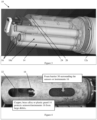
Figure 5 is a photograph showing an inside view of a sensor device having an antifouling device or guard coupled to a sensor body, where the sensors/instruments are surrounded in foam, according to some embodiments of the present invention. -
Figure 6A is a photograph of a sensor device having an antifouling device or guard coupled to a sensor body, including showing a guard cutaway to reveal sensors/instruments surrounded in foam and covered by tubing (e.g., a heat shrink tubing), according to some embodiments of the present invention. -
Figure 6B is an enlarged view of part of the photograph inFigure 6A , including the part having the guard cutaway to reveal the sensors/instruments surrounded in the foam, according to some embodiments of the present invention. -
Figure 7 is a photograph showing a single sensor/instrument individually surrounded in foam with a heat shrink tubing used to hold the foam in place, according to some embodiments of the present invention. - To reduce clutter in the drawing, each Figure in the drawing does not necessarily include every reference label for every element shown therein.
- By way of example,
Figure 1 shows a sensor device generally indicated as 10 for deploying in an environmental field having macro-organisms and for performing environmental monitoring of water, e.g., in a river, a stream, a lake, an estuary, a sea, an ocean, etc. Thesensor device 10 includes a sensor body generally indicated as 12 and an antifouling accessory, e.g., such as an antifouling device or guard generally indicated as 14. Thesensor body 12 includes asensor body portion 12a and instruments or sensors, one of which is labelled 16. By way of example, the antifouling device orguard 14 may take the form of aplastic antifouling body 18 with acopper insert 20 fastened with screws, one of which is labelled 22. -
Figure 2 shows thesensor device 10 having the antifouling device orguard 14 coupled to thesensor body 12. InFigure 2 , two halves of the antifouling device orguard 14 are labelled 24, 26 and coupled together with the screws, one of which is labelled 28. -
Figure 3 shows thesensor device 10 having the antifouling device orguard 14 having the twohalves sensor body 12 having the instruments orsensors 16. InFigure 3 , the covered part of the sensors orinstruments 16 is generally indicated by 16a, which points to the area of the sensors orinstruments 16 covered and protected by the antifouling device orguard 14. In effect, thecovered part 16a of the sensors orinstruments 16 is the area underneath the antifouling device orguard 14. - By way of further example,
Figure 4 shows thesensor device 10 having the antifouling device orguard 14 coupled to thesensor body 12, The antifouling device orguard 14 may take the form of a copper, brass alloy or plastic guard configured to protect the sensors/instruments 16 from large debris, e.g., such as macro-organisms in the water. Thesensor device 10 includes afoam barrier 30 which may surround the body that protects the one or more sensors/instruments 16. The antifouling device orguard 14 may include openings/orifices configured or formed therein, one of which is labelled 32. - Consistent with that set forth in relation to that shown in
Figure 3 , the covered part of the sensors or instruments is the area of the sensors or instruments covered and protected by thefoam barrier 30. In effect, the covered part is the area underneath thefoam barrier 30. -
Figure 5 shows thesensor device 10 having the antifouling device orguard 14 coupled to thesensor body 12. The sensors/instruments 16 are collectively surrounded by one piece offoam 30 configured to provide a foam barrier to protect the sensors/instruments 16 from macro-organisms. -
Figures 6A and 6B show asensor device 10 having the antifouling device orguard 14 coupled to thesensor body 12. e.g., including showing a guard cutaway to reveal the one or more sensors/instruments 16 surrounded in thefoam barrier 30 and covered by atubing 34. By way of example, thetubing 34 may include, or take the form of, a heat shrink tubing. -
Figure 7 shows a single sensor/instrument 16 surrounded or wrapped in an individual piece offoam 30, and having an individual heat shrinktubing 36 used to hold the individual pieces offoam 30 in place. In this embodiment, each individual sensor/instrument 16 may be surrounded or wrapped in a respective individual piece offoam 30. Embodiments are also envisioned, in which the individual foam wrapped sensor/instruments 16 are also collectively wrapped with a further outer foam barrier, e.g., consistent with that shown inFigures 4 ,5 and6A and 6B , so as to form a double foam inner/outer layer of protection. - By way of example, the instruments or
sensors 16 may be configured to sense to one or more environmental conditions in the environmental field and provide signalling containing information about the one or more environmental conditions sensed. Instruments or sensors likeelement 16 are known in the art, and the scope of invention is not intended to be limited to any particular type or kind either now known or later developed in the future. - As one skilled in the art would appreciate, macro-organisms are understood to be organisms that are large enough to be seen by an unaided eye. No optical instruments, such as microscopes and lens, are necessary to see them. By way of example, macro-organisms may include macrobenthos such as crustaceans and mollusks in the sea floor, barnacle, and millipedes, snails, and mites in soil.
Claims (10)
- A sensor device (10) for deploying in an environmental field having macro-organisms and for performing environmental monitoring, comprising:a sensor body (12) having at least one instrument or sensor (16) configured to sense to one or more environmental conditions in the environmental field and provide signaling containing information about the one or more environmental conditions sensed; andan antifouling device or guard (14) configured to couple to the sensor body (12), cover part (16a) of the at least one instrument or sensor (16), and protect the covered part (16a) of the at least one instrument or sensor (16) from the macro-organisms,wherein the antifouling device or guard (14) comprises an antifouling body (18) having two members (18, 20; 24, 26) that fasten together,characterised in that the sensor device (10) comprises a foam barrier (30) configured between the antifouling device or guard (14) and the at least one instrument or sensor (16).
- The sensor device (10) according to claim 1, wherein the two members (18, 20; 24, 26) are made of plastic, brass alloy, copper, or plastic with an outer layer of copper, copper impregnated with plastic, or plastic with a copper piece near a sensing area of the at least one instrument or sensor (16).
- The sensor device (10) according to claim 1 or 2, wherein the two members (18, 20; 24, 26) are fastened together with screws (22; 28), zip cable ties, epoxy, tape, or heat shrink wrap (36).
- The sensor device (10) according to claim 1 or 2, wherein the two members (18, 20; 24, 26) are configured to be press fit together.
- The sensor device (10) according to one of the preceding claims, wherein the foam barrier (30) comprises a foam having an outer layer of copper, a copper impregnated foam, a foam with a copper piece near a sensing area of the instrument or sensor (16).
- The sensor device (10) according to one of the preceding claims, wherein the foam barrier (30) comprises a foam that surrounds the at least one instrument or sensor (16) and a heat shrink tubing (36) to hold the foam in place.
- The sensor device (10) according to one of the preceding claims, whereinthe at least one instrument or sensor (16) comprises multiple instruments or sensors; andthe foam barrier (30) comprises one piece of foam that collectively surrounds the multiple instruments or sensors (16) and a heat shrink tubing (36) to hold the foam in place.
- The sensor device (10) according to one of the preceding claims, whereinthe at least one instrument or sensor (16) comprises multiple instruments or sensors; andthe foam barrier (30) comprises individual pieces of foam that respectively surround each of the multiple instruments or sensors (16) and individual heat shrink tubing (36) to hold the individual pieces of foam in place.
- The sensor device (10) according to one of the preceding claims, wherein the sensor device (10) comprises a copper insert (20) coupled to the two members (18, 20; 24, 26).
- The sensor device (10) according to claim 9, wherein the sensor device (10) comprises fasteners configured to fasten together the copper insert (20) and the two members (18, 20; 24, 26).
Applications Claiming Priority (2)
| Application Number | Priority Date | Filing Date | Title |
|---|---|---|---|
| US201762529594P | 2017-07-07 | 2017-07-07 | |
| PCT/US2018/041231 WO2019010478A1 (en) | 2017-07-07 | 2018-07-09 | Antifouling accessory for field deployed sensors and instruments |
Publications (4)
| Publication Number | Publication Date |
|---|---|
| EP3648907A1 EP3648907A1 (en) | 2020-05-13 |
| EP3648907A4 EP3648907A4 (en) | 2021-04-07 |
| EP3648907C0 EP3648907C0 (en) | 2023-11-29 |
| EP3648907B1 true EP3648907B1 (en) | 2023-11-29 |
Family
ID=64950419
Family Applications (1)
| Application Number | Title | Priority Date | Filing Date |
|---|---|---|---|
| EP18829159.5A Active EP3648907B1 (en) | 2017-07-07 | 2018-07-09 | Antifouling accessory for field deployed sensors and instruments |
Country Status (8)
| Country | Link |
|---|---|
| US (1) | US10908000B2 (en) |
| EP (1) | EP3648907B1 (en) |
| KR (1) | KR102263667B1 (en) |
| CN (1) | CN110914001B (en) |
| AU (1) | AU2018298218B2 (en) |
| BR (1) | BR112020000353B1 (en) |
| CA (1) | CA3069141C (en) |
| WO (1) | WO2019010478A1 (en) |
Families Citing this family (3)
| Publication number | Priority date | Publication date | Assignee | Title |
|---|---|---|---|---|
| WO2021236720A1 (en) * | 2020-05-20 | 2021-11-25 | Ysi, Inc. | Extended solid angle turbidity sensor |
| EP4251971A4 (en) | 2020-11-30 | 2025-01-22 | H2Ok Innovations Inc. | Methods and systems for monitoring fluids |
| EP4151957A1 (en) * | 2021-09-17 | 2023-03-22 | Vorwerk & Co. Interholding GmbH | Sensor assembly and protective layer |
Citations (2)
| Publication number | Priority date | Publication date | Assignee | Title |
|---|---|---|---|---|
| US20120243370A1 (en) * | 2008-07-28 | 2012-09-27 | Sercel | Seismic streamer formed of sections comprising a main sheath covered with an external sheath formed using a thermoplastic material loaded with a biocide material |
| US20140247690A1 (en) * | 2013-03-04 | 2014-09-04 | Cgg Services Sa | Antifouling protective skin section for seismic survey equipment and related methods |
Family Cites Families (24)
| Publication number | Priority date | Publication date | Assignee | Title |
|---|---|---|---|---|
| DE2203475C3 (en) * | 1972-01-26 | 1980-11-20 | Norddeutsche Seekabelwerke Ag | Surface coating of a sensor for underwater probes |
| US5321268A (en) * | 1993-02-22 | 1994-06-14 | Northwest Marine Technology, Inc. | Undersea probe |
| US5633460A (en) * | 1994-07-14 | 1997-05-27 | Nec Corporation | Ocean environment monitoring system and method for controlling the same |
| AU757644B2 (en) * | 1998-09-09 | 2003-02-27 | Kuraray Co., Ltd. | Antifouling structure having effect of preventing attachment of aquatic organisms thereto |
| US7341695B1 (en) * | 2003-12-16 | 2008-03-11 | Stuart Garner | Anti-fouling apparatus and method |
| JP4943923B2 (en) | 2007-04-13 | 2012-05-30 | 株式会社堀場製作所 | Water quality analyzer |
| US20140151308A1 (en) | 2007-08-07 | 2014-06-05 | Vincent M. Kelly | Autonomous Device with Biofouling Control and Method for Monitoring Aquatic Environment |
| US9562163B2 (en) * | 2009-02-26 | 2017-02-07 | Severn Marine Technologies, Llc | Optically clear biofouling resistant compositions and methods for marine instruments |
| US20110056276A1 (en) * | 2009-09-09 | 2011-03-10 | Hach Company | Anti-fouling submersible liquid sensor and method |
| EP2502094A4 (en) * | 2009-12-10 | 2017-03-29 | Geco Technology B.V. | Systems and methods for marine anti-fouling |
| US9133727B2 (en) * | 2010-01-12 | 2015-09-15 | Advanced F.M.E. Products | Sensor foreign material exclusion devices and methods |
| US20110174207A1 (en) * | 2010-01-21 | 2011-07-21 | Pgs Geophysical As | System and method for using copper coating to prevent marine growth on towed geophysical equipment |
| US8429952B1 (en) * | 2010-02-02 | 2013-04-30 | Campbell Scientific, Inc. | Sensor with antifouling control |
| US8514664B2 (en) * | 2010-04-16 | 2013-08-20 | Pgs Geophysical As | System and method for gathering marine geophysical data |
| US20170217549A9 (en) * | 2010-07-06 | 2017-08-03 | Biofouling Solutions, Inc. | Formable aquatic coverings for preventing biofouling |
| US20120176858A1 (en) * | 2011-01-11 | 2012-07-12 | Pgs Geophysical As | Co-extruded marine sensor cable jacket with anti-fouling properties |
| US9116253B2 (en) * | 2011-01-11 | 2015-08-25 | Pgs Geophysical As | System and method for using biocide coating to prevent marine growth on geophysical equipment |
| US8998535B2 (en) * | 2012-05-18 | 2015-04-07 | Pgs Geophysical As | Method and system of retriever systems for marine geophysical survey sensor streamers |
| AU2013213703A1 (en) * | 2012-08-13 | 2014-02-27 | Cgg Services Sa | Antifouling removable streamer second skin and method of mounting thereof |
| US9857487B2 (en) * | 2012-10-01 | 2018-01-02 | Westerngeco Llc | Solid marine seismic streamers |
| US9465127B2 (en) * | 2013-05-07 | 2016-10-11 | Pgs Geophysical As | Disposable antifouling covers for geophysical survey equipment |
| US9709689B2 (en) * | 2014-02-07 | 2017-07-18 | Pgs Geophysical As | Geophysical cable preparation for antifouling paint |
| CN205874882U (en) * | 2016-07-07 | 2017-01-11 | 江南大学 | Bury flexible damping protective structure of formula way area sensor |
| KR20160124415A (en) | 2016-10-18 | 2016-10-27 | 주식회사 과학기술분석센타 | A sensor apparatus for measuring quality of water with sea-inflow-cap |
-
2018
- 2018-07-09 US US16/030,008 patent/US10908000B2/en active Active
- 2018-07-09 CN CN201880045580.2A patent/CN110914001B/en active Active
- 2018-07-09 EP EP18829159.5A patent/EP3648907B1/en active Active
- 2018-07-09 AU AU2018298218A patent/AU2018298218B2/en active Active
- 2018-07-09 BR BR112020000353-0A patent/BR112020000353B1/en active IP Right Grant
- 2018-07-09 CA CA3069141A patent/CA3069141C/en active Active
- 2018-07-09 WO PCT/US2018/041231 patent/WO2019010478A1/en not_active Ceased
- 2018-07-09 KR KR1020207003750A patent/KR102263667B1/en active Active
Patent Citations (2)
| Publication number | Priority date | Publication date | Assignee | Title |
|---|---|---|---|---|
| US20120243370A1 (en) * | 2008-07-28 | 2012-09-27 | Sercel | Seismic streamer formed of sections comprising a main sheath covered with an external sheath formed using a thermoplastic material loaded with a biocide material |
| US20140247690A1 (en) * | 2013-03-04 | 2014-09-04 | Cgg Services Sa | Antifouling protective skin section for seismic survey equipment and related methods |
Also Published As
| Publication number | Publication date |
|---|---|
| CN110914001A (en) | 2020-03-24 |
| EP3648907A1 (en) | 2020-05-13 |
| AU2018298218B2 (en) | 2020-11-19 |
| WO2019010478A1 (en) | 2019-01-10 |
| CN110914001B (en) | 2022-06-24 |
| US20190063965A1 (en) | 2019-02-28 |
| EP3648907C0 (en) | 2023-11-29 |
| EP3648907A4 (en) | 2021-04-07 |
| BR112020000353B1 (en) | 2021-07-20 |
| CA3069141C (en) | 2021-06-22 |
| BR112020000353A2 (en) | 2020-07-14 |
| KR102263667B1 (en) | 2021-06-10 |
| AU2018298218A1 (en) | 2020-01-30 |
| CA3069141A1 (en) | 2019-01-10 |
| US10908000B2 (en) | 2021-02-02 |
| KR20200028426A (en) | 2020-03-16 |
Similar Documents
| Publication | Publication Date | Title |
|---|---|---|
| EP3648907B1 (en) | Antifouling accessory for field deployed sensors and instruments | |
| US11980172B2 (en) | Systems and methods for the cultivation of target product | |
| KR101841594B1 (en) | The buoyancy device equipped with a waterproof formula ocean observation | |
| US7145833B1 (en) | Cleaning device for marine seismic streamers | |
| US20100020644A1 (en) | Seismic streamer formed of sections comprising a main sheath covered with an external sheath formed using a thermoplastic material loaded with a biocide material | |
| CA2514202C (en) | Electronics-carrying module for marine seismic cable | |
| AU2014201059B2 (en) | Antifouling protective skin section for seismic survey equipment and related methods | |
| NO344592B1 (en) | System and method of using biocidal coatings to prevent marine growth on geophysical equipment | |
| BR102013020521A2 (en) | second antifouling removable floating cable sheath and method of fixing this | |
| US11426476B2 (en) | Internal ultraviolet LED antifouling | |
| US6568266B1 (en) | Pressure housing for in-water pressure based systems | |
| US8978447B2 (en) | Porous medium sensor | |
| Sybrandy et al. | Global drifter programme barometer drifter design reference | |
| Santana et al. | Innovative Benthic Lander for Macroalgae Monitoring in Shallow-Water Environments: JP Santana et al. | |
| JP3829137B2 (en) | Pressure housing for underwater pressure measurement system | |
| JPWO2018051531A1 (en) | Water level temperature measuring device | |
| US6790369B1 (en) | Apparatus and method for protecting toroidal conductivity sensors | |
| CA2787765C (en) | Capteur pour milieu poreux | |
| Bostater | Remote sensing methods using aircraft and ships for estimating optimal bands & coefficients related to ecosystem responses. | |
| Williams | Issues affecting current meter design | |
| CN113949974A (en) | Pressure compensation type deep sea hydrophone and use method thereof | |
| US20110081207A1 (en) | System for mitigating marine bio-fouling of an underwater structure | |
| KR20260031802A (en) | Ocean bottom cabled sensor protection apparatus and method thereof | |
| JPH0972895A (en) | Water quality sensor installation device | |
| WO2024151170A1 (en) | System and method for cleaning of biofouling and pathogens and use of the system |
Legal Events
| Date | Code | Title | Description |
|---|---|---|---|
| STAA | Information on the status of an ep patent application or granted ep patent |
Free format text: STATUS: THE INTERNATIONAL PUBLICATION HAS BEEN MADE |
|
| PUAI | Public reference made under article 153(3) epc to a published international application that has entered the european phase |
Free format text: ORIGINAL CODE: 0009012 |
|
| STAA | Information on the status of an ep patent application or granted ep patent |
Free format text: STATUS: REQUEST FOR EXAMINATION WAS MADE |
|
| 17P | Request for examination filed |
Effective date: 20200207 |
|
| AK | Designated contracting states |
Kind code of ref document: A1 Designated state(s): AL AT BE BG CH CY CZ DE DK EE ES FI FR GB GR HR HU IE IS IT LI LT LU LV MC MK MT NL NO PL PT RO RS SE SI SK SM TR |
|
| AX | Request for extension of the european patent |
Extension state: BA ME |
|
| DAV | Request for validation of the european patent (deleted) | ||
| DAX | Request for extension of the european patent (deleted) | ||
| A4 | Supplementary search report drawn up and despatched |
Effective date: 20210305 |
|
| RIC1 | Information provided on ipc code assigned before grant |
Ipc: B08B 17/04 20060101AFI20210301BHEP Ipc: G01C 13/00 20060101ALI20210301BHEP Ipc: C09D 5/16 20060101ALI20210301BHEP Ipc: G01N 33/18 20060101ALI20210301BHEP |
|
| STAA | Information on the status of an ep patent application or granted ep patent |
Free format text: STATUS: EXAMINATION IS IN PROGRESS |
|
| 17Q | First examination report despatched |
Effective date: 20210803 |
|
| GRAP | Despatch of communication of intention to grant a patent |
Free format text: ORIGINAL CODE: EPIDOSNIGR1 |
|
| STAA | Information on the status of an ep patent application or granted ep patent |
Free format text: STATUS: GRANT OF PATENT IS INTENDED |
|
| INTG | Intention to grant announced |
Effective date: 20230623 |
|
| GRAS | Grant fee paid |
Free format text: ORIGINAL CODE: EPIDOSNIGR3 |
|
| GRAA | (expected) grant |
Free format text: ORIGINAL CODE: 0009210 |
|
| STAA | Information on the status of an ep patent application or granted ep patent |
Free format text: STATUS: THE PATENT HAS BEEN GRANTED |
|
| AK | Designated contracting states |
Kind code of ref document: B1 Designated state(s): AL AT BE BG CH CY CZ DE DK EE ES FI FR GB GR HR HU IE IS IT LI LT LU LV MC MK MT NL NO PL PT RO RS SE SI SK SM TR |
|
| REG | Reference to a national code |
Ref country code: GB Ref legal event code: FG4D |
|
| REG | Reference to a national code |
Ref country code: CH Ref legal event code: EP |
|
| REG | Reference to a national code |
Ref country code: DE Ref legal event code: R096 Ref document number: 602018061931 Country of ref document: DE |
|
| REG | Reference to a national code |
Ref country code: IE Ref legal event code: FG4D |
|
| U01 | Request for unitary effect filed |
Effective date: 20231215 |
|
| U07 | Unitary effect registered |
Designated state(s): AT BE BG DE DK EE FI FR IT LT LU LV MT NL PT SE SI Effective date: 20231222 |
|
| PG25 | Lapsed in a contracting state [announced via postgrant information from national office to epo] |
Ref country code: GR Free format text: LAPSE BECAUSE OF FAILURE TO SUBMIT A TRANSLATION OF THE DESCRIPTION OR TO PAY THE FEE WITHIN THE PRESCRIBED TIME-LIMIT Effective date: 20240301 |
|
| PG25 | Lapsed in a contracting state [announced via postgrant information from national office to epo] |
Ref country code: IS Free format text: LAPSE BECAUSE OF FAILURE TO SUBMIT A TRANSLATION OF THE DESCRIPTION OR TO PAY THE FEE WITHIN THE PRESCRIBED TIME-LIMIT Effective date: 20240329 |
|
| PG25 | Lapsed in a contracting state [announced via postgrant information from national office to epo] |
Ref country code: ES Free format text: LAPSE BECAUSE OF FAILURE TO SUBMIT A TRANSLATION OF THE DESCRIPTION OR TO PAY THE FEE WITHIN THE PRESCRIBED TIME-LIMIT Effective date: 20231129 |
|
| PG25 | Lapsed in a contracting state [announced via postgrant information from national office to epo] |
Ref country code: IS Free format text: LAPSE BECAUSE OF FAILURE TO SUBMIT A TRANSLATION OF THE DESCRIPTION OR TO PAY THE FEE WITHIN THE PRESCRIBED TIME-LIMIT Effective date: 20240329 Ref country code: GR Free format text: LAPSE BECAUSE OF FAILURE TO SUBMIT A TRANSLATION OF THE DESCRIPTION OR TO PAY THE FEE WITHIN THE PRESCRIBED TIME-LIMIT Effective date: 20240301 Ref country code: ES Free format text: LAPSE BECAUSE OF FAILURE TO SUBMIT A TRANSLATION OF THE DESCRIPTION OR TO PAY THE FEE WITHIN THE PRESCRIBED TIME-LIMIT Effective date: 20231129 |
|
| PG25 | Lapsed in a contracting state [announced via postgrant information from national office to epo] |
Ref country code: RS Free format text: LAPSE BECAUSE OF FAILURE TO SUBMIT A TRANSLATION OF THE DESCRIPTION OR TO PAY THE FEE WITHIN THE PRESCRIBED TIME-LIMIT Effective date: 20231129 Ref country code: PL Free format text: LAPSE BECAUSE OF FAILURE TO SUBMIT A TRANSLATION OF THE DESCRIPTION OR TO PAY THE FEE WITHIN THE PRESCRIBED TIME-LIMIT Effective date: 20231129 Ref country code: NO Free format text: LAPSE BECAUSE OF FAILURE TO SUBMIT A TRANSLATION OF THE DESCRIPTION OR TO PAY THE FEE WITHIN THE PRESCRIBED TIME-LIMIT Effective date: 20240229 Ref country code: HR Free format text: LAPSE BECAUSE OF FAILURE TO SUBMIT A TRANSLATION OF THE DESCRIPTION OR TO PAY THE FEE WITHIN THE PRESCRIBED TIME-LIMIT Effective date: 20231129 |
|
| PG25 | Lapsed in a contracting state [announced via postgrant information from national office to epo] |
Ref country code: CZ Free format text: LAPSE BECAUSE OF FAILURE TO SUBMIT A TRANSLATION OF THE DESCRIPTION OR TO PAY THE FEE WITHIN THE PRESCRIBED TIME-LIMIT Effective date: 20231129 |
|
| PG25 | Lapsed in a contracting state [announced via postgrant information from national office to epo] |
Ref country code: SK Free format text: LAPSE BECAUSE OF FAILURE TO SUBMIT A TRANSLATION OF THE DESCRIPTION OR TO PAY THE FEE WITHIN THE PRESCRIBED TIME-LIMIT Effective date: 20231129 |
|
| PG25 | Lapsed in a contracting state [announced via postgrant information from national office to epo] |
Ref country code: SM Free format text: LAPSE BECAUSE OF FAILURE TO SUBMIT A TRANSLATION OF THE DESCRIPTION OR TO PAY THE FEE WITHIN THE PRESCRIBED TIME-LIMIT Effective date: 20231129 Ref country code: SK Free format text: LAPSE BECAUSE OF FAILURE TO SUBMIT A TRANSLATION OF THE DESCRIPTION OR TO PAY THE FEE WITHIN THE PRESCRIBED TIME-LIMIT Effective date: 20231129 Ref country code: RO Free format text: LAPSE BECAUSE OF FAILURE TO SUBMIT A TRANSLATION OF THE DESCRIPTION OR TO PAY THE FEE WITHIN THE PRESCRIBED TIME-LIMIT Effective date: 20231129 Ref country code: CZ Free format text: LAPSE BECAUSE OF FAILURE TO SUBMIT A TRANSLATION OF THE DESCRIPTION OR TO PAY THE FEE WITHIN THE PRESCRIBED TIME-LIMIT Effective date: 20231129 |
|
| REG | Reference to a national code |
Ref country code: DE Ref legal event code: R097 Ref document number: 602018061931 Country of ref document: DE |
|
| U20 | Renewal fee for the european patent with unitary effect paid |
Year of fee payment: 7 Effective date: 20240729 |
|
| PLBE | No opposition filed within time limit |
Free format text: ORIGINAL CODE: 0009261 |
|
| STAA | Information on the status of an ep patent application or granted ep patent |
Free format text: STATUS: NO OPPOSITION FILED WITHIN TIME LIMIT |
|
| 26N | No opposition filed |
Effective date: 20240830 |
|
| PG25 | Lapsed in a contracting state [announced via postgrant information from national office to epo] |
Ref country code: MC Free format text: LAPSE BECAUSE OF FAILURE TO SUBMIT A TRANSLATION OF THE DESCRIPTION OR TO PAY THE FEE WITHIN THE PRESCRIBED TIME-LIMIT Effective date: 20231129 |
|
| REG | Reference to a national code |
Ref country code: CH Ref legal event code: PL |
|
| PG25 | Lapsed in a contracting state [announced via postgrant information from national office to epo] |
Ref country code: CH Free format text: LAPSE BECAUSE OF NON-PAYMENT OF DUE FEES Effective date: 20240731 |
|
| PG25 | Lapsed in a contracting state [announced via postgrant information from national office to epo] |
Ref country code: IE Free format text: LAPSE BECAUSE OF NON-PAYMENT OF DUE FEES Effective date: 20240709 |
|
| U20 | Renewal fee for the european patent with unitary effect paid |
Year of fee payment: 8 Effective date: 20250728 |
|
| PGFP | Annual fee paid to national office [announced via postgrant information from national office to epo] |
Ref country code: GB Payment date: 20250728 Year of fee payment: 8 |
|
| PG25 | Lapsed in a contracting state [announced via postgrant information from national office to epo] |
Ref country code: CY Free format text: LAPSE BECAUSE OF FAILURE TO SUBMIT A TRANSLATION OF THE DESCRIPTION OR TO PAY THE FEE WITHIN THE PRESCRIBED TIME-LIMIT; INVALID AB INITIO Effective date: 20180709 |
|
| PG25 | Lapsed in a contracting state [announced via postgrant information from national office to epo] |
Ref country code: HU Free format text: LAPSE BECAUSE OF FAILURE TO SUBMIT A TRANSLATION OF THE DESCRIPTION OR TO PAY THE FEE WITHIN THE PRESCRIBED TIME-LIMIT; INVALID AB INITIO Effective date: 20180709 |