EP3648484B1 - Identification of device location in healthcare facility - Google Patents
Identification of device location in healthcare facility Download PDFInfo
- Publication number
- EP3648484B1 EP3648484B1 EP19206752.8A EP19206752A EP3648484B1 EP 3648484 B1 EP3648484 B1 EP 3648484B1 EP 19206752 A EP19206752 A EP 19206752A EP 3648484 B1 EP3648484 B1 EP 3648484B1
- Authority
- EP
- European Patent Office
- Prior art keywords
- antenna
- plug
- power outlet
- adapter
- prongs
- Prior art date
- Legal status (The legal status is an assumption and is not a legal conclusion. Google has not performed a legal analysis and makes no representation as to the accuracy of the status listed.)
- Active
Links
Images




Classifications
-
- H—ELECTRICITY
- H04—ELECTRIC COMMUNICATION TECHNIQUE
- H04B—TRANSMISSION
- H04B5/00—Near-field transmission systems, e.g. inductive or capacitive transmission systems
- H04B5/70—Near-field transmission systems, e.g. inductive or capacitive transmission systems specially adapted for specific purposes
- H04B5/77—Near-field transmission systems, e.g. inductive or capacitive transmission systems specially adapted for specific purposes for interrogation
-
- H—ELECTRICITY
- H04—ELECTRIC COMMUNICATION TECHNIQUE
- H04W—WIRELESS COMMUNICATION NETWORKS
- H04W4/00—Services specially adapted for wireless communication networks; Facilities therefor
- H04W4/02—Services making use of location information
-
- H—ELECTRICITY
- H04—ELECTRIC COMMUNICATION TECHNIQUE
- H04W—WIRELESS COMMUNICATION NETWORKS
- H04W4/00—Services specially adapted for wireless communication networks; Facilities therefor
- H04W4/02—Services making use of location information
- H04W4/029—Location-based management or tracking services
-
- H—ELECTRICITY
- H01—ELECTRIC ELEMENTS
- H01Q—ANTENNAS, i.e. RADIO AERIALS
- H01Q1/00—Details of, or arrangements associated with, antennas
- H01Q1/36—Structural form of radiating elements, e.g. cone, spiral, umbrella; Particular materials used therewith
-
- H—ELECTRICITY
- H01—ELECTRIC ELEMENTS
- H01R—ELECTRICALLY-CONDUCTIVE CONNECTIONS; STRUCTURAL ASSOCIATIONS OF A PLURALITY OF MUTUALLY-INSULATED ELECTRICAL CONNECTING ELEMENTS; COUPLING DEVICES; CURRENT COLLECTORS
- H01R13/00—Details of coupling devices of the kinds covered by groups H01R12/70 or H01R24/00 - H01R33/00
- H01R13/66—Structural association with built-in electrical component
- H01R13/719—Structural association with built-in electrical component specially adapted for high frequency, e.g. with filters
-
- H—ELECTRICITY
- H01—ELECTRIC ELEMENTS
- H01R—ELECTRICALLY-CONDUCTIVE CONNECTIONS; STRUCTURAL ASSOCIATIONS OF A PLURALITY OF MUTUALLY-INSULATED ELECTRICAL CONNECTING ELEMENTS; COUPLING DEVICES; CURRENT COLLECTORS
- H01R31/00—Coupling parts supported only by co-operation with counterpart
- H01R31/06—Intermediate parts for linking two coupling parts, e.g. adapter
- H01R31/065—Intermediate parts for linking two coupling parts, e.g. adapter with built-in electric apparatus
-
- H—ELECTRICITY
- H04—ELECTRIC COMMUNICATION TECHNIQUE
- H04W—WIRELESS COMMUNICATION NETWORKS
- H04W4/00—Services specially adapted for wireless communication networks; Facilities therefor
- H04W4/02—Services making use of location information
- H04W4/021—Services related to particular areas, e.g. point of interest [POI] services, venue services or geofences
-
- H—ELECTRICITY
- H04—ELECTRIC COMMUNICATION TECHNIQUE
- H04W—WIRELESS COMMUNICATION NETWORKS
- H04W4/00—Services specially adapted for wireless communication networks; Facilities therefor
- H04W4/30—Services specially adapted for particular environments, situations or purposes
- H04W4/33—Services specially adapted for particular environments, situations or purposes for indoor environments, e.g. buildings
-
- H—ELECTRICITY
- H04—ELECTRIC COMMUNICATION TECHNIQUE
- H04W—WIRELESS COMMUNICATION NETWORKS
- H04W4/00—Services specially adapted for wireless communication networks; Facilities therefor
- H04W4/80—Services using short range communication, e.g. near-field communication [NFC], radio-frequency identification [RFID] or low energy communication
-
- H—ELECTRICITY
- H04—ELECTRIC COMMUNICATION TECHNIQUE
- H04W—WIRELESS COMMUNICATION NETWORKS
- H04W64/00—Locating users or terminals or network equipment for network management purposes, e.g. mobility management
-
- H—ELECTRICITY
- H01—ELECTRIC ELEMENTS
- H01R—ELECTRICALLY-CONDUCTIVE CONNECTIONS; STRUCTURAL ASSOCIATIONS OF A PLURALITY OF MUTUALLY-INSULATED ELECTRICAL CONNECTING ELEMENTS; COUPLING DEVICES; CURRENT COLLECTORS
- H01R13/00—Details of coupling devices of the kinds covered by groups H01R12/70 or H01R24/00 - H01R33/00
- H01R13/46—Bases; Cases
- H01R13/465—Identification means, e.g. labels, tags, markings
-
- H—ELECTRICITY
- H01—ELECTRIC ELEMENTS
- H01R—ELECTRICALLY-CONDUCTIVE CONNECTIONS; STRUCTURAL ASSOCIATIONS OF A PLURALITY OF MUTUALLY-INSULATED ELECTRICAL CONNECTING ELEMENTS; COUPLING DEVICES; CURRENT COLLECTORS
- H01R13/00—Details of coupling devices of the kinds covered by groups H01R12/70 or H01R24/00 - H01R33/00
- H01R13/66—Structural association with built-in electrical component
- H01R13/665—Structural association with built-in electrical component with built-in electronic circuit
- H01R13/6691—Structural association with built-in electrical component with built-in electronic circuit with built-in signalling means
-
- H—ELECTRICITY
- H01—ELECTRIC ELEMENTS
- H01R—ELECTRICALLY-CONDUCTIVE CONNECTIONS; STRUCTURAL ASSOCIATIONS OF A PLURALITY OF MUTUALLY-INSULATED ELECTRICAL CONNECTING ELEMENTS; COUPLING DEVICES; CURRENT COLLECTORS
- H01R24/00—Two-part coupling devices, or either of their cooperating parts, characterised by their overall structure
- H01R24/76—Two-part coupling devices, or either of their cooperating parts, characterised by their overall structure with sockets, clips or analogous contacts and secured to apparatus or structure, e.g. to a wall
-
- H—ELECTRICITY
- H04—ELECTRIC COMMUNICATION TECHNIQUE
- H04L—TRANSMISSION OF DIGITAL INFORMATION, e.g. TELEGRAPHIC COMMUNICATION
- H04L12/00—Data switching networks
- H04L12/28—Data switching networks characterised by path configuration, e.g. LAN [Local Area Networks] or WAN [Wide Area Networks]
- H04L12/2803—Home automation networks
- H04L12/2807—Exchanging configuration information on appliance services in a home automation network
- H04L12/2809—Exchanging configuration information on appliance services in a home automation network indicating that an appliance service is present in a home automation network
Definitions
- the physical location of a device can be an important piece of information.
- medical devices such as hospital beds
- US 2013/135160 A1 provides an apparatus for providing data communication and power to a device located in a room having a power outlet.
- the power outlet may be a standard AC outlet, for example.
- the apparatus includes a cable extending from the device and having a plug comprising a plug body. Prongs extend from the plug body and couple to the power outlet to receive power.
- a first near field communication antenna is carried by the plug body.
- a communication module has a second near field communication antenna and is located in the room in proximity to the plug. At least one of the first near field communication antenna and the second near field communication antenna communicates data wirelessly to the other of the first near field communication antenna and the second near field communication antenna. Additional relevant prior art is US 2015/081335 A1 and US 2014/117083 A1 .
- the system comprises a first antenna associated with a plug of the device.
- the first antenna has a coil shape that surrounds one or more prongs of the plug, and the plug has a memory that stores a device ID.
- the system comprises a second antenna that receives the device ID from the first antenna when the plug is coupled to a power outlet.
- the system further comprises a controller that receives the device ID from the second antenna, and that uses a communication module to wirelessly transfer the device ID and a power outlet ID to a computer server.
- the computer server has a processor and a memory, wherein the memory stores instructions that, when executed by the processor, cause the computer server to use the device ID and the power outlet ID to determine the location of the device within a building.
- a hospital bed that comprises a power cord having at one end a plug and one or more prongs extending from the plug that are configured to couple the plug to a power outlet.
- the hospital bed further comprises a first antenna carried by the plug.
- the first antenna has a coil shape that surrounds the one or more prongs of the plug.
- the first antenna is a near-field communication antenna having a memory that stores a device ID for identifying the hospital bed, transferrable to a second antenna when the first antenna is proximate the second antenna, the device ID is usable by a computer server to determine the location of the hospital bed within a building.
- the present application is directed to the determination of the physical location of a device connected to a power outlet within a building.
- the device is a medical device, such as a hospital bed or patient monitoring device, positioned within a healthcare facility having multiple floors and rooms making it difficult to locate a particular medical device that may or may not be associated with a patient of the healthcare facility.
- a medical device such as a hospital bed or patient monitoring device
- the principles of the present application are applicable to other types of scenarios and devices, such as medical diagnostic devices and patient lift devices, as well.
- FIG. 1 is a schematic diagram of a healthcare facility 2 having multiple rooms 4, 6, 8, 10 and hospital beds 12 located within each room. Each room within the healthcare facility 2 can have one or more power outlets 14. As shown in FIG. 1 , each hospital bed 12 is located next to a power outlet 14 so that a power cord 16 from each hospital bed 12 can be plugged into a power outlet 14 for powering the bed.
- each power outlet 14 is connected to a network 20 so that each power outlet 14 can transfer data to the network 20 (only two power outlets 14 are schematically shown connected to the network 20 for ease of illustration). In some examples, each power outlet 14 transfers data wirelessly to the network 20. In other examples, each power outlet 14 transfers data to the network 20 via a wired connection. As will be explained in more detail, the network 20 is connected to a computer server 30 that can use the data transferred from a power outlet 14 to determine a location of a particular hospital bed 12 within the healthcare facility 2.
- FIG. 2 is a schematic diagram of a system 50 that can identify a location of a device 100.
- the device 100 includes a power cord 102 having at one end a plug 104 and one or more prongs 106 that extend from the plug 104.
- the prongs 106 are configured to couple the plug 104 to a socket 302 of a power outlet 300.
- the prongs 106 draw electrical power from the power outlet 300 for powering the device 100.
- the device 100 is a hospital bed.
- the prongs 106 draw electrical power from the power outlet 300 for powering the hospital bed, including such features as height adjustment, entertainment options like television control, and/or emergency alert options like a call button that can be actuated by the patient to summon assistance from a caregiver.
- the power outlet 300 has two sockets 302 arranged in a vertical configuration.
- the power outlet 300 can have alternative socket configurations such that the power outlet 300 can have a single socket configuration, or multiple sockets arranged in vertical and/or horizontal configurations.
- the plug 104 carries a first antenna 108.
- the first antenna 108 has a coil shape that surrounds the one or more prongs 106 of the plug 104.
- the shape of the first antenna 108 is an ellipse (e.g., circle, oval, coil etc.) that surrounds the one or more prongs 106.
- the shape of the first antenna 108 is a rectangle, square, or other shape that can surround the one or more prongs 106.
- it is contemplated that the first antenna 108 can be positioned in other areas of the plug 104.
- the first antenna 108 is embedded in the plug 104 such that the first antenna 108 is spaced or offset from an exterior surface of the plug 104 in a range from about 3 to about 4 cm. In some examples, the first antenna 108 is embedded in the plug 104 such that the first antenna 108 is spaced or offset from an exterior surface of the plug 104 by less than 3 cm.
- the plug 104 has a memory 110 connected to the first antenna 108 and/or embedded within the first antenna 108.
- the memory 110 stores data.
- the data includes a device ID that can be used to identify the device 100.
- the memory 110 contains the data as read-only data.
- the data stored on the memory 110 is rewriteable.
- the memory 110 can store other data in addition to the device ID.
- the system 50 includes an adapter 200 that can connect to the power outlet 300.
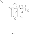
- FIG. 3 is a side view showing an interface between the adapter 200 and the power outlet 300.
- the adapter 200 can include one or more prongs 205 on a rear surface 206 of the adapter 200 that are insertable into at least one socket 302 in the power outlet 300 to connect the adapter 200 to the power outlet 300.
- the adapter 200 When the adapter 200 is connected to the power outlet 300, the adapter 200 substantially covers a faceplate 304 of the power outlet 300, and is substantially parallel with a wall 15 into which the power outlet 300 is mounted.
- the adapter 200 has at least one socket 202 on a front surface 208 that can receive the one or more prongs 106 of the plug 104. When connected to the power outlet 300, the adapter 200 can provide an electrical connection between the plug 104 and the power outlet 300.
- the adapter 200 is shown as having two sockets 202 arranged in a vertical configuration.
- the adapter 200 can have alternative socket configurations such that the adapter 200 can have a single socket configuration, or multiple sockets arranged in vertical and/or horizontal configurations.
- the adapter 200 includes second antennas 204 that are embedded within the front surface 208 of the adapter 200.
- the second antenna 204 is spaced or offset from the front surface 208 of the adapter 200 in a range from about 3 to about 4 cm. In some examples, the second antenna 204 is spaced or offset from the front surface 208 of the adapter 200 by less than 3 cm.
- Each second antenna 204 has a shape that surrounds a socket 202 in the adapter 200.
- the shape of each second antenna 204 is an ellipse (e.g., circle, oval, coil etc.) that surrounds a socket 202.
- the shape of each second antenna 204 is a rectangle or square or other shape that can surround a socket 202.
- a single second antenna 204 can surround multiple sockets 202.
- it is contemplated that the second antenna 204 can be positioned in other areas of the socket 202.
- the adapter 200 includes two second antennas 204 (each second antenna 204 surrounds a socket 202).
- the adapter 200 can have a single second antenna 204, or can have more than two second antennas 204 as may be needed and/or desired for a particular application.
- the first antenna 108 is a passive antenna that is part of a circuit that is not wired to a power source.
- the first antenna 108 can be a passive near-field communication (NFC) antenna such that the first antenna 108 is a "target" antenna meaning that the first antenna 108 remains in a sleep state unless powered by a radio-frequency (RF) field actively generated by another antenna.
- the first antenna 108 can have a simple form factor such as an unpowered tag or sticker (e.g., having a coil shape that surrounds the one or more prongs 106 of the plug 104). The coil shape of the first antenna 108 can reduce and/or eliminate the electromagnetic interference from one or more conductors that run in the power cord 102.
- each second antenna 204 is an active NFC antenna that can power the first antenna 108.
- Each second antenna 204 can be part of a circuit that actively generates an RF field using power drawn from the power outlet 300 when the adapter 200 is electrically connected to the power outlet 300.
- the RF field generated by each second antenna 204 can power the first antenna 108 when the first antenna 108 is spaced within a predetermined distance of a second antenna 204.
- the first antenna 108 is powered when spaced about 4 cm or less from a second antenna 204. This can occur when the one or more prongs 106 of the plug 104 are received in a socket 202 of the adapter 200 (and hence the first antenna 108 is proximate a second antenna 204).
- the passive first antenna transfers the device ID to the second antenna 204.
- the first antenna 108 is an active NFC antenna such that the first antenna 108 is part of a separate circuit 112 that actively generates an RF field using the first antenna 108 so that the first antenna 108 and a second antenna 204 of the adapter 200 can wirelessly communicate with one another according to a peer-to-peer protocol.
- the separate circuit 112 of the first antenna 108 can be located in the device 100 (e.g., not in the plug 104), and the separate circuit 112 can be connected to the first antenna 108 via a wire that runs in the power cord 102.
- the separate circuit 112 of the first antenna 108 can be powered by the power outlet 300 via the wire in the power cord 102 when the one or more prongs 106 are inserted in a socket 202 of the adapter 200, and the adapter 200 is electrically connected to the power outlet 300.
- the adapter 200 includes a controller 212 connected to a communication module 214 and to each second antenna 204.
- the controller 212 is a microprocessor that includes an internal memory.
- the internal memory of the controller 212 can store data such as a power outlet ID that can be used to identify the power outlet 300 to which the adapter 200 is connected.
- the internal memory of the controller 212 contains the data as read-only data.
- the data stored on the internal memory of the controller 212 is rewriteable.
- the internal memory of the controller 212 can store other data in addition to the power outlet ID.
- the controller 212 receives and can store the device ID from a second antenna 204, and uses the communication module 214 to wirelessly transfer the device ID and the power outlet ID to the network 20 (see FIG. 1 ). In some alternative examples, the controller 212 can transfer the power outlet ID and the device ID to the network 20 via a wired connection.
- network 20 transmits the device ID and the power outlet ID to the computer server 30.
- the network 20 transmits the device ID and the power outlet ID wirelessly to the computer server 30.
- the network 20 transmits the device ID and the power outlet ID to the computer server 30 via a wired connection.
- the computer server 30 may include at least one processor 34, a memory 36, and a communication module 32.
- the communication module 32 can receive the device ID and the power outlet ID from the network 20.
- the processor 34 uses the device ID and the power outlet ID to determine the location of the device 100 within a room of the building.
- the processor 34 can use a look-up table stored in the memory 36 that matches the power outlet ID to a particular room or a portion within a particular room of the building, such as a room or a portion of a room within the healthcare facility 2 shown in FIG. 1 .
- the processor 34 can determine that the device 100 is located within that particular room of the building. Also, the lookup table may have information that identifies a particular patient assigned to the device 100. Therefore, the processor 34 can identify the location of a patient within the healthcare facility 2 using the power outlet ID and the device ID.
- the memory 36 may comprise, but is not limited to, volatile storage (e.g., random access memory), non-volatile storage (e.g., read-only memory), flash memory, or any combination of such memories.
- the memory 36 may include an operating system and one or more program modules suitable for running software applications.
- the operating system for example, may be suitable for controlling the operation of the computer server 30.
- embodiments of the disclosure may be practiced in conjunction with a graphics library, other operating systems, or any other application program and is not limited to any particular application or system.
- the computer server 30 may have additional features or functionality.
- the computer server 30 may also include additional data storage devices (removable and/or non-removable) such as, for example, magnetic disks, optical disks, or tape.
- the computer server 30 can include, or be connected to, a display 38 that displays the location of the device 100.
- the display 408 can display the location of the device 100 as a room number. In other examples, the display 408 can display the location of the device 100 as a point within a map of the building.
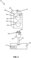
- FIG. 4 is a schematic diagram of an alternative system 60 that can identify a location of a device 500 within a room of a building.
- the device 500 can be a hospital bed within a large building such as a hospital that can have multiple floors and rooms.
- the device 500 includes a power cord 502 having at one end a plug 504 and one or more prongs 506 that extend from the plug 504.
- the one or more prongs 506 are configured to couple the plug 504 to a socket 602 of a power outlet 600.
- the one or more prongs 506 draw electrical power from the power outlet 600 for powering the device 500.
- the device 500 is a hospital bed.
- the prongs 506 draw electrical power from the power outlet 600 for powering the hospital bed, including such features as height adjustment, entertainment options like television control, and/or emergency alert options like a call button that can be actuated by the patient to summon assistance from a caregiver.
- the plug 504 carries a first antenna 508.
- the first antenna 508 has a shape that surrounds the one or more prongs 506 of the plug 504.
- the shape of the first antenna 508 is an ellipse (e.g., circle, oval, coil etc.) that surrounds the one or more prongs 506.
- the shape of the first antenna 508 is a rectangle or square or other shape that can surround the one or more prongs 506.
- it is contemplated that the first antenna 508 can be positioned in other areas of the plug 504.
- the first antenna 508 is embedded in the plug 504 such that the first antenna 508 is spaced or offset from an exterior surface of the plug 504 in a range from about 3 to about 4 cm. In some examples, the first antenna 508 is embedded in the plug 504 such that the first antenna 508 is spaced or offset from an exterior surface of the plug 504 by less than 3 cm.
- the plug 504 can have a memory 510 connected to the first antenna 508 and/or embedded within the first antenna 508.
- the memory 510 can store data such as a device ID that can be used to identify the device 500.
- the memory 510 contains the data as read-only data.
- the data stored on the memory 510 is rewriteable.
- the memory 510 can store other data in addition to the device ID.
- the power outlet 600 includes a faceplate 608 that can replace a standard faceplate of the power outlet.
- the faceplate 608 of the power outlet 600 includes several features (described in more detail below) that can be used to identify the location of the device 500 when connected to the power outlet 600.
- FIG. 5 is a side view showing an interface between the plug 504 and the power outlet 600.
- the one or more prongs 506 couple the plug 504 to a socket 602 of a power outlet 600 such that the plug 504 abuts and/or faces within close proximity the faceplate 608 of the power outlet 600.
- the faceplate 608 is substantially parallel to a wall 115 of a room and is substantially flush with the wall 115.
- the power outlet 600 has two sockets 602 arranged in a vertical configuration.
- the power outlet 600 can have alternative socket configurations such that the power outlet 600 can have a single socket configuration, or multiple sockets arranged in vertical and/or horizontal configurations.
- FIG. 6 is a rear view of the faceplate 608.
- the faceplate 608 can include one or more openings 616 that surround the sockets 602 of the power outlet 600 when the faceplate 608 is mounted to the power outlet 600.
- the shape and configuration of the openings 616 in the faceplate 608 can be modified depending on the configuration of the sockets 602 in the power outlet 600.
- faceplate 608 can have a single opening or multiple openings (e.g., two openings), and the openings of the faceplate 608 can be arranged in a vertical and/or horizontal configuration depending on the configuration of the sockets 602.
- the faceplate 608 includes second antennas 604 embedded within a front surface of the faceplate 608.
- Each second antenna 604 has a shape that surrounds an opening 616 (and hence a socket 602 of the power outlet 600 when the faceplate 608 is mounted to the power outlet 600).
- the shape of each second antenna 604 is an ellipse (e.g., circle, oval, coil etc.) that surrounds the one or more openings 616.
- the shape of each second antenna 604 is a rectangle or square or other shape that can surround the one or more openings 616.
- a single second antenna 604 can surround multiple openings 616.
- it is contemplated that the second antenna 604 can be positioned in other areas of the faceplate 608.
- the faceplate 608 includes two second antennas 604 (each second antenna 604 surrounding an opening 616).
- the faceplate 608 can have a single second antenna 604, or can have more than two second antennas 604 as needed and/or desired for a particular application.
- the first antenna 508 is a passive near-field communication (NFC) antenna such that the first antenna 508 is a "target" antenna meaning that the first antenna 508 remains in a sleep state unless powered by a radio-frequency (RF) field actively generated by another antenna.
- the first antenna 508 can have a simple form factor such as an unpowered tag or sticker (e.g., having a coil shape that surrounds the one or more prongs 506 of the plug 504).
- the coil shape of the first antenna 508 can reduce and/or eliminate the electromagnetic interference from one or more conductors that run in the power cord 502.
- each second antenna 604 is an active NFC antenna that can power the first antenna 508.
- Each second antenna 604 can be part of a circuit that actively generates an RF field using power drawn from the power outlet 600.
- the RF field generated by each second antenna 604 can power the first antenna 508 when the first antenna 508 is spaced within a predetermined distance of a second antenna 604.
- the first antenna 508 is powered when spaced 4 cm or less from a second antenna 604. This can occur when the one or more prongs 506 of the plug 504 are received in a socket 602 of the power outlet 600 (and hence the first antenna 508 is proximate a second antenna 604).
- the first antenna 508 transfers the device ID to the second antenna 604.
- the first antenna 508 is an active NFC antenna such that the first antenna 508 is part of a separate circuit 512 that actively generates an RF field using the first antenna 508 so that the first antenna 508 and a second antenna 604 of the power outlet 600 can wirelessly communicate with one another according to a peer-to-peer protocol.
- the separate circuit 512 can be located in the device 500 (e.g., not in the plug 504), and the separate circuit 512 can be connected to the first antenna 508 via a wire that runs in the power cord 502.
- the separate circuit 512 of the first antenna 508 can be powered by the power outlet 600 via the wire in the power cord 102 when the one or more prongs 106 are inserted in a socket 602 of the power outlet 600.
- the faceplate 608 includes a controller 612 connected to a communication module 614 and to each second antenna 604.
- the controller 612 is a microprocessor having an internal memory.
- the internal memory of the controller 612 can store data such as a power outlet ID that can be used to identify the power outlet 600.
- the internal memory of the controller 612 contains the data as read-only data.
- the data stored on the internal memory of the controller 612 can be rewriteable.
- the internal memory of the controller 612 can store other data in addition to the power outlet ID.
- the controller 612 can receive and store the device ID from a second antenna 604, and can use the communication module 614 to wirelessly transfer the device ID and the power outlet ID to the network 20 (see FIG. 1 ). In some alternative examples, the controller 612 can transfer the power outlet ID and the device ID to the network 20 via a wired connection.
- the network 20 can transfer the device ID and the power outlet ID to the computer server 30. Thereafter, the computer server 30 can use the device ID and power outlet ID data to determine the location of the device 500 within a building, such as the healthcare facility 2 (see FIG. 1 ). For example, the computer server 30 can use a lookup table to determine the location of the device 500 using the device ID and the power outlet ID, and can also identify the location of a patient associated with the device 500 using the lookup table.
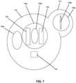
- FIG. 7 is a front view of a plug 700 for a medical device showing alternative shapes and locations for an antenna carried by the plug 700. These shapes and locations for the antenna can be implemented separately (i.e., a single antenna can be shaped and located in any of the positions shown) and/or multiple antenna can be provided on the plug 700.
- an antenna 708a has a coil shape and is located to surround one or more prongs 706 on the plug 700.
- the antenna 708a is similar to the first antenna 108 of the plug 104 described above, in that the antenna 708a is positioned to surround prongs 706 of the plug 700.
- Another alternative antenna 708b has a coil shape and is located within a boundary at least partially defined by the prongs 706. In this example, the antenna 708b is completely bounded by the prongs 706 on at least two sides.
- Another alternative antenna 708c has a coil shape and is located adjacent to the one or more prongs 706, but the antenna 708c does not surround the one or more prongs (unlike the antenna 708a), and the antenna 708c is not within a boundary defined by the one or more prongs 706 (unlike the antenna 708b).
- the antennas 708a, 708b, and 708c on the plug 700 can have shapes such as an ellipse, circle, oval, rectangle, square, and the like.
- a corresponding antenna (not shown) on a front surface of an adapter (such as the adapter 200 in FIGS. 2 and 3 ) or a faceplate of a power outlet (such as the power outlet 600 FIGS. 4 and 5 ) can have a shape and location that corresponds to the shape and location of an antenna 708a, 708b, and 708c so that when the plug 700 is inserted into the adapter or power outlet, the antenna 708a, 708b, and 708c on the plug 700 aligns with the corresponding antenna.
- the plug 700 can have a form factor that includes a structure 716 that projects laterally from the long axis of the plug 700. As shown in FIG. 7 , the structure 716 has an ear-like appearance. In this example, an antenna 708d having a linear shape that is parallel with the long axis of the plug 700 can be located in the structure 716. In yet another example, an antenna 708e having a coil shape can be located in the structure 716. In other examples, the antennas 708d and 708e can have shapes such as an ellipse, circle, oval, rectangle, square, and the like. Also, a front surface of an adapter (such as the adapter 200 in FIGS.
- a faceplate of a power outlet can have a corresponding ear-like structure (not shown) that includes a corresponding antenna such that when the plug 700 is inserted into the adapter or power outlet, the antenna 708d and 708e in the structure 716 aligns with the corresponding antenna of the adapter or power outlet.
- the antenna is incorporated into the plug of the medical device.
- the antenna can be incorporated as part of an adapter into which the plug of the medical device is inserted.
- This adapter can include the unique identifier for the medical device, as well as prongs to be connected to a power outlet and the antenna to communicate therewith as described herein. Other configurations are possible.
- a passive sticker or faceplate including the antenna can be applied on the wall outlet side or a passthrough adapter that has memory and is passive.
- the plug for the medical device can include the reader, and the processor, and memory.
- the wireless radio can be provided on the bedside and is used to broadcast the identification information to an access point and/or a central server.
Landscapes
- Engineering & Computer Science (AREA)
- Computer Networks & Wireless Communication (AREA)
- Signal Processing (AREA)
- Details Of Connecting Devices For Male And Female Coupling (AREA)
Description
- The physical location of a device can be an important piece of information. In the healthcare context, medical devices, such as hospital beds, can include special features both for the comfort and well-being of a patient. Identifying the location of a hospital bed with the healthcare facility can be important, particularly when a patient is in need of attention.
-
US 2013/135160 A1 provides an apparatus for providing data communication and power to a device located in a room having a power outlet. The power outlet may be a standard AC outlet, for example. The apparatus includes a cable extending from the device and having a plug comprising a plug body. Prongs extend from the plug body and couple to the power outlet to receive power. A first near field communication antenna is carried by the plug body. A communication module has a second near field communication antenna and is located in the room in proximity to the plug. At least one of the first near field communication antenna and the second near field communication antenna communicates data wirelessly to the other of the first near field communication antenna and the second near field communication antenna. Additional relevant prior art isUS 2015/081335 A1 andUS 2014/117083 A1 . - The invention is set out in the appended set of claims.
- One aspect relates to a system for identifying a location of a device. The system comprises a first antenna associated with a plug of the device. The first antenna has a coil shape that surrounds one or more prongs of the plug, and the plug has a memory that stores a device ID. The system comprises a second antenna that receives the device ID from the first antenna when the plug is coupled to a power outlet. The system further comprises a controller that receives the device ID from the second antenna, and that uses a communication module to wirelessly transfer the device ID and a power outlet ID to a computer server. The computer server has a processor and a memory, wherein the memory stores instructions that, when executed by the processor, cause the computer server to use the device ID and the power outlet ID to determine the location of the device within a building.
- Another aspect relates to a hospital bed that comprises a power cord having at one end a plug and one or more prongs extending from the plug that are configured to couple the plug to a power outlet. The hospital bed further comprises a first antenna carried by the plug. The first antenna has a coil shape that surrounds the one or more prongs of the plug. The first antenna is a near-field communication antenna having a memory that stores a device ID for identifying the hospital bed, transferrable to a second antenna when the first antenna is proximate the second antenna, the device ID is usable by a computer server to determine the location of the hospital bed within a building.
- The details of one or more techniques are set forth in the accompanying drawings and the description below. Other features, objects, and advantages of these techniques will be apparent from the description, drawings, and claims.
-
FIG. 1 is a schematic diagram of a healthcare facility having multiple rooms and hospital beds located within each room. -
FIG. 2 is schematic diagram of a system that can identify a location of a device. -
FIG. 3 is a side view showing an interface between a plug, an adapter, and a power outlet in the system ofFIG. 2 . -
FIG. 4 is a schematic diagram of another system that can identify a location of a device. -
FIG. 5 is a side view showing an interface between a plug and a power outlet in the system ofFIG. 4 . -
FIG. 6 is a rear view of a faceplate of the power outlet in the system ofFIG. 4 . -
FIG. 7 is a front view of a plug showing alternative shapes and locations for an antenna carried by the plug. - The present application is directed to the determination of the physical location of a device connected to a power outlet within a building. In the example embodiments described herein, the device is a medical device, such as a hospital bed or patient monitoring device, positioned within a healthcare facility having multiple floors and rooms making it difficult to locate a particular medical device that may or may not be associated with a patient of the healthcare facility. Although the example embodiments are described in the context of a healthcare facility and a hospital bed, the principles of the present application are applicable to other types of scenarios and devices, such as medical diagnostic devices and patient lift devices, as well.
- Examples of systems that can assist in locating medical devices, such as hospital beds, within a healthcare facility are provided in
U.S. Patent Nos. 7,399,205 ;9,466,877 9,830,424 -
FIG. 1 is a schematic diagram of ahealthcare facility 2 havingmultiple rooms hospital beds 12 located within each room. Each room within thehealthcare facility 2 can have one ormore power outlets 14. As shown inFIG. 1 , eachhospital bed 12 is located next to apower outlet 14 so that apower cord 16 from eachhospital bed 12 can be plugged into apower outlet 14 for powering the bed. - As also shown in
FIG. 1 , eachpower outlet 14 is connected to anetwork 20 so that eachpower outlet 14 can transfer data to the network 20 (only twopower outlets 14 are schematically shown connected to thenetwork 20 for ease of illustration). In some examples, eachpower outlet 14 transfers data wirelessly to thenetwork 20. In other examples, eachpower outlet 14 transfers data to thenetwork 20 via a wired connection. As will be explained in more detail, thenetwork 20 is connected to acomputer server 30 that can use the data transferred from apower outlet 14 to determine a location of aparticular hospital bed 12 within thehealthcare facility 2. -
FIG. 2 is a schematic diagram of asystem 50 that can identify a location of adevice 100. As shown inFIG. 2 , thedevice 100 includes apower cord 102 having at one end aplug 104 and one ormore prongs 106 that extend from theplug 104. Theprongs 106 are configured to couple theplug 104 to asocket 302 of apower outlet 300. When coupled to thesocket 302, theprongs 106 draw electrical power from thepower outlet 300 for powering the device 100.In the example shown, thedevice 100 is a hospital bed. Theprongs 106 draw electrical power from thepower outlet 300 for powering the hospital bed, including such features as height adjustment, entertainment options like television control, and/or emergency alert options like a call button that can be actuated by the patient to summon assistance from a caregiver. - In the example shown in
FIG. 2 , thepower outlet 300 has twosockets 302 arranged in a vertical configuration. In other examples, thepower outlet 300 can have alternative socket configurations such that thepower outlet 300 can have a single socket configuration, or multiple sockets arranged in vertical and/or horizontal configurations. - The
plug 104 carries afirst antenna 108. Thefirst antenna 108 has a coil shape that surrounds the one ormore prongs 106 of theplug 104. In some examples, the shape of thefirst antenna 108 is an ellipse (e.g., circle, oval, coil etc.) that surrounds the one ormore prongs 106. In other examples, the shape of thefirst antenna 108 is a rectangle, square, or other shape that can surround the one ormore prongs 106. In some alternative examples, it is contemplated that thefirst antenna 108 can be positioned in other areas of theplug 104. - In some examples, the
first antenna 108 is embedded in theplug 104 such that thefirst antenna 108 is spaced or offset from an exterior surface of theplug 104 in a range from about 3 to about 4 cm. In some examples, thefirst antenna 108 is embedded in theplug 104 such that thefirst antenna 108 is spaced or offset from an exterior surface of theplug 104 by less than 3 cm. - The
plug 104 has amemory 110 connected to thefirst antenna 108 and/or embedded within thefirst antenna 108. Thememory 110 stores data. The data includes a device ID that can be used to identify thedevice 100. In some examples, thememory 110 contains the data as read-only data. In some examples, the data stored on thememory 110 is rewriteable. In some examples, thememory 110 can store other data in addition to the device ID. - In the example shown in
FIG. 2 , thesystem 50 includes anadapter 200 that can connect to thepower outlet 300.FIG. 3 is a side view showing an interface between theadapter 200 and thepower outlet 300. As shown inFIGS. 2 and3 , theadapter 200 can include one ormore prongs 205 on arear surface 206 of theadapter 200 that are insertable into at least onesocket 302 in thepower outlet 300 to connect theadapter 200 to thepower outlet 300. When theadapter 200 is connected to thepower outlet 300, theadapter 200 substantially covers afaceplate 304 of thepower outlet 300, and is substantially parallel with awall 15 into which thepower outlet 300 is mounted. Theadapter 200 has at least onesocket 202 on afront surface 208 that can receive the one ormore prongs 106 of theplug 104. When connected to thepower outlet 300, theadapter 200 can provide an electrical connection between theplug 104 and thepower outlet 300. - In the example shown in
FIG. 2 , theadapter 200 is shown as having twosockets 202 arranged in a vertical configuration. In other examples, theadapter 200 can have alternative socket configurations such that theadapter 200 can have a single socket configuration, or multiple sockets arranged in vertical and/or horizontal configurations. - As shown in
FIG. 1 , theadapter 200 includessecond antennas 204 that are embedded within thefront surface 208 of theadapter 200. In some examples, thesecond antenna 204 is spaced or offset from thefront surface 208 of theadapter 200 in a range from about 3 to about 4 cm. In some examples, thesecond antenna 204 is spaced or offset from thefront surface 208 of theadapter 200 by less than 3 cm. - Each
second antenna 204 has a shape that surrounds asocket 202 in theadapter 200. In some examples, the shape of eachsecond antenna 204 is an ellipse (e.g., circle, oval, coil etc.) that surrounds asocket 202. In other examples, the shape of eachsecond antenna 204 is a rectangle or square or other shape that can surround asocket 202. In some examples, a singlesecond antenna 204 can surroundmultiple sockets 202. In some examples, it is contemplated that thesecond antenna 204 can be positioned in other areas of thesocket 202. - In the example shown in
FIG. 2 , theadapter 200 includes two second antennas 204 (eachsecond antenna 204 surrounds a socket 202). In other examples, theadapter 200 can have a singlesecond antenna 204, or can have more than twosecond antennas 204 as may be needed and/or desired for a particular application. - In some examples, the
first antenna 108 is a passive antenna that is part of a circuit that is not wired to a power source. As an example, thefirst antenna 108 can be a passive near-field communication (NFC) antenna such that thefirst antenna 108 is a "target" antenna meaning that thefirst antenna 108 remains in a sleep state unless powered by a radio-frequency (RF) field actively generated by another antenna. In certain examples, thefirst antenna 108 can have a simple form factor such as an unpowered tag or sticker (e.g., having a coil shape that surrounds the one ormore prongs 106 of the plug 104). The coil shape of thefirst antenna 108 can reduce and/or eliminate the electromagnetic interference from one or more conductors that run in thepower cord 102. - In some examples, each
second antenna 204 is an active NFC antenna that can power thefirst antenna 108. Eachsecond antenna 204 can be part of a circuit that actively generates an RF field using power drawn from thepower outlet 300 when theadapter 200 is electrically connected to thepower outlet 300. The RF field generated by eachsecond antenna 204 can power thefirst antenna 108 when thefirst antenna 108 is spaced within a predetermined distance of asecond antenna 204. In certain examples, thefirst antenna 108 is powered when spaced about 4 cm or less from asecond antenna 204. This can occur when the one ormore prongs 106 of theplug 104 are received in asocket 202 of the adapter 200 (and hence thefirst antenna 108 is proximate a second antenna 204). When thefirst antenna 108 is powered by asecond antenna 204, the passive first antenna transfers the device ID to thesecond antenna 204. - In alternative examples, the
first antenna 108 is an active NFC antenna such that thefirst antenna 108 is part of aseparate circuit 112 that actively generates an RF field using thefirst antenna 108 so that thefirst antenna 108 and asecond antenna 204 of theadapter 200 can wirelessly communicate with one another according to a peer-to-peer protocol. In such examples, theseparate circuit 112 of thefirst antenna 108 can be located in the device 100 (e.g., not in the plug 104), and theseparate circuit 112 can be connected to thefirst antenna 108 via a wire that runs in thepower cord 102. Theseparate circuit 112 of thefirst antenna 108 can be powered by thepower outlet 300 via the wire in thepower cord 102 when the one ormore prongs 106 are inserted in asocket 202 of theadapter 200, and theadapter 200 is electrically connected to thepower outlet 300. - As shown in
FIG. 2 , theadapter 200 includes acontroller 212 connected to acommunication module 214 and to eachsecond antenna 204. In certain examples, thecontroller 212 is a microprocessor that includes an internal memory. In some examples, the internal memory of thecontroller 212 can store data such as a power outlet ID that can be used to identify thepower outlet 300 to which theadapter 200 is connected. In some examples, the internal memory of thecontroller 212 contains the data as read-only data. In some examples, the data stored on the internal memory of thecontroller 212 is rewriteable. In some examples, the internal memory of thecontroller 212 can store other data in addition to the power outlet ID. - In some examples, the
controller 212 receives and can store the device ID from asecond antenna 204, and uses thecommunication module 214 to wirelessly transfer the device ID and the power outlet ID to the network 20 (seeFIG. 1 ). In some alternative examples, thecontroller 212 can transfer the power outlet ID and the device ID to thenetwork 20 via a wired connection. - Referring back to
FIG. 1 ,network 20 transmits the device ID and the power outlet ID to thecomputer server 30. In some examples, thenetwork 20 transmits the device ID and the power outlet ID wirelessly to thecomputer server 30. In other examples, thenetwork 20 transmits the device ID and the power outlet ID to thecomputer server 30 via a wired connection. - As shown in
FIG. 1 , the physical components (i.e., hardware) of thecomputer server 30 with which embodiments of the disclosure may be practiced are illustrated. In a basic configuration, thecomputer server 30 may include at least oneprocessor 34, amemory 36, and acommunication module 32. Thecommunication module 32 can receive the device ID and the power outlet ID from thenetwork 20. Theprocessor 34 uses the device ID and the power outlet ID to determine the location of thedevice 100 within a room of the building. In some examples, theprocessor 34 can use a look-up table stored in thememory 36 that matches the power outlet ID to a particular room or a portion within a particular room of the building, such as a room or a portion of a room within thehealthcare facility 2 shown inFIG. 1 . Using the device ID, theprocessor 34 can determine that thedevice 100 is located within that particular room of the building. Also, the lookup table may have information that identifies a particular patient assigned to thedevice 100. Therefore, theprocessor 34 can identify the location of a patient within thehealthcare facility 2 using the power outlet ID and the device ID. - Depending on the configuration and type of computer server, the
memory 36 may comprise, but is not limited to, volatile storage (e.g., random access memory), non-volatile storage (e.g., read-only memory), flash memory, or any combination of such memories. Thememory 36 may include an operating system and one or more program modules suitable for running software applications. The operating system, for example, may be suitable for controlling the operation of thecomputer server 30. Furthermore, embodiments of the disclosure may be practiced in conjunction with a graphics library, other operating systems, or any other application program and is not limited to any particular application or system. Thecomputer server 30 may have additional features or functionality. For example, thecomputer server 30 may also include additional data storage devices (removable and/or non-removable) such as, for example, magnetic disks, optical disks, or tape. - The
computer server 30 can include, or be connected to, adisplay 38 that displays the location of thedevice 100. In some examples, the display 408 can display the location of thedevice 100 as a room number. In other examples, the display 408 can display the location of thedevice 100 as a point within a map of the building. -
FIG. 4 is a schematic diagram of analternative system 60 that can identify a location of adevice 500 within a room of a building. Like in the first example embodiment described above, thedevice 500 can be a hospital bed within a large building such as a hospital that can have multiple floors and rooms. - The
device 500 includes apower cord 502 having at one end aplug 504 and one ormore prongs 506 that extend from theplug 504. The one ormore prongs 506 are configured to couple theplug 504 to asocket 602 of apower outlet 600. When coupled to thesocket 602, the one ormore prongs 506 draw electrical power from thepower outlet 600 for powering the device 500.In the example shown, thedevice 500 is a hospital bed. Theprongs 506 draw electrical power from thepower outlet 600 for powering the hospital bed, including such features as height adjustment, entertainment options like television control, and/or emergency alert options like a call button that can be actuated by the patient to summon assistance from a caregiver. - The
plug 504 carries afirst antenna 508. Thefirst antenna 508 has a shape that surrounds the one ormore prongs 506 of theplug 504. In some examples, the shape of thefirst antenna 508 is an ellipse (e.g., circle, oval, coil etc.) that surrounds the one ormore prongs 506. In other examples, the shape of thefirst antenna 508 is a rectangle or square or other shape that can surround the one ormore prongs 506. In some examples, it is contemplated that thefirst antenna 508 can be positioned in other areas of theplug 504. - In some examples, the
first antenna 508 is embedded in theplug 504 such that thefirst antenna 508 is spaced or offset from an exterior surface of theplug 504 in a range from about 3 to about 4 cm. In some examples, thefirst antenna 508 is embedded in theplug 504 such that thefirst antenna 508 is spaced or offset from an exterior surface of theplug 504 by less than 3 cm. - The
plug 504 can have amemory 510 connected to thefirst antenna 508 and/or embedded within thefirst antenna 508. Thememory 510 can store data such as a device ID that can be used to identify thedevice 500. In some examples, thememory 510 contains the data as read-only data. In some examples, the data stored on thememory 510 is rewriteable. In some examples, thememory 510 can store other data in addition to the device ID. - In the example shown in
FIG. 4 , thepower outlet 600 includes afaceplate 608 that can replace a standard faceplate of the power outlet. Thefaceplate 608 of thepower outlet 600 includes several features (described in more detail below) that can be used to identify the location of thedevice 500 when connected to thepower outlet 600. -
FIG. 5 is a side view showing an interface between theplug 504 and thepower outlet 600. As shown inFIGS. 4 and5 , the one ormore prongs 506 couple theplug 504 to asocket 602 of apower outlet 600 such that theplug 504 abuts and/or faces within close proximity thefaceplate 608 of thepower outlet 600. As shown inFIG. 5 , thefaceplate 608 is substantially parallel to awall 115 of a room and is substantially flush with thewall 115. - As shown in the example of
FIG. 2 , thepower outlet 600 has twosockets 602 arranged in a vertical configuration. In other examples, thepower outlet 600 can have alternative socket configurations such that thepower outlet 600 can have a single socket configuration, or multiple sockets arranged in vertical and/or horizontal configurations. -
FIG. 6 is a rear view of thefaceplate 608. As shown inFIG. 6 , thefaceplate 608 can include one ormore openings 616 that surround thesockets 602 of thepower outlet 600 when thefaceplate 608 is mounted to thepower outlet 600. The shape and configuration of theopenings 616 in thefaceplate 608 can be modified depending on the configuration of thesockets 602 in thepower outlet 600. For example,faceplate 608 can have a single opening or multiple openings (e.g., two openings), and the openings of thefaceplate 608 can be arranged in a vertical and/or horizontal configuration depending on the configuration of thesockets 602. - As shown in
FIGS. 4 and6 , thefaceplate 608 includessecond antennas 604 embedded within a front surface of thefaceplate 608. Eachsecond antenna 604 has a shape that surrounds an opening 616 (and hence asocket 602 of thepower outlet 600 when thefaceplate 608 is mounted to the power outlet 600). In some examples, the shape of eachsecond antenna 604 is an ellipse (e.g., circle, oval, coil etc.) that surrounds the one ormore openings 616. In other examples, the shape of eachsecond antenna 604 is a rectangle or square or other shape that can surround the one ormore openings 616. In some examples, a singlesecond antenna 604 can surroundmultiple openings 616. In some examples, it is contemplated that thesecond antenna 604 can be positioned in other areas of thefaceplate 608. - In the example shown in
FIGS. 2 and6 , thefaceplate 608 includes two second antennas 604 (eachsecond antenna 604 surrounding an opening 616). In other examples, thefaceplate 608 can have a singlesecond antenna 604, or can have more than twosecond antennas 604 as needed and/or desired for a particular application. - In some examples, the
first antenna 508 is a passive near-field communication (NFC) antenna such that thefirst antenna 508 is a "target" antenna meaning that thefirst antenna 508 remains in a sleep state unless powered by a radio-frequency (RF) field actively generated by another antenna. In certain examples, thefirst antenna 508 can have a simple form factor such as an unpowered tag or sticker (e.g., having a coil shape that surrounds the one ormore prongs 506 of the plug 504). The coil shape of thefirst antenna 508 can reduce and/or eliminate the electromagnetic interference from one or more conductors that run in thepower cord 502. - In some examples, each
second antenna 604 is an active NFC antenna that can power thefirst antenna 508. Eachsecond antenna 604 can be part of a circuit that actively generates an RF field using power drawn from thepower outlet 600. The RF field generated by eachsecond antenna 604 can power thefirst antenna 508 when thefirst antenna 508 is spaced within a predetermined distance of asecond antenna 604. In certain examples, thefirst antenna 508 is powered when spaced 4 cm or less from asecond antenna 604. This can occur when the one ormore prongs 506 of theplug 504 are received in asocket 602 of the power outlet 600 (and hence thefirst antenna 508 is proximate a second antenna 604). When thefirst antenna 508 is powered by asecond antenna 604, thefirst antenna 508 transfers the device ID to thesecond antenna 604. - In alternative examples, the
first antenna 508 is an active NFC antenna such that thefirst antenna 508 is part of aseparate circuit 512 that actively generates an RF field using thefirst antenna 508 so that thefirst antenna 508 and asecond antenna 604 of thepower outlet 600 can wirelessly communicate with one another according to a peer-to-peer protocol. In such examples, theseparate circuit 512 can be located in the device 500 (e.g., not in the plug 504), and theseparate circuit 512 can be connected to thefirst antenna 508 via a wire that runs in thepower cord 502. Theseparate circuit 512 of thefirst antenna 508 can be powered by thepower outlet 600 via the wire in thepower cord 102 when the one ormore prongs 106 are inserted in asocket 602 of thepower outlet 600. - As shown in
FIGS. 4 and6 , thefaceplate 608 includes acontroller 612 connected to acommunication module 614 and to eachsecond antenna 604. In certain examples, thecontroller 612 is a microprocessor having an internal memory. In some examples, the internal memory of thecontroller 612 can store data such as a power outlet ID that can be used to identify thepower outlet 600. In some examples, the internal memory of thecontroller 612 contains the data as read-only data. In some examples, the data stored on the internal memory of thecontroller 612 can be rewriteable. In some examples, the internal memory of thecontroller 612 can store other data in addition to the power outlet ID. - In some examples, the
controller 612 can receive and store the device ID from asecond antenna 604, and can use thecommunication module 614 to wirelessly transfer the device ID and the power outlet ID to the network 20 (seeFIG. 1 ).In some alternative examples, thecontroller 612 can transfer the power outlet ID and the device ID to thenetwork 20 via a wired connection. - As described above, the
network 20 can transfer the device ID and the power outlet ID to thecomputer server 30. Thereafter, thecomputer server 30 can use the device ID and power outlet ID data to determine the location of thedevice 500 within a building, such as the healthcare facility 2 (seeFIG. 1 ). For example, thecomputer server 30 can use a lookup table to determine the location of thedevice 500 using the device ID and the power outlet ID, and can also identify the location of a patient associated with thedevice 500 using the lookup table. -
FIG. 7 is a front view of aplug 700 for a medical device showing alternative shapes and locations for an antenna carried by theplug 700. These shapes and locations for the antenna can be implemented separately (i.e., a single antenna can be shaped and located in any of the positions shown) and/or multiple antenna can be provided on theplug 700. - As shown in
FIG. 7 , anantenna 708a has a coil shape and is located to surround one ormore prongs 706 on theplug 700. Theantenna 708a is similar to thefirst antenna 108 of theplug 104 described above, in that theantenna 708a is positioned to surroundprongs 706 of theplug 700. - Another
alternative antenna 708b has a coil shape and is located within a boundary at least partially defined by theprongs 706. In this example, theantenna 708b is completely bounded by theprongs 706 on at least two sides. - Another
alternative antenna 708c has a coil shape and is located adjacent to the one ormore prongs 706, but theantenna 708c does not surround the one or more prongs (unlike theantenna 708a), and theantenna 708c is not within a boundary defined by the one or more prongs 706 (unlike theantenna 708b). - In other examples, the
antennas plug 700 can have shapes such as an ellipse, circle, oval, rectangle, square, and the like. - In view of the alternative shapes and locations of the
antennas plug 700, a corresponding antenna (not shown) on a front surface of an adapter (such as theadapter 200 inFIGS. 2 and3 ) or a faceplate of a power outlet (such as thepower outlet 600FIGS. 4 and5 ) can have a shape and location that corresponds to the shape and location of anantenna plug 700 is inserted into the adapter or power outlet, theantenna plug 700 aligns with the corresponding antenna. - Alternatively, the
plug 700 can have a form factor that includes astructure 716 that projects laterally from the long axis of theplug 700. As shown inFIG. 7 , thestructure 716 has an ear-like appearance. In this example, anantenna 708d having a linear shape that is parallel with the long axis of theplug 700 can be located in thestructure 716. In yet another example, anantenna 708e having a coil shape can be located in thestructure 716. In other examples, theantennas adapter 200 inFIGS. 2 and3 ) or a faceplate of a power outlet (such as thepower outlet 600FIGS. 4 and5 ) can have a corresponding ear-like structure (not shown) that includes a corresponding antenna such that when theplug 700 is inserted into the adapter or power outlet, theantenna structure 716 aligns with the corresponding antenna of the adapter or power outlet. - In the examples shown, the antenna is incorporated into the plug of the medical device. In alternative embodiments, the antenna can be incorporated as part of an adapter into which the plug of the medical device is inserted. This adapter can include the unique identifier for the medical device, as well as prongs to be connected to a power outlet and the antenna to communicate therewith as described herein. Other configurations are possible.
- Although the configurations described herein include a passive antenna on the plug side and an active reader antenna on the outlet side, the sides could be switched. In this alternative, a passive sticker or faceplate including the antenna can be applied on the wall outlet side or a passthrough adapter that has memory and is passive. The plug for the medical device can include the reader, and the processor, and memory. The wireless radio can be provided on the bedside and is used to broadcast the identification information to an access point and/or a central server.
- The various embodiments described above are provided by way of illustration only and should not be construed to limiting.
Claims (13)
- A system (50) for identifying a location of a device (100), the system (50) comprising:a first antenna (108) associated with a plug (104, 700) of the device (100), the first antenna (108) having a coil shape that surrounds one or more prongs (106) of the plug (104, 700), and the plug (104, 700) having a memory (110) that stores a device ID;a second antenna (204) configured to receive the device ID from the first antenna (108) upon the plug (104, 700) being coupled to a power outlet (300, 600);a controller (212) configured to receive the device ID from the second antenna (204), the controller (212) being connected to a communication module (214) configured to wirelessly transfer the device ID and a power outlet ID identifying the power outlet (300, 600) to a computer server; anda computer server (30), wherein the computer server (30) includes a processor (34) and memory (36), wherein the memory (36) stores instructions that, when executed by the processor (34), cause the computer server (30) to use the device ID and the power outlet ID to determine the location of the device (100) within a building.
- The system (50) of claim 1, wherein the plug (104, 700) has a form factor that includes a structure (716) that projects laterally from the long axis of the plug (104, 700), and the first antenna (108) is located in the structure (716).
- The system (50) of claim 1 or 2, wherein the first antenna (108) is a part of a circuit (112) that is not wired to a power source, and the second antenna (204) is part of a circuit that actively powers the first antenna (108) to transfer the device ID to the second antenna (204).
- The system (50) of any of the preceding claims, wherein the first antenna (108) and the second antenna (204) are each connected to separate circuits that generate alternating radio frequency fields that allow the first antenna (108) and the second antenna (204) to wirelessly communicate with one another according to a peer-to-peer protocol.
- The system (50) of any of the preceding claims, wherein the second antenna (204) is embedded in an adapter (200) that connects to the power outlet (300, 600), the adapter (200) having at least one socket (202) that receives the one or more prongs (106) of the plug (104, 700), and the second antenna (204) having a coil shape that surrounds the at least one socket (202) in the adapter (200)
- The system (50) of claim 5, wherein the adapter (200) includes prongs that are insertable into at least one socket in the power outlet (300, 600), and the adapter (200) provides an electrical connection between the plug (104, 700) and the power outlet (300, 600).
- The system (50) of any of the preceding claims, wherein the first antenna (108) is configured to transfer the device ID to the second antenna (204) when spaced by 4 cm or less from the second antenna (204).
- The system (50) of any of the preceding claims, wherein the controller (212) and the communication module (214) are embedded in a front surface (208) of the adapter (200).
- The system (50) of any of the preceding claims, wherein the second antenna (204) is embedded in a faceplate (304, 608) of the power outlet (300, 600), the power outlet (300, 600) having at least one socket (302, 602) that receives the one or more prongs (106) of the plug (104, 700), and the faceplate (304, 608) having at least one opening (616) that surrounds the at least one socket (302, 602) of the power outlet (300, 600), wherein the second antenna (204) has a coil shape that surrounds the at least one opening (616) in the faceplate (304, 608), and/or wherein the controller (212) and the communication module (214) are embedded in a faceplate (304, 608) of the power outlet (300, 600).
- The system (50) of any of the preceding claims, wherein the device (100) is a hospital bed (12).
- A hospital bed (12) comprising:a power cord (16, 102) having at one end a plug (104, 700) and one or more prongs (106) extending from the plug (104, 700) that are configured to couple the plug (104, 700) to a power outlet (300, 600), anda first antenna (108) carried by the plug (104, 700), the first antenna (108) having a coil shape that surrounds the one or more prongs (106) of the plug (104, 700), wherein the first antenna (108) is a near-field communication antenna having a memory (110) that stores a device ID for identifying the hospital bed (12), transferrable to a second antenna (204) when the first antenna (108) is proximate the second antenna (204), the device ID and a power outlet ID identifying the power outlet (300, 600) being usable by a computer server (30) to determine the location of the hospital bed (12) within a building.
- The hospital bed (12) of claim 11, wherein the first antenna (108) is a passive near-field communication antenna that transfers the device ID to the second antenna (204) when spaced by 4 cm or less from the second antenna (204).
- The hospital bed (12) of claim 11 or 12, wherein the first antenna (108) is connected to a circuit that generates a radio frequency field that allows the first antenna (108) to wirelessly communicate with the second antenna (204) according to a peer-to-peer protocol.
Applications Claiming Priority (1)
| Application Number | Priority Date | Filing Date | Title |
|---|---|---|---|
| US201862754157P | 2018-11-01 | 2018-11-01 |
Publications (2)
| Publication Number | Publication Date |
|---|---|
| EP3648484A1 EP3648484A1 (en) | 2020-05-06 |
| EP3648484B1 true EP3648484B1 (en) | 2024-08-07 |
Family
ID=68426219
Family Applications (1)
| Application Number | Title | Priority Date | Filing Date |
|---|---|---|---|
| EP19206752.8A Active EP3648484B1 (en) | 2018-11-01 | 2019-11-01 | Identification of device location in healthcare facility |
Country Status (3)
| Country | Link |
|---|---|
| US (1) | US10958311B2 (en) |
| EP (1) | EP3648484B1 (en) |
| CN (1) | CN111148037A (en) |
Families Citing this family (5)
| Publication number | Priority date | Publication date | Assignee | Title |
|---|---|---|---|---|
| US11013418B2 (en) * | 2018-11-01 | 2021-05-25 | Hill-Rom Services, Inc. | Identification of device location in healthcare facility |
| US12042451B2 (en) | 2020-08-21 | 2024-07-23 | Hill-Rom Services, Inc. | Cable-free bed with wireless pillow speaker |
| US12186241B2 (en) | 2021-01-22 | 2025-01-07 | Hill-Rom Services, Inc. | Time-based wireless pairing between a medical device and a wall unit |
| US12279999B2 (en) | 2021-01-22 | 2025-04-22 | Hill-Rom Services, Inc. | Wireless configuration and authorization of a wall unit that pairs with a medical device |
| US12133314B2 (en) | 2021-04-13 | 2024-10-29 | Apple Inc. | Electronic devices having failsafe mechanisms with near field communications |
Citations (1)
| Publication number | Priority date | Publication date | Assignee | Title |
|---|---|---|---|---|
| US20140117083A1 (en) * | 2012-10-26 | 2014-05-01 | Elbex Video Ltd | Method and apparatus for identifying an electric load via rfid tag associated with a power plug |
Family Cites Families (15)
| Publication number | Priority date | Publication date | Assignee | Title |
|---|---|---|---|---|
| JP3820943B2 (en) | 2001-09-05 | 2006-09-13 | 富士通株式会社 | Electronic device adapter, electronic device management apparatus, and outlet for supplying power to the electronic device |
| WO2005022692A2 (en) | 2003-08-21 | 2005-03-10 | Hill-Rom Services, Inc. | Plug and receptacle having wired and wireless coupling |
| US9838836B2 (en) | 2005-03-29 | 2017-12-05 | Stryker Corporation | Patient support apparatus communication systems |
| AU2006230344A1 (en) | 2005-03-29 | 2006-10-05 | Stryker Canadian Management Inc. | Location detection system for a patient handling device |
| US20070271474A1 (en) | 2006-05-18 | 2007-11-22 | International Business Machines Corporation | System and method for disabling an electrical device |
| JP5274769B2 (en) | 2006-12-25 | 2013-08-28 | 株式会社東芝 | Equipment usage status management system |
| US8610562B2 (en) | 2010-02-01 | 2013-12-17 | Welch Allyn, Inc. | Automatic determination of location for ethernet devices |
| US9466877B2 (en) * | 2011-11-29 | 2016-10-11 | Hill-Rom Services, Inc. | Hospital bed having near field communication capability |
| US9830424B2 (en) * | 2013-09-18 | 2017-11-28 | Hill-Rom Services, Inc. | Bed/room/patient association systems and methods |
| CN204331416U (en) * | 2014-04-25 | 2015-05-13 | 象标信息技术(上海)有限公司 | Supply socket identifies the device of electric equipment automatically |
| US10085905B2 (en) | 2014-08-11 | 2018-10-02 | Stryker Corporation | Patient support apparatuses with wireless headwall communication |
| WO2016126112A1 (en) * | 2015-02-03 | 2016-08-11 | 주식회사 지오라인 | User authenticating electrical outlet or connector, power mediating module, and power consuming device |
| TWI521826B (en) | 2015-02-04 | 2016-02-11 | 碩天科技股份有限公司 | Power apparatus with outlet identification capability and outlet identification method of power apparatus |
| US9520043B1 (en) * | 2015-06-17 | 2016-12-13 | Lenovo Enterprise Solutions (Singapore) Pte. Ltd. | Identifying an outlet of a power distribution unit based on a power rating of an electronic device |
| US10540528B1 (en) * | 2017-12-11 | 2020-01-21 | Trexler Technologies, Inc. | Methods of making and using an identification tag system for use with an electromagnetic energy cable |
-
2019
- 2019-10-31 US US16/669,856 patent/US10958311B2/en active Active
- 2019-11-01 CN CN201911061804.1A patent/CN111148037A/en active Pending
- 2019-11-01 EP EP19206752.8A patent/EP3648484B1/en active Active
Patent Citations (1)
| Publication number | Priority date | Publication date | Assignee | Title |
|---|---|---|---|---|
| US20140117083A1 (en) * | 2012-10-26 | 2014-05-01 | Elbex Video Ltd | Method and apparatus for identifying an electric load via rfid tag associated with a power plug |
Also Published As
| Publication number | Publication date |
|---|---|
| US20200145057A1 (en) | 2020-05-07 |
| EP3648484A1 (en) | 2020-05-06 |
| CN111148037A (en) | 2020-05-12 |
| US10958311B2 (en) | 2021-03-23 |
Similar Documents
| Publication | Publication Date | Title |
|---|---|---|
| US10958311B2 (en) | Identification of device location in healthcare facility | |
| EP2599435B1 (en) | Hospital bed having near field communication capability | |
| US20250157638A1 (en) | Bed/room/patient association systems and methods | |
| US11013418B2 (en) | Identification of device location in healthcare facility | |
| EP4033793A1 (en) | Time-based wireless pairing between a medical device and a wall unit | |
| CN108012575A (en) | For data and/or the equipment being wirelessly transferred of power | |
| US20230337941A1 (en) | System for determining patient support apparatus and medical device location | |
| US12279999B2 (en) | Wireless configuration and authorization of a wall unit that pairs with a medical device | |
| JP2015097689A (en) | Power supply connection device for equipment management and medical equipment management system equipped with the same | |
| EP3962040A1 (en) | Cable-free bed with wireless pillow speaker | |
| US11642512B2 (en) | Managing the electric field exposure in a fully implanted LVAD system | |
| EP3861927B1 (en) | Identification of device location in healthcare facility | |
| US20240293277A1 (en) | System for locating patient support apparatuses | |
| WO2022251412A1 (en) | System for associating device data | |
| WO2023150202A2 (en) | Communication system for patient support apparatuses | |
| EP4135369A1 (en) | Wireless configuration and authorization of a wall unit that pairs with a medical device | |
| WO2023043875A1 (en) | Patient support apparatus communication and location system |
Legal Events
| Date | Code | Title | Description |
|---|---|---|---|
| PUAI | Public reference made under article 153(3) epc to a published international application that has entered the european phase |
Free format text: ORIGINAL CODE: 0009012 |
|
| STAA | Information on the status of an ep patent application or granted ep patent |
Free format text: STATUS: THE APPLICATION HAS BEEN PUBLISHED |
|
| AK | Designated contracting states |
Kind code of ref document: A1 Designated state(s): AL AT BE BG CH CY CZ DE DK EE ES FI FR GB GR HR HU IE IS IT LI LT LU LV MC MK MT NL NO PL PT RO RS SE SI SK SM TR |
|
| AX | Request for extension of the european patent |
Extension state: BA ME |
|
| STAA | Information on the status of an ep patent application or granted ep patent |
Free format text: STATUS: REQUEST FOR EXAMINATION WAS MADE |
|
| 17P | Request for examination filed |
Effective date: 20201105 |
|
| RBV | Designated contracting states (corrected) |
Designated state(s): AL AT BE BG CH CY CZ DE DK EE ES FI FR GB GR HR HU IE IS IT LI LT LU LV MC MK MT NL NO PL PT RO RS SE SI SK SM TR |
|
| STAA | Information on the status of an ep patent application or granted ep patent |
Free format text: STATUS: EXAMINATION IS IN PROGRESS |
|
| 17Q | First examination report despatched |
Effective date: 20220103 |
|
| GRAP | Despatch of communication of intention to grant a patent |
Free format text: ORIGINAL CODE: EPIDOSNIGR1 |
|
| STAA | Information on the status of an ep patent application or granted ep patent |
Free format text: STATUS: GRANT OF PATENT IS INTENDED |
|
| RIC1 | Information provided on ipc code assigned before grant |
Ipc: H04L 12/28 20060101ALN20240215BHEP Ipc: H01R 24/76 20110101ALN20240215BHEP Ipc: H01R 13/66 20060101ALN20240215BHEP Ipc: H01R 13/46 20060101ALN20240215BHEP Ipc: H04W 4/80 20180101ALI20240215BHEP Ipc: H04W 4/02 20180101AFI20240215BHEP |
|
| INTG | Intention to grant announced |
Effective date: 20240301 |
|
| GRAS | Grant fee paid |
Free format text: ORIGINAL CODE: EPIDOSNIGR3 |
|
| GRAA | (expected) grant |
Free format text: ORIGINAL CODE: 0009210 |
|
| STAA | Information on the status of an ep patent application or granted ep patent |
Free format text: STATUS: THE PATENT HAS BEEN GRANTED |
|
| AK | Designated contracting states |
Kind code of ref document: B1 Designated state(s): AL AT BE BG CH CY CZ DE DK EE ES FI FR GB GR HR HU IE IS IT LI LT LU LV MC MK MT NL NO PL PT RO RS SE SI SK SM TR |
|
| REG | Reference to a national code |
Ref country code: GB Ref legal event code: FG4D |
|
| REG | Reference to a national code |
Ref country code: CH Ref legal event code: EP |
|
| REG | Reference to a national code |
Ref country code: IE Ref legal event code: FG4D |
|
| REG | Reference to a national code |
Ref country code: DE Ref legal event code: R096 Ref document number: 602019056481 Country of ref document: DE |
|
| REG | Reference to a national code |
Ref country code: LT Ref legal event code: MG9D |
|
| REG | Reference to a national code |
Ref country code: NL Ref legal event code: MP Effective date: 20240807 |
|
| PG25 | Lapsed in a contracting state [announced via postgrant information from national office to epo] |
Ref country code: NO Free format text: LAPSE BECAUSE OF FAILURE TO SUBMIT A TRANSLATION OF THE DESCRIPTION OR TO PAY THE FEE WITHIN THE PRESCRIBED TIME-LIMIT Effective date: 20241107 |
|
| REG | Reference to a national code |
Ref country code: AT Ref legal event code: MK05 Ref document number: 1712217 Country of ref document: AT Kind code of ref document: T Effective date: 20240807 |
|
| PG25 | Lapsed in a contracting state [announced via postgrant information from national office to epo] |
Ref country code: NL Free format text: LAPSE BECAUSE OF FAILURE TO SUBMIT A TRANSLATION OF THE DESCRIPTION OR TO PAY THE FEE WITHIN THE PRESCRIBED TIME-LIMIT Effective date: 20240807 Ref country code: PT Free format text: LAPSE BECAUSE OF FAILURE TO SUBMIT A TRANSLATION OF THE DESCRIPTION OR TO PAY THE FEE WITHIN THE PRESCRIBED TIME-LIMIT Effective date: 20241209 Ref country code: PL Free format text: LAPSE BECAUSE OF FAILURE TO SUBMIT A TRANSLATION OF THE DESCRIPTION OR TO PAY THE FEE WITHIN THE PRESCRIBED TIME-LIMIT Effective date: 20240807 Ref country code: FI Free format text: LAPSE BECAUSE OF FAILURE TO SUBMIT A TRANSLATION OF THE DESCRIPTION OR TO PAY THE FEE WITHIN THE PRESCRIBED TIME-LIMIT Effective date: 20240807 Ref country code: GR Free format text: LAPSE BECAUSE OF FAILURE TO SUBMIT A TRANSLATION OF THE DESCRIPTION OR TO PAY THE FEE WITHIN THE PRESCRIBED TIME-LIMIT Effective date: 20241108 |
|
| PG25 | Lapsed in a contracting state [announced via postgrant information from national office to epo] |
Ref country code: BG Free format text: LAPSE BECAUSE OF FAILURE TO SUBMIT A TRANSLATION OF THE DESCRIPTION OR TO PAY THE FEE WITHIN THE PRESCRIBED TIME-LIMIT Effective date: 20240807 |
|
| PG25 | Lapsed in a contracting state [announced via postgrant information from national office to epo] |
Ref country code: LV Free format text: LAPSE BECAUSE OF FAILURE TO SUBMIT A TRANSLATION OF THE DESCRIPTION OR TO PAY THE FEE WITHIN THE PRESCRIBED TIME-LIMIT Effective date: 20240807 |
|
| PG25 | Lapsed in a contracting state [announced via postgrant information from national office to epo] |
Ref country code: AT Free format text: LAPSE BECAUSE OF FAILURE TO SUBMIT A TRANSLATION OF THE DESCRIPTION OR TO PAY THE FEE WITHIN THE PRESCRIBED TIME-LIMIT Effective date: 20240807 Ref country code: IS Free format text: LAPSE BECAUSE OF FAILURE TO SUBMIT A TRANSLATION OF THE DESCRIPTION OR TO PAY THE FEE WITHIN THE PRESCRIBED TIME-LIMIT Effective date: 20241207 |
|
| PG25 | Lapsed in a contracting state [announced via postgrant information from national office to epo] |
Ref country code: HR Free format text: LAPSE BECAUSE OF FAILURE TO SUBMIT A TRANSLATION OF THE DESCRIPTION OR TO PAY THE FEE WITHIN THE PRESCRIBED TIME-LIMIT Effective date: 20240807 |
|
| PG25 | Lapsed in a contracting state [announced via postgrant information from national office to epo] |
Ref country code: RS Free format text: LAPSE BECAUSE OF FAILURE TO SUBMIT A TRANSLATION OF THE DESCRIPTION OR TO PAY THE FEE WITHIN THE PRESCRIBED TIME-LIMIT Effective date: 20241107 Ref country code: ES Free format text: LAPSE BECAUSE OF FAILURE TO SUBMIT A TRANSLATION OF THE DESCRIPTION OR TO PAY THE FEE WITHIN THE PRESCRIBED TIME-LIMIT Effective date: 20240807 |
|
| PG25 | Lapsed in a contracting state [announced via postgrant information from national office to epo] |
Ref country code: RS Free format text: LAPSE BECAUSE OF FAILURE TO SUBMIT A TRANSLATION OF THE DESCRIPTION OR TO PAY THE FEE WITHIN THE PRESCRIBED TIME-LIMIT Effective date: 20241107 Ref country code: PT Free format text: LAPSE BECAUSE OF FAILURE TO SUBMIT A TRANSLATION OF THE DESCRIPTION OR TO PAY THE FEE WITHIN THE PRESCRIBED TIME-LIMIT Effective date: 20241209 Ref country code: PL Free format text: LAPSE BECAUSE OF FAILURE TO SUBMIT A TRANSLATION OF THE DESCRIPTION OR TO PAY THE FEE WITHIN THE PRESCRIBED TIME-LIMIT Effective date: 20240807 Ref country code: NO Free format text: LAPSE BECAUSE OF FAILURE TO SUBMIT A TRANSLATION OF THE DESCRIPTION OR TO PAY THE FEE WITHIN THE PRESCRIBED TIME-LIMIT Effective date: 20241107 Ref country code: NL Free format text: LAPSE BECAUSE OF FAILURE TO SUBMIT A TRANSLATION OF THE DESCRIPTION OR TO PAY THE FEE WITHIN THE PRESCRIBED TIME-LIMIT Effective date: 20240807 Ref country code: LV Free format text: LAPSE BECAUSE OF FAILURE TO SUBMIT A TRANSLATION OF THE DESCRIPTION OR TO PAY THE FEE WITHIN THE PRESCRIBED TIME-LIMIT Effective date: 20240807 Ref country code: IS Free format text: LAPSE BECAUSE OF FAILURE TO SUBMIT A TRANSLATION OF THE DESCRIPTION OR TO PAY THE FEE WITHIN THE PRESCRIBED TIME-LIMIT Effective date: 20241207 Ref country code: HR Free format text: LAPSE BECAUSE OF FAILURE TO SUBMIT A TRANSLATION OF THE DESCRIPTION OR TO PAY THE FEE WITHIN THE PRESCRIBED TIME-LIMIT Effective date: 20240807 Ref country code: GR Free format text: LAPSE BECAUSE OF FAILURE TO SUBMIT A TRANSLATION OF THE DESCRIPTION OR TO PAY THE FEE WITHIN THE PRESCRIBED TIME-LIMIT Effective date: 20241108 Ref country code: FI Free format text: LAPSE BECAUSE OF FAILURE TO SUBMIT A TRANSLATION OF THE DESCRIPTION OR TO PAY THE FEE WITHIN THE PRESCRIBED TIME-LIMIT Effective date: 20240807 Ref country code: ES Free format text: LAPSE BECAUSE OF FAILURE TO SUBMIT A TRANSLATION OF THE DESCRIPTION OR TO PAY THE FEE WITHIN THE PRESCRIBED TIME-LIMIT Effective date: 20240807 Ref country code: BG Free format text: LAPSE BECAUSE OF FAILURE TO SUBMIT A TRANSLATION OF THE DESCRIPTION OR TO PAY THE FEE WITHIN THE PRESCRIBED TIME-LIMIT Effective date: 20240807 Ref country code: AT Free format text: LAPSE BECAUSE OF FAILURE TO SUBMIT A TRANSLATION OF THE DESCRIPTION OR TO PAY THE FEE WITHIN THE PRESCRIBED TIME-LIMIT Effective date: 20240807 |
|
| PG25 | Lapsed in a contracting state [announced via postgrant information from national office to epo] |
Ref country code: SM Free format text: LAPSE BECAUSE OF FAILURE TO SUBMIT A TRANSLATION OF THE DESCRIPTION OR TO PAY THE FEE WITHIN THE PRESCRIBED TIME-LIMIT Effective date: 20240807 Ref country code: DK Free format text: LAPSE BECAUSE OF FAILURE TO SUBMIT A TRANSLATION OF THE DESCRIPTION OR TO PAY THE FEE WITHIN THE PRESCRIBED TIME-LIMIT Effective date: 20240807 Ref country code: RO Free format text: LAPSE BECAUSE OF FAILURE TO SUBMIT A TRANSLATION OF THE DESCRIPTION OR TO PAY THE FEE WITHIN THE PRESCRIBED TIME-LIMIT Effective date: 20240807 |
|
| PG25 | Lapsed in a contracting state [announced via postgrant information from national office to epo] |
Ref country code: EE Free format text: LAPSE BECAUSE OF FAILURE TO SUBMIT A TRANSLATION OF THE DESCRIPTION OR TO PAY THE FEE WITHIN THE PRESCRIBED TIME-LIMIT Effective date: 20240807 |
|
| PG25 | Lapsed in a contracting state [announced via postgrant information from national office to epo] |
Ref country code: CZ Free format text: LAPSE BECAUSE OF FAILURE TO SUBMIT A TRANSLATION OF THE DESCRIPTION OR TO PAY THE FEE WITHIN THE PRESCRIBED TIME-LIMIT Effective date: 20240807 |
|
| PG25 | Lapsed in a contracting state [announced via postgrant information from national office to epo] |
Ref country code: SK Free format text: LAPSE BECAUSE OF FAILURE TO SUBMIT A TRANSLATION OF THE DESCRIPTION OR TO PAY THE FEE WITHIN THE PRESCRIBED TIME-LIMIT Effective date: 20240807 |
|
| REG | Reference to a national code |
Ref country code: DE Ref legal event code: R097 Ref document number: 602019056481 Country of ref document: DE |
|
| PLBE | No opposition filed within time limit |
Free format text: ORIGINAL CODE: 0009261 |
|
| STAA | Information on the status of an ep patent application or granted ep patent |
Free format text: STATUS: NO OPPOSITION FILED WITHIN TIME LIMIT |
|
| REG | Reference to a national code |
Ref country code: CH Ref legal event code: PL |
|
| PG25 | Lapsed in a contracting state [announced via postgrant information from national office to epo] |
Ref country code: MC Free format text: LAPSE BECAUSE OF FAILURE TO SUBMIT A TRANSLATION OF THE DESCRIPTION OR TO PAY THE FEE WITHIN THE PRESCRIBED TIME-LIMIT Effective date: 20240807 |
|
| PG25 | Lapsed in a contracting state [announced via postgrant information from national office to epo] |
Ref country code: LU Free format text: LAPSE BECAUSE OF NON-PAYMENT OF DUE FEES Effective date: 20241101 |
|
| REG | Reference to a national code |
Ref country code: CH Ref legal event code: PL |
|
| 26N | No opposition filed |
Effective date: 20250508 |
|
| PG25 | Lapsed in a contracting state [announced via postgrant information from national office to epo] |
Ref country code: CH Free format text: LAPSE BECAUSE OF NON-PAYMENT OF DUE FEES Effective date: 20241130 |
|
| REG | Reference to a national code |
Ref country code: BE Ref legal event code: MM Effective date: 20241130 |
|
| PG25 | Lapsed in a contracting state [announced via postgrant information from national office to epo] |
Ref country code: SE Free format text: LAPSE BECAUSE OF FAILURE TO SUBMIT A TRANSLATION OF THE DESCRIPTION OR TO PAY THE FEE WITHIN THE PRESCRIBED TIME-LIMIT Effective date: 20240807 |
|
| PG25 | Lapsed in a contracting state [announced via postgrant information from national office to epo] |
Ref country code: BE Free format text: LAPSE BECAUSE OF NON-PAYMENT OF DUE FEES Effective date: 20241130 |
|
| PG25 | Lapsed in a contracting state [announced via postgrant information from national office to epo] |
Ref country code: IE Free format text: LAPSE BECAUSE OF NON-PAYMENT OF DUE FEES Effective date: 20241101 |
|
| PGFP | Annual fee paid to national office [announced via postgrant information from national office to epo] |
Ref country code: DE Payment date: 20251022 Year of fee payment: 7 |
|
| PGFP | Annual fee paid to national office [announced via postgrant information from national office to epo] |
Ref country code: GB Payment date: 20251023 Year of fee payment: 7 |
|
| PGFP | Annual fee paid to national office [announced via postgrant information from national office to epo] |
Ref country code: FR Payment date: 20251022 Year of fee payment: 7 |
|
| PG25 | Lapsed in a contracting state [announced via postgrant information from national office to epo] |
Ref country code: IT Free format text: LAPSE BECAUSE OF FAILURE TO SUBMIT A TRANSLATION OF THE DESCRIPTION OR TO PAY THE FEE WITHIN THE PRESCRIBED TIME-LIMIT Effective date: 20240807 |
|
| PG25 | Lapsed in a contracting state [announced via postgrant information from national office to epo] |
Ref country code: HU Free format text: LAPSE BECAUSE OF FAILURE TO SUBMIT A TRANSLATION OF THE DESCRIPTION OR TO PAY THE FEE WITHIN THE PRESCRIBED TIME-LIMIT; INVALID AB INITIO Effective date: 20191101 |
|
| PG25 | Lapsed in a contracting state [announced via postgrant information from national office to epo] |
Ref country code: CY Free format text: LAPSE BECAUSE OF FAILURE TO SUBMIT A TRANSLATION OF THE DESCRIPTION OR TO PAY THE FEE WITHIN THE PRESCRIBED TIME-LIMIT; INVALID AB INITIO Effective date: 20191101 |