EP3648474A1 - Loudspeaker - Google Patents
Loudspeaker Download PDFInfo
- Publication number
- EP3648474A1 EP3648474A1 EP18823807.5A EP18823807A EP3648474A1 EP 3648474 A1 EP3648474 A1 EP 3648474A1 EP 18823807 A EP18823807 A EP 18823807A EP 3648474 A1 EP3648474 A1 EP 3648474A1
- Authority
- EP
- European Patent Office
- Prior art keywords
- loudspeaker
- magnet
- hole
- bobbin
- conductive body
- Prior art date
- Legal status (The legal status is an assumption and is not a legal conclusion. Google has not performed a legal analysis and makes no representation as to the accuracy of the status listed.)
- Withdrawn
Links
Images




Classifications
-
- H—ELECTRICITY
- H04—ELECTRIC COMMUNICATION TECHNIQUE
- H04R—LOUDSPEAKERS, MICROPHONES, GRAMOPHONE PICK-UPS OR LIKE ACOUSTIC ELECTROMECHANICAL TRANSDUCERS; ELECTRIC HEARING AIDS; PUBLIC ADDRESS SYSTEMS
- H04R1/00—Details of transducers, loudspeakers or microphones
- H04R1/06—Arranging circuit leads; Relieving strain on circuit leads
-
- H—ELECTRICITY
- H04—ELECTRIC COMMUNICATION TECHNIQUE
- H04R—LOUDSPEAKERS, MICROPHONES, GRAMOPHONE PICK-UPS OR LIKE ACOUSTIC ELECTROMECHANICAL TRANSDUCERS; ELECTRIC HEARING AIDS; PUBLIC ADDRESS SYSTEMS
- H04R9/00—Transducers of moving-coil, moving-strip, or moving-wire type
- H04R9/06—Loudspeakers
-
- H—ELECTRICITY
- H04—ELECTRIC COMMUNICATION TECHNIQUE
- H04R—LOUDSPEAKERS, MICROPHONES, GRAMOPHONE PICK-UPS OR LIKE ACOUSTIC ELECTROMECHANICAL TRANSDUCERS; ELECTRIC HEARING AIDS; PUBLIC ADDRESS SYSTEMS
- H04R7/00—Diaphragms for electromechanical transducers; Cones
- H04R7/16—Mounting or tensioning of diaphragms or cones
- H04R7/18—Mounting or tensioning of diaphragms or cones at the periphery
-
- H—ELECTRICITY
- H04—ELECTRIC COMMUNICATION TECHNIQUE
- H04R—LOUDSPEAKERS, MICROPHONES, GRAMOPHONE PICK-UPS OR LIKE ACOUSTIC ELECTROMECHANICAL TRANSDUCERS; ELECTRIC HEARING AIDS; PUBLIC ADDRESS SYSTEMS
- H04R9/00—Transducers of moving-coil, moving-strip, or moving-wire type
- H04R9/02—Details
- H04R9/025—Magnetic circuit
-
- H—ELECTRICITY
- H04—ELECTRIC COMMUNICATION TECHNIQUE
- H04R—LOUDSPEAKERS, MICROPHONES, GRAMOPHONE PICK-UPS OR LIKE ACOUSTIC ELECTROMECHANICAL TRANSDUCERS; ELECTRIC HEARING AIDS; PUBLIC ADDRESS SYSTEMS
- H04R2209/00—Details of transducers of the moving-coil, moving-strip, or moving-wire type covered by H04R9/00 but not provided for in any of its subgroups
- H04R2209/022—Aspects regarding the stray flux internal or external to the magnetic circuit, e.g. shielding, shape of magnetic circuit, flux compensation coils
-
- H—ELECTRICITY
- H04—ELECTRIC COMMUNICATION TECHNIQUE
- H04R—LOUDSPEAKERS, MICROPHONES, GRAMOPHONE PICK-UPS OR LIKE ACOUSTIC ELECTROMECHANICAL TRANSDUCERS; ELECTRIC HEARING AIDS; PUBLIC ADDRESS SYSTEMS
- H04R2209/00—Details of transducers of the moving-coil, moving-strip, or moving-wire type covered by H04R9/00 but not provided for in any of its subgroups
- H04R2209/041—Voice coil arrangements comprising more than one voice coil unit on the same bobbin
-
- H—ELECTRICITY
- H04—ELECTRIC COMMUNICATION TECHNIQUE
- H04R—LOUDSPEAKERS, MICROPHONES, GRAMOPHONE PICK-UPS OR LIKE ACOUSTIC ELECTROMECHANICAL TRANSDUCERS; ELECTRIC HEARING AIDS; PUBLIC ADDRESS SYSTEMS
- H04R2400/00—Loudspeakers
- H04R2400/11—Aspects regarding the frame of loudspeaker transducers
-
- H—ELECTRICITY
- H04—ELECTRIC COMMUNICATION TECHNIQUE
- H04R—LOUDSPEAKERS, MICROPHONES, GRAMOPHONE PICK-UPS OR LIKE ACOUSTIC ELECTROMECHANICAL TRANSDUCERS; ELECTRIC HEARING AIDS; PUBLIC ADDRESS SYSTEMS
- H04R2499/00—Aspects covered by H04R or H04S not otherwise provided for in their subgroups
- H04R2499/10—General applications
- H04R2499/13—Acoustic transducers and sound field adaptation in vehicles
-
- H—ELECTRICITY
- H04—ELECTRIC COMMUNICATION TECHNIQUE
- H04R—LOUDSPEAKERS, MICROPHONES, GRAMOPHONE PICK-UPS OR LIKE ACOUSTIC ELECTROMECHANICAL TRANSDUCERS; ELECTRIC HEARING AIDS; PUBLIC ADDRESS SYSTEMS
- H04R9/00—Transducers of moving-coil, moving-strip, or moving-wire type
- H04R9/02—Details
- H04R9/04—Construction, mounting, or centering of coil
- H04R9/046—Construction
Definitions
- the present invention relates to a loudspeaker.
- a loudspeaker which includes a bobbin provided with a voice coil, a diaphragm connected to the bobbin, a frame supporting the diaphragm, and a magnetic circuit section including a magnet, is known.
- This type of loudspeaker is known to have such a configuration that a terminal which is electrically connected with a voice coil is included and a signal line (part of a loudspeaker line) for connecting the loudspeaker and an amplifier is soldered directly on a terminal from the outside of the loudspeaker or is connected by a connector (for example, Patent Literature 1).
- a so-called full digital loudspeaker which includes a plurality of voice coils and obtains, by supply of a predetermined digital signal to each of the voice coils, a sufficient loudspeaker driving force by adding a magnetic field formed by each of the voice coils (for example, Patent Literature 2).
- a method of mounting a ferrite core for noise countermeasures can be considered.
- this method causes an increase in the number of parts and further generates a necessity to secure an arrangement space of the ferrite core, thereby making the structure complicated.
- one aspect of the present invention provides a loudspeaker that includes a bobbin provided with a voice coil, a diaphragm connected to the bobbin, a frame supporting the diaphragm, and a magnetic circuit section including a magnet, in which the loudspeaker further includes a first conductive body connected to the voice coil and led out to an outside of the bobbin, and a second conductive body connected to the first conductive body and penetrating the magnet.
- the second conductive body may be a coated electric wire covered with a coating having an insulating property.
- the second conductive body may be wound around the magnet in the number of windings with one or more turns.
- the magnet may be provided with: a through hole through which the bobbin passes; and a groove part which is recessed from the through hole to an outer peripheral side and through which the second conductive body passes.
- a hole part which is independent of the through hole and through which the second conductive body passes may be provided.
- the magnetic circuit section may include laminated components which are laminated on the magnet and the second conductive body may pass through the laminated components.
- the laminated components may include: a plate which is laminated on a front surface side of the loudspeaker with respect to the magnet; and a bottom plate which is laminated on a rear surface side of the loudspeaker; and the plate may be provided with: a hole part through which the bobbin passes; and an independent through hole which does not communicate with this hole part and through which the second conductive body passes; and the bottom plate may be provided with: a notch which is recessed from an outer peripheral surface of the bottom plate to an inner peripheral side and through which the second conductive body passes.
- a signal which is passed through the second conductive body may be a digital signal.
- the bobbin may include a multilayer voice coil in which a plurality of the voice coils are provided; from the bobbin, a plurality of the first conductive bodies which are respectively connected to the voice coils may be led out at intervals in a circumferential direction; and a plurality of the second conductive bodies which are respectively connected to the first conductive bodies may pass through the magnet at intervals in the circumferential direction of the bobbin.
- One aspect of the present invention includes: the first conductive body which is connected to the voice coil and is led out to an outside of the bobbin; and the second conductive body which is connected to the first conductive body and penetrates the magnet included in the magnetic circuit section; and therefore, can remove a high frequency noise flowing through the second conductive body by using the magnet included in the magnetic circuit section, thereby allowing noise countermeasures of the loudspeaker by means of a simple configuration.
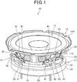
- Figure 1 is a perspective view of a loudspeaker 10 according to a first embodiment.
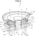
- Figure 2 is a cross-sectional view of the loudspeaker 10.
- Figure 1 and Figure 2 show a state in which a front surface of the loudspeaker 10 is arranged so as to be directed upward.
- the loudspeaker 10 is an on-vehicle digital loudspeaker which is mounted on a vehicle door, etc., receives a digital signal as an input from a device mounted on a vehicle, and outputs a sound based on this digital signal.
- this loudspeaker 10 includes a loudspeaker frame 11 whose front surface is open; and a diaphragm 13, voice coil bobbin 15, and magnetic circuit section 17, which constitute loudspeaker components, are supported by this loudspeaker frame 11.
- the loudspeaker frame 11 integrally includes: an annular front frame 11A that is positioned at a frontmost surface of the loudspeaker 10; a disk-shaped bottom frame 11B that is positioned on a rear surface side of the loudspeaker 10; and a plurality of bridge frames 11C that connect the front frame 11A and the bottom frame 11B at intervals in a circumferential direction.
- the loudspeaker frame 11 is formed of a material having rigidity; and in this configuration, is formed of a metal material.
- an outer peripheral part of the diaphragm 13 is mounted on the front frame 11A.
- An inner peripheral part of the diaphragm 13 is connected to the voice coil bobbin 15.
- a damper 19 that connects the voice coil bobbin 15 and the loudspeaker frame 11 is provided. The damper 19 holds the position of the voice coil bobbin 15 and performs amplitude limitation.
- a through hole 11K through which the voice coil bobbin 15 passes is formed; and on a rear surface of this bottom frame 11B, the magnetic circuit section 17 is mounted.
- the magnetic circuit section 17 has a structure in which from a front surface side of the loudspeaker toward a rear surface side, a plate 21 (also referred to as a top plate), a magnet 22, and a bottom plate 23 (also referred to as a yoke) are laminated in order.
- the magnet 22 is sandwiched by the plate 21 and the bottom plate 23 and the voice coil bobbin 15 is arranged in a centrally provided hole part 17K.
- the plate 21 and the bottom plate 23 are formed by a magnetic material.
- the magnet 22 is configured by magnetizing a ferrite core of an approximate doughnut shape; for example, it is configured by a ferromagnetic ferrite magnet.
- the voice coil bobbin 15 is of a multilayer voice coil bobbin in which a plurality of (four, in the present configuration) voice coils 31 are laminated on a single bobbin 15A.
- Each of the voice coils 31 is configured by a copper wire excellent in flexibility and lightweight properties; and first conductive bodies 41 corresponding to both end parts of the copper wire are led out to an outside of the bobbin 15A.
- each pair of the first conductive bodies 41 which are connected to an identical one of the voice coils 31 is led out to the outside of the bobbin 15A at equal angular intervals and is connected to each of the terminal blocks 33.
- Each of the terminal blocks 33 is configured by a metal plate, etc. and is mounted on the bridge frame 11C of the loudspeaker frame 11 from an outer peripheral side.
- each of the plurality of first conductive bodies 41 which extend from the voice coil bobbin 15 is connected.
- the terminal blocks 33 are provided with the same number as the voice coils 31; and to each of the terminal blocks 33, a pair of the first conductive bodies 41 which extend from an identical one of the voice coils 31 is connected.
- each pair of second conductive bodies 51 is connected from an outer peripheral side of the loudspeaker 10.
- the pair of second conductive bodies 51 is respectively connected to a pair of the first conductive bodies 41 that are connected to the respective terminal blocks 33; and is externally supplied with a digital signal.
- each of the terminal blocks 33 functions as a relay member for relaying connection between a pair of the first conductive bodies 41 and a pair of the second conductive bodies 51. It should be noted that for a method for connecting the conductive bodies 41 and 51 to the terminal blocks 33, a publicly known method such as soldering can be widely applied.
- a coated electric wire 52 in which a coating having an insulating property is covered around a core wire is applied.
- one end of this coated electric wire 52 is connected to a predetermined device that outputs a digital signal and another end is connected to the terminal block 33 of the loudspeaker 10, thereby constituting a so-called loudspeaker cable that extends over between the predetermined device and the loudspeaker 10.
- the coated electric wire 52 is led out from the terminal block 33; penetrates the plate 21, magnet 22, and bottom plate 23 in order which constitute the magnetic circuit section 17; and is led out to the rear surface side of the loudspeaker 10.
- the coated electric wire 52 in connecting the coated electric wire 52 to the loudspeaker 10, the coated electric wire 52 is connected such that a tip of the coated electric wire 52, which penetrates the magnetic circuit section 17 from the rear surface side of the loudspeaker 10 and is exposed to a front surface side of the magnetic circuit section 17, is connected to the terminal block 33.
- Figure 3 is a diagram showing the loudspeaker 10 in a state in which components of the magnetic circuit section 17 are separated.
- the plate 21 is laminated in a front surface side of the loudspeaker 10 with respect to the magnet 22, and the bottom plate 23 is laminated on a rear surface side of the loudspeaker 10 with respect to the magnet 22. That is, the plate 21 and the bottom plate 23 are laminated components which are laminated on the magnet 22. In addition, the plate 21 and the bottom plate 23 are joined to the magnet 22 with an adhesive or the like.
- the plate 21 and the magnet 22 are annularly formed so as to respectively have, in a center thereof, through holes 21K and 22K through which the voice coil bobbin 15 passes. These through holes 21K and 22K form the hole part 17K (see Figure 2 ) of the magnetic circuit section 17.
- the through hole 21K which is provided on the plate 21 is represented as a plate through hole 21K
- the through hole 21K which is provided on the magnet 22 is represented as a magnet through hole 22K.
- the magnet through hole 22K is a through hole having a larger diameter than the plate through hole 21K.
- the magnet 22 integrally includes groove parts 22M (magnet wiring holes) that are recessed on an outer peripheral side at predetermined angular intervals (at 90 degree intervals in the present configuration) from the magnet through hole 22K. These groove parts 22M configure, as shown in Figure 3 , paths through which each pair of the coated electric wires 52 can pass. It should be noted that these groove parts 22M are partially formed on the magnet 22; and therefore, they hardly affect the performance of the loudspeaker 10.
- the magnet 22 is a sintered magnet that is manufactured in a publicly known method such as a powder metallurgy method, in which difficulties are involved in obtaining a complicated shape; however, a shape in which the above groove parts 22M are integrally included can be easily prepared.
- through holes 21A and 23A are respectively formed at positions that communicate with the groove parts 22M when lamination with the magnet 22 is performed. Thus, a path that allows the coated electric wires 52 to penetrate the magnetic circuit section 17 is formed.
- the through hole 21A is represented as a plate hole part 21A
- the through hole 23A is represented as a bottom plate hole part 23A.
- the plate hole part 21A is an independent through hole that does not communicate with the plate through hole 21K on the plate 21, and is provided closer to an outer peripheral surface of the plate 21. Adoption of this configuration allows suppression of the deterioration of a magnetic force that acts on the voice coil bobbin 15, in comparison with a case in which recessed shapes similar to the groove parts 22M of the magnet 22 are provided on an inner side of the plate 21.
- the plate hole part 21A is not open either in a circumferential direction or radial direction of the plate 21 and therefore, restricts the movement of the coated electric wires 52 in the circumferential direction and radial direction. Therefore, it is suitable for positioning of the coated electric wires 52 having flexibility.
- the bottom plate hole part 23A is a notch that is recessed from an outer peripheral surface of the bottom plate 23 to an inner peripheral side; and therefore, entry of dust and the like can be suppressed.
- an outer peripheral side of the bottom plate hole part 23A is open; and therefore, such an effect that the coated electric wires 52 can be easily inserted from an outside can also be expected.
- the shapes and positions of the plate hole parts 21A and the bottom plate hole parts 23A can be appropriately changed.
- the plate hole parts 21A, the groove parts 22M of the magnet 22, and the bottom plate hole parts 23A are provided at the same angular intervals as the plurality of terminal blocks 33 which are provided on the loudspeaker frame 11; and therefore, the coated electric wires 52 can be linearly laid out, thus providing advantages in reduction of wiring length, securing of a wiring arrangement space, and the like.
- the coated electric wires 52 constituting the second conductive bodies 51 are made to penetrate the magnet 22 and thereby, the magnet 22 can be used as a ferrite core that removes a high frequency noise that flows through the second conductive bodies 51.
- the impedance Z of a ferrite core is, as shown in the following expression (1), proportional to a cross-sectional area.
- the impedance Z is proportional to the second power of the number of windings N (also called as the number of turns) of a signal line to an inner hole and outside of the ferrite core.
- N also called as the number of turns
- the magnet 22 of the loudspeaker 10 is larger in comparison with common ferrite cores; and therefore, a higher noise removal effect than that in common ferrite cores can be expected.
- the groove parts 22M are provided in plurality within the magnet 22 and through each of the groove parts 22M, a plurality of the second conductive bodies 51 are passed in a distributed manner; therefore, each of the groove parts 22M can be miniaturized and the reduction of the impedance Z, etc. can be easily suppressed.
- the loudspeaker 10 of the present embodiment includes: the first conductive bodies 41 which are connected to the voice coil 31 and are led out to the outside of the bobbin 15A; and the second conductive bodies 51 which are connected to the first conductive bodies 41 and penetrate the magnet 22. According to this configuration, a high frequency noise that flows through the second conductive bodies 51 can be removed by using the magnet22 included in the magnetic circuit section 17.
- noises can be removed without adding a ferrite core for noise countermeasures; and therefore, noise countermeasures for the loudspeaker 10 is possible by means of a simple configuration and further, securing a ferrite core arrangement space is unnecessary.
- a signal to be passed through the second conductive bodies 51 is a digital signal; and therefore, countermeasures against a high frequency noise superimposed on the digital signal can be achieved in a vicinity of the loudspeaker.
- influences on electronic apparatuses around the loudspeaker 10 can be reduced and also, improvement in the sound quality of the loudspeaker 10 can be expected.
- the coated electric wires 52 are used; and therefore, an insulating property against parts of the magnetic circuit section 17 can be ensured.
- materials, etc. used for the magnetic circuit section 17 are not limited.
- a member having a conductive property can be arranged around the second conductive bodies 51.
- the magnet 22 is provided with: the magnet through hole 22K through which the bobbin 15A passes; and the groove parts 22M which are recessed from this through hole 22K to the outer peripheral side and through which the second conductive bodies 51 pass. This allows the second conductive bodies 51 to penetrate, allows an influence on the performance of the loudspeaker 10 to be suppressed, and allows the magnet 22 to be easily manufactured.
- the magnetic circuit section 17 includes the plate 21 and bottom plate 23 that are laminated components which are laminated on the magnet 22; and the second conductive bodies 51 pass through the plate 21 and the bottom plate 23. This eliminates the need to make the second conductive bodies 51 bypass the plate 21 and the bottom plate 23; providing advantages in reduction of wiring length, securing of a wiring arrangement space, and the like.
- the plate 21 is provided with: the plate through hole 21K through which the bobbin 15A passes; and the independent plate hole parts 21A which do not communicate with this through hole 21K and through which the second conductive bodies 51 pass. This allows the second conductive bodies 51 to penetrate and allows the reduction of a magnetic force of the plate 21 to be suppressed.
- the bottom plate 23 is provided with, as the bottom plate hole parts 23A through which the second conductive bodies 51 pass, notches which are recessed from an outer peripheral surface of the bottom plate 23 to an inner peripheral side and through which the second conductive bodies 51 pass. This allows the second conductive bodies 51 to penetrate and allows entry of dust, etc. into a gap between the bottom plate 23 and the bobbin 15A to be suppressed.
- the voice coil bobbin 15 includes a multilayer voice coil in which a plurality of the voice coils 31 are provided; and from the voice coil bobbin 15, a plurality of the first conductive bodies 41 which are respectively connected to the voice coils 31 are led out at intervals in a circumferential direction. Further, a plurality of the second conductive bodies 51 which are respectively connected to the first conductive bodies 41 are configured to pass through the magnet 22 at intervals in the circumferential direction of the voice coil bobbin 15. According to this configuration, a number of the first conductive bodies 41 and second conductive bodies 51 can be arranged at intervals in a balanced manner.
- Figure 4 is a cross-sectional view of a loudspeaker 10 according to a second embodiment.
- each of second conductive bodies 51 passes hole parts of a magnetic circuit section 17 (a bottom plate hole part 23A, groove part 22M, and plate hole part 21A) in order from an outside of the loudspeaker 10; after that, returns to a rear surface side of the magnetic circuit section 17 by passing through an outer peripheral side of the magnetic circuit section 17; and again, passes through the hole part 23A, 22M, and 21A of the magnetic circuit section 17 in order and is then connected to each of terminal blocks 33.
- the second conductive body 51 is wound around a magnet 22 in the number of windings with one turn.
- An increase in the number of windings can increase the impedance Z, thereby allowing a noise removal characteristic to be changed and a noise removal effect to be improved. It should be noted that the number of windings is not limited to one turn and may be appropriately changed to two or more turns.
- the bottom plate hole parts 23A are not notches that are recessed from an outer peripheral surface of the bottom plate 23 to an inner peripheral side; but are formed as independent through holes as with the plate hole parts 21A of the first embodiment. This allows the bottom plate 23 in addition to the plate 21 and the magnet 22 to be held in a laminated state by the second conductive bodies 51.
- Figure 5 is a cross-sectional view of a loudspeaker 10 according to a third embodiment.
- the third embodiment is different from the first embodiment in that portions through which second conductive bodies 51 pass on a magnet 22 are hole parts 22S (hereinafter, represented as magnet wiring holes 22S) which are independent of a magnet through hole 22K.
- Each of the magnet wiring hole 22S is formed as a through hole that linearly penetrates the magnet 22 so as to communicate with a plate hole part 21A and a bottom plate hole part 23A.
- the magnet wiring holes 22S are formed at intervals (equal angular intervals) in the circumferential direction of the loudspeaker 10 as with the plate hole parts 21A and the bottom plate hole parts 23A.
- the inner diameter of each of the hole parts through which the second conductive bodies 51 pass (that is, the inner diameter of each of the magnet wiring holes 22S) can be reduced and thereby, as shown in Expression (1), the impedance Z can be increased.
- the cross-sectional area of the magnet 22 increases; this also allows an increase in the impedance Z. As a result, a higher noise removal effect can be obtained and a noise removal characteristic can be changed.
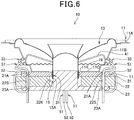
- the second conductive bodies 51 can be wound around the magnet 22 in the number of windings with a plurality of turns.
- a configuration is such that coated electric wires 52 are not allowed to penetrate a magnet 22.
- Figure 7 is a cross-sectional view of a loudspeaker 10 according to the fourth embodiment.
- Figure 8 is a diagram showing the loudspeaker 10 in a state in which components of a magnetic circuit section are separated.
- a terminal block 33 which is provided on a loudspeaker frame 11 integrally includes a second conductive body 151 that penetrates a magnetic circuit section 17.
- the second conductive body 151 integrally includes: a terminal 152 that is formed integrally with the terminal block 33 and extends toward a rear surface side of the loudspeaker 10; and an insulating part 153 for peripheral covering with a tip of the terminal 152 exposed.
- the terminal 152 is formed of a material having conductivity such as metal, and is formed to have a length which allows a tip 152A to penetrate the magnetic circuit section 17 and to be exposed to a rear surface side of the magnetic circuit section 17.
- the insulating part 153 is formed of a resin having an insulating property, and covers a region overlapping with the magnetic circuit section 17 on the terminal 152.
- this second conductive body 151 is manufactured by performing insert molding of the terminal 152 on the resin constituting the insulating part 153.
- through holes 121A and 123A (hereinafter, represented as a plate hole part 121A and a bottom plate hole part 123A) which the second conductive body 151 penetrates are respectively formed.
- the plate hole part 121A and the bottom plate hole part 123A communicate with a groove part 22M that is provided on a magnet 22.
- the second conductive body 151 penetrates the magnetic circuit section 17 and thereby, the tip 152A of the terminal 152 which is provided on the second conductive body 151 is exposed to the rear surface side of the magnetic circuit section 17. Further, to this exposed tip 152A, an unillustrated coated electric wire for transmitting a digital signal is connected.
- first conductive bodies 41 and second conductive bodies 51 and 151 a member permitting an electric signal to pass, that is, a member having conductivity (also called as a conductive member or a conductive body) can be widely applied.
- first conductive bodies 41 have flexibility.
- each of the second conductive bodies 51 and 151 in the above mentioned embodiments integrally includes an insulating body (coating, corresponding to the insulating part 153), the insulating body may be configured so as to be mounted not on each of second conductive bodies 51 and 151 sides but on a side of a member with which each of the second conductive bodies 51 and 151 can come into contact.
Landscapes
- Engineering & Computer Science (AREA)
- Physics & Mathematics (AREA)
- Acoustics & Sound (AREA)
- Signal Processing (AREA)
- Multimedia (AREA)
- Audible-Bandwidth Dynamoelectric Transducers Other Than Pickups (AREA)
Abstract
Description
- The present invention relates to a loudspeaker.
- A loudspeaker, which includes a bobbin provided with a voice coil, a diaphragm connected to the bobbin, a frame supporting the diaphragm, and a magnetic circuit section including a magnet, is known. This type of loudspeaker is known to have such a configuration that a terminal which is electrically connected with a voice coil is included and a signal line (part of a loudspeaker line) for connecting the loudspeaker and an amplifier is soldered directly on a terminal from the outside of the loudspeaker or is connected by a connector (for example, Patent Literature 1).
- In addition, as this type of loudspeaker, a so-called full digital loudspeaker is proposed which includes a plurality of voice coils and obtains, by supply of a predetermined digital signal to each of the voice coils, a sufficient loudspeaker driving force by adding a magnetic field formed by each of the voice coils (for example, Patent Literature 2).
-
- Patent Literature 1
Japanese Patent Laid-Open No.2015-080121 -
Patent Literature 2
Japanese Patent Laid-Open No.2015-126463 - For wiring on the loudspeaker side, especially for internal wiring, flexibility and lightweight properties are required; and therefore, wiring having a twisted structure or the like that is suitable for noise countermeasures cannot be used.
- Therefore, if a high-frequency noise that causes unnecessary radiation is input to a wiring on the loudspeaker side through a loudspeaker line, an electronic apparatus around the loudspeaker may malfunction. Especially when a digital signal is used, countermeasures against a higher frequency noise are important.
- As the countermeasure, a method of mounting a ferrite core for noise countermeasures can be considered. However, this method causes an increase in the number of parts and further generates a necessity to secure an arrangement space of the ferrite core, thereby making the structure complicated.
- Therefore, it is an object of the present invention to make it possible to take countermeasures against noises of a loudspeaker by means of a simple configuration.
- The present description includes the entire contents of Japanese Patent Application No.
2017-125809 filed on June 28, 2017 - In order to achieve the above-mentioned object, one aspect of the present invention provides a loudspeaker that includes a bobbin provided with a voice coil, a diaphragm connected to the bobbin, a frame supporting the diaphragm, and a magnetic circuit section including a magnet, in which the loudspeaker further includes a first conductive body connected to the voice coil and led out to an outside of the bobbin, and a second conductive body connected to the first conductive body and penetrating the magnet.
- In the above configuration, the second conductive body may be a coated electric wire covered with a coating having an insulating property. In addition, in the above configuration, the second conductive body may be wound around the magnet in the number of windings with one or more turns.
- In addition, in the above configuration, the magnet may be provided with: a through hole through which the bobbin passes; and a groove part which is recessed from the through hole to an outer peripheral side and through which the second conductive body passes. In addition, instead of the groove part, a hole part which is independent of the through hole and through which the second conductive body passes may be provided.
- In addition, in the above configuration, the magnetic circuit section may include laminated components which are laminated on the magnet and the second conductive body may pass through the laminated components.
- In addition, in the above configuration, the laminated components may include: a plate which is laminated on a front surface side of the loudspeaker with respect to the magnet; and a bottom plate which is laminated on a rear surface side of the loudspeaker; and the plate may be provided with: a hole part through which the bobbin passes; and an independent through hole which does not communicate with this hole part and through which the second conductive body passes; and the bottom plate may be provided with: a notch which is recessed from an outer peripheral surface of the bottom plate to an inner peripheral side and through which the second conductive body passes.
- In addition, in the above configuration, a signal which is passed through the second conductive body may be a digital signal.
- Further, in the above configuration, the bobbin may include a multilayer voice coil in which a plurality of the voice coils are provided; from the bobbin, a plurality of the first conductive bodies which are respectively connected to the voice coils may be led out at intervals in a circumferential direction; and a plurality of the second conductive bodies which are respectively connected to the first conductive bodies may pass through the magnet at intervals in the circumferential direction of the bobbin.
- One aspect of the present invention includes: the first conductive body which is connected to the voice coil and is led out to an outside of the bobbin; and the second conductive body which is connected to the first conductive body and penetrates the magnet included in the magnetic circuit section; and therefore, can remove a high frequency noise flowing through the second conductive body by using the magnet included in the magnetic circuit section, thereby allowing noise countermeasures of the loudspeaker by means of a simple configuration.
-
- [
Figure 1] Figure 1 is a perspective view of a loudspeaker according to a first embodiment. - [
Figure 2] Figure 2 is a cross-sectional view of the loudspeaker. - [
Figure 3] Figure 3 is a diagram showing the loudspeaker in a state in which components of the magnetic circuit section are separated. - [
Figure 4] Figure 4 is a cross-sectional view of a loudspeaker according to a second embodiment. - [
Figure 5] Figure 5 is a cross-sectional view of a loudspeaker according to a third embodiment. - [
Figure 6] Figure 6 is a cross-sectional view of a loudspeaker which is provided for description of a modification. - [
Figure 7] Figure 7 is a cross-sectional view of a loudspeaker according to a fourth embodiment. - [
Figure 8] Figure 8 is a diagram showing the loudspeaker in a state in which components of the magnetic circuit section are separated. - Hereinafter, embodiments of the present invention will be described with reference to drawings.
-
Figure 1 is a perspective view of aloudspeaker 10 according to a first embodiment.Figure 2 is a cross-sectional view of theloudspeaker 10.Figure 1 andFigure 2 show a state in which a front surface of theloudspeaker 10 is arranged so as to be directed upward. - The
loudspeaker 10 is an on-vehicle digital loudspeaker which is mounted on a vehicle door, etc., receives a digital signal as an input from a device mounted on a vehicle, and outputs a sound based on this digital signal. As shown inFigure 1 andFigure 2 , thisloudspeaker 10 includes aloudspeaker frame 11 whose front surface is open; and adiaphragm 13,voice coil bobbin 15, andmagnetic circuit section 17, which constitute loudspeaker components, are supported by thisloudspeaker frame 11. - The
loudspeaker frame 11 integrally includes: anannular front frame 11A that is positioned at a frontmost surface of theloudspeaker 10; a disk-shaped bottom frame 11B that is positioned on a rear surface side of theloudspeaker 10; and a plurality ofbridge frames 11C that connect thefront frame 11A and thebottom frame 11B at intervals in a circumferential direction. Theloudspeaker frame 11 is formed of a material having rigidity; and in this configuration, is formed of a metal material. - On the
front frame 11A, an outer peripheral part of thediaphragm 13 is mounted. An inner peripheral part of thediaphragm 13 is connected to thevoice coil bobbin 15. Between a rear surface of thediaphragm 13 and thebottom frame 11B, adamper 19 that connects thevoice coil bobbin 15 and theloudspeaker frame 11 is provided. Thedamper 19 holds the position of thevoice coil bobbin 15 and performs amplitude limitation. - As shown in
Figure 2 , on thebottom frame 11B, athrough hole 11K through which thevoice coil bobbin 15 passes is formed; and on a rear surface of thisbottom frame 11B, themagnetic circuit section 17 is mounted. - The
magnetic circuit section 17 has a structure in which from a front surface side of the loudspeaker toward a rear surface side, a plate 21 (also referred to as a top plate), amagnet 22, and a bottom plate 23 (also referred to as a yoke) are laminated in order. - In the
magnetic circuit section 17, themagnet 22 is sandwiched by theplate 21 and thebottom plate 23 and thevoice coil bobbin 15 is arranged in a centrally providedhole part 17K. Theplate 21 and thebottom plate 23 are formed by a magnetic material. Themagnet 22 is configured by magnetizing a ferrite core of an approximate doughnut shape; for example, it is configured by a ferromagnetic ferrite magnet. - The
voice coil bobbin 15 is of a multilayer voice coil bobbin in which a plurality of (four, in the present configuration)voice coils 31 are laminated on asingle bobbin 15A. Each of thevoice coils 31 is configured by a copper wire excellent in flexibility and lightweight properties; and firstconductive bodies 41 corresponding to both end parts of the copper wire are led out to an outside of thebobbin 15A. - In the
loudspeaker frame 11, a plurality of (four, in the present configuration)terminal blocks 33, to which the firstconductive bodies 41 are respectively connected, are provided at intervals (at equal angular (90 degree) intervals in the present configuration) in a circumferential direction of theloudspeaker 10. In this way, each pair of the firstconductive bodies 41 which are connected to an identical one of thevoice coils 31 is led out to the outside of thebobbin 15A at equal angular intervals and is connected to each of theterminal blocks 33. - Each of the
terminal blocks 33 is configured by a metal plate, etc. and is mounted on thebridge frame 11C of theloudspeaker frame 11 from an outer peripheral side. In addition, on a rear surface side of each of the terminal blocks 33 (corresponding to an inner peripheral side of the loudspeaker 10), each of the plurality of firstconductive bodies 41 which extend from thevoice coil bobbin 15 is connected. The terminal blocks 33 are provided with the same number as the voice coils 31; and to each of the terminal blocks 33, a pair of the firstconductive bodies 41 which extend from an identical one of the voice coils 31 is connected. - To each of the terminal blocks 33, each pair of second
conductive bodies 51 is connected from an outer peripheral side of theloudspeaker 10. The pair of secondconductive bodies 51 is respectively connected to a pair of the firstconductive bodies 41 that are connected to the respective terminal blocks 33; and is externally supplied with a digital signal. - Thus, each of the terminal blocks 33 functions as a relay member for relaying connection between a pair of the first
conductive bodies 41 and a pair of the secondconductive bodies 51. It should be noted that for a method for connecting theconductive bodies - In the present embodiment, for each of the second
conductive bodies 51, a coatedelectric wire 52 in which a coating having an insulating property is covered around a core wire is applied. For example, one end of this coatedelectric wire 52 is connected to a predetermined device that outputs a digital signal and another end is connected to theterminal block 33 of theloudspeaker 10, thereby constituting a so-called loudspeaker cable that extends over between the predetermined device and theloudspeaker 10. - As shown in
Figure 2 , the coatedelectric wire 52 is led out from theterminal block 33; penetrates theplate 21,magnet 22, andbottom plate 23 in order which constitute themagnetic circuit section 17; and is led out to the rear surface side of theloudspeaker 10. In other words, in connecting the coatedelectric wire 52 to theloudspeaker 10, the coatedelectric wire 52 is connected such that a tip of the coatedelectric wire 52, which penetrates themagnetic circuit section 17 from the rear surface side of theloudspeaker 10 and is exposed to a front surface side of themagnetic circuit section 17, is connected to theterminal block 33. -
Figure 3 is a diagram showing theloudspeaker 10 in a state in which components of themagnetic circuit section 17 are separated. - The
plate 21 is laminated in a front surface side of theloudspeaker 10 with respect to themagnet 22, and thebottom plate 23 is laminated on a rear surface side of theloudspeaker 10 with respect to themagnet 22. That is, theplate 21 and thebottom plate 23 are laminated components which are laminated on themagnet 22. In addition, theplate 21 and thebottom plate 23 are joined to themagnet 22 with an adhesive or the like. - The
plate 21 and themagnet 22 are annularly formed so as to respectively have, in a center thereof, throughholes voice coil bobbin 15 passes. These throughholes hole part 17K (seeFigure 2 ) of themagnetic circuit section 17. - Hereinafter, in order to easily distinguish between the through
holes hole 21K which is provided on theplate 21 is represented as a plate throughhole 21K, and the throughhole 21K which is provided on themagnet 22 is represented as a magnet throughhole 22K. - The magnet through
hole 22K is a through hole having a larger diameter than the plate throughhole 21K. In addition, themagnet 22 integrally includesgroove parts 22M (magnet wiring holes) that are recessed on an outer peripheral side at predetermined angular intervals (at 90 degree intervals in the present configuration) from the magnet throughhole 22K. Thesegroove parts 22M configure, as shown inFigure 3 , paths through which each pair of the coatedelectric wires 52 can pass. It should be noted that thesegroove parts 22M are partially formed on themagnet 22; and therefore, they hardly affect the performance of theloudspeaker 10. - Further, the
magnet 22 is a sintered magnet that is manufactured in a publicly known method such as a powder metallurgy method, in which difficulties are involved in obtaining a complicated shape; however, a shape in which theabove groove parts 22M are integrally included can be easily prepared. - On the
plate 21 and thebottom plate 23, throughholes groove parts 22M when lamination with themagnet 22 is performed. Thus, a path that allows the coatedelectric wires 52 to penetrate themagnetic circuit section 17 is formed. - Hereinafter, in order to easily distinguish between the through
holes hole 21A is represented as aplate hole part 21A, and the throughhole 23A is represented as a bottomplate hole part 23A. - The
plate hole part 21A is an independent through hole that does not communicate with the plate throughhole 21K on theplate 21, and is provided closer to an outer peripheral surface of theplate 21. Adoption of this configuration allows suppression of the deterioration of a magnetic force that acts on thevoice coil bobbin 15, in comparison with a case in which recessed shapes similar to thegroove parts 22M of themagnet 22 are provided on an inner side of theplate 21. - In addition, the
plate hole part 21A is not open either in a circumferential direction or radial direction of theplate 21 and therefore, restricts the movement of the coatedelectric wires 52 in the circumferential direction and radial direction. Therefore, it is suitable for positioning of the coatedelectric wires 52 having flexibility. - On the
bottom plate 23, if recessed shapes similar to thegroove parts 22M of themagnet 22 are provided, there is a concern that dust and the like may enter a gap between thebottom plate 23 and thevoice coil bobbin 15. - In the present configuration, the bottom
plate hole part 23A is a notch that is recessed from an outer peripheral surface of thebottom plate 23 to an inner peripheral side; and therefore, entry of dust and the like can be suppressed. - In addition, an outer peripheral side of the bottom
plate hole part 23A is open; and therefore, such an effect that the coatedelectric wires 52 can be easily inserted from an outside can also be expected. - Further, the shapes and positions of the
plate hole parts 21A and the bottomplate hole parts 23A can be appropriately changed. - As shown in
Figure 3 , theplate hole parts 21A, thegroove parts 22M of themagnet 22, and the bottomplate hole parts 23A are provided at the same angular intervals as the plurality of terminal blocks 33 which are provided on theloudspeaker frame 11; and therefore, the coatedelectric wires 52 can be linearly laid out, thus providing advantages in reduction of wiring length, securing of a wiring arrangement space, and the like. - Thus, the coated
electric wires 52 constituting the secondconductive bodies 51 are made to penetrate themagnet 22 and thereby, themagnet 22 can be used as a ferrite core that removes a high frequency noise that flows through the secondconductive bodies 51. - The impedance Z of a ferrite core is, as shown in the following expression (1), proportional to a cross-sectional area. In addition, the impedance Z is proportional to the second power of the number of windings N (also called as the number of turns) of a signal line to an inner hole and outside of the ferrite core. In addition, it is known that the smaller the inner diameter of the inner hole of a ferrite core, the more the impedance Z increases.
[Expression 1]
- The
magnet 22 of theloudspeaker 10 is larger in comparison with common ferrite cores; and therefore, a higher noise removal effect than that in common ferrite cores can be expected. In addition, thegroove parts 22M are provided in plurality within themagnet 22 and through each of thegroove parts 22M, a plurality of the secondconductive bodies 51 are passed in a distributed manner; therefore, each of thegroove parts 22M can be miniaturized and the reduction of the impedance Z, etc. can be easily suppressed. - As described above, the
loudspeaker 10 of the present embodiment includes: the firstconductive bodies 41 which are connected to thevoice coil 31 and are led out to the outside of thebobbin 15A; and the secondconductive bodies 51 which are connected to the firstconductive bodies 41 and penetrate themagnet 22. According to this configuration, a high frequency noise that flows through the secondconductive bodies 51 can be removed by using the magnet22 included in themagnetic circuit section 17. - In addition, noises can be removed without adding a ferrite core for noise countermeasures; and therefore, noise countermeasures for the
loudspeaker 10 is possible by means of a simple configuration and further, securing a ferrite core arrangement space is unnecessary. - In addition, a signal to be passed through the second
conductive bodies 51 is a digital signal; and therefore, countermeasures against a high frequency noise superimposed on the digital signal can be achieved in a vicinity of the loudspeaker. Thus, influences on electronic apparatuses around theloudspeaker 10 can be reduced and also, improvement in the sound quality of theloudspeaker 10 can be expected. - Further, for the second
conductive bodies 51 that penetrate themagnetic circuit section 17, the coatedelectric wires 52 are used; and therefore, an insulating property against parts of themagnetic circuit section 17 can be ensured. Thus, materials, etc. used for themagnetic circuit section 17 are not limited. In addition, around the secondconductive bodies 51, a member having a conductive property can be arranged. - Further, the
magnet 22 is provided with: the magnet throughhole 22K through which thebobbin 15A passes; and thegroove parts 22M which are recessed from this throughhole 22K to the outer peripheral side and through which the secondconductive bodies 51 pass. This allows the secondconductive bodies 51 to penetrate, allows an influence on the performance of theloudspeaker 10 to be suppressed, and allows themagnet 22 to be easily manufactured. - In addition, the
magnetic circuit section 17 includes theplate 21 andbottom plate 23 that are laminated components which are laminated on themagnet 22; and the secondconductive bodies 51 pass through theplate 21 and thebottom plate 23. This eliminates the need to make the secondconductive bodies 51 bypass theplate 21 and thebottom plate 23; providing advantages in reduction of wiring length, securing of a wiring arrangement space, and the like. - Further, the
plate 21 is provided with: the plate throughhole 21K through which thebobbin 15A passes; and the independentplate hole parts 21A which do not communicate with this throughhole 21K and through which the secondconductive bodies 51 pass. This allows the secondconductive bodies 51 to penetrate and allows the reduction of a magnetic force of theplate 21 to be suppressed. - In addition, the
bottom plate 23 is provided with, as the bottomplate hole parts 23A through which the secondconductive bodies 51 pass, notches which are recessed from an outer peripheral surface of thebottom plate 23 to an inner peripheral side and through which the secondconductive bodies 51 pass. This allows the secondconductive bodies 51 to penetrate and allows entry of dust, etc. into a gap between thebottom plate 23 and thebobbin 15A to be suppressed. - In addition, the
voice coil bobbin 15 includes a multilayer voice coil in which a plurality of the voice coils 31 are provided; and from thevoice coil bobbin 15, a plurality of the firstconductive bodies 41 which are respectively connected to the voice coils 31 are led out at intervals in a circumferential direction. Further, a plurality of the secondconductive bodies 51 which are respectively connected to the firstconductive bodies 41 are configured to pass through themagnet 22 at intervals in the circumferential direction of thevoice coil bobbin 15. According to this configuration, a number of the firstconductive bodies 41 and secondconductive bodies 51 can be arranged at intervals in a balanced manner. -
Figure 4 is a cross-sectional view of aloudspeaker 10 according to a second embodiment. - As shown in
Figure 4 , each of secondconductive bodies 51 passes hole parts of a magnetic circuit section 17 (a bottomplate hole part 23A,groove part 22M, andplate hole part 21A) in order from an outside of theloudspeaker 10; after that, returns to a rear surface side of themagnetic circuit section 17 by passing through an outer peripheral side of themagnetic circuit section 17; and again, passes through thehole part magnetic circuit section 17 in order and is then connected to each of terminal blocks 33. - As a result, the second
conductive body 51 is wound around amagnet 22 in the number of windings with one turn. An increase in the number of windings can increase the impedance Z, thereby allowing a noise removal characteristic to be changed and a noise removal effect to be improved. It should be noted that the number of windings is not limited to one turn and may be appropriately changed to two or more turns. - In a configuration in which the second
conductive bodies 51 are wound, increasing a tension in winding the secondconductive bodies 51 enables themagnetic circuit section 17 to be bound. Binding themagnetic circuit section 17 enables a holding force for holding components of themagnetic circuit section 17 in a laminated state to be obtained. - Here, in the present embodiment, the bottom
plate hole parts 23A are not notches that are recessed from an outer peripheral surface of thebottom plate 23 to an inner peripheral side; but are formed as independent through holes as with theplate hole parts 21A of the first embodiment. This allows thebottom plate 23 in addition to theplate 21 and themagnet 22 to be held in a laminated state by the secondconductive bodies 51. - According to this configuration, a configuration in which an adhesive for joining the
plate 21, themagnet 22, and thebottom plate 23 with each other is not used is made possible. By adopting a configuration in which an adhesive is not used, the layer thickness of an adhesive is eliminated and thereby the magnetic force of themagnetic circuit section 17 can be efficiently improved. -
Figure 5 is a cross-sectional view of aloudspeaker 10 according to a third embodiment. - The third embodiment is different from the first embodiment in that portions through which second
conductive bodies 51 pass on amagnet 22 arehole parts 22S (hereinafter, represented as magnet wiring holes 22S) which are independent of a magnet throughhole 22K. - Each of the
magnet wiring hole 22S is formed as a through hole that linearly penetrates themagnet 22 so as to communicate with aplate hole part 21A and a bottomplate hole part 23A. Themagnet wiring holes 22S are formed at intervals (equal angular intervals) in the circumferential direction of theloudspeaker 10 as with theplate hole parts 21A and the bottomplate hole parts 23A. - In this configuration, the inner diameter of each of the hole parts through which the second
conductive bodies 51 pass (that is, the inner diameter of each of the magnet wiring holes 22S) can be reduced and thereby, as shown in Expression (1), the impedance Z can be increased. In addition, as the hole part is made smaller, the cross-sectional area of themagnet 22 increases; this also allows an increase in the impedance Z. As a result, a higher noise removal effect can be obtained and a noise removal characteristic can be changed. - In addition, also in the third embodiment, as one example is shown in
Figure 6 , the secondconductive bodies 51 can be wound around themagnet 22 in the number of windings with a plurality of turns. - In a fourth embodiment, a configuration is such that coated
electric wires 52 are not allowed to penetrate amagnet 22. -
Figure 7 is a cross-sectional view of aloudspeaker 10 according to the fourth embodiment. In addition,Figure 8 is a diagram showing theloudspeaker 10 in a state in which components of a magnetic circuit section are separated. - In the fourth embodiment, a
terminal block 33 which is provided on aloudspeaker frame 11 integrally includes a secondconductive body 151 that penetrates amagnetic circuit section 17. The secondconductive body 151 integrally includes: a terminal 152 that is formed integrally with theterminal block 33 and extends toward a rear surface side of theloudspeaker 10; and aninsulating part 153 for peripheral covering with a tip of the terminal 152 exposed. - The terminal 152 is formed of a material having conductivity such as metal, and is formed to have a length which allows a
tip 152A to penetrate themagnetic circuit section 17 and to be exposed to a rear surface side of themagnetic circuit section 17. The insulatingpart 153 is formed of a resin having an insulating property, and covers a region overlapping with themagnetic circuit section 17 on theterminal 152. For example, this secondconductive body 151 is manufactured by performing insert molding of the terminal 152 on the resin constituting the insulatingpart 153. - As shown in
Figure 8 , on aplate 21 and abottom plate 23, throughholes plate hole part 121A and a bottomplate hole part 123A) which the secondconductive body 151 penetrates are respectively formed. Theplate hole part 121A and the bottomplate hole part 123A communicate with agroove part 22M that is provided on amagnet 22. - In the fourth embodiment, as shown in
Figure 7 , the secondconductive body 151 penetrates themagnetic circuit section 17 and thereby, thetip 152A of the terminal 152 which is provided on the secondconductive body 151 is exposed to the rear surface side of themagnetic circuit section 17. Further, to this exposedtip 152A, an unillustrated coated electric wire for transmitting a digital signal is connected. - This allows the coated electric wire to be connected to a
loudspeaker 10 side without passing through themagnet 22, allowing a work of soldering the coated electric wire to be easily performed. It should be noted that a method for connecting the coated electric wire to the terminal 152 is not limited to soldering and a publicly known connection method can be widely applied. - Each of the above-mentioned embodiments merely exemplifies one aspect of the present invention, and arbitrary modification and application are possible without departing from the spirit of the present invention.
- For example, for the first
conductive bodies 41 and secondconductive bodies conductive bodies 41 have flexibility. In addition, although each of the secondconductive bodies conductive bodies conductive bodies - Further, description has been made regarding a case in which the present invention is applied to the
loudspeaker 10 that outputs a sound based on a digital signal; however, not limited to this, application to a loudspeaker that outputs a sound based on an analog signal may be possible. Still further, also for the configuration of each part of the loudspeaker, the configurations of publicly known loudspeakers can be widely applied. -
- 10
- loudspeaker
- 11
- loudspeaker frame
- 13
- diaphragm
- 15
- voice coil bobbin
- 15A
- bobbin
- 17
- magnetic circuit section
- 17K
- hole part
- 21
- plate (laminated component)
- 21A
- plate hole part
- 21K
- plate through hole
- 22
- magnet
- 22K
- magnet through hole
- 22M
- groove part
- 22S
- magnet wiring hole
- 23
- bottom plate (laminated component)
- 23A
- bottom plate hole part
- 31
- voice coil
- 33
- terminal block
- 41
- first conductive body
- 51, 151
- second conductive body
- 52
- coated electric wire
- 152
- terminal
- 153
- insulating part
Claims (9)
- A loudspeaker, comprising:a bobbin provided with a voice coil;a diaphragm connected to the bobbin;a frame supporting the diaphragm; anda magnetic circuit section including a magnet, whereinthe loudspeaker further comprises:a first conductive body connected to the voice coil and led out to an outside of the bobbin; anda second conductive body connected to the first conductive body and penetrating the magnet.
- The loudspeaker according to claim 1, wherein
the second conductive body is a coated electric wire covered with a coating having an insulating property. - The loudspeaker according to claim 1 or 2, wherein
the second conductive body is wound around the magnet in a number of windings with one or more turns. - The loudspeaker according to any one of claims 1 to 3, wherein
the magnet is provided with:a through hole, the bobbin passing through the through hole; anda groove part recessed from the through hole to an outer peripheral side, the second conductive body passing through the groove part. - The loudspeaker according to any one of claims 1 to 3, wherein
the magnet is provided with:a through hole, the bobbin passing through the through hole; anda hole part independent of the through hole, the second conductive body passing through the hole part. - The loudspeaker according to any one of claims 1 to 5, wherein
the magnetic circuit section includes a laminated component being laminated on the magnet, and the second conductive body penetrates the laminated component. - The loudspeaker according to claim 6, wherein
the laminated component includes:a plate laminated on a front surface side of the loudspeaker with respect to the magnet; anda bottom plate laminated on a rear surface side of the loudspeaker,the plate is provided with:a hole part, the bobbin passing through the hole part, andan independent through hole not communicating with this hole part, the second conductive body passing through the through hole, andthe bottom plate is provided with a notch recessed from an outer peripheral surface of the bottom plate to an inner peripheral side, the second conductive body passing through the notch. - The loudspeaker according to any one of claims 1 to 7, wherein
a signal passing through the second conductive body is a digital signal. - The loudspeaker according to any one of claims 1 to 8, wherein
the bobbin includes a multilayer voice coil provided with a plurality of the voice coils;
from the bobbin, a plurality of the first conductive bodies respectively connected to the voice coils are led out at intervals in a circumferential direction; and
a plurality of the second conductive bodies respectively connected to the first conductive bodies pass through the magnet at intervals in the circumferential direction of the bobbin.
Applications Claiming Priority (2)
| Application Number | Priority Date | Filing Date | Title |
|---|---|---|---|
| JP2017125809A JP6925886B2 (en) | 2017-06-28 | 2017-06-28 | Speaker |
| PCT/JP2018/017781 WO2019003646A1 (en) | 2017-06-28 | 2018-05-08 | Loudspeaker |
Publications (2)
| Publication Number | Publication Date |
|---|---|
| EP3648474A1 true EP3648474A1 (en) | 2020-05-06 |
| EP3648474A4 EP3648474A4 (en) | 2021-03-10 |
Family
ID=64740575
Family Applications (1)
| Application Number | Title | Priority Date | Filing Date |
|---|---|---|---|
| EP18823807.5A Withdrawn EP3648474A4 (en) | 2017-06-28 | 2018-05-08 | Loudspeaker |
Country Status (5)
| Country | Link |
|---|---|
| US (1) | US10887702B2 (en) |
| EP (1) | EP3648474A4 (en) |
| JP (1) | JP6925886B2 (en) |
| CN (1) | CN110832882B (en) |
| WO (1) | WO2019003646A1 (en) |
Families Citing this family (4)
| Publication number | Priority date | Publication date | Assignee | Title |
|---|---|---|---|---|
| CN113727253B (en) | 2020-05-25 | 2023-03-21 | 歌尔股份有限公司 | Application device |
| CN113225654B (en) * | 2021-06-07 | 2024-10-29 | 东莞市富新电子有限公司 | Horn |
| CN113923566B (en) * | 2021-11-25 | 2024-05-17 | 深圳市昕通用电子材料有限公司 | Voice coil preparation method, voice coil and loudspeaker |
| FR3133718B1 (en) * | 2022-03-16 | 2024-03-08 | Devialet | Loudspeaker with magnetic motor comprising a plurality of parts and assembly method |
Family Cites Families (21)
| Publication number | Priority date | Publication date | Assignee | Title |
|---|---|---|---|---|
| JPS57196698A (en) * | 1981-05-22 | 1982-12-02 | Int Standard Electric Corp | Dynamic converter and method of producing same |
| WO1994016536A1 (en) * | 1993-01-06 | 1994-07-21 | Velodyne Acoustics, Inc. | Speaker containing dual coil |
| JPH06292296A (en) * | 1993-03-31 | 1994-10-18 | Sony Corp | speaker |
| JPH1056684A (en) * | 1996-06-03 | 1998-02-24 | Sony Corp | Speaker device |
| JPH10322794A (en) * | 1997-05-16 | 1998-12-04 | Sony Corp | Speaker device |
| JP2002271894A (en) * | 2001-03-12 | 2002-09-20 | Alpine Electronics Inc | Speaker |
| US20030103643A1 (en) | 2001-12-05 | 2003-06-05 | Wen-Teng Yu | Amplifier with improved structure |
| CN201025732Y (en) | 2007-03-09 | 2008-02-20 | 富港电子(东莞)有限公司 | speaker |
| US8023686B2 (en) * | 2007-05-31 | 2011-09-20 | Cheng Uei Precision Industry Co., Ltd. | Loudspeaker |
| CN103987005B (en) | 2007-07-31 | 2018-01-12 | 日本先锋公司 | Speaker unit |
| WO2009016743A1 (en) | 2007-07-31 | 2009-02-05 | Pioneer Corporation | Speaker apparatus |
| JP2010288100A (en) * | 2009-06-12 | 2010-12-24 | Pioneer Electronic Corp | Speaker system |
| US9137607B2 (en) * | 2011-04-12 | 2015-09-15 | Harman International Industries, Incorporated | Low profile loudspeaker suspension system |
| JP6194741B2 (en) | 2013-10-18 | 2017-09-13 | オンキヨー株式会社 | Electrodynamic speaker |
| JP6400902B2 (en) | 2013-12-27 | 2018-10-03 | クラリオン株式会社 | Speaker |
| US9813820B2 (en) | 2014-02-25 | 2017-11-07 | Panasonic Intellectual Property Management Co., Ltd. | Loudspeaker, electronic apparatus using same, and mobile apparatus |
| CN104378722A (en) | 2014-11-21 | 2015-02-25 | 音品电子(深圳)有限公司 | Ultra-miniature moving-coil electric-acoustic converter |
| US9628884B2 (en) * | 2015-01-30 | 2017-04-18 | Bose Corporation | Routing conductors to electro-acoustic transducer voice coils |
| CN204795584U (en) | 2015-06-25 | 2015-11-18 | 国光电器股份有限公司 | Pin configuration of speaker |
| CN204948337U (en) | 2015-07-24 | 2016-01-06 | 歌尔声学股份有限公司 | Microspeaker |
| JP2017125809A (en) | 2016-01-15 | 2017-07-20 | 株式会社リコー | Information processing apparatus, information processing system, and program |
-
2017
- 2017-06-28 JP JP2017125809A patent/JP6925886B2/en not_active Expired - Fee Related
-
2018
- 2018-05-08 US US16/609,257 patent/US10887702B2/en not_active Expired - Fee Related
- 2018-05-08 WO PCT/JP2018/017781 patent/WO2019003646A1/en not_active Ceased
- 2018-05-08 EP EP18823807.5A patent/EP3648474A4/en not_active Withdrawn
- 2018-05-08 CN CN201880043260.3A patent/CN110832882B/en not_active Expired - Fee Related
Also Published As
| Publication number | Publication date |
|---|---|
| JP2019009704A (en) | 2019-01-17 |
| US10887702B2 (en) | 2021-01-05 |
| WO2019003646A1 (en) | 2019-01-03 |
| EP3648474A4 (en) | 2021-03-10 |
| CN110832882B (en) | 2021-05-25 |
| US20200053481A1 (en) | 2020-02-13 |
| JP6925886B2 (en) | 2021-08-25 |
| CN110832882A (en) | 2020-02-21 |
Similar Documents
| Publication | Publication Date | Title |
|---|---|---|
| JP6132492B2 (en) | Voice coil speaker | |
| US10887702B2 (en) | Loudspeaker | |
| US9002047B2 (en) | Method and apparatus for an insulated electromagnetic shield for use in hearing assistance devices | |
| WO2019073948A1 (en) | Speaker and method for manufacturing speaker | |
| JP7115564B2 (en) | Noise filter and network connection device | |
| US9392370B2 (en) | Voice coil speaker | |
| JP2019213186A (en) | Electronic component and electronic control unit | |
| JP2012015874A (en) | Voice coil speaker | |
| CN109887723B (en) | Balun transformer and method of manufacturing the same | |
| KR102523537B1 (en) | Speaker terminals | |
| CN102860044B (en) | Voice-coil speaker | |
| JP2011223288A (en) | Voice coil speaker | |
| KR200427316Y1 (en) | Noise canceling speaker cable | |
| CN107534814B (en) | Speaker device and method for improving sound quality of speaker device | |
| JP5604195B2 (en) | Voice coil speaker | |
| CN109215976B (en) | Surge voltage reduction component | |
| CN113841208B (en) | Noise reduction components | |
| JP2018054588A (en) | Current sensor | |
| JP6684584B2 (en) | Noise filter wiring structure and wire harness | |
| KR20140081224A (en) | Common mode filter having signal compensating function | |
| JPH0945540A (en) | Choke coil for composite glass antenna |
Legal Events
| Date | Code | Title | Description |
|---|---|---|---|
| STAA | Information on the status of an ep patent application or granted ep patent |
Free format text: STATUS: THE INTERNATIONAL PUBLICATION HAS BEEN MADE |
|
| PUAI | Public reference made under article 153(3) epc to a published international application that has entered the european phase |
Free format text: ORIGINAL CODE: 0009012 |
|
| STAA | Information on the status of an ep patent application or granted ep patent |
Free format text: STATUS: REQUEST FOR EXAMINATION WAS MADE |
|
| 17P | Request for examination filed |
Effective date: 20191218 |
|
| AK | Designated contracting states |
Kind code of ref document: A1 Designated state(s): AL AT BE BG CH CY CZ DE DK EE ES FI FR GB GR HR HU IE IS IT LI LT LU LV MC MK MT NL NO PL PT RO RS SE SI SK SM TR |
|
| AX | Request for extension of the european patent |
Extension state: BA ME |
|
| DAV | Request for validation of the european patent (deleted) | ||
| DAX | Request for extension of the european patent (deleted) | ||
| REG | Reference to a national code |
Ref country code: DE Ref legal event code: R079 Free format text: PREVIOUS MAIN CLASS: H04R0009040000 Ipc: H04R0001060000 |
|
| A4 | Supplementary search report drawn up and despatched |
Effective date: 20210204 |
|
| RIC1 | Information provided on ipc code assigned before grant |
Ipc: H04R 9/02 20060101ALN20210129BHEP Ipc: H04R 9/04 20060101ALN20210129BHEP Ipc: H04R 9/06 20060101ALN20210129BHEP Ipc: H04R 1/06 20060101AFI20210129BHEP |
|
| GRAP | Despatch of communication of intention to grant a patent |
Free format text: ORIGINAL CODE: EPIDOSNIGR1 |
|
| STAA | Information on the status of an ep patent application or granted ep patent |
Free format text: STATUS: GRANT OF PATENT IS INTENDED |
|
| INTG | Intention to grant announced |
Effective date: 20221021 |
|
| STAA | Information on the status of an ep patent application or granted ep patent |
Free format text: STATUS: THE APPLICATION IS DEEMED TO BE WITHDRAWN |
|
| 18D | Application deemed to be withdrawn |
Effective date: 20230301 |