EP3648278A1 - Energy storage system for a hybrid power system - Google Patents
Energy storage system for a hybrid power system Download PDFInfo
- Publication number
- EP3648278A1 EP3648278A1 EP19201278.9A EP19201278A EP3648278A1 EP 3648278 A1 EP3648278 A1 EP 3648278A1 EP 19201278 A EP19201278 A EP 19201278A EP 3648278 A1 EP3648278 A1 EP 3648278A1
- Authority
- EP
- European Patent Office
- Prior art keywords
- bus
- battery
- power
- converter
- energy storage
- Prior art date
- Legal status (The legal status is an assumption and is not a legal conclusion. Google has not performed a legal analysis and makes no representation as to the accuracy of the status listed.)
- Granted
Links
Images


Classifications
-
- H—ELECTRICITY
- H02—GENERATION; CONVERSION OR DISTRIBUTION OF ELECTRIC POWER
- H02J—ELECTRIC POWER NETWORKS; CIRCUIT ARRANGEMENTS OR SYSTEMS FOR SUPPLYING OR DISTRIBUTING ELECTRIC POWER; SYSTEMS FOR STORING ELECTRIC ENERGY
- H02J1/00—Circuit arrangements for DC mains or DC distribution networks
- H02J1/10—Parallel operation of DC sources
-
- B—PERFORMING OPERATIONS; TRANSPORTING
- B64—AIRCRAFT; AVIATION; COSMONAUTICS
- B64D—EQUIPMENT FOR FITTING IN OR TO AIRCRAFT; FLIGHT SUITS; PARACHUTES; ARRANGEMENT OR MOUNTING OF POWER PLANTS OR PROPULSION TRANSMISSIONS IN AIRCRAFT
- B64D27/00—Arrangement or mounting of power plants in aircraft; Aircraft characterised by the type or position of power plants
- B64D27/02—Aircraft characterised by the type or position of power plants
- B64D27/10—Aircraft characterised by the type or position of power plants of gas-turbine type
-
- B—PERFORMING OPERATIONS; TRANSPORTING
- B64—AIRCRAFT; AVIATION; COSMONAUTICS
- B64D—EQUIPMENT FOR FITTING IN OR TO AIRCRAFT; FLIGHT SUITS; PARACHUTES; ARRANGEMENT OR MOUNTING OF POWER PLANTS OR PROPULSION TRANSMISSIONS IN AIRCRAFT
- B64D27/00—Arrangement or mounting of power plants in aircraft; Aircraft characterised by the type or position of power plants
- B64D27/02—Aircraft characterised by the type or position of power plants
- B64D27/30—Aircraft characterised by electric power plants
- B64D27/33—Hybrid electric aircraft
-
- B—PERFORMING OPERATIONS; TRANSPORTING
- B64—AIRCRAFT; AVIATION; COSMONAUTICS
- B64D—EQUIPMENT FOR FITTING IN OR TO AIRCRAFT; FLIGHT SUITS; PARACHUTES; ARRANGEMENT OR MOUNTING OF POWER PLANTS OR PROPULSION TRANSMISSIONS IN AIRCRAFT
- B64D27/00—Arrangement or mounting of power plants in aircraft; Aircraft characterised by the type or position of power plants
- B64D27/02—Aircraft characterised by the type or position of power plants
- B64D27/30—Aircraft characterised by electric power plants
- B64D27/35—Arrangements for on-board electric energy production, distribution, recovery or storage
- B64D27/357—Arrangements for on-board electric energy production, distribution, recovery or storage using batteries
-
- B—PERFORMING OPERATIONS; TRANSPORTING
- B64—AIRCRAFT; AVIATION; COSMONAUTICS
- B64D—EQUIPMENT FOR FITTING IN OR TO AIRCRAFT; FLIGHT SUITS; PARACHUTES; ARRANGEMENT OR MOUNTING OF POWER PLANTS OR PROPULSION TRANSMISSIONS IN AIRCRAFT
- B64D33/00—Arrangement in aircraft of power plant parts or auxiliaries not otherwise provided for
-
- B—PERFORMING OPERATIONS; TRANSPORTING
- B64—AIRCRAFT; AVIATION; COSMONAUTICS
- B64D—EQUIPMENT FOR FITTING IN OR TO AIRCRAFT; FLIGHT SUITS; PARACHUTES; ARRANGEMENT OR MOUNTING OF POWER PLANTS OR PROPULSION TRANSMISSIONS IN AIRCRAFT
- B64D41/00—Power installations for auxiliary purposes
-
- F—MECHANICAL ENGINEERING; LIGHTING; HEATING; WEAPONS; BLASTING
- F02—COMBUSTION ENGINES; HOT-GAS OR COMBUSTION-PRODUCT ENGINE PLANTS
- F02C—GAS-TURBINE PLANTS; AIR INTAKES FOR JET-PROPULSION PLANTS; CONTROLLING FUEL SUPPLY IN AIR-BREATHING JET-PROPULSION PLANTS
- F02C7/00—Features, components parts, details or accessories, not provided for in, or of interest apart form groups F02C1/00 - F02C6/00; Air intakes for jet-propulsion plants
- F02C7/26—Starting; Ignition
-
- H—ELECTRICITY
- H02—GENERATION; CONVERSION OR DISTRIBUTION OF ELECTRIC POWER
- H02J—ELECTRIC POWER NETWORKS; CIRCUIT ARRANGEMENTS OR SYSTEMS FOR SUPPLYING OR DISTRIBUTING ELECTRIC POWER; SYSTEMS FOR STORING ELECTRIC ENERGY
- H02J1/00—Circuit arrangements for DC mains or DC distribution networks
-
- H—ELECTRICITY
- H02—GENERATION; CONVERSION OR DISTRIBUTION OF ELECTRIC POWER
- H02J—ELECTRIC POWER NETWORKS; CIRCUIT ARRANGEMENTS OR SYSTEMS FOR SUPPLYING OR DISTRIBUTING ELECTRIC POWER; SYSTEMS FOR STORING ELECTRIC ENERGY
- H02J1/00—Circuit arrangements for DC mains or DC distribution networks
- H02J1/10—Parallel operation of DC sources
- H02J1/102—Parallel operation of DC sources being switching converters
-
- B—PERFORMING OPERATIONS; TRANSPORTING
- B64—AIRCRAFT; AVIATION; COSMONAUTICS
- B64D—EQUIPMENT FOR FITTING IN OR TO AIRCRAFT; FLIGHT SUITS; PARACHUTES; ARRANGEMENT OR MOUNTING OF POWER PLANTS OR PROPULSION TRANSMISSIONS IN AIRCRAFT
- B64D2221/00—Electric power distribution systems onboard aircraft
-
- B—PERFORMING OPERATIONS; TRANSPORTING
- B64—AIRCRAFT; AVIATION; COSMONAUTICS
- B64D—EQUIPMENT FOR FITTING IN OR TO AIRCRAFT; FLIGHT SUITS; PARACHUTES; ARRANGEMENT OR MOUNTING OF POWER PLANTS OR PROPULSION TRANSMISSIONS IN AIRCRAFT
- B64D27/00—Arrangement or mounting of power plants in aircraft; Aircraft characterised by the type or position of power plants
- B64D27/02—Aircraft characterised by the type or position of power plants
- B64D27/026—Aircraft characterised by the type or position of power plants comprising different types of power plants, e.g. combination of a piston engine and a gas-turbine
-
- F—MECHANICAL ENGINEERING; LIGHTING; HEATING; WEAPONS; BLASTING
- F05—INDEXING SCHEMES RELATING TO ENGINES OR PUMPS IN VARIOUS SUBCLASSES OF CLASSES F01-F04
- F05D—INDEXING SCHEME FOR ASPECTS RELATING TO NON-POSITIVE-DISPLACEMENT MACHINES OR ENGINES, GAS-TURBINES OR JET-PROPULSION PLANTS
- F05D2220/00—Application
- F05D2220/30—Application in turbines
- F05D2220/32—Application in turbines in gas turbines
- F05D2220/323—Application in turbines in gas turbines for aircraft propulsion, e.g. jet engines
-
- F—MECHANICAL ENGINEERING; LIGHTING; HEATING; WEAPONS; BLASTING
- F05—INDEXING SCHEMES RELATING TO ENGINES OR PUMPS IN VARIOUS SUBCLASSES OF CLASSES F01-F04
- F05D—INDEXING SCHEME FOR ASPECTS RELATING TO NON-POSITIVE-DISPLACEMENT MACHINES OR ENGINES, GAS-TURBINES OR JET-PROPULSION PLANTS
- F05D2260/00—Function
- F05D2260/42—Storage of energy
-
- F—MECHANICAL ENGINEERING; LIGHTING; HEATING; WEAPONS; BLASTING
- F05—INDEXING SCHEMES RELATING TO ENGINES OR PUMPS IN VARIOUS SUBCLASSES OF CLASSES F01-F04
- F05D—INDEXING SCHEME FOR ASPECTS RELATING TO NON-POSITIVE-DISPLACEMENT MACHINES OR ENGINES, GAS-TURBINES OR JET-PROPULSION PLANTS
- F05D2260/00—Function
- F05D2260/85—Starting
-
- H—ELECTRICITY
- H02—GENERATION; CONVERSION OR DISTRIBUTION OF ELECTRIC POWER
- H02J—ELECTRIC POWER NETWORKS; CIRCUIT ARRANGEMENTS OR SYSTEMS FOR SUPPLYING OR DISTRIBUTING ELECTRIC POWER; SYSTEMS FOR STORING ELECTRIC ENERGY
- H02J2105/00—Networks for supplying or distributing electric power characterised by their spatial reach or by the load
- H02J2105/30—Networks for supplying or distributing electric power characterised by their spatial reach or by the load the load networks being external to vehicles, i.e. exchanging power with vehicles
- H02J2105/32—Networks for supplying or distributing electric power characterised by their spatial reach or by the load the load networks being external to vehicles, i.e. exchanging power with vehicles for aircrafts
-
- Y—GENERAL TAGGING OF NEW TECHNOLOGICAL DEVELOPMENTS; GENERAL TAGGING OF CROSS-SECTIONAL TECHNOLOGIES SPANNING OVER SEVERAL SECTIONS OF THE IPC; TECHNICAL SUBJECTS COVERED BY FORMER USPC CROSS-REFERENCE ART COLLECTIONS [XRACs] AND DIGESTS
- Y02—TECHNOLOGIES OR APPLICATIONS FOR MITIGATION OR ADAPTATION AGAINST CLIMATE CHANGE
- Y02T—CLIMATE CHANGE MITIGATION TECHNOLOGIES RELATED TO TRANSPORTATION
- Y02T50/00—Aeronautics or air transport
- Y02T50/60—Efficient propulsion technologies, e.g. for aircraft
Definitions
- This disclosure relates to aerospace propulsion systems and, in particular, to aerospace hybrid power systems.
- an energy storage system for an aircraft includes a main battery, a propulsion power bus, a non-critical bus, a critical bus, and an engine starter bus.
- the propulsion power bus is configured to convey electricity, which is supplied by the main battery, to an electric propulsion machine configured to provide propulsion for the aircraft.
- the non-critical bus is configured to convey electricity to a hotel load on the aircraft.
- the critical bus is configured to convey electricity, which is supplied by the main battery, to a critical load on the aircraft.
- the engine starter bus is configured to convey electricity, which is supplied by the main battery, to an electric starter for a gas turbine engine.
- the gas turbine engine is configured to power the electric propulsion machine.
- the energy storage system may avoid faulted devices on other buses impacting the delivery of power to critical loads, protection devices, isolators, and contactors, an ability to be recharged from the propulsion power bus, and/or an ability to be charged from ground.
- the energy storage system further includes an isolated DC-DC converter configured to transform a power signal from the main battery to a target fixed voltage on the engine starter bus.
- the energy storage system further includes a DC-DC converter configured to transform a power signal from the main battery to a target fixed voltage on the propulsion power bus.
- the energy storage system further includes an energy storage system controller, a first isolated DC-DC converter, a second isolated DC-DC converter, a first backup battery, and a second backup battery.
- the first isolated DC-DC converter is configured to supply power from the first backup battery to the energy storage system controller.
- the second isolated DC-DC converter is configured to supply power from the second backup battery to the critical bus.
- the energy storage system further includes an isolated DC-DC converter configured to transform a power signal from the main battery to a target voltage on the critical bus.
- the main battery includes a lithium ion battery.
- each of the first backup battery and the second backup battery includes one or more of a lead acid battery and a lithium ion battery.
- the propulsion power bus is a fixed voltage bus or a variable voltage bus.
- an electric circuit of an energy storage system includes a propulsion power bus, a non-critical bus, a critical bus, and an engine starter bus.
- the propulsion power bus is configured to provide a power signal from a main battery to an electric propulsion machine.
- the electric propulsion machine is configured to power a propulsor for an aircraft.
- the electric propulsion machine is further configured to be powered by a gas turbine engine.
- the non-critical bus is configured to provide electric power to a hotel load on the aircraft.
- the critical bus is configured to provide electric power supplied by the main battery to a critical load on the aircraft.
- the engine starter bus is configured to provide electricity supplied by the main battery to an electric starter.
- the electric starter is configured to startup the gas turbine engine.
- the electric circuit further includes an isolated DC-DC converter configured to transform a power signal from the main battery to a target fixed voltage on the engine starter bus.
- the electric circuit further includes a DC-DC converter configured to transform a power signal from the main battery to a target fixed voltage on the propulsion power bus.
- the electric circuit further includes an energy storage system controller, a first isolated DC-DC converter, a second isolated DC-DC converter, a first backup battery, and a second backup battery.
- the first isolated DC-DC converter is configured to supply power from the first backup battery to the energy storage system controller.
- the second isolated DC-DC converter is configured to supply power from the second backup battery to the critical bus.
- the electric circuit further includes a controller and an isolated DC-DC converter.
- the controller is configured to control the main battery and the isolated DC-DC converter is configured to supply power from the main battery to the controller.
- the electric circuit further includes an isolated DC-DC converter configured to transform a power signal from the main battery to a target voltage on the critical bus.
- the main battery includes a lithium ion battery.
- a method including supplying electrical power from a battery to an electric propulsion machine of an aircraft via a propulsion power bus.
- the electric propulsion machine provides propulsion for the aircraft and the electric propulsion machine is alternatively powered by a gas turbine engine.
- the method further includes supplying electrical power from the battery to a hotel load on the aircraft via a non-critical bus.
- the method further includes supplying electrical power from the battery to a critical load on the aircraft over a critical bus.
- the method further includes starting the gas turbine engine by providing electrical power from the battery to an electric starter via an engine starter bus.
- the gas turbine engine powers the electric propulsion machine after the gas turbine engine is started.
- the method further includes transforming a power signal from the battery to a target fixed voltage on the engine starter bus.
- the method further includes transforming a power signal from the battery to a target fixed voltage on the propulsion power bus.
- the method further includes supplying power from a first backup battery to an energy storage system controller via a first isolated DC-DC converter, and supplying power from a second backup battery to the critical bus via a second isolated DC-DC converter.
- the method further includes controlling the battery with a controller that is powered by the battery via an isolated DC-DC converter.
- the method further includes transforming a power signal from the battery to a target fixed voltage on the critical bus.
- an energy storage system for an aircraft includes a main battery, a propulsion power bus, a non-critical bus, a critical bus, and an engine starter bus.
- the propulsion power bus is configured to convey electricity, which is supplied by the main battery, to an electric propulsion machine configured to provide propulsion for the aircraft.
- the non-critical bus is configured to convey electricity to a hotel load on the aircraft, such as an entertainment system.
- the critical bus is configured to convey electricity, which is supplied by the main battery, to a critical load on the aircraft, such as avionics.
- the engine starter bus is configured to convey electricity, which is supplied by the main battery, to an electric starter for a gas turbine engine, where the gas turbine engine is configured to power the electric propulsion machine.
- an electric circuit of an energy storage system includes a propulsion power bus, a non-critical bus, a critical bus, and an engine starter bus.
- the propulsion power bus is configured to provide a power signal from a main battery to an electric propulsion machine.
- the electric propulsion machine is configured to power a propulsor for an aircraft.
- the electric propulsion machine is further configured to be powered by a gas turbine engine.
- the non-critical bus is configured to provide electric power to a hotel load on the aircraft.
- the critical bus is configured to provide electric power supplied by the main battery to a critical load on the aircraft.
- the engine starter bus is configured to provide electricity supplied by the main battery to an electric starter, the electric starter is configured to startup the gas turbine engine.
- a method of operation is provided. Electrical power is supplied from a battery to an electric propulsion machine of an aircraft via a propulsion power bus.
- the electric propulsion machine provides propulsion for the aircraft and the electric propulsion machine is alternatively powered by a gas turbine engine. Electrical power is supplied from the battery to a hotel load on the aircraft via a non-critical bus. Electrical power is supplied from the battery to a critical load on the aircraft over a critical bus.
- the gas turbine engine may be started by providing electrical power from the battery to an electric starter via an engine starter bus, where the gas turbine engine powers the electric propulsion machine after the gas turbine engine is started.
- the energy storage system is for an aerospace application, and may supply output power to: a hybrid propulsion bus delivering power to a number of motor driven propulsors; a low voltage critical bus delivering power to engine and/or platform control systems, avionics, power electronic drive(s) for turbogenerator(s) and electric motor drive(s) for propulsors; a low voltage supply for non-critical loads, such as entertainment systems; a low voltage high current mode to deliver starting power for a turbogenerator.
- a hybrid propulsion bus delivering power to a number of motor driven propulsors
- a low voltage critical bus delivering power to engine and/or platform control systems, avionics, power electronic drive(s) for turbogenerator(s) and electric motor drive(s) for propulsors
- a low voltage supply for non-critical loads such as entertainment systems
- a low voltage high current mode to deliver starting power for a turbogenerator.
- the EES may provide, for example, cell battery management system(s), a controller interface, electrical and thermal isolation between the low voltage buses and other buses to avoid faulted devices on other buses impacting the delivery of power to critical loads, protection devices, isolators, and contactors, an ability to be recharged from the propulsion bus, and/or an ability to be charged from ground.
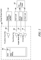
- FIG. 1 is a schematic diagram of an example of an energy storage system 100 for an aircraft.
- the energy storage system 100 may include a battery management system 102 comprising a main battery 104, a propulsion power bus 106, a non-critical bus 108, a critical bus 110, and an engine starter bus 112.
- the non-critical bus 108, the critical bus 110, and the engine starter bus 112 may be at a lower voltage than the propulsion power bus 106.
- the non-critical bus 108, the critical bus 110, and the engine starter bus 112 may be referred to as the low voltage non-critical bus 108, the low voltage critical bus 110, and the low voltage engine starter bus 112, respectively.
- the propulsion power bus 106 may be designed to be operated at 600 volts DC (Direct Current), whereas the non-critical bus 108, the critical bus 110, and the engine starter bus 112 may all be designed to operate at a lower voltage, such as 28 volts or 24 volts DC.
- DC Direct Current
- the non-critical bus 108, the critical bus 110, and the engine starter bus 112 may all be designed to operate at a lower voltage, such as 28 volts or 24 volts DC.
- the propulsion power bus 106 is configured to convey electricity, which is supplied by the main battery 104, to an electric propulsion machine 114.
- the electric propulsion machine 114 is configured to provide propulsion for the aircraft.
- the electric propulsion machine 114 may be configured to power a propulsor, such as a propeller, via a driveshaft and/or a drivetrain that includes a gear box.
- the propulsor may be any mechanical device that provides propulsion for the aircraft.
- the electric propulsion machine 114 may be any electric machine, such as an electric motor or an electric motor/generator, configured to provide propulsion for the aircraft.
- the non-critical bus 108 is configured to convey electricity to a hotel load 116, such as an entertainment system, on the aircraft.
- the critical bus 110 is configured to convey electricity, which may be supplied by the main battery 104, to a critical load 118 on the aircraft.
- the critical load 118 may include an engine control system, a platform control system, avionics, a power electronic drive for a turbogenerator, a controller for a propulsor, a controller for the electric propulsion machine 114, and/or any other electrical system that provides safety functionality or is required for continued safe operation of the aircraft (flight critical).
- the power electronic drive may include a lube oil pump, a cooling water pump, a hydraulic pump, and a fan motor.
- the engine starter bus 112 is configured to convey electricity, which may be supplied by the main battery 104, to an electric starter 120 for a gas turbine engine 122.
- the gas turbine engine 122 is configured to power the electric propulsion machine 114.
- the gas turbine engine 122 may be configured to power an electric generator (not shown), which in turn is configured to provide electric power to the electric propulsion machine 114.
- the combination of the gas turbine engine 122 and the generator may be referred to as a turbogenerator.
- the gas turbine engine 122 may be mechanically coupled to the propulsor that the electric propulsion machine 114 is configured to mechanically power.
- a clutch or a set of clutches may selectively couple the propulsor mechanically to the electric propulsion machine 114 or the gas turbine engine 122.
- the electric starter 120 is different than the electric propulsion machine 114 that powers the propulsor. In addition, the electric starter 120 is different than any generator powered by the gas turbine engine 122 that powers the electric propulsion machine 114. As a result, the engine starter bus 112 and the electric starter 120 provide a mechanism for starting the gas turbine engine 122 even if a failure or a fault occurs on the propulsion power bus 106 or the non-critical bus 108.
- FIG. 2 illustrates a circuit diagram of an example of an electric circuit included in the energy storage system 100 for the aircraft.
- the system 100 illustrated in FIG. 2 includes the battery management system 102, the propulsion power bus 106, a battery charge input 207 to receive a charge from a ground-based charger (not shown), the non-critical bus 108, the engine starter bus 112, and the critical bus 110.
- the system 100 illustrated in FIG. 2 includes the battery management system 102, the propulsion power bus 106, a battery charge input 207 to receive a charge from a ground-based charger (not shown), the non-critical bus 108, the engine starter bus 112, and the critical bus 110.
- first DC-DC converter 202 for the propulsion power bus 106 and the battery charge input 107
- second DC-DC converter 204 for the non-critical bus 108 and the engine starter bus 112
- third DC-DC converter 206 for an energy storage system controller 214 (ESS controller)
- fourth DC-DC converter 208 for the critical bus 110
- fifth DC-DC converter 210 for supplying backup battery power to the ESS controller 214
- sixth DC-DC converter 212 for supplying backup battery power to the critical bus 110
- two corresponding backup batteries 216 and 218 includes a first DC-DC converter 202 for the propulsion power bus 106 and the battery charge input 107
- second DC-DC converter 204 for the non-critical bus 108 and the engine starter bus 112
- third DC-DC converter 206 for an energy storage system controller 214 (ESS controller)
- fourth DC-DC converter 208 for the critical bus 110
- fifth DC-DC converter 210 for supplying backup battery power to the ESS controller 214
- sixth DC-DC converter 212 for supplying backup
- the first DC-DC converter 202 may be configured to convert a DC power signal from the main battery 104 to a predetermined target voltage on the propulsion power bus 106.
- the predetermined target voltage may be a fixed voltage such as 600 volts or any other voltage suitable to power the electric propulsion machine 114.
- the DC-DC converter 202 may be configured to convert a DC power signal received on the battery charge input 207 to a voltage suitable for charging the main battery 104.
- the second DC-DC converter 204 may be configured to convert a DC power signal from the main battery 104 to a predetermined target voltage on the non-critical bus 108 and/or the engine starter bus 112.
- the predetermined target voltage may be a fixed voltage such as 28 volts or any other voltage suitable to power the electric starter 120 and/or the hotel load 116.
- the second DC-DC converter 204 may supply the converted DC power signal selectively to the non-critical bus 108, the engine starter bus 112, or both depending on the manner in which the ESS controller 214 controls the contactors or the switches.
- the system 100 may include a DC-DC convertor for the non-critical bus 108 and another DC-DC converter for the engine starter bus 112 instead of the two busses sharing the second DC-DC converter 204.
- the third DC-DC converter 206 may be configured to convert a DC power signal from the main battery 104 to a predetermined target voltage for the energy storage system controller 214.
- the predetermined target voltage may be a fixed voltage such as 24 volts or any other voltage suitable to power the ESS controller 214 over a line 220, which may also be referred to as an internal energy storage control bus.
- the fourth DC-DC converter 208 may be configured to convert a DC power signal from the main battery 104 to a predetermined target voltage for the critical bus 110.
- the predetermined target voltage may be a fixed voltage such as 24 volts or any other voltage suitable to power the critical load 118.
- the fifth DC-DC converter 210 may be configured to supply power from the first backup battery 216 to the ESS controller 214 if the voltage on the line 220 to power the ESS controller 214 drops below a threshold voltage, such as 22 volts, for example.
- the threshold voltage may be less than or equal to the predetermined target voltage that the third DC-DC converter 206 targets on the line 220 to the ESS controller 214. If the voltage on the line 220 drops below the threshold voltage, it may be an indication that the main battery 104 is failing to provide adequate power to the ESS controller 214 and/or the main battery 104 has not yet been started and is not yet able to provide adequate power to the ESS controller 214.
- the first backup battery 216 may supply power to the ESS controller 214 via the fifth DC-DC converter 210.
- the first backup battery 216 may also be referred to as a control battery.
- the control battery may not be expected to provide power once the main battery 104 is started or initialized.
- the sixth DC-DC converter 212 may be configured to supply power from the second backup battery 218 to the critical bus 110 if the voltage on the critical bus 110 drops below a threshold voltage, such as 22 volts.
- the threshold voltage may be less than or equal to the predetermined target voltage that the fourth DC-DC converter 208 targets on the critical bus 110. If the voltage on the critical bus 110 drops below the threshold voltage, it may be an indication that the main battery 104 is failing to provide adequate power to the critical bus 110 and/or the main battery 104 has not yet been started and is not yet able to provide adequate power to the critical bus 110. In such a scenario, the second backup battery 218 may supply power to the critical bus 110 via the sixth DC-DC converter 212.
- the second DC-DC converter 204, the third DC-DC converter 206, the fourth DC-DC converter 208, the fifth DC-DC converter 210, and the sixth DC-DC converter may be isolated DC-DC converters.
- An isolated DC-DC converter is a converter in which an input of the converter is electrically isolated from an output of the converter.
- the isolated DC-DC converter may include a transformer that isolates the input from the output.
- Examples of isolated DC/DC converters may include regulated, unregulated, and semi-regulated converters.
- the isolated DC-DC converter may include a feedback circuit that enables the converter to generate a target voltage at the output of the converter.
- the main battery 104 may comprise a battery pack, a lithium ion battery, a lithium ion battery stack, a supercapacitor, a fuel cell system, an electrochemical cell, a lithium-metal battery, a lithium-air battery, and/or any other type of battery or combination of batteries.
- the battery management system 102 may include a controller interface (not shown) through which the ESS controller 214 may control the main battery 104.
- Each of the backup batteries 216 and 218 may include a lead acid battery, a lithium ion battery, and/or any other type of battery or combination of batteries.
- the ESS controller 214 may include an application specific integrated circuit (ASIC), a digital signal processor, a field programmable gate array (FPGA), a digital circuit, an analog circuit, a controller, a microcontroller, a computing device, any other type of processor, or any combination thereof.
- ASIC application specific integrated circuit
- FPGA field programmable gate array
- the ESS controller 214 includes at least some hardware even if the included hardware comprises software.
- the electric starter 120 may include any electric machine configured to mechanically rotate a rotor of the gas turbine engine 122. In some examples, the electric starter 120 may also operate as a generator, and may generate power for non-critical bus 108 after the gas turbine engine 122 starts up.
- the gas turbine engine 122 may take a variety of forms in various embodiments.
- the gas turbine engine 122 may be an axial flow engine.
- the gas turbine engine 122 may have multiple spools and/or may be a centrifugal or mixed centrifugal/axial flow engine.
- the gas turbine engine 122 may be a turboprop, a turbofan, or a turboshaft engine.
- the gas turbine engine 122 may be an adaptive cycle and/or variable cycle engine. Other variations are also contemplated.
- the gas turbine engine 122 may include, for example, an intake section, a compressor section, a combustion section, a turbine section, and an exhaust section.
- fluid received from the intake section such as air
- the compressed fluid may then be mixed with fuel and the mixture may be burned in the combustion section.
- the combustion section may include any suitable fuel injection and combustion mechanisms.
- the hot, high pressure fluid may then pass through the turbine section to extract energy from the fluid and cause a turbine shaft of a turbine in the turbine section to rotate, which in turn drives the compressor section.
- Discharge fluid may exit the exhaust section.
- the hot, high pressure fluid passes through the turbine section during operation of the gas turbine engine 122.
- the fluid passes between adjacent blades of the turbine causing the turbine to rotate.
- the rotating turbine may turn a shaft that powers the compressor.
- Examples of the aircraft may include a helicopter, an airplane, an unmanned space vehicle, a fixed wing vehicle, a variable wing vehicle, a rotary wing vehicle, an unmanned combat aerial vehicle, a tailless aircraft, a hover craft, and any other airborne and/or extraterrestrial (spacecraft) vehicle.
- a helicopter an airplane, an unmanned space vehicle, a fixed wing vehicle, a variable wing vehicle, a rotary wing vehicle, an unmanned combat aerial vehicle, a tailless aircraft, a hover craft, and any other airborne and/or extraterrestrial (spacecraft) vehicle.
- the system 100 may be implemented in many different ways.
- the system 100 may include additional, fewer, and/or different components than illustrated.
- the system 100 may include a single backup battery that may be used to provide backup power to the critical bus 110 and the ESS controller 214.
- a single DC-DC converter may replace the fifth and sixth DC-DC converters 210 and 212.
- a single bus may serve as both the battery charge input 107 and the propulsion power bus 106.
- the system 100 may include additional switches, contacts, fuses, and/or other electrical components than shown in FIGS 1 and 2 .
- the propulsion power bus 106 may be designed as a variable voltage bus instead of a fixed voltage bus.
- the system 100 may include one or more built-in absence of voltage meters (AVMs).
- AVMs built-in absence of voltage meters
- the AVM may indicate to personnel interacting with the system 100 whether any bus, in particular, the propulsion power bus 106, is live and, therefore, may be a safety concern.
- the electric circuit of the system 100 may include a connection between the built-in AVM and the propulsion power bus 106.
- FIG. 3 illustrates a flow diagram of example operations performed by the energy storage system 100.
- the operations may include additional, different, or fewer operations than illustrated in FIG. 3 .
- the steps may be executed in a different order than illustrated in FIG. 3 .
- Operation may begin by supplying (302) electrical power from the main battery 104 to the electric propulsion machine 114 of the aircraft via the propulsion power bus 106.
- the electric propulsion machine 114 provides propulsion for the aircraft and the electric propulsion machine 114 is alternatively powered by the gas turbine engine 122.
- electrical power may be supplied (304) from the main battery 104 to the hotel load 116 on the aircraft via the non-critical bus 108.
- electrical power may be supplied (306) from the main battery 104 to the critical load 118 on the aircraft over the critical bus 110.
- the gas turbine engine 122 may be started (310) by providing electrical power from the main battery 104 to the electric starter 120 via the engine starter bus 112.
- the gas turbine engine 122 may power the electric propulsion machine 114 after the gas turbine engine 122 is started.
- the gas turbine engine 122 may power a generator that generates electricity for the electric propulsion machine 114.
- operations may continue by, for example, supplying (302) electrical power from the main battery 104 to the electric propulsion machine 114 of the aircraft via the propulsion power bus 106.
- the phrases "at least one of ⁇ A>, ⁇ B>, ... and ⁇ N>” or “at least one of ⁇ A>, ⁇ B>, ... ⁇ N>, or combinations thereof or " ⁇ A>, ⁇ B>, ... and/or ⁇ N>” are defined by the Applicant in the broadest sense, superseding any other implied definitions hereinbefore or hereinafter unless expressly asserted by the Applicant to the contrary, to mean one or more elements selected from the group comprising A, B, ... and N. In other words, the phrases mean any combination of one or more of the elements A, B, ...
Landscapes
- Engineering & Computer Science (AREA)
- Aviation & Aerospace Engineering (AREA)
- Power Engineering (AREA)
- Chemical & Material Sciences (AREA)
- Combustion & Propulsion (AREA)
- Mechanical Engineering (AREA)
- General Engineering & Computer Science (AREA)
- Charge And Discharge Circuits For Batteries Or The Like (AREA)
Abstract
Description
- This disclosure relates to aerospace propulsion systems and, in particular, to aerospace hybrid power systems.
- Present hybrid aerospace propulsion systems suffer from a variety of drawbacks, limitations, and disadvantages. Accordingly, there is a need for inventive systems, methods, components, and apparatuses described herein.
- In one aspect, an energy storage system for an aircraft is provided. The energy storage system includes a main battery, a propulsion power bus, a non-critical bus, a critical bus, and an engine starter bus. The propulsion power bus is configured to convey electricity, which is supplied by the main battery, to an electric propulsion machine configured to provide propulsion for the aircraft. The non-critical bus is configured to convey electricity to a hotel load on the aircraft. The critical bus is configured to convey electricity, which is supplied by the main battery, to a critical load on the aircraft. The engine starter bus is configured to convey electricity, which is supplied by the main battery, to an electric starter for a gas turbine engine. The gas turbine engine is configured to power the electric propulsion machine.
- The energy storage system (ESS) may avoid faulted devices on other buses impacting the delivery of power to critical loads, protection devices, isolators, and contactors, an ability to be recharged from the propulsion power bus, and/or an ability to be charged from ground.
- In some embodiments, the energy storage system further includes an isolated DC-DC converter configured to transform a power signal from the main battery to a target fixed voltage on the engine starter bus.
- In some embodiments, the energy storage system further includes a DC-DC converter configured to transform a power signal from the main battery to a target fixed voltage on the propulsion power bus.
- In some embodiments, the energy storage system further includes an energy storage system controller, a first isolated DC-DC converter, a second isolated DC-DC converter, a first backup battery, and a second backup battery. The first isolated DC-DC converter is configured to supply power from the first backup battery to the energy storage system controller. The second isolated DC-DC converter is configured to supply power from the second backup battery to the critical bus.
- In some embodiments, the energy storage system further includes an isolated DC-DC converter configured to transform a power signal from the main battery to a target voltage on the critical bus.
- In some embodiments, the main battery includes a lithium ion battery.
- In some embodiments, each of the first backup battery and the second backup battery includes one or more of a lead acid battery and a lithium ion battery.
- In some embodiments, the propulsion power bus is a fixed voltage bus or a variable voltage bus.
- In another aspect, an electric circuit of an energy storage system is provided. The electric circuit includes a propulsion power bus, a non-critical bus, a critical bus, and an engine starter bus. The propulsion power bus is configured to provide a power signal from a main battery to an electric propulsion machine. The electric propulsion machine is configured to power a propulsor for an aircraft. The electric propulsion machine is further configured to be powered by a gas turbine engine. The non-critical bus is configured to provide electric power to a hotel load on the aircraft. The critical bus is configured to provide electric power supplied by the main battery to a critical load on the aircraft. The engine starter bus is configured to provide electricity supplied by the main battery to an electric starter. The electric starter is configured to startup the gas turbine engine.
- In some embodiments, the electric circuit further includes an isolated DC-DC converter configured to transform a power signal from the main battery to a target fixed voltage on the engine starter bus.
- In some embodiments, the electric circuit further includes a DC-DC converter configured to transform a power signal from the main battery to a target fixed voltage on the propulsion power bus.
- In some embodiments, the electric circuit further includes an energy storage system controller, a first isolated DC-DC converter, a second isolated DC-DC converter, a first backup battery, and a second backup battery. The first isolated DC-DC converter is configured to supply power from the first backup battery to the energy storage system controller. The second isolated DC-DC converter is configured to supply power from the second backup battery to the critical bus.
- In some embodiments, the electric circuit further includes a controller and an isolated DC-DC converter. The controller is configured to control the main battery and the isolated DC-DC converter is configured to supply power from the main battery to the controller.
- In some embodiments, the electric circuit further includes an isolated DC-DC converter configured to transform a power signal from the main battery to a target voltage on the critical bus.
- In some embodiments, the main battery includes a lithium ion battery.
- In another aspect, there is provided a method including supplying electrical power from a battery to an electric propulsion machine of an aircraft via a propulsion power bus. The electric propulsion machine provides propulsion for the aircraft and the electric propulsion machine is alternatively powered by a gas turbine engine. The method further includes supplying electrical power from the battery to a hotel load on the aircraft via a non-critical bus. The method further includes supplying electrical power from the battery to a critical load on the aircraft over a critical bus. The method further includes starting the gas turbine engine by providing electrical power from the battery to an electric starter via an engine starter bus. The gas turbine engine powers the electric propulsion machine after the gas turbine engine is started.
- In some embodiments, the method further includes transforming a power signal from the battery to a target fixed voltage on the engine starter bus.
- In some embodiments, the method further includes transforming a power signal from the battery to a target fixed voltage on the propulsion power bus.
- In some embodiments, the method further includes supplying power from a first backup battery to an energy storage system controller via a first isolated DC-DC converter, and supplying power from a second backup battery to the critical bus via a second isolated DC-DC converter.
- In some embodiments, the method further includes controlling the battery with a controller that is powered by the battery via an isolated DC-DC converter.
- In some embodiments, the method further includes transforming a power signal from the battery to a target fixed voltage on the critical bus.
- The embodiments may be better understood with reference to the following drawings and description. The components in the figures are not necessarily to scale. Moreover, in the figures, like-referenced numerals designate corresponding parts throughout the different views.
-
FIG. 1 is a schematic diagram of an example of an energy storage system for an aircraft; -
FIG. 2 illustrates a circuit diagram of an example of an electric circuit included in an energy storage system; and -
FIG. 3 illustrates a flow diagram of example operations performed by an energy storage system. - In one example, an energy storage system for an aircraft is provided. The energy storage system includes a main battery, a propulsion power bus, a non-critical bus, a critical bus, and an engine starter bus. The propulsion power bus is configured to convey electricity, which is supplied by the main battery, to an electric propulsion machine configured to provide propulsion for the aircraft. The non-critical bus is configured to convey electricity to a hotel load on the aircraft, such as an entertainment system. The critical bus is configured to convey electricity, which is supplied by the main battery, to a critical load on the aircraft, such as avionics. The engine starter bus is configured to convey electricity, which is supplied by the main battery, to an electric starter for a gas turbine engine, where the gas turbine engine is configured to power the electric propulsion machine. The energy storage system, together with the engine starter and the gas turbine engine, make up a hybrid propulsion system for the aircraft.
- In a second example, an electric circuit of an energy storage system is provided. The electric circuit includes a propulsion power bus, a non-critical bus, a critical bus, and an engine starter bus. The propulsion power bus is configured to provide a power signal from a main battery to an electric propulsion machine. The electric propulsion machine is configured to power a propulsor for an aircraft. The electric propulsion machine is further configured to be powered by a gas turbine engine. The non-critical bus is configured to provide electric power to a hotel load on the aircraft. The critical bus is configured to provide electric power supplied by the main battery to a critical load on the aircraft. The engine starter bus is configured to provide electricity supplied by the main battery to an electric starter, the electric starter is configured to startup the gas turbine engine.
- In a third example, a method of operation is provided. Electrical power is supplied from a battery to an electric propulsion machine of an aircraft via a propulsion power bus. The electric propulsion machine provides propulsion for the aircraft and the electric propulsion machine is alternatively powered by a gas turbine engine. Electrical power is supplied from the battery to a hotel load on the aircraft via a non-critical bus. Electrical power is supplied from the battery to a critical load on the aircraft over a critical bus. The gas turbine engine may be started by providing electrical power from the battery to an electric starter via an engine starter bus, where the gas turbine engine powers the electric propulsion machine after the gas turbine engine is started.
- The energy storage system (ESS) is for an aerospace application, and may supply output power to: a hybrid propulsion bus delivering power to a number of motor driven propulsors; a low voltage critical bus delivering power to engine and/or platform control systems, avionics, power electronic drive(s) for turbogenerator(s) and electric motor drive(s) for propulsors; a low voltage supply for non-critical loads, such as entertainment systems; a low voltage high current mode to deliver starting power for a turbogenerator. The EES may provide, for example, cell battery management system(s), a controller interface, electrical and thermal isolation between the low voltage buses and other buses to avoid faulted devices on other buses impacting the delivery of power to critical loads, protection devices, isolators, and contactors, an ability to be recharged from the propulsion bus, and/or an ability to be charged from ground.
-
FIG. 1 is a schematic diagram of an example of anenergy storage system 100 for an aircraft. Theenergy storage system 100 may include abattery management system 102 comprising amain battery 104, apropulsion power bus 106, anon-critical bus 108, acritical bus 110, and anengine starter bus 112. Thenon-critical bus 108, thecritical bus 110, and theengine starter bus 112 may be at a lower voltage than thepropulsion power bus 106. For that reason, thenon-critical bus 108, thecritical bus 110, and theengine starter bus 112 may be referred to as the low voltagenon-critical bus 108, the low voltagecritical bus 110, and the low voltageengine starter bus 112, respectively. For example, thepropulsion power bus 106 may be designed to be operated at 600 volts DC (Direct Current), whereas thenon-critical bus 108, thecritical bus 110, and theengine starter bus 112 may all be designed to operate at a lower voltage, such as 28 volts or 24 volts DC. - The
propulsion power bus 106 is configured to convey electricity, which is supplied by themain battery 104, to anelectric propulsion machine 114. Theelectric propulsion machine 114 is configured to provide propulsion for the aircraft. For example, theelectric propulsion machine 114 may be configured to power a propulsor, such as a propeller, via a driveshaft and/or a drivetrain that includes a gear box. The propulsor may be any mechanical device that provides propulsion for the aircraft. Theelectric propulsion machine 114 may be any electric machine, such as an electric motor or an electric motor/generator, configured to provide propulsion for the aircraft. - The
non-critical bus 108 is configured to convey electricity to ahotel load 116, such as an entertainment system, on the aircraft. In contrast, thecritical bus 110 is configured to convey electricity, which may be supplied by themain battery 104, to acritical load 118 on the aircraft. Examples of thecritical load 118 may include an engine control system, a platform control system, avionics, a power electronic drive for a turbogenerator, a controller for a propulsor, a controller for theelectric propulsion machine 114, and/or any other electrical system that provides safety functionality or is required for continued safe operation of the aircraft (flight critical). Examples of the power electronic drive may include a lube oil pump, a cooling water pump, a hydraulic pump, and a fan motor. - The
engine starter bus 112 is configured to convey electricity, which may be supplied by themain battery 104, to anelectric starter 120 for agas turbine engine 122. Thegas turbine engine 122 is configured to power theelectric propulsion machine 114. For example, thegas turbine engine 122 may be configured to power an electric generator (not shown), which in turn is configured to provide electric power to theelectric propulsion machine 114. In such an example, the combination of thegas turbine engine 122 and the generator may be referred to as a turbogenerator. Alternatively or in addition, thegas turbine engine 122 may be mechanically coupled to the propulsor that theelectric propulsion machine 114 is configured to mechanically power. For example, a clutch or a set of clutches may selectively couple the propulsor mechanically to theelectric propulsion machine 114 or thegas turbine engine 122. - The
electric starter 120 is different than theelectric propulsion machine 114 that powers the propulsor. In addition, theelectric starter 120 is different than any generator powered by thegas turbine engine 122 that powers theelectric propulsion machine 114. As a result, theengine starter bus 112 and theelectric starter 120 provide a mechanism for starting thegas turbine engine 122 even if a failure or a fault occurs on thepropulsion power bus 106 or thenon-critical bus 108. -
FIG. 2 illustrates a circuit diagram of an example of an electric circuit included in theenergy storage system 100 for the aircraft. Thesystem 100 illustrated inFIG. 2 includes thebattery management system 102, thepropulsion power bus 106, abattery charge input 207 to receive a charge from a ground-based charger (not shown), thenon-critical bus 108, theengine starter bus 112, and thecritical bus 110. In addition, thesystem 100 illustrated inFIG. 2 includes a first DC-DC converter 202 for thepropulsion power bus 106 and the battery charge input 107, a second DC-DC converter 204 for thenon-critical bus 108 and theengine starter bus 112, a third DC-DC converter 206 for an energy storage system controller 214 (ESS controller), a fourth DC-DC converter 208 for thecritical bus 110, a fifth DC-DC converter 210 for supplying backup battery power to theESS controller 214, a sixth DC-DC converter 212 for supplying backup battery power to thecritical bus 110, and two correspondingbackup batteries - The first DC-
DC converter 202 may be configured to convert a DC power signal from themain battery 104 to a predetermined target voltage on thepropulsion power bus 106. The predetermined target voltage may be a fixed voltage such as 600 volts or any other voltage suitable to power theelectric propulsion machine 114. In addition, the DC-DC converter 202 may be configured to convert a DC power signal received on thebattery charge input 207 to a voltage suitable for charging themain battery 104. - The second DC-
DC converter 204 may be configured to convert a DC power signal from themain battery 104 to a predetermined target voltage on thenon-critical bus 108 and/or theengine starter bus 112. The predetermined target voltage may be a fixed voltage such as 28 volts or any other voltage suitable to power theelectric starter 120 and/or thehotel load 116. By including contactors or switches in thesystem 100, the second DC-DC converter 204 may supply the converted DC power signal selectively to thenon-critical bus 108, theengine starter bus 112, or both depending on the manner in which theESS controller 214 controls the contactors or the switches. In alternative examples, thesystem 100 may include a DC-DC convertor for thenon-critical bus 108 and another DC-DC converter for theengine starter bus 112 instead of the two busses sharing the second DC-DC converter 204. - The third DC-
DC converter 206 may be configured to convert a DC power signal from themain battery 104 to a predetermined target voltage for the energystorage system controller 214. The predetermined target voltage may be a fixed voltage such as 24 volts or any other voltage suitable to power theESS controller 214 over aline 220, which may also be referred to as an internal energy storage control bus. - The fourth DC-
DC converter 208 may be configured to convert a DC power signal from themain battery 104 to a predetermined target voltage for thecritical bus 110. The predetermined target voltage may be a fixed voltage such as 24 volts or any other voltage suitable to power thecritical load 118. - The fifth DC-
DC converter 210 may be configured to supply power from thefirst backup battery 216 to theESS controller 214 if the voltage on theline 220 to power theESS controller 214 drops below a threshold voltage, such as 22 volts, for example. The threshold voltage may be less than or equal to the predetermined target voltage that the third DC-DC converter 206 targets on theline 220 to theESS controller 214. If the voltage on theline 220 drops below the threshold voltage, it may be an indication that themain battery 104 is failing to provide adequate power to theESS controller 214 and/or themain battery 104 has not yet been started and is not yet able to provide adequate power to theESS controller 214. In such a scenario, thefirst backup battery 216 may supply power to theESS controller 214 via the fifth DC-DC converter 210. Thefirst backup battery 216 may also be referred to as a control battery. The control battery may not be expected to provide power once themain battery 104 is started or initialized. - The sixth DC-
DC converter 212 may be configured to supply power from thesecond backup battery 218 to thecritical bus 110 if the voltage on thecritical bus 110 drops below a threshold voltage, such as 22 volts. The threshold voltage may be less than or equal to the predetermined target voltage that the fourth DC-DC converter 208 targets on thecritical bus 110. If the voltage on thecritical bus 110 drops below the threshold voltage, it may be an indication that themain battery 104 is failing to provide adequate power to thecritical bus 110 and/or themain battery 104 has not yet been started and is not yet able to provide adequate power to thecritical bus 110. In such a scenario, thesecond backup battery 218 may supply power to thecritical bus 110 via the sixth DC-DC converter 212. - The second DC-
DC converter 204, the third DC-DC converter 206, the fourth DC-DC converter 208, the fifth DC-DC converter 210, and the sixth DC-DC converter may be isolated DC-DC converters. An isolated DC-DC converter is a converter in which an input of the converter is electrically isolated from an output of the converter. For example, the isolated DC-DC converter may include a transformer that isolates the input from the output. Examples of isolated DC/DC converters may include regulated, unregulated, and semi-regulated converters. The isolated DC-DC converter may include a feedback circuit that enables the converter to generate a target voltage at the output of the converter. - The
main battery 104 may comprise a battery pack, a lithium ion battery, a lithium ion battery stack, a supercapacitor, a fuel cell system, an electrochemical cell, a lithium-metal battery, a lithium-air battery, and/or any other type of battery or combination of batteries. Thebattery management system 102 may include a controller interface (not shown) through which theESS controller 214 may control themain battery 104. Each of thebackup batteries - The
ESS controller 214 may include an application specific integrated circuit (ASIC), a digital signal processor, a field programmable gate array (FPGA), a digital circuit, an analog circuit, a controller, a microcontroller, a computing device, any other type of processor, or any combination thereof. TheESS controller 214 includes at least some hardware even if the included hardware comprises software. - The
electric starter 120 may include any electric machine configured to mechanically rotate a rotor of thegas turbine engine 122. In some examples, theelectric starter 120 may also operate as a generator, and may generate power fornon-critical bus 108 after thegas turbine engine 122 starts up. - The
gas turbine engine 122 may take a variety of forms in various embodiments. For example, thegas turbine engine 122 may be an axial flow engine. Thegas turbine engine 122 may have multiple spools and/or may be a centrifugal or mixed centrifugal/axial flow engine. In some forms, thegas turbine engine 122 may be a turboprop, a turbofan, or a turboshaft engine. Furthermore, thegas turbine engine 122 may be an adaptive cycle and/or variable cycle engine. Other variations are also contemplated. - The
gas turbine engine 122 may include, for example, an intake section, a compressor section, a combustion section, a turbine section, and an exhaust section. During operation of thegas turbine engine 122, fluid received from the intake section, such as air, may be compressed within the compressor section. The compressed fluid may then be mixed with fuel and the mixture may be burned in the combustion section. The combustion section may include any suitable fuel injection and combustion mechanisms. The hot, high pressure fluid may then pass through the turbine section to extract energy from the fluid and cause a turbine shaft of a turbine in the turbine section to rotate, which in turn drives the compressor section. Discharge fluid may exit the exhaust section. - As noted above, the hot, high pressure fluid passes through the turbine section during operation of the
gas turbine engine 122. As the fluid flows through the turbine section, the fluid passes between adjacent blades of the turbine causing the turbine to rotate. The rotating turbine may turn a shaft that powers the compressor. - Examples of the aircraft may include a helicopter, an airplane, an unmanned space vehicle, a fixed wing vehicle, a variable wing vehicle, a rotary wing vehicle, an unmanned combat aerial vehicle, a tailless aircraft, a hover craft, and any other airborne and/or extraterrestrial (spacecraft) vehicle.
- The
system 100 may be implemented in many different ways. Thesystem 100 may include additional, fewer, and/or different components than illustrated. For example, instead of having the first and secondbackup batteries system 100 may include a single backup battery that may be used to provide backup power to thecritical bus 110 and theESS controller 214. In such an example, a single DC-DC converter may replace the fifth and sixth DC-DC converters propulsion power bus 106, a single bus may serve as both the battery charge input 107 and thepropulsion power bus 106. In still another example, thesystem 100 may include additional switches, contacts, fuses, and/or other electrical components than shown inFIGS 1 and2 . Alternatively or in addition, in some examples, thepropulsion power bus 106 may be designed as a variable voltage bus instead of a fixed voltage bus. In some examples, thesystem 100 may include one or more built-in absence of voltage meters (AVMs). By including a built-in AVM, the AVM may indicate to personnel interacting with thesystem 100 whether any bus, in particular, thepropulsion power bus 106, is live and, therefore, may be a safety concern. For example, the electric circuit of thesystem 100 may include a connection between the built-in AVM and thepropulsion power bus 106. -
FIG. 3 illustrates a flow diagram of example operations performed by theenergy storage system 100. The operations may include additional, different, or fewer operations than illustrated inFIG. 3 . The steps may be executed in a different order than illustrated inFIG. 3 . - Operation may begin by supplying (302) electrical power from the
main battery 104 to theelectric propulsion machine 114 of the aircraft via thepropulsion power bus 106. Theelectric propulsion machine 114 provides propulsion for the aircraft and theelectric propulsion machine 114 is alternatively powered by thegas turbine engine 122. - Concurrently, electrical power may be supplied (304) from the
main battery 104 to thehotel load 116 on the aircraft via thenon-critical bus 108. - In addition, electrical power may be supplied (306) from the
main battery 104 to thecritical load 118 on the aircraft over thecritical bus 110. - If a startup of the
gas turbine engine 122 is determined (308) to be needed because, for example, a charge level of themain battery 104 drops below a threshold level, then thegas turbine engine 122 may be started (310) by providing electrical power from themain battery 104 to theelectric starter 120 via theengine starter bus 112. Thegas turbine engine 122 may power theelectric propulsion machine 114 after thegas turbine engine 122 is started. For example, thegas turbine engine 122 may power a generator that generates electricity for theelectric propulsion machine 114. - Alternatively, if the startup of the
gas turbine engine 122 is not needed, then operations may continue by, for example, supplying (302) electrical power from themain battery 104 to theelectric propulsion machine 114 of the aircraft via thepropulsion power bus 106. - To clarify the use of and to hereby provide notice to the public, the phrases "at least one of <A>, <B>, ... and <N>" or "at least one of <A>, <B>, ... <N>, or combinations thereof or "<A>, <B>, ... and/or <N>" are defined by the Applicant in the broadest sense, superseding any other implied definitions hereinbefore or hereinafter unless expressly asserted by the Applicant to the contrary, to mean one or more elements selected from the group comprising A, B, ... and N. In other words, the phrases mean any combination of one or more of the elements A, B, ... or N including any one element alone or the one element in combination with one or more of the other elements which may also include, in combination, additional elements not listed. Unless otherwise indicated or the context suggests otherwise, as used herein, "a" or "an" means "at least one" or "one or more."
- While various embodiments have been described, it will be apparent to those of ordinary skill in the art that many more embodiments and implementations are possible. Accordingly, the embodiments described herein are examples, not the only possible embodiments and implementations.
Claims (15)
- An energy storage system (100) for an aircraft, the energy storage system (100) comprising:a main battery (104);a propulsion power bus (106) configured to convey electricity, which is supplied by the main battery (104), to an electric propulsion machine (114) configured to provide propulsion for the aircraft;a non-critical bus (108) configured to convey electricity to a hotel load (116) on the aircraft;a critical bus (110) configured to convey electricity, which is supplied by the main battery (104), to a critical load (118) on the aircraft; andan engine starter bus (112) configured to convey electricity, which is supplied by the main battery (104), to an electric starter (120) for a gas turbine engine (122), wherein the gas turbine engine (122) is configured to power the electric propulsion machine (114).
- The energy storage system (100) of claim 1 further comprising an isolated DC-DC converter (204) configured to transform a power signal from the main battery (104) to a target fixed voltage on the engine starter bus (112).
- The energy storage system (100) of claim 1 or 2 further comprising a DC-DC converter (202) configured to transform a power signal from the main battery (104) to a target fixed voltage on the propulsion power bus (106).
- The energy storage system (100) of any one of claims 1 to 3 further comprising an energy storage system controller (214), a first isolated DC-DC converter (210), a second isolated DC-DC converter (212), a first backup battery (216), and a second backup battery (218), wherein the first isolated DC-DC converter (210) is configured to supply power from the first backup battery (216) to the energy storage system controller (214), and wherein the second isolated DC-DC converter (212) is configured to supply power from the second backup battery (218) to the critical bus (110).
- The energy storage system (100) of any one of claims 1 to 4 further comprising a controller (214) and an isolated DC-DC converter (206), the controller (214) configured to control the main battery (104) and the isolated DC-DC converter (206) configured to supply power from the main battery (104) to the controller (214).
- The energy storage system (100) of any one of claims 1 to 5 further comprising an isolated DC-DC (208) converter configured to transform a power signal from the main battery (104) to a target voltage on the critical bus (110).
- The energy storage system (100) of any one of claims 1 to 6, wherein the main battery (104) comprises a lithium ion battery.
- The energy storage system (100) of any one of claims 4 to 7, wherein each of the first backup battery (216) and the second backup battery (218) comprises one or more of a lead acid battery and a lithium ion battery.
- The energy storage system (100) of claim 1, wherein the propulsion power bus (106) is a fixed voltage bus or a variable voltage bus.
- A method comprising:supplying (302) electrical power from a battery (104) to an electric propulsion machine (114) of an aircraft via a propulsion power bus (106), wherein the electric propulsion machine (114) provides propulsion for the aircraft and the electric propulsion machine (114) is alternatively powered by a gas turbine engine (122);supplying (304) electrical power from the battery (104) to a hotel load (116) on the aircraft via a non-critical bus (108);supplying (306) electrical power from the battery (104) to a critical load (118) on the aircraft over a critical bus (110); andstarting (310) the gas turbine engine (122) by providing electrical power from the battery (104) to an electric starter (120) via an engine starter bus (112), wherein the gas turbine engine (122) powers the electric propulsion machine (114) after the gas turbine engine (122) is started.
- The method of claim 10 further comprising transforming a power signal from the battery (104) to a target fixed voltage on the engine starter bus (112).
- The method of claim 10 further comprising transforming a power signal from the battery (104) to a target fixed voltage on the propulsion power bus (106).
- The method of any one of claims 10 to 12 further comprising supplying power from a first backup battery (216) to an energy storage system controller (214) via a first isolated DC-DC converter (210), and supplying power from a second backup battery (218) to the critical bus (110) via a second isolated DC-DC converter (212) .
- The method of any one of claims 10 to13 further comprising controlling the battery (104) with a controller (214) that is powered by the battery (104) via an isolated DC-DC converter (206).
- The method of claim 10 further comprising transforming a power signal from the battery (104) to a target fixed voltage on the critical bus (110).
Applications Claiming Priority (1)
| Application Number | Priority Date | Filing Date | Title |
|---|---|---|---|
| US16/180,570 US10906658B2 (en) | 2018-11-05 | 2018-11-05 | Energy storage system for a hybrid power system |
Publications (2)
| Publication Number | Publication Date |
|---|---|
| EP3648278A1 true EP3648278A1 (en) | 2020-05-06 |
| EP3648278B1 EP3648278B1 (en) | 2024-08-28 |
Family
ID=68137897
Family Applications (1)
| Application Number | Title | Priority Date | Filing Date |
|---|---|---|---|
| EP19201278.9A Active EP3648278B1 (en) | 2018-11-05 | 2019-10-03 | Energy storage system for a hybrid power system |
Country Status (3)
| Country | Link |
|---|---|
| US (1) | US10906658B2 (en) |
| EP (1) | EP3648278B1 (en) |
| CA (1) | CA3054884A1 (en) |
Families Citing this family (11)
| Publication number | Priority date | Publication date | Assignee | Title |
|---|---|---|---|---|
| CN115133612B (en) * | 2019-07-09 | 2025-11-07 | 华为数字能源技术有限公司 | Power supply circuit and uninterruptible power supply UPS system |
| CN113437742B (en) * | 2021-07-20 | 2025-10-17 | 中国商用飞机有限责任公司北京民用飞机技术研究中心 | Power supply method and system for hybrid aircraft |
| US11901758B2 (en) | 2021-09-14 | 2024-02-13 | General Electric Company | Loading sharing across multiple power supplies |
| EP4148934A3 (en) | 2021-09-14 | 2023-03-29 | General Electric Company | Loading sharing across multiple power supplies |
| US12297771B2 (en) | 2022-07-08 | 2025-05-13 | Rolls-Royce Corporation | Energy storage system heater control architecture |
| SE545936C2 (en) * | 2022-07-29 | 2024-03-19 | Heart Aerospace AB | An energy distribution system |
| US12567613B2 (en) | 2022-08-25 | 2026-03-03 | Rolls-Royce Corporation | Aircraft thermal management system for an energy storage system |
| SE546663C2 (en) * | 2022-09-13 | 2025-01-14 | Heart Aerospace AB | A system and method for charging an airplane |
| US12098695B1 (en) | 2023-07-28 | 2024-09-24 | Rolls-Royce Corporation | Bus bar interconnect for low voltage battery start of gas-turbine engine |
| GB202315703D0 (en) * | 2023-10-13 | 2023-11-29 | Rolls Royce Plc | Dc:dc converter |
| US12570229B2 (en) * | 2024-08-16 | 2026-03-10 | Aptiv Technologies AG | Electrical power distribution system with selectively connectable charge storage medium |
Citations (5)
| Publication number | Priority date | Publication date | Assignee | Title |
|---|---|---|---|---|
| US20090302153A1 (en) * | 2008-06-10 | 2009-12-10 | Lockheed Martin Corporation | Electrical system and electrical accumulator for electrical actuation and related methods |
| US20160036220A1 (en) * | 2014-08-01 | 2016-02-04 | Thales | Electrical network of an aircraft |
| EP3044846A1 (en) * | 2013-09-09 | 2016-07-20 | GE Aviation Systems LLC | Power system for an aircraft with dual hybrid energy sources |
| US20160236790A1 (en) * | 2014-08-29 | 2016-08-18 | Tzunum, Inc. | System and methods for implementing regional air transit network using hybrid-electric aircraft |
| US20170274847A1 (en) * | 2013-10-11 | 2017-09-28 | The Boeing Company | Modular equipment center solid state primary power switching network |
Family Cites Families (4)
| Publication number | Priority date | Publication date | Assignee | Title |
|---|---|---|---|---|
| AU724292C (en) | 1995-06-21 | 2001-10-11 | Batteryguard Limited | Battery monitor |
| FR3006669B1 (en) * | 2013-06-07 | 2015-06-05 | Eads Europ Aeronautic Defence | ELECTRIC POWER SUPPLY DEVICE FOR AN ELECTRIC PROPULSION AIRCRAFT |
| US10227137B2 (en) * | 2016-03-22 | 2019-03-12 | Ge Aviation Systems Llc | Hybrid power system for an aircraft |
| EP3568354B1 (en) * | 2017-01-10 | 2023-03-15 | Aurora Flight Sciences Corporation | Vertical lift by series hybrid-propulsion |
-
2018
- 2018-11-05 US US16/180,570 patent/US10906658B2/en active Active
-
2019
- 2019-09-10 CA CA3054884A patent/CA3054884A1/en active Pending
- 2019-10-03 EP EP19201278.9A patent/EP3648278B1/en active Active
Patent Citations (5)
| Publication number | Priority date | Publication date | Assignee | Title |
|---|---|---|---|---|
| US20090302153A1 (en) * | 2008-06-10 | 2009-12-10 | Lockheed Martin Corporation | Electrical system and electrical accumulator for electrical actuation and related methods |
| EP3044846A1 (en) * | 2013-09-09 | 2016-07-20 | GE Aviation Systems LLC | Power system for an aircraft with dual hybrid energy sources |
| US20170274847A1 (en) * | 2013-10-11 | 2017-09-28 | The Boeing Company | Modular equipment center solid state primary power switching network |
| US20160036220A1 (en) * | 2014-08-01 | 2016-02-04 | Thales | Electrical network of an aircraft |
| US20160236790A1 (en) * | 2014-08-29 | 2016-08-18 | Tzunum, Inc. | System and methods for implementing regional air transit network using hybrid-electric aircraft |
Also Published As
| Publication number | Publication date |
|---|---|
| US20200140101A1 (en) | 2020-05-07 |
| US10906658B2 (en) | 2021-02-02 |
| CA3054884A1 (en) | 2020-05-05 |
| EP3648278B1 (en) | 2024-08-28 |
Similar Documents
| Publication | Publication Date | Title |
|---|---|---|
| EP3648278B1 (en) | Energy storage system for a hybrid power system | |
| US11623757B2 (en) | Hybrid electric taxi system (HETS) or full electric taxi system (FETS) | |
| US10766629B2 (en) | Architecture of a multiple-engine helicopter propulsion system, and corresponding helicopter | |
| US8757542B2 (en) | Electrical architecture for a rotary wing aircraft with a hybrid power plant | |
| US11078850B2 (en) | Method for allocating power in an electrical power system architecture | |
| CN114728699B (en) | Electrical architecture for a hybrid thermal/electric propulsion aircraft and a twin-engine aircraft including such an architecture | |
| US9828917B2 (en) | Rapid assistance device for a free turbine engine of an aircraft | |
| EP2962885B1 (en) | Hybrid power system for piston engine aircrafts | |
| EP2801719B1 (en) | Aircraft electrical system | |
| CA2898985C (en) | Operation of aircraft engines during transient conditions | |
| RU2692513C2 (en) | Hybrid power plant of multi-engine aircraft | |
| US20120318914A1 (en) | Aircraft power systems and methods | |
| US12252261B2 (en) | Hybrid propulsion unit for an aircraft | |
| CN106460674B (en) | The quick reactivation method and system of turbogenerator | |
| WO2020180371A2 (en) | Electrical power system for aircraft having hybrid-electric propulsion system | |
| US12071250B2 (en) | Electric architecture for hybrid propulsion | |
| EP4467803A1 (en) | Systems and methods for controlling an electrical distribution system for a hybrid-electric aircraft propulsion system | |
| Oyori et al. | Conceptual study of low-pressure spool-generating architecture for more electric aircraft | |
| RU2727287C1 (en) | Hybrid power plant |
Legal Events
| Date | Code | Title | Description |
|---|---|---|---|
| PUAI | Public reference made under article 153(3) epc to a published international application that has entered the european phase |
Free format text: ORIGINAL CODE: 0009012 |
|
| STAA | Information on the status of an ep patent application or granted ep patent |
Free format text: STATUS: THE APPLICATION HAS BEEN PUBLISHED |
|
| AK | Designated contracting states |
Kind code of ref document: A1 Designated state(s): AL AT BE BG CH CY CZ DE DK EE ES FI FR GB GR HR HU IE IS IT LI LT LU LV MC MK MT NL NO PL PT RO RS SE SI SK SM TR |
|
| AX | Request for extension of the european patent |
Extension state: BA ME |
|
| STAA | Information on the status of an ep patent application or granted ep patent |
Free format text: STATUS: REQUEST FOR EXAMINATION WAS MADE |
|
| 17P | Request for examination filed |
Effective date: 20201016 |
|
| RBV | Designated contracting states (corrected) |
Designated state(s): AL AT BE BG CH CY CZ DE DK EE ES FI FR GB GR HR HU IE IS IT LI LT LU LV MC MK MT NL NO PL PT RO RS SE SI SK SM TR |
|
| RIN1 | Information on inventor provided before grant (corrected) |
Inventor name: LONG, STEPHEN Inventor name: BOLLMAN, ANDREW Inventor name: GAJANAYAKE, CHANDANA Inventor name: ZAGRODNIK, MICHAEL |
|
| STAA | Information on the status of an ep patent application or granted ep patent |
Free format text: STATUS: EXAMINATION IS IN PROGRESS |
|
| 17Q | First examination report despatched |
Effective date: 20210430 |
|
| GRAP | Despatch of communication of intention to grant a patent |
Free format text: ORIGINAL CODE: EPIDOSNIGR1 |
|
| STAA | Information on the status of an ep patent application or granted ep patent |
Free format text: STATUS: GRANT OF PATENT IS INTENDED |
|
| INTG | Intention to grant announced |
Effective date: 20240604 |
|
| GRAS | Grant fee paid |
Free format text: ORIGINAL CODE: EPIDOSNIGR3 |
|
| GRAA | (expected) grant |
Free format text: ORIGINAL CODE: 0009210 |
|
| STAA | Information on the status of an ep patent application or granted ep patent |
Free format text: STATUS: THE PATENT HAS BEEN GRANTED |
|
| AK | Designated contracting states |
Kind code of ref document: B1 Designated state(s): AL AT BE BG CH CY CZ DE DK EE ES FI FR GB GR HR HU IE IS IT LI LT LU LV MC MK MT NL NO PL PT RO RS SE SI SK SM TR |
|
| REG | Reference to a national code |
Ref country code: GB Ref legal event code: FG4D |
|
| REG | Reference to a national code |
Ref country code: CH Ref legal event code: EP |
|
| P01 | Opt-out of the competence of the unified patent court (upc) registered |
Free format text: CASE NUMBER: APP_44662/2024 Effective date: 20240731 |
|
| REG | Reference to a national code |
Ref country code: DE Ref legal event code: R096 Ref document number: 602019057776 Country of ref document: DE |
|
| REG | Reference to a national code |
Ref country code: IE Ref legal event code: FG4D |
|
| REG | Reference to a national code |
Ref country code: LT Ref legal event code: MG9D |
|
| PG25 | Lapsed in a contracting state [announced via postgrant information from national office to epo] |
Ref country code: NO Free format text: LAPSE BECAUSE OF FAILURE TO SUBMIT A TRANSLATION OF THE DESCRIPTION OR TO PAY THE FEE WITHIN THE PRESCRIBED TIME-LIMIT Effective date: 20241128 |
|
| REG | Reference to a national code |
Ref country code: AT Ref legal event code: MK05 Ref document number: 1719047 Country of ref document: AT Kind code of ref document: T Effective date: 20240828 |
|
| PG25 | Lapsed in a contracting state [announced via postgrant information from national office to epo] |
Ref country code: NL Free format text: LAPSE BECAUSE OF FAILURE TO SUBMIT A TRANSLATION OF THE DESCRIPTION OR TO PAY THE FEE WITHIN THE PRESCRIBED TIME-LIMIT Effective date: 20240828 Ref country code: PT Free format text: LAPSE BECAUSE OF FAILURE TO SUBMIT A TRANSLATION OF THE DESCRIPTION OR TO PAY THE FEE WITHIN THE PRESCRIBED TIME-LIMIT Effective date: 20241230 Ref country code: FI Free format text: LAPSE BECAUSE OF FAILURE TO SUBMIT A TRANSLATION OF THE DESCRIPTION OR TO PAY THE FEE WITHIN THE PRESCRIBED TIME-LIMIT Effective date: 20240828 Ref country code: PL Free format text: LAPSE BECAUSE OF FAILURE TO SUBMIT A TRANSLATION OF THE DESCRIPTION OR TO PAY THE FEE WITHIN THE PRESCRIBED TIME-LIMIT Effective date: 20240828 Ref country code: GR Free format text: LAPSE BECAUSE OF FAILURE TO SUBMIT A TRANSLATION OF THE DESCRIPTION OR TO PAY THE FEE WITHIN THE PRESCRIBED TIME-LIMIT Effective date: 20241129 |
|
| PG25 | Lapsed in a contracting state [announced via postgrant information from national office to epo] |
Ref country code: BG Free format text: LAPSE BECAUSE OF FAILURE TO SUBMIT A TRANSLATION OF THE DESCRIPTION OR TO PAY THE FEE WITHIN THE PRESCRIBED TIME-LIMIT Effective date: 20240828 |
|
| PG25 | Lapsed in a contracting state [announced via postgrant information from national office to epo] |
Ref country code: LV Free format text: LAPSE BECAUSE OF FAILURE TO SUBMIT A TRANSLATION OF THE DESCRIPTION OR TO PAY THE FEE WITHIN THE PRESCRIBED TIME-LIMIT Effective date: 20240828 |
|
| REG | Reference to a national code |
Ref country code: NL Ref legal event code: MP Effective date: 20240828 |
|
| PG25 | Lapsed in a contracting state [announced via postgrant information from national office to epo] |
Ref country code: AT Free format text: LAPSE BECAUSE OF FAILURE TO SUBMIT A TRANSLATION OF THE DESCRIPTION OR TO PAY THE FEE WITHIN THE PRESCRIBED TIME-LIMIT Effective date: 20240828 Ref country code: IS Free format text: LAPSE BECAUSE OF FAILURE TO SUBMIT A TRANSLATION OF THE DESCRIPTION OR TO PAY THE FEE WITHIN THE PRESCRIBED TIME-LIMIT Effective date: 20241228 |
|
| PG25 | Lapsed in a contracting state [announced via postgrant information from national office to epo] |
Ref country code: HR Free format text: LAPSE BECAUSE OF FAILURE TO SUBMIT A TRANSLATION OF THE DESCRIPTION OR TO PAY THE FEE WITHIN THE PRESCRIBED TIME-LIMIT Effective date: 20240828 |
|
| PG25 | Lapsed in a contracting state [announced via postgrant information from national office to epo] |
Ref country code: ES Free format text: LAPSE BECAUSE OF FAILURE TO SUBMIT A TRANSLATION OF THE DESCRIPTION OR TO PAY THE FEE WITHIN THE PRESCRIBED TIME-LIMIT Effective date: 20240828 Ref country code: RS Free format text: LAPSE BECAUSE OF FAILURE TO SUBMIT A TRANSLATION OF THE DESCRIPTION OR TO PAY THE FEE WITHIN THE PRESCRIBED TIME-LIMIT Effective date: 20241128 |
|
| PG25 | Lapsed in a contracting state [announced via postgrant information from national office to epo] |
Ref country code: RS Free format text: LAPSE BECAUSE OF FAILURE TO SUBMIT A TRANSLATION OF THE DESCRIPTION OR TO PAY THE FEE WITHIN THE PRESCRIBED TIME-LIMIT Effective date: 20241128 Ref country code: PT Free format text: LAPSE BECAUSE OF FAILURE TO SUBMIT A TRANSLATION OF THE DESCRIPTION OR TO PAY THE FEE WITHIN THE PRESCRIBED TIME-LIMIT Effective date: 20241230 Ref country code: PL Free format text: LAPSE BECAUSE OF FAILURE TO SUBMIT A TRANSLATION OF THE DESCRIPTION OR TO PAY THE FEE WITHIN THE PRESCRIBED TIME-LIMIT Effective date: 20240828 Ref country code: NO Free format text: LAPSE BECAUSE OF FAILURE TO SUBMIT A TRANSLATION OF THE DESCRIPTION OR TO PAY THE FEE WITHIN THE PRESCRIBED TIME-LIMIT Effective date: 20241128 Ref country code: NL Free format text: LAPSE BECAUSE OF FAILURE TO SUBMIT A TRANSLATION OF THE DESCRIPTION OR TO PAY THE FEE WITHIN THE PRESCRIBED TIME-LIMIT Effective date: 20240828 Ref country code: LV Free format text: LAPSE BECAUSE OF FAILURE TO SUBMIT A TRANSLATION OF THE DESCRIPTION OR TO PAY THE FEE WITHIN THE PRESCRIBED TIME-LIMIT Effective date: 20240828 Ref country code: IS Free format text: LAPSE BECAUSE OF FAILURE TO SUBMIT A TRANSLATION OF THE DESCRIPTION OR TO PAY THE FEE WITHIN THE PRESCRIBED TIME-LIMIT Effective date: 20241228 Ref country code: HR Free format text: LAPSE BECAUSE OF FAILURE TO SUBMIT A TRANSLATION OF THE DESCRIPTION OR TO PAY THE FEE WITHIN THE PRESCRIBED TIME-LIMIT Effective date: 20240828 Ref country code: GR Free format text: LAPSE BECAUSE OF FAILURE TO SUBMIT A TRANSLATION OF THE DESCRIPTION OR TO PAY THE FEE WITHIN THE PRESCRIBED TIME-LIMIT Effective date: 20241129 Ref country code: FI Free format text: LAPSE BECAUSE OF FAILURE TO SUBMIT A TRANSLATION OF THE DESCRIPTION OR TO PAY THE FEE WITHIN THE PRESCRIBED TIME-LIMIT Effective date: 20240828 Ref country code: ES Free format text: LAPSE BECAUSE OF FAILURE TO SUBMIT A TRANSLATION OF THE DESCRIPTION OR TO PAY THE FEE WITHIN THE PRESCRIBED TIME-LIMIT Effective date: 20240828 Ref country code: BG Free format text: LAPSE BECAUSE OF FAILURE TO SUBMIT A TRANSLATION OF THE DESCRIPTION OR TO PAY THE FEE WITHIN THE PRESCRIBED TIME-LIMIT Effective date: 20240828 Ref country code: AT Free format text: LAPSE BECAUSE OF FAILURE TO SUBMIT A TRANSLATION OF THE DESCRIPTION OR TO PAY THE FEE WITHIN THE PRESCRIBED TIME-LIMIT Effective date: 20240828 |
|
| PG25 | Lapsed in a contracting state [announced via postgrant information from national office to epo] |
Ref country code: SM Free format text: LAPSE BECAUSE OF FAILURE TO SUBMIT A TRANSLATION OF THE DESCRIPTION OR TO PAY THE FEE WITHIN THE PRESCRIBED TIME-LIMIT Effective date: 20240828 Ref country code: DK Free format text: LAPSE BECAUSE OF FAILURE TO SUBMIT A TRANSLATION OF THE DESCRIPTION OR TO PAY THE FEE WITHIN THE PRESCRIBED TIME-LIMIT Effective date: 20240828 Ref country code: RO Free format text: LAPSE BECAUSE OF FAILURE TO SUBMIT A TRANSLATION OF THE DESCRIPTION OR TO PAY THE FEE WITHIN THE PRESCRIBED TIME-LIMIT Effective date: 20240828 |
|
| PG25 | Lapsed in a contracting state [announced via postgrant information from national office to epo] |
Ref country code: EE Free format text: LAPSE BECAUSE OF FAILURE TO SUBMIT A TRANSLATION OF THE DESCRIPTION OR TO PAY THE FEE WITHIN THE PRESCRIBED TIME-LIMIT Effective date: 20240828 |
|
| PG25 | Lapsed in a contracting state [announced via postgrant information from national office to epo] |
Ref country code: CZ Free format text: LAPSE BECAUSE OF FAILURE TO SUBMIT A TRANSLATION OF THE DESCRIPTION OR TO PAY THE FEE WITHIN THE PRESCRIBED TIME-LIMIT Effective date: 20240828 |
|
| PG25 | Lapsed in a contracting state [announced via postgrant information from national office to epo] |
Ref country code: IT Free format text: LAPSE BECAUSE OF FAILURE TO SUBMIT A TRANSLATION OF THE DESCRIPTION OR TO PAY THE FEE WITHIN THE PRESCRIBED TIME-LIMIT Effective date: 20240828 Ref country code: SK Free format text: LAPSE BECAUSE OF FAILURE TO SUBMIT A TRANSLATION OF THE DESCRIPTION OR TO PAY THE FEE WITHIN THE PRESCRIBED TIME-LIMIT Effective date: 20240828 |
|
| REG | Reference to a national code |
Ref country code: DE Ref legal event code: R119 Ref document number: 602019057776 Country of ref document: DE |
|
| REG | Reference to a national code |
Ref country code: CH Ref legal event code: PL |
|
| PLBE | No opposition filed within time limit |
Free format text: ORIGINAL CODE: 0009261 |
|
| STAA | Information on the status of an ep patent application or granted ep patent |
Free format text: STATUS: NO OPPOSITION FILED WITHIN TIME LIMIT |
|
| PG25 | Lapsed in a contracting state [announced via postgrant information from national office to epo] |
Ref country code: MC Free format text: LAPSE BECAUSE OF FAILURE TO SUBMIT A TRANSLATION OF THE DESCRIPTION OR TO PAY THE FEE WITHIN THE PRESCRIBED TIME-LIMIT Effective date: 20240828 |
|
| PG25 | Lapsed in a contracting state [announced via postgrant information from national office to epo] |
Ref country code: DE Free format text: LAPSE BECAUSE OF NON-PAYMENT OF DUE FEES Effective date: 20250501 |
|
| PG25 | Lapsed in a contracting state [announced via postgrant information from national office to epo] |
Ref country code: LU Free format text: LAPSE BECAUSE OF NON-PAYMENT OF DUE FEES Effective date: 20241003 Ref country code: BE Free format text: LAPSE BECAUSE OF NON-PAYMENT OF DUE FEES Effective date: 20241031 |
|
| GBPC | Gb: european patent ceased through non-payment of renewal fee |
Effective date: 20241128 |
|
| PG25 | Lapsed in a contracting state [announced via postgrant information from national office to epo] |
Ref country code: CH Free format text: LAPSE BECAUSE OF NON-PAYMENT OF DUE FEES Effective date: 20241031 |
|
| 26N | No opposition filed |
Effective date: 20250530 |
|
| REG | Reference to a national code |
Ref country code: BE Ref legal event code: MM Effective date: 20241031 |
|
| PG25 | Lapsed in a contracting state [announced via postgrant information from national office to epo] |
Ref country code: SE Free format text: LAPSE BECAUSE OF FAILURE TO SUBMIT A TRANSLATION OF THE DESCRIPTION OR TO PAY THE FEE WITHIN THE PRESCRIBED TIME-LIMIT Effective date: 20240828 |
|
| PG25 | Lapsed in a contracting state [announced via postgrant information from national office to epo] |
Ref country code: GB Free format text: LAPSE BECAUSE OF NON-PAYMENT OF DUE FEES Effective date: 20241128 |
|
| PG25 | Lapsed in a contracting state [announced via postgrant information from national office to epo] |
Ref country code: IE Free format text: LAPSE BECAUSE OF NON-PAYMENT OF DUE FEES Effective date: 20241003 |
|
| PGFP | Annual fee paid to national office [announced via postgrant information from national office to epo] |
Ref country code: FR Payment date: 20251027 Year of fee payment: 7 |
|
| PG25 | Lapsed in a contracting state [announced via postgrant information from national office to epo] |
Ref country code: CY Free format text: LAPSE BECAUSE OF FAILURE TO SUBMIT A TRANSLATION OF THE DESCRIPTION OR TO PAY THE FEE WITHIN THE PRESCRIBED TIME-LIMIT; INVALID AB INITIO Effective date: 20191003 |
|
| PG25 | Lapsed in a contracting state [announced via postgrant information from national office to epo] |
Ref country code: HU Free format text: LAPSE BECAUSE OF FAILURE TO SUBMIT A TRANSLATION OF THE DESCRIPTION OR TO PAY THE FEE WITHIN THE PRESCRIBED TIME-LIMIT; INVALID AB INITIO Effective date: 20191003 |