EP3648261A1 - Rounded connector assembly - Google Patents
Rounded connector assembly Download PDFInfo
- Publication number
- EP3648261A1 EP3648261A1 EP18879917.5A EP18879917A EP3648261A1 EP 3648261 A1 EP3648261 A1 EP 3648261A1 EP 18879917 A EP18879917 A EP 18879917A EP 3648261 A1 EP3648261 A1 EP 3648261A1
- Authority
- EP
- European Patent Office
- Prior art keywords
- connector
- wire
- round shape
- curved
- guide groove
- Prior art date
- Legal status (The legal status is an assumption and is not a legal conclusion. Google has not performed a legal analysis and makes no representation as to the accuracy of the status listed.)
- Granted
Links
Images

Classifications
-
- H—ELECTRICITY
- H01—ELECTRIC ELEMENTS
- H01R—ELECTRICALLY-CONDUCTIVE CONNECTIONS; STRUCTURAL ASSOCIATIONS OF A PLURALITY OF MUTUALLY-INSULATED ELECTRICAL CONNECTING ELEMENTS; COUPLING DEVICES; CURRENT COLLECTORS
- H01R13/00—Details of coupling devices of the kinds covered by groups H01R12/70 or H01R24/00 - H01R33/00
- H01R13/46—Bases; Cases
- H01R13/50—Bases; Cases formed as an integral body
-
- H—ELECTRICITY
- H01—ELECTRIC ELEMENTS
- H01R—ELECTRICALLY-CONDUCTIVE CONNECTIONS; STRUCTURAL ASSOCIATIONS OF A PLURALITY OF MUTUALLY-INSULATED ELECTRICAL CONNECTING ELEMENTS; COUPLING DEVICES; CURRENT COLLECTORS
- H01R13/00—Details of coupling devices of the kinds covered by groups H01R12/70 or H01R24/00 - H01R33/00
- H01R13/56—Means for preventing chafing or fracture of flexible leads at outlet from coupling part
- H01R13/562—Bending-relieving
-
- H—ELECTRICITY
- H01—ELECTRIC ELEMENTS
- H01R—ELECTRICALLY-CONDUCTIVE CONNECTIONS; STRUCTURAL ASSOCIATIONS OF A PLURALITY OF MUTUALLY-INSULATED ELECTRICAL CONNECTING ELEMENTS; COUPLING DEVICES; CURRENT COLLECTORS
- H01R13/00—Details of coupling devices of the kinds covered by groups H01R12/70 or H01R24/00 - H01R33/00
- H01R13/58—Means for relieving strain on wire connection, e.g. cord grip, for avoiding loosening of connections between wires and terminals within a coupling device terminating a cable
-
- H—ELECTRICITY
- H01—ELECTRIC ELEMENTS
- H01R—ELECTRICALLY-CONDUCTIVE CONNECTIONS; STRUCTURAL ASSOCIATIONS OF A PLURALITY OF MUTUALLY-INSULATED ELECTRICAL CONNECTING ELEMENTS; COUPLING DEVICES; CURRENT COLLECTORS
- H01R13/00—Details of coupling devices of the kinds covered by groups H01R12/70 or H01R24/00 - H01R33/00
- H01R13/58—Means for relieving strain on wire connection, e.g. cord grip, for avoiding loosening of connections between wires and terminals within a coupling device terminating a cable
- H01R13/5833—Means for relieving strain on wire connection, e.g. cord grip, for avoiding loosening of connections between wires and terminals within a coupling device terminating a cable the cable being forced in a tortuous or curved path, e.g. knots in cable
Definitions
- the present invention relates to a female connector with rounded edges, and more particularly, to a connector assembly with rounded edges, in which an end of a female connector is formed in a round shape and a guide groove having an inner dimension receiving a wire is formed at an end portion to guide the wire to be curved to correspond to the round shape at a wire harness inlet end and guide the curved wire to be received in the guide groove, thereby guiding reduction of tension of the curved wire and prevention of interference with an external structure.
- an end corner portion of the female connector is formed in a rectangular structure and in this case, a wire harness inlet is flat, and as a result, when bending occurs due to a structural characteristic, a wire is suddenly bent and tilted to a lateral side of a connected terminal, which may cause a contact failure of a connector.
- a predetermined inclined surface is formed at the wire harness inlet to apply a structure to contact the wire with the inclined surface, but in this case, an edge of the inclined surface is not still gentle, but has a pointed structure, and as a result, it is difficult to solve the problem in that the wire is suddenly bent.
- the present inventor has developed a connector assembly with rounded edges, in which an end of a female connector fastened to a male connector is formed in a round shape and a wire is guided to be curved to correspond to the round shape at a wire harness inlet end to reduce tension applied to the wire, thereby preventing a contact failure and a disconnection failure.
- the present invention relates to a female connector with rounded edges, and more particularly, to a connector assembly with rounded edges, in which an end of a female connector is formed in a round shape and a guide groove having an inner dimension receiving a wire is formed at an end portion to guide the wire to be curved to correspond to the round shape at a wire harness inlet end and guide the curved wire to be received in the guide groove, thereby guiding reduction of tension of the curved wire and prevention of interference with an external structure.
- a connector assembly with rounded edges includes: first connector; and a second connector of which one side is coupled to the first connector, in which as the other end portion of the second connector is formed in a round shape, one or more wires which extend outwards from one end portion of the second connector are curved in the round shape.
- the second connector may have a round shape in which both edges are symmetric to each other based on a center portion.
- first connector and the second connector may be forcibly fitted and coupled to each other.
- a guide groove may be formed at end portions of partitions partitioning multiple wire passages formed to penetrate in a longitudinal direction of the second connector, which is dented so as to receive a lateral surface of the wire curved according to the round shape of the second connector.
- the guide groove is formed in a shape to correspond to the lateral surface of the wire and is formed to have an internal space to fully receive the lateral surface of the wire, when the wire is curved according to the round shape of the second connector by the external structure, interference between the external structure and a lateral surface of the wire may be removed.
- a connector assembly with rounded edges in which an end of a female connector fastened to a mal connector is formed in a round shape and a wire is guided to be curved to correspond to the round shape at a wire harness inlet end to reduce tension applied to the wire, thereby preventing a contact failure and a disconnection failure.
- a guide groove is formed at an end portion of a female connector so that the curved wire is curved in a longitudinal direction, even though the wire is curved according to the round shape of the female connector by an external structure, the wire is received in the guide groove, and as a result, interference with the external structure does not occur.
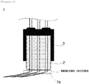
- FIG. 1 is a diagram schematically illustrating a shape of a connector assembly 1 with a female connector 2 having a rectangular-structure female connector 2 in which an inlet of wire harness is flat.
- a female connector 2 and a male connector 3 having a rectangular structure, in which an inlet of wire harness is flat are fitted and coupled to each other.
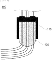
- FIG. 2 is a diagram schematically illustrating a shape of a connector assembly 100 with rounded edges according to an embodiment of the present invention.
- the connector assembly 100 with the rounded edges may be configured to generally include a first connector 110 and a second connector 120 of which one side is coupled to the first connector.
- first connector 110 may mean a male connector having a general shape and the second connector 120 may mean the female connector. Further, the first and second connectors 110 and 120 may be fastened through forcible fitting and coupling to each other.
- the second connector 120 may be formed in a round shape in which the end (more specifically, an end portion in which the wire harness is formed) is not formed to be flat, but laterally symmetric based on a center portion.
- the end of the second connector 120 protrudes outwards and a corner portion is formed in a rounded gentle curve shape, and as a result, one or more wires which extend to the outside of the second connector 120 may be curved according to the round shape of the second connector 120.
- the sudden bending phenomenon and tension increase of the wire may be prevented and the resulting contact failure and disconnection failure, the contact failure of the connector assembly, etc., may be prevented.
- a guide groove 120a may be formed at the end portion of the second connector 120, which prevents the wire which is slowly curved in the curve shape from being pressed between the external structures. This will be described in more detail with reference to FIGS. 3 and 4 .
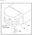
- FIG. 3 is a diagram more specifically illustrating a guide groove 120a illustrated in FIG. 2 .
- the end portion of the second connector 120 is formed to have a round shape in which left and right sides are symmetric to each other, even though the second connector 120 itself moves laterally, the sudden bending phenomenon and the tension increase of the wires which come outside through multiple wire passages formed to penetrate in the longitudinal direction of the second connector 120 may be prevented.
- the guide groove 120a which is dented inside is formed at end portions of partitions partitioning multiple wire passages from each other so as to receive a lateral surface of the wire which comes outside through multiple wire passages.
- the guide groove 120a may be formed at each of all of ends of respective partitions and the size of the guide groove 120a is formed to have an internal space having a size to fully receive the lateral surface of the wire.
- FIG. 4 is a diagram illustrating a state in which a wire is pressed by a male connector 3 and an external structure in the related art and a state in which interference of the wire is removed by the guide groove 120a illustrated in FIG. 3 and the external structure.
- FIG. 4(a) is a diagram illustrating a state in which a wire (corresponding to a cross section in the figure) interposed between an outer surface of the female connector 2 and the outer surface of the external structure is pressed when the female connector 2 in the related art, in which the end corresponds to a flat shape and the external structure (e.g., PCB, etc.) are positioned adjacent to each other.
- a wire corresponding to a cross section in the figure
- the female connector 2 since the female connector 2 has no structure for preventing the wire from being pressed, there is a problem in that the interference cannot but occur while the wire is pressed.
- FIG. 4(b) is a diagram illustrating a state in which the wire is not pressed as the wire (corresponding to the cross section in the figure) is received in the guide groove 120a formed on the partition of the second connector 120 when the second connector 120 and the external structure illustrated in FIG. 3 are positioned adjacent to each other.
Landscapes
- Details Of Connecting Devices For Male And Female Coupling (AREA)
- Connector Housings Or Holding Contact Members (AREA)
- Cable Accessories (AREA)
Abstract
Description
- This application claims priority to and the benefit of Korean Patent Application No.
10-2017-0152279 - The present invention relates to a female connector with rounded edges, and more particularly, to a connector assembly with rounded edges, in which an end of a female connector is formed in a round shape and a guide groove having an inner dimension receiving a wire is formed at an end portion to guide the wire to be curved to correspond to the round shape at a wire harness inlet end and guide the curved wire to be received in the guide groove, thereby guiding reduction of tension of the curved wire and prevention of interference with an external structure.
- In general, in the case of most connector assemblies in which a male connector and a female connector are coupled to each other, an end corner portion of the female connector is formed in a rectangular structure and in this case, a wire harness inlet is flat, and as a result, when bending occurs due to a structural characteristic, a wire is suddenly bent and tilted to a lateral side of a connected terminal, which may cause a contact failure of a connector.
- In the related art, in order to solve such a problem, a predetermined inclined surface is formed at the wire harness inlet to apply a structure to contact the wire with the inclined surface, but in this case, an edge of the inclined surface is not still gentle, but has a pointed structure, and as a result, it is difficult to solve the problem in that the wire is suddenly bent.
- Therefore, in order to solve the problem and a limitation which occur at the wire harness inlet end of the connector in the related art, the present inventor has developed a connector assembly with rounded edges, in which an end of a female connector fastened to a male connector is formed in a round shape and a wire is guided to be curved to correspond to the round shape at a wire harness inlet end to reduce tension applied to the wire, thereby preventing a contact failure and a disconnection failure.
- The present invention relates to a female connector with rounded edges, and more particularly, to a connector assembly with rounded edges, in which an end of a female connector is formed in a round shape and a guide groove having an inner dimension receiving a wire is formed at an end portion to guide the wire to be curved to correspond to the round shape at a wire harness inlet end and guide the curved wire to be received in the guide groove, thereby guiding reduction of tension of the curved wire and prevention of interference with an external structure.
- According to an embodiment of the present invention, a connector assembly with rounded edges includes: first connector; and a second connector of which one side is coupled to the first connector, in which as the other end portion of the second connector is formed in a round shape, one or more wires which extend outwards from one end portion of the second connector are curved in the round shape.
- In an embodiment, the second connector may have a round shape in which both edges are symmetric to each other based on a center portion.
- In an embodiment, the first connector and the second connector may be forcibly fitted and coupled to each other.
- In an embodiment, a guide groove may be formed at end portions of partitions partitioning multiple wire passages formed to penetrate in a longitudinal direction of the second connector, which is dented so as to receive a lateral surface of the wire curved according to the round shape of the second connector.
- In an embodiment, as the guide groove is formed in a shape to correspond to the lateral surface of the wire and is formed to have an internal space to fully receive the lateral surface of the wire, when the wire is curved according to the round shape of the second connector by the external structure, interference between the external structure and a lateral surface of the wire may be removed.
- According to an aspect of the present invention, it is advantageous in that a connector assembly with rounded edges, in which an end of a female connector fastened to a mal connector is formed in a round shape and a wire is guided to be curved to correspond to the round shape at a wire harness inlet end to reduce tension applied to the wire, thereby preventing a contact failure and a disconnection failure.
- In particular, according to an aspect of the present invention, it is advantageous in that as a guide groove is formed at an end portion of a female connector so that the curved wire is curved in a longitudinal direction, even though the wire is curved according to the round shape of the female connector by an external structure, the wire is received in the guide groove, and as a result, interference with the external structure does not occur.
-
-
FIG. 1 is a diagram schematically illustrating a shape of aconnector assembly 1 with afemale connector 2 having a rectangular-structurefemale connector 2 in which an inlet of wire harness is flat. -
FIG. 2 is a diagram schematically illustrating a shape of aconnector assembly 100 with rounded edges according to an embodiment of the present invention. -
FIG. 3 is a diagram more specifically illustrating aguide groove 120a illustrated inFIG. 2 . -
FIG. 4 is a diagram illustrating a state in which a wire is pressed by afemale connector 2 and an external structure in the related art and a state in which interference of the wire is removed by theguide groove 120a illustrated inFIG. 3 and the external structure. - Hereinafter, a preferred embodiment is presented in order to assist understanding of the present invention. However, the following embodiment is just provided to more easily understand the present invention and contents of the present invention are not limited by the embodiment.
-
FIG. 1 is a diagram schematically illustrating a shape of aconnector assembly 1 with afemale connector 2 having a rectangular-structurefemale connector 2 in which an inlet of wire harness is flat. - Referring to
FIG. 1 , in ageneral connector assembly 1, afemale connector 2 and amale connector 3 having a rectangular structure, in which an inlet of wire harness is flat are fitted and coupled to each other. - In this case, since an end of the
female connector 2 is flat, when awire 1a of theconnector assembly 1 is disposed in a structure in which thewire 1a is bent, thewire 1a is suddenly bent by the end of thefemale connector 2. In this case, while tension of a bent portion of thewire 1a suddenly increases, damage to the wire is caused and thewire 1a is suddenly tilted to a lateral side of a terminal, which causes contact failure of theconnector assembly 1. - Accordingly, in the present invention, a technique capable of minimizing a sudden bending phenomenon of the
wire 1a will be described with reference toFIG. 2 . -
FIG. 2 is a diagram schematically illustrating a shape of aconnector assembly 100 with rounded edges according to an embodiment of the present invention. - Referring to
FIG. 2 , theconnector assembly 100 with the rounded edges according to an embodiment of the present invention may be configured to generally include afirst connector 110 and asecond connector 120 of which one side is coupled to the first connector. - Here, the
first connector 110 may mean a male connector having a general shape and thesecond connector 120 may mean the female connector. Further, the first andsecond connectors - In this case, the
second connector 120 may be formed in a round shape in which the end (more specifically, an end portion in which the wire harness is formed) is not formed to be flat, but laterally symmetric based on a center portion. - More specifically, the end of the
second connector 120 protrudes outwards and a corner portion is formed in a rounded gentle curve shape, and as a result, one or more wires which extend to the outside of thesecond connector 120 may be curved according to the round shape of thesecond connector 120. - For example, even in a structure in which the
connector assembly 100 with the rounded edges is disposed to be bent to left and right sides, one or more wires are slowly bent according to a round shape having a gentle curve shape, and as a result, the tension applied to the wire is suddenly reduced. - Accordingly, through the structure of the present invention, even in a structure in which the connector assembly is disposed to be bent, the sudden bending phenomenon and tension increase of the wire may be prevented and the resulting contact failure and disconnection failure, the contact failure of the connector assembly, etc., may be prevented.
- In this case, a
guide groove 120a may be formed at the end portion of thesecond connector 120, which prevents the wire which is slowly curved in the curve shape from being pressed between the external structures. This will be described in more detail with reference toFIGS. 3 and4 . -
FIG. 3 is a diagram more specifically illustrating aguide groove 120a illustrated inFIG. 2 . - Referring to
FIG. 3 , as the end portion of thesecond connector 120 is formed to have a round shape in which left and right sides are symmetric to each other, even though thesecond connector 120 itself moves laterally, the sudden bending phenomenon and the tension increase of the wires which come outside through multiple wire passages formed to penetrate in the longitudinal direction of thesecond connector 120 may be prevented. - In this case, the
guide groove 120a which is dented inside is formed at end portions of partitions partitioning multiple wire passages from each other so as to receive a lateral surface of the wire which comes outside through multiple wire passages. - The
guide groove 120a may be formed at each of all of ends of respective partitions and the size of theguide groove 120a is formed to have an internal space having a size to fully receive the lateral surface of the wire. - Accordingly, even though the wire is curved due to interference with the external structure, the wire is received in the
guide groove 120a, and as a result, interference between the external structure and the lateral surface of the wire is removed, thereby removing damage and cutting of the wire. This will be described in more detail with reference toFIG. 4 . -
FIG. 4 is a diagram illustrating a state in which a wire is pressed by amale connector 3 and an external structure in the related art and a state in which interference of the wire is removed by theguide groove 120a illustrated inFIG. 3 and the external structure. - First, referring to
FIG. 4(a), FIG. 4(a) is a diagram illustrating a state in which a wire (corresponding to a cross section in the figure) interposed between an outer surface of thefemale connector 2 and the outer surface of the external structure is pressed when thefemale connector 2 in the related art, in which the end corresponds to a flat shape and the external structure (e.g., PCB, etc.) are positioned adjacent to each other. - In this case, since the
female connector 2 has no structure for preventing the wire from being pressed, there is a problem in that the interference cannot but occur while the wire is pressed. - On the contrary,
FIG. 4(b) is a diagram illustrating a state in which the wire is not pressed as the wire (corresponding to the cross section in the figure) is received in theguide groove 120a formed on the partition of thesecond connector 120 when thesecond connector 120 and the external structure illustrated inFIG. 3 are positioned adjacent to each other. - In this case, as the wire is fully received in the
guide groove 120a, there is no interference between the wire and the external structure, thereby preventing the damage, cutting, etc., of the wire. - The present invention has been described with reference to the preferred embodiments of the present invention, but those skilled in the art will understand that the present invention can be variously modified and changed without departing from the spirit and the scope of the present invention which are defined in the appended claims.
Claims (5)
- A connector assembly with rounded edges, comprising:a first connector; anda second connector of which one side is coupled to the first connector,wherein as the other end portion of the second connector is formed in a round shape, one or more wires which extend outwards from one end portion of the second connector are curved in the round shape.
- The connector assembly of claim 1, wherein the second connector has a round shape in which both edges are symmetric to each other based on a center portion.
- The connector assembly of claim 1, wherein the first connector and the second connector are forcibly fitted and coupled to each other.
- The connector assembly of claim 1, wherein a guide groove is formed at end portions of partitions partitioning multiple wire passages formed to penetrate in a longitudinal direction of the second connector, which is dented so as to receive a lateral surface of the wire curved according to the round shape of the second connector.
- The connector assembly of claim 4, wherein as the guide groove is formed in a shape to correspond to the lateral surface of the wire and is formed to have an internal space to fully receive the lateral surface of the wire, when the wire is curved according to the round shape of the second connector by the external structure, interference between the external structure and the lateral surface of the wire is removed.
Applications Claiming Priority (2)
| Application Number | Priority Date | Filing Date | Title |
|---|---|---|---|
| KR20170152279 | 2017-11-15 | ||
| PCT/KR2018/011986 WO2019098530A1 (en) | 2017-11-15 | 2018-10-11 | Rounded connector assembly |
Publications (3)
| Publication Number | Publication Date |
|---|---|
| EP3648261A1 true EP3648261A1 (en) | 2020-05-06 |
| EP3648261A4 EP3648261A4 (en) | 2020-08-05 |
| EP3648261B1 EP3648261B1 (en) | 2023-03-01 |
Family
ID=66538760
Family Applications (1)
| Application Number | Title | Priority Date | Filing Date |
|---|---|---|---|
| EP18879917.5A Active EP3648261B1 (en) | 2017-11-15 | 2018-10-11 | Rounded connector assembly |
Country Status (6)
| Country | Link |
|---|---|
| US (1) | US11196209B2 (en) |
| EP (1) | EP3648261B1 (en) |
| JP (1) | JP6896980B2 (en) |
| KR (1) | KR102693646B1 (en) |
| CN (1) | CN110915070B (en) |
| WO (1) | WO2019098530A1 (en) |
Families Citing this family (1)
| Publication number | Priority date | Publication date | Assignee | Title |
|---|---|---|---|---|
| KR102744868B1 (en) | 2019-10-14 | 2024-12-18 | 주식회사 엘지에너지솔루션 | High-tension flat flexible cable assembly |
Family Cites Families (24)
| Publication number | Priority date | Publication date | Assignee | Title |
|---|---|---|---|---|
| JPH01100877A (en) * | 1987-10-12 | 1989-04-19 | Fujitsu Ltd | Cable connector |
| JP3081760B2 (en) * | 1993-11-10 | 2000-08-28 | 矢崎総業株式会社 | Waterproof protective cover |
| US5731546A (en) * | 1996-03-15 | 1998-03-24 | Molex Incorporated | Telecommunications cable management tray with a row of arcuate cable guide walls |
| JP3181890B2 (en) * | 1999-04-15 | 2001-07-03 | ティーディーケイ株式会社 | Cable connector and data input / output card |
| JP4213296B2 (en) | 1999-06-08 | 2009-01-21 | 日本圧着端子製造株式会社 | Low insertion force / High removal force connector |
| JP2001297821A (en) * | 2000-04-13 | 2001-10-26 | Tdk Corp | Cable connector changing jig, cable connector and data input and output card |
| JP4190305B2 (en) * | 2003-02-20 | 2008-12-03 | 富士通コンポーネント株式会社 | Connector with cable |
| JP4053912B2 (en) | 2003-03-19 | 2008-02-27 | ミツミ電機株式会社 | Control adapter device |
| US7249962B2 (en) * | 2003-11-13 | 2007-07-31 | Belden Cdt (Canada) Inc. | Connector assembly |
| ITFI20050185A1 (en) * | 2005-08-31 | 2007-03-01 | Belisario Pini | CASE FOR ELECTRICAL CONNECTIONS AND PROCEDURE FOR MANUFACTURING A SHEET |
| DE102006056001B4 (en) | 2006-11-24 | 2008-12-04 | Phoenix Contact Gmbh & Co. Kg | Field attachable circular connector for Ethernet |
| US7686660B2 (en) | 2008-04-10 | 2010-03-30 | Osram Sylvania Inc. | Connector and receptacle therefor |
| JP5563207B2 (en) | 2008-08-01 | 2014-07-30 | スリーエム イノベイティブ プロパティズ カンパニー | Termination connector |
| US7942690B2 (en) * | 2008-10-24 | 2011-05-17 | Hti Ip, Llc | Cable positioner |
| KR200466411Y1 (en) | 2009-04-14 | 2013-04-18 | 한국단자공업 주식회사 | Connector |
| JP2011239619A (en) | 2010-05-12 | 2011-11-24 | Sumitomo Wiring Syst Ltd | Branch holding jig for wiring harness |
| CN202772338U (en) * | 2012-09-12 | 2013-03-06 | 杭州华三通信技术有限公司 | Electronic equipment |
| JP6011510B2 (en) | 2013-10-24 | 2016-10-19 | 住友電装株式会社 | Connectors and wire harnesses |
| US9331466B2 (en) * | 2014-04-07 | 2016-05-03 | Juiceboxx Inc. | Protective devices for electric power adapters/chargers |
| JP2016046108A (en) * | 2014-08-22 | 2016-04-04 | スタック電子株式会社 | Cable holding member for high frequency coaxial connector and holding mechanism using holding member |
| JP6315339B2 (en) | 2014-10-31 | 2018-04-25 | 住友電装株式会社 | connector |
| JP2016100123A (en) * | 2014-11-19 | 2016-05-30 | 三洋テクノソリューションズ鳥取株式会社 | Cable protector |
| JP2016201235A (en) * | 2015-04-09 | 2016-12-01 | 株式会社オートネットワーク技術研究所 | Electric wire with connector |
| CN205790849U (en) * | 2016-07-01 | 2016-12-07 | 丰钜(北京)科技有限公司 | A kind of cellular phone data line |
-
2018
- 2018-10-10 KR KR1020180120492A patent/KR102693646B1/en active Active
- 2018-10-11 US US16/636,071 patent/US11196209B2/en active Active
- 2018-10-11 CN CN201880047138.3A patent/CN110915070B/en active Active
- 2018-10-11 JP JP2020502293A patent/JP6896980B2/en active Active
- 2018-10-11 EP EP18879917.5A patent/EP3648261B1/en active Active
- 2018-10-11 WO PCT/KR2018/011986 patent/WO2019098530A1/en not_active Ceased
Also Published As
| Publication number | Publication date |
|---|---|
| US20200212618A1 (en) | 2020-07-02 |
| KR102693646B1 (en) | 2024-08-09 |
| EP3648261B1 (en) | 2023-03-01 |
| JP6896980B2 (en) | 2021-06-30 |
| WO2019098530A1 (en) | 2019-05-23 |
| KR20190055724A (en) | 2019-05-23 |
| CN110915070B (en) | 2021-06-22 |
| US11196209B2 (en) | 2021-12-07 |
| CN110915070A (en) | 2020-03-24 |
| JP2020528202A (en) | 2020-09-17 |
| EP3648261A4 (en) | 2020-08-05 |
Similar Documents
| Publication | Publication Date | Title |
|---|---|---|
| US9917389B2 (en) | Flat terminal and socket for electrical plug-and-socket connection | |
| US11631952B2 (en) | Connector assembly and method for manufacturing the same | |
| US20160204539A1 (en) | Connector | |
| US10615521B2 (en) | Coaxial cable connector provided with a housing having a pair of crimping pieces | |
| US7485016B2 (en) | Female terminal with guiding piece | |
| US9768559B2 (en) | Shield housing and socket connector | |
| EP3540855B1 (en) | Connection terminal | |
| US20040108129A1 (en) | Multi-tap compression connector | |
| US10714865B2 (en) | Connector housing with a connecting mechanism to prevent electromagnetic leakage near the insertion port | |
| US11196209B2 (en) | Rounded connector assembly | |
| KR20020016507A (en) | male contact | |
| US9130294B2 (en) | Latchable contact having a primary locking lance overlapped by a side wall | |
| KR101613410B1 (en) | Terminal fitting | |
| US8662922B2 (en) | Power connector | |
| JP2007059096A (en) | Female terminal metal fitting | |
| JP6839005B2 (en) | Terminal bracket | |
| CN208189867U (en) | Connector and its reinforcing frame | |
| KR102711549B1 (en) | Receptacle terminal | |
| US11894634B2 (en) | Connector | |
| JP6407690B2 (en) | Wire relay connector | |
| US20240195113A1 (en) | Plug connector | |
| US20240162631A1 (en) | Connector Terminal, Connector Housing and Connector | |
| CN101859955B (en) | Electric connector and assembly method thereof | |
| KR102872192B1 (en) | Terminal | |
| US10326226B2 (en) | Contact with a first cylindrical section, a second cylindrical section, and a transition section and a connector using the same |
Legal Events
| Date | Code | Title | Description |
|---|---|---|---|
| STAA | Information on the status of an ep patent application or granted ep patent |
Free format text: STATUS: THE INTERNATIONAL PUBLICATION HAS BEEN MADE |
|
| PUAI | Public reference made under article 153(3) epc to a published international application that has entered the european phase |
Free format text: ORIGINAL CODE: 0009012 |
|
| STAA | Information on the status of an ep patent application or granted ep patent |
Free format text: STATUS: REQUEST FOR EXAMINATION WAS MADE |
|
| 17P | Request for examination filed |
Effective date: 20200130 |
|
| AK | Designated contracting states |
Kind code of ref document: A1 Designated state(s): AL AT BE BG CH CY CZ DE DK EE ES FI FR GB GR HR HU IE IS IT LI LT LU LV MC MK MT NL NO PL PT RO RS SE SI SK SM TR |
|
| AX | Request for extension of the european patent |
Extension state: BA ME |
|
| A4 | Supplementary search report drawn up and despatched |
Effective date: 20200708 |
|
| RIC1 | Information provided on ipc code assigned before grant |
Ipc: H01R 13/58 20060101AFI20200702BHEP Ipc: H01R 13/56 20060101ALI20200702BHEP |
|
| DAV | Request for validation of the european patent (deleted) | ||
| DAX | Request for extension of the european patent (deleted) | ||
| STAA | Information on the status of an ep patent application or granted ep patent |
Free format text: STATUS: EXAMINATION IS IN PROGRESS |
|
| 17Q | First examination report despatched |
Effective date: 20211020 |
|
| RAP1 | Party data changed (applicant data changed or rights of an application transferred) |
Owner name: LG ENERGY SOLUTION LTD. |
|
| RAP3 | Party data changed (applicant data changed or rights of an application transferred) |
Owner name: LG ENERGY SOLUTION, LTD. |
|
| GRAP | Despatch of communication of intention to grant a patent |
Free format text: ORIGINAL CODE: EPIDOSNIGR1 |
|
| STAA | Information on the status of an ep patent application or granted ep patent |
Free format text: STATUS: GRANT OF PATENT IS INTENDED |
|
| INTG | Intention to grant announced |
Effective date: 20220930 |
|
| GRAS | Grant fee paid |
Free format text: ORIGINAL CODE: EPIDOSNIGR3 |
|
| GRAA | (expected) grant |
Free format text: ORIGINAL CODE: 0009210 |
|
| STAA | Information on the status of an ep patent application or granted ep patent |
Free format text: STATUS: THE PATENT HAS BEEN GRANTED |
|
| AK | Designated contracting states |
Kind code of ref document: B1 Designated state(s): AL AT BE BG CH CY CZ DE DK EE ES FI FR GB GR HR HU IE IS IT LI LT LU LV MC MK MT NL NO PL PT RO RS SE SI SK SM TR |
|
| REG | Reference to a national code |
Ref country code: GB Ref legal event code: FG4D |
|
| REG | Reference to a national code |
Ref country code: CH Ref legal event code: EP Ref country code: AT Ref legal event code: REF Ref document number: 1551663 Country of ref document: AT Kind code of ref document: T Effective date: 20230315 |
|
| REG | Reference to a national code |
Ref country code: DE Ref legal event code: R096 Ref document number: 602018046807 Country of ref document: DE |
|
| REG | Reference to a national code |
Ref country code: IE Ref legal event code: FG4D |
|
| REG | Reference to a national code |
Ref country code: LT Ref legal event code: MG9D |
|
| P01 | Opt-out of the competence of the unified patent court (upc) registered |
Effective date: 20230525 |
|
| REG | Reference to a national code |
Ref country code: NL Ref legal event code: MP Effective date: 20230301 |
|
| PG25 | Lapsed in a contracting state [announced via postgrant information from national office to epo] |
Ref country code: RS Free format text: LAPSE BECAUSE OF FAILURE TO SUBMIT A TRANSLATION OF THE DESCRIPTION OR TO PAY THE FEE WITHIN THE PRESCRIBED TIME-LIMIT Effective date: 20230301 Ref country code: NO Free format text: LAPSE BECAUSE OF FAILURE TO SUBMIT A TRANSLATION OF THE DESCRIPTION OR TO PAY THE FEE WITHIN THE PRESCRIBED TIME-LIMIT Effective date: 20230601 Ref country code: LV Free format text: LAPSE BECAUSE OF FAILURE TO SUBMIT A TRANSLATION OF THE DESCRIPTION OR TO PAY THE FEE WITHIN THE PRESCRIBED TIME-LIMIT Effective date: 20230301 Ref country code: LT Free format text: LAPSE BECAUSE OF FAILURE TO SUBMIT A TRANSLATION OF THE DESCRIPTION OR TO PAY THE FEE WITHIN THE PRESCRIBED TIME-LIMIT Effective date: 20230301 Ref country code: HR Free format text: LAPSE BECAUSE OF FAILURE TO SUBMIT A TRANSLATION OF THE DESCRIPTION OR TO PAY THE FEE WITHIN THE PRESCRIBED TIME-LIMIT Effective date: 20230301 Ref country code: ES Free format text: LAPSE BECAUSE OF FAILURE TO SUBMIT A TRANSLATION OF THE DESCRIPTION OR TO PAY THE FEE WITHIN THE PRESCRIBED TIME-LIMIT Effective date: 20230301 |
|
| REG | Reference to a national code |
Ref country code: AT Ref legal event code: MK05 Ref document number: 1551663 Country of ref document: AT Kind code of ref document: T Effective date: 20230301 |
|
| PG25 | Lapsed in a contracting state [announced via postgrant information from national office to epo] |
Ref country code: SE Free format text: LAPSE BECAUSE OF FAILURE TO SUBMIT A TRANSLATION OF THE DESCRIPTION OR TO PAY THE FEE WITHIN THE PRESCRIBED TIME-LIMIT Effective date: 20230301 Ref country code: PL Free format text: LAPSE BECAUSE OF FAILURE TO SUBMIT A TRANSLATION OF THE DESCRIPTION OR TO PAY THE FEE WITHIN THE PRESCRIBED TIME-LIMIT Effective date: 20230301 Ref country code: NL Free format text: LAPSE BECAUSE OF FAILURE TO SUBMIT A TRANSLATION OF THE DESCRIPTION OR TO PAY THE FEE WITHIN THE PRESCRIBED TIME-LIMIT Effective date: 20230301 Ref country code: GR Free format text: LAPSE BECAUSE OF FAILURE TO SUBMIT A TRANSLATION OF THE DESCRIPTION OR TO PAY THE FEE WITHIN THE PRESCRIBED TIME-LIMIT Effective date: 20230602 Ref country code: FI Free format text: LAPSE BECAUSE OF FAILURE TO SUBMIT A TRANSLATION OF THE DESCRIPTION OR TO PAY THE FEE WITHIN THE PRESCRIBED TIME-LIMIT Effective date: 20230301 |
|
| PG25 | Lapsed in a contracting state [announced via postgrant information from national office to epo] |
Ref country code: SM Free format text: LAPSE BECAUSE OF FAILURE TO SUBMIT A TRANSLATION OF THE DESCRIPTION OR TO PAY THE FEE WITHIN THE PRESCRIBED TIME-LIMIT Effective date: 20230301 Ref country code: RO Free format text: LAPSE BECAUSE OF FAILURE TO SUBMIT A TRANSLATION OF THE DESCRIPTION OR TO PAY THE FEE WITHIN THE PRESCRIBED TIME-LIMIT Effective date: 20230301 Ref country code: PT Free format text: LAPSE BECAUSE OF FAILURE TO SUBMIT A TRANSLATION OF THE DESCRIPTION OR TO PAY THE FEE WITHIN THE PRESCRIBED TIME-LIMIT Effective date: 20230703 Ref country code: EE Free format text: LAPSE BECAUSE OF FAILURE TO SUBMIT A TRANSLATION OF THE DESCRIPTION OR TO PAY THE FEE WITHIN THE PRESCRIBED TIME-LIMIT Effective date: 20230301 Ref country code: CZ Free format text: LAPSE BECAUSE OF FAILURE TO SUBMIT A TRANSLATION OF THE DESCRIPTION OR TO PAY THE FEE WITHIN THE PRESCRIBED TIME-LIMIT Effective date: 20230301 Ref country code: AT Free format text: LAPSE BECAUSE OF FAILURE TO SUBMIT A TRANSLATION OF THE DESCRIPTION OR TO PAY THE FEE WITHIN THE PRESCRIBED TIME-LIMIT Effective date: 20230301 |
|
| PG25 | Lapsed in a contracting state [announced via postgrant information from national office to epo] |
Ref country code: SK Free format text: LAPSE BECAUSE OF FAILURE TO SUBMIT A TRANSLATION OF THE DESCRIPTION OR TO PAY THE FEE WITHIN THE PRESCRIBED TIME-LIMIT Effective date: 20230301 Ref country code: IS Free format text: LAPSE BECAUSE OF FAILURE TO SUBMIT A TRANSLATION OF THE DESCRIPTION OR TO PAY THE FEE WITHIN THE PRESCRIBED TIME-LIMIT Effective date: 20230701 |
|
| REG | Reference to a national code |
Ref country code: DE Ref legal event code: R097 Ref document number: 602018046807 Country of ref document: DE |
|
| PLBE | No opposition filed within time limit |
Free format text: ORIGINAL CODE: 0009261 |
|
| STAA | Information on the status of an ep patent application or granted ep patent |
Free format text: STATUS: NO OPPOSITION FILED WITHIN TIME LIMIT |
|
| PG25 | Lapsed in a contracting state [announced via postgrant information from national office to epo] |
Ref country code: SI Free format text: LAPSE BECAUSE OF FAILURE TO SUBMIT A TRANSLATION OF THE DESCRIPTION OR TO PAY THE FEE WITHIN THE PRESCRIBED TIME-LIMIT Effective date: 20230301 Ref country code: DK Free format text: LAPSE BECAUSE OF FAILURE TO SUBMIT A TRANSLATION OF THE DESCRIPTION OR TO PAY THE FEE WITHIN THE PRESCRIBED TIME-LIMIT Effective date: 20230301 |
|
| 26N | No opposition filed |
Effective date: 20231204 |
|
| PG25 | Lapsed in a contracting state [announced via postgrant information from national office to epo] |
Ref country code: IT Free format text: LAPSE BECAUSE OF FAILURE TO SUBMIT A TRANSLATION OF THE DESCRIPTION OR TO PAY THE FEE WITHIN THE PRESCRIBED TIME-LIMIT Effective date: 20230301 Ref country code: MC Free format text: LAPSE BECAUSE OF FAILURE TO SUBMIT A TRANSLATION OF THE DESCRIPTION OR TO PAY THE FEE WITHIN THE PRESCRIBED TIME-LIMIT Effective date: 20230301 |
|
| REG | Reference to a national code |
Ref country code: CH Ref legal event code: PL |
|
| REG | Reference to a national code |
Ref country code: BE Ref legal event code: MM Effective date: 20231031 |
|
| PG25 | Lapsed in a contracting state [announced via postgrant information from national office to epo] |
Ref country code: LU Free format text: LAPSE BECAUSE OF NON-PAYMENT OF DUE FEES Effective date: 20231011 |
|
| PG25 | Lapsed in a contracting state [announced via postgrant information from national office to epo] |
Ref country code: LU Free format text: LAPSE BECAUSE OF NON-PAYMENT OF DUE FEES Effective date: 20231011 |
|
| PG25 | Lapsed in a contracting state [announced via postgrant information from national office to epo] |
Ref country code: CH Free format text: LAPSE BECAUSE OF NON-PAYMENT OF DUE FEES Effective date: 20231031 |
|
| PG25 | Lapsed in a contracting state [announced via postgrant information from national office to epo] |
Ref country code: CH Free format text: LAPSE BECAUSE OF NON-PAYMENT OF DUE FEES Effective date: 20231031 |
|
| PG25 | Lapsed in a contracting state [announced via postgrant information from national office to epo] |
Ref country code: BE Free format text: LAPSE BECAUSE OF NON-PAYMENT OF DUE FEES Effective date: 20231031 |
|
| PG25 | Lapsed in a contracting state [announced via postgrant information from national office to epo] |
Ref country code: IE Free format text: LAPSE BECAUSE OF NON-PAYMENT OF DUE FEES Effective date: 20231011 |
|
| PG25 | Lapsed in a contracting state [announced via postgrant information from national office to epo] |
Ref country code: IE Free format text: LAPSE BECAUSE OF NON-PAYMENT OF DUE FEES Effective date: 20231011 |
|
| PG25 | Lapsed in a contracting state [announced via postgrant information from national office to epo] |
Ref country code: BG Free format text: LAPSE BECAUSE OF FAILURE TO SUBMIT A TRANSLATION OF THE DESCRIPTION OR TO PAY THE FEE WITHIN THE PRESCRIBED TIME-LIMIT Effective date: 20230301 |
|
| PG25 | Lapsed in a contracting state [announced via postgrant information from national office to epo] |
Ref country code: BG Free format text: LAPSE BECAUSE OF FAILURE TO SUBMIT A TRANSLATION OF THE DESCRIPTION OR TO PAY THE FEE WITHIN THE PRESCRIBED TIME-LIMIT Effective date: 20230301 |
|
| PG25 | Lapsed in a contracting state [announced via postgrant information from national office to epo] |
Ref country code: CY Free format text: LAPSE BECAUSE OF FAILURE TO SUBMIT A TRANSLATION OF THE DESCRIPTION OR TO PAY THE FEE WITHIN THE PRESCRIBED TIME-LIMIT; INVALID AB INITIO Effective date: 20181011 |
|
| PG25 | Lapsed in a contracting state [announced via postgrant information from national office to epo] |
Ref country code: HU Free format text: LAPSE BECAUSE OF FAILURE TO SUBMIT A TRANSLATION OF THE DESCRIPTION OR TO PAY THE FEE WITHIN THE PRESCRIBED TIME-LIMIT; INVALID AB INITIO Effective date: 20181011 |
|
| PGFP | Annual fee paid to national office [announced via postgrant information from national office to epo] |
Ref country code: GB Payment date: 20250922 Year of fee payment: 8 |
|
| PGFP | Annual fee paid to national office [announced via postgrant information from national office to epo] |
Ref country code: FR Payment date: 20250925 Year of fee payment: 8 |
|
| PG25 | Lapsed in a contracting state [announced via postgrant information from national office to epo] |
Ref country code: TR Free format text: LAPSE BECAUSE OF FAILURE TO SUBMIT A TRANSLATION OF THE DESCRIPTION OR TO PAY THE FEE WITHIN THE PRESCRIBED TIME-LIMIT Effective date: 20230301 |
|
| PGFP | Annual fee paid to national office [announced via postgrant information from national office to epo] |
Ref country code: DE Payment date: 20250922 Year of fee payment: 8 |