EP3648235A1 - Battery pack having fastening recognition function - Google Patents
Battery pack having fastening recognition function Download PDFInfo
- Publication number
- EP3648235A1 EP3648235A1 EP18872702.8A EP18872702A EP3648235A1 EP 3648235 A1 EP3648235 A1 EP 3648235A1 EP 18872702 A EP18872702 A EP 18872702A EP 3648235 A1 EP3648235 A1 EP 3648235A1
- Authority
- EP
- European Patent Office
- Prior art keywords
- battery pack
- external apparatus
- mcu
- afe
- coupled
- Prior art date
- Legal status (The legal status is an assumption and is not a legal conclusion. Google has not performed a legal analysis and makes no representation as to the accuracy of the status listed.)
- Granted
Links
Images

Classifications
-
- H—ELECTRICITY
- H02—GENERATION; CONVERSION OR DISTRIBUTION OF ELECTRIC POWER
- H02J—ELECTRIC POWER NETWORKS; CIRCUIT ARRANGEMENTS OR SYSTEMS FOR SUPPLYING OR DISTRIBUTING ELECTRIC POWER; SYSTEMS FOR STORING ELECTRIC ENERGY
- H02J7/00—Circuit arrangements for charging or discharging batteries or for supplying loads from batteries
- H02J7/60—Circuit arrangements for charging or discharging batteries or for supplying loads from batteries including safety or protection arrangements
- H02J7/663—Circuit arrangements for charging or discharging batteries or for supplying loads from batteries including safety or protection arrangements using battery or load disconnect circuits
-
- H—ELECTRICITY
- H01—ELECTRIC ELEMENTS
- H01M—PROCESSES OR MEANS, e.g. BATTERIES, FOR THE DIRECT CONVERSION OF CHEMICAL ENERGY INTO ELECTRICAL ENERGY
- H01M10/00—Secondary cells; Manufacture thereof
- H01M10/42—Methods or arrangements for servicing or maintenance of secondary cells or secondary half-cells
- H01M10/425—Structural combination with electronic components, e.g. electronic circuits integrated to the outside of the casing
-
- H—ELECTRICITY
- H01—ELECTRIC ELEMENTS
- H01M—PROCESSES OR MEANS, e.g. BATTERIES, FOR THE DIRECT CONVERSION OF CHEMICAL ENERGY INTO ELECTRICAL ENERGY
- H01M10/00—Secondary cells; Manufacture thereof
- H01M10/42—Methods or arrangements for servicing or maintenance of secondary cells or secondary half-cells
- H01M10/4221—Methods or arrangements for servicing or maintenance of secondary cells or secondary half-cells with battery type recognition
-
- H—ELECTRICITY
- H01—ELECTRIC ELEMENTS
- H01M—PROCESSES OR MEANS, e.g. BATTERIES, FOR THE DIRECT CONVERSION OF CHEMICAL ENERGY INTO ELECTRICAL ENERGY
- H01M10/00—Secondary cells; Manufacture thereof
- H01M10/42—Methods or arrangements for servicing or maintenance of secondary cells or secondary half-cells
- H01M10/48—Accumulators combined with arrangements for measuring, testing or indicating the condition of cells, e.g. the level or density of the electrolyte
-
- H—ELECTRICITY
- H01—ELECTRIC ELEMENTS
- H01M—PROCESSES OR MEANS, e.g. BATTERIES, FOR THE DIRECT CONVERSION OF CHEMICAL ENERGY INTO ELECTRICAL ENERGY
- H01M10/00—Secondary cells; Manufacture thereof
- H01M10/42—Methods or arrangements for servicing or maintenance of secondary cells or secondary half-cells
- H01M10/48—Accumulators combined with arrangements for measuring, testing or indicating the condition of cells, e.g. the level or density of the electrolyte
- H01M10/486—Accumulators combined with arrangements for measuring, testing or indicating the condition of cells, e.g. the level or density of the electrolyte for measuring temperature
-
- H—ELECTRICITY
- H01—ELECTRIC ELEMENTS
- H01M—PROCESSES OR MEANS, e.g. BATTERIES, FOR THE DIRECT CONVERSION OF CHEMICAL ENERGY INTO ELECTRICAL ENERGY
- H01M50/00—Constructional details or processes of manufacture of the non-active parts of electrochemical cells other than fuel cells, e.g. hybrid cells
- H01M50/20—Mountings; Secondary casings or frames; Racks, modules or packs; Suspension devices; Shock absorbers; Transport or carrying devices; Holders
- H01M50/296—Mountings; Secondary casings or frames; Racks, modules or packs; Suspension devices; Shock absorbers; Transport or carrying devices; Holders characterised by terminals of battery packs
-
- H—ELECTRICITY
- H02—GENERATION; CONVERSION OR DISTRIBUTION OF ELECTRIC POWER
- H02J—ELECTRIC POWER NETWORKS; CIRCUIT ARRANGEMENTS OR SYSTEMS FOR SUPPLYING OR DISTRIBUTING ELECTRIC POWER; SYSTEMS FOR STORING ELECTRIC ENERGY
- H02J7/00—Circuit arrangements for charging or discharging batteries or for supplying loads from batteries
-
- H—ELECTRICITY
- H02—GENERATION; CONVERSION OR DISTRIBUTION OF ELECTRIC POWER
- H02J—ELECTRIC POWER NETWORKS; CIRCUIT ARRANGEMENTS OR SYSTEMS FOR SUPPLYING OR DISTRIBUTING ELECTRIC POWER; SYSTEMS FOR STORING ELECTRIC ENERGY
- H02J7/00—Circuit arrangements for charging or discharging batteries or for supplying loads from batteries
- H02J7/40—Circuit arrangements for charging or discharging batteries or for supplying loads from batteries characterised by the exchange of charge or discharge related data
- H02J7/44—Circuit arrangements for charging or discharging batteries or for supplying loads from batteries characterised by the exchange of charge or discharge related data between battery management systems and power sources
-
- H—ELECTRICITY
- H02—GENERATION; CONVERSION OR DISTRIBUTION OF ELECTRIC POWER
- H02J—ELECTRIC POWER NETWORKS; CIRCUIT ARRANGEMENTS OR SYSTEMS FOR SUPPLYING OR DISTRIBUTING ELECTRIC POWER; SYSTEMS FOR STORING ELECTRIC ENERGY
- H02J7/00—Circuit arrangements for charging or discharging batteries or for supplying loads from batteries
- H02J7/50—Circuit arrangements for charging or discharging batteries or for supplying loads from batteries acting upon multiple batteries simultaneously or sequentially
- H02J7/52—Circuit arrangements for charging or discharging batteries or for supplying loads from batteries acting upon multiple batteries simultaneously or sequentially for charge balancing, e.g. equalisation of charge between batteries
-
- H—ELECTRICITY
- H02—GENERATION; CONVERSION OR DISTRIBUTION OF ELECTRIC POWER
- H02J—ELECTRIC POWER NETWORKS; CIRCUIT ARRANGEMENTS OR SYSTEMS FOR SUPPLYING OR DISTRIBUTING ELECTRIC POWER; SYSTEMS FOR STORING ELECTRIC ENERGY
- H02J7/00—Circuit arrangements for charging or discharging batteries or for supplying loads from batteries
- H02J7/60—Circuit arrangements for charging or discharging batteries or for supplying loads from batteries including safety or protection arrangements
- H02J7/61—Circuit arrangements for charging or discharging batteries or for supplying loads from batteries including safety or protection arrangements against overcharge
-
- H—ELECTRICITY
- H02—GENERATION; CONVERSION OR DISTRIBUTION OF ELECTRIC POWER
- H02J—ELECTRIC POWER NETWORKS; CIRCUIT ARRANGEMENTS OR SYSTEMS FOR SUPPLYING OR DISTRIBUTING ELECTRIC POWER; SYSTEMS FOR STORING ELECTRIC ENERGY
- H02J7/00—Circuit arrangements for charging or discharging batteries or for supplying loads from batteries
- H02J7/60—Circuit arrangements for charging or discharging batteries or for supplying loads from batteries including safety or protection arrangements
- H02J7/63—Circuit arrangements for charging or discharging batteries or for supplying loads from batteries including safety or protection arrangements against overdischarge
-
- H—ELECTRICITY
- H02—GENERATION; CONVERSION OR DISTRIBUTION OF ELECTRIC POWER
- H02J—ELECTRIC POWER NETWORKS; CIRCUIT ARRANGEMENTS OR SYSTEMS FOR SUPPLYING OR DISTRIBUTING ELECTRIC POWER; SYSTEMS FOR STORING ELECTRIC ENERGY
- H02J7/00—Circuit arrangements for charging or discharging batteries or for supplying loads from batteries
- H02J7/60—Circuit arrangements for charging or discharging batteries or for supplying loads from batteries including safety or protection arrangements
- H02J7/685—Circuit arrangements for charging or discharging batteries or for supplying loads from batteries including safety or protection arrangements using connection detecting circuits
-
- H—ELECTRICITY
- H02—GENERATION; CONVERSION OR DISTRIBUTION OF ELECTRIC POWER
- H02J—ELECTRIC POWER NETWORKS; CIRCUIT ARRANGEMENTS OR SYSTEMS FOR SUPPLYING OR DISTRIBUTING ELECTRIC POWER; SYSTEMS FOR STORING ELECTRIC ENERGY
- H02J7/00—Circuit arrangements for charging or discharging batteries or for supplying loads from batteries
- H02J7/70—Circuit arrangements for charging or discharging batteries or for supplying loads from batteries characterised by the mechanical construction
- H02J7/751—Circuit arrangements for charging or discharging batteries or for supplying loads from batteries characterised by the mechanical construction concerning the insertion or the connection of the batteries
-
- H—ELECTRICITY
- H02—GENERATION; CONVERSION OR DISTRIBUTION OF ELECTRIC POWER
- H02J—ELECTRIC POWER NETWORKS; CIRCUIT ARRANGEMENTS OR SYSTEMS FOR SUPPLYING OR DISTRIBUTING ELECTRIC POWER; SYSTEMS FOR STORING ELECTRIC ENERGY
- H02J7/00—Circuit arrangements for charging or discharging batteries or for supplying loads from batteries
- H02J7/80—Circuit arrangements for charging or discharging batteries or for supplying loads from batteries including monitoring or indicating arrangements
-
- H—ELECTRICITY
- H01—ELECTRIC ELEMENTS
- H01M—PROCESSES OR MEANS, e.g. BATTERIES, FOR THE DIRECT CONVERSION OF CHEMICAL ENERGY INTO ELECTRICAL ENERGY
- H01M10/00—Secondary cells; Manufacture thereof
- H01M10/42—Methods or arrangements for servicing or maintenance of secondary cells or secondary half-cells
- H01M10/425—Structural combination with electronic components, e.g. electronic circuits integrated to the outside of the casing
- H01M2010/4271—Battery management systems including electronic circuits, e.g. control of current or voltage to keep battery in healthy state, cell balancing
-
- H—ELECTRICITY
- H01—ELECTRIC ELEMENTS
- H01M—PROCESSES OR MEANS, e.g. BATTERIES, FOR THE DIRECT CONVERSION OF CHEMICAL ENERGY INTO ELECTRICAL ENERGY
- H01M10/00—Secondary cells; Manufacture thereof
- H01M10/42—Methods or arrangements for servicing or maintenance of secondary cells or secondary half-cells
- H01M10/425—Structural combination with electronic components, e.g. electronic circuits integrated to the outside of the casing
- H01M2010/4278—Systems for data transfer from batteries, e.g. transfer of battery parameters to a controller, data transferred between battery controller and main controller
-
- H—ELECTRICITY
- H01—ELECTRIC ELEMENTS
- H01M—PROCESSES OR MEANS, e.g. BATTERIES, FOR THE DIRECT CONVERSION OF CHEMICAL ENERGY INTO ELECTRICAL ENERGY
- H01M2220/00—Batteries for particular applications
- H01M2220/10—Batteries in stationary systems, e.g. emergency power source in plant
-
- H—ELECTRICITY
- H01—ELECTRIC ELEMENTS
- H01M—PROCESSES OR MEANS, e.g. BATTERIES, FOR THE DIRECT CONVERSION OF CHEMICAL ENERGY INTO ELECTRICAL ENERGY
- H01M2220/00—Batteries for particular applications
- H01M2220/20—Batteries in motive systems, e.g. vehicle, ship, plane
-
- H—ELECTRICITY
- H01—ELECTRIC ELEMENTS
- H01M—PROCESSES OR MEANS, e.g. BATTERIES, FOR THE DIRECT CONVERSION OF CHEMICAL ENERGY INTO ELECTRICAL ENERGY
- H01M2220/00—Batteries for particular applications
- H01M2220/30—Batteries in portable systems, e.g. mobile phone, laptop
-
- Y—GENERAL TAGGING OF NEW TECHNOLOGICAL DEVELOPMENTS; GENERAL TAGGING OF CROSS-SECTIONAL TECHNOLOGIES SPANNING OVER SEVERAL SECTIONS OF THE IPC; TECHNICAL SUBJECTS COVERED BY FORMER USPC CROSS-REFERENCE ART COLLECTIONS [XRACs] AND DIGESTS
- Y02—TECHNOLOGIES OR APPLICATIONS FOR MITIGATION OR ADAPTATION AGAINST CLIMATE CHANGE
- Y02E—REDUCTION OF GREENHOUSE GAS [GHG] EMISSIONS, RELATED TO ENERGY GENERATION, TRANSMISSION OR DISTRIBUTION
- Y02E60/00—Enabling technologies; Technologies with a potential or indirect contribution to GHG emissions mitigation
- Y02E60/10—Energy storage using batteries
-
- Y—GENERAL TAGGING OF NEW TECHNOLOGICAL DEVELOPMENTS; GENERAL TAGGING OF CROSS-SECTIONAL TECHNOLOGIES SPANNING OVER SEVERAL SECTIONS OF THE IPC; TECHNICAL SUBJECTS COVERED BY FORMER USPC CROSS-REFERENCE ART COLLECTIONS [XRACs] AND DIGESTS
- Y02—TECHNOLOGIES OR APPLICATIONS FOR MITIGATION OR ADAPTATION AGAINST CLIMATE CHANGE
- Y02T—CLIMATE CHANGE MITIGATION TECHNOLOGIES RELATED TO TRANSPORTATION
- Y02T90/00—Enabling technologies or technologies with a potential or indirect contribution to GHG emissions mitigation
- Y02T90/40—Application of hydrogen technology to transportation, e.g. using fuel cells
Definitions
- the present disclosure relates to a battery pack equipped with a function of booting the battery pack when the battery pack is coupled to an external apparatus.
- a large-capacity secondary battery is provided by connecting a plurality of high-output secondary batteries in series so as to be usable for an apparatus, such as an electric vehicle, requiring strong power for driving a motor.
- a single large-capacity secondary battery (hereinafter referred to as "battery”) is composed of a plurality of batteries generally connected in series.
- a control unit that monitors and controls a state of the battery on the whole.
- the control unit monitors the voltage, current, temperature, etc., of a battery, estimates the state of charge (SOC) of the battery by calculation, and controls the battery.
- control unit operates in a discharging or charging state, but when the battery is not a discharging or charging state, since the control unit consumes power, it is necessary to turn off the control unit to reduce power consumption.
- control unit when the battery was not in a discharging or charging state, in related arts, in order to reduce power consumption of the control part, the control unit was allowed to operate in a sleep mode and the battery was continuously checked whether to be coupled to an external apparatus.
- the present disclosure proposes a battery pack which allows the battery to enter into a shutdown mode or a power-down mode when the battery is not coupled to an external apparatus, and release the shutdown mode or the power-down mode when the battery is coupled to an external apparatus.
- the present disclosure provides a battery pack which operates only when coupled to an external apparatus.
- a battery pack which is booted when coupled to an external apparatus, includes: a connector which is a member configured to connect the external apparatus and the battery pack; and a booting circuit configured to start operation of the battery pack when the battery pack and the external apparatus are coupled, wherein the connector includes: a (+) output terminal connected to a (+) output terminal of the battery pack; a coupling check terminal configured to check whether the external apparatus and the battery pack are coupled; a data transceiving terminal configured to tranceive data between the external apparatus and the battery pack; and a (-) output terminal connected to a (-) output terminal of the battery pack.
- the battery pack may further include: a plurality of battery cells; an MCU configured to control the plurality of cells; an AFE configured to control an interface between the MCU and the plurality of batter cells, wherein the booting circuit may be provided between the AFE and the coupling check terminal, and when the battery pack and the external apparatus are coupled, an output of the (+) output terminal of the battery pack may be input to the coupling check terminal via the external apparatus and boot the AFE which has been shut down.
- the booting circuit may include a voltage distribution circuit configured to distribute a voltage of the battery pack
- the booting circuit may boot the AFE which has been shut down, and then transmit, to the MCU, coupling state check information which informs the MCU about whether the battery pack and the external apparatus are coupled.
- the AFE may include: a second protecting module; a short detection module; a current, voltage, and temperature measuring module configured to measure current, voltage, and temperature of the cells; a cell balancing module configured to uniformly adjust charging amounts of the plurality of cells; and an I 2 C communication module configured to communicate with the MCU, wherein the AFE, when receiving a shutdown command from the MCU, may be shutdown
- the MCU may include: a current, voltage, and temperature control module configured to control the current, voltage, and temperature of each of the plurality of cells; a protecting module configured to protect a battery from overcharge and over-discharge on the basis of the current, voltage, and temperature; an FET control module configured to control an FET of the battery pack; and a balancing control module configured to control balancing of the plurality of cells, wherein when the coupling state check information received from the booting circuit is a coupled state, the MCU may receive power via the AFE and operates, and when the coupling state check information received from the booting circuit is an un
- the external apparatus coupled to the battery pack in accordance with an exemplary embodiment may be configured to include a battery coupling part which couples the battery pack and the external apparatus, and the battery coupling part may be configured to include a conductive member which forms a current path between the (+) output terminals of the connector and the coupling check terminal of the connector.
- the conductive member may have a predetermined resistance value
- the battery pack according to the predetermined resistance value, may recognize the types of the external apparatus coupled to the battery pack.
- a battery pack operates only when coupled to an external apparatus, and therefore has very little power consumption. Thus, even when the battery is stored for a long time period, a low-voltage problem caused by the discharge of the battery pack may not occur.
- first and second are used herein to describe various elements, these elements should not be limited by these terms. These terms are only used to distinguish one element from other elements. For example, a first element could be termed a second element, and similarly, a second element could be termed a first element, without departing from the scope of the present invention.
- the terms are used only for explaining a specific exemplary embodiment while not limiting the present invention.
- the singular forms are intended to include the plural forms as well, unless the context clearly indicates otherwise.
- FIG. 1 is a view schematically illustrating configuration of a battery pack in accordance with an exemplary embodiment.
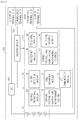
- FIG. 2 is a view illustrating in detail detailed configuration of a battery pack in accordance with an exemplary embodiment.
- a battery pack 100 in accordance with an exemplary embodiment when coupled to an external apparatus 200, may automatically be booted, and when the coupling to the external apparatus is released, may enter into a shutdown mode.
- the battery pack 100 of an exemplary embodiment may be configured to include: a connector 110 which is a member for connecting the external apparatus 200 and the battery pack 100; and a booting circuit 120 which allows the battery to start operation when the battery pack 100 and the external apparatus 200 are coupled.
- the connector 110 may be configured to include: a (+) output terminal 111 connected to a (+) output terminal of the battery pack 100; a coupling check terminal 112 for checking whether the external apparatus 200 and the battery pack 100 are coupled; a data transceiving terminal 113 for transceiving data between the external apparatus 200 and the battery pack 100; and a (-) output terminal 114 connected to a(-) output terminal of the battery pack 100.
- the battery pack 100 may be configured to further include: a plurality of battery cells 130; an MCU 140 which controls the plurality of cells 130; and an AFE 150 which controls an interface between the plurality of battery cells 130.
- the booting circuit 120 is provided between the AFE 150 and the coupling check terminal 112.
- an output of the (+) output terminal of the battery pack 100 may be input to the coupling check terminal 112 via the external apparatus, and boot the AFE 150 which has been shut down.
- the booting circuit 120 may be configured to include a system input node 121connected to the external apparatus 200 and a voltage distribution circuit which distributes the voltage of the battery pack.
- the voltage distribution circuit may be configured to include a plurality of resistors and a plurality of FETs, and the plurality of FETs may operate according to a voltage applied between the (+) output terminal of the battery pack and a ground.
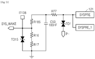
- the voltage distribution circuit may be configured as illustrated in FIG. 3 .
- a booting voltage applied to the AFE by the resistors constituting the voltage distribution circuit may be smaller than the output voltage of the battery pack.
- the booting circuit 120 after booting the AFE 150 which has been shut down, may transmit, to the MCU 140, coupling state check information, which is the state information of a system input node of the booting circuit 150, and inform the MCU about whether the battery pack 100 and the external apparatus 200 are coupled.
- the booting circuit 120 after booting the AFE 150 which has been temporarily shut down, does not generate a booting signal any more, and may transmit to the MCU 140 only the coupling state check information.
- the coupling state check information transmitted to the MCU 140 may be transmitted continuously or at predetermined periods, or transmitted only when the MCU requests the information.
- the AFE 150 may be configured to include: a second protecting module 151; a short detection module 152; a current, voltage, and temperature measuring module 153 which measures the current, voltage, and temperature of cells; a cell balancing module 154 which adjusts charging amounts of the plurality of cells; and an I 2 C communication module 155 which communicates with the MCU 140.
- the AFE 150 may be shut down when receiving a shutdown command from the MCU 140.
- the MCU 140 may be configured to include: a current, voltage, and temperature control module 141 which controls current, voltage, and temperature; a protecting module 142 which protects the batteries from over-charge and over-discharge of the batteries on the basis of the current, voltage, and temperature; a FET control module 143 which controls the FET of the battery pack; and a balancing control module 144 which controls the balancing of the plurality of cells.
- the MCU 140 when the coupling state check information received from the booting circuit 120 is a coupling state, may operate by receiving power through the AFE 150, and when the coupling state check information received from the booting circuit 120 is a coupling released state, a shutdown entering signal may be generated to shutdown the MCU 140 itself, and may transmit the shutdown signal to the AFE 150.
- the booting circuit 120 boots the AFE 150 using an output voltage of the (+) output terminal of the battery pack, and the booted AFE 150 may apply an operation voltage to boot the AFE 150, and the booted AFE 150 may apply an operation voltage to the MCU 140 to operate the MCU 140.
- the booting circuit 120 transmits an uncoupling signal to the MCU 140, the MCU 140 which receives the signal performs a predetermined step for entering into the shutdown mode, and then the MCU 140 itself is shutdown.
- the MCU 140 may transmit a shutdown signal to shut down the AFE 150.
- the battery pack 100 when using the battery pack 100 in accordance with the exemplary embodiment, when the battery pack 100 is not in a state of being coupled to an external apparatus 200, the battery pack enters into the shutdown mode, whereby power consumption may be reduced compared to related arts in which the battery pack operates in a sleep mode and checks coupling. Therefore, even when the battery pack is stored for a long time, the problem of occurrence of low vow voltage caused by battery discharge may be reduced.
- the battery pack 100 when the battery pack 100 is shut down, the battery pack should directly be booted to boot the battery pack, but in the battery pack in accordance with an exemplary embodiment even when having been shutdown, when an external apparatus is coupled, the battery pack itself may recognize the coupling to an external apparatus and be booted.
- the battery pack in accordance with the exemplary embodiment may further be provided with a fuse 160 between the plurality of cells constituting the battery pack 100 and the (+) output terminals of the battery pack.
- the fuse 160 further provided as such may cutoff an over-current flowing in the battery pack even when the second protecting module of the AFE 150 and the protecting module of the MCU 140 may not normally cutoff the over-current, whereby the stability of the battery may be secured.
- the external apparatus 200 coupled to the battery pack in accordance with the exemplary embodiment may be configured to include a battery coupling part which couples the battery pack and the external apparatus, and the battery coupling part may be configured to include a conductive member which forms a current path between the (+) output terminals of the connector and the coupling check terminal.
- the conductive member has a predetermined resistance value
- the battery pack may recognize the types of the external apparatus coupled to the battery pack.
- the predetermined resistance is approximately 10 M ⁇ or greater, it may be determined that an electronic device using the battery pack as a power source is coupled as an external apparatus, and when the predetermined resistance is less than approximately 1 M ⁇ , it may be determined that a charger is coupled as an external apparatus.
Landscapes
- Engineering & Computer Science (AREA)
- Chemical & Material Sciences (AREA)
- Chemical Kinetics & Catalysis (AREA)
- Electrochemistry (AREA)
- General Chemical & Material Sciences (AREA)
- Power Engineering (AREA)
- Manufacturing & Machinery (AREA)
- Microelectronics & Electronic Packaging (AREA)
- Battery Mounting, Suspending (AREA)
- Secondary Cells (AREA)
- Charge And Discharge Circuits For Batteries Or The Like (AREA)
- Electric Propulsion And Braking For Vehicles (AREA)
Abstract
Description
- The present disclosure relates to a battery pack equipped with a function of booting the battery pack when the battery pack is coupled to an external apparatus.
- Recently, high output secondary batteries using a high-energy density nonaqueous electrolyte have been developed. A large-capacity secondary battery is provided by connecting a plurality of high-output secondary batteries in series so as to be usable for an apparatus, such as an electric vehicle, requiring strong power for driving a motor.
- As such, a single large-capacity secondary battery (hereinafter referred to as "battery") is composed of a plurality of batteries generally connected in series. To this end, there is provided a control unit that monitors and controls a state of the battery on the whole. The control unit monitors the voltage, current, temperature, etc., of a battery, estimates the state of charge (SOC) of the battery by calculation, and controls the battery.
- Meanwhile, such a control unit operates in a discharging or charging state, but when the battery is not a discharging or charging state, since the control unit consumes power, it is necessary to turn off the control unit to reduce power consumption.
- As such, when the battery was not in a discharging or charging state, in related arts, in order to reduce power consumption of the control part, the control unit was allowed to operate in a sleep mode and the battery was continuously checked whether to be coupled to an external apparatus.
- However, when the control unit operating in the sleep mode is left for a long period of time, battery discharge may occur.
- Thus, the present disclosure proposes a battery pack which allows the battery to enter into a shutdown mode or a power-down mode when the battery is not coupled to an external apparatus, and release the shutdown mode or the power-down mode when the battery is coupled to an external apparatus.
- The present disclosure provides a battery pack which operates only when coupled to an external apparatus.
- In accordance with an exemplary embodiment, a battery pack , which is booted when coupled to an external apparatus, includes: a connector which is a member configured to connect the external apparatus and the battery pack; and a booting circuit configured to start operation of the battery pack when the battery pack and the external apparatus are coupled, wherein the connector includes: a (+) output terminal connected to a (+) output terminal of the battery pack; a coupling check terminal configured to check whether the external apparatus and the battery pack are coupled; a data transceiving terminal configured to tranceive data between the external apparatus and the battery pack; and a (-) output terminal connected to a (-) output terminal of the battery pack.
- Meanwhile, the battery pack may further include: a plurality of battery cells; an MCU configured to control the plurality of cells; an AFE configured to control an interface between the MCU and the plurality of batter cells, wherein the booting circuit may be provided between the AFE and the coupling check terminal, and when the battery pack and the external apparatus are coupled, an output of the (+) output terminal of the battery pack may be input to the coupling check terminal via the external apparatus and boot the AFE which has been shut down.
- Meanwhile, the booting circuit may include a voltage distribution circuit configured to distribute a voltage of the battery pack
Meanwhile, the booting circuit may boot the AFE which has been shut down, and then transmit, to the MCU, coupling state check information which informs the MCU about whether the battery pack and the external apparatus are coupled. - Meanwhile, the AFE may include: a second protecting module; a short detection module; a current, voltage, and temperature measuring module configured to measure current, voltage, and temperature of the cells; a cell balancing module configured to uniformly adjust charging amounts of the plurality of cells; and an I2C communication module configured to communicate with the MCU, wherein the AFE, when receiving a shutdown command from the MCU, may be shutdown
Meanwhile, the MCU may include: a current, voltage, and temperature control module configured to control the current, voltage, and temperature of each of the plurality of cells; a protecting module configured to protect a battery from overcharge and over-discharge on the basis of the current, voltage, and temperature; an FET control module configured to control an FET of the battery pack; and a balancing control module configured to control balancing of the plurality of cells, wherein when the coupling state check information received from the booting circuit is a coupled state, the MCU may receive power via the AFE and operates, and when the coupling state check information received from the booting circuit is an uncoupled state, a shutdown entering signal may be generated to shut down the MCU, and a shutdown signal may be transmitted to the AFE. - Meanwhile, the external apparatus coupled to the battery pack in accordance with an exemplary embodiment may be configured to include a battery coupling part which couples the battery pack and the external apparatus, and the battery coupling part may be configured to include a conductive member which forms a current path between the (+) output terminals of the connector and the coupling check terminal of the connector.
- Meanwhile, the conductive member may have a predetermined resistance value, and the battery pack, according to the predetermined resistance value, may recognize the types of the external apparatus coupled to the battery pack.
- According to the present disclosure, a battery pack operates only when coupled to an external apparatus, and therefore has very little power consumption. Thus, even when the battery is stored for a long time period, a low-voltage problem caused by the discharge of the battery pack may not occur.
-
-
FIG. 1 is a configurational view in accordance with an exemplary embodiment. -
FIG. 2 is a more specific configurational view in accordance with an exemplary embodiment. -
FIG. 3 is an exemplary circuit diagram of a voltage distribution circuit in accordance with an exemplary embodiment. - Hereinafter, embodiments of the present invention will be described in detail with reference to the accompanying drawings so that the present invention may easily be carried out by a person with ordinary skill in the art to which the invention pertains. The present disclosure may, however, be embodied in different forms and should not be construed as limited to the embodiments set forth herein. In the drawings, anything unnecessary for describing the present disclosure will be omitted for clarity, and like reference numerals in the drawings denote like elements.
- Although the terms such as "first" and "second" are used herein to describe various elements, these elements should not be limited by these terms. These terms are only used to distinguish one element from other elements. For example, a first element could be termed a second element, and similarly, a second element could be termed a first element, without departing from the scope of the present invention. In the following description, the terms are used only for explaining a specific exemplary embodiment while not limiting the present invention. The singular forms are intended to include the plural forms as well, unless the context clearly indicates otherwise.
- Throughout the description, it will be understood that when an element is referred to as being 'connected' or 'coupled' to another element, it can be 'directly connected or coupled' to the other element, or 'electrically connected to the other element via an intervening element. Furthermore, it will be further understood that when an element is referred to as "including" another element, the element does not exclude the other element but may further include the other element, unless particularly stated otherwise. The terms "step of (performing)" or "step of (doing)" used in the entire specification of the present disclosure does not mean "step for".
- The terms used in the present invention are selected from the general terms that are widely used at present if possible and in consideration of the functions in the present invention, but the terms may be changed depending on the intent of a person skilled in the art or the precedents, or by the emergence of new technologies, etc. Further, certain terms may be arbitrarily chosen, in which case the corresponding meaning will be described in detail in the present invention. Accordingly, the terms used in the present invention should be defined not simply on the basis of the names of the terms, but on the basis of the meanings of the terms and the context throughout the description.
-
FIG. 1 is a view schematically illustrating configuration of a battery pack in accordance with an exemplary embodiment. -
FIG. 2 is a view illustrating in detail detailed configuration of a battery pack in accordance with an exemplary embodiment. - Hereinafter with reference to
FIGS. 1 and2 , a battery pack in accordance with an exemplary embodiment will be described. - A
battery pack 100 in accordance with an exemplary embodiment, when coupled to anexternal apparatus 200, may automatically be booted, and when the coupling to the external apparatus is released, may enter into a shutdown mode. - More specifically, the
battery pack 100 of an exemplary embodiment may be configured to include: aconnector 110 which is a member for connecting theexternal apparatus 200 and thebattery pack 100; and abooting circuit 120 which allows the battery to start operation when the battery pack 100 and theexternal apparatus 200 are coupled. - Meanwhile, the
connector 110 may be configured to include: a (+)output terminal 111 connected to a (+) output terminal of thebattery pack 100; a coupling check terminal 112 for checking whether theexternal apparatus 200 and thebattery pack 100 are coupled; adata transceiving terminal 113 for transceiving data between theexternal apparatus 200 and thebattery pack 100; and a (-) output terminal 114 connected to a(-) output terminal of thebattery pack 100. - Meanwhile, the
battery pack 100 may be configured to further include: a plurality ofbattery cells 130; anMCU 140 which controls the plurality ofcells 130; and anAFE 150 which controls an interface between the plurality ofbattery cells 130. - Meanwhile, the
booting circuit 120 is provided between the AFE 150 and the coupling check terminal 112. When thebattery pack 100 and theexternal apparatus 200 are coupled, an output of the (+) output terminal of thebattery pack 100 may be input to the coupling check terminal 112 via the external apparatus, and boot the AFE 150 which has been shut down. - Meanwhile, the
booting circuit 120 may be configured to include a system input node 121connected to theexternal apparatus 200 and a voltage distribution circuit which distributes the voltage of the battery pack. - More specifically, the voltage distribution circuit may be configured to include a plurality of resistors and a plurality of FETs, and the plurality of FETs may operate according to a voltage applied between the (+) output terminal of the battery pack and a ground.
- For example, the voltage distribution circuit may be configured as illustrated in
FIG. 3 . - When the voltage distribution circuit is configured as such, a booting voltage applied to the AFE by the resistors constituting the voltage distribution circuit may be smaller than the output voltage of the battery pack.
- Meanwhile, the
booting circuit 120, after booting the AFE 150 which has been shut down, may transmit, to theMCU 140, coupling state check information, which is the state information of a system input node of thebooting circuit 150, and inform the MCU about whether thebattery pack 100 and theexternal apparatus 200 are coupled. - In other words, the
booting circuit 120, after booting the AFE 150 which has been temporarily shut down, does not generate a booting signal any more, and may transmit to theMCU 140 only the coupling state check information. - Meanwhile, the coupling state check information transmitted to the
MCU 140 may be transmitted continuously or at predetermined periods, or transmitted only when the MCU requests the information. - Meanwhile, the AFE 150 may be configured to include: a second protecting
module 151; ashort detection module 152; a current, voltage, and temperature measuringmodule 153 which measures the current, voltage, and temperature of cells; acell balancing module 154 which adjusts charging amounts of the plurality of cells; and an I2C communication module 155 which communicates with theMCU 140. - Meanwhile, the AFE 150 may be shut down when receiving a shutdown command from the MCU 140.
- Meanwhile, the
MCU 140 may be configured to include: a current, voltage, andtemperature control module 141 which controls current, voltage, and temperature; a protectingmodule 142 which protects the batteries from over-charge and over-discharge of the batteries on the basis of the current, voltage, and temperature; aFET control module 143 which controls the FET of the battery pack; and abalancing control module 144 which controls the balancing of the plurality of cells. - Meanwhile, the
MCU 140, when the coupling state check information received from the bootingcircuit 120 is a coupling state, may operate by receiving power through theAFE 150, and when the coupling state check information received from the bootingcircuit 120 is a coupling released state, a shutdown entering signal may be generated to shutdown theMCU 140 itself, and may transmit the shutdown signal to theAFE 150. - In other words, when the
battery pack 100 in accordance with an exemplary embodiment is coupled to anexternal apparatus 200, thebooting circuit 120 boots theAFE 150 using an output voltage of the (+) output terminal of the battery pack, and the bootedAFE 150 may apply an operation voltage to boot theAFE 150, and the bootedAFE 150 may apply an operation voltage to theMCU 140 to operate theMCU 140. - Meanwhile, when the
battery pack 100 in accordance with the exemplary embodiment has been coupled to theexternal apparatus 200 and then is uncoupled, thebooting circuit 120 transmits an uncoupling signal to theMCU 140, theMCU 140 which receives the signal performs a predetermined step for entering into the shutdown mode, and then theMCU 140 itself is shutdown. In addition, before theMCU 140 is shutdown, or at the same time when theMCU 140 is shutdown, theMCU 140 may transmit a shutdown signal to shut down theAFE 150. - Accordingly, when using the
battery pack 100 in accordance with the exemplary embodiment, when thebattery pack 100 is not in a state of being coupled to anexternal apparatus 200, the battery pack enters into the shutdown mode, whereby power consumption may be reduced compared to related arts in which the battery pack operates in a sleep mode and checks coupling. Therefore, even when the battery pack is stored for a long time, the problem of occurrence of low vow voltage caused by battery discharge may be reduced. - In addition, in related arts, when the
battery pack 100 is shut down, the battery pack should directly be booted to boot the battery pack, but in the battery pack in accordance with an exemplary embodiment even when having been shutdown, when an external apparatus is coupled, the battery pack itself may recognize the coupling to an external apparatus and be booted. - Meanwhile, the battery pack in accordance with the exemplary embodiment may further be provided with a
fuse 160 between the plurality of cells constituting thebattery pack 100 and the (+) output terminals of the battery pack. - The
fuse 160 further provided as such may cutoff an over-current flowing in the battery pack even when the second protecting module of theAFE 150 and the protecting module of theMCU 140 may not normally cutoff the over-current, whereby the stability of the battery may be secured. - Meanwhile, the
external apparatus 200 coupled to the battery pack in accordance with the exemplary embodiment may be configured to include a battery coupling part which couples the battery pack and the external apparatus, and the battery coupling part may be configured to include a conductive member which forms a current path between the (+) output terminals of the connector and the coupling check terminal. - More specifically, the conductive member has a predetermined resistance value, and the battery pack, according to the predetermined resistance value, may recognize the types of the external apparatus coupled to the battery pack.
- For example, when the predetermined resistance is approximately 10 MΩ or greater, it may be determined that an electronic device using the battery pack as a power source is coupled as an external apparatus, and when the predetermined resistance is less than approximately 1 MΩ, it may be determined that a charger is coupled as an external apparatus.
- Meanwhile, the technical idea of the present invention has been specifically described with respect to the above embodiments, but it should be noted that the foregoing embodiments are provided only for illustration while not limiting the present disclosure. In addition, various embodiments may be provided to allow those skilled in the art to understand the scope of the preset invention.
Claims (10)
- A battery pack, which is booted when coupled to an external apparatus, comprising:a connector configured to connect the external apparatus and the battery pack; anda booting circuit configured to start operation of the battery pack when the battery pack and the external apparatus are coupled, whereinthe connector comprises:a (+) output terminal connected to a (+) output terminal of the battery pack;a coupling check terminal configured to check whether the external apparatus and the battery pack are coupled;a data transceiving terminal configured to tranceive data between the external apparatus and the battery pack; anda (-) output terminal connected to a (-) output terminal of the battery pack.
- The battery pack of claim 1, further comprising:a plurality of battery cells;an MCU configured to control the plurality of cells; andan AFE configured to control an interface between the MCU and the plurality of batter cells;wherein, the booting circuit is provided between the AFE and the coupling check terminal, andwherein, when the battery pack and the external apparatus are coupled, an output of the (+) output terminal of the battery pack is input to the coupling check terminal via the external apparatus and boots the AFE which has been shut down.
- The battery pack of claim 2, wherein the booting circuit comprises:a system input node connected to the external apparatus; anda voltage distribution circuit configured to distribute a voltage of the battery pack.
- The battery pack of claim 3, wherein the booting circuit boots, by means of a system wake signal generated from the voltage distribution circuit, the AFE which has been shut down, and then transmits, to the MCU, coupling state check information which is the state information about the system input node of the booting circuit to inform the MCU about whether the battery pack and the external apparatus are coupled.
- The battery pack of claim 2, wherein the AFE comprises:a second protecting module;a short detection module;a current, voltage, and temperature measuring module configured to measure current, voltage, and temperature of the cells;a cell balancing module configured to uniformly adjust charging amounts of the plurality of cells; andan I2C communication module configured to communicate with the MCU,wherein the AFE, when booted, supplies power to the MCU to wake up the MCU, and when receiving a shutdown command from the MCU, the AFE is shutdown.
- The battery pack of claim 4, wherein the MCU comprises:a current, voltage, and temperature control module configured to control a current, a voltage, and a temperature;a protecting module configured to protect a battery from being overcharged and over-discharged on the basis of the current, the voltage, and the temperature;an FET control module configured to control an FET of the battery pack;and a balancing control module configured to control balancing of the plurality of cells, whereinwhen the coupling state check information received from the booting circuit is a coupled state, the MCU receives power via the AFE and operates, andwhen the coupling state check information received from the booting circuit is an uncoupled state, a shutdown entering signal is generated to shut down the MCU, and a shutdown signal is transmitted to the AFE.
- An electronic apparatus, which is an external apparatus coupled to the battery pack of claim 1, comprising:a battery coupling part configured to couple the battery pack and the external apparatus,wherein the battery coupling part comprises a conductive member configured to form a current path between the (+) output terminal and the coupling check terminal of a connector.
- The electronic apparatus of claim 7, wherein the conductive member has a predetermined resistance value, and the battery pack, according to the predetermined resistance value, recognizes the type of the external apparatus coupled to the battery pack.
- An electronic device comprising a battery pack ofclaim 1.
- The electronic device of claim 9, wherein the electronic device is any one selected from the group consisting of cellular phones, tablet computers, laptop computers, power tools, wearable electronic apparatuses, electric vehicles, hybrid electric vehicles, plug-in hybrid electric vehicles, and power storage devices.
Applications Claiming Priority (2)
| Application Number | Priority Date | Filing Date | Title |
|---|---|---|---|
| KR1020170146866A KR102458525B1 (en) | 2017-11-06 | 2017-11-06 | Battery Pack with locking recognition function |
| PCT/KR2018/009782 WO2019088430A1 (en) | 2017-11-06 | 2018-08-24 | Battery pack having fastening recognition function |
Publications (3)
| Publication Number | Publication Date |
|---|---|
| EP3648235A1 true EP3648235A1 (en) | 2020-05-06 |
| EP3648235A4 EP3648235A4 (en) | 2020-11-18 |
| EP3648235B1 EP3648235B1 (en) | 2026-04-08 |
Family
ID=66333169
Family Applications (1)
| Application Number | Title | Priority Date | Filing Date |
|---|---|---|---|
| EP18872702.8A Active EP3648235B1 (en) | 2017-11-06 | 2018-08-24 | Battery pack having fastening recognition function |
Country Status (7)
| Country | Link |
|---|---|
| US (1) | US11594900B2 (en) |
| EP (1) | EP3648235B1 (en) |
| JP (1) | JP7076526B2 (en) |
| KR (1) | KR102458525B1 (en) |
| CN (1) | CN110892575B (en) |
| ES (1) | ES3067986T3 (en) |
| WO (1) | WO2019088430A1 (en) |
Cited By (1)
| Publication number | Priority date | Publication date | Assignee | Title |
|---|---|---|---|---|
| WO2021235692A1 (en) * | 2020-05-22 | 2021-11-25 | 주식회사 엘지에너지솔루션 | Battery pack |
Families Citing this family (4)
| Publication number | Priority date | Publication date | Assignee | Title |
|---|---|---|---|---|
| US10084331B2 (en) * | 2012-03-25 | 2018-09-25 | Gbatteries Energy Canada Inc. | Systems and methods for enhancing the performance and utilization of battery systems |
| KR102352308B1 (en) * | 2021-07-23 | 2022-01-17 | 주식회사유비씨에스 | Wake-up apparatus of battery management system |
| CN113740743B (en) * | 2021-09-08 | 2024-10-25 | 骆驼集团武汉光谷研发中心有限公司 | Vehicle-mounted power-on and power-off battery dormancy SOC acquisition and calculation method |
| KR20230165638A (en) * | 2022-05-27 | 2023-12-05 | 주식회사 엘지에너지솔루션 | Battery pack with enhanced quick charging capability |
Family Cites Families (25)
| Publication number | Priority date | Publication date | Assignee | Title |
|---|---|---|---|---|
| JP2000148303A (en) * | 1998-11-18 | 2000-05-26 | Nec Yonezawa Ltd | Electronic devices to which external devices can be connected |
| JP3670522B2 (en) | 1999-07-30 | 2005-07-13 | 富士通株式会社 | Battery pack |
| JP2001142577A (en) * | 1999-11-12 | 2001-05-25 | Sony Corp | Power supply adapter, power supply unit, electronic equipment and power supply system |
| JP4204446B2 (en) | 2003-11-14 | 2009-01-07 | ソニー株式会社 | Battery pack, battery protection processing device, and activation control method for battery protection processing device |
| US7656125B2 (en) | 2005-07-14 | 2010-02-02 | Boston-Power, Inc. | Method and device for controlling a storage voltage of a battery pack |
| JP5084117B2 (en) * | 2005-08-02 | 2012-11-28 | 三洋電機株式会社 | Pack batteries and electrical equipment |
| EP1780867B1 (en) * | 2005-10-28 | 2016-11-30 | Black & Decker Inc. | Battery pack for cordless power tools |
| TWI426678B (en) | 2006-06-28 | 2014-02-11 | 波士頓電力公司 | Electronic device with multiple charging rate, battery pack, method for charging lithium ion charge storage power supply in electronic device and portable computer |
| JP2011109768A (en) * | 2009-11-16 | 2011-06-02 | Sanyo Electric Co Ltd | Battery pack |
| KR20110134751A (en) * | 2010-06-09 | 2011-12-15 | 삼성에스디아이 주식회사 | Battery pack and its control method |
| JP5980509B2 (en) | 2012-01-11 | 2016-08-31 | ラピスセミコンダクタ株式会社 | Battery level measurement system and battery level measurement method |
| WO2013140605A1 (en) * | 2012-03-23 | 2013-09-26 | 日立ビークルエナジー株式会社 | Storage battery control device and electricity storage device |
| JP2013211146A (en) * | 2012-03-30 | 2013-10-10 | Toyota Motor Corp | External power supply connector, power supply port, and vehicle with power supply port |
| JP6214629B2 (en) * | 2012-05-04 | 2017-10-18 | トライコピアン・エルエルシー | System and method for identifying batteries |
| JP2014049207A (en) * | 2012-08-29 | 2014-03-17 | Sharp Corp | Terminal device, battery pack, control method of terminal device, terminal control program, and recording medium |
| JP5888187B2 (en) * | 2012-08-29 | 2016-03-16 | 株式会社豊田自動織機 | Battery system and battery |
| EP2978100A4 (en) | 2013-03-22 | 2016-10-19 | Hitachi Koki Kk | BATTERY PACK AND ELECTRICAL DEVICE |
| KR101510963B1 (en) * | 2013-12-13 | 2015-04-09 | 넥스콘 테크놀러지 주식회사 | Method and apparatus for protecting automatic discharge of Battery Management System in Energy Storage System |
| JP6442255B2 (en) | 2014-11-28 | 2018-12-19 | 株式会社マキタ | Battery pack |
| KR101628606B1 (en) | 2015-02-10 | 2016-06-09 | 양기홍 | A charge control circuit and method of over-discharge battery |
| CN105023512B (en) | 2015-07-23 | 2018-08-24 | 苏州佳世达电通有限公司 | Show equipment |
| KR102572647B1 (en) * | 2016-02-25 | 2023-08-31 | 삼성에스디아이 주식회사 | Battery pack |
| JP2017175684A (en) * | 2016-03-19 | 2017-09-28 | 日本電産コパル株式会社 | Battery control method and battery control device |
| CN105938200B (en) | 2016-04-12 | 2018-03-23 | 江苏舟航物联网技术有限公司 | Self-powered locator can be achieved in one kind |
| CN105840032A (en) | 2016-05-09 | 2016-08-10 | 苏豪源 | Infrared bijection control method and device with wireless linkage effect |
-
2017
- 2017-11-06 KR KR1020170146866A patent/KR102458525B1/en active Active
-
2018
- 2018-08-24 JP JP2020500596A patent/JP7076526B2/en active Active
- 2018-08-24 ES ES18872702T patent/ES3067986T3/en active Active
- 2018-08-24 EP EP18872702.8A patent/EP3648235B1/en active Active
- 2018-08-24 US US16/652,537 patent/US11594900B2/en active Active
- 2018-08-24 WO PCT/KR2018/009782 patent/WO2019088430A1/en not_active Ceased
- 2018-08-24 CN CN201880045588.9A patent/CN110892575B/en active Active
Cited By (2)
| Publication number | Priority date | Publication date | Assignee | Title |
|---|---|---|---|---|
| WO2021235692A1 (en) * | 2020-05-22 | 2021-11-25 | 주식회사 엘지에너지솔루션 | Battery pack |
| US12706340B2 (en) | 2020-05-22 | 2026-08-11 | Lg Energy Solution, Ltd. | Battery pack |
Also Published As
| Publication number | Publication date |
|---|---|
| JP2020526883A (en) | 2020-08-31 |
| CN110892575B (en) | 2023-04-04 |
| EP3648235A4 (en) | 2020-11-18 |
| ES3067986T3 (en) | 2026-05-26 |
| KR20190051341A (en) | 2019-05-15 |
| JP7076526B2 (en) | 2022-05-27 |
| EP3648235B1 (en) | 2026-04-08 |
| US11594900B2 (en) | 2023-02-28 |
| US20200244080A1 (en) | 2020-07-30 |
| KR102458525B1 (en) | 2022-10-26 |
| WO2019088430A1 (en) | 2019-05-09 |
| CN110892575A (en) | 2020-03-17 |
Similar Documents
| Publication | Publication Date | Title |
|---|---|---|
| US10826137B2 (en) | Battery management method, battery, flight control system and unmanned aerial vehicle | |
| EP3678272B1 (en) | Apparatus, battery system and method for controlling main battery and sub battery | |
| US11594900B2 (en) | Battery pack having fastening recognition function | |
| US11139660B2 (en) | Systems and methods for battery management | |
| US9108521B2 (en) | Battery control apparatus and method | |
| US9035618B2 (en) | Battery pack and method of controlling the same | |
| EP3588660B1 (en) | Battery pack and power system comprising same | |
| KR101872472B1 (en) | Battery Pack, Battery protection circuit, and battery system | |
| KR102247393B1 (en) | Battery pack and method for controlling thereof | |
| KR101658863B1 (en) | Apparatus and method for having algorithm of malfunction prevention | |
| AU2019375385B2 (en) | System for supplying electrical power to start vehicle engines | |
| US12113180B2 (en) | Charge-discharge control circuit, method, device and storage medium | |
| KR20110134751A (en) | Battery pack and its control method | |
| KR20190051483A (en) | Charging control apparatus and method for the same | |
| KR20150107032A (en) | Battery pack | |
| US12348067B2 (en) | Reconfigurable battery pack | |
| KR20160063757A (en) | Battery charging method and battery pack using the method | |
| CN114825516A (en) | Battery management system and battery device | |
| EP2221940B1 (en) | Self-discharge circuit for secondary battery, and secondary battery including the same | |
| KR20170094689A (en) | Apparatus and method for managing battery pack | |
| KR101596488B1 (en) | System and method for having algorithm of malfunction prevention | |
| KR20210080066A (en) | Short-circuit protection circuit and battery system including same | |
| CN119561198A (en) | Battery pack and electronic equipment | |
| JP2000123821A (en) | Abnormality detection / interruption device in non-aqueous electrolyte secondary battery |
Legal Events
| Date | Code | Title | Description |
|---|---|---|---|
| STAA | Information on the status of an ep patent application or granted ep patent |
Free format text: STATUS: THE INTERNATIONAL PUBLICATION HAS BEEN MADE |
|
| PUAI | Public reference made under article 153(3) epc to a published international application that has entered the european phase |
Free format text: ORIGINAL CODE: 0009012 |
|
| STAA | Information on the status of an ep patent application or granted ep patent |
Free format text: STATUS: REQUEST FOR EXAMINATION WAS MADE |
|
| 17P | Request for examination filed |
Effective date: 20200130 |
|
| AK | Designated contracting states |
Kind code of ref document: A1 Designated state(s): AL AT BE BG CH CY CZ DE DK EE ES FI FR GB GR HR HU IE IS IT LI LT LU LV MC MK MT NL NO PL PT RO RS SE SI SK SM TR |
|
| AX | Request for extension of the european patent |
Extension state: BA ME |
|
| A4 | Supplementary search report drawn up and despatched |
Effective date: 20201020 |
|
| RIC1 | Information provided on ipc code assigned before grant |
Ipc: H02J 7/00 20060101ALI20201014BHEP Ipc: H01M 2/30 20060101ALI20201014BHEP Ipc: H01M 10/42 20060101AFI20201014BHEP Ipc: H01M 10/48 20060101ALI20201014BHEP |
|
| DAV | Request for validation of the european patent (deleted) | ||
| DAX | Request for extension of the european patent (deleted) | ||
| RAP1 | Party data changed (applicant data changed or rights of an application transferred) |
Owner name: LG ENERGY SOLUTION LTD. |
|
| RAP3 | Party data changed (applicant data changed or rights of an application transferred) |
Owner name: LG ENERGY SOLUTION, LTD. |
|
| GRAP | Despatch of communication of intention to grant a patent |
Free format text: ORIGINAL CODE: EPIDOSNIGR1 |
|
| STAA | Information on the status of an ep patent application or granted ep patent |
Free format text: STATUS: GRANT OF PATENT IS INTENDED |
|
| RIC1 | Information provided on ipc code assigned before grant |
Ipc: H01M 10/42 20060101AFI20251001BHEP Ipc: H02J 7/00 20060101ALI20251001BHEP Ipc: H01M 50/296 20210101ALI20251001BHEP Ipc: H01M 10/48 20060101ALI20251001BHEP |
|
| INTG | Intention to grant announced |
Effective date: 20251031 |
|
| RIN1 | Information on inventor provided before grant (corrected) |
Inventor name: NAM, HO CHOL Inventor name: KIM, DONG HYUN Inventor name: KIM, HAK IN |
|
| P01 | Opt-out of the competence of the unified patent court (upc) registered |
Free format text: CASE NUMBER: UPC_APP_0012113_3648235/2025 Effective date: 20251105 |
|
| GRAS | Grant fee paid |
Free format text: ORIGINAL CODE: EPIDOSNIGR3 |
|
| GRAA | (expected) grant |
Free format text: ORIGINAL CODE: 0009210 |
|
| STAA | Information on the status of an ep patent application or granted ep patent |
Free format text: STATUS: THE PATENT HAS BEEN GRANTED |
|
| AK | Designated contracting states |
Kind code of ref document: B1 Designated state(s): AL AT BE BG CH CY CZ DE DK EE ES FI FR GB GR HR HU IE IS IT LI LT LU LV MC MK MT NL NO PL PT RO RS SE SI SK SM TR |
|
| REG | Reference to a national code |
Ref country code: CH Ref legal event code: F10 Free format text: ST27 STATUS EVENT CODE: U-0-0-F10-F00 (AS PROVIDED BY THE NATIONAL OFFICE) Effective date: 20260408 Ref country code: GB Ref legal event code: FG4D |
|
| REG | Reference to a national code |
Ref country code: DE Ref legal event code: R096 Ref document number: 602018090474 Country of ref document: DE |
|
| REG | Reference to a national code |
Ref country code: IE Ref legal event code: FG4D |
|
| REG | Reference to a national code |
Ref country code: ES Ref legal event code: FG2A Ref document number: 3067986 Country of ref document: ES Kind code of ref document: T3 Effective date: 20260526 |