EP3648210A2 - Yolk-shell structured particles, method for producing same, and lithium secondary battery comprising same - Google Patents
Yolk-shell structured particles, method for producing same, and lithium secondary battery comprising same Download PDFInfo
- Publication number
- EP3648210A2 EP3648210A2 EP18862954.7A EP18862954A EP3648210A2 EP 3648210 A2 EP3648210 A2 EP 3648210A2 EP 18862954 A EP18862954 A EP 18862954A EP 3648210 A2 EP3648210 A2 EP 3648210A2
- Authority
- EP
- European Patent Office
- Prior art keywords
- particle
- yolk
- shell
- shell structure
- sio
- Prior art date
- Legal status (The legal status is an assumption and is not a legal conclusion. Google has not performed a legal analysis and makes no representation as to the accuracy of the status listed.)
- Pending
Links
Images


Classifications
-
- H—ELECTRICITY
- H01—ELECTRIC ELEMENTS
- H01M—PROCESSES OR MEANS, e.g. BATTERIES, FOR THE DIRECT CONVERSION OF CHEMICAL ENERGY INTO ELECTRICAL ENERGY
- H01M4/00—Electrodes
- H01M4/02—Electrodes composed of, or comprising, active material
- H01M4/36—Selection of substances as active materials, active masses, active liquids
- H01M4/362—Composites
- H01M4/366—Composites as layered products
-
- C—CHEMISTRY; METALLURGY
- C01—INORGANIC CHEMISTRY
- C01B—NON-METALLIC ELEMENTS; COMPOUNDS THEREOF; METALLOIDS OR COMPOUNDS THEREOF NOT COVERED BY SUBCLASS C01C
- C01B32/00—Carbon; Compounds thereof
- C01B32/05—Preparation or purification of carbon not covered by groups C01B32/15, C01B32/20, C01B32/25, C01B32/30
-
- C—CHEMISTRY; METALLURGY
- C01—INORGANIC CHEMISTRY
- C01B—NON-METALLIC ELEMENTS; COMPOUNDS THEREOF; METALLOIDS OR COMPOUNDS THEREOF NOT COVERED BY SUBCLASS C01C
- C01B33/00—Silicon; Compounds thereof
- C01B33/02—Silicon
- C01B33/021—Preparation
- C01B33/023—Preparation by reduction of silica or free silica-containing material
-
- H—ELECTRICITY
- H01—ELECTRIC ELEMENTS
- H01M—PROCESSES OR MEANS, e.g. BATTERIES, FOR THE DIRECT CONVERSION OF CHEMICAL ENERGY INTO ELECTRICAL ENERGY
- H01M4/00—Electrodes
- H01M4/02—Electrodes composed of, or comprising, active material
- H01M4/04—Processes of manufacture in general
- H01M4/0402—Methods of deposition of the material
- H01M4/0421—Methods of deposition of the material involving vapour deposition
- H01M4/0423—Physical vapour deposition
-
- H—ELECTRICITY
- H01—ELECTRIC ELEMENTS
- H01M—PROCESSES OR MEANS, e.g. BATTERIES, FOR THE DIRECT CONVERSION OF CHEMICAL ENERGY INTO ELECTRICAL ENERGY
- H01M4/00—Electrodes
- H01M4/02—Electrodes composed of, or comprising, active material
- H01M4/04—Processes of manufacture in general
- H01M4/0402—Methods of deposition of the material
- H01M4/0421—Methods of deposition of the material involving vapour deposition
- H01M4/0428—Chemical vapour deposition
-
- H—ELECTRICITY
- H01—ELECTRIC ELEMENTS
- H01M—PROCESSES OR MEANS, e.g. BATTERIES, FOR THE DIRECT CONVERSION OF CHEMICAL ENERGY INTO ELECTRICAL ENERGY
- H01M4/00—Electrodes
- H01M4/02—Electrodes composed of, or comprising, active material
- H01M4/04—Processes of manufacture in general
- H01M4/0471—Processes of manufacture in general involving thermal treatment, e.g. firing, sintering, backing particulate active material, thermal decomposition, pyrolysis
-
- H—ELECTRICITY
- H01—ELECTRIC ELEMENTS
- H01M—PROCESSES OR MEANS, e.g. BATTERIES, FOR THE DIRECT CONVERSION OF CHEMICAL ENERGY INTO ELECTRICAL ENERGY
- H01M4/00—Electrodes
- H01M4/02—Electrodes composed of, or comprising, active material
- H01M4/13—Electrodes for accumulators with non-aqueous electrolyte, e.g. for lithium-accumulators; Processes of manufacture thereof
- H01M4/133—Electrodes based on carbonaceous material, e.g. graphite-intercalation compounds or CFx
-
- H—ELECTRICITY
- H01—ELECTRIC ELEMENTS
- H01M—PROCESSES OR MEANS, e.g. BATTERIES, FOR THE DIRECT CONVERSION OF CHEMICAL ENERGY INTO ELECTRICAL ENERGY
- H01M4/00—Electrodes
- H01M4/02—Electrodes composed of, or comprising, active material
- H01M4/13—Electrodes for accumulators with non-aqueous electrolyte, e.g. for lithium-accumulators; Processes of manufacture thereof
- H01M4/134—Electrodes based on metals, Si or alloys
-
- H—ELECTRICITY
- H01—ELECTRIC ELEMENTS
- H01M—PROCESSES OR MEANS, e.g. BATTERIES, FOR THE DIRECT CONVERSION OF CHEMICAL ENERGY INTO ELECTRICAL ENERGY
- H01M4/00—Electrodes
- H01M4/02—Electrodes composed of, or comprising, active material
- H01M4/13—Electrodes for accumulators with non-aqueous electrolyte, e.g. for lithium-accumulators; Processes of manufacture thereof
- H01M4/139—Processes of manufacture
- H01M4/1393—Processes of manufacture of electrodes based on carbonaceous material, e.g. graphite-intercalation compounds or CFx
-
- H—ELECTRICITY
- H01—ELECTRIC ELEMENTS
- H01M—PROCESSES OR MEANS, e.g. BATTERIES, FOR THE DIRECT CONVERSION OF CHEMICAL ENERGY INTO ELECTRICAL ENERGY
- H01M4/00—Electrodes
- H01M4/02—Electrodes composed of, or comprising, active material
- H01M4/13—Electrodes for accumulators with non-aqueous electrolyte, e.g. for lithium-accumulators; Processes of manufacture thereof
- H01M4/139—Processes of manufacture
- H01M4/1395—Processes of manufacture of electrodes based on metals, Si or alloys
-
- H—ELECTRICITY
- H01—ELECTRIC ELEMENTS
- H01M—PROCESSES OR MEANS, e.g. BATTERIES, FOR THE DIRECT CONVERSION OF CHEMICAL ENERGY INTO ELECTRICAL ENERGY
- H01M4/00—Electrodes
- H01M4/02—Electrodes composed of, or comprising, active material
- H01M4/36—Selection of substances as active materials, active masses, active liquids
- H01M4/38—Selection of substances as active materials, active masses, active liquids of elements or alloys
- H01M4/386—Silicon or alloys based on silicon
-
- H—ELECTRICITY
- H01—ELECTRIC ELEMENTS
- H01M—PROCESSES OR MEANS, e.g. BATTERIES, FOR THE DIRECT CONVERSION OF CHEMICAL ENERGY INTO ELECTRICAL ENERGY
- H01M4/00—Electrodes
- H01M4/02—Electrodes composed of, or comprising, active material
- H01M4/36—Selection of substances as active materials, active masses, active liquids
- H01M4/58—Selection of substances as active materials, active masses, active liquids of inorganic compounds other than oxides or hydroxides, e.g. sulfides, selenides, tellurides, halogenides or LiCoFy; of polyanionic structures, e.g. phosphates, silicates or borates
- H01M4/583—Carbonaceous material, e.g. graphite-intercalation compounds or CFx
-
- H—ELECTRICITY
- H01—ELECTRIC ELEMENTS
- H01M—PROCESSES OR MEANS, e.g. BATTERIES, FOR THE DIRECT CONVERSION OF CHEMICAL ENERGY INTO ELECTRICAL ENERGY
- H01M4/00—Electrodes
- H01M4/02—Electrodes composed of, or comprising, active material
- H01M4/62—Selection of inactive substances as ingredients for active masses, e.g. binders, fillers
- H01M4/624—Electric conductive fillers
- H01M4/625—Carbon or graphite
-
- H—ELECTRICITY
- H01—ELECTRIC ELEMENTS
- H01M—PROCESSES OR MEANS, e.g. BATTERIES, FOR THE DIRECT CONVERSION OF CHEMICAL ENERGY INTO ELECTRICAL ENERGY
- H01M10/00—Secondary cells; Manufacture thereof
- H01M10/05—Accumulators with non-aqueous electrolyte
- H01M10/052—Li-accumulators
- H01M10/0525—Rocking-chair batteries, i.e. batteries with lithium insertion or intercalation in both electrodes; Lithium-ion batteries
-
- H—ELECTRICITY
- H01—ELECTRIC ELEMENTS
- H01M—PROCESSES OR MEANS, e.g. BATTERIES, FOR THE DIRECT CONVERSION OF CHEMICAL ENERGY INTO ELECTRICAL ENERGY
- H01M4/00—Electrodes
- H01M4/02—Electrodes composed of, or comprising, active material
- H01M2004/026—Electrodes composed of, or comprising, active material characterised by the polarity
- H01M2004/027—Negative electrodes
-
- H—ELECTRICITY
- H01—ELECTRIC ELEMENTS
- H01M—PROCESSES OR MEANS, e.g. BATTERIES, FOR THE DIRECT CONVERSION OF CHEMICAL ENERGY INTO ELECTRICAL ENERGY
- H01M4/00—Electrodes
- H01M4/02—Electrodes composed of, or comprising, active material
- H01M2004/026—Electrodes composed of, or comprising, active material characterised by the polarity
- H01M2004/028—Positive electrodes
-
- Y—GENERAL TAGGING OF NEW TECHNOLOGICAL DEVELOPMENTS; GENERAL TAGGING OF CROSS-SECTIONAL TECHNOLOGIES SPANNING OVER SEVERAL SECTIONS OF THE IPC; TECHNICAL SUBJECTS COVERED BY FORMER USPC CROSS-REFERENCE ART COLLECTIONS [XRACs] AND DIGESTS
- Y02—TECHNOLOGIES OR APPLICATIONS FOR MITIGATION OR ADAPTATION AGAINST CLIMATE CHANGE
- Y02E—REDUCTION OF GREENHOUSE GAS [GHG] EMISSIONS, RELATED TO ENERGY GENERATION, TRANSMISSION OR DISTRIBUTION
- Y02E60/00—Enabling technologies; Technologies with a potential or indirect contribution to GHG emissions mitigation
- Y02E60/10—Energy storage using batteries
Definitions
- the present invention relates to a particle with a yolk-shell structure, a method for preparing the same, and a lithium secondary battery including the same.
- Electrochemical devices are fields receiving most attention in such aspects and among these, development of secondary batteries capable of charge and discharge have been the focus of attention, and developing such batteries has been progressed to research and development on the design of new electrodes and batteries for enhancing capacity density and specific energy.
- lithium secondary batteries developed in early 1990s have received attention with advantages of having high operating voltage and significantly higher energy density compared to conventional batteries such as Ni-MH, Ni-Cd and sulfuric acid-lead batteries using an aqueous solution liquid electrolyte.
- graphite used as an existing lithium ion battery negative electrode material has its capacity (372 mAh/g at 25°C) reaching a limit, and accordingly, needs for development on silicon having higher theoretical capacity compared to graphite (3580 mAh/g at 25 °C) has been presented.
- Non-Patent Document 1 Elucidating Relationships between Structural Properties of Nanoporous Carbonaceous Shells and Electrochemical Performances of Si@Carbon Anodes for Lithium-Ion Batteries
- Jihoon Ahn Kyung Jae Lee, Woojeong Bak
- Jung-Joon Kim Jin-Kyu Lee
- Won Cheol Yoo and Yung-Eun Sung
- a silicon negative electrode material with a yolk-shell structure having increased initial efficiency and excellent rate-limiting property while having a volume expansion buffer structure and having an electrolyte penetration reducing effect may be developed by reducing a pore size on a carbon shell surface, partially etching silica inside the particle, and then magnesiothermic reducing the result.
- an aspect of the present invention provides a particle with a yolk-shell structure having an effect of reducing electrolyte penetration when used in a battery, and thereby having increased initial efficiency, excellent rate-limiting property and cycle stability, and a method for preparing the same.
- a negative electrode material using silicon has a problem of having low first cycle Coulombic efficiency compared to graphite.
- a silicon negative electrode material with a yolk-shell structure having excellent long-term stability, increased 1st CE value, capable of controlling a rate of change in the electrode thickness, and having increased initial efficiency and excellent rate-limiting property may be developed through controlling a Si particle size inside a carbon shell through high temperature heat treatment.
- another aspect of the present invention provides a particle with a yolk-shell structure having increased first cycle Coulombic efficiency, and having excellent rate-limiting property and cycle stability, and a method for preparing the same.
- a particle with a yolk-shell structure including a carbon shell; and a silicon (Si) core provided inside the carbon shell, wherein at least a part of the shell is spaced apart from the core, and a silicon (Si) particle inside the core has a size of 20 nm or greater.
- a method for preparing a particle with a yolk-shell structure including (a) preparing a silica-carbon core-shell particle by forming a carbon shell on silica (SiO 2 ) ; (b) reducing a pore size of the carbon shell of the particle formed in (a); (c) partially etching the silica (SiO 2 ) inside the particle having its pore size reduced in (b); and (d) preparing a particle with a yolk-shell structure through magnesiothermic reduction.
- a negative electrode for a lithium secondary battery including the particle with a yolk-shell structure.
- a lithium secondary battery including the negative electrode; a positive electrode; and an electrolyte.
- a volume expansion buffer structure can be obtained by synthesizing a Si@C composite with a yolk-shell structure using a magnesium reaction.
- porosity of a carbon material forming the shell after the magnesium reaction can be reduced, and a degree of graphitization can be enhanced.
- Such a pore reduction in the carbon is effective in reducing electrolyte penetration when used in a battery, and accordingly, advantages of having increased initial efficiency, excellent rate-limiting property and cycle stability are obtained.
- an advantage of obtaining a negative electrode having excellent long-term stability, increased 1st CE value, capable of controlling a rate of change in the electrode thickness, and having increased initial efficiency and excellent rate-limiting property can be provided.
- a particle with a yolk-shell structure of the present invention includes a carbon shell; and a silicon (Si) core provided inside the carbon shell.
- the structure of the yolk-shell particle means, as a term derived from an egg, a structure having empty space between the core and the shell as an egg has a structure in the order of a yolk, a white and a shell. For this, at least a part of the shell of the particle with a yolk-shell structure of the present invention is spaced apart from the core.
- the yolk-shell particle may be prepared through a process as in FIG. 1 , and this will be examined in detail in a method for preparing a yolk-shell particle to describe later.
- the particle with a yolk-shell structure of the present invention may have a micropore particle volume of 0.15 cm 3 /g or less, preferably 0.05 cm 3 /g or less, more preferably 0.03 cm 3 /g or less, and most preferably 0.001 cm 3 /g or less.
- a micropore particle volume of 0.15 cm 3 /g or less When the particle with a yolk-shell structure has a micropore particle volume of greater than 0.15 cm 3 /g, an electrolyte liquid readily penetrates causing a problem of decreasing capacity retention rate and first cycle Coulombic efficiency when used in a battery.
- the particle with a yolk-shell structure of the present invention may have a specific surface area of 600 m 2 /g or less, preferably 50 m 2 /g to 600 m 2 /g, and most preferably 50 m 2 /g to 120 m 2 /g.
- a specific surface area range is greater than 600 m 2 /g, a contact surface with an electrolyte increases increasing probability of causing side reactions with the electrolyte, which causes a problem of decreasing initial efficiency.
- the yolk-shell particle may be prepared through, after going through a process as in FIG. 1 , a process as in FIG. 18 in the present invention, and the process will be examined in detail in a method for preparing a yolk-shell particle to describe later.
- the particle with a yolk-shell structure of the present invention may have a specific surface area of 150 m 2 /g or less, preferably 100 m 2 /g or less, and most preferably 30 m 2 /g to 100 m 2 /g.
- a specific surface area increases, a contact area with an electrolyte increases increasing probability of causing side reactions with the electrolyte, which causes a problem of decreasing initial efficiency.
- the particle with a yolk-shell structure of the present invention is prepared through (a) preparing a silica-carbon core-shell particle by forming a carbon shell on silica (SiO 2 ) ; (b) reducing a pore size of the carbon shell of the particle formed in (a); (c) partially etching the silica (SiO 2 ) inside the particle having its pore size reduced in (b); and (d) preparing a particle with a yolk-shell structure through magnesiothermic reduction, and this may be schematically illustrated through FIG. 1 .
- e) growing a size of a silicon (Si) particle inside the core through heat treating the particle with a yolk-shell structure magnesiothermic reduced in (d) may be further performed in the preparation, and this may be schematically illustrated through FIG. 18 .
- the method for preparing a particle with a yolk-shell structure of the present invention includes (a) preparing a silica-carbon core-shell particle by forming a carbon shell on silica (SiO 2 ).
- Silica used in (a) is not particularly limited, but preferably, target size SiO 2 is synthesized using a Stober preparation method commonly used in the industry, and preferably, silica having a size of 100 nm to 1,500 nm may be used. As one preferred example, SiO 2 having a size of 140 nm is synthesized, and then grown to 300 nm, or SiO 2 having a size of 600 nm is synthesized, and then grown to 1 um to be used.
- the SiO 2 surface is polymer coated, and although the polymer is not particularly limited as long as it is a polymer capable of carbonizing a silica surface, cetyltrimethylammonium bromide (CTAB) and the like may be preferably mixed to a polymer precursor such as resorcinol-formaldehyde.
- CAB cetyltrimethylammonium bromide
- a silica-carbon core-shell particle SiO 2 @C
- SiO 2 @C may be synthesized by carbonizing for 1 hour to 5 hours at 500°C to 1000°C under the N 2 atmosphere.
- the method for preparing a particle with a yolk-shell structure of the present invention includes (b) reducing a pore size of the carbon shell of the particle formed in (a).
- the silica-carbon core-shell particle may be carbonized after infiltrated with phenol in order to reduce the pore size of the carbon shell.
- the amount of the infiltrated phenol may be from 100% to 300% of the pore volume of the silica-carbon core-shell particle (SiO 2 @C).
- pores of the carbon shell When capable of reducing a pore size of the carbon shell as in (b), pores of the carbon shell hardly exist unlike existing particles having mesopores in a carbon shell as in FIG. 2 , and an electrolyte liquid is difficult to penetrate into the particles, which leads to advantages of enhancing a capacity retention rate and enhancing cycle retaining capacity when used in a battery.
- the particle with a yolk-shell structure of the present invention prepared as above may have a specific surface area of 600 m 2 /g or less, preferably 50 m 2 /g to 600 m 2 /g, and most preferably 50 m 2 /g to 120 m 2 /g.
- the method for preparing a particle with a yolk-shell structure of the present invention includes (c) partially etching the silica (SiO 2 ) inside the particle having its pore size reduced in (b).
- the SiO 2 is partially etched in order to secure free space required for charge and discharge.
- the silica (SiO 2 ) inside the particle having its pore size reduced in (b) is treated with sodium hydroxide (NaOH) to etch a part of the silica (SiO 2 ) inside the core-shell particle.
- magnesiothermic reduction is performed to reduce the silica (SiO 2 ) inside the particle.
- Si and MgO are produced by reacting the silica (SiO 2 ) inside the silica-carbon core-shell particle (SiO 2 @C) with Mg after (c).
- Si and MgO are produced by a reduction reaction.
- molar numbers of the SiO 2 before the reduction and the Si after the reduction are the same, and the reaction may be represented by the following Equation 1.
- V SiO 2 * d SiO 2 / M SiO 2 V Si * d Si / M Si (d SiO2 : 2.2 g/cm 3 , d Si : 2.33 g/cm 3 , M SiO2 : 60 g/mol, M Si : 28 g/mol)
- the produced MgO has a molar number corresponding to twice the SiO 2 , and the volume after the reaction is V Si +V MgO , which is approximately 1.26 times compared to the SiO 2 .
- empty space required for volume expansion needs to be provided by controlling the SiO 2 size through sodium hydroxide, and the volume expanding during charge and discharge may be calculated by controlling the volume of the empty space and the volume of the MgO to be removed later through acid treatment to be 3 times of the Si volume.
- the magnesiothermic reduction reaction may be progressed after sealing a container with a lid in order to prevent the loss of vaporized Mg as much as possible. Specifically, the reaction is progressed at 400°C to 600°C with a temperature raising rate of 3°C/min to 7°C/min under the Ar atmosphere.
- the remaining MgO may be removed using an acid component, and may preferably be removed using a strong acid such as hydrochloric acid.
- the heat treatment in (e) is preferably progressed at a temperature of 900°C to 1200°C when the size of the silica (SiO 2 ) used in (a) is greater than or equal to 700 nm and less than or equal to 1,500 nm. Not satisfying the above-mentioned temperature may cause a problem in the silicon particle growth
- the size of the silicon (Si) particle grown as above may be 20 nm or greater, preferably from 30 nm to 150 nm, and more preferably from 30 nm to 100 nm.
- the silicon particle size being less than 20 nm may cause a problem of decreasing first cycle Coulombic efficiency as the specific surface area increases.
- the particle with a yolk-shell structure may have a specific surface area of 150 m 2 /g or less, preferably 150 m 2 /g or less, and more preferably 30 m 2 /g to 100 m 2 /g.
- the specific surface area range being greater than 150 m 2 /g may cause a problem of decreasing first cycle Coulombic efficiency.
- the particle with a yolk-shell structure provided in the present invention may be preferably used as a negative electrode material of a negative electrode for a lithium secondary battery.
- the negative electrode includes a negative electrode active material formed on a negative electrode current collector, and as the negative electrode active material, the particle with a yolk-shell structure prepared according to the present invention is used.
- the negative electrode current collector may specifically be selected from the group consisting of copper, stainless steel, titanium, silver, palladium, nickel, alloys thereof and combinations thereof.
- the stainless steel may be surface treated with carbon, nickel, titanium or silver, and aluminum-cadmium alloys may be used as the alloy.
- baked carbon, nonconductive polymers of which surface is treated with a conductor, conductive polymers or the like may also be used.
- the binder resin is used for binding of the electrode active material and the conductor and for binding on the current collector.
- Nonlimiting examples of such a binder resin may include polyvinylidene fluoride (PVDF), polyvinyl alcohol (PVA), polyacrylic acid (PAA), polymethacrylic acid (PMA), polymethyl methacrylate (PMMA) polyacrylamide (PAM), polymethacrylamide, polyacrylonitrile (PAN), polymethacrylonitrile, polyimide (PI), alginic acid, alginate, chitosan, carboxymethylcellulose (CMC), starch, hydroxypropylcellulose, regenerated cellulose, polyvinyl pyrrolidone, tetrafluoroethylene, polyethylene, polypropylene, an ethylene-propylene-diene polymer (EPDM), a sulfonated-EPDM, styrene-butadiene rubber (SBR), fluorine rubber, various copolymers thereof and the like.
- the conductor is used for further enhancing conductivity of the electrode active material.
- a conductor is not particularly limited as long as it has conductivity with inducing chemical changes to the corresponding battery, and for example, graphite such as natural graphite or artificial graphite; carbon black such as carbon black, acetylene black, ketjen black, channel black, furnace black, lamp black and thermal black; conductive fibers such as carbon fibers or metal fibers; fluorocarbon, aluminum and metal powders such as nickel powder; conductive whiskers such as zinc oxide and potassium titanate; conductive metal oxides such as titanium oxide; polyphenylene derivatives, and the like may be used.
- graphite such as natural graphite or artificial graphite
- carbon black such as carbon black, acetylene black, ketjen black, channel black, furnace black, lamp black and thermal black
- conductive fibers such as carbon fibers or metal fibers
- fluorocarbon, aluminum and metal powders such as nickel powder
- conductive whiskers such as zinc oxide and
- a lithium secondary battery includes the negative electrode described above; a positive electrode; and an electrolyte.
- the particle with a yolk-shell structure prepared according to the present invention may mitigate capacity degeneration caused by silicon volume expansion, and exhibits excellent electrical conductivity and capacity retention rate.
- the positive electrode is used including a positive electrode active material formed on a positive electrode current collector, and the positive electrode current collector is not particularly limited as long as it has high conductivity without inducing chemical changes to the corresponding battery, and for example, stainless steel, aluminum, nickel, titanium, baked carbon, or aluminum or stainless steel of which surface is treated with carbon, nickel, titanium, silver or the like may be used.
- the positive electrode current collector may use various forms such as films, sheets, foil, nets, porous bodies, foams or non-woven fabrics having micro-unevenness formed on its surface so as to increase adhesive strength with the positive electrode active material.
- positive electrode active material forming the electrode layer all positive electrode active materials usable in the art may be used.
- the electrode layer may further include, in addition to the positive electrode active material, a binder resin, a conductor, a filler, other additives and the like.
- the conductor is used for further enhancing conductivity of the electrode active material.
- a conductor is not particularly limited as long as it has conductivity with inducing chemical changes to the corresponding battery, and for example, graphite such as natural graphite or artificial graphite; carbon black such as carbon black, acetylene black, ketjen black, channel black, furnace black, lamp black and thermal black; conductive fibers such as carbon fibers or metal fibers; fluorocarbon, aluminum and metal powders such as nickel powder; conductive whiskers such as zinc oxide and potassium titanate; conductive metal oxides such as titanium oxide; polyphenylene derivatives, and the like may be used.
- graphite such as natural graphite or artificial graphite
- carbon black such as carbon black, acetylene black, ketjen black, channel black, furnace black, lamp black and thermal black
- conductive fibers such as carbon fibers or metal fibers
- fluorocarbon, aluminum and metal powders such as nickel powder
- conductive whiskers such as zinc oxide and
- the negative electrode As the negative electrode, the negative electrode of the present invention described above may be used.
- the separator may be a porous base formed with any one selected from the group consisting of polyethylene, polypropylene, polybutylene, polypentene, polyethylene terephthalate, polybutylene terephthalate, polyester, polyacetal, polyamide, polycarbonate, polyimide, polyetheretherketone, polyether sulfone, polyphenylene oxide, polyphenylene sulfide and polyethylene naphthalate, or a mixture of two or more types thereof.
- the electrolyte liquid of the lithium secondary battery is, as a lithium salt-containing non-aqueous electrolyte liquid, formed with a lithium salt and a solvent, and as the solvent, non-aqueous organic solvents, organic solid electrolytes, inorganic solid electrolytes and the like are used.
- the lithium salt is a material to be favorably dissolved in the non-aqueous electrolyte liquid, and examples thereof may include LiCl, LiBr, LiI, LiClO 4 , LiBF 4 , LiB 10 Cl 10 , LiPF 6 , LiAsF 6 , LiSbF 6 , LiAlCl 4 , LiSCN, LiC 4 BO 8 , LiCF 3 CO 2 , LiCH 3 SO 3 , LiCF 3 SO 3 , LiN(SO 2 CF 3 ) 2 , LiN(SO 2 C 2 F 5 ) 2 , LiC 4 F 9 SO 3 , LiC(CF 3 SO 2 ) 3 , (CF 3 SO 2 ) ⁇ 2NLi, chloroborane lithium, lower aliphatic carboxylic acid lithium, lithium tetraphenylborate, lithium imide and the like.
- non-aqueous organic solvent may include aprotic organic solvents such as N-methyl-2-pyrrolidinone, propylene carbonate, ethylene carbonate, butylene carbonate, dimethyl carbonate, diethyl carbonate, ethylmethyl carbonate, gamma-butyrolactone, 1,2-dimethoxyethane, 1,2-diethoxyethane, tetrahydroxy franc, 2-methyltetrahydrofuran, dimethyl sulfoxide, 1,3-dioxolane, 4-methyl-1,3-dioxene, diethyl ether, formamide, dimethylformamide, dioxolane, acetonitrile, nitromethane, methyl formate, methyl acetate, phosphoric acid triester, trimethoxymethane, dioxolane derivatives, sulfolane, methylsulfolane, 1,3-dimethyl-2-imidazolidinone, propylene carbonate derivative
- organic solid electrolyte for example, polyethylene derivatives, polyethylene oxide derivatives, polypropylene oxide derivatives, phosphoric acid ester polymers, polyagitation lysine, polyester sulfide, polyvinyl alcohol, polyvinylidene fluoride, polymers including an ionic dissociation group, and the like may be used.
- the inorganic solid electrolyte for example, nitrides, halides, sulfates and the like of Li such as Li 3 N, LiI, Li 5 NI 2 , Li 3 N-LiI-LiOH, LiSiO 4 , LiSiO 4 -LiI-LiOH, Li 2 SiS 3 , Li 4 SiO 4 , Li 4 SiO 4 -LiI-LiOH or Li 3 PO 4 -Li 2 S-SiS 2 may be used.
- the non-aqueous electrolyte liquid may further include other additives.
- the additive may include pyridine, triethylphosphite, triethanolamine, cyclic ether, ethylenediamine, n-glyme, hexaphosphoric acid triamide, nitrobenzene derivatives, sulfur, quinoneimine dyes, N-substituted oxazolidinone, N,N-substituted imidazolidine, ethylene glycol dialkyl ether, ammonium salts, pyrrole, 2-methoxyethanol, aluminum trichloride, fluoro-ethylene carbonate (FEC), propene sultone (PRS), vinylene carbonate (VC) and the like.
- FEC fluoro-ethylene carbonate
- PRS propene sultone
- VC vinylene carbonate
- the lithium secondary battery according to the present invention may go through lamination (stack) and folding processes of a separator and an electrode in addition to winding, a general process.
- the battery case may be a cylinder-type, a square-type, a pouch-type, a coin-type or the like.
- the 140 nm SiO 2 was grown to 300 nm.
- the prepared 300 nm SiO 2 was photographed using a scanning electron microscope (SEM), and this is shown in FIG. 3 .
- the SiO 2 @polymer composite was carbonized for 3 hours at a temperature of 800°C under the N 2 atmosphere to synthesize a SiO 2 @C core-shell structure.
- a micropore volume of the prepared SiO 2 @C core-shell was measured, and the results are shown in Table 5 to describe later.
- Step 2 Pore Block Process
- Step 2 sodium hydroxide (NaOH) was added to the SiO 2 @C core-shell prepared in Step 2.
- sodium hydroxide sodium hydroxide as above, a part of the silica (SiO 2 ) inside the SiO 2 @C core-shell was etched, and empty space was formed inside the SiO 2 @C core-shell therethrough.
- Such empty space formation may perform a role of free space preventing the core-shell structure from being broken when volume reduction and expansion occur during a magnesiothermic reduction reaction of the following Step 4.
- magnesiothermic reduction was progressed using a method of vaporizing magnesium through a gas solid reaction in a w24xL32xh17 mm-sized alumina reactor with a lid, and then reacting the result with the SiO 2 @C core-shell.
- the equivalent amount of the introduced Mg was 1.5, 2.0 and 2.5
- the amount of the introduced SiO 2 @C was 30 mg, 40 mg and 50 mg.
- the SiC is a thermodynamically stable material produced at an interface between SiO 2 and C, and heat is generated when SiO 2 is reduced to Si. As shown in Table 2, it was seen that SiC production dominated as the sample amount increased since the amount of heat generated increased.
- the Si@C-structured yolk-shell material prepared in Step 4 was reacted for 24 hours after reaching 800°C by raising a temperature with a temperature raising rate of 5°C/min under the Ar atmosphere.
- the black graph shows the result of the XRD analysis on the yolk-shell particle before the heat treatment
- the blue graph shows the result of the XRD analysis on the yolk-shell particle after the heat treatment.
- Preparation was made in the same manner as in Example 1 except that SiO 2 having an average particle size of 600 nm was used and grown to 1 ⁇ m instead of using SiO 2 having an average particle size of 140 nm.
- the prepared 1 ⁇ m SiO 2 was photographed using a scanning electron microscope (SEM), and the result is shown in FIG. 12 .
- Step 2 Pore Block Process
- the black graph shows the result of the XRD analysis on the yolk-shell particle before the heat treatment
- the blue graph shows the result of the XRD analysis on the yolk-shell particle after the heat treatment.
- the SiO 2 produced in the comparative example was photographed using a scanning electron microscope (SEM), and the result is shown in FIG. 9 .
- FIG. 12 Through FIG. 12, FIG. 13 and Table 5, it was identified that, by synthesizing the Si@C composite with a yolk-shell structure using a magnesium reaction, the micropore volume of the SiO 2 @C material before and after the magnesium reaction was reduced after the reaction (0.046 cm 3 /g ⁇ 0.0 cm 3 /g), and through this, it was seen that the pore structure of the amorphous carbon changed.
- the particle size means an average size that measures diameters of approximately 100 particles using the images obtained through the SEM analyses. This is shown in Table 6. [Table 6] Subject S BET (m 2 /g) Si Particle Size (nm) (Crystal Size) Comparative Example 2 (300 nm Si@C)) 116 16.1 Example 1 (300 nm Si@C_heat) 70 31.47 Comparative Example 3 (1 ⁇ m Si@C) 180 17.1 Example 2 (1 ⁇ m Si@C_heat) 131 30
- FIG. 12 Through FIG. 12, FIG. 13 and Table 6, it was seen that the Si particle size in the Si@C composite with a yolk-shell structure was grown through additional heat treatment.
- a battery was manufactured using each of the Si@C composites prepared in Example 1 and Comparative Example 1 as a negative electrode active material.
- the prepared slurry was coated on copper (Cu) foil to a thickness of 40 um using a doctor blade, and in order to increase the binder effect of PAI, heat treatment was performed for 1.5 hours at 350°C under the Ar atmosphere to prepare a negative electrode.
- Example 1 After that, as for a half-cell in Example 1, a coin 2032 type cell was used, EC:DEC were mixed in 30:70 vol% as an electrolyte liquid, FEC 10 wt% was used as an additive, and a 1.3 M LiPF 6 composition was used as a lithium salt to manufacture a half-cell.
- Comparative Example 1 a coin 2016 type cell was used as a half-cell, EC:DEC:FEC were mixed in 5:70:25 vol% as an electrolyte liquid, and a 1.5 M LiPF 6 composition was used as a lithium salt.
- a rate-limiting property experiment was all the same as the cycle properties, and progressed under a condition of 0.2 C, 0.5 C, 1 C, 2 C and 5 C for 5 cycles each at a third cycle.
- Results of the capacity property experiment and the rate-limiting property experiment performed on the battery manufactured in Example 1 are shown in FIG. 14 and FIG. 15 , respectively, and results of the capacity property experiment and the rate-limiting property experiment performed on the battery manufactured in Comparative Example 1 are shown in FIG. 16 and FIG. 17 , respectively.
- Example 1 of the present invention a rate-limiting property of high efficiency depending on physical properties of carbon and material structures was obtained.
- the electrode thickness when discharging after a 50 th cycle and the electrode thickness when charging at a 51 st cycle had a 9% increase.
- Example 1 of the present invention In the Si@C composite with a yolk shell structure prepared by Example 1 of the present invention, it was seen that local heating was generated through magnesiothermic reduction, an exothermic reaction, and noncrystalline carbon changed to graphitic carbon at a high temperature, which reduced porosity and increased electrical properties. Through this, it was seen to have a positive effect on electrochemical properties when used in a battery.
- a battery was manufactured using each of the Si@C composites prepared in Example 1, Example 2, Comparative Example 2 and Comparative Example 3 as a negative electrode active material.
- the prepared slurry was coated on copper (Cu) foil to a thickness of 40 um using a doctor blade, and in order to increase the binder effect of PAI, heat treatment was performed for 1.5 hours at 350°C under the Ar atmosphere to prepare a negative electrode.
- a coin 2032 type cell was used, EC:DEC were mixed in 30:70 vol% as an electrolyte liquid, FEC 10 wt% was used as an additive, and a 1.3 M LiPF 6 composition was used as a lithium salt to manufacture a half-cell.
- Results of the capacity property experiment and the rate-limiting property experiment performed on the battery using each of the composites prepared in Example 1 and Comparative Example 2 are shown in FIG. 14 and FIG. 15 , respectively, and results of the capacity property experiment and the rate-limiting property experiment performed on the battery using each of the composites prepared in Example 2 and Comparative Example 3 are shown in FIG. 16 and FIG. 17 , respectively.
- the electrode thickness when discharging after the 50 th cycle increased by approximately 20% when compared with the electrode thickness before the cycle, and it was identified that a difference between the electrode thickness when discharging after the 50 th cycle and the electrode thickness when charging at the 51 st cycle increased by less than 10%.
Landscapes
- Chemical & Material Sciences (AREA)
- General Chemical & Material Sciences (AREA)
- Chemical Kinetics & Catalysis (AREA)
- Electrochemistry (AREA)
- Engineering & Computer Science (AREA)
- Materials Engineering (AREA)
- Organic Chemistry (AREA)
- Manufacturing & Machinery (AREA)
- Composite Materials (AREA)
- Inorganic Chemistry (AREA)
- Battery Electrode And Active Subsutance (AREA)
- Silicon Compounds (AREA)
- Carbon And Carbon Compounds (AREA)
Abstract
Description
- This application claims priority to and the benefits of Korean Patent Application No.
10-2017-0127292 10-2017-0127273 - The present invention relates to a particle with a yolk-shell structure, a method for preparing the same, and a lithium secondary battery including the same.
- Interests in energy storage technologies have been increasingly growing recently. As applications have expanded to energy of mobile phones, camcorders and notebook PCs, and furthermore, to electric vehicles, efforts on the research and development of electrochemical devices have been more and more materialized.
- Electrochemical devices are fields receiving most attention in such aspects and among these, development of secondary batteries capable of charge and discharge have been the focus of attention, and developing such batteries has been progressed to research and development on the design of new electrodes and batteries for enhancing capacity density and specific energy.
- Among currently used secondary batteries, lithium secondary batteries developed in early 1990s have received attention with advantages of having high operating voltage and significantly higher energy density compared to conventional batteries such as Ni-MH, Ni-Cd and sulfuric acid-lead batteries using an aqueous solution liquid electrolyte.
- Among these, graphite used as an existing lithium ion battery negative electrode material has its capacity (372 mAh/g at 25°C) reaching a limit, and accordingly, needs for development on silicon having higher theoretical capacity compared to graphite (3580 mAh/g at 25 °C) has been presented.
- Such silicon has low electrical conductivity, and has its volume expanded by approximately 300% by an alloying reaction occurring when charging and discharging with lithium. When such a continuous volume expansion occurs, a SEI layer inevitably produced at an interface between an electrolyte and an electrode is continuously produced causing a problem of being fatal on battery long lifetime properties.
- In addition, in a commercialization stage, such silicon has had a problem of having low first cycle Coulombic efficiency (C: ∼90%, Si: ∼60%) compared to graphite, and there have been needs for improvements since performance has been poor when used in actual batteries.
- In view of the above, existing technologies such as "J. Phys. Chem. C 2015, 119, 10255" have used a silicon-carbon composite with a yolk-shell structure having 2 nm to 3 nm mesopores as a negative electrode material of a lithium secondary battery, however, there have been needs for improvements since performance has been poor when used in actual batteries.
- (Non-Patent Document 1) "Elucidating Relationships between Structural Properties of Nanoporous Carbonaceous Shells and Electrochemical Performances of Si@Carbon Anodes for Lithium-Ion Batteries", Jihoon Ahn, Kyung Jae Lee, Woojeong Bak, Jung-Joon Kim, Jin-Kyu Lee, Won Cheol Yoo, and Yung-Eun Sung, "J. Phys. Chem. C, 2015, 119 (19), pp 10255-10265"
- In existing technologies, a carbon shell in a carbon composite structure included in a negative electrode material is formed with carbon having meso-pores, and an electrolyte readily penetrates through the mesopores causing side reactions on a silicon (Si) particle surface inside the shell of the negative electrode material, which results in a decrease in initial efficiency and Coulombic efficiency.
- As a result of extensive studies in view of the above, the inventors of the present invention have identified that a silicon negative electrode material with a yolk-shell structure having increased initial efficiency and excellent rate-limiting property while having a volume expansion buffer structure and having an electrolyte penetration reducing effect may be developed by reducing a pore size on a carbon shell surface, partially etching silica inside the particle, and then magnesiothermic reducing the result.
- Accordingly, an aspect of the present invention provides a particle with a yolk-shell structure having an effect of reducing electrolyte penetration when used in a battery, and thereby having increased initial efficiency, excellent rate-limiting property and cycle stability, and a method for preparing the same.
- In addition, in existing technologies, a negative electrode material using silicon has a problem of having low first cycle Coulombic efficiency compared to graphite.
- As a result of extensive studies in view of the above, the inventors of the present invention have identified that a silicon negative electrode material with a yolk-shell structure having excellent long-term stability, increased 1st CE value, capable of controlling a rate of change in the electrode thickness, and having increased initial efficiency and excellent rate-limiting property may be developed through controlling a Si particle size inside a carbon shell through high temperature heat treatment.
- Accordingly, another aspect of the present invention provides a particle with a yolk-shell structure having increased first cycle Coulombic efficiency, and having excellent rate-limiting property and cycle stability, and a method for preparing the same.
- According to an aspect of the present invention, there is provided a particle with a yolk-shell structure including a carbon shell; and a silicon (Si) core provided inside the carbon shell, wherein at least a part of the shell is spaced apart from the core, and the particle with a yolk-shell structure has a micropore particle volume of 0.15 cm3/g or less.
- According to another aspect of the present invention, there is provided a particle with a yolk-shell structure including a carbon shell; and a silicon (Si) core provided inside the carbon shell, wherein at least a part of the shell is spaced apart from the core, and a silicon (Si) particle inside the core has a size of 20 nm or greater.
- According to another aspect of the present invention, there is provided a method for preparing a particle with a yolk-shell structure including (a) preparing a silica-carbon core-shell particle by forming a carbon shell on silica (SiO2) ; (b) reducing a pore size of the carbon shell of the particle formed in (a); (c) partially etching the silica (SiO2) inside the particle having its pore size reduced in (b); and (d) preparing a particle with a yolk-shell structure through magnesiothermic reduction.
- According to another aspect of the present invention, there is provided a negative electrode for a lithium secondary battery including the particle with a yolk-shell structure.
- According to another aspect of the present invention, there is provided a lithium secondary battery including the negative electrode; a positive electrode; and an electrolyte.
- According to the present invention, a volume expansion buffer structure can be obtained by synthesizing a Si@C composite with a yolk-shell structure using a magnesium reaction. In addition, porosity of a carbon material forming the shell after the magnesium reaction can be reduced, and a degree of graphitization can be enhanced. Such a pore reduction in the carbon is effective in reducing electrolyte penetration when used in a battery, and accordingly, advantages of having increased initial efficiency, excellent rate-limiting property and cycle stability are obtained.
- In addition, according to the present invention, by heat treating the Si@C composite with the yolk-shell structure, an advantage of obtaining a negative electrode having excellent long-term stability, increased 1st CE value, capable of controlling a rate of change in the electrode thickness, and having increased initial efficiency and excellent rate-limiting property can be provided.
-
-
FIG. 1 is a mimetic diagram illustrating a process for preparing a particle with a yolk-shell structure according to an embodiment of the present invention. -
FIG. 2 is a mimetic diagram illustrating a particle with a yolk-shell structure according to an existing technology. -
FIG. 3 is a SEM image photographing SiO2 prepared in Example 1 of present invention. -
FIG. 4 is a graph showing a result of Raman pattern analysis on a SiO2@C composite prepared in Example 1 of the present invention. -
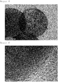
FIG. 5 and FIG. 6 are TEM images photographing a Si@C composite prepared in Example 1 of the present invention. -
FIG. 7 is a graph showing a result of Raman pattern analysis on a Si@C composite prepared in Example 1 of the present invention. -
FIG. 8 is a graph showing a result of XRD analysis on a Si@C composite prepared in Example 1 of the present invention. -
FIG. 9 is a SEM image photographing SiO2 prepared in Comparative Example 1 of present invention. -
FIG. 10 andFIG. 11 are TEM images photographing Si@mC prepared in comparative examples of the present invention. -
FIG. 12 is a SEM image photographing SiO2 prepared in Example 2 of present invention. -
FIG. 13 is a TEM image photographing a Si@mC composite prepared in Example 2 of the present invention. -
FIG. 14 is a graph showing results of capacity property and rate-limiting property experiments according to Comparative Example 1 of the present invention. -
FIG. 15 is a graph showing results of capacity property and rate-limiting property experiments according to Example 1 of the present invention. -
FIG. 16 is a graph showing results of capacity property and rate-limiting property experiments according to Comparative Example 2 of the present invention. -
FIG. 17 is a graph showing results of capacity property and rate-limiting property experiments according to Example 2 of the present invention. -
FIG. 18 is a mimetic diagram illustrating a heat treatment process of the present invention. -
FIG. 19 is a graph showing changes in the XRD measurement results of Comparative Example 1 and Example 1 of the present invention. -
FIG. 20 is a graph showing changes in the XRD measurement results of Comparative Example 2 and Example 2 of the present invention. - Hereinafter, the present invention will be described in detail with reference to accompanying drawings so that those skilled in the art may readily implement the present invention. However, the present invention may be implemented in various different forms, and is not limited to the present specification.
- In the drawings, parts not relevant to the descriptions are not included in order to clearly describe the present invention, and like reference numerals are used for like elements throughout the specification. In addition, sizes and relative sizes of constituents presented in the drawings are unrelated to actual scales, and may be reduced or exaggerated for clarity of the descriptions.
- A particle with a yolk-shell structure of the present invention includes a carbon shell; and a silicon (Si) core provided inside the carbon shell.
- In the present invention, the structure of the yolk-shell particle means, as a term derived from an egg, a structure having empty space between the core and the shell as an egg has a structure in the order of a yolk, a white and a shell. For this, at least a part of the shell of the particle with a yolk-shell structure of the present invention is spaced apart from the core.
- In the present invention, the yolk-shell particle may be prepared through a process as in
FIG. 1 , and this will be examined in detail in a method for preparing a yolk-shell particle to describe later. - In the particle with a yolk-shell structure of the present invention, the particle with a yolk-shell structure may have a micropore particle volume of 0.15 cm3/g or less, preferably 0.05 cm3/g or less, more preferably 0.03 cm3/g or less, and most preferably 0.001 cm3/g or less. When the particle with a yolk-shell structure has a micropore particle volume of greater than 0.15 cm3/g, an electrolyte liquid readily penetrates causing a problem of decreasing capacity retention rate and first cycle Coulombic efficiency when used in a battery.
- In the particle with a yolk-shell structure of the present invention, the pore volume may be measured using common methods used in the industry, and may preferably be measured using BEL mini equipment of BEL.
- In the particle with a yolk-shell structure of the present invention, the particle with a yolk-shell structure may have a specific surface area of 600 m2/g or less, preferably 50 m2/g to 600 m2/g, and most preferably 50 m2/g to 120 m2/g. When the specific surface area range is greater than 600 m2/g, a contact surface with an electrolyte increases increasing probability of causing side reactions with the electrolyte, which causes a problem of decreasing initial efficiency.
- In addition, in the particle with a yolk-shell structure of the present invention, the carbon shell may have a mesopore size of 2 nm or less. The mesopore size being greater than 2 nm may cause a problem of decreasing capacity retention rate and first cycle Coulombic efficiency when used in a battery since an electrolyte liquid readily penetrates.
- In addition, the yolk-shell particle may be prepared through, after going through a process as in
FIG. 1 , a process as inFIG. 18 in the present invention, and the process will be examined in detail in a method for preparing a yolk-shell particle to describe later. - When prepared as above, the size of the silicon (Si) particle in the core provided inside the carbon shell may be 20 nm or greater, preferably from 30 nm to 150 nm, and more preferably from 30 nm to 100 nm in the particle with a yolk-shell structure of the present invention. The silicon particle size being less than 20 nm may cause a problem of decreasing first cycle Coulombic efficiency as the specific surface area increases.
- When prepared as above, the particle with a yolk-shell structure of the present invention may have a specific surface area of 150 m2/g or less, preferably 100 m2/g or less, and most preferably 30 m2/g to 100 m2/g. When the specific surface area increases, a contact area with an electrolyte increases increasing probability of causing side reactions with the electrolyte, which causes a problem of decreasing initial efficiency.
- The particle with a yolk-shell structure of the present invention is prepared through (a) preparing a silica-carbon core-shell particle by forming a carbon shell on silica (SiO2) ; (b) reducing a pore size of the carbon shell of the particle formed in (a); (c) partially etching the silica (SiO2) inside the particle having its pore size reduced in (b); and (d) preparing a particle with a yolk-shell structure through magnesiothermic reduction, and this may be schematically illustrated through
FIG. 1 . - In addition, after d), e) growing a size of a silicon (Si) particle inside the core through heat treating the particle with a yolk-shell structure magnesiothermic reduced in (d) may be further performed in the preparation, and this may be schematically illustrated through
FIG. 18 . - First, the method for preparing a particle with a yolk-shell structure of the present invention includes (a) preparing a silica-carbon core-shell particle by forming a carbon shell on silica (SiO2).
- Silica used in (a) is not particularly limited, but preferably, target size SiO2 is synthesized using a Stober preparation method commonly used in the industry, and preferably, silica having a size of 100 nm to 1,500 nm may be used. As one preferred example, SiO2 having a size of 140 nm is synthesized, and then grown to 300 nm, or SiO2 having a size of 600 nm is synthesized, and then grown to 1 um to be used. After that, the SiO2 surface is polymer coated, and although the polymer is not particularly limited as long as it is a polymer capable of carbonizing a silica surface, cetyltrimethylammonium bromide (CTAB) and the like may be preferably mixed to a polymer precursor such as resorcinol-formaldehyde. After such polymer coating, a silica-carbon core-shell particle (SiO2@C) may be synthesized by carbonizing for 1 hour to 5 hours at 500°C to 1000°C under the N2 atmosphere.
- Next, the method for preparing a particle with a yolk-shell structure of the present invention includes (b) reducing a pore size of the carbon shell of the particle formed in (a).
- In (b), the silica-carbon core-shell particle may be carbonized after infiltrated with phenol in order to reduce the pore size of the carbon shell.
- The amount of the infiltrated phenol may be from 100% to 300% of the pore volume of the silica-carbon core-shell particle (SiO2@C).
- A method of carbonizing the silica-carbon core-shell particle (SiO2@C) is not particularly limited as long as it is a method capable of reducing a pore size of a carbon shell, however, the carbonization may be preferably performed using a method of polymerizing for 3 hours at 90°C using NH3 fume, then, under the nitrogen atmosphere, maintaining a temperature raising rate of 5°C per minute up to 800°C, and maintaining the temperature for 3 hours when reaching the corresponding temperature.
- When capable of reducing a pore size of the carbon shell as in (b), pores of the carbon shell hardly exist unlike existing particles having mesopores in a carbon shell as in
FIG. 2 , and an electrolyte liquid is difficult to penetrate into the particles, which leads to advantages of enhancing a capacity retention rate and enhancing cycle retaining capacity when used in a battery. - In the particle with a yolk-shell structure of the present invention prepared as above, the particle with a yolk-shell structure may have a micropore particle volume of 0.15 cm3/g or less, preferably 0.05 cm3/g or less, more preferably 0.03 cm3/g or less, and most preferably 0.001 cm3/g or less.
- In addition, in the particle with a yolk-shell structure of the present invention prepared as above, the particle with a yolk-shell structure may have a specific surface area of 600 m2/g or less, preferably 50 m2/g to 600 m2/g, and most preferably 50 m2/g to 120 m2/g.
- After that, the method for preparing a particle with a yolk-shell structure of the present invention includes (c) partially etching the silica (SiO2) inside the particle having its pore size reduced in (b).
- In (c), the SiO2 is partially etched in order to secure free space required for charge and discharge.
- For such partial etching, the silica (SiO2) inside the particle having its pore size reduced in (b) is treated with sodium hydroxide (NaOH) to etch a part of the silica (SiO2) inside the core-shell particle.
- By removing a part of the SiO2 through reacting the silica-carbon core-shell particle with sodium hydroxide, free space required for charge and discharge is formed, and this may perform a role of free space preventing the core-shell structure from being broken when volume reduction and expansion occur during a magnesiothermic reduction reaction of the following (d).
- After that, the method for preparing a particle with a yolk-shell structure of the present invention includes (d) preparing a particle with a yolk-shell structure through magnesiothermic reduction.
- In (d), magnesiothermic reduction is performed to reduce the silica (SiO2) inside the particle.
- For this, Si and MgO are produced by reacting the silica (SiO2) inside the silica-carbon core-shell particle (SiO2@C) with Mg after (c).
- When reacting the SiO2 and Mg as above, Si and MgO are produced by a reduction reaction. Herein, molar numbers of the SiO2 before the reduction and the Si after the reduction are the same, and the reaction may be represented by the following
Equation 1.
- As the reaction progresses, the Si and MgO volumes become larger than the SiO2 volume by a difference in the density according to
Equation 1. - In addition, the produced MgO has a molar number corresponding to twice the SiO2, and the volume after the reaction is VSi +VMgO, which is approximately 1.26 times compared to the SiO2. Herein, empty space required for volume expansion needs to be provided by controlling the SiO2 size through sodium hydroxide, and the volume expanding during charge and discharge may be calculated by controlling the volume of the empty space and the volume of the MgO to be removed later through acid treatment to be 3 times of the Si volume.
- Through such a method, a maximum SiO2 size required for 300% volume expansion during Si charge and discharge may be obtained, and this is represented by the following
Equation 2.
- In addition, byproducts such as Mg2Si or SiC are readily produced in the reaction between SiO2@C and Mg in Step 3, and an optimum condition needs to be identified for the reaction.
- In order to reduce the production of byproducts such as Mg2Si or SiC, the equivalent amount of the introduced Mg is preferably 2.5 or less, and the amount of the introduced SiO2@C, needs to be 40 mg or less when the SiO2@C size is from 200 nm to 500 nm, and needs to be 100 mg or less when the SiO2@C size is from 500 nm to 1 um based on one reactor in order to reduce the production of SiC.
- In (d), the magnesiothermic reduction reaction may be progressed after sealing a container with a lid in order to prevent the loss of vaporized Mg as much as possible. Specifically, the reaction is progressed at 400°C to 600°C with a temperature raising rate of 3°C/min to 7°C/min under the Ar atmosphere. In addition, after the thermic reduction reaction is finished, the remaining MgO may be removed using an acid component, and may preferably be removed using a strong acid such as hydrochloric acid.
- After that, the method for preparing a particle with a yolk-shell structure of the present invention includes (e) growing a size of a silicon (Si) particle inside the core through heat treating the particle with a yolk-shell structure magnesiothermic reduced in (d). The concept of e) may be presented as in
FIG. 18 . - In (e), the size of the silicon (Si) particle inside the core may grow by raising a temperature at a temperature raising rate of 2°C/min to 10°C/min, and performing heat treatment for 12 hours to 36 hours at a temperature of 700°C to 1200°C.
- In the heat treatment of (e), the heat treatment in (e) is preferably progressed at a temperature of 700°C to 900°C when the size of the silica (SiO2) used in (a) is greater than or equal to 100 nm and less than 700 nm.
- In addition, in the heat treatment of (e), the heat treatment in (e) is preferably progressed at a temperature of 900°C to 1200°C when the size of the silica (SiO2) used in (a) is greater than or equal to 700 nm and less than or equal to 1,500 nm. Not satisfying the above-mentioned temperature may cause a problem in the silicon particle growth
- The size of the silicon (Si) particle grown as above may be 20 nm or greater, preferably from 30 nm to 150 nm, and more preferably from 30 nm to 100 nm. The silicon particle size being less than 20 nm may cause a problem of decreasing first cycle Coulombic efficiency as the specific surface area increases.
- In addition, the particle with a yolk-shell structure may have a specific surface area of 150 m2/g or less, preferably 150 m2/g or less, and more preferably 30 m2/g to 100 m2/g. The specific surface area range being greater than 150 m2/g may cause a problem of decreasing first cycle Coulombic efficiency.
- The particle with a yolk-shell structure provided in the present invention may be preferably used as a negative electrode material of a negative electrode for a lithium secondary battery.
- The negative electrode includes a negative electrode active material formed on a negative electrode current collector, and as the negative electrode active material, the particle with a yolk-shell structure prepared according to the present invention is used.
- The negative electrode current collector may specifically be selected from the group consisting of copper, stainless steel, titanium, silver, palladium, nickel, alloys thereof and combinations thereof. The stainless steel may be surface treated with carbon, nickel, titanium or silver, and aluminum-cadmium alloys may be used as the alloy. In addition thereto, baked carbon, nonconductive polymers of which surface is treated with a conductor, conductive polymers or the like may also be used.
- The negative electrode may further include a binder resin, a conductor, a filler, other additives and the like.
- The binder resin is used for binding of the electrode active material and the conductor and for binding on the current collector. Nonlimiting examples of such a binder resin may include polyvinylidene fluoride (PVDF), polyvinyl alcohol (PVA), polyacrylic acid (PAA), polymethacrylic acid (PMA), polymethyl methacrylate (PMMA) polyacrylamide (PAM), polymethacrylamide, polyacrylonitrile (PAN), polymethacrylonitrile, polyimide (PI), alginic acid, alginate, chitosan, carboxymethylcellulose (CMC), starch, hydroxypropylcellulose, regenerated cellulose, polyvinyl pyrrolidone, tetrafluoroethylene, polyethylene, polypropylene, an ethylene-propylene-diene polymer (EPDM), a sulfonated-EPDM, styrene-butadiene rubber (SBR), fluorine rubber, various copolymers thereof and the like.
- The conductor is used for further enhancing conductivity of the electrode active material. Such a conductor is not particularly limited as long as it has conductivity with inducing chemical changes to the corresponding battery, and for example, graphite such as natural graphite or artificial graphite; carbon black such as carbon black, acetylene black, ketjen black, channel black, furnace black, lamp black and thermal black; conductive fibers such as carbon fibers or metal fibers; fluorocarbon, aluminum and metal powders such as nickel powder; conductive whiskers such as zinc oxide and potassium titanate; conductive metal oxides such as titanium oxide; polyphenylene derivatives, and the like may be used.
- As one embodiment of the present invention, a lithium secondary battery includes the negative electrode described above; a positive electrode; and an electrolyte.
- The lithium secondary battery according to the present invention includes a positive electrode, a negative electrode, and a separator and an electrolyte provided therebetween, and includes the particle with a yolk-shell structure prepared according to the present invention as a negative electrode active material.
- The particle with a yolk-shell structure prepared according to the present invention may mitigate capacity degeneration caused by silicon volume expansion, and exhibits excellent electrical conductivity and capacity retention rate.
- Constitutions of the positive electrode, the negative electrode, the separator and the electrolyte of the lithium secondary battery are not particularly limited in the present invention, and follow constitutions known in the art.
- The positive electrode is used including a positive electrode active material formed on a positive electrode current collector, and the positive electrode current collector is not particularly limited as long as it has high conductivity without inducing chemical changes to the corresponding battery, and for example, stainless steel, aluminum, nickel, titanium, baked carbon, or aluminum or stainless steel of which surface is treated with carbon, nickel, titanium, silver or the like may be used. Herein, the positive electrode current collector may use various forms such as films, sheets, foil, nets, porous bodies, foams or non-woven fabrics having micro-unevenness formed on its surface so as to increase adhesive strength with the positive electrode active material.
- As the positive electrode active material forming the electrode layer, all positive electrode active materials usable in the art may be used. Specific examples of such a positive electrode active material may include lithium cobalt-based oxides such as LiCoO2; lithium manganese-based oxides such as Li1+xMn2-xO4 (herein, x is from 0 to 0.33), LiMnO3, LiMn2O3 or LiMnO2; lithium copper oxides such as Li2CuO2; vanadium oxide such as LiV3O8, LiFe3O4, V2O5 or Cu2V2O7; lithium nickel-based oxides represented by LiNi1-xMxO2 (herein, M=Co, Mn, Al, Cu, Fe, Mg, B or Ga, and x=0.01 to 0.3); lithium manganese composite oxides represented by LiMn2-xMxO2 (herein, M=Co, Ni, Fe, Cr, Zn or Ta, and x=0.01 to 0.1) or Li2Mn3MO8 (herein, M=Fe, Co, Ni, Cu or Zn) ; lithium-nickel-manganese-cobalt-based oxides represented by Li (NiaCObMnc) O2 (herein, 0 < a < 1, 0 < b < 1, 0 < c < 1, and a+b+c=1); vanadium oxides such as LiV3O8, LiFe3O4, V2O5 or Cu2V2O7; sulfur or disulfide compounds; phosphates such as LiFePO4, LiMnPO4, LiCoPO4 or LiNiPO4; Fe2 (MoO4)3 and the like, but are not limited thereto.
- Herein, the electrode layer may further include, in addition to the positive electrode active material, a binder resin, a conductor, a filler, other additives and the like.
- The binder resin is used for binding of the electrode active material and the conductor and for binding on the current collector. Nonlimiting examples of such a binder resin may include polyvinylidene fluoride (PVDF), polyvinyl alcohol (PVA), polyacrylic acid (PAA), polymethacrylic acid (PMA), polymethyl methacrylate (PMMA) polyacrylamide (PAM), polymethacrylamide, polyacrylonitrile (PAN), polymethacrylonitrile, polyimide (PI), alginic acid, alginate, chitosan, carboxymethylcellulose (CMC), starch, hydroxypropylcellulose, regenerated cellulose, polyvinyl pyrrolidone, tetrafluoroethylene, polyethylene, polypropylene, an ethylene-propylene-diene polymer (EPDM), a sulfonated-EPDM, styrene-butadiene rubber (SBR), fluorine rubber, various copolymers thereof and the like.
- The conductor is used for further enhancing conductivity of the electrode active material. Such a conductor is not particularly limited as long as it has conductivity with inducing chemical changes to the corresponding battery, and for example, graphite such as natural graphite or artificial graphite; carbon black such as carbon black, acetylene black, ketjen black, channel black, furnace black, lamp black and thermal black; conductive fibers such as carbon fibers or metal fibers; fluorocarbon, aluminum and metal powders such as nickel powder; conductive whiskers such as zinc oxide and potassium titanate; conductive metal oxides such as titanium oxide; polyphenylene derivatives, and the like may be used.
- As the negative electrode, the negative electrode of the present invention described above may be used.
- The separator may be formed with a porous base, and as the porous base, porous bases commonly used in electrochemical devices may all be used. Examples thereof may include polyolefin-based porous membranes or non-woven fabrics, but are not limited thereto.
- The separator may be a porous base formed with any one selected from the group consisting of polyethylene, polypropylene, polybutylene, polypentene, polyethylene terephthalate, polybutylene terephthalate, polyester, polyacetal, polyamide, polycarbonate, polyimide, polyetheretherketone, polyether sulfone, polyphenylene oxide, polyphenylene sulfide and polyethylene naphthalate, or a mixture of two or more types thereof.
- The electrolyte liquid of the lithium secondary battery is, as a lithium salt-containing non-aqueous electrolyte liquid, formed with a lithium salt and a solvent, and as the solvent, non-aqueous organic solvents, organic solid electrolytes, inorganic solid electrolytes and the like are used.
- The lithium salt is a material to be favorably dissolved in the non-aqueous electrolyte liquid, and examples thereof may include LiCl, LiBr, LiI, LiClO4, LiBF4, LiB10Cl10, LiPF6, LiAsF6, LiSbF6, LiAlCl4, LiSCN, LiC4BO8, LiCF3CO2, LiCH3SO3, LiCF3SO3, LiN(SO2CF3)2, LiN(SO2C2F5)2, LiC4F9SO3, LiC(CF3SO2)3, (CF3SO2)·2NLi, chloroborane lithium, lower aliphatic carboxylic acid lithium, lithium tetraphenylborate, lithium imide and the like.
- Examples of the non-aqueous organic solvent may include aprotic organic solvents such as N-methyl-2-pyrrolidinone, propylene carbonate, ethylene carbonate, butylene carbonate, dimethyl carbonate, diethyl carbonate, ethylmethyl carbonate, gamma-butyrolactone, 1,2-dimethoxyethane, 1,2-diethoxyethane, tetrahydroxy franc, 2-methyltetrahydrofuran, dimethyl sulfoxide, 1,3-dioxolane, 4-methyl-1,3-dioxene, diethyl ether, formamide, dimethylformamide, dioxolane, acetonitrile, nitromethane, methyl formate, methyl acetate, phosphoric acid triester, trimethoxymethane, dioxolane derivatives, sulfolane, methylsulfolane, 1,3-dimethyl-2-imidazolidinone, propylene carbonate derivatives, tetrahydrofuran derivatives, ether, methyl propionate or ethyl propionate.
- As the organic solid electrolyte, for example, polyethylene derivatives, polyethylene oxide derivatives, polypropylene oxide derivatives, phosphoric acid ester polymers, polyagitation lysine, polyester sulfide, polyvinyl alcohol, polyvinylidene fluoride, polymers including an ionic dissociation group, and the like may be used.
- As the inorganic solid electrolyte, for example, nitrides, halides, sulfates and the like of Li such as Li3N, LiI, Li5NI2, Li3N-LiI-LiOH, LiSiO4, LiSiO4-LiI-LiOH, Li2SiS3, Li4SiO4, Li4SiO4-LiI-LiOH or Li3PO4-Li2S-SiS2 may be used.
- In addition, with the purpose of improving charge and discharge properties, flame retardancy and the like, the non-aqueous electrolyte liquid may further include other additives. Examples of the additive may include pyridine, triethylphosphite, triethanolamine, cyclic ether, ethylenediamine, n-glyme, hexaphosphoric acid triamide, nitrobenzene derivatives, sulfur, quinoneimine dyes, N-substituted oxazolidinone, N,N-substituted imidazolidine, ethylene glycol dialkyl ether, ammonium salts, pyrrole, 2-methoxyethanol, aluminum trichloride, fluoro-ethylene carbonate (FEC), propene sultone (PRS), vinylene carbonate (VC) and the like.
- The lithium secondary battery according to the present invention may go through lamination (stack) and folding processes of a separator and an electrode in addition to winding, a general process. In addition, the battery case may be a cylinder-type, a square-type, a pouch-type, a coin-type or the like.
- Hereinafter, preferred examples are provided in order to illuminate the present invention, however, the following examples are for illustrative purposes only, and it is obvious to those skilled in the art that various changes and modifications may be made within the category and technological ideas of the present invention, and such changes and modifications also fall within the scope of the attached claims.
- After synthesizing SiO2 having an average particle size of 140 nm using a stober method, the 140 nm SiO2 was grown to 300 nm. The prepared 300 nm SiO2 was photographed using a scanning electron microscope (SEM), and this is shown in
FIG. 3 . - After that, 0.5 g of the SiO2 was dispersed into 380 mL of water, then 5 mL of 7.5 mM cetyltrimethylammonium bromide (CTAB) was introduced thereto, and after sufficiently mixing the result, 0.2 mL of ammonia was introduced thereto. After that, a solution mixing 200 mg of resorcinol and 0.2 mL of formaldehyde with 5 mL of water was added thereto, and the result was reacted for 24 hours for polymer coating.
- After that, the SiO2@polymer composite was carbonized for 3 hours at a temperature of 800°C under the N2 atmosphere to synthesize a SiO2@C core-shell structure.
- In addition, a result of Raman pattern analysis on the prepared 300 nm SiO2@C core-shell is shown in
FIG. 6 . - A micropore volume of the prepared SiO2@C core-shell was measured, and the results are shown in Table 5 to describe later.
- A pore blocking process for reducing a pore size of the carbon of the prepared SiO2@C core-shell was progressed.
- To the prepared SiO2@C core-shell, phenol corresponding to 150% of the pore volume was infiltrated. After that, the result was polymerized for 3 hours at 90°C using NH3 fume, and, under the nitrogen atmosphere, carbonization was progressed by maintaining a temperature raising rate of 5°C per minute up to 800°C, and maintaining the temperature for 3 hours when reaching the corresponding temperature.
- The SiO2 was partially etched in order to secure free space required for charge and discharge.
- For the partial etching, sodium hydroxide (NaOH) was added to the SiO2@C core-shell prepared in
Step 2. By adding sodium hydroxide as above, a part of the silica (SiO2) inside the SiO2@C core-shell was etched, and empty space was formed inside the SiO2@C core-shell therethrough. Such empty space formation may perform a role of free space preventing the core-shell structure from being broken when volume reduction and expansion occur during a magnesiothermic reduction reaction of the following Step 4. - On the SiO2@C core-shell prepared in Step 3, magnesiothermic reduction was progressed using a method of vaporizing magnesium through a gas solid reaction in a w24xL32xh17 mm-sized alumina reactor with a lid, and then reacting the result with the SiO2@C core-shell. Herein, the equivalent amount of the introduced Mg was 1.5, 2.0 and 2.5, and the amount of the introduced SiO2@C was 30 mg, 40 mg and 50 mg.
- The reaction was progressed in an alumina boat with a lid while blocking the gap using gypsum in order to prevent the loss of vaporized Mg as much as possible, and specifically, the thermic reduction reaction was progressed at 600°C with a temperature raising rate of 5°C /min under the Ar atmosphere.
- After finishing the thermic reduction reaction, the remaining MgO was removed using HCl, and finally, a Si@C composite with a yolk-shell structure was obtained.
- First, production of byproducts depending on the equivalent amount of the introduced Mg was identified.
[Table 1] Equivalent Amount of Introduced Mg Weight of Introduced SiO2@C (mg) Result Experiment 1 1.5 30 Mg2Si Production Not Identified Experiment 2 2.0 30 Mg2Si Production Not Identified Experiment 3 2.5 30 Mg2Si Production Identified - As in Table 1, production of byproducts was identified when the equivalent amount of Mg was 2.5 or greater.
- Next, production of byproducts depending on the weight of the introduced SiO2@C was identified.
[Table 2] Equivalent Amount of Introduced Mg Weight of Introduced SiO2@C (mg) Result Experiment 4 2.0 30 SiC Production Not Identified Experiment 5 2.0 40 SiC Production Not Identified Experiment 6 2.0 50 SiC Production Identified - The SiC is a thermodynamically stable material produced at an interface between SiO2 and C, and heat is generated when SiO2 is reduced to Si. As shown in Table 2, it was seen that SiC production dominated as the sample amount increased since the amount of heat generated increased.
- In addition, the prepared Si@C composite with a yolk-shell structure was photographed using a transmission electron microscope (TEM), and the results are shown in
FIG. 5 and FIG. 6 . - Through the transmission electron microscope measurements of
FIG. 5 and FIG. 6 , it was identified that, unlike Comparative Example 1 ofFIG. 10 , a graphitic layer and a porous Si structure were produced in the carbon shell after the reaction of Mg as the Si@C with a yolk-shell structure was synthesized using a magnesium reaction in Example 1. - In addition, in order to examine physical changes in the carbon after the magnesium reaction, a Raman pattern analysis was performed on the Si@C composite with a yolk-shell structure prepared above, and the results are shown in
FIG. 7 , and an X-ray diffraction analysis (XRD) was progressed in the same manner, and the results are shown inFIG. 8 . - Through comparing the results of Raman spectrum analyses, it was identified that the Si@C composite of
FIG. 7 exhibited a graphitic property of carbon better compared to the SiO2@C composite ofFIG. 4 (ID/IG: 1.01→0.95) . - The Si@C-structured yolk-shell material prepared in Step 4 was reacted for 24 hours after reaching 800°C by raising a temperature with a temperature raising rate of 5°C/min under the Ar atmosphere.
- An X-ray diffraction (XRD) analysis was progressed on the yolk-shell before the heat treatment (Comparative Example 1) and after the heat treatment (Example 1) in Step 5, and the results are shown in
FIG. 19 . - The black graph shows the result of the XRD analysis on the yolk-shell particle before the heat treatment, and the blue graph shows the result of the XRD analysis on the yolk-shell particle after the heat treatment. Through
FIG. 19 , it was seen that the Si crystal size increased from 16.1 nm to 31.4 nm. - Preparation was made in the same manner as in Example 1 except that SiO2 having an average particle size of 600 nm was used and grown to 1 µm instead of using SiO2 having an average particle size of 140 nm. The prepared 1 µm SiO2 was photographed using a scanning electron microscope (SEM), and the result is shown in
FIG. 12 . - Preparation was made in the same manner as in Example 1.
- Preparation was made in the same manner as in Example 1.
- Preparation was made in the same manner as in Example 1 except that the amount of the introduced SiO2 was 50 mg, 100 mg and 110 mg.
- In addition, the prepared Si@C yolk shell was photographed using a transmission electron microscope (TEM), and the result is shown in
FIG. 13 . - As in Example 1, production of byproducts depending on the equivalent amount of the introduced Mg and the weight of the introduced SiO2@C was identified.
- First, production of byproducts depending on the equivalent amount of the introduced Mg was identified.
[Table 3] Equivalent Amount of Introduced Mg Weight of Introduced SiO2@C (mg) Result Experiment 7 1.5 50 Mg2Si Production Not Identified Experiment 8 2.0 50 Mg2Si Production Not Identified Experiment 9 2.5 50 Mg2Si Production Identified - As in Table 3, production of Mg2Si was identified when the equivalent amount of Mg was 2.5 or greater.
- Next, production of byproducts depending on the weight of the introduced SiO2@C was identified.
[Table 4] Equivalent Amount of Introduced Mg Weight of Introduced SiO2@C (mg) Result Experiment 10 2.0 50 SiC Production Not Identified Experiment 11 2.0 100 SiC Production Not Identified Experiment 12 2.0 110 SiC Production Identified - As shown in Table 4, it was also seen in Example 2 that SiC production dominated as the sample amount increased since the amount of heat generated increased.
- The Si@C-structured yolk-shell material prepared in Step 4 was reacted for 24 hours after reaching 1000°C by raising a temperature with a temperature raising rate of 5°C/min under the Ar atmosphere.
- An X-ray diffraction (XRD) analysis was progressed on the yolk-shell before the heat treatment (Comparative Example 2) and after the heat treatment (Example 2) in Step 5, and the results are shown in
FIG. 20 . - The black graph shows the result of the XRD analysis on the yolk-shell particle before the heat treatment, and the blue graph shows the result of the XRD analysis on the yolk-shell particle after the heat treatment. Through
FIG. 20 , it was seen that the Si crystal size increased from 17.1 nm to 30.0 nm. - After synthesizing 140 nm SiO2 in the same manner as in the Example described above, 200 nm SiO2 was synthesized through a growth method. After that, 3 g of the SiO2 was ultrasonic dispersed into a solution mixing 108 g of EtOH and 224 g of DI water, and 1.11 g of CTAB was further introduced and dissolved therein. The result was stirred for 10 minutes, 3 g of ammonia and 2 g of TEOS were introduced thereto, and the result was reacted for 16 hours to additionally synthesize a shell having 2 nm mesopores on the existing SiO2 surface. After the reaction, the result was purified using EtOH, and after drying the material, CTAB in the pores was removed through calcination for 5 hours at 700°C in a box furnace. In order to introduce a polymer that becomes a precursor of carbon to the synthesized material, 2 g of AlCl36H2O per 2 g of SiO2@mSiO2 was dispersed into a mixed solution of 20 mL of DI water and 20 mL of EtOH for 2 hours through ultrasonic dispersion. Herein, Al was doped on the pores of the SiO2@mSiO2, and a polymer reaction was progressed utilizing this as a catalytic site. Per 200 mg of the synthesized Al-SiO2@mSiO2, 95 mg of phenol and 100 mg of paraformaldehyde were used. After introducing the Al-SiO2@mSiO2 material to a sealable container by being spread widely, phenol and para-formaldehyde were each placed in a small plastic or aluminum container, and introduced to the container including the Al-SiO2@mSiO2. After sealing the container, the result was reacted for 12 hours in a 100°C oven, and then carbonized for 3 hours at 800°C under the nitrogen atmosphere. The phenol and the para-formaldehyde were vaporized at a temperature of 80°C or higher resulting in a regioselective polymer reaction at the Al catalytic site, which made selective polymer synthesis possible inside the pores. After that, a SiO2@mC material was synthesized by progressing a partial etching process in the same manner as in Example 1.
- The SiO2 produced in the comparative example was photographed using a scanning electron microscope (SEM), and the result is shown in
FIG. 9 . - A reduction process was progressed as disclosed in "J. Phys. Chem. C 2015, 119, 10255", an existing technology.
- Specifically, SiO2@C and an excess amount of Mg were used (SiO2:Mg=1:4 mol ratio) in order to prevent SiC production, and Mg2Si was reduced to Si using a H2/Ar gas mixture.
- As above, magnesiothermic reduction using an existing carbon-silicon composite may produce SiC (silicon carbide) thermodynamically stable compared to Si.
- In addition, the prepared Si@mC composite with a core shell structure was photographed using a transmission electron microscope (TEM), and the results are shown in
FIG. 10 andFIG. 11 . - Preparation was progressed in the same manner as in Example 1 except that Step 5 was not included.
- Preparation was progressed in the same manner as in Example 2 except that Step 5 was not included.
- Pore structures of the SiO2@C prepared in Example 1 and the SiO2@mC (yolk-shell structure having 2 nm to 3 nm mesopores) prepared in Comparative Example 1 were measured using BEL mini nitrogen adsorption equipment manufactured by BEL, and the results are shown in
FIG. 12 , and a pore structure of the Si@C prepared in Example 1 (yolk-shell structure synthesized using SiO2@C) is also shown inFIG. 13 . - In addition, nitrogen adsorption experiments were progressed on a specific surface area (SBET), a total volume (Vtot) and a pore volume (Vmicro) of the SiO2@C, the SiO2@mC and the Si@mC using BEL mini nitrogen adsorption equipment manufactured by BEL, the results were measured, and shown in the following Table 5.
[Table 5] Subject SBET (m2/g) Vtot (cm3/g) Vmicro (cm3/g) SiO2@mC 711 0.956 0.180 SiO2@C 124.7 0.06 0.046 Si@C 116 0.53 0 - Through
FIG. 12, FIG. 13 and Table 5, it was identified that, by synthesizing the Si@C composite with a yolk-shell structure using a magnesium reaction, the micropore volume of the SiO2@C material before and after the magnesium reaction was reduced after the reaction (0.046 cm3/g→0.0 cm3/g), and through this, it was seen that the pore structure of the amorphous carbon changed. - For the yolk-shell structures prepared in Examples 1 and 2 and Comparative Examples 2 and 3, the specific surface area and the particle size were measured, and the results are shown in the following Table 6.
- As for the specific surface area, nitrogen adsorption experiments were progressed using BEL mini nitrogen adsorption equipment manufactured by BEL, the results were measured, and shown in the following Table 6.
- In addition, the particle size means an average size that measures diameters of approximately 100 particles using the images obtained through the SEM analyses. This is shown in Table 6.
[Table 6] Subject SBET (m2/g) Si Particle Size (nm) (Crystal Size) Comparative Example 2 (300 nm Si@C)) 116 16.1 Example 1 (300 nm Si@C_heat) 70 31.47 Comparative Example 3 (1 µm Si@C) 180 17.1 Example 2 (1 µm Si@C_heat) 131 30 - Through
FIG. 12, FIG. 13 and Table 6, it was seen that the Si particle size in the Si@C composite with a yolk-shell structure was grown through additional heat treatment. - A battery was manufactured using each of the Si@C composites prepared in Example 1 and Comparative Example 1 as a negative electrode active material.
- First, the Si@C prepared in each of Example 1 and Comparative Example 1: binder (polyamide imide (PAI)):conductor (Super-P) were mixed in a weight ratio of 6: 2:2, and NMP was used as a solvent to prepare slurry.
- The prepared slurry was coated on copper (Cu) foil to a thickness of 40 um using a doctor blade, and in order to increase the binder effect of PAI, heat treatment was performed for 1.5 hours at 350°C under the Ar atmosphere to prepare a negative electrode.
- After that, as for a half-cell in Example 1, a coin 2032 type cell was used, EC:DEC were mixed in 30:70 vol% as an electrolyte liquid,
FEC 10 wt% was used as an additive, and a 1.3 M LiPF6 composition was used as a lithium salt to manufacture a half-cell. - In addition, in Comparative Example 1, a coin 2016 type cell was used as a half-cell, EC:DEC:FEC were mixed in 5:70:25 vol% as an electrolyte liquid, and a 1.5 M LiPF6 composition was used as a lithium salt.
- As for a capacity property experiment, experiments were progressed under a condition of 0.01 V to 1.5 V and 0.1 C at a first cycle, and 0.01 V to 1.0 V and 0.1 C at a second cycle, and from a third cycle after that, experiments were progressed under a condition of 0.01 V to 1.0 V and 0.5 C in order to produce a stable SEI layer. Herein, a 0.02 C cut off current was used in all the cycles.
- A rate-limiting property experiment was all the same as the cycle properties, and progressed under a condition of 0.2 C, 0.5 C, 1 C, 2 C and 5 C for 5 cycles each at a third cycle.
- A capacity property experiment and a rate-limiting property experiment were progressed as disclosed in "J. Phys. Chem. C 2015, 119, 10255", an existing technology.
- Specifically, the capacity property experiment was progressed under a condition of 0.01 V to 1.5 V and 400 mA/g.
- The rate-limiting property experiment and the cycle property were all progressed under a condition of 400 mA/g, 800 mA/g, 1600 mA/g and 3200 mA/g for 10 cycles each.
- Results of the capacity property experiment and the rate-limiting property experiment performed on the battery manufactured in Example 1 are shown in
FIG. 14 andFIG. 15 , respectively, and results of the capacity property experiment and the rate-limiting property experiment performed on the battery manufactured in Comparative Example 1 are shown inFIG. 16 andFIG. 17 , respectively. - In addition, properties of the battery manufactured in Example 1 and the battery manufactured in Comparative Example 1 were compared, and the results are shown in Table 7.
[Table 7] Cryst al Size1 1st Cycl e CE Capacity Retentio n Rate2 Cacp city 3 2 C Capacity Retention Rate4 Thickness During Charge and Discharge6 Comparative Example 1 ( Si@mC) 16.3 45 82.9 896 25.6 - Example 1 (Si@C) 16.1 70 96.5 1390 97.5 67->73 (9%) (1: unit was nm
2: based on @50 cycle
3: based on @50cycle (mAh/g)
4: with respect to 0.5 C
5: unit was um. Based on @50 cycle (discharge)
6: unit was um. Based on @50 (discharge) vs 51 (charge) cycle) - Through Table 7, it was identified that, when using Example 1 of the present invention, a rate-limiting property of high efficiency depending on physical properties of carbon and material structures was obtained.
- Particularly, 2 C capacity retention rate was 97.5% with respect to 0.5 C, which was significantly different compared to Comparative Example 1 that was 25.6%, and this is expected to be caused by graphitic physical properties of carbon and a mesoporous structure of Si of the present invention.
- In addition, as for the changes in the electrode thickness caused by the yolk shell structure, it was identified that, in the present invention, the electrode thickness when discharging after a 50th cycle and the electrode thickness when charging at a 51st cycle had a 9% increase.
- In the Si@C composite with a yolk shell structure prepared by Example 1 of the present invention, it was seen that local heating was generated through magnesiothermic reduction, an exothermic reaction, and noncrystalline carbon changed to graphitic carbon at a high temperature, which reduced porosity and increased electrical properties. Through this, it was seen to have a positive effect on electrochemical properties when used in a battery.
- On the other hand, in the Si@mC composite prepared by Comparative Example 1, it was seen that porosity increased by the use of carbon having a relatively large pore size, which resultantly smoothed electrolyte penetration and declined electrochemical performance.
- A battery was manufactured using each of the Si@C composites prepared in Example 1, Example 2, Comparative Example 2 and Comparative Example 3 as a negative electrode active material.
- First, the Si@C prepared in each of Example 1, Example 2, Comparative Example 2 and Comparative Example 3: binder (polyamide imide (PAI)):conductor (Super-P) were mixed in a weight ratio of 6:2:2, and NMP was used as a solvent to prepare slurry.
- The prepared slurry was coated on copper (Cu) foil to a thickness of 40 um using a doctor blade, and in order to increase the binder effect of PAI, heat treatment was performed for 1.5 hours at 350°C under the Ar atmosphere to prepare a negative electrode.
- After that, as for a half-cell, a coin 2032 type cell was used, EC:DEC were mixed in 30:70 vol% as an electrolyte liquid,
FEC 10 wt% was used as an additive, and a 1.3 M LiPF6 composition was used as a lithium salt to manufacture a half-cell. -
- 1) As for a capacity property experiment, experiments were progressed under a condition of 0.01 V to 1.5 V and 0.1 C at a first cycle, and 0.01 V to 1.0 V and 0.1 C at a second cycle, and from a third cycle after that, experiments were progressed under a condition of 0.01 V to 1.0 V and 0.5 C in order to produce a stable SEI layer. Herein, a 0.02 C cut off current was used in all the cycles.
- 2) A rate-limiting property experiment was all the same as the cycle properties, and progressed under a condition of 0.2 C, 0.5 C, 1 C, 2 C and 5 C for 5 cycles each at a third cycle.
- Results of the capacity property experiment and the rate-limiting property experiment performed on the battery using each of the composites prepared in Example 1 and Comparative Example 2 are shown in
FIG. 14 andFIG. 15 , respectively, and results of the capacity property experiment and the rate-limiting property experiment performed on the battery using each of the composites prepared in Example 2 and Comparative Example 3 are shown inFIG. 16 andFIG. 17 , respectively. - In addition, properties of Examples 1 and 2, and Comparative Examples 2 and 3 were compared, and the results are shown in Table 8.
[Table 8] 1st Cycle CE Capac ity Reten tion Rate2 Cacpc ity3 2 C Capacit y Retenti on Rate4 Change in Thicknes S5 Thickness During Charge and Discharge6 Comparative Example 2 (300 nm Si@C) 70 96.5 1390 97.5 45→58 (28%) 67→73 (9%) Example 1 (300 nm Si@C_heat) 75 94 1257 92.4 43→53 (23%) 53→56 (5%) Comparative Example 3 (1 µm Si@C) 60 97 997 93 48→57 µm (18%) 57→62 (9%) Example 2 (1 µm Si@C_heat) 65 93 1290 - 43→55 (28%) 55→59 (7%) (1: unit was nm
2: based on @50 cycle
3: based on @50cycle (mAh/g)
4: with respect to 0.5 C
5: unit was um. Based on @50 cycle (discharge)
6: unit was um. Based on @50 (discharge) vs 51 (charge) cycle) - When examining
FIG. 14 to FIG. 17 , and Table 8, Coulombic efficiency at the first cycle was 70% in the battery using the composite prepared in Comparative Example 1 (300 nm Si@C), and 60% in the battery using the composite prepared in Comparative Example 2 (1 um Si@C). - When examining the results of the batteries using the composites prepared in Example 1 and Example 2 increasing a Si crystal size through heat treatment and progressing a process decreasing a specific surface area with respect to the batteries using the composites prepared in Comparative Examples 2 and 3, it was seen that first cycle Coulombic efficiency increased by approximately 5% regardless of the yolk-shell structure size.
- In addition, it was identified that the electrode thickness when discharging after the 50th cycle increased by approximately 20% when compared with the electrode thickness before the cycle, and it was identified that a difference between the electrode thickness when discharging after the 50th cycle and the electrode thickness when charging at the 51st cycle increased by less than 10%. Through this, it was seen that changes in the battery volume caused by volume expansion, a disadvantage of existing silicon negative electrode materials, were minimized, and as a result, stable results were obtained in charge and discharge capacity as well.
Claims (23)
- A particle with a yolk-shell structure comprising:a carbon shell; anda silicon (Si) core provided inside the carbon shell,wherein at least a part of the shell is spaced apart from the core, andthe particle with a yolk-shell structure has a micropore volume of 0.15 cm3/g or less.
- The particle with a yolk-shell structure of Claim 1, wherein the particle with a yolk-shell structure has a micropore volume of 0.05 cm3/g or less.
- The particle with a yolk-shell structure of Claim 1, which has a micropore volume of 0.03 cm3/g or less.
- The particle with a yolk-shell structure of Claim 1, which has a micropore volume of 0.001 cm3/g or less.
- The particle with a yolk-shell structure of Claim 1, which has a specific surface area of 600 m2/g or less.
- The particle with a yolk-shell structure of Claim 1, which has a specific surface area of 50 m2/g to 600 m2/g.
- The particle with a yolk-shell structure of Claim 1, which has a specific surface area of 50 m2/g to 120 m2/g.
- The particle with a yolk-shell structure of Claim 1, wherein the carbon shell has a mesopore size of 2 nm or less.
- A particle with a yolk-shell structure comprising:a carbon shell; anda silicon (Si) core provided inside the carbon shell,wherein at least a part of the shell is spaced apart from the core, anda silicon (Si) particle inside the core has a size of 20 nm or greater.
- The particle with a yolk-shell structure of Claim 9, wherein the silicon (Si) particle has a size of 30 nm to 150 nm.
- The particle with a yolk-shell structure of Claim 9, wherein the silicon (Si) particle has a size of 30 nm to 100 nm.
- The particle with a yolk-shell structure of Claim 9, wherein the yolk-shell structure has a specific surface area of 150 m2/g or less.
- The particle with a yolk-shell structure of Claim 9, wherein the yolk-shell structure has a specific surface area of 100 m2/g or less.
- The particle with a yolk-shell structure of Claim 9, wherein the yolk-shell structure has a specific surface area of 30 m2/g to 100 m2/g or less.
- A method for preparing a particle with a yolk-shell structure, the method comprising:(a) preparing a silica-carbon core-shell particle by forming a carbon shell on silica (SiO2);(b) reducing a pore size of the carbon shell of the particle formed in (a);(c) partially etching the silica (SiO2) inside the particle having its pore size reduced in (b); and(d) preparing a particle with a yolk-shell structure through magnesiothermic reduction.
- The method for preparing a particle with a yolk-shell structure of Claim 15, the method further comprising (e) growing a size of a silicon (Si) particle inside the core through heat treating the particle with a yolk-shell structure magnesiothermic reduced in (d).
- The method for preparing a particle with a yolk-shell structure of Claim 15, wherein, in (a), the silica (SiO2) has a size of 100 nm to 1,500 nm.
- The method for preparing a particle with a yolk-shell structure of Claim 15, wherein, in (b), the silica-carbon core-shell particle is carbonized after infiltrated with phenol.
- The method for preparing a particle with a yolk-shell structure of Claim 15, wherein, in (c), a part of the SiO2 is removed by reacting the silica-carbon core-shell particle with sodium hydroxide.
- The method for preparing a particle with a yolk-shell structure of Claim 15, wherein, in (d), Si and MgO are produced by reacting the SiO2 inside the silica-carbon core-shell particle with Mg.
- The method for preparing a particle with a yolk-shell structure of Claim 16, wherein, in (e), the size of the silicon (Si) particle grows by raising a temperature at a temperature raising rate of 2°C/min to 10°C/min, and performing heat treatment for 12 hours to 36 hours at a temperature of 700°C to 1200°C.
- A negative electrode for a lithium secondary battery comprising the particle with a yolk-shell structure of any one of Claims 1 to 14.
- A lithium secondary battery comprising:the negative electrode of Claim 22;a positive electrode; andan electrolyte.
Applications Claiming Priority (3)
| Application Number | Priority Date | Filing Date | Title |
|---|---|---|---|
| KR1020170127273A KR102168350B1 (en) | 2017-09-29 | 2017-09-29 | Yolk-shell particle, manufacturing method thereof, lithium secondary battery comprising the same |
| KR1020170127292A KR102148510B1 (en) | 2017-09-29 | 2017-09-29 | Yolk-shell particle, manufacturing method thereof, lithium secondary battery comprising the same |
| PCT/KR2018/011233 WO2019066402A2 (en) | 2017-09-29 | 2018-09-21 | Yolk-shell structured particles, method for producing same, and lithium secondary battery comprising same |
Publications (2)
| Publication Number | Publication Date |
|---|---|
| EP3648210A2 true EP3648210A2 (en) | 2020-05-06 |
| EP3648210A4 EP3648210A4 (en) | 2020-08-26 |
Family
ID=65903407
Family Applications (1)
| Application Number | Title | Priority Date | Filing Date |
|---|---|---|---|
| EP18862954.7A Pending EP3648210A4 (en) | 2017-09-29 | 2018-09-21 | STRUCTURED CORE-SLEEVE PARTICLES, THE PROCESS FOR THEIR MANUFACTURING AND THIS CONTAINED LITHIUM SECONDARY BATTERY |
Country Status (5)
| Country | Link |
|---|---|
| US (1) | US11999624B2 (en) |
| EP (1) | EP3648210A4 (en) |
| JP (2) | JP7062691B2 (en) |
| CN (2) | CN110892563B (en) |
| WO (1) | WO2019066402A2 (en) |
Families Citing this family (20)
| Publication number | Priority date | Publication date | Assignee | Title |
|---|---|---|---|---|
| US11999624B2 (en) | 2017-09-29 | 2024-06-04 | Lg Energy Solution, Ltd. | Yolk-shell structured particles, method for producing same, and lithium secondary battery comprising same |
| US12261747B2 (en) | 2019-09-20 | 2025-03-25 | Sonatus, Inc. | System, method, and apparatus to execute vehicle communications using a zonal architecture |
| WO2021128196A1 (en) * | 2019-12-26 | 2021-07-01 | 宁德新能源科技有限公司 | Negative electrode, electrochemical device containing same and electronic device |
| CA3180426A1 (en) | 2020-06-25 | 2021-12-30 | Richard K. Holman | Microcomposite alloy structure |
| AU2021349358A1 (en) | 2020-09-24 | 2023-02-09 | 6K Inc. | Systems, devices, and methods for starting plasma |
| CA3196653A1 (en) | 2020-10-30 | 2022-05-05 | Sunil Bhalchandra BADWE | Systems and methods for synthesis of spheroidized metal powders |
| AU2022206483A1 (en) | 2021-01-11 | 2023-08-31 | 6K Inc. | Methods and systems for reclamation of li-ion cathode materials using microwave plasma processing |
| CN113066985A (en) * | 2021-03-29 | 2021-07-02 | 贝特瑞新材料集团股份有限公司 | Composite negative electrode material, preparation method thereof and lithium ion battery |
| WO2022212291A1 (en) | 2021-03-31 | 2022-10-06 | 6K Inc. | Systems and methods for additive manufacturing of metal nitride ceramics |
| CN113745491B (en) * | 2021-08-10 | 2022-11-29 | 扬州大学 | SnO with double-wall hollow ball structure 2 @ C material and preparation method thereof |
| CN113659122A (en) * | 2021-08-16 | 2021-11-16 | 四川金汇能新材料股份有限公司 | A kind of silicon carbon anode material, preparation method and application |
| CN113991075B (en) * | 2021-09-29 | 2023-05-23 | 宁波杉杉新材料科技有限公司 | Sn-based composite material, battery, and preparation method and application thereof |
| CN114950385B (en) * | 2022-04-21 | 2023-06-02 | 同济大学 | Preparation method and application of polyurethane sponge-loaded egg yolk core-shell structure mesoporous carbon nanospheres |
| WO2023229928A1 (en) | 2022-05-23 | 2023-11-30 | 6K Inc. | Microwave plasma apparatus and methods for processing materials using an interior liner |
| US12040162B2 (en) | 2022-06-09 | 2024-07-16 | 6K Inc. | Plasma apparatus and methods for processing feed material utilizing an upstream swirl module and composite gas flows |
| WO2024044498A1 (en) | 2022-08-25 | 2024-02-29 | 6K Inc. | Plasma apparatus and methods for processing feed material utilizing a powder ingress preventor (pip) |
| CN119343784A (en) * | 2022-08-31 | 2025-01-21 | 株式会社Lg新能源 | Negative electrode active material, method for preparing negative electrode active material, negative electrode composition, negative electrode for lithium secondary battery comprising the negative electrode composition, and lithium secondary battery comprising the negative electrode |
| US12195338B2 (en) | 2022-12-15 | 2025-01-14 | 6K Inc. | Systems, methods, and device for pyrolysis of methane in a microwave plasma for hydrogen and structured carbon powder production |
| CN116207263A (en) * | 2022-12-26 | 2023-06-02 | 贝特瑞新材料集团股份有限公司 | Negative electrode material, preparation method thereof and lithium ion battery |
| CN117505849A (en) * | 2023-12-04 | 2024-02-06 | 江苏先丰纳米材料科技有限公司 | Preparation method of yolk shell structure silica-coated gold nanoparticles |
Family Cites Families (16)
| Publication number | Priority date | Publication date | Assignee | Title |
|---|---|---|---|---|
| KR101375328B1 (en) | 2007-07-27 | 2014-03-19 | 삼성에스디아이 주식회사 | Si/C composite, anode materials and lithium battery using the same |
| CN101339987A (en) * | 2008-07-21 | 2009-01-07 | 长沙市海容电子材料有限公司 | A kind of lithium-ion battery silicon-carbon composite negative electrode material and preparation method thereof |
| EP2630684A4 (en) * | 2010-10-22 | 2015-12-23 | Amprius Inc | COMPOSITE STRUCTURES CONTAINING POROUS ACTIVE MATERIALS HIGH CAPACITY CONTRAINTS IN ENVELOPES |
| JP2013182706A (en) | 2012-02-29 | 2013-09-12 | Sumitomo Bakelite Co Ltd | Precursor for negative electrode, manufacturing method of precursor for negative electrode, production method of material for negative electrode, electrode and lithium ion secondary battery |
| US10873074B2 (en) * | 2013-10-04 | 2020-12-22 | The Board Of Trustees Of The Leland Stanford Junior University | Large-volume-change lithium battery electrodes |
| CN103531760B (en) * | 2013-10-28 | 2015-07-08 | 北京化工大学 | A kind of egg yolk-eggshell structure porous silicon carbon composite microsphere and preparation method thereof |
| CN105006559B (en) * | 2015-07-07 | 2018-01-16 | 清华大学 | A kind of core shell structure of graphene coated silicon or its oxide and preparation method thereof |
| US20170117538A1 (en) * | 2015-10-23 | 2017-04-27 | Ensor, Inc. | Nanocomposite anode structure and methods of manufacture thereof |
| EP3368475A4 (en) | 2015-10-26 | 2019-07-03 | SABIC Global Technologies B.V. | PREPARATION OF CARBON NANOTUBE ENVELOPE MATERIALS |
| CN108352511B (en) * | 2015-11-13 | 2021-11-19 | 纳诺格拉夫公司 | Graphene encapsulated electroactive materials for use in lithium ion electrochemical cells |
| DE102016202459A1 (en) | 2016-02-17 | 2017-08-17 | Wacker Chemie Ag | Core-shell composite particles |
| US10237305B2 (en) | 2016-02-17 | 2019-03-19 | Nagravision S.A. | Methods and systems for enabling legal-intercept mode for a targeted secure element |
| KR102285283B1 (en) | 2016-05-11 | 2021-08-03 | 에스케이이노베이션 주식회사 | Submodule and battery module comprising the submodule |
| KR20170127292A (en) | 2016-05-11 | 2017-11-21 | 김학규 | Apparatus and method for packing fruits |
| CN106920949B (en) | 2017-04-24 | 2020-07-03 | 广东烛光新能源科技有限公司 | Silicon carbon anode material and preparation method thereof |
| US11999624B2 (en) | 2017-09-29 | 2024-06-04 | Lg Energy Solution, Ltd. | Yolk-shell structured particles, method for producing same, and lithium secondary battery comprising same |
-
2018
- 2018-09-21 US US16/644,021 patent/US11999624B2/en active Active
- 2018-09-21 CN CN201880046617.3A patent/CN110892563B/en active Active
- 2018-09-21 CN CN202210137804.0A patent/CN114597359B/en active Active
- 2018-09-21 EP EP18862954.7A patent/EP3648210A4/en active Pending
- 2018-09-21 WO PCT/KR2018/011233 patent/WO2019066402A2/en not_active Ceased
- 2018-09-21 JP JP2019564053A patent/JP7062691B2/en active Active
-
2021
- 2021-12-02 JP JP2021196131A patent/JP7330252B2/en active Active
Also Published As
| Publication number | Publication date |
|---|---|
| WO2019066402A2 (en) | 2019-04-04 |
| CN114597359A (en) | 2022-06-07 |
| US11999624B2 (en) | 2024-06-04 |
| CN114597359B (en) | 2024-11-15 |
| JP7062691B2 (en) | 2022-05-06 |
| JP2020520881A (en) | 2020-07-16 |
| EP3648210A4 (en) | 2020-08-26 |
| JP2022019925A (en) | 2022-01-27 |
| CN110892563A (en) | 2020-03-17 |
| US20210024358A1 (en) | 2021-01-28 |
| JP7330252B2 (en) | 2023-08-21 |
| CN110892563B (en) | 2022-05-03 |
| WO2019066402A3 (en) | 2019-05-16 |
Similar Documents
| Publication | Publication Date | Title |
|---|---|---|
| US11999624B2 (en) | Yolk-shell structured particles, method for producing same, and lithium secondary battery comprising same | |
| CN110050366B (en) | Nickel active material precursor, method for producing same, nickel active material, and lithium secondary battery | |
| EP3312915B1 (en) | Anode active material and lithium secondary battery comprising same | |
| EP3723172B1 (en) | Positive active material for rechargeable lithium battery, preparing method thereof and rechargeable lithium battery comprising positive electrode including positive active material | |
| EP3657581B1 (en) | POSITIVE ACTIVE MATERIAL FOR RECHARGEABLE LITHIUM BATTERY, METHOD FOR PRODUCING IT AND RECHARGEABLE LITHIUM BATTERY USING IT | |
| CN107112515B (en) | Positive electrode active material for lithium secondary battery, method for producing the same, and lithium secondary battery including the same | |
| CN108140819B (en) | Positive electrode active material for secondary battery and secondary battery containing the same | |
| EP3659976B1 (en) | Positive active material for rechargeable lithium battery, method of preparing the same and rechargeable lithium battery including the same | |
| KR101309150B1 (en) | Positive active material for rechargeable lithium battery, method of preparing the same, and rechargeable lithium battery including the same | |
| EP3386009A1 (en) | Positive electrode active material for secondary battery, positive electrode, for secondary battery, comprising same, and secondary battery | |
| KR102148510B1 (en) | Yolk-shell particle, manufacturing method thereof, lithium secondary battery comprising the same | |
| CN110383542A (en) | Positive electrode active material containing lithium-rich lithium manganese-based oxide and lithium tungsten compound or additional tungsten compound on lithium manganese-based oxide, and positive electrode of lithium secondary battery containing positive electrode active material | |
| EP3689826B1 (en) | Positive active material for rechargeable lithium battery, method of preparing the same and rechargeable lithium battery incluidng the same | |
| KR102286235B1 (en) | Lithium doped silicon oxide negative active material, method of preparing the same, negative electrode including the same and lithium secondary battery including the same | |
| EP4411893A1 (en) | Composite particles, negative electrode active material and lithium ion secondary battery | |
| KR102168350B1 (en) | Yolk-shell particle, manufacturing method thereof, lithium secondary battery comprising the same | |
| KR20120093775A (en) | Cathode mix for secondary battery and secondary battery comprising the same | |
| US20240282951A1 (en) | Cathode active material precursor for lithium secondary battery, cathode active material for lithium secondary battery and lithium secondary battery | |
| JP2018530870A (en) | Negative electrode active material, method for producing the same, and lithium secondary battery including the same | |
| KR20260041736A (en) | Negative electrode for a lithium secondary battery with improved rapid charging performance and lithium secondary battery comprising the same | |
| KR20220059125A (en) | Negative electrode for secondary battery and secondary battery including the same | |
| KR20160083567A (en) | Cathode active material for lithium ion secondary battery, method for preparing the same, and lithium ion secondary battery including the same | |
| KR102227102B1 (en) | Method for coating a lithium secondary battery electrode, and lithium secondary battery comprising a electrode using the same | |
| EP4249438A1 (en) | Positive electrode active material for rechargeable lithium battery and rechargeable lithium battery | |
| JP7785470B2 (en) | Graphite for lithium ion secondary battery negative electrode, lithium ion secondary battery negative electrode and lithium ion secondary battery |
Legal Events
| Date | Code | Title | Description |
|---|---|---|---|
| STAA | Information on the status of an ep patent application or granted ep patent |
Free format text: STATUS: THE INTERNATIONAL PUBLICATION HAS BEEN MADE |
|
| PUAI | Public reference made under article 153(3) epc to a published international application that has entered the european phase |
Free format text: ORIGINAL CODE: 0009012 |
|
| STAA | Information on the status of an ep patent application or granted ep patent |
Free format text: STATUS: REQUEST FOR EXAMINATION WAS MADE |
|
| 17P | Request for examination filed |
Effective date: 20200130 |
|
| AK | Designated contracting states |
Kind code of ref document: A2 Designated state(s): AL AT BE BG CH CY CZ DE DK EE ES FI FR GB GR HR HU IE IS IT LI LT LU LV MC MK MT NL NO PL PT RO RS SE SI SK SM TR |
|
| AX | Request for extension of the european patent |
Extension state: BA ME |
|
| A4 | Supplementary search report drawn up and despatched |
Effective date: 20200727 |
|
| RIC1 | Information provided on ipc code assigned before grant |
Ipc: H01M 10/0525 20100101ALI20200721BHEP Ipc: H01M 4/62 20060101ALI20200721BHEP Ipc: C01B 32/05 20170101ALI20200721BHEP Ipc: C01B 33/023 20060101ALI20200721BHEP Ipc: H01M 4/1395 20100101ALI20200721BHEP Ipc: H01M 4/36 20060101AFI20200721BHEP Ipc: H01M 4/38 20060101ALI20200721BHEP Ipc: H01M 4/134 20100101ALI20200721BHEP Ipc: H01M 4/587 20100101ALI20200721BHEP Ipc: H01M 4/04 20060101ALI20200721BHEP |
|
| DAV | Request for validation of the european patent (deleted) | ||
| DAX | Request for extension of the european patent (deleted) | ||
| RAP1 | Party data changed (applicant data changed or rights of an application transferred) |
Owner name: INDUSTRY-UNIVERSITY COOPERATION FOUNDATION HANYANG UNIVERSITY ERICA CAMPUS Owner name: LG ENERGY SOLUTION, LTD. |
|
| STAA | Information on the status of an ep patent application or granted ep patent |
Free format text: STATUS: EXAMINATION IS IN PROGRESS |
|
| 17Q | First examination report despatched |
Effective date: 20220222 |
|
| RAP3 | Party data changed (applicant data changed or rights of an application transferred) |
Owner name: INDUSTRY-UNIVERSITY COOPERATION FOUNDATION HANYANG UNIVERSITY ERICA CAMPUS Owner name: LG ENERGY SOLUTION, LTD. |