EP3648125B1 - Thermal management of high power inductors - Google Patents
Thermal management of high power inductors Download PDFInfo
- Publication number
- EP3648125B1 EP3648125B1 EP19206039.0A EP19206039A EP3648125B1 EP 3648125 B1 EP3648125 B1 EP 3648125B1 EP 19206039 A EP19206039 A EP 19206039A EP 3648125 B1 EP3648125 B1 EP 3648125B1
- Authority
- EP
- European Patent Office
- Prior art keywords
- channel
- base
- flow path
- core
- assembly
- Prior art date
- Legal status (The legal status is an assumption and is not a legal conclusion. Google has not performed a legal analysis and makes no representation as to the accuracy of the status listed.)
- Active
Links
Images



Classifications
-
- H—ELECTRICITY
- H01—ELECTRIC ELEMENTS
- H01F—MAGNETS; INDUCTANCES; TRANSFORMERS; SELECTION OF MATERIALS FOR THEIR MAGNETIC PROPERTIES
- H01F37/00—Fixed inductances not covered by group H01F17/00
-
- H—ELECTRICITY
- H01—ELECTRIC ELEMENTS
- H01F—MAGNETS; INDUCTANCES; TRANSFORMERS; SELECTION OF MATERIALS FOR THEIR MAGNETIC PROPERTIES
- H01F27/00—Details of transformers or inductances, in general
- H01F27/02—Casings
-
- H—ELECTRICITY
- H01—ELECTRIC ELEMENTS
- H01F—MAGNETS; INDUCTANCES; TRANSFORMERS; SELECTION OF MATERIALS FOR THEIR MAGNETIC PROPERTIES
- H01F27/00—Details of transformers or inductances, in general
- H01F27/02—Casings
- H01F27/025—Constructional details relating to cooling
-
- H—ELECTRICITY
- H01—ELECTRIC ELEMENTS
- H01F—MAGNETS; INDUCTANCES; TRANSFORMERS; SELECTION OF MATERIALS FOR THEIR MAGNETIC PROPERTIES
- H01F27/00—Details of transformers or inductances, in general
- H01F27/08—Cooling; Ventilating
- H01F27/10—Liquid cooling
-
- H—ELECTRICITY
- H01—ELECTRIC ELEMENTS
- H01F—MAGNETS; INDUCTANCES; TRANSFORMERS; SELECTION OF MATERIALS FOR THEIR MAGNETIC PROPERTIES
- H01F27/00—Details of transformers or inductances, in general
- H01F27/08—Cooling; Ventilating
- H01F27/10—Liquid cooling
- H01F27/12—Oil cooling
-
- H—ELECTRICITY
- H01—ELECTRIC ELEMENTS
- H01F—MAGNETS; INDUCTANCES; TRANSFORMERS; SELECTION OF MATERIALS FOR THEIR MAGNETIC PROPERTIES
- H01F27/00—Details of transformers or inductances, in general
- H01F27/08—Cooling; Ventilating
- H01F27/10—Liquid cooling
- H01F27/16—Water cooling
-
- H—ELECTRICITY
- H01—ELECTRIC ELEMENTS
- H01F—MAGNETS; INDUCTANCES; TRANSFORMERS; SELECTION OF MATERIALS FOR THEIR MAGNETIC PROPERTIES
- H01F27/00—Details of transformers or inductances, in general
- H01F27/28—Coils; Windings; Conductive connections
- H01F27/2823—Wires
-
- H—ELECTRICITY
- H01—ELECTRIC ELEMENTS
- H01F—MAGNETS; INDUCTANCES; TRANSFORMERS; SELECTION OF MATERIALS FOR THEIR MAGNETIC PROPERTIES
- H01F27/00—Details of transformers or inductances, in general
- H01F27/28—Coils; Windings; Conductive connections
- H01F27/2876—Cooling
-
- H—ELECTRICITY
- H01—ELECTRIC ELEMENTS
- H01F—MAGNETS; INDUCTANCES; TRANSFORMERS; SELECTION OF MATERIALS FOR THEIR MAGNETIC PROPERTIES
- H01F27/00—Details of transformers or inductances, in general
- H01F27/28—Coils; Windings; Conductive connections
- H01F27/2895—Windings disposed upon ring cores
Definitions
- Embodiments of the present disclosure relate to an inductor assembly, and more particularly, to liquid cooling of an inductor assembly such as used in aerospace applications.
- inductor assemblies Current flowing through inductor assemblies generally produces heat.
- the heat generated by current traversing the conductive wires is sufficient to limit the current carrying capability, e.g. the current rating, of the inductor assembly. It can also influence core size, core material selection, and/or the reliability of the filtering functionality provided by the core.
- Conventional inductor assemblies therefore typically have a maximum core temperature limit and corresponding current limit.
- EP 2 966 659A2 describes liquid cooler inductors.
- EP 2 858 076 A1 describes magnetic devices with integral cooling channels.
- US 7,002,443 B2 describes a method and apparatus for cooling magnetic circuit elements.
- EP 2 966 660 A1 describes an immersion cooled toroid inductor assembly.
- An inductor assembly according to the invention is defined in claim 1.
- An inductor assembly according to the invention is defined in claim 2.
- the at least one first channel is aligned with one of the plurality of windings.
- the at least one first channel has an arcuate contour.
- the flow path includes at least one second channel arranged in fluid communication with the at least one first channel, wherein a portion of the at least one second channel extends at an angle into the base.
- the at least one second channel includes an angular section having an apex opposite the base.
- the at least one second channel includes a plurality of angular sections arranged in series.
- the at least one second channel includes a plurality of vertical sections fluidly coupled by a plurality of planar sections.
- both the first flow path and the second flow path are arranged in fluid communication with the inlet and the outlet.
- flow path additionally includes a bypass flow path arranged in parallel with the first flow path and the second flow path.
- the inductor assembly 20 includes a housing 22 having a base 23 and an integral sidewall 25 extending, such as perpendicularly for example, from the base 23.
- the base 23 and sidewall 25 of the housing 22 cooperate to define a cavity 24 of the housing 22 within which a core assembly 26 is received.
- the core assembly 26 includes a core 28 and a plurality of windings 30 wrapped about the core 28.
- Each core 28 includes a central opening 32 and an insert 34 of the housing 22 seats within the central opening 32 to restrict movement of the core 28 relative to the housing 22.
- the insert 34 is in thermal communication with the core 28 and the windings 30 wrapped about the core 28.
- the remaining inner volume of the cavity 24 is filled with a thermally conductive potting material.
- This potting material facilitates conduction of heat from the core assembly 26, such as to the base 23 and the insert 34 of the housing 22 for example.
- a cover 36 is disposed within the cavity 24 in overlapping arrangement with the core assembly 26. As shown, the cover 36 includes a plurality of openings 38 through which a portion of the heat generated by the core assembly 26 is dissipated.
- the housing 22 may be designed to support a plurality of core assemblies 26.
- the inductor assembly 20 includes a first core assembly 26a arranged within a first cavity 24a and a second core 26b assembly arranged within a second cavity 24b.
- the first and second core assembly 26a, 26b may be substantially identical, or alternatively, may have varying configurations.
- two core assemblies 26a, 26b are illustrated, it should be understood that embodiments including a single core assembly, or alternatively, more than two core assemblies are within the scope of the disclosure.
- the inductor assembly 20 is shown mounted adjacent an exterior surface 42 of a generator housing 40.
- the generator housing 40 may be mounted to a portion of a gas turbine engine of an aircraft, such as an accessories mounting and drive assemblies (AMAD) for example.
- a plurality of connector flanges 44 extend outwardly from various locations about a periphery of the housing 22.
- the connector flanges 44 are arranged centrally between the first end 46 of the housing 22 and a second, opposite end 48 of the housing 22. The first end 46 faces toward the generator housing 40, and the second end 48 faces outward from the generator housing 40.
- each of the plurality of connector flanges 44 is aligned with and affixed to a corresponding standoff 50 extending from the generator housing 40.
- An axial length of each of the standoffs 50 is greater than the distance between the first end 46 of the inductor housing 22 and a connector flange 44 such that when the inductor assembly 20 is mounted to the generator housing 40, the first end 46 of the inductor assembly 20 is offset therefrom.
- a flow path 60 through which coolant flows to remove heat from the core assembly 26 of the inductor assembly 20 is formed in the housing 22.
- the flow path 60 is machined into the inductor housing 22.
- the flow path 60 may be formed simultaneously with the housing 22, such as via an additive manufacturing process for example.
- a cover (not shown) is affixed to the base 23 of the inductor housing 22, such as via brazing for example, to restrict the flow of coolant to within the flow path 60.
- Each configuration of the first flow path 66 includes at least one first channel formed in the surface of the base 23 defining the first end 46 of the housing 22.
- the first flow path 66 additionally includes at least one second channel 74 formed over the height of the insert 34.
- the first flow path 66 includes at least one first channel 72 having a non-linear configuration.
- the at least one first channel 72 includes a serpentine configuration extending between an interior portion of the base 23, arranged generally adjacent the insert 34 and an inner diameter of the first core assembly 26a, and outer portion of the base 23, located generally adjacent the outer diameter of the first core assembly 26.
- the configuration of the at least one first channel 72 may align with each of the plurality of windings 30 of the core assembly 26a.
- the overall configuration of the flow path 60 may be customized to maximize the heat transfer between the coolant and the hot spots of the core assembly 26, thereby reducing the temperature of the core 28 and windings 30 to below their respective material ratings. Further, by integrating the coolant flow into the housing 22 of the inductor assembly 20, the need for additional components, and therefore the overall size of the assembly 20 may be reduced.
- Each of the non-limiting embodiments illustrated herein includes a plurality of narrow flow channels to ensure the light weight of the housing 22 and inductor assembly 20, as well as a reduced pressure drop in the inductor assembly 20, which is critical for aerospace applications.
Landscapes
- Engineering & Computer Science (AREA)
- Power Engineering (AREA)
- Coils Or Transformers For Communication (AREA)
Description
- Embodiments of the present disclosure relate to an inductor assembly, and more particularly, to liquid cooling of an inductor assembly such as used in aerospace applications.
- Current flowing through inductor assemblies generally produces heat. In some types of inductor assemblies, the heat generated by current traversing the conductive wires is sufficient to limit the current carrying capability, e.g. the current rating, of the inductor assembly. It can also influence core size, core material selection, and/or the reliability of the filtering functionality provided by the core. Conventional inductor assemblies therefore typically have a maximum core temperature limit and corresponding current limit.
- Such conventional methods and systems have generally been considered satisfactory for their intended purpose. However, there is still a need in the art for improved inductor assemblies that allows for improved current carrying capability.
EP 2 966 659A2 describes liquid cooler inductors.EP 2 858 076 A1 describes magnetic devices with integral cooling channels.US 7,002,443 B2 describes a method and apparatus for cooling magnetic circuit elements.EP 2 966 660 A1 describes an immersion cooled toroid inductor assembly. - An inductor assembly according to the invention is defined in claim 1. An inductor assembly according to the invention is defined in claim 2.
- Further preferred embodiments are defined in the dependent claims.
- In some embodiments the at least one first channel is aligned with one of the plurality of windings.
- In addition to one or more of the features described above, or as an alternative, in further embodiments the at least one first channel has an arcuate contour.
- In addition to one or more of the features described above, or as an alternative, in further embodiments a radius of the at least one first channel is equal to an outer diameter of the core.
- In addition to one or more of the features described above, or as an alternative, in further embodiments the first channel comprises an additional section that extends at an angle to the base.
- In addition to one or more of the features described above, or as an alternative, in further embodiments the portion of the at least one first channel is formed in the sidewall.
- According to the invention, the flow path includes at least one second channel arranged in fluid communication with the at least one first channel, wherein a portion of the at least one second channel extends at an angle into the base.
- [deleted].
- In addition to one or more of the features described above, or as an alternative, in further embodiments the at least one second channel includes an angular section having an apex opposite the base.
- In addition to one or more of the features described above, or as an alternative, in further embodiments the at least one second channel includes a plurality of angular sections arranged in series.
- In addition to one or more of the features described above, or as an alternative, in further embodiments the at least one second channel includes a plurality of vertical sections fluidly coupled by a plurality of planar sections.
- In addition to one or more of the features described above, or as an alternative, in further embodiments comprising a base cover affixed to the base of the housing.
- In addition to one or more of the features described above, or as an alternative, in further embodiments the housing of the inductor assembly further comprises another sidewall and another insert, the base and the another sidewall defined another cavity, the another insert being positioned within the another cavity, another core assembly being receivable within the another cavity.
- In addition to one or more of the features described above, or as an alternative, in further embodiments the flow path includes a second flow path for removing heat from the core positioned within the another cavity.
- In addition to one or more of the features described above, or as an alternative, both the first flow path and the second flow path are arranged in fluid communication with the inlet and the outlet.
- In addition to one or more of the features described above, or as an alternative, in further embodiments the first flow path and the second flow path are symmetrical.
- In addition to one or more of the features described above, or as an alternative, in further embodiments flow path additionally includes a bypass flow path arranged in parallel with the first flow path and the second flow path.
- The following descriptions should not be considered limiting in any way. With reference to the accompanying drawings, like elements are numbered alike:
-
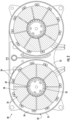
FIG. 1 is a perspective view of an inductor assembly according to an embodiment; -
FIG. 2 is a cross-sectional view of the inductor assembly ofFIG. 1 taken through a central plane according to an embodiment; -
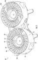
FIG. 3 is a perspective view of another inductor assembly according to an embodiment; -
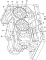
FIG. 4 is a perspective view of an inductor assembly mounted to a generator housing according to an embodiment; -
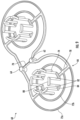
FIG. 5 is a perspective view of a back surface of a housing of an inductor assembly according to an embodiment; -
FIG. 6 is a detailed view of the identified portion ofFIG. 5 according to an embodiment; -
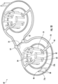
FIG. 7 is a perspective view of the coolant flow path formed in the inductor housing according to an embodiment; -
FIG. 8 is a perspective view of the coolant flow path formed in the inductor housing according to another embodiment; -
FIG. 9 is a perspective view of the coolant flow path formed in the inductor housing according to another embodiment; and -
FIG. 10 is a perspective view of the coolant flow path formed in the inductor housing according to another embodiment. - A detailed description of one or more embodiments of the disclosed apparatus and method are presented herein by way of exemplification and not limitation with reference to the Figures.
- With reference to
FIGS. 1-3 , an example of aninductor assembly 20 is shown. Theinductor assembly 20 includes ahousing 22 having abase 23 and anintegral sidewall 25 extending, such as perpendicularly for example, from thebase 23. Thebase 23 andsidewall 25 of thehousing 22 cooperate to define acavity 24 of thehousing 22 within which acore assembly 26 is received. Thecore assembly 26 includes acore 28 and a plurality ofwindings 30 wrapped about thecore 28. Eachcore 28 includes acentral opening 32 and aninsert 34 of thehousing 22 seats within thecentral opening 32 to restrict movement of thecore 28 relative to thehousing 22. Theinsert 34 is in thermal communication with thecore 28 and thewindings 30 wrapped about thecore 28. In an embodiment, the remaining inner volume of thecavity 24 is filled with a thermally conductive potting material. This potting material facilitates conduction of heat from thecore assembly 26, such as to thebase 23 and theinsert 34 of thehousing 22 for example. In an embodiment, acover 36 is disposed within thecavity 24 in overlapping arrangement with thecore assembly 26. As shown, thecover 36 includes a plurality ofopenings 38 through which a portion of the heat generated by thecore assembly 26 is dissipated. - In the non-limiting embodiment of
FIG. 1 , groups ofwindings 30 are spaced about the outer periphery of thecore 28. Another example of a configuration of thewindings 30 is shown inFIG. 3 . In the embodiment,individual windings 30 are equidistantly spaced about thecore 28. However, it should be understood that any suitable configuration of thewindings 30 is contemplated herein. In each of the embodiments, the, the heat flux at the inner diameter of thecore 28 is greater than at the outer diameter of thecore 28. - In an embodiment, the
housing 22 may be designed to support a plurality ofcore assemblies 26. For example, in the illustrated, non-limiting embodiments, theinductor assembly 20 includes afirst core assembly 26a arranged within afirst cavity 24a and asecond core 26b assembly arranged within asecond cavity 24b. The first andsecond core assembly core assemblies - With reference now to
FIG. 4 , theinductor assembly 20 is shown mounted adjacent anexterior surface 42 of agenerator housing 40. In such embodiments, thegenerator housing 40 may be mounted to a portion of a gas turbine engine of an aircraft, such as an accessories mounting and drive assemblies (AMAD) for example. As shown, a plurality ofconnector flanges 44 extend outwardly from various locations about a periphery of thehousing 22. In the illustrated, non-limiting embodiment, theconnector flanges 44 are arranged centrally between thefirst end 46 of thehousing 22 and a second,opposite end 48 of thehousing 22. Thefirst end 46 faces toward thegenerator housing 40, and thesecond end 48 faces outward from thegenerator housing 40. When theinductor housing 22 is positioned relative to thegenerator housing 40, each of the plurality ofconnector flanges 44 is aligned with and affixed to a correspondingstandoff 50 extending from thegenerator housing 40. An axial length of each of thestandoffs 50 is greater than the distance between thefirst end 46 of theinductor housing 22 and aconnector flange 44 such that when theinductor assembly 20 is mounted to thegenerator housing 40, thefirst end 46 of theinductor assembly 20 is offset therefrom. As a result, thermal coupling between theinductor assembly 20 and thegenerator housing 40 is limited to the interface between theconnector flanges 44 andstandoffs 50. - A flow of coolant, such as oil or glycol water for example, is used to cool the one or
more core assemblies 26 of theinductor assembly 20. - With reference now to
FIGS. 5-10 , aflow path 60 through which coolant flows to remove heat from thecore assembly 26 of theinductor assembly 20 is formed in thehousing 22. In an embodiment, theflow path 60 is machined into theinductor housing 22. In another embodiment, theflow path 60 may be formed simultaneously with thehousing 22, such as via an additive manufacturing process for example. A cover (not shown) is affixed to thebase 23 of theinductor housing 22, such as via brazing for example, to restrict the flow of coolant to within theflow path 60. - The
flow path 60 formed in thehousing 22 includes aninlet 62 and anoutlet 64 disposed adjacent opposite sides of thehousing 22. In embodiments where thehousing 22 includes afirst cavity 24a and asecond cavity 24b, and is therefore configured to receive afirst core assembly 26a and asecond core assembly 26b, theinlet 62 andoutlet 64 may be positioned centrally between the sidewalls 25 associated with the first andsecond core assemblies flow path 60 may include afirst flow path 66 for cooling thefirst core assembly 26a and asecond flow path 68 for cooling thesecond core assembly 26b. However, it should be understood that embodiments including a single flow path for cooling multiple core assemblies are also within the scope of the disclosure. In an embodiment, the first andsecond flow paths inlet 62 and theoutlet 64. Theflow path 60 may additionally include abypass flow path 70 directly coupling theinlet 62 and theoutlet 64 and arranged at the central portion of thehousing 22, between thecore assemblies - For ease of understanding, only the
first flow path 66 of each of the various coolant flow path configurations illustrated herein will be described. Each configuration of thefirst flow path 66 includes at least one first channel formed in the surface of the base 23 defining thefirst end 46 of thehousing 22. Thefirst flow path 66 additionally includes at least onesecond channel 74 formed over the height of theinsert 34. As a result, the coolant provided tofirst flow path 66 of thehousing 22 cools not only the portion of thehousing 22 adjacent a first end surface (not shown) of thecore assembly 26, but also cools theinsert 34 arranged in thermal communication with the inner diameter of thecore assembly 26. - Heat is configured to conduct from the
core assembly 26, through a potting material, to theflow path 60 formed in thehousing 22. In operation, a coolant is provided from theinlet 62 to thefirst flow path 66. As the coolant moves through thefirst flow path 66, the coolant not only absorbs heat conducted to thehousing 22 from theadjacent core assembly 26, but also absorbs heat via convection between thehousing 22 and the coolant. The heated coolant is then provided to theoutlet 64 where the heat may be removed from the coolant by a liquid or air cooled heat exchanger before returning the coolant to theinlet 62. - In the non-limiting embodiment illustrated in
FIGS. 5-7 , thefirst flow path 66 includes at least onefirst channel 72 having a non-linear configuration. As shown, the at least onefirst channel 72 includes a serpentine configuration extending between an interior portion of thebase 23, arranged generally adjacent theinsert 34 and an inner diameter of thefirst core assembly 26a, and outer portion of thebase 23, located generally adjacent the outer diameter of thefirst core assembly 26. The configuration of the at least onefirst channel 72 may align with each of the plurality ofwindings 30 of thecore assembly 26a. - The
first flow path 66 additionally includes at least one second channel 74 (best shown inFIG. 7 ) in fluid communication with thefirst channel 72. In the illustrated, non-limiting embodiment, thefirst flow path 66 includes a plurality ofsecond channels 74, separated from one another and spaced about the periphery of theinsert 34. The plurality ofsecond channels 74 extend through theinsert 34 of thehousing 22, for example, in a direction generally perpendicular to thebase 23 and thefirst channel 72. In the illustrated, non-limiting embodiment, thesecond channels 74 have a generally triangular configuration such that the portion of eachsecond channel 74 positioned furthest from thebase 23 includes an apex 76. Because the heat flux of thefirst core assembly 26a is greatest adjacent the inner diameter thereof, inclusion of thesesecond channels 74, which extend through theinsert 34 over at least a portion of the height of thefirst core assembly 26a, substantially cools the inner diameter of thefirst core assembly 26a. - According to the invention, the
first flow path 66 is divided into two parallel and substantially identical and/or symmetrical portions such that each portion removes heat from a corresponding portion of thefirst core assembly 26a. Accordingly, as shown, each of these portions of thefirst flow path 66 includes both first andsecond channels - With reference now to
FIGS. 8-10 , in another embodiment, thefirst flow path 66 includes a plurality of concentricfirst channels 72 arranged in fluid communication. In the illustrated, non-limiting embodiment, thefirst channels 72 are generally arcuate in shape such that afirst channel 72a is generally defined by a first radius, and anotherfirst channel 72b is generally defined by a second radius. The second radius is smaller than the first radius. In an embodiment, the radius of thefirst channel 72a is generally equal to an outer radius of acore assembly 26. - The
first flow path 66 additionally includes at least onesecond channel 74 arranged generally concentrically with thefirst channels 72. The at least onesecond channel 74 has a third radius, smaller than the second radius. According to the invention, the radius of at least one thesecond channel 74 is generally equal to a radius of theinsert 34, such that thesecond channel 74 is formed within theinsert 34. In an embodiment, thefirst channel 72a, anotherfirst channel 72b, andsecond channel 74 are arranged in parallel with respect to the flow of coolant, via anaxially extending connector 78. - As previously described, in each of the embodiments illustrated in
FIGS. 8-10 , thesecond channel 74 is formed in a portion of theinsert 34. Thesecond channel 74 is configured to extend both peripherally and vertically through theinsert 34. Accordingly, as shown, flow of coolant within thesecond channel 74 of thefirst flow path 66 is configured to repeatedly move between a first plane, aligned with thebase 23, and a second parallel plane offset from the first plane. In an embodiment, the second plane is defined by anupper surface 80 of theinsert 34, or alternatively, at any location between theupper surface 80 of theinsert 34 and thebase 23. - In the illustrated, non-limiting embodiment of
FIG. 8 , the portion of thefirst flow path 66 defined by thesecond channel 74 includes a plurality of angular sections arranged in series. Similar to the embodiment ofFIG. 7 , each angular section is triangular in shape and includes an apex 76 disposed at the furthest portion of thesecond channel 74 relative to thebase 23. In another embodiment, illustrated inFIG. 9 , the portion of thefirst flow path 66 defined by thesecond channel 74 is configured to move arcuately within both the first plane and the second plane. As shown, aplanar section 84 extends between adjacent parallel,vertical sections 82 of thesecond channel 74. The location of eachplanar section 84 varies sequentially between the first plane defined by thebase 23 and the second plane, such as defined by theupper surface 80 of theinsert 34 for example. - In an embodiment, best shown in
FIG. 10 , one of thefirst channels 72 of theflow path 66, such aschannel 72a for example, is configured to extend both peripherally and vertically through thesidewall 25 of thehousing 22. For example, the portion of thefirst flow path 66 defined by thefirst channel 72 may be configured to move arcuately within both the first plane defined by thebase 23 and a second, parallel plane. In an embodiment, the second parallel plane may be located at any position over the height of thesidewall 25. As shown inFIG. 10 , aplanar section 86 extends between adjacentvertical sections 88 formed in thefirst channel 72. Although thefirst channel 72 is shown as having a specific configuration, it should be understood that embodiments having any flow configuration extending both peripherally and vertically through thesidewall 25 are within the scope of the disclosure. - The overall configuration of the
flow path 60 may be customized to maximize the heat transfer between the coolant and the hot spots of thecore assembly 26, thereby reducing the temperature of thecore 28 andwindings 30 to below their respective material ratings. Further, by integrating the coolant flow into thehousing 22 of theinductor assembly 20, the need for additional components, and therefore the overall size of theassembly 20 may be reduced. Each of the non-limiting embodiments illustrated herein includes a plurality of narrow flow channels to ensure the light weight of thehousing 22 andinductor assembly 20, as well as a reduced pressure drop in theinductor assembly 20, which is critical for aerospace applications. - The term "about" is intended to include the degree of error associated with measurement of the particular quantity based upon the equipment available at the time of filing the application.
- The terminology used herein is for the purpose of describing particular embodiments only and is not intended to be limiting of the present disclosure. As used herein, the singular forms "a", "an" and "the" are intended to include the plural forms as well, unless the context clearly indicates otherwise. It will be further understood that the terms "comprises" and/or "comprising," when used in this specification, specify the presence of stated features, integers, steps, operations, elements, and/or components, but do not preclude the presence or addition of one or more other features, integers, steps, operations, element components, and/or groups thereof.
- While the present disclosure has been described with reference to an exemplary embodiment or embodiments, it will be understood by those skilled in the art that various changes may be made and equivalents may be substituted for elements thereof without departing from the scope of the present disclosure. In addition, many modifications may be made to adapt a particular situation or material to the teachings of the present disclosure without departing from the essential scope thereof. Therefore, it is intended that the present disclosure not be limited to the particular embodiment disclosed as the best mode contemplated for carrying out this present disclosure, but that the present disclosure will include all embodiments falling within the scope of the claims.
Claims (14)
- An inductor assembly (20) comprising:a housing (22) including a base (23), a sidewall (25), and an insert (34), wherein the base (23) and the sidewall define a cavity (24),a core assembly within the cavity (24), wherein the core assembly includes a core having a central opening (32) and a plurality of windings wrapped about the core and disposed between the sidewall and the insert; the insert (34) being positioned within the cavity (24) and seated within said central opening (32);anda flow path (60) formed in the housing for receiving a coolant to remove heat from the core assembly andwherein the flow path (60) has an inlet and an outlet formed at the base of the housing (22), and wherein the flow path (60) is divided into two parallel and substantially identical portions, each including at least one first channel (72) extending within a plane defined by the base (23) and at least one second channel (74) formed in the insert (34);wherein the at least one second channel (74) is in fluid communication with the at least one first channel (72); characterised in that the at least one first channel (72) includes a serpentine configuration extending between an interior potion of the base (23), arranged generally adjacent the insert (34) and an inner diameter of the core assembly, and an outer portion of the base (23), arranged generally adjacent the outer diameter of the core assembly.
- An inductor assembly (20) comprising:a housing (22) including a base (23), a sidewall (25), and an insert (34), wherein the base (23) and the sidewall define a cavity (24),a core assembly within the cavity (24), wherein the core assembly includes a core having a central opening (32) and a plurality of windings wrapped about the core and disposed between the sidewall and the insert; the insert (34) being positioned within the cavity (24) and seated within said central opening (32);anda flow path (60) formed in the housing for receiving a coolant to remove heat from the core assembly andwherein the flow path (60) has an inlet and an outlet formed at the base of the housing (22), and wherein the flow path (60) is divided into two parallel and substantially identical portions, each including at least one first channel (72) extending within a plane defined by the base (23) and at least one second channel (74) formed in the insert (34);wherein the at least one second channel (74) is in fluid communication with the at least one first channel (72); characterised in that the at least one first channel (72) includes a plurality of concentric first channels (72) arranged in fluid communication.
- The inductor assembly of claim 2, wherein the at least one first channel (72) has an arcuate contour.
- The inductor assembly of claim 3, wherein a radius of the first channel at least is equal to an outer diameter of the core.
- The inductor assembly of claim 2, wherein the first channel (72) comprises a portion that extends at an angle to the base, and preferably wherein the portion of the at least one first channel (72) is formed in the sidewall.
- The inductor assembly of claim 1 or 2, wherein a portion of the at least one second channel (74) extends at an angle into the base (23).
- The inductor assembly of claim 6 in dependence on claim 2, wherein the at least one second channel (74) includes a plurality of vertical sections extending in a direction perpendicular to the base fluidly coupled by a plurality of planar sections extending within a second plane parallel to the base.
- The inductor assembly of claim 5, wherein the at least one second channel (74) includes a triangular section having an apex opposite the base (23), and wherein the at least one second channel (74) includes a plurality of triangular sections arranged in series.
- The inductor assembly of any preceding claim, further comprising a base cover affixed to the base (23) of the housing.
- The inductor assembly of any preceding claim, wherein the housing of the inductor assembly further comprises another sidewall and another insert, the base (23) and the another sidewall defining another cavity, the another insert being positioned within the another cavity, another core assembly being received within the another cavity.
- The inductor assembly of claim 10, further comprising a second flow path for removing heat from the core positioned within the another cavity.
- The inductor assembly of claim 11, wherein the second flow path (68) is arranged in fluid communication with the inlet and the outlet.
- The inductor assembly of claim 11, wherein the flow path (66) and the second flow path (68) are symmetrical about an axis A, extending between the inlet (62) and the outlet (64).
- The inductor assembly of claim 11, further including a bypass flow path arranged in parallel with the flow path (66) and the second flow path (68).
Applications Claiming Priority (1)
| Application Number | Priority Date | Filing Date | Title |
|---|---|---|---|
| US16/176,600 US11348717B2 (en) | 2018-10-31 | 2018-10-31 | Thermal management of high power inductors |
Publications (2)
| Publication Number | Publication Date |
|---|---|
| EP3648125A1 EP3648125A1 (en) | 2020-05-06 |
| EP3648125B1 true EP3648125B1 (en) | 2024-07-10 |
Family
ID=68392822
Family Applications (1)
| Application Number | Title | Priority Date | Filing Date |
|---|---|---|---|
| EP19206039.0A Active EP3648125B1 (en) | 2018-10-31 | 2019-10-29 | Thermal management of high power inductors |
Country Status (3)
| Country | Link |
|---|---|
| US (1) | US11348717B2 (en) |
| EP (1) | EP3648125B1 (en) |
| KR (1) | KR102762836B1 (en) |
Families Citing this family (4)
| Publication number | Priority date | Publication date | Assignee | Title |
|---|---|---|---|---|
| US20210398731A1 (en) * | 2020-06-23 | 2021-12-23 | Hamilton Sundstrand Corporation | Thermal management of toroidal transformer on a cold plate |
| US11557419B2 (en) | 2020-06-23 | 2023-01-17 | Hamilton Sundstrand Corporation | Thermal management of inductor on a cold plate |
| US12040118B2 (en) * | 2020-11-30 | 2024-07-16 | Hamilton Sundstrand Corporation | Cooling system for a transformer and a method of cooling a transformer |
| US20230403817A1 (en) | 2022-05-17 | 2023-12-14 | Hamilton Sundstrand Corporation | Fluid-cooled electrical component |
Family Cites Families (10)
| Publication number | Priority date | Publication date | Assignee | Title |
|---|---|---|---|---|
| US7002443B2 (en) | 2003-06-25 | 2006-02-21 | Cymer, Inc. | Method and apparatus for cooling magnetic circuit elements |
| US8125777B1 (en) | 2008-07-03 | 2012-02-28 | Ctm Magnetics, Inc. | Methods and apparatus for electrical components |
| US8570132B2 (en) * | 2009-10-27 | 2013-10-29 | GM Global Technology Operations LLC | Power electronics assembly with multi-sided inductor cooling |
| EP2797090A1 (en) | 2013-04-25 | 2014-10-29 | Magnetic Components Sweden AB | Thermal management system for SMC inductors |
| US9299488B2 (en) | 2013-10-04 | 2016-03-29 | Hamilton Sundstrand Corporation | Magnetic devices with integral cooling channels |
| DE102015203286A1 (en) | 2014-02-28 | 2015-09-03 | Ford Global Technologies, Llc | LIQUID-COOLED POWER INDUCTOR |
| US9373436B2 (en) | 2014-07-07 | 2016-06-21 | Hamilton Sundstrand Corporation | Liquid cooled inductors |
| US20160005524A1 (en) | 2014-07-07 | 2016-01-07 | Hamilton Sundstrand Corporation | Immersion cooled toroid inductor assembly |
| US10573458B2 (en) | 2016-10-05 | 2020-02-25 | The Boeing Company | Superconducting air core inductor systems and methods |
| US10141095B2 (en) | 2016-11-04 | 2018-11-27 | Ford Global Technologies, Llc | Inductor cooling systems and methods |
-
2018
- 2018-10-31 US US16/176,600 patent/US11348717B2/en active Active
-
2019
- 2019-10-22 KR KR1020190131246A patent/KR102762836B1/en active Active
- 2019-10-29 EP EP19206039.0A patent/EP3648125B1/en active Active
Also Published As
| Publication number | Publication date |
|---|---|
| KR102762836B1 (en) | 2025-02-05 |
| KR20200049561A (en) | 2020-05-08 |
| US11348717B2 (en) | 2022-05-31 |
| EP3648125A1 (en) | 2020-05-06 |
| US20200135378A1 (en) | 2020-04-30 |
Similar Documents
| Publication | Publication Date | Title |
|---|---|---|
| EP3648125A1 (en) | Thermal management of high power inductors | |
| EP2966659B1 (en) | Liquid cooled inductors | |
| JP5908975B2 (en) | Cartridge-based thermoelectric system | |
| EP2502242B1 (en) | Electrical transformer with diaphragm and method of cooling same | |
| JP6799014B2 (en) | High thermal conductivity wafer support pedestal device | |
| EP2711941B1 (en) | Electrical inductor assembly and method of cooling an electrical inductor assembly | |
| EP2369723A2 (en) | Cooling arrangement for an electric machine | |
| US20160352201A1 (en) | Integrated heat dissipative structure for electric machine | |
| EP3499524B1 (en) | System for housing and cooling a toroidal inductor | |
| US11374445B2 (en) | Stator unit of rotary electric machine | |
| US20220045568A1 (en) | Method and apparatus for motor cooling | |
| EP3731246A1 (en) | Self-contained cooling device for an electromagnetic interference filter | |
| EP3654500A1 (en) | Apparatus and method for cooling endwindings in a rotating electric machine | |
| EP3193127A1 (en) | Thermal stress relief for heat sinks | |
| EP3929950A1 (en) | Thermal management of inductor on a cold plate | |
| US10615663B2 (en) | Electrical motor cooling design | |
| US3254246A (en) | Dynamoelectric machines | |
| WO2019084379A1 (en) | Cooled lubricant filter housing | |
| EP3929949B1 (en) | Thermal management of toroidal transformer on a cold plate | |
| EP2568484B1 (en) | Electro-magnetic device having a polymer housing | |
| EP3131182B1 (en) | Cooling of the coil turn in a rotor assembly | |
| CN106849510B (en) | System for cooling motor stator | |
| US12160161B1 (en) | Immersion-cooled axial flux electric motors and methods of operating thereof | |
| WO2022173421A1 (en) | Cooling channels in a high-density motor | |
| EP4006925B1 (en) | Cooling system for a transformer and a method of cooling a transformer |
Legal Events
| Date | Code | Title | Description |
|---|---|---|---|
| PUAI | Public reference made under article 153(3) epc to a published international application that has entered the european phase |
Free format text: ORIGINAL CODE: 0009012 |
|
| STAA | Information on the status of an ep patent application or granted ep patent |
Free format text: STATUS: THE APPLICATION HAS BEEN PUBLISHED |
|
| AK | Designated contracting states |
Kind code of ref document: A1 Designated state(s): AL AT BE BG CH CY CZ DE DK EE ES FI FR GB GR HR HU IE IS IT LI LT LU LV MC MK MT NL NO PL PT RO RS SE SI SK SM TR |
|
| AX | Request for extension of the european patent |
Extension state: BA ME |
|
| STAA | Information on the status of an ep patent application or granted ep patent |
Free format text: STATUS: REQUEST FOR EXAMINATION WAS MADE |
|
| 17P | Request for examination filed |
Effective date: 20201103 |
|
| RBV | Designated contracting states (corrected) |
Designated state(s): AL AT BE BG CH CY CZ DE DK EE ES FI FR GB GR HR HU IE IS IT LI LT LU LV MC MK MT NL NO PL PT RO RS SE SI SK SM TR |
|
| STAA | Information on the status of an ep patent application or granted ep patent |
Free format text: STATUS: EXAMINATION IS IN PROGRESS |
|
| 17Q | First examination report despatched |
Effective date: 20210323 |
|
| GRAP | Despatch of communication of intention to grant a patent |
Free format text: ORIGINAL CODE: EPIDOSNIGR1 |
|
| STAA | Information on the status of an ep patent application or granted ep patent |
Free format text: STATUS: GRANT OF PATENT IS INTENDED |
|
| INTG | Intention to grant announced |
Effective date: 20240219 |
|
| RIN1 | Information on inventor provided before grant (corrected) |
Inventor name: SHEPARD, CHARLES Inventor name: DOWNING, RICHARD L. Inventor name: METZLER, MARK W. Inventor name: PAL, DEBABRATA Inventor name: JOSHI, ASHUTOSH |
|
| GRAS | Grant fee paid |
Free format text: ORIGINAL CODE: EPIDOSNIGR3 |
|
| GRAA | (expected) grant |
Free format text: ORIGINAL CODE: 0009210 |
|
| STAA | Information on the status of an ep patent application or granted ep patent |
Free format text: STATUS: THE PATENT HAS BEEN GRANTED |
|
| AK | Designated contracting states |
Kind code of ref document: B1 Designated state(s): AL AT BE BG CH CY CZ DE DK EE ES FI FR GB GR HR HU IE IS IT LI LT LU LV MC MK MT NL NO PL PT RO RS SE SI SK SM TR |
|
| REG | Reference to a national code |
Ref country code: CH Ref legal event code: EP |
|
| REG | Reference to a national code |
Ref country code: DE Ref legal event code: R096 Ref document number: 602019054899 Country of ref document: DE |
|
| REG | Reference to a national code |
Ref country code: LT Ref legal event code: MG9D |
|
| REG | Reference to a national code |
Ref country code: NL Ref legal event code: MP Effective date: 20240710 |
|
| PG25 | Lapsed in a contracting state [announced via postgrant information from national office to epo] |
Ref country code: PT Free format text: LAPSE BECAUSE OF FAILURE TO SUBMIT A TRANSLATION OF THE DESCRIPTION OR TO PAY THE FEE WITHIN THE PRESCRIBED TIME-LIMIT Effective date: 20241111 |
|
| REG | Reference to a national code |
Ref country code: AT Ref legal event code: MK05 Ref document number: 1702793 Country of ref document: AT Kind code of ref document: T Effective date: 20240710 |
|
| PG25 | Lapsed in a contracting state [announced via postgrant information from national office to epo] |
Ref country code: NL Free format text: LAPSE BECAUSE OF FAILURE TO SUBMIT A TRANSLATION OF THE DESCRIPTION OR TO PAY THE FEE WITHIN THE PRESCRIBED TIME-LIMIT Effective date: 20240710 |
|
| PG25 | Lapsed in a contracting state [announced via postgrant information from national office to epo] |
Ref country code: PT Free format text: LAPSE BECAUSE OF FAILURE TO SUBMIT A TRANSLATION OF THE DESCRIPTION OR TO PAY THE FEE WITHIN THE PRESCRIBED TIME-LIMIT Effective date: 20241111 Ref country code: NL Free format text: LAPSE BECAUSE OF FAILURE TO SUBMIT A TRANSLATION OF THE DESCRIPTION OR TO PAY THE FEE WITHIN THE PRESCRIBED TIME-LIMIT Effective date: 20240710 |
|
| PG25 | Lapsed in a contracting state [announced via postgrant information from national office to epo] |
Ref country code: NO Free format text: LAPSE BECAUSE OF FAILURE TO SUBMIT A TRANSLATION OF THE DESCRIPTION OR TO PAY THE FEE WITHIN THE PRESCRIBED TIME-LIMIT Effective date: 20241010 |
|
| PG25 | Lapsed in a contracting state [announced via postgrant information from national office to epo] |
Ref country code: GR Free format text: LAPSE BECAUSE OF FAILURE TO SUBMIT A TRANSLATION OF THE DESCRIPTION OR TO PAY THE FEE WITHIN THE PRESCRIBED TIME-LIMIT Effective date: 20241011 Ref country code: FI Free format text: LAPSE BECAUSE OF FAILURE TO SUBMIT A TRANSLATION OF THE DESCRIPTION OR TO PAY THE FEE WITHIN THE PRESCRIBED TIME-LIMIT Effective date: 20240710 Ref country code: PL Free format text: LAPSE BECAUSE OF FAILURE TO SUBMIT A TRANSLATION OF THE DESCRIPTION OR TO PAY THE FEE WITHIN THE PRESCRIBED TIME-LIMIT Effective date: 20240710 |
|
| PG25 | Lapsed in a contracting state [announced via postgrant information from national office to epo] |
Ref country code: BG Free format text: LAPSE BECAUSE OF FAILURE TO SUBMIT A TRANSLATION OF THE DESCRIPTION OR TO PAY THE FEE WITHIN THE PRESCRIBED TIME-LIMIT Effective date: 20240710 |
|
| PG25 | Lapsed in a contracting state [announced via postgrant information from national office to epo] |
Ref country code: LV Free format text: LAPSE BECAUSE OF FAILURE TO SUBMIT A TRANSLATION OF THE DESCRIPTION OR TO PAY THE FEE WITHIN THE PRESCRIBED TIME-LIMIT Effective date: 20240710 |
|
| PG25 | Lapsed in a contracting state [announced via postgrant information from national office to epo] |
Ref country code: AT Free format text: LAPSE BECAUSE OF FAILURE TO SUBMIT A TRANSLATION OF THE DESCRIPTION OR TO PAY THE FEE WITHIN THE PRESCRIBED TIME-LIMIT Effective date: 20240710 Ref country code: IS Free format text: LAPSE BECAUSE OF FAILURE TO SUBMIT A TRANSLATION OF THE DESCRIPTION OR TO PAY THE FEE WITHIN THE PRESCRIBED TIME-LIMIT Effective date: 20241110 |
|
| PG25 | Lapsed in a contracting state [announced via postgrant information from national office to epo] |
Ref country code: HR Free format text: LAPSE BECAUSE OF FAILURE TO SUBMIT A TRANSLATION OF THE DESCRIPTION OR TO PAY THE FEE WITHIN THE PRESCRIBED TIME-LIMIT Effective date: 20240710 |
|
| PG25 | Lapsed in a contracting state [announced via postgrant information from national office to epo] |
Ref country code: ES Free format text: LAPSE BECAUSE OF FAILURE TO SUBMIT A TRANSLATION OF THE DESCRIPTION OR TO PAY THE FEE WITHIN THE PRESCRIBED TIME-LIMIT Effective date: 20240710 Ref country code: RS Free format text: LAPSE BECAUSE OF FAILURE TO SUBMIT A TRANSLATION OF THE DESCRIPTION OR TO PAY THE FEE WITHIN THE PRESCRIBED TIME-LIMIT Effective date: 20241010 |
|
| PG25 | Lapsed in a contracting state [announced via postgrant information from national office to epo] |
Ref country code: RS Free format text: LAPSE BECAUSE OF FAILURE TO SUBMIT A TRANSLATION OF THE DESCRIPTION OR TO PAY THE FEE WITHIN THE PRESCRIBED TIME-LIMIT Effective date: 20241010 Ref country code: PL Free format text: LAPSE BECAUSE OF FAILURE TO SUBMIT A TRANSLATION OF THE DESCRIPTION OR TO PAY THE FEE WITHIN THE PRESCRIBED TIME-LIMIT Effective date: 20240710 Ref country code: NO Free format text: LAPSE BECAUSE OF FAILURE TO SUBMIT A TRANSLATION OF THE DESCRIPTION OR TO PAY THE FEE WITHIN THE PRESCRIBED TIME-LIMIT Effective date: 20241010 Ref country code: LV Free format text: LAPSE BECAUSE OF FAILURE TO SUBMIT A TRANSLATION OF THE DESCRIPTION OR TO PAY THE FEE WITHIN THE PRESCRIBED TIME-LIMIT Effective date: 20240710 Ref country code: IS Free format text: LAPSE BECAUSE OF FAILURE TO SUBMIT A TRANSLATION OF THE DESCRIPTION OR TO PAY THE FEE WITHIN THE PRESCRIBED TIME-LIMIT Effective date: 20241110 Ref country code: HR Free format text: LAPSE BECAUSE OF FAILURE TO SUBMIT A TRANSLATION OF THE DESCRIPTION OR TO PAY THE FEE WITHIN THE PRESCRIBED TIME-LIMIT Effective date: 20240710 Ref country code: GR Free format text: LAPSE BECAUSE OF FAILURE TO SUBMIT A TRANSLATION OF THE DESCRIPTION OR TO PAY THE FEE WITHIN THE PRESCRIBED TIME-LIMIT Effective date: 20241011 Ref country code: FI Free format text: LAPSE BECAUSE OF FAILURE TO SUBMIT A TRANSLATION OF THE DESCRIPTION OR TO PAY THE FEE WITHIN THE PRESCRIBED TIME-LIMIT Effective date: 20240710 Ref country code: ES Free format text: LAPSE BECAUSE OF FAILURE TO SUBMIT A TRANSLATION OF THE DESCRIPTION OR TO PAY THE FEE WITHIN THE PRESCRIBED TIME-LIMIT Effective date: 20240710 Ref country code: BG Free format text: LAPSE BECAUSE OF FAILURE TO SUBMIT A TRANSLATION OF THE DESCRIPTION OR TO PAY THE FEE WITHIN THE PRESCRIBED TIME-LIMIT Effective date: 20240710 Ref country code: AT Free format text: LAPSE BECAUSE OF FAILURE TO SUBMIT A TRANSLATION OF THE DESCRIPTION OR TO PAY THE FEE WITHIN THE PRESCRIBED TIME-LIMIT Effective date: 20240710 |
|
| REG | Reference to a national code |
Ref country code: DE Ref legal event code: R097 Ref document number: 602019054899 Country of ref document: DE |
|
| PG25 | Lapsed in a contracting state [announced via postgrant information from national office to epo] |
Ref country code: SM Free format text: LAPSE BECAUSE OF FAILURE TO SUBMIT A TRANSLATION OF THE DESCRIPTION OR TO PAY THE FEE WITHIN THE PRESCRIBED TIME-LIMIT Effective date: 20240710 Ref country code: DK Free format text: LAPSE BECAUSE OF FAILURE TO SUBMIT A TRANSLATION OF THE DESCRIPTION OR TO PAY THE FEE WITHIN THE PRESCRIBED TIME-LIMIT Effective date: 20240710 Ref country code: RO Free format text: LAPSE BECAUSE OF FAILURE TO SUBMIT A TRANSLATION OF THE DESCRIPTION OR TO PAY THE FEE WITHIN THE PRESCRIBED TIME-LIMIT Effective date: 20240710 |
|
| PG25 | Lapsed in a contracting state [announced via postgrant information from national office to epo] |
Ref country code: EE Free format text: LAPSE BECAUSE OF FAILURE TO SUBMIT A TRANSLATION OF THE DESCRIPTION OR TO PAY THE FEE WITHIN THE PRESCRIBED TIME-LIMIT Effective date: 20240710 |
|
| PG25 | Lapsed in a contracting state [announced via postgrant information from national office to epo] |
Ref country code: CZ Free format text: LAPSE BECAUSE OF FAILURE TO SUBMIT A TRANSLATION OF THE DESCRIPTION OR TO PAY THE FEE WITHIN THE PRESCRIBED TIME-LIMIT Effective date: 20240710 |
|
| PG25 | Lapsed in a contracting state [announced via postgrant information from national office to epo] |
Ref country code: IT Free format text: LAPSE BECAUSE OF FAILURE TO SUBMIT A TRANSLATION OF THE DESCRIPTION OR TO PAY THE FEE WITHIN THE PRESCRIBED TIME-LIMIT Effective date: 20240710 Ref country code: SK Free format text: LAPSE BECAUSE OF FAILURE TO SUBMIT A TRANSLATION OF THE DESCRIPTION OR TO PAY THE FEE WITHIN THE PRESCRIBED TIME-LIMIT Effective date: 20240710 |
|
| PLBE | No opposition filed within time limit |
Free format text: ORIGINAL CODE: 0009261 |
|
| STAA | Information on the status of an ep patent application or granted ep patent |
Free format text: STATUS: NO OPPOSITION FILED WITHIN TIME LIMIT |
|
| REG | Reference to a national code |
Ref country code: CH Ref legal event code: PL |
|
| 26N | No opposition filed |
Effective date: 20250411 |
|
| PG25 | Lapsed in a contracting state [announced via postgrant information from national office to epo] |
Ref country code: MC Free format text: LAPSE BECAUSE OF FAILURE TO SUBMIT A TRANSLATION OF THE DESCRIPTION OR TO PAY THE FEE WITHIN THE PRESCRIBED TIME-LIMIT Effective date: 20240710 |
|
| PG25 | Lapsed in a contracting state [announced via postgrant information from national office to epo] |
Ref country code: LU Free format text: LAPSE BECAUSE OF NON-PAYMENT OF DUE FEES Effective date: 20241029 Ref country code: BE Free format text: LAPSE BECAUSE OF NON-PAYMENT OF DUE FEES Effective date: 20241031 |
|
| PG25 | Lapsed in a contracting state [announced via postgrant information from national office to epo] |
Ref country code: CH Free format text: LAPSE BECAUSE OF NON-PAYMENT OF DUE FEES Effective date: 20241031 |
|
| REG | Reference to a national code |
Ref country code: BE Ref legal event code: MM Effective date: 20241031 |
|
| PG25 | Lapsed in a contracting state [announced via postgrant information from national office to epo] |
Ref country code: SE Free format text: LAPSE BECAUSE OF FAILURE TO SUBMIT A TRANSLATION OF THE DESCRIPTION OR TO PAY THE FEE WITHIN THE PRESCRIBED TIME-LIMIT Effective date: 20240710 |
|
| PGFP | Annual fee paid to national office [announced via postgrant information from national office to epo] |
Ref country code: GB Payment date: 20250923 Year of fee payment: 7 |
|
| PGFP | Annual fee paid to national office [announced via postgrant information from national office to epo] |
Ref country code: FR Payment date: 20250924 Year of fee payment: 7 |
|
| PG25 | Lapsed in a contracting state [announced via postgrant information from national office to epo] |
Ref country code: IE Free format text: LAPSE BECAUSE OF NON-PAYMENT OF DUE FEES Effective date: 20241029 |
|
| PGFP | Annual fee paid to national office [announced via postgrant information from national office to epo] |
Ref country code: DE Payment date: 20250923 Year of fee payment: 7 |
|
| PG25 | Lapsed in a contracting state [announced via postgrant information from national office to epo] |
Ref country code: HU Free format text: LAPSE BECAUSE OF FAILURE TO SUBMIT A TRANSLATION OF THE DESCRIPTION OR TO PAY THE FEE WITHIN THE PRESCRIBED TIME-LIMIT; INVALID AB INITIO Effective date: 20191029 |
|
| PG25 | Lapsed in a contracting state [announced via postgrant information from national office to epo] |
Ref country code: CY Free format text: LAPSE BECAUSE OF FAILURE TO SUBMIT A TRANSLATION OF THE DESCRIPTION OR TO PAY THE FEE WITHIN THE PRESCRIBED TIME-LIMIT; INVALID AB INITIO Effective date: 20191029 |