EP3648063A1 - Image display apparatus, radiation imaging display system, image display method, and image display program - Google Patents
Image display apparatus, radiation imaging display system, image display method, and image display program Download PDFInfo
- Publication number
- EP3648063A1 EP3648063A1 EP19205403.9A EP19205403A EP3648063A1 EP 3648063 A1 EP3648063 A1 EP 3648063A1 EP 19205403 A EP19205403 A EP 19205403A EP 3648063 A1 EP3648063 A1 EP 3648063A1
- Authority
- EP
- European Patent Office
- Prior art keywords
- image
- depth
- radiation image
- dimensional radiation
- tomographic
- Prior art date
- Legal status (The legal status is an assumption and is not a legal conclusion. Google has not performed a legal analysis and makes no representation as to the accuracy of the status listed.)
- Granted
Links
Images



Classifications
-
- G—PHYSICS
- G06—COMPUTING OR CALCULATING; COUNTING
- G06T—IMAGE DATA PROCESSING OR GENERATION, IN GENERAL
- G06T12/00—Tomographic reconstruction from projections
-
- A—HUMAN NECESSITIES
- A61—MEDICAL OR VETERINARY SCIENCE; HYGIENE
- A61B—DIAGNOSIS; SURGERY; IDENTIFICATION
- A61B6/00—Apparatus or devices for radiation diagnosis; Apparatus or devices for radiation diagnosis combined with radiation therapy equipment
- A61B6/46—Arrangements for interfacing with the operator or the patient
- A61B6/461—Displaying means of special interest
-
- A—HUMAN NECESSITIES
- A61—MEDICAL OR VETERINARY SCIENCE; HYGIENE
- A61B—DIAGNOSIS; SURGERY; IDENTIFICATION
- A61B6/00—Apparatus or devices for radiation diagnosis; Apparatus or devices for radiation diagnosis combined with radiation therapy equipment
- A61B6/02—Arrangements for diagnosis sequentially in different planes; Stereoscopic radiation diagnosis
- A61B6/025—Tomosynthesis
-
- A—HUMAN NECESSITIES
- A61—MEDICAL OR VETERINARY SCIENCE; HYGIENE
- A61B—DIAGNOSIS; SURGERY; IDENTIFICATION
- A61B6/00—Apparatus or devices for radiation diagnosis; Apparatus or devices for radiation diagnosis combined with radiation therapy equipment
- A61B6/46—Arrangements for interfacing with the operator or the patient
- A61B6/467—Arrangements for interfacing with the operator or the patient characterised by special input means
- A61B6/469—Arrangements for interfacing with the operator or the patient characterised by special input means for selecting a region of interest [ROI]
-
- A—HUMAN NECESSITIES
- A61—MEDICAL OR VETERINARY SCIENCE; HYGIENE
- A61B—DIAGNOSIS; SURGERY; IDENTIFICATION
- A61B6/00—Apparatus or devices for radiation diagnosis; Apparatus or devices for radiation diagnosis combined with radiation therapy equipment
- A61B6/50—Apparatus or devices for radiation diagnosis; Apparatus or devices for radiation diagnosis combined with radiation therapy equipment specially adapted for specific body parts; specially adapted for specific clinical applications
- A61B6/502—Apparatus or devices for radiation diagnosis; Apparatus or devices for radiation diagnosis combined with radiation therapy equipment specially adapted for specific body parts; specially adapted for specific clinical applications for diagnosis of breast, i.e. mammography
-
- A—HUMAN NECESSITIES
- A61—MEDICAL OR VETERINARY SCIENCE; HYGIENE
- A61B—DIAGNOSIS; SURGERY; IDENTIFICATION
- A61B6/00—Apparatus or devices for radiation diagnosis; Apparatus or devices for radiation diagnosis combined with radiation therapy equipment
- A61B6/52—Devices using data or image processing specially adapted for radiation diagnosis
- A61B6/5211—Devices using data or image processing specially adapted for radiation diagnosis involving processing of medical diagnostic data
- A61B6/5229—Devices using data or image processing specially adapted for radiation diagnosis involving processing of medical diagnostic data combining image data of a patient, e.g. combining a functional image with an anatomical image
- A61B6/5235—Devices using data or image processing specially adapted for radiation diagnosis involving processing of medical diagnostic data combining image data of a patient, e.g. combining a functional image with an anatomical image combining images from the same or different ionising radiation imaging techniques, e.g. PET and CT
-
- G—PHYSICS
- G06—COMPUTING OR CALCULATING; COUNTING
- G06T—IMAGE DATA PROCESSING OR GENERATION, IN GENERAL
- G06T12/00—Tomographic reconstruction from projections
- G06T12/30—Image post-processing, e.g. metal artefact correction
-
- G—PHYSICS
- G06—COMPUTING OR CALCULATING; COUNTING
- G06T—IMAGE DATA PROCESSING OR GENERATION, IN GENERAL
- G06T7/00—Image analysis
- G06T7/0002—Inspection of images, e.g. flaw detection
- G06T7/0012—Biomedical image inspection
-
- G—PHYSICS
- G06—COMPUTING OR CALCULATING; COUNTING
- G06T—IMAGE DATA PROCESSING OR GENERATION, IN GENERAL
- G06T7/00—Image analysis
- G06T7/30—Determination of transform parameters for the alignment of images, i.e. image registration
-
- G—PHYSICS
- G06—COMPUTING OR CALCULATING; COUNTING
- G06T—IMAGE DATA PROCESSING OR GENERATION, IN GENERAL
- G06T7/00—Image analysis
- G06T7/50—Depth or shape recovery
- G06T7/55—Depth or shape recovery from multiple images
-
- A—HUMAN NECESSITIES
- A61—MEDICAL OR VETERINARY SCIENCE; HYGIENE
- A61B—DIAGNOSIS; SURGERY; IDENTIFICATION
- A61B6/00—Apparatus or devices for radiation diagnosis; Apparatus or devices for radiation diagnosis combined with radiation therapy equipment
- A61B6/02—Arrangements for diagnosis sequentially in different planes; Stereoscopic radiation diagnosis
- A61B6/03—Computed tomography [CT]
- A61B6/032—Transmission computed tomography [CT]
-
- A—HUMAN NECESSITIES
- A61—MEDICAL OR VETERINARY SCIENCE; HYGIENE
- A61B—DIAGNOSIS; SURGERY; IDENTIFICATION
- A61B6/00—Apparatus or devices for radiation diagnosis; Apparatus or devices for radiation diagnosis combined with radiation therapy equipment
- A61B6/04—Positioning of patients; Tiltable beds or the like
- A61B6/0407—Supports, e.g. tables or beds, for the body or parts of the body
- A61B6/0414—Supports, e.g. tables or beds, for the body or parts of the body with compression means
-
- A—HUMAN NECESSITIES
- A61—MEDICAL OR VETERINARY SCIENCE; HYGIENE
- A61B—DIAGNOSIS; SURGERY; IDENTIFICATION
- A61B6/00—Apparatus or devices for radiation diagnosis; Apparatus or devices for radiation diagnosis combined with radiation therapy equipment
- A61B6/46—Arrangements for interfacing with the operator or the patient
- A61B6/461—Displaying means of special interest
- A61B6/466—Displaying means of special interest adapted to display 3D data
-
- G—PHYSICS
- G06—COMPUTING OR CALCULATING; COUNTING
- G06T—IMAGE DATA PROCESSING OR GENERATION, IN GENERAL
- G06T2207/00—Indexing scheme for image analysis or image enhancement
- G06T2207/10—Image acquisition modality
- G06T2207/10028—Range image; Depth image; 3D point clouds
-
- G—PHYSICS
- G06—COMPUTING OR CALCULATING; COUNTING
- G06T—IMAGE DATA PROCESSING OR GENERATION, IN GENERAL
- G06T2207/00—Indexing scheme for image analysis or image enhancement
- G06T2207/10—Image acquisition modality
- G06T2207/10072—Tomographic images
- G06T2207/10112—Digital tomosynthesis [DTS]
-
- G—PHYSICS
- G06—COMPUTING OR CALCULATING; COUNTING
- G06T—IMAGE DATA PROCESSING OR GENERATION, IN GENERAL
- G06T2207/00—Indexing scheme for image analysis or image enhancement
- G06T2207/10—Image acquisition modality
- G06T2207/10116—X-ray image
-
- G—PHYSICS
- G06—COMPUTING OR CALCULATING; COUNTING
- G06T—IMAGE DATA PROCESSING OR GENERATION, IN GENERAL
- G06T2207/00—Indexing scheme for image analysis or image enhancement
- G06T2207/30—Subject of image; Context of image processing
- G06T2207/30004—Biomedical image processing
- G06T2207/30068—Mammography; Breast
-
- G—PHYSICS
- G06—COMPUTING OR CALCULATING; COUNTING
- G06T—IMAGE DATA PROCESSING OR GENERATION, IN GENERAL
- G06T2211/00—Image generation
- G06T2211/40—Computed tomography
- G06T2211/436—Limited angle
Definitions
- the present disclosure relates to an image display apparatus, a radiation imaging display system, an image display method, and an image display program.
- a technique for performing cross reference between a two-dimensional radiation image acquired by plain radiography and tomographic images acquired through tomography using a computed tomography (CT) apparatus, a magnetic resonance imaging (MRI) apparatus, a tomosynthesis imaging apparatus, or the like has been used.
- a technique for confirming of the presence or absence of a lesion (tumor or calcification) in the breast by perform cross reference between two-dimensional radiation images acquired by performing plain radiography in a variety of imaging directions such as a craniocaudal (CC) imaging for performing imaging by irradiating radiation from an upper side, mediolateral (ML) imaging for performing imaging by irradiating radiation from a lateral side, a mediolateral oblique (MLO) imaging for performing imaging by irradiating radiation in an oblique direction, or the like, and tomographic images generated by reconstructing a plurality of radiation images acquired through tomosynthesis imaging in the variety of imaging directions has been used.
- CC craniocaudal
- ML mediolateral
- MLO mediolateral oblique
- the tomosynthesis imaging is a method for performing imaging by irradiating radiation to a subject in a plurality of different directions while moving a radiation source and reconstructing an image acquired in this way to obtain an image in which a desired cross-section is emphasized.
- a plurality of radiation images are acquired by imaging the subject at a plurality of irradiation positions having different irradiation angles by moving the radiation source in parallel with a radiation detector or moving the radiation source to draw an arc of a circle or an ellipse, and tomographic images are generated by reconstructing these radiation images using a back-projection method such as a simple back-projection method or a filtered back-projection method.
- a two-dimensional radiation image has merits in that perspicuity is excellent, sharpness is high, and it is easy to compare the two-dimensional radiation image with a previous image, as compared with a tomographic image. Accordingly, cross reference between the two-dimensional radiation image and the tomographic image is performed by performing image analysis by displaying the two-dimensional radiation image on a display device such as a liquid crystal monitor, designating a position where it is considered that a lesion is present on the two-dimensional radiation image through clicking or the like, and displaying the tomographic image obtained by enlarging a region in the vicinity of the lesion.
- cross reference is performed by simultaneously displaying a two-dimensional radiation image and tomographic images corresponding to an imaging direction of the two-dimensional radiation image.
- the tomographic image is automatically or manually displayed while switching tomographic planes.
- a plurality of tomographic images are acquired by the tomography imaging such as the above-mentioned tomosynthesis imaging, but since there are a tomographic image of a tomographic plane on which a lesion or the like is included and a tomographic image of a tomographic plane on which the lesion is not included, a user such as a doctor who performs image analysis needs to perform interpretation while switching the plurality of tomographic images. Accordingly, in a case where image diagnosis is performed by performing cross reference between two-dimensional radiation images and tomographic images, its operation is troublesome as compared with a case where only the two-dimensional radiation images are used, and consequently, it takes long time to perform diagnosis.
- an object of the invention is to provide an image display apparatus, a radiation imaging display system, an image display method, and an image display program capable of accurately displaying, in performing image diagnosis by performing cross reference between a two-dimensional radiation image and a tomographic image, a tomographic image corresponding to a designated position on the two-dimensional radiation image.
- an image display apparatus comprising: a depth map creating unit that creates, on the basis of a two-dimensional radiation image and a plurality of tomographic images for the same subject, a plurality of depth maps in which each position on the two-dimensional radiation image and depth information indicating a depth directional position of a tomographic plane corresponding to each position are associated with each other while changing a correspondence relationship between each position on the two-dimensional radiation image and the depth information.
- the depth map creating unit may create the plurality of depth maps for each frequency component of the two-dimensional radiation image and the plurality of tomographic images.
- the depth map creating unit may create the plurality of depth maps for each object in the two-dimensional radiation image and the plurality of tomographic images.
- the depth map creating unit may create the depth maps by associating each position on the two-dimensional radiation image and the depth information indicating the depth directional position of the tomographic plane corresponding to each position on the basis of a correlation between each position on the two-dimensional radiation image and the plurality of tomographic images.
- the depth map creating unit may divide the two-dimensional image into a plurality of regions, and may create the depth maps by associating a position of each region on the two-dimensional radiation image and the depth information indicating the depth directional position of the tomographic plane corresponding to the position of each region.
- the image display apparatus may further comprise a display control unit that specifies depth information on a reference position in the two-dimensional radiation image with reference to the depth maps and displays a tomographic image of a tomographic plane indicated by the specified depth information on a display unit.
- the image display apparatus may further comprise: an input unit that receives designation of any position on the two-dimensional radiation image displayed on the display unit, in which the display control unit displays the tomographic images on the display unit using the designated position as the reference position.
- the display control unit may determine the depth map to be referred to from the plurality of depth maps on the basis of an input method in a case where the input unit receives the designation.
- the display control unit may determine the depth map to be referred to from the plurality of depth maps on the basis of an object at the designated position on the two-dimensional radiation image.
- a radiation imaging display system comprising: an imaging unit that acquires a two-dimensional radiation image and a plurality of tomographic images for the same subject; and the image display apparatus according to the present disclosure.
- an image display method comprising: creating, on the basis of a two-dimensional radiation image and a plurality of tomographic images for the same subject, a plurality of depth maps in which each position on the two-dimensional radiation image and depth information indicating a depth directional position of a tomographic plane corresponding to each position are associated with each other while changing a correspondence relationship between each position on the two-dimensional radiation image and the depth information.
- an image display program for causing a computer to execute a procedure of creating, on the basis of a two-dimensional radiation image and a plurality of tomographic images for the same subject, a plurality of depth maps in which each position on the two-dimensional radiation image and depth information indicating a depth directional position of a tomographic plane corresponding to each position are associated with each other while changing a correspondence relationship between each position on the two-dimensional radiation image and the depth information.
- an image display apparatus capable of accurately displaying, in performing image diagnosis by performing cross reference between a two-dimensional radiation image and tomographic images, a tomographic image corresponding to a designated position on the two-dimensional radiation image.
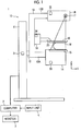
- FIG. 1 is a schematic configuration diagram of a radiation imaging display system to which an image display apparatus according to an embodiment of the invention is applied.
- a radiation imaging display system 1 is a mammography imaging apparatus that obtains a plurality of radiation images by imaging a breast M in different imaging directions to generate a two-dimensional radiation image by performing plain radiography for the breast and performing tomosynthesis imaging for the breast.
- the radiation imaging display system 1 comprises an imaging unit 10, a computer (image display apparatus) 2 connected to the imaging unit 10, a monitor (display unit) 3 connected to the computer 2, and an input unit 4.
- the imaging unit 10 comprises a base 11, a rotary shaft 12 that is movable in a vertical direction (Z-direction) and is rotatable with respect to the base 11, and an arm unit 13 that is connected to the base 11 through the rotary shaft 12.
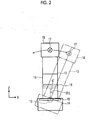
- the arm unit 13 viewed in a right direction (Y-direction) in Fig. 1 is shown.
- the arm unit 13 is in a shape of "C", and an imaging stand 14 is attached to one end part 13A thereof, and a radiation irradiation unit 16 is attached to the other end part 13B thereof to face the imaging stand 14.
- the arm unit 13 is configured so that the end part 13A to which the imaging stand 14 is attached and the end part 13B to which the radiation irradiation unit 16 is attached are integrally rotatable and only the end part 13B to which the radiation irradiation unit 16 is attached is rotatable.
- the imaging stand 14 and the radiation irradiation unit 16 are integrally rotatable, and only the radiation irradiation unit 16 is rotatable in a state where the imaging stand 14 is fixed.
- a rotational position where the arm unit 13 is parallel to the base 11 is set as a 0 degree, and a state where the arm unit 13 integrally rotates the imaging stand 14 and the radiation irradiation unit 16 clockwise by ⁇ 0 degrees is indicated by a virtual line.
- the rotation and the vertical movement of the arm unit 13 are controlled by an arm controller 31 that is assembled in the base 11.
- a radiation detector 15 such as a flat panel detector, and a detector controller 33 that controls readout of a charge signal from the radiation detector 15 are provided.
- a circuit board where a charge amplifier that converts the charge signal read out from the radiation detector 15 into a voltage signal, a correlated double sampling circuit that samples the voltage signal output from the charge amplifier, an analog to digital (AD) conversion unit that converts the voltage signal to a digital signal, and the like are provided is also provided, for example.
- a charge amplifier that converts the charge signal read out from the radiation detector 15 into a voltage signal
- a correlated double sampling circuit that samples the voltage signal output from the charge amplifier
- an analog to digital (AD) conversion unit that converts the voltage signal to a digital signal, and the like are provided is also provided, for example.
- the radiation detector 15 is able to repeatedly perform recording and readout of a radiation image, which may employ a so-called direct type radiation detector that directly receives irradiation of radiation to generate charges, or may employ a so-called indirect type radiation detector that once converts radiation into visible light and converts the visible light into a charge signal. Further, as a method for reading out the radiation image signal, a so-called TFT (thin film transistor) readout method for reading out the radiation image signal by turning on and off a TFT switch, or a so-called optical readout method for reading out the radiation image signal by irradiating readout light is preferably used, but the present disclosure is not limited thereto, and other methods may be used.
- TFT thin film transistor
- a radiation source 17 and a radiation source controller 32 are provided inside the radiation irradiation unit 16.
- the radiation source controller 32 controls a timing when radiation is emitted from the radiation source 17, and radiation generating conditions in the radiation source 17 (a tube current, a period of time, a tube current time product, and the like).
- a compression plate 18 that is arranged above the imaging stand 14 to squeeze and press a breast, a support portion 20 that supports the compression plate 18, and a moving mechanism 19 that moves the support portion 20 in the vertical direction (Z-direction) are provided.
- the position and a compression pressure of the compression plate 18 are controlled by a compression plate controller 34.
- the computer 2 comprises a central processing unit (CPU), a storage device such as a semiconductor memory, a hard disk or a solid state drive (SSD), and the like, and by such hardware, a control unit 21, a radiation image storage unit 22, a reconstruction unit 23, a depth map creating unit 24, a display control unit 25, a storage unit 26 as shown in Fig. 3 are configured.
- CPU central processing unit
- storage device such as a semiconductor memory, a hard disk or a solid state drive (SSD), and the like
- control unit 21 a radiation image storage unit 22
- a reconstruction unit 23 a depth map creating unit 24
- a display control unit 25 as shown in Fig. 3 are configured.
- the control unit 21 outputs a predetermined control signal to various controllers 31 to 34to control the entire apparatus.
- the radiation image storage unit 22 stores a plurality of radiation images detected by the radiation detector 15 by performing imaging in a predetermined imaging direction while rotating both the end parts 13A and 13B of the arm unit 13.
- CC craniocaudal
- ML mediolateral
- MLO mediolateral oblique
- Fig. 1 shows positioning in a case where the craniocaudal (CC) imaging is performed. Further, in this embodiment, it is not necessary to perform all of the CC imaging, the ML imaging, and MLO imaging, and at least one thereof may be performed.
- a plurality of radiation images detected by the radiation detector 15 through imaging in a plurality of imaging directions with an interval of a predetermined angle ⁇ 1 by rotating only the end part 13B to which the radiation irradiation unit 16 is attached, that is, through tomosynthesis imaging, are also stored.
- a plurality of radiation images are acquired by performing the tomosynthesis imaging, and tomographic images of the breast M generated from the plurality of radiation images and a two-dimensional radiation image acquired by plain radiography are displayed.
- the depth map creating unit 24 creates a plurality of depth maps in which each position on a two-dimensional radiation image acquired in each of the imaging directions and depth information indicating a depth directional position from a reference position of a tomographic plane corresponding to each position are associated with each other while changing a correspondence relationship between each position on the two-dimensional radiation image and the depth information.
- the depth map creating unit 24 divides the two-dimensional radiation image GO into a plurality of regions, and obtains a correlation between each region obtained by the division and the plurality of tomographic images Di for each frequency component. For example, as shown in Fig. 6 , the two-dimensional radiation image GO is divided into regions of 6 ⁇ 8, and with respect to the divided one region A1, a correlation between the divided one region A1 and the plurality of tomographic images Di is obtained, for each frequency component. Further, depths, from the reference position, of the tomographic planes of the tomographic images Di including a region where the correlation becomes the largest are associated with the position of the region A1 to create a plurality of depth maps.
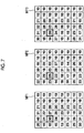
- Fig. 7 is a diagram showing a depth map.
- a bandwidth of a frequency component of an image is divided into three portions, and a high-frequency component depth map MP1, a medium-frequency component depth map MP2, and a low-frequency component depth map MP3 are created in order from the highest frequency component.
- the high-frequency component depth map MP1 associated with 30mm is created at the position of the region A1.
- the medium-frequency component depth map MP2 associated with 25mm is created at the position of the region A1.
- the low-frequency component depth map MP3 associated with 20 mm is created at the position of the region A1.
- a predetermined depth for example, 10 mm
- the created depth maps MP1 to MP3 are stored in the storage unit 26.
- Lesions detected in the two-dimensional radiation image G0 may be divided for each frequency component in accordance with their structures and sizes. For example, a calcification appears as a high-frequency component in the two-dimensional radiation image G0, a spicule appears as a medium-frequency component in the two-dimensional radiation image G0, and a tumor appears as a low-frequency component in the two-dimensional radiation image G0.
- the plurality of depth maps MP1 to MP3 for each frequency component even in a case where a plurality of structures (for example, the calcification, the spicule, the tumor, and the like) are displayed in an overlapping manner at the same region of the two-dimensional radiation image G0, it is possible to specify the depth of a desired structure by selecting a corresponding depth map.
- a plurality of structures for example, the calcification, the spicule, the tumor, and the like
- the depth maps MP1 to MP3 are created, for each frequency component, by associating a position of each region on the two-dimensional radiation image GO with depth information indicating a depth directional position of a tomographic plane corresponding to the position of each region, but instead, may be created by associating a position of each pixel on the two-dimensional radiation image with depth information indicating a depth directional position of a tomographic plane corresponding to the position of each pixel.
- the depth maps may be created by setting a region of a predetermined size centering around a target pixel on the two-dimensional radiation image, obtaining a correlation between the region and the tomographic images Di, and associating the depth, from the reference position, of a tomographic plane of a tomographic image Di including a region where the correlation becomes the largest with the position of the target pixel for which the region is set.
- depth maps MP may be generated by associating the position of each pixel on the two-dimensional radiation image GO with the depth information indicating the depth directional position of the tomographic plane corresponding to the position of each pixel.
- a projection ray of radiation passing through the pixel position may be specified.
- a position on a tomographic image Di through which the projection ray passes may be specified.
- the plurality of depth maps MP1 to MP3 may be created for each frequency component by associating a depth directional position of a tomographic plane of a tomographic image having a maximum pixel value, for example, among the plurality of tomographic images Di on the projection ray, with the pixel position where the projection ray passes.
- the two-dimensional radiation image GO is divided into regions of 6 ⁇ 8, but for example, divided regions divided into 10 pixels ⁇ 10 pixels, 1 cm ⁇ 1 cm, or the like may be a predetermined size.
- the bandwidth of the frequency component of the image is divided into three portions to create three types of depth maps MP1 to MP3, but instead, two, four or more types of depth maps may be created.
- a known region extraction process may be performed with respect to the two-dimensional radiation image G0, and a plurality of depth maps may be created for each object in the image.
- a plurality of depth maps may be created for each lesion of the breast M (for example, calcification, spicule, tumor, and the like).
- the depth of each region in the depth maps may be obtained for each pixel included in each region, and an average value or a mode of the obtained depths in each region may be set to the depth of the region to create the depth maps.
- the display control unit 25 displays a two-dimensional radiation image in a designated imaging direction on the monitor 3 in accordance with an instruction from the input unit 4. Further, the display control unit 25 displays tomographic images on the monitor 3 with reference to any one of the depth maps MP1 to MP3in accordance with an instruction from the input unit 4. The display of the tomographic images will be described later.
- the monitor 3 is configured of a known display device such as a cathode ray tube (CRT), or a liquid crystal display, and displays the two-dimensional radiation image GO and the tomographic images Di output from the computer 2.
- a known display device such as a cathode ray tube (CRT), or a liquid crystal display
- the input unit 4 is configured of a pointing device such as a keyboard or a mouse, for example, and receives input of imaging conditions, input of an imaging start instruction, or the like, from an operator.
- a pointing device such as a keyboard or a mouse
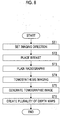
- FIG. 8 is a flowchart illustrating an imaging process performed in a first embodiment.
- an imaging direction is set in accordance with an instruction from the input unit 4 (step ST1).
- the control unit 21 outputs information on the imaging direction instructed from the input unit 4 to the arm controller 31.
- the arm controller 31 outputs a control signal so that the position of the arm unit 13 becomes a position corresponding to the imaging direction designated with respect to the base 11.
- the arm unit 13 causes the imaging stand 14 and the radiation irradiation unit 16 to be integrally rotated.
- the arm controller 31 stops the arm unit 13 in a state where the arm unit 13 is at a position corresponding to the designated imaging direction. In this way, the imaging direction is set. Then, the breast M of a patient is placed on the imaging stand 14, and the breast M is compressed by the compression plate 18 under a predetermined pressure (step ST2). After various imaging conditions are input through the input unit 4, an imaging start instruction is input.
- the control unit 21 outputs a control signal for irradiation of radiation and readout of a radiation image signal to the radiation source controller 32 and the detector controller 33.
- the control signal radiation is emitted from the radiation source 17, a radiation image obtained by imaging the breast M is detected by the radiation detector 15, a radiation image signal is read out through the radiation detector 15 by the detector controller 33, predetermined signal processing is performed for the radiation image signal, and then, the result is stored in the radiation image storage unit 22 of the computer 2 as the two-dimensional radiation image G0.
- tomosynthesis imaging is performed (step ST4).
- the tomosynthesis imaging is performed by irradiating the breast M with radiation while rotating the radiation irradiation unit16 with respect to the imaging stand 14 using the arm unit 13 in a state where the imaging stand14 is fixed.
- the control unit 21 reads out an angle ⁇ 1 for defining a predetermined imaging interval, and outputs information on the read out angle ⁇ 1 to the arm controller 31.
- the arm controller 31 receives the information on the angle ⁇ 1 output from the control unit 21, and the arm controller 31 first outputs a control signal so that the position of the end part of the arm unit 13 to which the radiation irradiation unit 16 is attached is at an initial position of being most inclined with respect to the imaging stand 14.
- the control unit 21 outputs a control signal for irradiation of radiation and readout of a radiation image signal to the radiation source controller 32 and the detector controller 33.
- the control signal radiation is emitted from the radiation source 17, a radiation image obtained by imaging the breast M at the initial position is detected by the radiation detector 15, a radiation image signal is read out through the radiation detector 15 by the detector controller 33, predetermined signal processing is performed for the radiation image signal, and then, the result is stored in the radiation image storage unit 22 of the computer 2 as a radiation image for creating a tomographic image.
- the arm controller 31 outputs a control signal to rotate the arm unit 13 by the degree of ⁇ 1 from the initial position. That is, in this embodiment, the arm controller 31 outputs the control signal to rotate the arm unit 13 by the degree of ⁇ 1 from the initial position toward an end position where final imaging is performed.
- the control unit 21 outputs a control signal for irradiation of radiation and readout of a radiation image signal to the radiation source controller 32 and the detector controller 33.
- control unit 21 outputs a control signal for irradiation of radiation and readout of a radiation image signal to the radiation source controller 32 and the detector controller 33.
- control signal radiation is emitted from the radiation source 17, a radiation image obtained by imaging the breast M at a position that is moved from the position initial by the degree of ⁇ 1 is detected by the radiation detector 15, a radiation image signal is read out by the detector controller 33, predetermined signal processing is performed, and then, the result is stored in the radiation image storage unit 22 of the computer 2 as a radiation image.
- the process is repeatedly performed until the arm unit 13 is rotated to the end position, and thus, a plurality of radiation images are stored in the radiation image storage unit 22.
- the reconstruction unit 23 reconstructs the plurality of radiation images in a reconstruction range of tomographic images of the breast M to generate the plurality of tomographic images Di (step ST5).
- the plurality of tomographic images Di are stored in the radiation image storage unit 22.
- the imaging process is repeatedly performed until the two-dimensional radiation image GO and the tomographic images Di are generated, in all imaging directions that are determined in advance with respect to each of the left and right breasts M.
- the depth map creating unit 24 creates the plurality of depth maps MP1 to MP3 (step ST6) in which each position on the two-dimensional radiation image GO acquired with respect to each of the imaging directions and depth information indicating a depth directional position of a tomographic plane corresponding to each position are associated with each other, for each frequency component, and then, the process is terminated.
- the created depth maps MP1 to MP3 are stored in the storage unit 26.
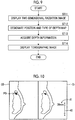
- Fig. 9 is a flowchart of an image display process performed in this embodiment.
- the display control unit 25 reads out the two-dimensional radiation image G0 in the designated imaging direction from the radiation image storage unit 22, and displays the result on the monitor 3 (step ST11).
- the input unit 4 receives designation of a position in the two-dimensional radiation image G0 and the type of a depth map (step ST12).
- the designation of the depth map in the input unit 4 may be performed by receiving designation of the depth map on the basis of an input method at the time of the designation of the position.
- the high-frequency component depth map MP1 may be designated in a case where the position is designated through a left click
- the medium-frequency component depth map MP2 may be designated in a case where the position is designated through a wheel click
- the low-frequency component depth map MP3 may be designated in a case where the position is designated through a right click.
- a calcification depth map MP1 may be designated in a case where the position is designated through a left click
- a spicule depth map MP2 may be designated in a case where the position is designated through a wheel click
- a tumor depth map MP3 may be designated in a case where the position is designated through a right click.
- the designation of the type of the depth map may be received in accordance with a right click, a left click, or a left and right simultaneous click, or may be received in accordance with the number of left clicks (for example, 1 click, 2 clicks, 3 clicks, or the like).
- a user may receive the designation of the type of the depth map on the basis of a structure (object) of a region designated on the two-dimensional radiation image G0.
- the display control unit 25 acquires depth information corresponding to the position designated on the two-dimensional radiation image GO with reference to the selected depth map (step ST13), and displays the tomographic image Di on a tomographic plane corresponding to the acquired depth information on the monitor 3 (step ST14), and then, the process is terminated.
- Fig. 10 is a diagram showing an image displayed on the monitor 3.
- the two-dimensional radiation image G0 is displayed in a left region of a screen of the monitor 3, and the tomographic images Di corresponding to the position P0 designated on the two-dimensional radiation image GO are displayed in the vicinity of the two-dimensional radiation image G0, specifically, in a right region of the two-dimensional radiation image G0.
- the high-frequency component depth map MP1 is designated from the plurality of depth maps MP1 to MP3 and the position designated in the two-dimensional radiation image GO corresponds to a region surrounded by a thick line of the high-frequency component depth map MP1 shown in Fig.
- a tomographic image on a tomographic plane corresponding to the depth of 30 mm is displayed on the monitor 3.
- tomographic planes to be displayed may be sequentially switched in accordance with an instruction through the input unit 4, and the tomographic images may be displayed as a motion picture in which the tomographic planes are sequentially switched.
- a scale 40 indicating a depth directional position of a tomographic plane that is being displayed in all tomographic planes and a numerical value 41 indicating the depth of the tomographic plane are displayed in parallel.
- a region of a predetermined range including the position designated in the two-dimensional radiation image GO may be cut out from the corresponding tomographic image Di, and a cut-out tomographic image Dia may be displayed on the two-dimensional radiation image G0 in an overlapping manner.
- the tomographic image Dia may be displayed as a motion picture, or may be displayed together with the scale 40 indicating the depth directional position on the tomographic plane and the numerical value 41 indicating the depth of the tomographic plane.
- the region of the predetermined range including the position designated in the two-dimensional radiation image GO may be cut out from the corresponding tomographic image Di, regions corresponding to the cut-out region with respect to tomographic images of a plurality of tomographic planes that are before and behind adjacent to the tomographic plane corresponding to the designated position may be cut out, and tomographic images Dia+2, Dia+1, Dia, and Dia-1 of the plurality of cut-out tomographic planes may be displayed in parallel.
- numerical values indicating the depths of the plurality of tomographic planes may be displayed together.
- an interval of tomographic planes to be displayed, as well as the adjacent tomographic planes may be a set as a predetermined interval (for example, 5 mm).
- a plurality of depth maps in which each position on the two-dimensional radiation image GO and depth information indicating a depth directional position of a tomographic plane corresponding to each position are associated with each other are created while changing a correspondence relationship between each position on the two-dimensional radiation image and the depth information, on the basis of the two-dimensional radiation image GO and the plurality of tomographic images Di of the same object. Accordingly, in performing image diagnosis by performing cross reference between the two-dimensional radiation image GO and the tomographic images Di, it is possible to easily designate the position of a lesion by first referring to the two-dimensional radiation image G0.
- any one of the plurality of depth maps MP1 to MP3 corresponding to the type of a lesion it is possible to rapidly specify the tomographic images Di of tomographic planes corresponding to the position of a designated lesion. Accordingly, it is possible to rapidly display the specified tomographic images Di together with the two-dimensional radiation image G0. From the above description, even in a case where a plurality of structures (for example, calcification, spicule, tumor, and the like) are displayed in an overlapping manner at the same region of the two-dimensional radiation image G0, it is possible to perform image diagnosis with high efficiency by performing cross reference between the two-dimensional radiation image GO and the tomographic images Di.
- a plurality of structures for example, calcification, spicule, tumor, and the like
- the two-dimensional radiation image GO into a plurality of regions and creating the depth maps MP in which a position of each region on the two-dimensional radiation image GO and depth information corresponding to the position of each region are associated with each other, even in a case where an operator designates as a rough position in designating a region-of-interest, it is possible to stably display a tomographic image of a desired tomographic plane.
- depth maps MP are created in association with all regions of the two-dimensional radiation image G0, but for example, a region where the breast M in the two-dimensional radiation image GO is included may be extracted, and the plurality of depth maps MP1 to MP3 may be created only with respect to the region where the breast M is included.
- the plurality of depth maps MP1 to MP3 may be created only with respect to the region where the breast M is included.
- a warning may be given that there is no corresponding tomographic image at the position, or a tomographic image corresponding to a central tomographic plane among the plurality of tomographic images Di may be displayed.
- an image obtained by plain radiography is used as the two-dimensional radiation image G0, but instead, a composite two-dimensional radiation image obtained by combining the plurality of tomographic images Di may be used.
- a method for generating the composite two-dimensional radiation image for example, a method for generating a maximum intensity projection (MIP) image as the composite two-dimensional radiation image from the plurality of tomographic images Di using a maximum intensity projection (MIP) method may be used.
- MIP maximum intensity projection
- an imaging time of the plain radiography and an imaging time of the tomosynthesis imaging become different from each other.
- the degree of compression of the breast M varies, or an imaging position slightly varies, and thus, there is a concern that geometric shapes of the breast M included in the two-dimensional radiation image G0 and the breast M included in the tomographic images Di become different from each other.
- tomographic images may be generated by performing CT imaging in which a radiation source and a radiation detector are disposed to face each other with a subject being placed at the center, the set of the radiation source and the radiation detector is turned around the subject, radiation is irradiated at various angles to capture a plurality of radiation images, and tomographic images are reconstructed using the radiation images at the respective angles to display an unspecified cross section.
- the radiation imaging display system to which the image display apparatus of the invention is applied is used as an apparatus that captures a radiation image of a breast, but in this case, a subject is not limited to the breast, and for example, a radiation imaging display system for imaging a chest portion, a head portion, or the like may be used. Furthermore, appropriate modifications may be made without departing from the concept of the invention.
Landscapes
- Engineering & Computer Science (AREA)
- Health & Medical Sciences (AREA)
- Life Sciences & Earth Sciences (AREA)
- Medical Informatics (AREA)
- Physics & Mathematics (AREA)
- General Health & Medical Sciences (AREA)
- Radiology & Medical Imaging (AREA)
- Nuclear Medicine, Radiotherapy & Molecular Imaging (AREA)
- Pathology (AREA)
- Surgery (AREA)
- Biophysics (AREA)
- Optics & Photonics (AREA)
- Veterinary Medicine (AREA)
- Theoretical Computer Science (AREA)
- Biomedical Technology (AREA)
- Heart & Thoracic Surgery (AREA)
- Molecular Biology (AREA)
- High Energy & Nuclear Physics (AREA)
- Animal Behavior & Ethology (AREA)
- General Physics & Mathematics (AREA)
- Public Health (AREA)
- Computer Vision & Pattern Recognition (AREA)
- Human Computer Interaction (AREA)
- Quality & Reliability (AREA)
- Dentistry (AREA)
- Oral & Maxillofacial Surgery (AREA)
- Apparatus For Radiation Diagnosis (AREA)
Abstract
Description
- The present disclosure relates to an image display apparatus, a radiation imaging display system, an image display method, and an image display program.
- In displaying a medical image such as a radiation image to perform image diagnosis, a technique for performing cross reference between a two-dimensional radiation image acquired by plain radiography and tomographic images acquired through tomography using a computed tomography (CT) apparatus, a magnetic resonance imaging (MRI) apparatus, a tomosynthesis imaging apparatus, or the like has been used. For example, in order to perform image diagnosis of a breast, a technique for confirming of the presence or absence of a lesion (tumor or calcification) in the breast by perform cross reference between two-dimensional radiation images acquired by performing plain radiography in a variety of imaging directions, such as a craniocaudal (CC) imaging for performing imaging by irradiating radiation from an upper side, mediolateral (ML) imaging for performing imaging by irradiating radiation from a lateral side, a mediolateral oblique (MLO) imaging for performing imaging by irradiating radiation in an oblique direction, or the like, and tomographic images generated by reconstructing a plurality of radiation images acquired through tomosynthesis imaging in the variety of imaging directions has been used.
- The tomosynthesis imaging is a method for performing imaging by irradiating radiation to a subject in a plurality of different directions while moving a radiation source and reconstructing an image acquired in this way to obtain an image in which a desired cross-section is emphasized. In the tomosynthesis imaging, in accordance with characteristics of an imaging apparatus and necessary tomographic images, a plurality of radiation images are acquired by imaging the subject at a plurality of irradiation positions having different irradiation angles by moving the radiation source in parallel with a radiation detector or moving the radiation source to draw an arc of a circle or an ellipse, and tomographic images are generated by reconstructing these radiation images using a back-projection method such as a simple back-projection method or a filtered back-projection method.
- Here, a two-dimensional radiation image has merits in that perspicuity is excellent, sharpness is high, and it is easy to compare the two-dimensional radiation image with a previous image, as compared with a tomographic image. Accordingly, cross reference between the two-dimensional radiation image and the tomographic image is performed by performing image analysis by displaying the two-dimensional radiation image on a display device such as a liquid crystal monitor, designating a position where it is considered that a lesion is present on the two-dimensional radiation image through clicking or the like, and displaying the tomographic image obtained by enlarging a region in the vicinity of the lesion. Further, there is also a case where cross reference is performed by simultaneously displaying a two-dimensional radiation image and tomographic images corresponding to an imaging direction of the two-dimensional radiation image. In either case, the tomographic image is automatically or manually displayed while switching tomographic planes.
- A plurality of tomographic images are acquired by the tomography imaging such as the above-mentioned tomosynthesis imaging, but since there are a tomographic image of a tomographic plane on which a lesion or the like is included and a tomographic image of a tomographic plane on which the lesion is not included, a user such as a doctor who performs image analysis needs to perform interpretation while switching the plurality of tomographic images. Accordingly, in a case where image diagnosis is performed by performing cross reference between two-dimensional radiation images and tomographic images, its operation is troublesome as compared with a case where only the two-dimensional radiation images are used, and consequently, it takes long time to perform diagnosis.
- Accordingly, a technique for creating a depth map in which each position on a two-dimensional radiation image and depth information indicating a depth directional position of a tomographic plane corresponding to each position are associated with each other, and extracting and displaying, in a case where a reference position is designated in the two-dimensional radiation image, a tomographic image corresponding to the depth of the reference position has been proposed (see
WO14/203531A - However, in a two-dimensional radiation image, since a plurality of structures are displayed in an overlapping manner in a depth direction of a subject, in the technique of
WO14/203531A - The present disclosure has been made in view of the above circumstances, and an object of the invention is to provide an image display apparatus, a radiation imaging display system, an image display method, and an image display program capable of accurately displaying, in performing image diagnosis by performing cross reference between a two-dimensional radiation image and a tomographic image, a tomographic image corresponding to a designated position on the two-dimensional radiation image.
- According to an aspect of the invention, there is provided an image display apparatus comprising: a depth map creating unit that creates, on the basis of a two-dimensional radiation image and a plurality of tomographic images for the same subject, a plurality of depth maps in which each position on the two-dimensional radiation image and depth information indicating a depth directional position of a tomographic plane corresponding to each position are associated with each other while changing a correspondence relationship between each position on the two-dimensional radiation image and the depth information.
- In the image display apparatus according to the present disclosure, the depth map creating unit may create the plurality of depth maps for each frequency component of the two-dimensional radiation image and the plurality of tomographic images.
- In the image display apparatus according to the present disclosure, the depth map creating unit may create the plurality of depth maps for each object in the two-dimensional radiation image and the plurality of tomographic images.
- In the image display apparatus according to the present disclosure, the depth map creating unit may create the depth maps by associating each position on the two-dimensional radiation image and the depth information indicating the depth directional position of the tomographic plane corresponding to each position on the basis of a correlation between each position on the two-dimensional radiation image and the plurality of tomographic images.
- Further, in the image display apparatus according to the present disclosure, the depth map creating unit may divide the two-dimensional image into a plurality of regions, and may create the depth maps by associating a position of each region on the two-dimensional radiation image and the depth information indicating the depth directional position of the tomographic plane corresponding to the position of each region.
- The image display apparatus according to the present disclosure may further comprise a display control unit that specifies depth information on a reference position in the two-dimensional radiation image with reference to the depth maps and displays a tomographic image of a tomographic plane indicated by the specified depth information on a display unit.
- Further, the image display apparatus according to the present disclosure may further comprise: an input unit that receives designation of any position on the two-dimensional radiation image displayed on the display unit, in which the display control unit displays the tomographic images on the display unit using the designated position as the reference position.
- Further, in the image display apparatus according to the present disclosure, the display control unit may determine the depth map to be referred to from the plurality of depth maps on the basis of an input method in a case where the input unit receives the designation.
- In addition, in the image display apparatus according to the present disclosure, the display control unit may determine the depth map to be referred to from the plurality of depth maps on the basis of an object at the designated position on the two-dimensional radiation image.
- According to another aspect of the present disclosure, there is provided a radiation imaging display system comprising: an imaging unit that acquires a two-dimensional radiation image and a plurality of tomographic images for the same subject; and the image display apparatus according to the present disclosure.
- According to still another aspect of the present disclosure, there is provided an image display method comprising: creating, on the basis of a two-dimensional radiation image and a plurality of tomographic images for the same subject, a plurality of depth maps in which each position on the two-dimensional radiation image and depth information indicating a depth directional position of a tomographic plane corresponding to each position are associated with each other while changing a correspondence relationship between each position on the two-dimensional radiation image and the depth information.
- According to still another aspect of the present disclosure, there is provided an image display program for causing a computer to execute a procedure of creating, on the basis of a two-dimensional radiation image and a plurality of tomographic images for the same subject, a plurality of depth maps in which each position on the two-dimensional radiation image and depth information indicating a depth directional position of a tomographic plane corresponding to each position are associated with each other while changing a correspondence relationship between each position on the two-dimensional radiation image and the depth information.
- According to the present disclosure, it is possible to provide an image display apparatus, a radiation imaging display system, an image display method, and an image display program capable of accurately displaying, in performing image diagnosis by performing cross reference between a two-dimensional radiation image and tomographic images, a tomographic image corresponding to a designated position on the two-dimensional radiation image.
-
-
Fig. 1 is a schematic configuration diagram of a radiation imaging display system to which an image display apparatus according to an embodiment of the invention is applied. -
Fig. 2 is a diagram showing an arm unit of the radiation imaging display system shown inFig. 1 , seen in a right direction ofFig. 1 . -
Fig. 3 is a block diagram showing a schematic internal configuration of a computer of the radiation imaging display system shown inFig. 1 . -
Fig. 4 is a diagram showing a plurality of imaging directions. -
Fig. 5 is a diagram showing a reconstruction range of a tomographic image. -
Fig. 6 is a diagram for explaining creation of a depth map. -
Fig. 7 is a diagram showing the depth map. -
Fig. 8 is a flowchart showing processes performed in a first embodiment. -
Fig. 9 is a flowchart of an image display process performed in the first embodiment. -
Fig. 10 is a diagram showing an example of an image displayed on a monitor. -
Fig. 11 is a diagram showing an example of an image displayed on the monitor. -
Fig. 12 is a diagram showing an example of an image displayed on the monitor. - Hereinafter, embodiments of the invention will be described with reference to the accompanying drawings.
Fig. 1 is a schematic configuration diagram of a radiation imaging display system to which an image display apparatus according to an embodiment of the invention is applied. A radiationimaging display system 1 is a mammography imaging apparatus that obtains a plurality of radiation images by imaging a breast M in different imaging directions to generate a two-dimensional radiation image by performing plain radiography for the breast and performing tomosynthesis imaging for the breast. As shown inFig. 1 , the radiationimaging display system 1 comprises animaging unit 10, a computer (image display apparatus) 2 connected to theimaging unit 10, a monitor (display unit) 3 connected to thecomputer 2, and aninput unit 4. - The
imaging unit 10 comprises abase 11, arotary shaft 12 that is movable in a vertical direction (Z-direction) and is rotatable with respect to thebase 11, and anarm unit 13 that is connected to thebase 11 through therotary shaft 12. InFig. 2 , thearm unit 13 viewed in a right direction (Y-direction) inFig. 1 is shown. - The
arm unit 13 is in a shape of "C", and animaging stand 14 is attached to oneend part 13A thereof, and aradiation irradiation unit 16 is attached to theother end part 13B thereof to face theimaging stand 14. Thearm unit 13 is configured so that theend part 13A to which theimaging stand 14 is attached and theend part 13B to which theradiation irradiation unit 16 is attached are integrally rotatable and only theend part 13B to which theradiation irradiation unit 16 is attached is rotatable. Thus, the imaging stand 14 and theradiation irradiation unit 16 are integrally rotatable, and only theradiation irradiation unit 16 is rotatable in a state where theimaging stand 14 is fixed. InFig. 2 , in a case where a clockwise rotation ofFig. 2 is positive, a rotational position where thearm unit 13 is parallel to thebase 11 is set as a 0 degree, and a state where thearm unit 13 integrally rotates the imaging stand 14 and theradiation irradiation unit 16 clockwise by θ0 degrees is indicated by a virtual line. The rotation and the vertical movement of thearm unit 13 are controlled by anarm controller 31 that is assembled in thebase 11. - Inside the imaging stand 14, a
radiation detector 15 such as a flat panel detector, and adetector controller 33 that controls readout of a charge signal from theradiation detector 15 are provided. - Further, inside the imaging stand 14, a circuit board where a charge amplifier that converts the charge signal read out from the
radiation detector 15 into a voltage signal, a correlated double sampling circuit that samples the voltage signal output from the charge amplifier, an analog to digital (AD) conversion unit that converts the voltage signal to a digital signal, and the like are provided is also provided, for example. - The
radiation detector 15 is able to repeatedly perform recording and readout of a radiation image, which may employ a so-called direct type radiation detector that directly receives irradiation of radiation to generate charges, or may employ a so-called indirect type radiation detector that once converts radiation into visible light and converts the visible light into a charge signal. Further, as a method for reading out the radiation image signal, a so-called TFT (thin film transistor) readout method for reading out the radiation image signal by turning on and off a TFT switch, or a so-called optical readout method for reading out the radiation image signal by irradiating readout light is preferably used, but the present disclosure is not limited thereto, and other methods may be used. - Inside the
radiation irradiation unit 16, aradiation source 17 and aradiation source controller 32 are provided. Theradiation source controller 32 controls a timing when radiation is emitted from theradiation source 17, and radiation generating conditions in the radiation source 17 (a tube current, a period of time, a tube current time product, and the like). - Further, at a central portion of the
arm unit 13, acompression plate 18 that is arranged above the imaging stand 14 to squeeze and press a breast, asupport portion 20 that supports thecompression plate 18, and a movingmechanism 19 that moves thesupport portion 20 in the vertical direction (Z-direction) are provided. The position and a compression pressure of thecompression plate 18 are controlled by acompression plate controller 34. - The
computer 2 comprises a central processing unit (CPU), a storage device such as a semiconductor memory, a hard disk or a solid state drive (SSD), and the like, and by such hardware, acontrol unit 21, a radiationimage storage unit 22, areconstruction unit 23, a depthmap creating unit 24, adisplay control unit 25, astorage unit 26 as shown inFig. 3 are configured. - The
control unit 21 outputs a predetermined control signal tovarious controllers 31 to 34to control the entire apparatus. - The radiation image storage unit 22stores a plurality of radiation images detected by the
radiation detector 15 by performing imaging in a predetermined imaging direction while rotating both theend parts arm unit 13. As the imaging direction of the breast M, there are craniocaudal (CC) imaging for performing imaging by irradiating radiation from an upper side, mediolateral (ML) imaging for performing imaging by irradiating radiation from a lateral side, a mediolateral oblique (MLO) imaging for performing imaging by irradiating radiation in an oblique direction, and thearm unit 13 is rotated to be positioned in accordance with these imaging directions to perform imaging.Fig. 1 shows positioning in a case where the craniocaudal (CC) imaging is performed. Further, in this embodiment, it is not necessary to perform all of the CC imaging, the ML imaging, and MLO imaging, and at least one thereof may be performed. - In addition, in this embodiment, as shown in
Fig. 4 , a plurality of radiation images detected by theradiation detector 15 through imaging in a plurality of imaging directions with an interval of a predetermined angle θ1 by rotating only theend part 13B to which theradiation irradiation unit 16 is attached, that is, through tomosynthesis imaging, are also stored. In this embodiment, in each of the imaging directions, a plurality of radiation images are acquired by performing the tomosynthesis imaging, and tomographic images of the breast M generated from the plurality of radiation images and a two-dimensional radiation image acquired by plain radiography are displayed. - The
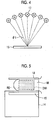
reconstruction unit 23 reconstructs the plurality of radiation images stored in the radiationimage storage unit 22 to generate a tomographic image in which a desired tomographic plane of the breast M is emphasized. Specifically, thereconstruction unit 23 generates a tomographic image by reconstructing these radiation images using back-projection methods such as a simple back-projection method or a filtered back-projection technique. As shown inFig. 5 , the reconstruction unit 23generates a tomographic image at each of a plurality of tomographic planes DMi (i = 1 to n, where n represents the number of tomographic planes) parallel to a detection surface of theradiation detector 15 in a reconstruction range R0 that is predetermined in the breast M. - The depth
map creating unit 24 creates a plurality of depth maps in which each position on a two-dimensional radiation image acquired in each of the imaging directions and depth information indicating a depth directional position from a reference position of a tomographic plane corresponding to each position are associated with each other while changing a correspondence relationship between each position on the two-dimensional radiation image and the depth information.Fig. 6 is a diagram for describing creation of a depth map. In this embodiment, as described above, in one imaging direction, a plurality of tomographic images Di (i = 1 to n, where n represents the number of tomographic planes) and one two-dimensional radiation image GO are stored in the radiationimage storage unit 22. In this embodiment, for example, an example in which an interval between the tomographic planes is 1mmand the tomographic images Di are generated on the tomographic planes DMi from a depth of 10 mm to a depth of 40 mm at 1 mm intervals toward theradiation source 17 using the detection surface of theradiation detector 15 as a reference position is shown, but the invention is not limited thereto. - The depth
map creating unit 24 divides the two-dimensional radiation image GO into a plurality of regions, and obtains a correlation between each region obtained by the division and the plurality of tomographic images Di for each frequency component. For example, as shown inFig. 6 , the two-dimensional radiation image GO is divided into regions of 6 × 8, and with respect to the divided one region A1, a correlation between the divided one region A1 and the plurality of tomographic images Di is obtained, for each frequency component. Further, depths, from the reference position, of the tomographic planes of the tomographic images Di including a region where the correlation becomes the largest are associated with the position of the region A1 to create a plurality of depth maps. - In this way, by creating the depth map in which each position on the two-dimensional radiation image and the depth information indicating the depth directional position of the tomographic plane corresponding to each position are associated with each other, on the basis of the correlation between each position on the two-dimensional radiation image and the plurality of tomographic images, it is possible to easily associate each position on the two-dimensional radiation image and the depth directional position of the tomographic plane.
-
Fig. 7 is a diagram showing a depth map. For example, with respect to the 2-dimensional radiation image GO and the plurality of tomographic images Di, a bandwidth of a frequency component of an image is divided into three portions, and a high-frequency component depth map MP1, a medium-frequency component depth map MP2, and a low-frequency component depth map MP3 are created in order from the highest frequency component. - Specifically, in a high-frequency component image of the two-dimensional radiation image G0, in a case where the depth of a high-frequency component tomographic image including a region where a correlation with a region A1 in
Fig. 6 becomes highest is 30 mm, the high-frequency component depth map MP1 associated with 30mm is created at the position of the region A1. Further, in a medium-frequency component image of the two-dimensional radiation image G0, in a case where the depth of a medium-frequency component tomographic image including the region where the correlation with the region A1 inFig. 6 becomes highest is 25 mm, the medium-frequency component depth map MP2 associated with 25mm is created at the position of the region A1. In addition, in a low-frequency component image of the two-dimensional radiation image G0, in a case where the depth of a low-frequency component tomographic image including the region where the correlation with the region A1 inFig. 6 becomes highest is 20 mm, the low-frequency component depth map MP3 associated with 20 mm is created at the position of the region A1. In the depth maps MP1 to MP3, a predetermined depth (for example, 10 mm) may be associated with a region that does not include the breast M in the two-dimensional radiation image G0. The created depth maps MP1 to MP3 are stored in thestorage unit 26. - Lesions detected in the two-dimensional radiation image G0 (for example, calcification, spicule, tumor, and the like) may be divided for each frequency component in accordance with their structures and sizes. For example, a calcification appears as a high-frequency component in the two-dimensional radiation image G0, a spicule appears as a medium-frequency component in the two-dimensional radiation image G0, and a tumor appears as a low-frequency component in the two-dimensional radiation image G0. Accordingly, by creating the plurality of depth maps MP1 to MP3 for each frequency component, even in a case where a plurality of structures (for example, the calcification, the spicule, the tumor, and the like) are displayed in an overlapping manner at the same region of the two-dimensional radiation image G0, it is possible to specify the depth of a desired structure by selecting a corresponding depth map.
- The depth maps MP1 to MP3 are created, for each frequency component, by associating a position of each region on the two-dimensional radiation image GO with depth information indicating a depth directional position of a tomographic plane corresponding to the position of each region, but instead, may be created by associating a position of each pixel on the two-dimensional radiation image with depth information indicating a depth directional position of a tomographic plane corresponding to the position of each pixel. In this case, the depth maps may be created by setting a region of a predetermined size centering around a target pixel on the two-dimensional radiation image, obtaining a correlation between the region and the tomographic images Di, and associating the depth, from the reference position, of a tomographic plane of a tomographic image Di including a region where the correlation becomes the largest with the position of the target pixel for which the region is set.
- On the other hand, at the time of acquisition of the two-dimensional radiation image G0 and reconstruction of the plurality of tomographic images Di, a positional relationship between the
radiation source 17 and theradiation detector 15 is known in advance. Thus, on the basis of the positional relationship between theradiation source 17 and theradiation detector 15, depth maps MP may be generated by associating the position of each pixel on the two-dimensional radiation image GO with the depth information indicating the depth directional position of the tomographic plane corresponding to the position of each pixel. In this case, from a certain pixel position on the two-dimensional radiation image G0, and the positional relationship between theradiation source 17 and theradiation detector 15, a projection ray of radiation passing through the pixel position may be specified. If the projection ray can be specified, a position on a tomographic image Di through which the projection ray passes may be specified. Further, the plurality of depth maps MP1 to MP3 may be created for each frequency component by associating a depth directional position of a tomographic plane of a tomographic image having a maximum pixel value, for example, among the plurality of tomographic images Di on the projection ray, with the pixel position where the projection ray passes. - Further, in the above description, the two-dimensional radiation image GO is divided into regions of 6 × 8, but for example, divided regions divided into 10 pixels × 10 pixels, 1 cm × 1 cm, or the like may be a predetermined size. In addition, in the above description, with respect to the two-dimensional radiation image G0 and the plurality of tomographic images Di, the bandwidth of the frequency component of the image is divided into three portions to create three types of depth maps MP1 to MP3, but instead, two, four or more types of depth maps may be created.
- Further, a known region extraction process may be performed with respect to the two-dimensional radiation image G0, and a plurality of depth maps may be created for each object in the image. Specifically, a plurality of depth maps may be created for each lesion of the breast M (for example, calcification, spicule, tumor, and the like). In this case, the depth of each region in the depth maps may be obtained for each pixel included in each region, and an average value or a mode of the obtained depths in each region may be set to the depth of the region to create the depth maps. In the case of such an embodiment, similar to the case where the plurality of depth maps MP1 to MP3 are created for each frequency component, even in a case where the plurality of structures (for example, calcification, spicule, tumor, and the like) are displayed in an overlapping manner at the same region of the two-dimensional radiation image G0, it is possible to specify the depth of a desired structure by selecting a corresponding depth map.
- The
display control unit 25 displays a two-dimensional radiation image in a designated imaging direction on themonitor 3 in accordance with an instruction from theinput unit 4. Further, thedisplay control unit 25 displays tomographic images on themonitor 3 with reference to any one of the depth maps MP1 to MP3in accordance with an instruction from theinput unit 4. The display of the tomographic images will be described later. - The
monitor 3 is configured of a known display device such as a cathode ray tube (CRT), or a liquid crystal display, and displays the two-dimensional radiation image GO and the tomographic images Di output from thecomputer 2. - The
input unit 4 is configured of a pointing device such as a keyboard or a mouse, for example, and receives input of imaging conditions, input of an imaging start instruction, or the like, from an operator. - Then, processes performed in this embodiment will be described.
Fig. 8 is a flowchart illustrating an imaging process performed in a first embodiment. First, an imaging direction is set in accordance with an instruction from the input unit 4 (step ST1). Specifically, first, thecontrol unit 21 outputs information on the imaging direction instructed from theinput unit 4 to thearm controller 31. Thearm controller 31 outputs a control signal so that the position of thearm unit 13 becomes a position corresponding to the imaging direction designated with respect to thebase 11. Then, in accordance with the control signal output from thearm controller 31, thearm unit 13 causes theimaging stand 14 and theradiation irradiation unit 16 to be integrally rotated. Thearm controller 31 stops thearm unit 13 in a state where thearm unit 13 is at a position corresponding to the designated imaging direction. In this way, the imaging direction is set. Then, the breast M of a patient is placed on theimaging stand 14, and the breast M is compressed by thecompression plate 18 under a predetermined pressure (step ST2). After various imaging conditions are input through theinput unit 4, an imaging start instruction is input. - In a case where the imaging start instruction is input through the
input unit 4, plain radiography is performed to acquire the two-dimensional radiation image G0 (step ST3). Specifically, in accordance with the imaging start instruction, thecontrol unit 21 outputs a control signal for irradiation of radiation and readout of a radiation image signal to theradiation source controller 32 and thedetector controller 33. In accordance with the control signal, radiation is emitted from theradiation source 17, a radiation image obtained by imaging the breast M is detected by theradiation detector 15, a radiation image signal is read out through theradiation detector 15 by thedetector controller 33, predetermined signal processing is performed for the radiation image signal, and then, the result is stored in the radiationimage storage unit 22 of thecomputer 2 as the two-dimensional radiation image G0. - Then, tomosynthesis imaging is performed (step ST4). The tomosynthesis imaging is performed by irradiating the breast M with radiation while rotating the radiation irradiation unit16 with respect to the imaging stand 14 using the
arm unit 13 in a state where the imaging stand14 is fixed. Specifically, first, thecontrol unit 21 reads out an angle θ1 for defining a predetermined imaging interval, and outputs information on the read out angle θ1 to thearm controller 31. - Further, the
arm controller 31 receives the information on the angle θ1 output from thecontrol unit 21, and thearm controller 31 first outputs a control signal so that the position of the end part of thearm unit 13 to which theradiation irradiation unit 16 is attached is at an initial position of being most inclined with respect to theimaging stand 14. - Then, in a state where the
arm unit 13 is at the initial position in accordance with the control signal output from thearm controller 31, thecontrol unit 21 outputs a control signal for irradiation of radiation and readout of a radiation image signal to theradiation source controller 32 and thedetector controller 33. In accordance with the control signal, radiation is emitted from theradiation source 17, a radiation image obtained by imaging the breast M at the initial position is detected by theradiation detector 15, a radiation image signal is read out through theradiation detector 15 by thedetector controller 33, predetermined signal processing is performed for the radiation image signal, and then, the result is stored in the radiationimage storage unit 22 of thecomputer 2 as a radiation image for creating a tomographic image. - Then, the
arm controller 31 outputs a control signal to rotate thearm unit 13 by the degree of θ1 from the initial position. That is, in this embodiment, thearm controller 31 outputs the control signal to rotate thearm unit 13 by the degree of θ1 from the initial position toward an end position where final imaging is performed. In a state where thearm unit 13 is rotated by the degree of θ1 in accordance with the control signal output from thearm controller 31, thecontrol unit 21 outputs a control signal for irradiation of radiation and readout of a radiation image signal to theradiation source controller 32 and thedetector controller 33. - Specifically, the
control unit 21 outputs a control signal for irradiation of radiation and readout of a radiation image signal to theradiation source controller 32 and thedetector controller 33. In accordance with the control signal, radiation is emitted from theradiation source 17, a radiation image obtained by imaging the breast M at a position that is moved from the position initial by the degree of θ1 is detected by theradiation detector 15, a radiation image signal is read out by thedetector controller 33, predetermined signal processing is performed, and then, the result is stored in the radiationimage storage unit 22 of thecomputer 2 as a radiation image. - Further, the process is repeatedly performed until the
arm unit 13 is rotated to the end position, and thus, a plurality of radiation images are stored in the radiationimage storage unit 22. - Then, the
reconstruction unit 23 reconstructs the plurality of radiation images in a reconstruction range of tomographic images of the breast M to generate the plurality of tomographic images Di (step ST5). The plurality of tomographic images Di are stored in the radiationimage storage unit 22. The imaging process is repeatedly performed until the two-dimensional radiation image GO and the tomographic images Di are generated, in all imaging directions that are determined in advance with respect to each of the left and right breasts M. - Then, the depth
map creating unit 24 creates the plurality of depth maps MP1 to MP3 (step ST6) in which each position on the two-dimensional radiation image GO acquired with respect to each of the imaging directions and depth information indicating a depth directional position of a tomographic plane corresponding to each position are associated with each other, for each frequency component, and then, the process is terminated. The created depth maps MP1 to MP3 are stored in thestorage unit 26. -
Fig. 9 is a flowchart of an image display process performed in this embodiment. In a case where an imaging direction instruction and an image display instruction are input through theinput unit 4, thedisplay control unit 25 reads out the two-dimensional radiation image G0 in the designated imaging direction from the radiationimage storage unit 22, and displays the result on the monitor 3 (step ST11). - Then, the
input unit 4 receives designation of a position in the two-dimensional radiation image G0 and the type of a depth map (step ST12). The designation of the depth map in theinput unit 4 may be performed by receiving designation of the depth map on the basis of an input method at the time of the designation of the position. For example, in a case where a mouse is used as theinput unit 4, the high-frequency component depth map MP1 may be designated in a case where the position is designated through a left click, the medium-frequency component depth map MP2 may be designated in a case where the position is designated through a wheel click, and the low-frequency component depth map MP3 may be designated in a case where the position is designated through a right click. - Instead of the above designation method, in a case where depth maps are created for each lesion of the breast M, a calcification depth map MP1 may be designated in a case where the position is designated through a left click, a spicule depth map MP2 may be designated in a case where the position is designated through a wheel click, and a tumor depth map MP3 may be designated in a case where the position is designated through a right click. Further, with respect to an input method through the mouse, the designation of the type of the depth map may be received in accordance with a right click, a left click, or a left and right simultaneous click, or may be received in accordance with the number of left clicks (for example, 1 click, 2 clicks, 3 clicks, or the like). Further, a user may receive the designation of the type of the depth map on the basis of a structure (object) of a region designated on the two-dimensional radiation image G0.
- The
display control unit 25 acquires depth information corresponding to the position designated on the two-dimensional radiation image GO with reference to the selected depth map (step ST13), and displays the tomographic image Di on a tomographic plane corresponding to the acquired depth information on the monitor 3 (step ST14), and then, the process is terminated. -
Fig. 10 is a diagram showing an image displayed on themonitor 3. As shown inFig. 10 , the two-dimensional radiation image G0 is displayed in a left region of a screen of themonitor 3, and the tomographic images Di corresponding to the position P0 designated on the two-dimensional radiation image GO are displayed in the vicinity of the two-dimensional radiation image G0, specifically, in a right region of the two-dimensional radiation image G0. For example, in a case where the high-frequency component depth map MP1 is designated from the plurality of depth maps MP1 to MP3 and the position designated in the two-dimensional radiation image GO corresponds to a region surrounded by a thick line of the high-frequency component depth map MP1 shown inFig. 7 , since the depth from the reference position is 30 mm, a tomographic image on a tomographic plane corresponding to the depth of 30 mm is displayed on themonitor 3. Here, tomographic planes to be displayed may be sequentially switched in accordance with an instruction through theinput unit 4, and the tomographic images may be displayed as a motion picture in which the tomographic planes are sequentially switched. In the displayed tomographic image Di, ascale 40 indicating a depth directional position of a tomographic plane that is being displayed in all tomographic planes and anumerical value 41 indicating the depth of the tomographic plane are displayed in parallel. - As shown in
Fig. 11 , a region of a predetermined range including the position designated in the two-dimensional radiation image GO may be cut out from the corresponding tomographic image Di, and a cut-out tomographic image Dia may be displayed on the two-dimensional radiation image G0 in an overlapping manner. In this case, the tomographic image Dia may be displayed as a motion picture, or may be displayed together with thescale 40 indicating the depth directional position on the tomographic plane and thenumerical value 41 indicating the depth of the tomographic plane. - Further, as shown in
Fig. 12 , the region of the predetermined range including the position designated in the two-dimensional radiation image GO may be cut out from the corresponding tomographic image Di, regions corresponding to the cut-out region with respect to tomographic images of a plurality of tomographic planes that are before and behind adjacent to the tomographic plane corresponding to the designated position may be cut out, and tomographic images Dia+2, Dia+1, Dia, and Dia-1 of the plurality of cut-out tomographic planes may be displayed in parallel. In this case, numerical values indicating the depths of the plurality of tomographic planes may be displayed together. Further, in this case, an interval of tomographic planes to be displayed, as well as the adjacent tomographic planes, may be a set as a predetermined interval (for example, 5 mm). - As described above, in this embodiment, a plurality of depth maps in which each position on the two-dimensional radiation image GO and depth information indicating a depth directional position of a tomographic plane corresponding to each position are associated with each other are created while changing a correspondence relationship between each position on the two-dimensional radiation image and the depth information, on the basis of the two-dimensional radiation image GO and the plurality of tomographic images Di of the same object. Accordingly, in performing image diagnosis by performing cross reference between the two-dimensional radiation image GO and the tomographic images Di, it is possible to easily designate the position of a lesion by first referring to the two-dimensional radiation image G0. Further, by referring to any one of the plurality of depth maps MP1 to MP3 corresponding to the type of a lesion, it is possible to rapidly specify the tomographic images Di of tomographic planes corresponding to the position of a designated lesion. Accordingly, it is possible to rapidly display the specified tomographic images Di together with the two-dimensional radiation image G0. From the above description, even in a case where a plurality of structures (for example, calcification, spicule, tumor, and the like) are displayed in an overlapping manner at the same region of the two-dimensional radiation image G0, it is possible to perform image diagnosis with high efficiency by performing cross reference between the two-dimensional radiation image GO and the tomographic images Di.
- Further, by dividing the two-dimensional radiation image GO into a plurality of regions and creating the depth maps MP in which a position of each region on the two-dimensional radiation image GO and depth information corresponding to the position of each region are associated with each other, even in a case where an operator designates as a rough position in designating a region-of-interest, it is possible to stably display a tomographic image of a desired tomographic plane.
- In this embodiment, depth maps MP are created in association with all regions of the two-dimensional radiation image G0, but for example, a region where the breast M in the two-dimensional radiation image GO is included may be extracted, and the plurality of depth maps MP1 to MP3 may be created only with respect to the region where the breast M is included. As described above, by creating the depth maps MP1 to MP3 only with respect to the region where the breast M is included, it is possible to shorten a calculation time for creating the depth maps MP1 to MP3. In this case, in a case where a position of an object other than the breast M is indicated in the displayed two-dimensional radiation image G0, a warning may be given that there is no corresponding tomographic image at the position, or a tomographic image corresponding to a central tomographic plane among the plurality of tomographic images Di may be displayed.
- Further, in this embodiment, an image obtained by plain radiography is used as the two-dimensional radiation image G0, but instead, a composite two-dimensional radiation image obtained by combining the plurality of tomographic images Di may be used. As a method for generating the composite two-dimensional radiation image, for example, a method for generating a maximum intensity projection (MIP) image as the composite two-dimensional radiation image from the plurality of tomographic images Di using a maximum intensity projection (MIP) method may be used. For example, in a case where it is determined that a precise examination is necessary as a result of diagnosis using the two-dimensional radiation image G0 acquired through plain radiography in a health checkup and tomographic images are acquired through tomosynthesis imaging in the precise examination, an imaging time of the plain radiography and an imaging time of the tomosynthesis imaging become different from each other. As a result, for example, the degree of compression of the breast M varies, or an imaging position slightly varies, and thus, there is a concern that geometric shapes of the breast M included in the two-dimensional radiation image G0 and the breast M included in the tomographic images Di become different from each other. In such a case, since the positional relationship between the two-dimensional radiation image GO acquired through the plain radiography and the depth maps MP1 to MP3 varies, there is a Concern that each position on the two-dimensional radiation image G0 and the depth information corresponding to each position may not be associated with each other. Accordingly, by creating the depth maps MP1 to MP3 using the composite two-dimensional radiation image obtained by combining the plurality of tomographic images Di as the two-dimensional radiation image G0, it is possible to reliably perform association between each position on the two-dimensional radiation image GO and the tomographic plane.
- Further, in the above-described embodiment, a plurality of radiation images acquired by tomosynthesis imaging are reconstructed to generate tomographic images, but instead, tomographic images may be generated by performing CT imaging in which a radiation source and a radiation detector are disposed to face each other with a subject being placed at the center, the set of the radiation source and the radiation detector is turned around the subject, radiation is irradiated at various angles to capture a plurality of radiation images, and tomographic images are reconstructed using the radiation images at the respective angles to display an unspecified cross section.
- Further, in the above-described embodiment, the radiation imaging display system to which the image display apparatus of the invention is applied is used as an apparatus that captures a radiation image of a breast, but in this case, a subject is not limited to the breast, and for example, a radiation imaging display system for imaging a chest portion, a head portion, or the like may be used. Furthermore, appropriate modifications may be made without departing from the concept of the invention.
-
- 1: radiation imaging display system
- 2: computer
- 3: monitor
- 4: input unit
- 10: imaging unit
- 11: base
- 12: rotary shaft
- 13: arm unit
- 13A: end part
- 13B: end part
- 14: imaging stand
- 15: radiation detector
- 16: radiation irradiation unit
- 17: radiation source
- 18: compression plate
- 19: moving mechanism
- 20: support
- 21: control unit
- 22: radiation image storage unit
- 23: reconstruction unit
- 24: depth map creating unit
- 25: display control unit
- 26: storage unit
- 31: arm controller
- 32: radiation source controller
- 33: detector controller
- 34: compression plate controller
- 40: scale
- 41: numerical value
- DMi: tomographic plane
- Di: tomographic image
- Dia: tomographic image
- G0: two-dimensional radiation image
- M: breast
- MP1: high-frequency component depth map
- MP2: medium-frequency component depth map
- MP3: low-frequency component depth map
Claims (12)
- An image display apparatus comprising:
a depth map creating unit that creates, on the basis of a two-dimensional radiation image and a plurality of tomographic images for the same subject, a plurality of depth maps in which each position on the two-dimensional radiation image and depth information indicating a depth directional position of a tomographic plane corresponding to each position are associated with each other while changing a correspondence relationship between each position on the two-dimensional radiation image and the depth information. - The image display apparatus according to claim 1,
wherein the depth map creating unit creates the plurality of depth maps for each frequency component of the two-dimensional radiation image and the plurality of tomographic images. - The image display apparatus according to claim 1,
wherein the depth map creating unit creates the plurality of depth maps for each object in the two-dimensional radiation image and the plurality of tomographic images. - The image display apparatus according to any one of claims 1 to 3,
wherein the depth map creating unit creates the depth maps by associating each position on the two-dimensional radiation image and the depth information indicating the depth directional position of the tomographic plane corresponding to each position on the basis of a correlation between each position on the two-dimensional radiation image and the plurality of tomographic images. - The image display apparatus according to any one of claims 1 to 4,
wherein the depth map creating unit divides the two-dimensional image into a plurality of regions, and creates the depth maps by associating a position of each region on the two-dimensional radiation image and the depth information indicating the depth directional position of the tomographic plane corresponding to the position of each region. - The image display apparatus according to any one of claims 1 to 5, further comprising:
a display control unit that specifies depth information on a reference position in the two-dimensional radiation image with reference to the depth maps and displays a tomographic image of a tomographic plane indicated by the specified depth information on a display unit. - The image display apparatus according to claim 6, further comprising:an input unit that receives designation of any position on the two-dimensional radiation image displayed on the display unit,wherein the display control unit displays the tomographic images on the display unit using the designated position as the reference position.
- The image display apparatus according to claim 7,
wherein the display control unit determines the depth map to be referred to from the plurality of depth maps on the basis of an input method in a case where the input unit receives the designation. - The image display apparatus according to claim 7,
wherein the display control unit determines the depth map to be referred to from the plurality of depth maps on the basis of an object at the designated position on the two-dimensional radiation image. - A radiation imaging display system comprising:an imaging unit that acquires a two-dimensional radiation image and a plurality of tomographic images for the same subject; andthe image display apparatus according to any one of claims 1 to 9.
- An image display method comprising: creating, on the basis of a two-dimensional radiation image and a plurality of tomographic images for the same subject, a plurality of depth maps in which each position on the two-dimensional radiation image and depth information indicating a depth directional position of a tomographic plane corresponding to each position are associated with each other while changing a correspondence relationship between each position on the two-dimensional radiation image and the depth information.
- An image display program for causing a computer to execute a procedure of creating, on the basis of a two-dimensional radiation image and a plurality of tomographic images for the same subject, a plurality of depth maps in which each position on the two-dimensional radiation image and depth information indicating a depth directional position of a tomographic plane corresponding to each position are associated with each other while changing a correspondence relationship between each position on the two-dimensional radiation image and the depth information.
Applications Claiming Priority (1)
| Application Number | Priority Date | Filing Date | Title |
|---|---|---|---|
| JP2018202947A JP7129880B2 (en) | 2018-10-29 | 2018-10-29 | IMAGE DISPLAY DEVICE, RADIATION IMAGE DISPLAY SYSTEM, IMAGE DISPLAY METHOD AND IMAGE DISPLAY PROGRAM |
Publications (2)
| Publication Number | Publication Date |
|---|---|
| EP3648063A1 true EP3648063A1 (en) | 2020-05-06 |
| EP3648063B1 EP3648063B1 (en) | 2024-05-22 |
Family
ID=68382159
Family Applications (1)
| Application Number | Title | Priority Date | Filing Date |
|---|---|---|---|
| EP19205403.9A Active EP3648063B1 (en) | 2018-10-29 | 2019-10-25 | Image display apparatus, radiation imaging display system, image display method, and image display program |
Country Status (3)
| Country | Link |
|---|---|
| US (1) | US11170541B2 (en) |
| EP (1) | EP3648063B1 (en) |
| JP (1) | JP7129880B2 (en) |
Families Citing this family (3)
| Publication number | Priority date | Publication date | Assignee | Title |
|---|---|---|---|---|
| JP7646286B2 (en) * | 2019-03-27 | 2025-03-17 | 富士フイルム株式会社 | Position information display device, method, program, and radiation image capture device |
| JP7542477B2 (en) * | 2021-03-29 | 2024-08-30 | 富士フイルム株式会社 | IMAGE PROCESSING APPARATUS, IMAGE PROCESSING METHOD, AND IMAGE PROCESSING PROGRAM |
| JP2024141399A (en) | 2023-03-29 | 2024-10-10 | 富士フイルム株式会社 | Medical image diagnostic apparatus and method for controlling the same |
Citations (4)
| Publication number | Priority date | Publication date | Assignee | Title |
|---|---|---|---|---|
| US20090080765A1 (en) * | 2007-09-20 | 2009-03-26 | General Electric Company | System and method to generate a selected visualization of a radiological image of an imaged subject |
| WO2014203531A1 (en) | 2013-06-21 | 2014-12-24 | 富士フイルム株式会社 | Image display device, image display method and image display program |
| KR20160086802A (en) * | 2016-07-11 | 2016-07-20 | 에스케이플래닛 주식회사 | Apparatus and Method for generating Depth Map, stereo-scopic image conversion apparatus and method usig that |
| US20160206268A1 (en) * | 2013-09-30 | 2016-07-21 | Fujifilm Corporation | Image-processing device, radiographic imaging system, image-processing program, and image-processing method |
Family Cites Families (6)
| Publication number | Priority date | Publication date | Assignee | Title |
|---|---|---|---|---|
| JP2002008009A (en) * | 2000-06-27 | 2002-01-11 | Fuji Photo Film Co Ltd | Image processing condition determination method and device |
| JP5275668B2 (en) * | 2008-04-04 | 2013-08-28 | 富士フイルム株式会社 | Image processing apparatus and image processing method |
| JP5628092B2 (en) * | 2011-05-25 | 2014-11-19 | 富士フイルム株式会社 | Image processing apparatus, radiation image capturing system, image processing program, and operation method of image processing apparatus |
| JP5952251B2 (en) * | 2012-12-14 | 2016-07-13 | 富士フイルム株式会社 | Image processing apparatus, radiographic imaging system, image processing program, and image processing method |
| WO2017043106A1 (en) * | 2015-09-10 | 2017-03-16 | 富士フイルム株式会社 | Image processing device, radiation image image pickup system, image processing method, and image processing program |
| EP3600047A1 (en) * | 2017-03-30 | 2020-02-05 | Hologic, Inc. | System and method for hierarchical multi-level feature image synthesis and representation |
-
2018
- 2018-10-29 JP JP2018202947A patent/JP7129880B2/en active Active
-
2019
- 2019-10-23 US US16/661,998 patent/US11170541B2/en active Active
- 2019-10-25 EP EP19205403.9A patent/EP3648063B1/en active Active
Patent Citations (5)
| Publication number | Priority date | Publication date | Assignee | Title |
|---|---|---|---|---|
| US20090080765A1 (en) * | 2007-09-20 | 2009-03-26 | General Electric Company | System and method to generate a selected visualization of a radiological image of an imaged subject |
| WO2014203531A1 (en) | 2013-06-21 | 2014-12-24 | 富士フイルム株式会社 | Image display device, image display method and image display program |
| US20160095563A1 (en) * | 2013-06-21 | 2016-04-07 | Fujifilm Corporation | Image display device, image display method and image display program |
| US20160206268A1 (en) * | 2013-09-30 | 2016-07-21 | Fujifilm Corporation | Image-processing device, radiographic imaging system, image-processing program, and image-processing method |
| KR20160086802A (en) * | 2016-07-11 | 2016-07-20 | 에스케이플래닛 주식회사 | Apparatus and Method for generating Depth Map, stereo-scopic image conversion apparatus and method usig that |
Also Published As
| Publication number | Publication date |
|---|---|
| JP7129880B2 (en) | 2022-09-02 |
| US11170541B2 (en) | 2021-11-09 |
| US20200134884A1 (en) | 2020-04-30 |
| JP2020068880A (en) | 2020-05-07 |
| EP3648063B1 (en) | 2024-05-22 |
Similar Documents
| Publication | Publication Date | Title |
|---|---|---|
| US10278660B2 (en) | Medical imaging apparatus and method for displaying a selected region of interest | |
| US8913713B2 (en) | Radiographic image generation device and method | |
| JP7275363B2 (en) | Positional deviation amount derivation device, method and program | |
| JP7023254B2 (en) | Shooting support equipment, methods and programs | |
| EP3629295B1 (en) | Tomographic image generation apparatus, method, and program | |
| JP6929696B2 (en) | X-ray diagnostic equipment and image processing equipment | |
| CN105101879A (en) | X-ray ct device and ct image display method | |
| US11587215B2 (en) | Image processing device, image processing method, image processing program, image display device, image display method, and image display program | |
| EP3648063B1 (en) | Image display apparatus, radiation imaging display system, image display method, and image display program | |
| JP7384990B2 (en) | Image management device, method and program | |
| JP2020188859A (en) | Medical image processing equipment, X-ray diagnostic equipment and programs | |
| US11517280B2 (en) | Image processing apparatus, method, and program | |
| JP7098294B2 (en) | Medical information processing equipment | |
| US20230267657A1 (en) | Image processing device, image processing method, image processing program, image display device, image display method, and image display program | |
| JP7105726B2 (en) | Image processing device, method and program | |
| JP7208874B2 (en) | Imaging control device, method and program |
Legal Events
| Date | Code | Title | Description |
|---|---|---|---|
| PUAI | Public reference made under article 153(3) epc to a published international application that has entered the european phase |
Free format text: ORIGINAL CODE: 0009012 |
|
| STAA | Information on the status of an ep patent application or granted ep patent |
Free format text: STATUS: THE APPLICATION HAS BEEN PUBLISHED |
|
| AK | Designated contracting states |
Kind code of ref document: A1 Designated state(s): AL AT BE BG CH CY CZ DE DK EE ES FI FR GB GR HR HU IE IS IT LI LT LU LV MC MK MT NL NO PL PT RO RS SE SI SK SM TR |
|
| AX | Request for extension of the european patent |
Extension state: BA ME |
|
| STAA | Information on the status of an ep patent application or granted ep patent |
Free format text: STATUS: REQUEST FOR EXAMINATION WAS MADE |
|
| 17P | Request for examination filed |
Effective date: 20200914 |
|
| RBV | Designated contracting states (corrected) |
Designated state(s): AL AT BE BG CH CY CZ DE DK EE ES FI FR GB GR HR HU IE IS IT LI LT LU LV MC MK MT NL NO PL PT RO RS SE SI SK SM TR |
|
| RAP3 | Party data changed (applicant data changed or rights of an application transferred) |
Owner name: FUJIFILM CORPORATION |
|
| GRAP | Despatch of communication of intention to grant a patent |
Free format text: ORIGINAL CODE: EPIDOSNIGR1 |
|
| STAA | Information on the status of an ep patent application or granted ep patent |
Free format text: STATUS: GRANT OF PATENT IS INTENDED |
|
| RIC1 | Information provided on ipc code assigned before grant |
Ipc: A61B 6/03 20060101ALN20230117BHEP Ipc: A61B 6/04 20060101ALN20230117BHEP Ipc: A61B 6/02 20060101ALN20230117BHEP Ipc: G06T 7/30 20170101ALI20230117BHEP Ipc: G06T 7/00 20060101ALI20230117BHEP Ipc: A61B 6/00 20060101ALI20230117BHEP Ipc: G06T 11/00 20060101AFI20230117BHEP |
|
| RIC1 | Information provided on ipc code assigned before grant |
Ipc: A61B 6/03 20060101ALN20230123BHEP Ipc: A61B 6/04 20060101ALN20230123BHEP Ipc: A61B 6/02 20060101ALN20230123BHEP Ipc: G06T 7/30 20170101ALI20230123BHEP Ipc: G06T 7/00 20060101ALI20230123BHEP Ipc: A61B 6/00 20060101ALI20230123BHEP Ipc: G06T 11/00 20060101AFI20230123BHEP |
|
| INTG | Intention to grant announced |
Effective date: 20230214 |
|
| P01 | Opt-out of the competence of the unified patent court (upc) registered |
Effective date: 20230515 |
|
| GRAJ | Information related to disapproval of communication of intention to grant by the applicant or resumption of examination proceedings by the epo deleted |
Free format text: ORIGINAL CODE: EPIDOSDIGR1 |
|
| STAA | Information on the status of an ep patent application or granted ep patent |
Free format text: STATUS: REQUEST FOR EXAMINATION WAS MADE |
|
| STAA | Information on the status of an ep patent application or granted ep patent |
Free format text: STATUS: EXAMINATION IS IN PROGRESS |
|
| INTC | Intention to grant announced (deleted) | ||
| 17Q | First examination report despatched |
Effective date: 20230726 |
|
| GRAP | Despatch of communication of intention to grant a patent |
Free format text: ORIGINAL CODE: EPIDOSNIGR1 |
|
| STAA | Information on the status of an ep patent application or granted ep patent |
Free format text: STATUS: GRANT OF PATENT IS INTENDED |
|
| RIC1 | Information provided on ipc code assigned before grant |
Ipc: A61B 6/03 20060101ALN20231207BHEP Ipc: A61B 6/04 20060101ALN20231207BHEP Ipc: A61B 6/02 20060101ALN20231207BHEP Ipc: G06T 7/30 20170101ALI20231207BHEP Ipc: G06T 7/00 20170101ALI20231207BHEP Ipc: A61B 6/00 20060101ALI20231207BHEP Ipc: G06T 11/00 20060101AFI20231207BHEP |
|
| INTG | Intention to grant announced |
Effective date: 20231222 |
|
| GRAS | Grant fee paid |
Free format text: ORIGINAL CODE: EPIDOSNIGR3 |
|
| GRAA | (expected) grant |
Free format text: ORIGINAL CODE: 0009210 |
|
| STAA | Information on the status of an ep patent application or granted ep patent |
Free format text: STATUS: THE PATENT HAS BEEN GRANTED |
|
| AK | Designated contracting states |
Kind code of ref document: B1 Designated state(s): AL AT BE BG CH CY CZ DE DK EE ES FI FR GB GR HR HU IE IS IT LI LT LU LV MC MK MT NL NO PL PT RO RS SE SI SK SM TR |
|
| REG | Reference to a national code |
Ref country code: GB Ref legal event code: FG4D |
|
| REG | Reference to a national code |
Ref country code: CH Ref legal event code: EP |
|
| REG | Reference to a national code |
Ref country code: DE Ref legal event code: R096 Ref document number: 602019052524 Country of ref document: DE |
|
| REG | Reference to a national code |
Ref country code: IE Ref legal event code: FG4D |
|
| REG | Reference to a national code |
Ref country code: LT Ref legal event code: MG9D |
|
| REG | Reference to a national code |
Ref country code: NL Ref legal event code: MP Effective date: 20240522 |
|
| PG25 | Lapsed in a contracting state [announced via postgrant information from national office to epo] |
Ref country code: IS Free format text: LAPSE BECAUSE OF FAILURE TO SUBMIT A TRANSLATION OF THE DESCRIPTION OR TO PAY THE FEE WITHIN THE PRESCRIBED TIME-LIMIT Effective date: 20240922 |
|
| PG25 | Lapsed in a contracting state [announced via postgrant information from national office to epo] |
Ref country code: BG Free format text: LAPSE BECAUSE OF FAILURE TO SUBMIT A TRANSLATION OF THE DESCRIPTION OR TO PAY THE FEE WITHIN THE PRESCRIBED TIME-LIMIT Effective date: 20240522 |
|
| PG25 | Lapsed in a contracting state [announced via postgrant information from national office to epo] |
Ref country code: HR Free format text: LAPSE BECAUSE OF FAILURE TO SUBMIT A TRANSLATION OF THE DESCRIPTION OR TO PAY THE FEE WITHIN THE PRESCRIBED TIME-LIMIT Effective date: 20240522 Ref country code: FI Free format text: LAPSE BECAUSE OF FAILURE TO SUBMIT A TRANSLATION OF THE DESCRIPTION OR TO PAY THE FEE WITHIN THE PRESCRIBED TIME-LIMIT Effective date: 20240522 |
|
| PG25 | Lapsed in a contracting state [announced via postgrant information from national office to epo] |
Ref country code: GR Free format text: LAPSE BECAUSE OF FAILURE TO SUBMIT A TRANSLATION OF THE DESCRIPTION OR TO PAY THE FEE WITHIN THE PRESCRIBED TIME-LIMIT Effective date: 20240823 |
|
| PG25 | Lapsed in a contracting state [announced via postgrant information from national office to epo] |
Ref country code: PT Free format text: LAPSE BECAUSE OF FAILURE TO SUBMIT A TRANSLATION OF THE DESCRIPTION OR TO PAY THE FEE WITHIN THE PRESCRIBED TIME-LIMIT Effective date: 20240923 |
|
| REG | Reference to a national code |
Ref country code: AT Ref legal event code: MK05 Ref document number: 1689379 Country of ref document: AT Kind code of ref document: T Effective date: 20240522 |
|
| PG25 | Lapsed in a contracting state [announced via postgrant information from national office to epo] |
Ref country code: NL Free format text: LAPSE BECAUSE OF FAILURE TO SUBMIT A TRANSLATION OF THE DESCRIPTION OR TO PAY THE FEE WITHIN THE PRESCRIBED TIME-LIMIT Effective date: 20240522 |
|
| PG25 | Lapsed in a contracting state [announced via postgrant information from national office to epo] |
Ref country code: ES Free format text: LAPSE BECAUSE OF FAILURE TO SUBMIT A TRANSLATION OF THE DESCRIPTION OR TO PAY THE FEE WITHIN THE PRESCRIBED TIME-LIMIT Effective date: 20240522 |
|
| PG25 | Lapsed in a contracting state [announced via postgrant information from national office to epo] |
Ref country code: AT Free format text: LAPSE BECAUSE OF FAILURE TO SUBMIT A TRANSLATION OF THE DESCRIPTION OR TO PAY THE FEE WITHIN THE PRESCRIBED TIME-LIMIT Effective date: 20240522 |
|
| PG25 | Lapsed in a contracting state [announced via postgrant information from national office to epo] |
Ref country code: PL Free format text: LAPSE BECAUSE OF FAILURE TO SUBMIT A TRANSLATION OF THE DESCRIPTION OR TO PAY THE FEE WITHIN THE PRESCRIBED TIME-LIMIT Effective date: 20240522 |
|
| PG25 | Lapsed in a contracting state [announced via postgrant information from national office to epo] |
Ref country code: LV Free format text: LAPSE BECAUSE OF FAILURE TO SUBMIT A TRANSLATION OF THE DESCRIPTION OR TO PAY THE FEE WITHIN THE PRESCRIBED TIME-LIMIT Effective date: 20240522 |
|
| PG25 | Lapsed in a contracting state [announced via postgrant information from national office to epo] |
Ref country code: PT Free format text: LAPSE BECAUSE OF FAILURE TO SUBMIT A TRANSLATION OF THE DESCRIPTION OR TO PAY THE FEE WITHIN THE PRESCRIBED TIME-LIMIT Effective date: 20240923 Ref country code: PL Free format text: LAPSE BECAUSE OF FAILURE TO SUBMIT A TRANSLATION OF THE DESCRIPTION OR TO PAY THE FEE WITHIN THE PRESCRIBED TIME-LIMIT Effective date: 20240522 Ref country code: NO Free format text: LAPSE BECAUSE OF FAILURE TO SUBMIT A TRANSLATION OF THE DESCRIPTION OR TO PAY THE FEE WITHIN THE PRESCRIBED TIME-LIMIT Effective date: 20240822 Ref country code: NL Free format text: LAPSE BECAUSE OF FAILURE TO SUBMIT A TRANSLATION OF THE DESCRIPTION OR TO PAY THE FEE WITHIN THE PRESCRIBED TIME-LIMIT Effective date: 20240522 Ref country code: LV Free format text: LAPSE BECAUSE OF FAILURE TO SUBMIT A TRANSLATION OF THE DESCRIPTION OR TO PAY THE FEE WITHIN THE PRESCRIBED TIME-LIMIT Effective date: 20240522 Ref country code: IS Free format text: LAPSE BECAUSE OF FAILURE TO SUBMIT A TRANSLATION OF THE DESCRIPTION OR TO PAY THE FEE WITHIN THE PRESCRIBED TIME-LIMIT Effective date: 20240922 Ref country code: HR Free format text: LAPSE BECAUSE OF FAILURE TO SUBMIT A TRANSLATION OF THE DESCRIPTION OR TO PAY THE FEE WITHIN THE PRESCRIBED TIME-LIMIT Effective date: 20240522 Ref country code: GR Free format text: LAPSE BECAUSE OF FAILURE TO SUBMIT A TRANSLATION OF THE DESCRIPTION OR TO PAY THE FEE WITHIN THE PRESCRIBED TIME-LIMIT Effective date: 20240823 Ref country code: FI Free format text: LAPSE BECAUSE OF FAILURE TO SUBMIT A TRANSLATION OF THE DESCRIPTION OR TO PAY THE FEE WITHIN THE PRESCRIBED TIME-LIMIT Effective date: 20240522 Ref country code: ES Free format text: LAPSE BECAUSE OF FAILURE TO SUBMIT A TRANSLATION OF THE DESCRIPTION OR TO PAY THE FEE WITHIN THE PRESCRIBED TIME-LIMIT Effective date: 20240522 Ref country code: BG Free format text: LAPSE BECAUSE OF FAILURE TO SUBMIT A TRANSLATION OF THE DESCRIPTION OR TO PAY THE FEE WITHIN THE PRESCRIBED TIME-LIMIT Effective date: 20240522 Ref country code: AT Free format text: LAPSE BECAUSE OF FAILURE TO SUBMIT A TRANSLATION OF THE DESCRIPTION OR TO PAY THE FEE WITHIN THE PRESCRIBED TIME-LIMIT Effective date: 20240522 Ref country code: RS Free format text: LAPSE BECAUSE OF FAILURE TO SUBMIT A TRANSLATION OF THE DESCRIPTION OR TO PAY THE FEE WITHIN THE PRESCRIBED TIME-LIMIT Effective date: 20240822 |
|
| PG25 | Lapsed in a contracting state [announced via postgrant information from national office to epo] |
Ref country code: DK Free format text: LAPSE BECAUSE OF FAILURE TO SUBMIT A TRANSLATION OF THE DESCRIPTION OR TO PAY THE FEE WITHIN THE PRESCRIBED TIME-LIMIT Effective date: 20240522 |
|
| PG25 | Lapsed in a contracting state [announced via postgrant information from national office to epo] |
Ref country code: EE Free format text: LAPSE BECAUSE OF FAILURE TO SUBMIT A TRANSLATION OF THE DESCRIPTION OR TO PAY THE FEE WITHIN THE PRESCRIBED TIME-LIMIT Effective date: 20240522 |
|
| PG25 | Lapsed in a contracting state [announced via postgrant information from national office to epo] |
Ref country code: CZ Free format text: LAPSE BECAUSE OF FAILURE TO SUBMIT A TRANSLATION OF THE DESCRIPTION OR TO PAY THE FEE WITHIN THE PRESCRIBED TIME-LIMIT Effective date: 20240522 |
|
| PG25 | Lapsed in a contracting state [announced via postgrant information from national office to epo] |
Ref country code: SK Free format text: LAPSE BECAUSE OF FAILURE TO SUBMIT A TRANSLATION OF THE DESCRIPTION OR TO PAY THE FEE WITHIN THE PRESCRIBED TIME-LIMIT Effective date: 20240522 Ref country code: RO Free format text: LAPSE BECAUSE OF FAILURE TO SUBMIT A TRANSLATION OF THE DESCRIPTION OR TO PAY THE FEE WITHIN THE PRESCRIBED TIME-LIMIT Effective date: 20240522 |
|
| PG25 | Lapsed in a contracting state [announced via postgrant information from national office to epo] |
Ref country code: SM Free format text: LAPSE BECAUSE OF FAILURE TO SUBMIT A TRANSLATION OF THE DESCRIPTION OR TO PAY THE FEE WITHIN THE PRESCRIBED TIME-LIMIT Effective date: 20240522 |
|
| PG25 | Lapsed in a contracting state [announced via postgrant information from national office to epo] |
Ref country code: SM Free format text: LAPSE BECAUSE OF FAILURE TO SUBMIT A TRANSLATION OF THE DESCRIPTION OR TO PAY THE FEE WITHIN THE PRESCRIBED TIME-LIMIT Effective date: 20240522 Ref country code: SK Free format text: LAPSE BECAUSE OF FAILURE TO SUBMIT A TRANSLATION OF THE DESCRIPTION OR TO PAY THE FEE WITHIN THE PRESCRIBED TIME-LIMIT Effective date: 20240522 Ref country code: RO Free format text: LAPSE BECAUSE OF FAILURE TO SUBMIT A TRANSLATION OF THE DESCRIPTION OR TO PAY THE FEE WITHIN THE PRESCRIBED TIME-LIMIT Effective date: 20240522 Ref country code: EE Free format text: LAPSE BECAUSE OF FAILURE TO SUBMIT A TRANSLATION OF THE DESCRIPTION OR TO PAY THE FEE WITHIN THE PRESCRIBED TIME-LIMIT Effective date: 20240522 Ref country code: DK Free format text: LAPSE BECAUSE OF FAILURE TO SUBMIT A TRANSLATION OF THE DESCRIPTION OR TO PAY THE FEE WITHIN THE PRESCRIBED TIME-LIMIT Effective date: 20240522 Ref country code: CZ Free format text: LAPSE BECAUSE OF FAILURE TO SUBMIT A TRANSLATION OF THE DESCRIPTION OR TO PAY THE FEE WITHIN THE PRESCRIBED TIME-LIMIT Effective date: 20240522 |
|
| PG25 | Lapsed in a contracting state [announced via postgrant information from national office to epo] |
Ref country code: IT Free format text: LAPSE BECAUSE OF FAILURE TO SUBMIT A TRANSLATION OF THE DESCRIPTION OR TO PAY THE FEE WITHIN THE PRESCRIBED TIME-LIMIT Effective date: 20240522 |
|
| REG | Reference to a national code |
Ref country code: DE Ref legal event code: R097 Ref document number: 602019052524 Country of ref document: DE |
|
| PLBE | No opposition filed within time limit |
Free format text: ORIGINAL CODE: 0009261 |
|
| STAA | Information on the status of an ep patent application or granted ep patent |
Free format text: STATUS: NO OPPOSITION FILED WITHIN TIME LIMIT |
|
| PG25 | Lapsed in a contracting state [announced via postgrant information from national office to epo] |
Ref country code: SI Free format text: LAPSE BECAUSE OF FAILURE TO SUBMIT A TRANSLATION OF THE DESCRIPTION OR TO PAY THE FEE WITHIN THE PRESCRIBED TIME-LIMIT Effective date: 20240522 |
|
| 26N | No opposition filed |
Effective date: 20250225 |
|
| REG | Reference to a national code |
Ref country code: CH Ref legal event code: PL |
|
| GBPC | Gb: european patent ceased through non-payment of renewal fee |
Effective date: 20241025 |
|
| PG25 | Lapsed in a contracting state [announced via postgrant information from national office to epo] |
Ref country code: MC Free format text: LAPSE BECAUSE OF FAILURE TO SUBMIT A TRANSLATION OF THE DESCRIPTION OR TO PAY THE FEE WITHIN THE PRESCRIBED TIME-LIMIT Effective date: 20240522 |
|
| PG25 | Lapsed in a contracting state [announced via postgrant information from national office to epo] |
Ref country code: GB Free format text: LAPSE BECAUSE OF NON-PAYMENT OF DUE FEES Effective date: 20241025 |
|
| PG25 | Lapsed in a contracting state [announced via postgrant information from national office to epo] |
Ref country code: LU Free format text: LAPSE BECAUSE OF NON-PAYMENT OF DUE FEES Effective date: 20241025 Ref country code: BE Free format text: LAPSE BECAUSE OF NON-PAYMENT OF DUE FEES Effective date: 20241031 |
|
| PG25 | Lapsed in a contracting state [announced via postgrant information from national office to epo] |
Ref country code: FR Free format text: LAPSE BECAUSE OF NON-PAYMENT OF DUE FEES Effective date: 20241031 |
|
| PG25 | Lapsed in a contracting state [announced via postgrant information from national office to epo] |
Ref country code: CH Free format text: LAPSE BECAUSE OF NON-PAYMENT OF DUE FEES Effective date: 20241031 |
|
| REG | Reference to a national code |
Ref country code: BE Ref legal event code: MM Effective date: 20241031 |
|
| PG25 | Lapsed in a contracting state [announced via postgrant information from national office to epo] |
Ref country code: SE Free format text: LAPSE BECAUSE OF FAILURE TO SUBMIT A TRANSLATION OF THE DESCRIPTION OR TO PAY THE FEE WITHIN THE PRESCRIBED TIME-LIMIT Effective date: 20240522 |
|
| PG25 | Lapsed in a contracting state [announced via postgrant information from national office to epo] |
Ref country code: IE Free format text: LAPSE BECAUSE OF NON-PAYMENT OF DUE FEES Effective date: 20241025 |
|
| PGFP | Annual fee paid to national office [announced via postgrant information from national office to epo] |
Ref country code: DE Payment date: 20250902 Year of fee payment: 7 |
|
| PG25 | Lapsed in a contracting state [announced via postgrant information from national office to epo] |
Ref country code: CY Free format text: LAPSE BECAUSE OF FAILURE TO SUBMIT A TRANSLATION OF THE DESCRIPTION OR TO PAY THE FEE WITHIN THE PRESCRIBED TIME-LIMIT; INVALID AB INITIO Effective date: 20191025 |
|
| PG25 | Lapsed in a contracting state [announced via postgrant information from national office to epo] |
Ref country code: HU Free format text: LAPSE BECAUSE OF FAILURE TO SUBMIT A TRANSLATION OF THE DESCRIPTION OR TO PAY THE FEE WITHIN THE PRESCRIBED TIME-LIMIT; INVALID AB INITIO Effective date: 20191025 |