EP3647971A1 - Method for calculating regulation and control residual stress processing parameters by means of parameter inversion - Google Patents
Method for calculating regulation and control residual stress processing parameters by means of parameter inversion Download PDFInfo
- Publication number
- EP3647971A1 EP3647971A1 EP17898330.0A EP17898330A EP3647971A1 EP 3647971 A1 EP3647971 A1 EP 3647971A1 EP 17898330 A EP17898330 A EP 17898330A EP 3647971 A1 EP3647971 A1 EP 3647971A1
- Authority
- EP
- European Patent Office
- Prior art keywords
- drs
- residual stress
- processing parameters
- characteristic
- processing
- Prior art date
- Legal status (The legal status is an assumption and is not a legal conclusion. Google has not performed a legal analysis and makes no representation as to the accuracy of the status listed.)
- Granted
Links
Images





Classifications
-
- G—PHYSICS
- G01—MEASURING; TESTING
- G01L—MEASURING FORCE, STRESS, TORQUE, WORK, MECHANICAL POWER, MECHANICAL EFFICIENCY, OR FLUID PRESSURE
- G01L5/00—Apparatus for, or methods of, measuring force, work, mechanical power, or torque, specially adapted for specific purposes
- G01L5/0047—Apparatus for, or methods of, measuring force, work, mechanical power, or torque, specially adapted for specific purposes measuring forces due to residual stresses
-
- G—PHYSICS
- G06—COMPUTING OR CALCULATING; COUNTING
- G06F—ELECTRIC DIGITAL DATA PROCESSING
- G06F30/00—Computer-aided design [CAD]
- G06F30/10—Geometric CAD
- G06F30/17—Mechanical parametric or variational design
-
- G—PHYSICS
- G06—COMPUTING OR CALCULATING; COUNTING
- G06N—COMPUTING ARRANGEMENTS BASED ON SPECIFIC COMPUTATIONAL MODELS
- G06N5/00—Computing arrangements using knowledge-based models
- G06N5/04—Inference or reasoning models
-
- G—PHYSICS
- G06—COMPUTING OR CALCULATING; COUNTING
- G06F—ELECTRIC DIGITAL DATA PROCESSING
- G06F2111/00—Details relating to CAD techniques
- G06F2111/10—Numerical modelling
-
- G—PHYSICS
- G06—COMPUTING OR CALCULATING; COUNTING
- G06F—ELECTRIC DIGITAL DATA PROCESSING
- G06F2119/00—Details relating to the type or aim of the analysis or the optimisation
- G06F2119/18—Manufacturability analysis or optimisation for manufacturability
-
- Y—GENERAL TAGGING OF NEW TECHNOLOGICAL DEVELOPMENTS; GENERAL TAGGING OF CROSS-SECTIONAL TECHNOLOGIES SPANNING OVER SEVERAL SECTIONS OF THE IPC; TECHNICAL SUBJECTS COVERED BY FORMER USPC CROSS-REFERENCE ART COLLECTIONS [XRACs] AND DIGESTS
- Y02—TECHNOLOGIES OR APPLICATIONS FOR MITIGATION OR ADAPTATION AGAINST CLIMATE CHANGE
- Y02P—CLIMATE CHANGE MITIGATION TECHNOLOGIES IN THE PRODUCTION OR PROCESSING OF GOODS
- Y02P90/00—Enabling technologies with a potential contribution to greenhouse gas [GHG] emissions mitigation
- Y02P90/02—Total factory control, e.g. smart factories, flexible manufacturing systems [FMS] or integrated manufacturing systems [IMS]
Definitions
- the present invention belongs to the field of processing residual stress, and more particularly relates to a method for calculating processing parameters for residual stress control by parameter inversion.
- the residual stress distribution of the processed surface layer of the workpiece has a significant influence on the anti-corrosion and anti-fatigue life of the part.
- the surface residual tensile stress can easily induce corrosion fatigue crack propagation, thereby reducing the service life of the part; and the surface residual compressive stress is beneficial to mitigation of the corrosion fatigue crack propagation, thereby prolonging the service life of the part.
- the processing step is the last step, the residual stress distribution in the processed surface layer has a direct impact on the service life of the part, and the processing residual stress distribution is affected by the processing parameters (including tool parameters).
- the residual stress distribution caused by different cutting speeds, feed rates, cutting depths, and tool rake angles are different; and for grinding processing, the residual stress distribution caused by different grinding speeds, feed rates, grinding depths, grinding wheel grain sizes and so on are also different.
- a large number of literatures have studied the effect of different processing parameters on the residual stress distribution from theoretical modeling and experimental measurements, and to a certain extent, prediction of the residual stress distribution is achieved by the use of processing parameters and material properties.
- the anti-corrosion and anti-fatigue life of the workpiece can be estimated through experiments, so that it can be judged which kind of residual stress distribution is most beneficial to the anti-corrosion and anti-fatigue life.
- a specific combination of processing parameters can only give a specific residual stress distribution, but a specific residual stress distribution can correspond to countless combinations of processing parameters. How to solve such kind of "one-to-many" mapping relationship from residual stress to processing parameters is the key problem in achieving the required residual stress distribution by processing, and achievement of the required residual stress by processing is called control of the processing residual stress.
- the method of controlling the residual stress through processing mainly includes a test method in which a set of processing parameters are first set according to experience, then the set of processing parameters are used for trial processing, and the residual stress distribution is measured after the processing to determine whether it meets the demand; if the demand is not met, the processing parameters are regulated and trial processing is performed again, so that the cycle repeats until the required residual stress distribution is obtained.
- This test method requires a lot of human, material and financial resources, and when the workpiece material changes, the test method needs to be used again to find suitable processing parameters, which further increases the cost for residual stress control.
- the present invention provides a method for calculating processing parameters for residual stress control by parameter inversion, in which parameters that affect the residual stress are calculated by a system of inversion equations so that the residual stress after processing reaches a preset value, thereby solving the technical problem of quantitative control of the residual stress.
- a method for calculating processing parameters for residual stress control by parameter inversion comprising:
- the characteristic indexes include the maximum surface residual stress, the maximum residual compressive stress depth in the surface layer or the depth of the surface tensile stress layer.
- the processing parameters include cutting speed, feed rate, cutting depth, tool edge radius or tool rake angle.
- the initial value H ( a 10 , a 20 ,..., a i 0 ,..., a n 0 ) of the characteristic indexes is calculated by a residual stress analytical model or experimentally measured.
- the drawn curves of the characteristic indexes over the respective processing parameters A i are obtained by a processing residual stress theoretical model or experimental measurements.
- the present invention has the following beneficial effects:
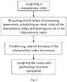
- Fig. 1 is a flowchart of a method for calculating processing parameters for residual stress control by parameter inversion according to preferred embodiments of the present invention. As shown in Fig. 1 , this method will be described below in conjunction with the example of residual stresses in the orthogonal cutting processing.
- a characteristic index of a distribution curve of residual stresses in the processed surface layer of the workpiece is determined.
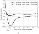
- Fig. 2 is a distribution graph of residual stresses at different depths in the surface layer and a schematic diagram of a curve characteristic index Drs according to the preferred embodiments of the present invention. As shown in Fig. 2 , in this example, only the maximum residual compressive stress depth Drs in the characteristic indexes of the residual stress distribution curve in the x direction is studied.
- reference values of the characteristic index of the residual stress distribution curve and processing parameters associated with it are set.
- processing parameters affecting Drs include the cutting speed V and the feed rate t c .
- H ( V 0 ,t c 0 ) is calculated by a residual stress analytical model for the orthogonal cutting processing as a reference value of Drs .
- the material assumed for the model is nickel-aluminum bronze alloy with elemental composition shown in Table 1, and other input variables in the model are shown in Table 2 and Table 3.
- Fig. 3 is a distribution graph of residual stresses at different cutting speeds according to the preferred embodiments of the present invention
- Fig. 4 is a distribution graph of residual stresses at different feed rates according to the preferred embodiments of the present invention
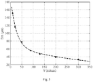
- Fig. 5 is a distribution graph of the characteristic index over the cutting speed according to the preferred embodiments of the present invention
- Fig. 6 is a distribution graph of the characteristic index over the feed rate according to the preferred embodiments of the present invention. Drs in the residual stress curve is extracted, and the fitted curves for Drs to the cutting rate and the feed rate are respectively shown in Fig. 5 and Fig.
- known conditions need to be added into the system of linear equations so that the number of equations is equal to the number of parameters.
- the additional known conditions are: (I) a specific value of the characteristic index of the required residual stress distribution curve, and (II) allocation of the specific value to different processing parameters.
- the additional known conditions must be such that the number of the above equations is equal to the number of parameters.
- Fig. 7 is a graph of Drs ( V ) and Drs ( t c ) of the residual stress over C 1 according to the preferred embodiments of the present invention. As shown in Fig.
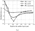
- the comparison of the residual stress curve calculated by plugging processing parameters into the residual stress analytical model and the residual stress curve experimentally measured according to the method provided in the present invention is shown in Fig. 11 . It can be seen that the characteristic indexes Drs of the calculated and experimentally measured residual stress curves are substantially in the vicinity of the desired value of 100 ⁇ m , indicating that the proposed residual stress control method has a certain effect.
- the method of the present invention can be applicable to residual stress control of other processing methods such as forging, welding, laser processing, wire cutting, grinding, drilling, turning, milling, boring, shot peening and heat treatment.
Landscapes
- Engineering & Computer Science (AREA)
- Physics & Mathematics (AREA)
- Theoretical Computer Science (AREA)
- General Physics & Mathematics (AREA)
- Geometry (AREA)
- General Engineering & Computer Science (AREA)
- Evolutionary Computation (AREA)
- Mathematical Optimization (AREA)
- Data Mining & Analysis (AREA)
- Pure & Applied Mathematics (AREA)
- Mathematical Analysis (AREA)
- Computational Mathematics (AREA)
- Artificial Intelligence (AREA)
- Computational Linguistics (AREA)
- Computer Hardware Design (AREA)
- Computing Systems (AREA)
- Mathematical Physics (AREA)
- Software Systems (AREA)
- Automatic Control Of Machine Tools (AREA)
- Turning (AREA)
- Numerical Control (AREA)
Abstract
Description
- The present invention belongs to the field of processing residual stress, and more particularly relates to a method for calculating processing parameters for residual stress control by parameter inversion.
- The residual stress distribution of the processed surface layer of the workpiece has a significant influence on the anti-corrosion and anti-fatigue life of the part. The surface residual tensile stress can easily induce corrosion fatigue crack propagation, thereby reducing the service life of the part; and the surface residual compressive stress is beneficial to mitigation of the corrosion fatigue crack propagation, thereby prolonging the service life of the part. When the processing step is the last step, the residual stress distribution in the processed surface layer has a direct impact on the service life of the part, and the processing residual stress distribution is affected by the processing parameters (including tool parameters). For example, for cutting processing, the residual stress distribution caused by different cutting speeds, feed rates, cutting depths, and tool rake angles are different; and for grinding processing, the residual stress distribution caused by different grinding speeds, feed rates, grinding depths, grinding wheel grain sizes and so on are also different. At present, a large number of literatures have studied the effect of different processing parameters on the residual stress distribution from theoretical modeling and experimental measurements, and to a certain extent, prediction of the residual stress distribution is achieved by the use of processing parameters and material properties.
- With a certain residual stress distribution, the anti-corrosion and anti-fatigue life of the workpiece can be estimated through experiments, so that it can be judged which kind of residual stress distribution is most beneficial to the anti-corrosion and anti-fatigue life. However, it has not yet been reported how to achieve this residual stress distribution which is most beneficial to the anti-corrosion and anti-fatigue life though processing. Theoretically, a specific combination of processing parameters can only give a specific residual stress distribution, but a specific residual stress distribution can correspond to countless combinations of processing parameters. How to solve such kind of "one-to-many" mapping relationship from residual stress to processing parameters is the key problem in achieving the required residual stress distribution by processing, and achievement of the required residual stress by processing is called control of the processing residual stress. In fact, in order to increase the residual compressive stress, special process methods such as shot peening and heat treatment can be used. However, these processing methods can only qualitatively control the residual stress. When these processing methods are actually adopted, relevant processing parameters are also involved, and it still has to be faced with how to set the processing parameters to quantitatively control the residual stress and obtain the required residual stress distribution. At present, the method of controlling the residual stress through processing mainly includes a test method in which a set of processing parameters are first set according to experience, then the set of processing parameters are used for trial processing, and the residual stress distribution is measured after the processing to determine whether it meets the demand; if the demand is not met, the processing parameters are regulated and trial processing is performed again, so that the cycle repeats until the required residual stress distribution is obtained. This test method requires a lot of human, material and financial resources, and when the workpiece material changes, the test method needs to be used again to find suitable processing parameters, which further increases the cost for residual stress control.
- In view of the above-described problems, the present invention provides a method for calculating processing parameters for residual stress control by parameter inversion, in which parameters that affect the residual stress are calculated by a system of inversion equations so that the residual stress after processing reaches a preset value, thereby solving the technical problem of quantitative control of the residual stress.
- In order to achieve the above objective, according to an aspect of the present invention, there is provided a method for calculating processing parameters for residual stress control by parameter inversion, comprising:
- (a) for a workpiece to be processed, acquiring a residual stress distribution curve of the processed surface layer, extracting a plurality of characteristic indexes Drs reflecting the residual stress distribution characteristic from the curve and simultaneously acquiring a plurality of processing parameters Ai (i = 1,2,3...n) corresponding to the characteristic indexes, where i is a serial number of the processing parameter and n is the total number of the processing parameters;
- (b) presetting initial values a 10,a 20,...,a i0,...,a n0 of the respective processing parameters Ai , calculating an initial value H(a 10,a 20,...,a i0,...,a n0) of the characteristic indexes according to the initial values of the processing parameters, and respectively drawing curves of the characteristic indexes Drs over the respective processing parameters Ai to obtain respective fitted curves Drs(Ai ) simultaneously;
- (c) by combining the initial values and the fitted curves of the characteristic indexes obtained in the step (b), establishing the following relation formulas (i), (ii) and (iii) to calculate respective characteristic index increments ΔDrsA
i and the total characteristic index increment ΔDrs, where i is an arbitrary integer and n is the total number of the processing parameters,


- (d) assigning values to the characteristic indexes Drs and the characteristic index increments ΔDrsA
i corresponding to the required residual stress and performing inversion calculation in combination with the relation formulas in the step (c) so as to obtain values of the processing parameters Ai corresponding to the required residual stress. - Preferably, the characteristic indexes include the maximum surface residual stress, the maximum residual compressive stress depth in the surface layer or the depth of the surface tensile stress layer.
- Preferably, in the step (b), the processing parameters include cutting speed, feed rate, cutting depth, tool edge radius or tool rake angle.
- Preferably, in the step (b), the initial value H(a 10,a 20,...,a i0,...,a n0) of the characteristic indexes is calculated by a residual stress analytical model or experimentally measured.
- Preferably, in the step (b), the drawn curves of the characteristic indexes over the respective processing parameters Ai are obtained by a processing residual stress theoretical model or experimental measurements.
- Preferably, in the step (d), the inversion calculation is performed according to the following steps: first, assigning values to the characteristic indexes Drs and the characteristic index increments ΔDrsA
i corresponding to the required residual stress, then establishing the following system of inversion equations by combining the relation formulas (1), (2) and (3); and finally, calculating values of the respective processing parameters Ai by the system of inversion equations, where C 0 and Ci are constants which are preset based on empirical values,
- In general, compared with the prior art, the present invention has the following beneficial effects:
- 1. the present invention provides parameters affecting the residual stress, which are calculated by a system of inversion equations, so that the residual stress after processing reaches a preset value, the mapping limitation only from the processing parameters to the residual stress is broken through, and thus the quantitative control of the residual stress is achieved;
- 2. the present invention forms a system of equations by adopting linear inversion equations, which has simple structure, simple calculation process and short calculation time and clearly and intuitively shows the relationship among various parameters and variables;
- 3. the method for calculating processing parameters for residual stress control provided in the present invention has wide range of application, and is applicable to processing methods such as forging, welding, laser processing, wire cutting, grinding, drilling, turning, boring, milling, shot peening and heat treatment; and
- 4. the present invention realizes quantitative control of the processing residual stress by calculating values of processing parameters affecting the residual stress, and the algorithm has simple operation, thereby reducing the number of tests and lowering the production cost, and improves the processing residual stress distribution of the workpiece, thereby improving the anti-fatigue life of the components.
-
-
Fig. 1 is a flowchart of a method for calculating processing parameters for residual stress control by parameter inversion according to preferred embodiments of the present invention. -
Fig. 2 is a distribution graph of residual stresses at different depths in the surface layer and a schematic diagram of a curve characteristic index Drs according to the preferred embodiments of the present invention. -
Fig. 3 is a distribution graph of residual stresses at different cutting speeds according to the preferred embodiments of the present invention. -
Fig. 4 is a distribution graph of residual stresses at different feed rates according to the preferred embodiments of the present invention. -
Fig. 5 is a distribution graph of the characteristic index over the cutting speed according to the preferred embodiments of the present invention. -
Fig. 6 is a distribution graph of the characteristic index over the feed rate according to the preferred embodiments of the present invention. -
Fig. 7 is a graph of Drs(V) and Drs(tc ) of the residual stress over C 1 according to the preferred embodiments of the present invention. -
Fig. 8 is a comparison diagram of a residual stress curve calculated at tc = 0.207mm and V = 60m / min according to the preferred embodiments of the present invention and a residual stress curve experimentally measured according to the method provided in the present invention. -
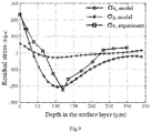
Fig. 9 is a comparison diagram of a residual stress curve calculated at tc = 0.11mm and V = 29.42m / min according to the preferred embodiments of the present invention and a residual stress curve experimentally measured according to the method provided in the present invention. -
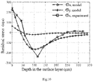
Fig. 10 is a comparison diagram of a residual stress curve calculated at tc = 0.172mm and V = 36.3m / min according to the preferred embodiments of the present invention and a residual stress curve experimentally measured according to the method provided in the present invention. -
Fig. 11 is a comparison diagram of a residual stress curve calculated at tc = 0.19mm and V = 40.7m / min according to the preferred embodiments of the present invention and a residual stress curve experimentally measured according to the method provided in the present invention. - For clear understanding of the objectives, features and advantages of the present invention, detailed description of the present invention will be given below in conjunction with accompanying drawings and specific embodiments. It should be noted that the embodiments described herein are only meant to explain the present invention, and not to limit the scope of the present invention.
-
Fig. 1 is a flowchart of a method for calculating processing parameters for residual stress control by parameter inversion according to preferred embodiments of the present invention. As shown inFig. 1 , this method will be described below in conjunction with the example of residual stresses in the orthogonal cutting processing.
(a) a characteristic index of a distribution curve of residual stresses in the processed surface layer of the workpiece is determined.Fig. 2 is a distribution graph of residual stresses at different depths in the surface layer and a schematic diagram of a curve characteristic index Drs according to the preferred embodiments of the present invention. As shown inFig. 2 , in this example, only the maximum residual compressive stress depth Drs in the characteristic indexes of the residual stress distribution curve in the x direction is studied.
(b) reference values of the characteristic index of the residual stress distribution curve and processing parameters associated with it are set. For the cutting processing, processing parameters affecting Drs include the cutting speed V and the feed rate tc.
In a case of set reference values V 0 = 60m / min and t c0 = 0.11mm / r, H(V 0 ,t c0) is calculated by a residual stress analytical model for the orthogonal cutting processing as a reference value of Drs . Noted that the material assumed for the model is nickel-aluminum bronze alloy with elemental composition shown in Table 1, and other input variables in the model are shown in Table 2 and Table 3.Table 1 chemical composition of the nickel-aluminum bronze alloy Element Copper Aluminum Ferrum Nickel Manganese Carbon Symbol Cu Al Fe Ni Mn C Mass percent (%) 77-82 8.5-10.0 2.0-6.0 3.0-6.0 0.8-2.5 ≤0.10 Table 2 physical properties of the nickel-aluminum bronze alloy Elasticity modulus E Yield stress σs Specific heat capacity c Poisson's ratio Density ρ0 linear expansion coefficient α0 Melting point 110 (Gpa) 300 (Mpa) 419 (J/(kg*°C)) 0.327 7280 (kg/m3) 12∗10-6 (/°C) 1060 (°C) Table 3 values of other input variables in the residual stress analytical model Friction coefficient of tool flank µ Cutting width w (mm) Shear angle ϕ(°) Thermal conductivity λ (W/(mm°C)) 0.22 5 22 0.03 Length of wear land of tool flank VB (mm) Rake angle α(°) Cutting force in the cutting speed direction Fc (N) Cutting force in the feed direction Ft (N) 0.04 17 1000 300
A curve of residual stress distribution in the surface layer under the independent action of each processing parameter (such as cutting speed, feed rate, cutting depth and tool rake angle) is obtained by the processing residual stress theoretical model or experimental measurement, and a curve of the characteristic index over each processing parameter is fitted.Fig. 3 is a distribution graph of residual stresses at different cutting speeds according to the preferred embodiments of the present invention, andFig. 4 is a distribution graph of residual stresses at different feed rates according to the preferred embodiments of the present invention.
Fig. 5 is a distribution graph of the characteristic index over the cutting speed according to the preferred embodiments of the present invention, andFig. 6 is a distribution graph of the characteristic index over the feed rate according to the preferred embodiments of the present invention. Drs in the residual stress curve is extracted, and the fitted curves for Drs to the cutting rate and the feed rate are respectively shown inFig. 5 andFig. 6 , and their fitting functions are respectively Drs (V) = 128e -0.04012∗V + 65.15e -0.002407∗V and Drs (tc) = 74.3e 1.945∗tc - 50.43e -7.369∗tc .
(c) the effects of multiple processing parameters on the characteristic index of the residual stress curve are regarded to be linearly superimposed, and by taking the superimposed characteristic indexes of the residual stress curves and their increments as a parameter matrix M, establishing a system of linear equations expressing the relation among the characteristic indexes according to linear inversion equations: G·M = F, where G represents a coefficient matrix, and F represents observation data (i.e., a constant term). Taking the cutting residual stress as an example, increments of Drs resulting from the cutting speed and the feed rate are respectively ΔDrsV = Drs(V) - H(V 0, t c0) and ΔDrstc = Drs(tc ) - H(V 0, t c0), and then the total increment (linear superposition) of Drs resulting from the cutting speed and the feed rate is ΔDrs = ΔDrsV + ΔDrstc , where ΔDrs can also be expressed as ΔDrs = Drs - H(V 0, t c0). Except the variable H(V 0, t c0), other six variables ΔDrsV , ΔDrstc, Drs(V), Drs(tc), ΔDrs and Drs in the above four formulas are regarded as parameters, and then the four formulas can be combined into a system of linear equations:
The above system of linear equations is expressed in a form of a matrix G·M = F as follow:
(d) since the number of equations in the system of linear equations (2) obtained in the previous step is 4 and the number of parameters is 6, the system of linear equations has infinitely many solutions. In order to obtain a unique solution, known conditions need to be added into the system of linear equations so that the number of equations is equal to the number of parameters. The additional known conditions are: (I) a specific value of the characteristic index of the required residual stress distribution curve, and (II) allocation of the specific value to different processing parameters. The additional known conditions must be such that the number of the above equations is equal to the number of parameters. Taking the cutting residual stress as an example, it is required that the maximum residual compressive stress depth in the surface layer after machining is Drs = C 0 ; since Drs can be affected by the cutting speed and the feed rate at the same time, the increment of Drs resulting from the feed rate can be set as ΔDrstc = C 1 (or the increment of Drs resulting from the cutting speed can be set as ΔDrsV = C 2). Thus, two known conditions are added into the system of linear equations (2):
- The above system of linear equations is expressed in a form of a matrix G·M = F as follow:

- The system of linear equations (4) has a unique solution and can be solved as follows:

- It can be seen that if C 1 is regarded as a variable and Drs(V) and Drs(tc ) are regarded as functions, their relationship can be represented by straight lines.
Fig. 7 is a graph of Drs(V) and Drs(tc ) of the residual stress over C 1 according to the preferred embodiments of the present invention. As shown inFig. 7 , the dash and dot line perpendicular to the C 1 axis respectively intersects function graph lines of Drs(V) and Drs(tc ) at points A and B, indicating that when C 0, C 1 and H(V 0 ,t c0) are determined, values of Drs(V) and Drs(tc ) can be uniquely determined. Thus, according to the cutting conditions in step (2), it can be calculated that H (V 0, t c0) = 79µm, and for the required Drs = C 0, it is set that C 0 = 100µm. There are several situations in determination of C 1: - a) if ΔDrs is individually allocated to ΔDrstc , ΔDrstc = C 1 = 21µm, ΔDrsV = 0µm ;
- b) if ΔDrs is individually allocated to ΔDrsV , ΔDrstc = C 1 = 0µm, ΔDrsV = 21µm;
- c) if ΔDrs is equally allocated to ΔDrstc and ΔDrsV , ΔDrstc = C 1 = 10.5µm, ΔDrsV = 10.5µm ; and
- d) if ΔDrs is randomly allocated to ΔDrstc and ΔDrsV , for example, ΔDrstc = C 1 = 16µm, then ΔDrsV = 5µm.
- The assignments of C 1 in these four situations will result in the following results of Drs(V) and Drs(tc ) in four situations:
- a) Drs(tc ) = 100µm, Drs(V) = 79µm ;
- b) Drs(tc ) = 79µm, Drs(V) = 100µm ;
- c) Drs(tc ) = 89.5µm, Drs(V) = 89.5µm; and
- d) Drs(tc ) = 95µm, Drs(V) = 84µm.
- Finally, values of tc and V in the four situations are calculated by the fitted formulas Drs(V) = 128e -0.04012∗V + 65.15e -0.002407∗V and Drs(tc ) = 74.3e 1.945∗tc - 50.43e -7.369∗tc in the step (3):
- a) tc = 0.207mm, V = 60m / min ;
- b) tc = 0.11mm, V = 29.42m / min ;
- c) tc = 0.172mm, V = 36.3m / min ; and
- d) tc = 0.19mm, V = 40.7m / min.
- This is the final result obtained by using the set residual stress to calculate the processing parameters. In theory, the use of these calculated processing parameters during processing can achieve required processing residual stress distribution.
Fig. 8 is a comparison diagram of a residual stress curve calculated at tc = 0.207mm and V = 60m / min according to the preferred embodiments of the present invention and a residual stress curve experimentally measured according to the method provided in the present invention;Fig. 9 is a comparison diagram of a residual stress curve calculated at tc = 0.11mm and V = 29.42m / min according to the preferred embodiments of the present invention and a residual stress curve experimentally measured according to the method provided in the present invention;Fig. 10 is a comparison diagram of a residual stress curve calculated at tc = 0.172mm and V = 36.3m / min according to the preferred embodiments of the present invention and a residual stress curve experimentally measured according to the method provided in the present invention; andFig. 11 is a comparison diagram of a residual stress curve calculated at tc = 0.19mm and V = 40.7m / min according to the preferred embodiments of the present invention and a residual stress curve experimentally measured according to the method provided in the present invention. The comparison of the residual stress curve calculated by plugging processing parameters into the residual stress analytical model and the residual stress curve experimentally measured according to the method provided in the present invention is shown inFig. 11 . It can be seen that the characteristic indexes Drs of the calculated and experimentally measured residual stress curves are substantially in the vicinity of the desired value of 100µm, indicating that the proposed residual stress control method has a certain effect. - The above is just described by taking the orthogonal cutting processing as an example, and the method of the present invention can be applicable to residual stress control of other processing methods such as forging, welding, laser processing, wire cutting, grinding, drilling, turning, milling, boring, shot peening and heat treatment.
- While particular embodiments of the present invention have been shown and described, it will be obvious to those skilled in the art that changes and modifications may be made without departing from the spirit and scope of the present invention.
Claims (6)
- A method for calculating processing parameters for residual stress control by parameter inversion, comprising:(a) for a workpiece to be processed, acquiring a residual stress distribution curve of a processed surface layer, extracting a plurality of characteristic indexes Drs reflecting the residual stress distribution characteristic from the curve and simultaneously acquiring a plurality of processing parameters Ai (i = 1,2,3...n) corresponding to the characteristic indexes, where i is a serial number of the processing parameter and n is the total number of the processing parameters;(b) presetting initial values a 10 ,a 20,...,a i0,...,a n0 of the respective processing parameters Ai , calculating an initial value H(a 10,a 20,...,a i0,...,a n0) of the characteristic index according to the initial values of the processing parameters, and respectively drawing curves of the characteristic indexes Drs over the respective processing parameters Ai to obtain respective fitted curves Drs(Ai ) simultaneously;(c) by combining the initial values and the fitted curves of the characteristic index obtained in the step (b), establishing the following relation formulas (i), (ii) and (iii) to calculate respective characteristic index increments ΔDrsA
i and the total characteristic index increment ΔDrs, where i is an arbitrary integer and n is the total number of the processing parameters,

 (d) assigning values to the characteristic indexes Drs and the characteristic index increments ΔDrsA
i corresponding to the required residual stress and performing inversion calculation in combination with the relation formulas in the step (c) so as to obtain values of the processing parameters Ai corresponding to the required residual stress. - The method as claimed in claim 1, wherein the characteristic indexes include the maximum surface residual stress, the maximum residual compressive stress depth in the surface layer or the depth of the surface tensile stress layer.
- The method as claimed in claim 1 or 2, wherein in the step (b), the processing parameters include cutting speed, feed rate, cutting depth, tool edge radius or tool rake angle.
- The method as claimed in any one of claims 1-3, wherein the initial value H(a 10 ,a 20, ....a i0,...,a n0) of the characteristic indexes is calculated by a residual stress analytical model or experimentally measured.
- The method as claimed in any one of claims 1-4, wherein in the step (b), the drawn curves of the characteristic indexes over the respective processing parameters Ai are obtained by a processing residual stress theoretical model or experimental measurements.
- The method as claimed in any one of claims 1-5, wherein in the step (d), the inversion calculation is performed according to the following steps: first, assigning values to the characteristic indexes Drs and the characteristic index increments ΔDrsA
i corresponding to the required residual stress, then establishing the following system of inversion equations by combining the relation formulas (1), (2) and (3); and finally, calculating values of the respective processing parameters Ai by the system of inversion equations, where C 0 and Ci are constants which are preset based on empirical values,
Applications Claiming Priority (2)
| Application Number | Priority Date | Filing Date | Title |
|---|---|---|---|
| CN201710504692.7A CN107273630B (en) | 2017-06-28 | 2017-06-28 | Method for regulating and controlling residual stress processing parameters through parameter inversion calculation |
| PCT/CN2017/093256 WO2019000506A1 (en) | 2017-06-28 | 2017-07-18 | Method for calculating regulation and control residual stress processing parameters by means of parameter inversion |
Publications (3)
| Publication Number | Publication Date |
|---|---|
| EP3647971A1 true EP3647971A1 (en) | 2020-05-06 |
| EP3647971A4 EP3647971A4 (en) | 2020-10-14 |
| EP3647971B1 EP3647971B1 (en) | 2021-09-08 |
Family
ID=60070289
Family Applications (1)
| Application Number | Title | Priority Date | Filing Date |
|---|---|---|---|
| EP17898330.0A Active EP3647971B1 (en) | 2017-06-28 | 2017-07-18 | Method for calculating regulation and control of residual stress processing parameters by means of parameter inversion |
Country Status (6)
| Country | Link |
|---|---|
| US (1) | US11501031B2 (en) |
| EP (1) | EP3647971B1 (en) |
| JP (1) | JP2019526082A (en) |
| CN (1) | CN107273630B (en) |
| DK (1) | DK3647971T3 (en) |
| WO (1) | WO2019000506A1 (en) |
Families Citing this family (15)
| Publication number | Priority date | Publication date | Assignee | Title |
|---|---|---|---|---|
| CN109870257B (en) * | 2017-12-04 | 2020-12-18 | 有研工程技术研究院有限公司 | Method for predicting distribution of quenching residual stress in thickness direction of plate |
| JP6867329B2 (en) * | 2018-04-25 | 2021-04-28 | 株式会社神戸製鋼所 | Residual stress calculation method |
| CN113158351B (en) * | 2020-01-22 | 2024-08-27 | 上海飞机制造有限公司 | A method, device, equipment and storage medium for constructing a finite element simulation model |
| CN112100888B (en) * | 2020-09-07 | 2024-04-30 | 南京航空航天大学 | A method for predicting residual stress in blade tenon grinding during slow-feed deep cutting |
| CN113239461B (en) * | 2021-05-14 | 2023-09-15 | 扬州大学 | A deformation control method for complex thin-walled parts with asymmetric structure |
| CN114021401A (en) * | 2021-09-24 | 2022-02-08 | 国营芜湖机械厂 | Method for predicting gradient distribution of residual stress field of cutting surface |
| CN114936393B (en) * | 2022-03-29 | 2024-06-28 | 中铁第四勘察设计院集团有限公司 | Method and device for determining optimal beam height of cable-stayed bridge and electronic equipment |
| CN114939772B (en) * | 2022-04-20 | 2023-12-19 | 湖南星途航空航天器制造有限公司 | Force adaptability method for machining thin-wall arc-shaped piece |
| CN114707387B (en) * | 2022-04-25 | 2025-03-18 | 有研工程技术研究院有限公司 | Milling parameter optimization method for aluminum alloy by pre-adding initial residual stress for simulation |
| CN114850964B (en) * | 2022-04-27 | 2023-04-07 | 清华大学 | Method, device and equipment for processing three-dimensional structure of metal surface and storage medium |
| CN116562070B (en) * | 2023-03-15 | 2023-11-24 | 青岛理工大学 | A method, device, equipment and medium for determining the priority of shield pile cutting parameters |
| CN117195669B (en) * | 2023-09-07 | 2025-03-18 | 重庆大学 | Grinding wheel grinding ratio measurement method based on grinding wheel multi-information fusion model |
| CN118190215A (en) * | 2024-03-22 | 2024-06-14 | 成都国营锦江机器厂 | Cosine function-based processing residual stress characteristic parameter characterization method |
| CN118762784B (en) * | 2024-09-02 | 2025-01-24 | 寰采星科技(宁波)有限公司 | Foil manufacturing process parameter screening method and system |
| CN119296694B (en) * | 2024-09-24 | 2026-01-13 | 中建安装集团有限公司 | A method, medium, and system for determining welding parameters of TP321H steel. |
Family Cites Families (15)
| Publication number | Priority date | Publication date | Assignee | Title |
|---|---|---|---|---|
| US5878496A (en) * | 1996-04-09 | 1999-03-09 | Purdue Research Foundation | Method of manufacturing a component |
| DE10000845B4 (en) * | 2000-01-12 | 2006-07-27 | Bwg Bergwerk- Und Walzwerk-Maschinenbau Gmbh | Method and device for non-contact flatness measurement of metal strips made of ferromagnetic materials |
| US7906745B2 (en) * | 2003-12-10 | 2011-03-15 | Lsp Technologies, Inc. | Bend bar quality control method for laser shock peening |
| US8629368B2 (en) * | 2006-01-30 | 2014-01-14 | Dm3D Technology, Llc | High-speed, ultra precision manufacturing station that combines direct metal deposition and EDM |
| JP4884840B2 (en) * | 2006-05-25 | 2012-02-29 | ユニプレス株式会社 | How to create press mold correction shape data |
| WO2014028599A1 (en) * | 2012-08-14 | 2014-02-20 | Guo Yuebin | A biodegradable medical device having an adjustable degradation rate and methods of making the same |
| US20150286757A1 (en) * | 2014-04-04 | 2015-10-08 | Shi-Chune Yao | Method for Efficiently Predicting the Quality of Additively Manufactured Metal Products |
| US9963941B2 (en) * | 2015-06-22 | 2018-05-08 | Baker Hughes Incorporated | Methods of forming cutting elements and earth-boring tools carrying such cutting elements |
| WO2017177198A1 (en) * | 2016-04-07 | 2017-10-12 | The Texas A&M University System | Polymer composites with highly tunable thermal and mechanical properties and methods of manufacture |
| CN105975708A (en) * | 2016-05-16 | 2016-09-28 | 中国计量大学 | Steel tube welding parameter optimization method based on numerical simulation and data analysis |
| CN106041679A (en) * | 2016-06-17 | 2016-10-26 | 中航工业哈尔滨轴承有限公司 | Grinding method with residual stress controlled |
| CN106529053B (en) * | 2016-11-16 | 2018-03-16 | 西北工业大学 | A kind of Forecasting Methodology of titanium alloy milling residual stress field |
| CN106891204B (en) * | 2017-01-09 | 2018-11-13 | 西北工业大学 | A kind of preparation method in the antifatigue grinding process parameters domain of superalloy components |
| CN106872303B (en) * | 2017-01-09 | 2019-03-05 | 西北工业大学 | A method for obtaining the process parameter domain of anti-fatigue grinding of ultra-high-strength steel components |
| CN106897484B (en) * | 2017-01-09 | 2020-02-07 | 西北工业大学 | Method for obtaining high-efficiency low-stress grinding technological parameters of high-temperature alloy |
-
2017
- 2017-06-28 CN CN201710504692.7A patent/CN107273630B/en active Active
- 2017-07-18 JP JP2018534972A patent/JP2019526082A/en active Pending
- 2017-07-18 EP EP17898330.0A patent/EP3647971B1/en active Active
- 2017-07-18 DK DK17898330.0T patent/DK3647971T3/en active
- 2017-07-18 WO PCT/CN2017/093256 patent/WO2019000506A1/en not_active Ceased
-
2019
- 2019-04-02 US US16/373,606 patent/US11501031B2/en active Active
Also Published As
| Publication number | Publication date |
|---|---|
| EP3647971B1 (en) | 2021-09-08 |
| WO2019000506A1 (en) | 2019-01-03 |
| EP3647971A4 (en) | 2020-10-14 |
| CN107273630A (en) | 2017-10-20 |
| JP2019526082A (en) | 2019-09-12 |
| US20190228129A1 (en) | 2019-07-25 |
| DK3647971T3 (en) | 2021-12-06 |
| CN107273630B (en) | 2020-05-19 |
| US11501031B2 (en) | 2022-11-15 |
Similar Documents
| Publication | Publication Date | Title |
|---|---|---|
| EP3647971B1 (en) | Method for calculating regulation and control of residual stress processing parameters by means of parameter inversion | |
| Das et al. | Study of surface roughness and flank wear in hard turning of AISI 4140 steel with coated ceramic inserts | |
| CN106503350B (en) | A kind of design method of spiral bevel gear long-life transmission fatigue reliability | |
| Senthilkumar et al. | Study of electrochemical machining characteristics of Al/SiCp composites | |
| EP3312298B1 (en) | Steel pipe for fuel spray pipe and manufacturing method therefor | |
| Gaitonde et al. | Multiresponse optimization in wire electric discharge machining (WEDM) of HCHCr steel by integrating response surface methodology (RSM) with differential evolution (DE) | |
| KR101833191B1 (en) | Surface grain refining hot-shearing method and product of surface grain refining hot-shearing | |
| Scholtes | Residual stresses introduced by machining | |
| Bhushan | Multi-response optimization of parameters during turning of AA7075/SiC composite for minimum surface roughness and maximum tool life | |
| Bayraktar et al. | Investigation of the effect on surface roughness of cryogenic process applied to cutting tool | |
| JP6314648B2 (en) | Surface hardened component and method for manufacturing surface hardened component | |
| Mohite et al. | An investigation of effect of dressing parameters for minimum surface roughness using CNC cylindrical grinding machine | |
| da Silva et al. | Enhancing the fatigue strength of AISI 4140 steel through in-situ urea-assisted EDM nitriding | |
| Khundrakpam et al. | Investigation and modeling of silicon powder mixed EDM using response surface method | |
| Sanchez Egea et al. | Sliding abrasive wear when combining WEDM conditions and polishing treatment on H13 disks over 1045 carbon steel pins | |
| Prabhu et al. | Modeling the machining parameters of AISI D2 tool steel material with multi wall carbon nano tube in electrical discharge machining process using response surface methodology | |
| Lopes et al. | Influence of machining parameters on fatigue endurance limit of AISI 4140 steel | |
| Babu et al. | Numerical investigation of key stamping process parameters influencing tool life and wear | |
| Lawal et al. | Effect of HSS and tungsten carbide tools on surface roughness of aluminium alloy during turning operation | |
| Sabberwal et al. | The effect of material and geometry on the wear characteristics of cutting tools during face milling | |
| Arslan et al. | An investigation of the hole diameter and circulirty on the stainless steel sheet perforated via by deep cryogenically treated cold work tool steel punches | |
| Chidambaram et al. | Modelling and Analysis of Tool Wear on a Cryogenically Treated CNMG120408SMRH13A Insert in the Turning of AISI4340 Steel Using Response Surface Methodology | |
| Misra et al. | Effects of electrolyte composition and temperature on precision finishing of spur gears by pulse electrochemical honing (PECH) | |
| Easton et al. | Residual stress in case hardened steel gears | |
| Ramesh et al. | Optimization of process parameter levels during conventional milling of beryllium copper alloy using end mill |
Legal Events
| Date | Code | Title | Description |
|---|---|---|---|
| STAA | Information on the status of an ep patent application or granted ep patent |
Free format text: STATUS: UNKNOWN |
|
| STAA | Information on the status of an ep patent application or granted ep patent |
Free format text: STATUS: THE INTERNATIONAL PUBLICATION HAS BEEN MADE |
|
| PUAI | Public reference made under article 153(3) epc to a published international application that has entered the european phase |
Free format text: ORIGINAL CODE: 0009012 |
|
| STAA | Information on the status of an ep patent application or granted ep patent |
Free format text: STATUS: REQUEST FOR EXAMINATION WAS MADE |
|
| 17P | Request for examination filed |
Effective date: 20180904 |
|
| AK | Designated contracting states |
Kind code of ref document: A1 Designated state(s): AL AT BE BG CH CY CZ DE DK EE ES FI FR GB GR HR HU IE IS IT LI LT LU LV MC MK MT NL NO PL PT RO RS SE SI SK SM TR |
|
| AX | Request for extension of the european patent |
Extension state: BA ME |
|
| R17P | Request for examination filed (corrected) |
Effective date: 20180904 |
|
| REG | Reference to a national code |
Ref country code: DE Ref legal event code: R079 Ref document number: 602017045879 Country of ref document: DE Free format text: PREVIOUS MAIN CLASS: G06F0017500000 Ipc: G06F0030170000 |
|
| DAV | Request for validation of the european patent (deleted) | ||
| DAX | Request for extension of the european patent (deleted) | ||
| A4 | Supplementary search report drawn up and despatched |
Effective date: 20200911 |
|
| RIC1 | Information provided on ipc code assigned before grant |
Ipc: G06N 5/04 20060101ALI20200907BHEP Ipc: G06F 119/18 20200101ALI20200907BHEP Ipc: G06F 30/17 20200101AFI20200907BHEP Ipc: G01L 5/00 20060101ALI20200907BHEP |
|
| GRAP | Despatch of communication of intention to grant a patent |
Free format text: ORIGINAL CODE: EPIDOSNIGR1 |
|
| STAA | Information on the status of an ep patent application or granted ep patent |
Free format text: STATUS: GRANT OF PATENT IS INTENDED |
|
| INTG | Intention to grant announced |
Effective date: 20210330 |
|
| GRAS | Grant fee paid |
Free format text: ORIGINAL CODE: EPIDOSNIGR3 |
|
| GRAA | (expected) grant |
Free format text: ORIGINAL CODE: 0009210 |
|
| STAA | Information on the status of an ep patent application or granted ep patent |
Free format text: STATUS: THE PATENT HAS BEEN GRANTED |
|
| AK | Designated contracting states |
Kind code of ref document: B1 Designated state(s): AL AT BE BG CH CY CZ DE DK EE ES FI FR GB GR HR HU IE IS IT LI LT LU LV MC MK MT NL NO PL PT RO RS SE SI SK SM TR |
|
| REG | Reference to a national code |
Ref country code: GB Ref legal event code: FG4D |
|
| REG | Reference to a national code |
Ref country code: CH Ref legal event code: EP Ref country code: AT Ref legal event code: REF Ref document number: 1429248 Country of ref document: AT Kind code of ref document: T Effective date: 20210915 |
|
| REG | Reference to a national code |
Ref country code: DE Ref legal event code: R096 Ref document number: 602017045879 Country of ref document: DE |
|
| REG | Reference to a national code |
Ref country code: IE Ref legal event code: FG4D |
|
| REG | Reference to a national code |
Ref country code: SE Ref legal event code: TRGR |
|
| REG | Reference to a national code |
Ref country code: DK Ref legal event code: T3 Effective date: 20211202 |
|
| REG | Reference to a national code |
Ref country code: LT Ref legal event code: MG9D |
|
| REG | Reference to a national code |
Ref country code: NO Ref legal event code: T2 Effective date: 20210908 |
|
| REG | Reference to a national code |
Ref country code: NL Ref legal event code: FP |
|
| PG25 | Lapsed in a contracting state [announced via postgrant information from national office to epo] |
Ref country code: RS Free format text: LAPSE BECAUSE OF FAILURE TO SUBMIT A TRANSLATION OF THE DESCRIPTION OR TO PAY THE FEE WITHIN THE PRESCRIBED TIME-LIMIT Effective date: 20210908 Ref country code: FI Free format text: LAPSE BECAUSE OF FAILURE TO SUBMIT A TRANSLATION OF THE DESCRIPTION OR TO PAY THE FEE WITHIN THE PRESCRIBED TIME-LIMIT Effective date: 20210908 Ref country code: ES Free format text: LAPSE BECAUSE OF FAILURE TO SUBMIT A TRANSLATION OF THE DESCRIPTION OR TO PAY THE FEE WITHIN THE PRESCRIBED TIME-LIMIT Effective date: 20210908 Ref country code: HR Free format text: LAPSE BECAUSE OF FAILURE TO SUBMIT A TRANSLATION OF THE DESCRIPTION OR TO PAY THE FEE WITHIN THE PRESCRIBED TIME-LIMIT Effective date: 20210908 Ref country code: BG Free format text: LAPSE BECAUSE OF FAILURE TO SUBMIT A TRANSLATION OF THE DESCRIPTION OR TO PAY THE FEE WITHIN THE PRESCRIBED TIME-LIMIT Effective date: 20211208 Ref country code: LT Free format text: LAPSE BECAUSE OF FAILURE TO SUBMIT A TRANSLATION OF THE DESCRIPTION OR TO PAY THE FEE WITHIN THE PRESCRIBED TIME-LIMIT Effective date: 20210908 |
|
| REG | Reference to a national code |
Ref country code: AT Ref legal event code: MK05 Ref document number: 1429248 Country of ref document: AT Kind code of ref document: T Effective date: 20210908 |
|
| PG25 | Lapsed in a contracting state [announced via postgrant information from national office to epo] |
Ref country code: LV Free format text: LAPSE BECAUSE OF FAILURE TO SUBMIT A TRANSLATION OF THE DESCRIPTION OR TO PAY THE FEE WITHIN THE PRESCRIBED TIME-LIMIT Effective date: 20210908 Ref country code: GR Free format text: LAPSE BECAUSE OF FAILURE TO SUBMIT A TRANSLATION OF THE DESCRIPTION OR TO PAY THE FEE WITHIN THE PRESCRIBED TIME-LIMIT Effective date: 20211209 |
|
| PG25 | Lapsed in a contracting state [announced via postgrant information from national office to epo] |
Ref country code: AT Free format text: LAPSE BECAUSE OF FAILURE TO SUBMIT A TRANSLATION OF THE DESCRIPTION OR TO PAY THE FEE WITHIN THE PRESCRIBED TIME-LIMIT Effective date: 20210908 |
|
| PG25 | Lapsed in a contracting state [announced via postgrant information from national office to epo] |
Ref country code: IS Free format text: LAPSE BECAUSE OF FAILURE TO SUBMIT A TRANSLATION OF THE DESCRIPTION OR TO PAY THE FEE WITHIN THE PRESCRIBED TIME-LIMIT Effective date: 20220108 Ref country code: SM Free format text: LAPSE BECAUSE OF FAILURE TO SUBMIT A TRANSLATION OF THE DESCRIPTION OR TO PAY THE FEE WITHIN THE PRESCRIBED TIME-LIMIT Effective date: 20210908 Ref country code: SK Free format text: LAPSE BECAUSE OF FAILURE TO SUBMIT A TRANSLATION OF THE DESCRIPTION OR TO PAY THE FEE WITHIN THE PRESCRIBED TIME-LIMIT Effective date: 20210908 Ref country code: RO Free format text: LAPSE BECAUSE OF FAILURE TO SUBMIT A TRANSLATION OF THE DESCRIPTION OR TO PAY THE FEE WITHIN THE PRESCRIBED TIME-LIMIT Effective date: 20210908 Ref country code: PT Free format text: LAPSE BECAUSE OF FAILURE TO SUBMIT A TRANSLATION OF THE DESCRIPTION OR TO PAY THE FEE WITHIN THE PRESCRIBED TIME-LIMIT Effective date: 20220110 Ref country code: PL Free format text: LAPSE BECAUSE OF FAILURE TO SUBMIT A TRANSLATION OF THE DESCRIPTION OR TO PAY THE FEE WITHIN THE PRESCRIBED TIME-LIMIT Effective date: 20210908 Ref country code: EE Free format text: LAPSE BECAUSE OF FAILURE TO SUBMIT A TRANSLATION OF THE DESCRIPTION OR TO PAY THE FEE WITHIN THE PRESCRIBED TIME-LIMIT Effective date: 20210908 Ref country code: CZ Free format text: LAPSE BECAUSE OF FAILURE TO SUBMIT A TRANSLATION OF THE DESCRIPTION OR TO PAY THE FEE WITHIN THE PRESCRIBED TIME-LIMIT Effective date: 20210908 Ref country code: AL Free format text: LAPSE BECAUSE OF FAILURE TO SUBMIT A TRANSLATION OF THE DESCRIPTION OR TO PAY THE FEE WITHIN THE PRESCRIBED TIME-LIMIT Effective date: 20210908 |
|
| REG | Reference to a national code |
Ref country code: DE Ref legal event code: R097 Ref document number: 602017045879 Country of ref document: DE |
|
| PLBE | No opposition filed within time limit |
Free format text: ORIGINAL CODE: 0009261 |
|
| STAA | Information on the status of an ep patent application or granted ep patent |
Free format text: STATUS: NO OPPOSITION FILED WITHIN TIME LIMIT |
|
| 26N | No opposition filed |
Effective date: 20220609 |
|
| PG25 | Lapsed in a contracting state [announced via postgrant information from national office to epo] |
Ref country code: SI Free format text: LAPSE BECAUSE OF FAILURE TO SUBMIT A TRANSLATION OF THE DESCRIPTION OR TO PAY THE FEE WITHIN THE PRESCRIBED TIME-LIMIT Effective date: 20210908 |
|
| PG25 | Lapsed in a contracting state [announced via postgrant information from national office to epo] |
Ref country code: IT Free format text: LAPSE BECAUSE OF FAILURE TO SUBMIT A TRANSLATION OF THE DESCRIPTION OR TO PAY THE FEE WITHIN THE PRESCRIBED TIME-LIMIT Effective date: 20210908 |
|
| REG | Reference to a national code |
Ref country code: DK Ref legal event code: EBP Effective date: 20220731 |
|
| PG25 | Lapsed in a contracting state [announced via postgrant information from national office to epo] |
Ref country code: MC Free format text: LAPSE BECAUSE OF FAILURE TO SUBMIT A TRANSLATION OF THE DESCRIPTION OR TO PAY THE FEE WITHIN THE PRESCRIBED TIME-LIMIT Effective date: 20210908 |
|
| REG | Reference to a national code |
Ref country code: CH Ref legal event code: PL Ref country code: SE Ref legal event code: EUG |
|
| REG | Reference to a national code |
Ref country code: NL Ref legal event code: MM Effective date: 20220801 |
|
| GBPC | Gb: european patent ceased through non-payment of renewal fee |
Effective date: 20220718 |
|
| REG | Reference to a national code |
Ref country code: BE Ref legal event code: MM Effective date: 20220731 |
|
| PG25 | Lapsed in a contracting state [announced via postgrant information from national office to epo] |
Ref country code: SE Free format text: LAPSE BECAUSE OF NON-PAYMENT OF DUE FEES Effective date: 20220719 Ref country code: LU Free format text: LAPSE BECAUSE OF NON-PAYMENT OF DUE FEES Effective date: 20220718 Ref country code: LI Free format text: LAPSE BECAUSE OF NON-PAYMENT OF DUE FEES Effective date: 20220731 Ref country code: FR Free format text: LAPSE BECAUSE OF NON-PAYMENT OF DUE FEES Effective date: 20220731 Ref country code: CH Free format text: LAPSE BECAUSE OF NON-PAYMENT OF DUE FEES Effective date: 20220731 |
|
| PG25 | Lapsed in a contracting state [announced via postgrant information from national office to epo] |
Ref country code: GB Free format text: LAPSE BECAUSE OF NON-PAYMENT OF DUE FEES Effective date: 20220718 Ref country code: BE Free format text: LAPSE BECAUSE OF NON-PAYMENT OF DUE FEES Effective date: 20220731 |
|
| PG25 | Lapsed in a contracting state [announced via postgrant information from national office to epo] |
Ref country code: NL Free format text: LAPSE BECAUSE OF NON-PAYMENT OF DUE FEES Effective date: 20220801 |
|
| PG25 | Lapsed in a contracting state [announced via postgrant information from national office to epo] |
Ref country code: IE Free format text: LAPSE BECAUSE OF NON-PAYMENT OF DUE FEES Effective date: 20220718 Ref country code: DK Free format text: LAPSE BECAUSE OF NON-PAYMENT OF DUE FEES Effective date: 20220731 |
|
| PG25 | Lapsed in a contracting state [announced via postgrant information from national office to epo] |
Ref country code: HU Free format text: LAPSE BECAUSE OF FAILURE TO SUBMIT A TRANSLATION OF THE DESCRIPTION OR TO PAY THE FEE WITHIN THE PRESCRIBED TIME-LIMIT; INVALID AB INITIO Effective date: 20170718 |
|
| PG25 | Lapsed in a contracting state [announced via postgrant information from national office to epo] |
Ref country code: MK Free format text: LAPSE BECAUSE OF FAILURE TO SUBMIT A TRANSLATION OF THE DESCRIPTION OR TO PAY THE FEE WITHIN THE PRESCRIBED TIME-LIMIT Effective date: 20210908 Ref country code: CY Free format text: LAPSE BECAUSE OF FAILURE TO SUBMIT A TRANSLATION OF THE DESCRIPTION OR TO PAY THE FEE WITHIN THE PRESCRIBED TIME-LIMIT Effective date: 20210908 |
|
| PG25 | Lapsed in a contracting state [announced via postgrant information from national office to epo] |
Ref country code: TR Free format text: LAPSE BECAUSE OF FAILURE TO SUBMIT A TRANSLATION OF THE DESCRIPTION OR TO PAY THE FEE WITHIN THE PRESCRIBED TIME-LIMIT Effective date: 20210908 |
|
| REG | Reference to a national code |
Ref country code: DE Ref legal event code: R082 Ref document number: 602017045879 Country of ref document: DE Representative=s name: STRAUS, ALEXANDER, DIPL.-CHEM.UNIV. DR.PHIL., DE |
|
| PG25 | Lapsed in a contracting state [announced via postgrant information from national office to epo] |
Ref country code: MT Free format text: LAPSE BECAUSE OF FAILURE TO SUBMIT A TRANSLATION OF THE DESCRIPTION OR TO PAY THE FEE WITHIN THE PRESCRIBED TIME-LIMIT Effective date: 20210908 |
|
| PGFP | Annual fee paid to national office [announced via postgrant information from national office to epo] |
Ref country code: DE Payment date: 20240819 Year of fee payment: 8 |
|
| PGFP | Annual fee paid to national office [announced via postgrant information from national office to epo] |
Ref country code: NO Payment date: 20251118 Year of fee payment: 9 |
|
| REG | Reference to a national code |
Ref country code: DE Ref legal event code: R119 Ref document number: 602017045879 Country of ref document: DE |
|
| PG25 | Lapsed in a contracting state [announced via postgrant information from national office to epo] |
Ref country code: DE Free format text: LAPSE BECAUSE OF NON-PAYMENT OF DUE FEES Effective date: 20260203 |