EP3647904A1 - Method and system for device activation - Google Patents
Method and system for device activation Download PDFInfo
- Publication number
- EP3647904A1 EP3647904A1 EP19189664.6A EP19189664A EP3647904A1 EP 3647904 A1 EP3647904 A1 EP 3647904A1 EP 19189664 A EP19189664 A EP 19189664A EP 3647904 A1 EP3647904 A1 EP 3647904A1
- Authority
- EP
- European Patent Office
- Prior art keywords
- movement data
- electronic device
- activation criteria
- power state
- control circuit
- Prior art date
- Legal status (The legal status is an assumption and is not a legal conclusion. Google has not performed a legal analysis and makes no representation as to the accuracy of the status listed.)
- Granted
Links
Images


Classifications
-
- G—PHYSICS
- G06—COMPUTING OR CALCULATING; COUNTING
- G06F—ELECTRIC DIGITAL DATA PROCESSING
- G06F1/00—Details not covered by groups G06F3/00 - G06F13/00 and G06F21/00
- G06F1/26—Power supply means, e.g. regulation thereof
- G06F1/32—Means for saving power
- G06F1/3203—Power management, i.e. event-based initiation of a power-saving mode
- G06F1/3206—Monitoring of events, devices or parameters that trigger a change in power modality
- G06F1/3231—Monitoring the presence, absence or movement of users
-
- G—PHYSICS
- G01—MEASURING; TESTING
- G01P—MEASURING LINEAR OR ANGULAR SPEED, ACCELERATION, DECELERATION, OR SHOCK; INDICATING PRESENCE, ABSENCE, OR DIRECTION, OF MOVEMENT
- G01P15/00—Measuring acceleration; Measuring deceleration; Measuring shock, i.e. sudden change of acceleration
-
- G—PHYSICS
- G06—COMPUTING OR CALCULATING; COUNTING
- G06F—ELECTRIC DIGITAL DATA PROCESSING
- G06F1/00—Details not covered by groups G06F3/00 - G06F13/00 and G06F21/00
- G06F1/16—Constructional details or arrangements
- G06F1/1613—Constructional details or arrangements for portable computers
- G06F1/1633—Constructional details or arrangements of portable computers not specific to the type of enclosures covered by groups G06F1/1615 - G06F1/1626
- G06F1/1684—Constructional details or arrangements related to integrated I/O peripherals not covered by groups G06F1/1635 - G06F1/1675
- G06F1/1694—Constructional details or arrangements related to integrated I/O peripherals not covered by groups G06F1/1635 - G06F1/1675 the I/O peripheral being a single or a set of motion sensors for pointer control or gesture input obtained by sensing movements of the portable computer
-
- G—PHYSICS
- G06—COMPUTING OR CALCULATING; COUNTING
- G06F—ELECTRIC DIGITAL DATA PROCESSING
- G06F1/00—Details not covered by groups G06F3/00 - G06F13/00 and G06F21/00
- G06F1/26—Power supply means, e.g. regulation thereof
- G06F1/32—Means for saving power
- G06F1/3203—Power management, i.e. event-based initiation of a power-saving mode
- G06F1/3234—Power saving characterised by the action undertaken
- G06F1/3287—Power saving characterised by the action undertaken by switching off individual functional units in the computer system
-
- G—PHYSICS
- G06—COMPUTING OR CALCULATING; COUNTING
- G06F—ELECTRIC DIGITAL DATA PROCESSING
- G06F3/00—Input arrangements for transferring data to be processed into a form capable of being handled by the computer; Output arrangements for transferring data from processing unit to output unit, e.g. interface arrangements
- G06F3/01—Input arrangements or combined input and output arrangements for interaction between user and computer
- G06F3/017—Gesture based interaction, e.g. based on a set of recognized hand gestures
Definitions
- the technology of the present disclosure relates generally to internet of things devices and, more particularly, to a method of analyzing a pattern of movement of a device to determine whether to activate the device from a reduced power state.
- loT devices allow for network connectivity in non-standard networked devices. These loT devices are often sealed and/or ruggedized and include internal electronics with minimal or no user interface. When these devices are shipped to an end user, it is beneficial to ship the devices in a reduced power state to conserve battery life. For example, the loT devices may be shipped in a low power state where the device's controller and/or network interface are deactivated.
- loT devices have become an issue. Due to the lack of a user interface, the end user has limited options for "waking up” or activating the loT device from its low power state.
- One option is to configure the loT device to activate based on any detected movement measured by an accelerometer contained within the device.
- an accelerometer contained within the device.
- only simple threshold criteria is possible. This approach may erroneously activate the device during transit, causing the device's battery to be unnecessarily depleted while in transit.
- the disclosed approach includes analyzing movement data generated by a sensor (e.g., an accelerometer assembly) in the loT device to determine if the loT device should be activated from a reduced power state.
- a control circuit in the loT device can compare the movement data to a predetermined movement pattern to determine whether the movement should be ignored, or if the movement is consistent with a user shaking the device to activate the device.
- a method of activating an electronic device includes obtaining movement data indicative of movement of the electronic device; determining whether at least a portion of the movement data satisfies a predetermined activation criteria comprising one or more predetermined motion patterns of the electronic device; and activating a power state based on determining whether the portion of the movement data satisfies the predetermined activation criteria.
- activating the power state includes reverting to a first power state in response to determining that the portion of the movement data does not satisfy the predetermined activation criteria, and reverting to the first power state includes deactivating a control circuit.
- the method further includes disabling activation of the control circuit for a period of time in response to one or more consecutive determinations that the portion of the movement data does not satisfy the predetermined activation criteria.
- activating the power state includes activating a third power state in response to determining that the portion of the movement data satisfies the predetermined activation criteria, and activating the third power state includes activating a communication interface.
- the method further includes transmitting the movement data to a host computing system during the third power state.
- the method further includes activating a second power state prior to obtaining the movement data, and activating the second power state includes activating a control circuit.
- obtaining the movement data includes receiving the movement data from a buffer that is part of a sensor that generates the movement data.
- the activation criteria includes at least one of a magnitude of acceleration, a change in acceleration, a number of changes in acceleration, or a predetermined pattern of acceleration changes.
- the predetermined motion pattern is representative of a user shaking the electronic device.
- the activation criteria includes a predetermined pattern of alternating acceleration.
- determining whether the movement data satisfies the predetermined activation criteria includes applying a statistical model to compare the movement data to the predetermined activation criteria.
- the predetermined activation criteria is based off of a trained model.
- the movement data is representative of movement of the electronic device over a fixed period of time.
- the movement data is acceleration data.
- an electronic device includes a communications interface, a sensor configured to generate movement data indicative of movement of the electronic device and a control circuit configured to obtain the movement data from the sensor.
- the control circuit is further configured to determine whether at least a portion of the movement data satisfies a predetermined activation criteria comprising a predetermined motion pattern of the electronic device.
- the control circuit is further configured to activate a power state based on determining whether the portion of the movement data satisfies the predetermined activation criteria.
- control circuit is configured to activate a first power state in response to determining that the portion of the movement data does not satisfy the predetermined activation criteria, and activating the first power state includes deactivating the control circuit.
- control circuit is further configured to disable activation of the control circuit for a period of time in response to one or more consecutive determinations that the portion of the movement data does not satisfy the predetermined activation criteria.
- control circuit is configured to activate a third power state in response to determining that the portion of the movement data satisfies the predetermined activation criteria.
- activating the third power state includes activating the communications interface.
- control circuit is further configured to transmit the movement data, using the communication interface, to a host computing system during the third power state.
- control circuit is further configured to activate a second power state prior to obtaining the movement data from the sensor, wherein activating the second power state includes activating the control circuit.
- control circuit is configured to activate the second power state in response to the movement data exceeding a predetermined threshold.
- the senor comprises a buffer
- the control circuit is configured to obtain the movement data from the buffer.
- the senor is further configured to overwrite the buffer when a buffer storage limit is reached.
- the activation criteria is at least one of a magnitude of acceleration, a change in acceleration, a number of changes in acceleration, or a predetermined pattern of acceleration changes.
- the predetermined motion pattern is representative of a user shaking the electronic device.
- the activation criteria includes a predetermined pattern of alternating acceleration.
- control circuit is configured to determine whether the movement data satisfies a predetermined activation criteria by applying a statistical model to compare the movement data to the predetermined activation criteria.
- the predetermined activation criteria is based off a trained model.
- the movement data is representative of movement of the electronic device over a fixed period of time.
- the sensor is an accelerometer.
- a non-transitory computer-readable storage medium having stored thereon computer-executable instructions that, when executed, configure a control circuit to obtain movement data indicative of movement of an electronic device; determine whether the movement data satisfies a predetermined activation criteria comprising a predetermined motion pattern of the electronic device; deactivate the control circuit in response to determining that the movement data does not correspond to the predetermined activation criteria; and activate a communication interface in response to determining that the movement data corresponds to the predetermined activation criteria.
- the computer-executable instructions further configure the control circuit to transmit the movement data to a host computing system.
- the computer-executable instructions further configure the control circuit to disable activation of the control circuit for a period of time in response to one or more consecutive determinations that the movement data does not satisfy the predetermined activation criteria.
- the activation criteria is at least one of a magnitude of acceleration, a change in acceleration, a number of changes in acceleration, or a predetermined pattern of acceleration changes.
- the predetermined motion pattern is representative of a user shaking the electronic device.
- the activation criteria includes a predetermined pattern of alternating acceleration.
- the computer-executable instructions configure the control circuit to determine whether the movement data satisfies the predetermined activation criteria by applying a statistical model to compare the movement data to the predetermined activation criteria.
- the predetermined activation criteria is based off a trained model.
- the movement data is representative of movement of the electronic device over a fixed period of time.
- illustrated is an exemplary system for implementing the disclosed techniques. It will be appreciated that the illustrated system is representative and other systems may be used to implement the disclosed techniques.
- the system includes the electronic device 10.
- the electronic device 10 may be user devices, also known as user equipment or UEs, or machine-type devices.
- Exemplary electronic devices 10 include, but are not limited to internet-of-things devices (e.g. a trackable tag, or a wearable device), a device that uses machine-type communications, machine-to-machine (M2M) communications or device-to-device (D2D) communication (e.g., a sensor, a machine controller, an appliance, etc.), a mobile radiotelephones (such as "smartphones"), tablet computing devices, computers, a camera, a media player, or any other device that conducts wireless communications.
- M2M machine-to-machine
- D2D device-to-device
- the electronic device 10 is configured to carry out associated logical functions that are described herein.
- the electronic device 10 includes a control circuit 14 that is responsible for overall operation of the electronic device 10.
- the electronic device 10 may include a logic execution circuit 16, such as a processor, that executes code to carry out various functions of the electronic device 10.
- Logical functions and/or hardware of the electronic device 10 may be implemented in other manners depending on the nature and configuration of the electronic device 10.
- control circuit 14 being implemented as, or including, hardware (e.g., a microprocessor, microcontroller, central processing unit (CPU), printed circuit board, etc.) or a combination of hardware and software (e.g., a system-on-chip (SoC), an application-specific integrated circuit (ASIC), field programmable gate array (FPGA), etc.).
- hardware e.g., a microprocessor, microcontroller, central processing unit (CPU), printed circuit board, etc.
- SoC system-on-chip
- ASIC application-specific integrated circuit
- FPGA field programmable gate array
- the code executed by the logic execution circuit 16 and data stored by the electronic device 10 may be stored by a memory 18.
- the stored data may include, but is not limited to, data associated with the device activation functions of the electronic device 10.
- the memory 18 may be, for example, one or more of a buffer, a flash memory, a hard drive, a removable media, a volatile memory, a non-volatile memory, a random access memory (RAM), or other suitable device.
- the memory 18 includes a non-volatile (persistent) memory for long term data storage and a volatile memory that functions as system memory for the control circuit 14.
- the memory 18 is considered a non-transitory computer readable medium.
- the electronic device 10 includes a communications interface 20 (e.g., communications circuitry) that enables the electronic device 10 to transmit messages in broadcast format (e.g., without the establishment of a session with another device and/or without the expectation of a return response) or to establish a wireless communication connection with another device over a communications medium 22 and send messages via the wireless communication connection.
- the communications interface 20 includes a radio circuit.
- the radio circuit includes one or more radio frequency transceivers and at least one antenna assembly. Wired communications interfaces also may be present.
- the communications interface 20 and communications medium 22 may include coordinating transceivers.
- Exemplary transceivers include, but are not limited to, a cellular radio, a WiFi radio, a Bluetooth radio, a Bluetooth low energy (BLE) radio, or any other appropriate radio frequency transceiver.
- an appropriate protocol may be followed by the communications interface 20 and/or the communications medium 22, such as a 3G, 4G or 5G protocol, an Internet or Things (loT) protocol, a machine to machine (M2M) protocol, a WiFi protocol, a Bluetooth or BLE protocol, etc.
- the electronic device 10 has a sensor 24 configured to generate data indicative of movement of the electronic device 10. Certain embodiments of the sensor 24 can generate data indicative of movement of the electronic device 10 in three dimensions.
- the sensor 24 is an accelerometer assembly.
- Another embodiment of the orientation sensor 24 is a gyro assembly.
- Sensor 24 can include its own buffer 26 memory to store the movement data.
- the buffer 26 can be a physical memory such as a flash memory, a hard drive, a removable media, a volatile memory, a non-volatile memory, a random access memory (RAM), or other suitable device.
- the buffer 26 is a standalone memory that is part of the sensor 24. In other embodiments, the buffer 26 can be incorporated into a portion of the memory 18.
- the electronic device 10 may include other sensors or components.
- the additional sensor or sensors may be, for example, a thermometer, a heart rate monitor, a vibration sensor, a camera, a microphone, a GPS transceiver, or any other appropriate device.
- the electronic device 10 may further include a power supply unit that includes a battery for delivering operational power to the other components of the electronic device 10.
- the battery may be rechargeable.
- Data may be transmitted from the electronic device 10 to a host computing system 28, such as a server, a personal computer, a portable user equipment (e.g., a smartphone), etc.
- the host computing system 28 may be implemented as a computer-based system that is capable of executing computer applications (e.g., software programs).
- An exemplary application includes an algorithm training function 30.
- the algorithm training function 30, when executed, carries out functions of the host computing system 28 that are described herein.
- the algorithm training function 30, any other applications and an operating system executed by the host computing system 28, and a data store 32 may be stored on a non-transitory computer readable medium, such as a memory 34.
- the data store 32 may be used to store various information sets used to carry out the functions described in this disclosure.
- the memory 34 may be, for example, a magnetic, optical or electronic storage device (e.g., hard disk, optical disk, flash memory, etc.), and may comprise several devices, including volatile and non-volatile memory components. Accordingly, the memory 34 may include, for example, random access memory (RAM) for acting as system memory, read-only memory (ROM), solid-state drives, hard disks, optical disks, tapes, flash devices and/or other memory components, plus associated drives, players and/or readers for the memory devices.
- RAM random access memory
- ROM read-only memory
- solid-state drives hard disks, optical disks, tapes, flash devices and/or other memory components, plus associated drives, players and/or readers for the memory devices.
- the host computing system 28 may include one or more processors 36 used to execute instructions that carry out logic routines.
- the processor 36 and the memory 34 may be coupled using a local interface 38.
- the local interface 38 may be, for example, a data bus with accompanying control bus, a network, or other subsystem.
- the host computing system 28 may have various input/output (I/O) interfaces for operatively connecting to various peripheral devices.
- the host computing system 28 also may have one or more communications interfaces 40.
- the communications interface 40 may include for example, a modem and/or a network interface card.
- the communications interface 40 enables the host computing system 28 to send and receive data to and from other computing devices via the communications medium 22.
- the communications interface 40 enables the host computing system 28 to receive messages and data from the electronic device 10 either directly or by way of the communications medium 22.
- the communications medium 22 may be any network platform and may include multiple network platforms. Exemplary network platforms include, but are not limited to, a WiFi network, a cellular network, etc.
- FIG. 2 shows an exemplary electronic device 10 attached to an object 12.
- the electronic device 10 is a tag and the object 12 is an animal maintained as livestock with a number of other similar animals.
- the animal of the illustrated embodiment is a pig.
- the tag may be used with other types of animals or with other types of objects, which need not be living.
- the electronic device 10 is attached to the pig with a piercing through an ear of the pig.
- Other attachment mechanisms may be employed and the attachment mechanism may be changed depending on the type of object 12 to which the electronic device 10 is attached.
- the electronic device 10 may be pierced to a wing of the bird.
- the electronic device 10 may be attached using a band placed around a leg of the animal.
- the tag may be attached with adhesive, a strap, a threaded fastener, or any other appropriate connector. The tag in this example can be used to track a location or movement of an animal or an object.
- Electronic devices 10 such as the tag may be shipped to an end user of the electronic device 10.
- the electronic device 10 In order to conserve battery life, the electronic device 10 is placed into a low power state while in transit, prior to being placed into service by an end user.
- the end user Upon receiving the electronic device 10, the end user may be instructed to shake the electronic device 10 in a certain pattern to activate the electronic device 10, as shown in FIG. 3 .
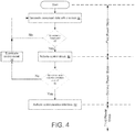
- FIG. 4 shown is an exemplary flow diagram representing steps that may be carried out by the electronic device 10 to determine whether to activate the electronic device 10 or revert to a low power state.
- FIG. 4 illustrates an exemplary process flow and, although illustrated in a logical progression, the illustrated blocks may be carried out in other orders and/or with concurrence between two or more blocks. Therefore, the illustrated flow diagram may be altered (including omitting steps) and/or may be implemented in an object-oriented manner or in a state-oriented manner.
- the logical flow may start in block 42.
- the electronic device 10 is in a first power state, where the communication interface 20 is deactivated, and the control circuit 14 is either deactivated or placed into a low power state. In this first power state, the electronic device 10 is conserving battery charge by only providing power to the sensor 24.
- the sensor 24 is used to generate data indicative of movement of the electronic device 10.
- the sensor 24 is an accelerometer assembly that outputs movement data in the form of raw accelerometer signals for up to three mutually orthogonal axes (e.g., an x-axis, a y-axis and a z-axis).
- the sensor is an accelerometer assembly that outputs movement data in the form of raw accelerometer signals measuring only the amplitude of acceleration.
- the movement data can be stored in the buffer 26.
- the buffer 26 can be configured to store a set amount of movement data corresponding to a fixed period of time.
- the buffer 26 may store movement data only for the previous three seconds.
- the sensor 24 can continuously overwrite the previous movement data on the buffer 26 so that old movement data (e.g., movement data outside of the fixed time period) is overwritten with new movement data.
- the movement data is compared to a threshold value.
- the sensor 24 includes a control circuit to perform this comparison.
- the control circuit 14 can perform this comparison.
- the threshold value can be an instantaneous magnitude of acceleration, or an average acceleration over a period of time. If the movement data does not exceed the threshold value, the electronic device 10 will remain in the first power state. Continuing in the first power state, the sensor 24 will continue to generate movement data, and store the movement data in the buffer 26. If the movement data exceeds the threshold value, the control circuit 14 is activated at block 46, or in embodiments where the control circuit 14 operates in a low power state during the first power state, the control circuit 14 is fully activated. Upon activation of the control circuit 14, the electronic device enters a second power state.
- the control circuit 14 receives the movement data stored in the buffer 26.
- the control circuit 14 analyzes the movement data to determine whether the movement data satisfies predetermined activation criteria.
- the predetermined activation criteria can include one or more predetermined motion patterns of the electronic device 10.
- the control circuit 14 can analyze the movement data to determine whether the movement data corresponds with a motion pattern representative of a user shaking the electronic device 10.
- the movement data analysis can involve comparing the movement data to the activation criteria using algorithms based on at least one of a frequency of changes in acceleration, a magnitude of acceleration, a number of changes in acceleration, or a specific pattern of acceleration changes such as a pattern of slow shakes alternated with fast shakes.
- algorithms used to compare the movement data with the activation criteria's movement pattern can be adapted by using a trained model.
- the trained model can involve collecting a plurality of sample movement data and using machine learning techniques to train a system to recognize positive motion patterns that correspond with a user shaking the electronic device 10 and distinguish such positive motion patterns from erroneous negative motion patterns that are to be ignored.
- a positive motion pattern can be required to have, for example, a specific pattern of changes in acceleration, a specific frequency of changes in acceleration, a specific frequency of changes in acceleration over a set time period, among others.
- Statistical models can be used to determine a confidence level that the movement data corresponds to a user shaking the electronic device 10.
- the control circuit 14 analyzes the movement data using a comparison algorithm to determine a percentage confidence level that the movement data represents a positive motion pattern.
- the control circuit 14 receives the movement data from the buffer 26 and analyzes the movement data using an algorithm.
- the control circuit 14 can determine by processing the movement data with the algorithm that the movement data represents a positive motion pattern with a 90% confidence level. If the 90% confidence level exceeds a confidence level threshold, then this movement data is considered a match to a positive motion pattern and the communication interface 20 is activated.
- a neural network can be developed.
- the neural network can be trained by sample data classified either as a positive motion pattern (e.g. a movement waveform that represents a user shaking the electronic device 10), or a negative motion pattern (e.g. a waveform that does not represent a user shaking the electronic device 10).
- the control circuit 14 can process the movement data using the learned neural network to classify the movement data as a positive motion pattern that satisfies the activation criteria, or a negative motion pattern that does not satisfy the activation criteria.
- a target waveform can be developed using a trained model. The target waveform is representative of a waveform derived from movement data corresponding to a user shaking the electronic device 10.
- the control circuit 14 can process the movement data by comparing the movement data waveform to the target waveform to derive an error value based on differences between the movement data waveform and the target waveform. The control circuit 14 can then compare the error value of the movement data to an error value threshold. If the error value of the movement data exceeds the error value threshold, then the activation criteria is not satisfied. If the error value of the movement data is less than the error threshold, then the activation criteria is satisfied.
- control circuit 14 can compare the movement data waveforms to multiple target waveforms representing different motion patterns.
- the movement data waveform can be compared to each of the target waveforms.
- the error value used to compare with the error value threshold can be the lowest error value of each of the error values as calculated with respect to each of the target waveforms. In this manner, the control circuit 14 can account for different motion patterns that may represent a user shaking the electronic device 10 to activate the electronic device 10.
- the electronic device 10 reverts back to the first power state when the control circuit 14 is deactivated or placed into a low power state at block 50, and only the sensor 24 is drawing power.
- the control circuit 14 can be disabled for a period of time in response to one or more consecutive determinations that the movement data does not satisfy the predetermined activation criteria.
- the control circuit 14 can be configured to disable itself after a set number of times of determining that the movement data does not satisfy the activation criteria. After disabling itself, the control circuit 14 will not activate for a set amount of time, even if the movement data from the sensor 24 satisfies the threshold value in the first power state. This feature can prevent repetitive control circuit 14 activations based on movement data from erroneous movement of the electronic device 10, such as from handling during shipment or travelling over a bumpy road.
- the communication interface 20 is activated at block 52.
- the communication interface 20 is activated and the electronic device enters a third power state where the sensor 24, the control circuit 14, and the communication interface 20 are all active.
- the electronic device 10 is considered to be activated while in the third power state.
- the electronic device 10 can establish communication with a host computer system 28. Once communications are established, the electronic device 10 can perform measurements and communicate data according to its programmed instructions. Further, the electronic device 10 can also report activation information pertaining to the electronic device 10 activation process to the host computing system 28.
- the activation information can include information such as the movement data, a timestamp of activation time, present GPS coordinates, or any other data pertaining to the electronic device's 10 activation or present condition upon activation.
- the algorithm training function 30 can use the activation information as a data sample to further train the model used in the development of the algorithm used by electronic devices 10 to analyze movement data.
- Data included in the activation information can be used to verify if the movement data truly was representative of a user shaking the electronic device 10. For example, a location of the electronic device at activation (e.g. as determined by GPS coordinates at the time of activation) can be compared to an expected end user location to determine if the electronic device 10 was shaken by the user or if the activation was due to a false positive. If the activation location is at an expected end user location, the movement data can be categorized as a positive motion pattern and used as a sample movement data to further train the algorithm or neural network. In this manner, the algorithm, neural network, and/or the target waveform can be continuously improved thereby improving the accuracy of the control circuit 14 in correctly identifying positive motion patterns that satisfy the predetermined activation criteria.
- the improved algorithms can be employed on subsequent electronic devices 10.
Landscapes
- Engineering & Computer Science (AREA)
- Theoretical Computer Science (AREA)
- General Engineering & Computer Science (AREA)
- Physics & Mathematics (AREA)
- General Physics & Mathematics (AREA)
- Computer Hardware Design (AREA)
- Human Computer Interaction (AREA)
- Computing Systems (AREA)
- Telephone Function (AREA)
- User Interface Of Digital Computer (AREA)
Abstract
Description
- The technology of the present disclosure relates generally to internet of things devices and, more particularly, to a method of analyzing a pattern of movement of a device to determine whether to activate the device from a reduced power state.
- Internet of things (loT) devices allow for network connectivity in non-standard networked devices. These loT devices are often sealed and/or ruggedized and include internal electronics with minimal or no user interface. When these devices are shipped to an end user, it is beneficial to ship the devices in a reduced power state to conserve battery life. For example, the loT devices may be shipped in a low power state where the device's controller and/or network interface are deactivated.
- But activation of loT devices has become an issue. Due to the lack of a user interface, the end user has limited options for "waking up" or activating the loT device from its low power state. One option is to configure the loT device to activate based on any detected movement measured by an accelerometer contained within the device. However, when using the accelerometer alone to make a decision whether to wake up the device, only simple threshold criteria is possible. This approach may erroneously activate the device during transit, causing the device's battery to be unnecessarily depleted while in transit.
- The disclosed approach includes analyzing movement data generated by a sensor (e.g., an accelerometer assembly) in the loT device to determine if the loT device should be activated from a reduced power state. A control circuit in the loT device can compare the movement data to a predetermined movement pattern to determine whether the movement should be ignored, or if the movement is consistent with a user shaking the device to activate the device. As a result of this approach, erroneous activation of the loT device is avoided, thereby preventing the loT device from needlessly depleting its battery before deployment by the end user.
- According to aspects of the disclosure, a method of activating an electronic device includes obtaining movement data indicative of movement of the electronic device; determining whether at least a portion of the movement data satisfies a predetermined activation criteria comprising one or more predetermined motion patterns of the electronic device; and activating a power state based on determining whether the portion of the movement data satisfies the predetermined activation criteria.
- According to one embodiment of the method, activating the power state includes reverting to a first power state in response to determining that the portion of the movement data does not satisfy the predetermined activation criteria, and reverting to the first power state includes deactivating a control circuit.
- According to one embodiment of the method, the method further includes disabling activation of the control circuit for a period of time in response to one or more consecutive determinations that the portion of the movement data does not satisfy the predetermined activation criteria.
- According to one embodiment of the method, activating the power state includes activating a third power state in response to determining that the portion of the movement data satisfies the predetermined activation criteria, and activating the third power state includes activating a communication interface.
- According to one embodiment of the method, the method further includes transmitting the movement data to a host computing system during the third power state.
- According to one embodiment of the method, the method further includes activating a second power state prior to obtaining the movement data, and activating the second power state includes activating a control circuit.
- According to one embodiment of the method, obtaining the movement data includes receiving the movement data from a buffer that is part of a sensor that generates the movement data.
- According to one embodiment of the method, the activation criteria includes at least one of a magnitude of acceleration, a change in acceleration, a number of changes in acceleration, or a predetermined pattern of acceleration changes.
- According to one embodiment of the method, the predetermined motion pattern is representative of a user shaking the electronic device.
- According to one embodiment of the method, the activation criteria includes a predetermined pattern of alternating acceleration.
- According to one embodiment of the method, determining whether the movement data satisfies the predetermined activation criteria includes applying a statistical model to compare the movement data to the predetermined activation criteria.
- According to one embodiment of the method, the predetermined activation criteria is based off of a trained model.
- According to one embodiment of the method, the movement data is representative of movement of the electronic device over a fixed period of time.
- According to one embodiment of the method, the movement data is acceleration data.
- According to aspects of the disclosure, an electronic device includes a communications interface, a sensor configured to generate movement data indicative of movement of the electronic device and a control circuit configured to obtain the movement data from the sensor. The control circuit is further configured to determine whether at least a portion of the movement data satisfies a predetermined activation criteria comprising a predetermined motion pattern of the electronic device. The control circuit is further configured to activate a power state based on determining whether the portion of the movement data satisfies the predetermined activation criteria.
- According to one embodiment of the electronic device, the control circuit is configured to activate a first power state in response to determining that the portion of the movement data does not satisfy the predetermined activation criteria, and activating the first power state includes deactivating the control circuit.
- According to one embodiment of the electronic device, the control circuit is further configured to disable activation of the control circuit for a period of time in response to one or more consecutive determinations that the portion of the movement data does not satisfy the predetermined activation criteria.
- According to one embodiment of the electronic device, the control circuit is configured to activate a third power state in response to determining that the portion of the movement data satisfies the predetermined activation criteria.
- According to one embodiment of the electronic device, activating the third power state includes activating the communications interface.
- According to one embodiment of the electronic device, the control circuit is further configured to transmit the movement data, using the communication interface, to a host computing system during the third power state.
- According to one embodiment of the electronic device, the control circuit is further configured to activate a second power state prior to obtaining the movement data from the sensor, wherein activating the second power state includes activating the control circuit.
- According to one embodiment of the electronic device, the control circuit is configured to activate the second power state in response to the movement data exceeding a predetermined threshold.
- According to one embodiment of the electronic device, the sensor comprises a buffer, and the control circuit is configured to obtain the movement data from the buffer.
- According to one embodiment of the electronic device, the sensor is further configured to overwrite the buffer when a buffer storage limit is reached.
- According to one embodiment of the electronic device, the activation criteria is at least one of a magnitude of acceleration, a change in acceleration, a number of changes in acceleration, or a predetermined pattern of acceleration changes.
- According to one embodiment of the electronic device, the predetermined motion pattern is representative of a user shaking the electronic device.
- According to one embodiment of the electronic device, the activation criteria includes a predetermined pattern of alternating acceleration.
- According to one embodiment of the electronic device, the control circuit is configured to determine whether the movement data satisfies a predetermined activation criteria by applying a statistical model to compare the movement data to the predetermined activation criteria.
- According to one embodiment of the electronic device, the predetermined activation criteria is based off a trained model.
- According to one embodiment of the electronic device, the movement data is representative of movement of the electronic device over a fixed period of time.
- According to one embodiment of the electronic device, the sensor is an accelerometer.
- According to aspects of the disclosure, a non-transitory computer-readable storage medium having stored thereon computer-executable instructions that, when executed, configure a control circuit to obtain movement data indicative of movement of an electronic device; determine whether the movement data satisfies a predetermined activation criteria comprising a predetermined motion pattern of the electronic device; deactivate the control circuit in response to determining that the movement data does not correspond to the predetermined activation criteria; and activate a communication interface in response to determining that the movement data corresponds to the predetermined activation criteria.
- According to one embodiment of the non-transitory computer-readable storage medium, the computer-executable instructions further configure the control circuit to transmit the movement data to a host computing system.
- According to one embodiment of the non-transitory computer-readable storage medium, the computer-executable instructions further configure the control circuit to disable activation of the control circuit for a period of time in response to one or more consecutive determinations that the movement data does not satisfy the predetermined activation criteria.
- According to one embodiment of the non-transitory computer-readable storage medium, the activation criteria is at least one of a magnitude of acceleration, a change in acceleration, a number of changes in acceleration, or a predetermined pattern of acceleration changes.
- According to one embodiment of the non-transitory computer-readable storage medium, the predetermined motion pattern is representative of a user shaking the electronic device.
- According to one embodiment of the non-transitory computer-readable storage medium, the activation criteria includes a predetermined pattern of alternating acceleration.
- According to one embodiment of the non-transitory computer-readable storage medium, the computer-executable instructions configure the control circuit to determine whether the movement data satisfies the predetermined activation criteria by applying a statistical model to compare the movement data to the predetermined activation criteria.
- According to one embodiment of the non-transitory computer-readable storage medium, the predetermined activation criteria is based off a trained model.
- According to one embodiment of the non-transitory computer-readable storage medium, the movement data is representative of movement of the electronic device over a fixed period of time.
-
-
FIG. 1 is a schematic diagram showing the electronic device, the electronic device is shown as part of a system. -
FIG. 2 schematically shows an exemplary electronic device attached to a representative object. -
FIG. 3 schematically shows a user activating an exemplary electronic device. -
FIG. 4 is a flow diagram of a representative method of analyzing the movement data. - Embodiments will now be described with reference to the drawings, wherein like reference numerals are used to refer to like elements throughout. It will be understood that the figures are not necessarily to scale. Features that are described and/or illustrated with respect to one embodiment may be used in the same way or in a similar way in one or more other embodiments and/or in combination with or instead of the features of the other embodiments.
- Described below, in conjunction with the appended figures, are various embodiments of internet of things (loT) devices, and systems and methods that determine whether to activate the loT device.
- With additional reference to
FIG. 1 , illustrated is an exemplary system for implementing the disclosed techniques. It will be appreciated that the illustrated system is representative and other systems may be used to implement the disclosed techniques. - The system includes the
electronic device 10. Theelectronic device 10 may be user devices, also known as user equipment or UEs, or machine-type devices. Exemplaryelectronic devices 10 include, but are not limited to internet-of-things devices (e.g. a trackable tag, or a wearable device), a device that uses machine-type communications, machine-to-machine (M2M) communications or device-to-device (D2D) communication (e.g., a sensor, a machine controller, an appliance, etc.), a mobile radiotelephones (such as "smartphones"), tablet computing devices, computers, a camera, a media player, or any other device that conducts wireless communications. Theelectronic device 10 is configured to carry out associated logical functions that are described herein. Theelectronic device 10 includes acontrol circuit 14 that is responsible for overall operation of theelectronic device 10. Theelectronic device 10 may include alogic execution circuit 16, such as a processor, that executes code to carry out various functions of theelectronic device 10. Logical functions and/or hardware of theelectronic device 10 may be implemented in other manners depending on the nature and configuration of theelectronic device 10. Therefore, the illustrated and described approaches are just examples and other approaches may be used including, but not limited to, thecontrol circuit 14 being implemented as, or including, hardware (e.g., a microprocessor, microcontroller, central processing unit (CPU), printed circuit board, etc.) or a combination of hardware and software (e.g., a system-on-chip (SoC), an application-specific integrated circuit (ASIC), field programmable gate array (FPGA), etc.). - The code executed by the
logic execution circuit 16 and data stored by theelectronic device 10 may be stored by amemory 18. The stored data may include, but is not limited to, data associated with the device activation functions of theelectronic device 10. - The
memory 18 may be, for example, one or more of a buffer, a flash memory, a hard drive, a removable media, a volatile memory, a non-volatile memory, a random access memory (RAM), or other suitable device. In a typical arrangement, thememory 18 includes a non-volatile (persistent) memory for long term data storage and a volatile memory that functions as system memory for thecontrol circuit 14. Thememory 18 is considered a non-transitory computer readable medium. - In some embodiments, the
electronic device 10 includes a communications interface 20 (e.g., communications circuitry) that enables theelectronic device 10 to transmit messages in broadcast format (e.g., without the establishment of a session with another device and/or without the expectation of a return response) or to establish a wireless communication connection with another device over acommunications medium 22 and send messages via the wireless communication connection. In the exemplary embodiment, thecommunications interface 20 includes a radio circuit. The radio circuit includes one or more radio frequency transceivers and at least one antenna assembly. Wired communications interfaces also may be present. In the embodiment where thecommunications interface 20 is operational to establish a wireless communication connection, thecommunications interface 20 andcommunications medium 22 may include coordinating transceivers. Exemplary transceivers include, but are not limited to, a cellular radio, a WiFi radio, a Bluetooth radio, a Bluetooth low energy (BLE) radio, or any other appropriate radio frequency transceiver. Also, an appropriate protocol may be followed by thecommunications interface 20 and/or thecommunications medium 22, such as a 3G, 4G or 5G protocol, an Internet or Things (loT) protocol, a machine to machine (M2M) protocol, a WiFi protocol, a Bluetooth or BLE protocol, etc. - The
electronic device 10 has asensor 24 configured to generate data indicative of movement of theelectronic device 10. Certain embodiments of thesensor 24 can generate data indicative of movement of theelectronic device 10 in three dimensions. In one embodiment, thesensor 24 is an accelerometer assembly. Another embodiment of theorientation sensor 24 is a gyro assembly.Sensor 24 can include itsown buffer 26 memory to store the movement data. Thebuffer 26 can be a physical memory such as a flash memory, a hard drive, a removable media, a volatile memory, a non-volatile memory, a random access memory (RAM), or other suitable device. In some embodiments, thebuffer 26 is a standalone memory that is part of thesensor 24. In other embodiments, thebuffer 26 can be incorporated into a portion of thememory 18. - It should be appreciated that the
electronic device 10 may include other sensors or components. The additional sensor or sensors may be, for example, a thermometer, a heart rate monitor, a vibration sensor, a camera, a microphone, a GPS transceiver, or any other appropriate device. Although not shown, theelectronic device 10 may further include a power supply unit that includes a battery for delivering operational power to the other components of theelectronic device 10. The battery may be rechargeable. - Data may be transmitted from the
electronic device 10 to ahost computing system 28, such as a server, a personal computer, a portable user equipment (e.g., a smartphone), etc. Thehost computing system 28 may be implemented as a computer-based system that is capable of executing computer applications (e.g., software programs). An exemplary application includes analgorithm training function 30. Thealgorithm training function 30, when executed, carries out functions of thehost computing system 28 that are described herein. Thealgorithm training function 30, any other applications and an operating system executed by thehost computing system 28, and adata store 32 may be stored on a non-transitory computer readable medium, such as amemory 34. Thedata store 32 may be used to store various information sets used to carry out the functions described in this disclosure. Thememory 34 may be, for example, a magnetic, optical or electronic storage device (e.g., hard disk, optical disk, flash memory, etc.), and may comprise several devices, including volatile and non-volatile memory components. Accordingly, thememory 34 may include, for example, random access memory (RAM) for acting as system memory, read-only memory (ROM), solid-state drives, hard disks, optical disks, tapes, flash devices and/or other memory components, plus associated drives, players and/or readers for the memory devices. - To execute logical operations, the
host computing system 28 may include one ormore processors 36 used to execute instructions that carry out logic routines. Theprocessor 36 and thememory 34 may be coupled using alocal interface 38. Thelocal interface 38 may be, for example, a data bus with accompanying control bus, a network, or other subsystem. - The
host computing system 28 may have various input/output (I/O) interfaces for operatively connecting to various peripheral devices. Thehost computing system 28 also may have one or more communications interfaces 40. Thecommunications interface 40 may include for example, a modem and/or a network interface card. Thecommunications interface 40 enables thehost computing system 28 to send and receive data to and from other computing devices via thecommunications medium 22. Also, thecommunications interface 40 enables thehost computing system 28 to receive messages and data from theelectronic device 10 either directly or by way of thecommunications medium 22. Thecommunications medium 22 may be any network platform and may include multiple network platforms. Exemplary network platforms include, but are not limited to, a WiFi network, a cellular network, etc. -
FIG. 2 shows an exemplaryelectronic device 10 attached to anobject 12. In the illustrated embodiment, theelectronic device 10 is a tag and theobject 12 is an animal maintained as livestock with a number of other similar animals. The animal of the illustrated embodiment is a pig. It will be understood that the tag may be used with other types of animals or with other types of objects, which need not be living. - In the exemplary context shown in
FIG. 2 , theelectronic device 10 is attached to the pig with a piercing through an ear of the pig. Other attachment mechanisms may be employed and the attachment mechanism may be changed depending on the type ofobject 12 to which theelectronic device 10 is attached. For instance, in the case of a bird, theelectronic device 10 may be pierced to a wing of the bird. Alternatively, theelectronic device 10 may be attached using a band placed around a leg of the animal. In the case of non-living objects, the tag may be attached with adhesive, a strap, a threaded fastener, or any other appropriate connector. The tag in this example can be used to track a location or movement of an animal or an object.Electronic devices 10 such as the tag may be shipped to an end user of theelectronic device 10. In order to conserve battery life, theelectronic device 10 is placed into a low power state while in transit, prior to being placed into service by an end user. Upon receiving theelectronic device 10, the end user may be instructed to shake theelectronic device 10 in a certain pattern to activate theelectronic device 10, as shown inFIG. 3 . - Turning now to
FIG. 4 , shown is an exemplary flow diagram representing steps that may be carried out by theelectronic device 10 to determine whether to activate theelectronic device 10 or revert to a low power state.FIG. 4 illustrates an exemplary process flow and, although illustrated in a logical progression, the illustrated blocks may be carried out in other orders and/or with concurrence between two or more blocks. Therefore, the illustrated flow diagram may be altered (including omitting steps) and/or may be implemented in an object-oriented manner or in a state-oriented manner. - The logical flow may start in
block 42. Atblock 42, theelectronic device 10 is in a first power state, where thecommunication interface 20 is deactivated, and thecontrol circuit 14 is either deactivated or placed into a low power state. In this first power state, theelectronic device 10 is conserving battery charge by only providing power to thesensor 24. Inblock 42, thesensor 24 is used to generate data indicative of movement of theelectronic device 10. In one embodiment, thesensor 24 is an accelerometer assembly that outputs movement data in the form of raw accelerometer signals for up to three mutually orthogonal axes (e.g., an x-axis, a y-axis and a z-axis). In another embodiment, the sensor is an accelerometer assembly that outputs movement data in the form of raw accelerometer signals measuring only the amplitude of acceleration. As thesensor 24 generates the movement data, the movement data can be stored in thebuffer 26. Thebuffer 26 can be configured to store a set amount of movement data corresponding to a fixed period of time. By way of example and not limitation, thebuffer 26 may store movement data only for the previous three seconds. Thesensor 24 can continuously overwrite the previous movement data on thebuffer 26 so that old movement data (e.g., movement data outside of the fixed time period) is overwritten with new movement data. - At
block 44, the movement data is compared to a threshold value. In one embodiment, thesensor 24 includes a control circuit to perform this comparison. In another embodiment, thecontrol circuit 14 can perform this comparison. For example, the threshold value can be an instantaneous magnitude of acceleration, or an average acceleration over a period of time. If the movement data does not exceed the threshold value, theelectronic device 10 will remain in the first power state. Continuing in the first power state, thesensor 24 will continue to generate movement data, and store the movement data in thebuffer 26. If the movement data exceeds the threshold value, thecontrol circuit 14 is activated atblock 46, or in embodiments where thecontrol circuit 14 operates in a low power state during the first power state, thecontrol circuit 14 is fully activated. Upon activation of thecontrol circuit 14, the electronic device enters a second power state. - During the second power state and upon the control circuit's 14 activation, the
control circuit 14 receives the movement data stored in thebuffer 26. Atblock 48, thecontrol circuit 14 analyzes the movement data to determine whether the movement data satisfies predetermined activation criteria. The predetermined activation criteria can include one or more predetermined motion patterns of theelectronic device 10. For example, thecontrol circuit 14 can analyze the movement data to determine whether the movement data corresponds with a motion pattern representative of a user shaking theelectronic device 10. The movement data analysis can involve comparing the movement data to the activation criteria using algorithms based on at least one of a frequency of changes in acceleration, a magnitude of acceleration, a number of changes in acceleration, or a specific pattern of acceleration changes such as a pattern of slow shakes alternated with fast shakes. - In certain embodiments, algorithms used to compare the movement data with the activation criteria's movement pattern can be adapted by using a trained model. The trained model can involve collecting a plurality of sample movement data and using machine learning techniques to train a system to recognize positive motion patterns that correspond with a user shaking the
electronic device 10 and distinguish such positive motion patterns from erroneous negative motion patterns that are to be ignored. A positive motion pattern can be required to have, for example, a specific pattern of changes in acceleration, a specific frequency of changes in acceleration, a specific frequency of changes in acceleration over a set time period, among others. Statistical models can be used to determine a confidence level that the movement data corresponds to a user shaking theelectronic device 10. In one embodiment, thecontrol circuit 14 analyzes the movement data using a comparison algorithm to determine a percentage confidence level that the movement data represents a positive motion pattern. By way of example and not limitation, thecontrol circuit 14 receives the movement data from thebuffer 26 and analyzes the movement data using an algorithm. Thecontrol circuit 14 can determine by processing the movement data with the algorithm that the movement data represents a positive motion pattern with a 90% confidence level. If the 90% confidence level exceeds a confidence level threshold, then this movement data is considered a match to a positive motion pattern and thecommunication interface 20 is activated. - In certain embodiments, a neural network can be developed. The neural network can be trained by sample data classified either as a positive motion pattern (e.g. a movement waveform that represents a user shaking the electronic device 10), or a negative motion pattern (e.g. a waveform that does not represent a user shaking the electronic device 10). The
control circuit 14 can process the movement data using the learned neural network to classify the movement data as a positive motion pattern that satisfies the activation criteria, or a negative motion pattern that does not satisfy the activation criteria. In certain embodiments, a target waveform can be developed using a trained model. The target waveform is representative of a waveform derived from movement data corresponding to a user shaking theelectronic device 10. Thecontrol circuit 14 can process the movement data by comparing the movement data waveform to the target waveform to derive an error value based on differences between the movement data waveform and the target waveform. Thecontrol circuit 14 can then compare the error value of the movement data to an error value threshold. If the error value of the movement data exceeds the error value threshold, then the activation criteria is not satisfied. If the error value of the movement data is less than the error threshold, then the activation criteria is satisfied. - In certain embodiments, the
control circuit 14 can compare the movement data waveforms to multiple target waveforms representing different motion patterns. In these embodiments, the movement data waveform can be compared to each of the target waveforms. In this situation, the error value used to compare with the error value threshold can be the lowest error value of each of the error values as calculated with respect to each of the target waveforms. In this manner, thecontrol circuit 14 can account for different motion patterns that may represent a user shaking theelectronic device 10 to activate theelectronic device 10. - If the movement data does not satisfy the activation criteria, the
electronic device 10 reverts back to the first power state when thecontrol circuit 14 is deactivated or placed into a low power state atblock 50, and only thesensor 24 is drawing power. In some embodiments, thecontrol circuit 14 can be disabled for a period of time in response to one or more consecutive determinations that the movement data does not satisfy the predetermined activation criteria. For example, thecontrol circuit 14 can be configured to disable itself after a set number of times of determining that the movement data does not satisfy the activation criteria. After disabling itself, thecontrol circuit 14 will not activate for a set amount of time, even if the movement data from thesensor 24 satisfies the threshold value in the first power state. This feature can preventrepetitive control circuit 14 activations based on movement data from erroneous movement of theelectronic device 10, such as from handling during shipment or travelling over a bumpy road. - On the other hand, if the movement data satisfies the activation criteria in
block 48, thecommunication interface 20 is activated atblock 52. Atblock 52, thecommunication interface 20 is activated and the electronic device enters a third power state where thesensor 24, thecontrol circuit 14, and thecommunication interface 20 are all active. Theelectronic device 10 is considered to be activated while in the third power state. Once thecommunication interface 20 is active, theelectronic device 10 can establish communication with ahost computer system 28. Once communications are established, theelectronic device 10 can perform measurements and communicate data according to its programmed instructions. Further, theelectronic device 10 can also report activation information pertaining to theelectronic device 10 activation process to thehost computing system 28. The activation information can include information such as the movement data, a timestamp of activation time, present GPS coordinates, or any other data pertaining to the electronic device's 10 activation or present condition upon activation. - After being communicated to the host computing system, the
algorithm training function 30 can use the activation information as a data sample to further train the model used in the development of the algorithm used byelectronic devices 10 to analyze movement data. Data included in the activation information can be used to verify if the movement data truly was representative of a user shaking theelectronic device 10. For example, a location of the electronic device at activation (e.g. as determined by GPS coordinates at the time of activation) can be compared to an expected end user location to determine if theelectronic device 10 was shaken by the user or if the activation was due to a false positive. If the activation location is at an expected end user location, the movement data can be categorized as a positive motion pattern and used as a sample movement data to further train the algorithm or neural network. In this manner, the algorithm, neural network, and/or the target waveform can be continuously improved thereby improving the accuracy of thecontrol circuit 14 in correctly identifying positive motion patterns that satisfy the predetermined activation criteria. The improved algorithms can be employed on subsequentelectronic devices 10. - Although certain embodiments have been shown and described, it is understood that equivalents and modifications falling within the scope of the appended claims will occur to others who are skilled in the art upon the reading and understanding of this specification.
Claims (15)
- A method of activating an electronic device (10) comprising:obtaining movement data indicative of movement of the electronic device (10);determining (48) whether at least a portion of the movement data satisfies a predetermined activation criteria comprising one or more predetermined motion patterns of the electronic device (10);activating (50, 52) a power state based on determining whether the portion of the movement data satisfies the predetermined activation criteria; anddisabling activation of the control circuit for a period of time in response to one or more consecutive determinations that the portion of the movement data does not satisfy the predetermined activation criteria.
- The method of claim 1, wherein activating (50, 52) the power state comprises reverting to a first power state in response to determining that the portion of the movement data does not satisfy the predetermined activation criteria, wherein reverting to the first power state includes deactivating (50) a control circuit.
- The method of claim 1, wherein activating (50, 52) the power state comprises activating a third power state in response to determining that the portion of the movement data satisfies the predetermined activation criteria, wherein activating the third power state includes activating (52) a communication interface.
- The method of claim 3, further comprising:
transmitting the movement data to a host computing system during the third power state. - The method of any one of claims 1-4, further comprising:
activating a second power state prior to obtaining the movement data, wherein activating the second power state includes activating (46) a control circuit. - The method of any one of claims 1-5, wherein obtaining the movement data includes receiving the movement data from a buffer (26) that is part of a sensor (24) that generates the movement data.
- The method of any one of claims 1-6, wherein the activation criteria includes at least one of a magnitude of acceleration, a change in acceleration, a number of changes in acceleration, or a predetermined pattern of acceleration changes.
- The method of any one of claims 1-7, wherein the predetermined motion pattern is representative of a user shaking the electronic device (10).
- The method of any one of claims 1-8, wherein the activation criteria includes a predetermined pattern of alternating acceleration.
- The method of any one of claims 1-9, wherein determining (48) whether the movement data satisfies the predetermined activation criteria includes applying a statistical model to compare the movement data to the predetermined activation criteria.
- The method of any one of claims 1-10, wherein the predetermined activation criteria is based off of a trained model.
- The method of any one of claims 1-11, wherein the movement data is representative of movement of the electronic device (10) over a fixed period of time.
- The method of any of claims 1-12, wherein the movement data is acceleration data.
- An electronic device (10) comprising:a communications interface (20);a sensor (24) configured to:
generate movement data indicative of movement of the electronic device (10); anda control circuit (14) configured to:obtain the movement data from the sensor;determine whether at least a portion of the movement data satisfies a predetermined activation criteria comprising a predetermined motion pattern of the electronic device (10);activate a power state based on determining whether the portion of the movement data satisfies the predetermined activation criteria; anddisable activation of the control circuit for a period of time in response to one or more consecutive determinations that the portion of the movement data does not satisfy the predetermined activation criteria. - A non-transitory computer-readable storage medium (18) having stored thereon computer-executable instructions that, when executed, configure a control circuit (14) to:obtain movement data indicative of movement of an electronic device (10);determine whether the movement data satisfies a predetermined activation criteria comprising a predetermined motion pattern of the electronic device (10);deactivate the control circuit (14) in response to determining that the movement data does not correspond to the predetermined activation criteria; andactivate a communication interface (20) in response to determining that the movement data corresponds to the predetermined activation criteria.
Applications Claiming Priority (1)
| Application Number | Priority Date | Filing Date | Title |
|---|---|---|---|
| SE1830309 | 2018-10-29 |
Publications (2)
| Publication Number | Publication Date |
|---|---|
| EP3647904A1 true EP3647904A1 (en) | 2020-05-06 |
| EP3647904B1 EP3647904B1 (en) | 2022-06-22 |
Family
ID=67539298
Family Applications (1)
| Application Number | Title | Priority Date | Filing Date |
|---|---|---|---|
| EP19189664.6A Active EP3647904B1 (en) | 2018-10-29 | 2019-08-01 | Method and system for device activation |
Country Status (2)
| Country | Link |
|---|---|
| US (1) | US11119558B2 (en) |
| EP (1) | EP3647904B1 (en) |
Families Citing this family (11)
| Publication number | Priority date | Publication date | Assignee | Title |
|---|---|---|---|---|
| US11030618B1 (en) | 2016-09-30 | 2021-06-08 | Winkk, Inc. | Authentication and personal data sharing for partner services using out-of-band optical mark recognition |
| US11580421B2 (en) * | 2019-10-16 | 2023-02-14 | Qualcomm Incorporated | Weakly supervised learning for improving multimodal sensing platform |
| US12335399B2 (en) | 2019-12-10 | 2025-06-17 | Winkk, Inc. | User as a password |
| US11553337B2 (en) | 2019-12-10 | 2023-01-10 | Winkk, Inc. | Method and apparatus for encryption key exchange with enhanced security through opti-encryption channel |
| US20220197985A1 (en) * | 2019-12-10 | 2022-06-23 | Winkk, Inc | User identification based on a shake challenge |
| US11574045B2 (en) | 2019-12-10 | 2023-02-07 | Winkk, Inc. | Automated ID proofing using a random multitude of real-time behavioral biometric samplings |
| US12341790B2 (en) | 2019-12-10 | 2025-06-24 | Winkk, Inc. | Device behavior analytics |
| US11843943B2 (en) | 2021-06-04 | 2023-12-12 | Winkk, Inc. | Dynamic key exchange for moving target |
| US12438731B2 (en) | 2022-09-21 | 2025-10-07 | Winkk, Inc. | Diophantine system for digital signatures |
| JPWO2024166194A1 (en) * | 2023-02-07 | 2024-08-15 | ||
| US12298831B2 (en) * | 2023-06-22 | 2025-05-13 | Qualcomm Incorporated | Presence detection using compressive sampling |
Citations (3)
| Publication number | Priority date | Publication date | Assignee | Title |
|---|---|---|---|---|
| US20100085203A1 (en) * | 2008-10-08 | 2010-04-08 | Philippe Kahn | Method and System for Waking Up a Device Due to Motion |
| US20150095678A1 (en) * | 2013-09-27 | 2015-04-02 | Lama Nachman | Movement-based state modification |
| WO2018143871A1 (en) * | 2017-01-31 | 2018-08-09 | Outsmart Ab | Device and method for motion detection |
Family Cites Families (9)
| Publication number | Priority date | Publication date | Assignee | Title |
|---|---|---|---|---|
| GB251550A (en) | 1925-06-25 | 1926-05-06 | Societe Des Appareils Mephisto, Jules Manfredi & Cie. | |
| US6442286B1 (en) * | 1998-12-22 | 2002-08-27 | Stmicroelectronics, Inc. | High security flash memory and method |
| US7873849B2 (en) | 2009-09-02 | 2011-01-18 | Apple Inc. | Motion sensor data processing using various power management modes |
| US20110223974A1 (en) * | 2010-03-10 | 2011-09-15 | Sony Ericsson Mobile Communications Ab | Mobile communication device and method for operating a mobile communication device |
| US8510552B2 (en) | 2010-04-07 | 2013-08-13 | Apple Inc. | System and method for file-level data protection |
| EP2485542B1 (en) | 2011-02-03 | 2019-02-27 | Sony Corporation | Portable electronic device and operation method for establishing a near field communication link |
| US20150291127A1 (en) * | 2014-04-15 | 2015-10-15 | Lear Corporation | Wireless device with accelerometer for optimizing polling |
| EP3170062B1 (en) * | 2014-07-18 | 2019-08-21 | Apple Inc. | Raise gesture detection in a device |
| EP3067784A1 (en) | 2015-03-11 | 2016-09-14 | Gemalto Sa | A prehensile near field communications system controllable by a shaking gesture |
-
2019
- 2019-07-25 US US16/522,598 patent/US11119558B2/en active Active
- 2019-08-01 EP EP19189664.6A patent/EP3647904B1/en active Active
Patent Citations (3)
| Publication number | Priority date | Publication date | Assignee | Title |
|---|---|---|---|---|
| US20100085203A1 (en) * | 2008-10-08 | 2010-04-08 | Philippe Kahn | Method and System for Waking Up a Device Due to Motion |
| US20150095678A1 (en) * | 2013-09-27 | 2015-04-02 | Lama Nachman | Movement-based state modification |
| WO2018143871A1 (en) * | 2017-01-31 | 2018-08-09 | Outsmart Ab | Device and method for motion detection |
Also Published As
| Publication number | Publication date |
|---|---|
| US20200133373A1 (en) | 2020-04-30 |
| EP3647904B1 (en) | 2022-06-22 |
| US11119558B2 (en) | 2021-09-14 |
Similar Documents
| Publication | Publication Date | Title |
|---|---|---|
| US11119558B2 (en) | Method and system for device activation | |
| US9141181B2 (en) | Low power event processing for sensor controllers | |
| US10013048B2 (en) | Reconfigurable event driven hardware using reservoir computing for monitoring an electronic sensor and waking a processor | |
| US20170164293A1 (en) | Mobile device and method for controlling sensor by the mobile device | |
| US20180329713A1 (en) | Fitness sensor with low power attributes in sensor hub | |
| JP2020503750A (en) | Determining the proximity of the transmission antenna to the human body to limit the transmitted output power | |
| US20170313190A1 (en) | Method of controlling alerting driver, alerting control device, driving support method, driving support device, and computer-readable recording medium | |
| ES2811067T3 (en) | App and mobile terminal control method | |
| CN110179471A (en) | Tumble detection method, tumble detection device, tumble detection apparatus, and storage medium | |
| US20190175016A1 (en) | Calculate Physiological State and Control Smart Environments via Wearable Sensing Elements | |
| CN114727909B (en) | Monitoring system for feeding bottles | |
| JP2018514095A (en) | On-device behavior analysis to detect malfunctions due to RF interference | |
| WO2018218786A1 (en) | Pet worn device and pet information transmission method therefor | |
| EP3611944B1 (en) | Method and control arrangement for controlling a response time of a wireless sensor device | |
| CN116157056B (en) | Systems and methods for effectively managing the power consumption of animal monitoring devices | |
| US11556748B2 (en) | Methods and apparatus to improve accuracy of edge and/or a fog-based classification | |
| CN107978135A (en) | A kind of correcting sitting posture control device and method | |
| KR20220000767A (en) | Pet monitoring system and monitoring method through wearable device | |
| US20150103633A1 (en) | Adaptive timing congfiguration for athletic devices | |
| US12127531B2 (en) | Livestock age verification system | |
| US11406086B2 (en) | Device, method, and program for detecting injury of quadruped | |
| JP2020512615A (en) | Method, system and computer program for determining a fall response of a subject | |
| CN106960542A (en) | A kind of low-power consumption falling detection device based on interruption driving | |
| CN119937804B (en) | Stylus control method, device, stylus and storage medium | |
| US20210004695A1 (en) | Electronic apparatus and information processing system |
Legal Events
| Date | Code | Title | Description |
|---|---|---|---|
| PUAI | Public reference made under article 153(3) epc to a published international application that has entered the european phase |
Free format text: ORIGINAL CODE: 0009012 |
|
| STAA | Information on the status of an ep patent application or granted ep patent |
Free format text: STATUS: REQUEST FOR EXAMINATION WAS MADE |
|
| 17P | Request for examination filed |
Effective date: 20190801 |
|
| AK | Designated contracting states |
Kind code of ref document: A1 Designated state(s): AL AT BE BG CH CY CZ DE DK EE ES FI FR GB GR HR HU IE IS IT LI LT LU LV MC MK MT NL NO PL PT RO RS SE SI SK SM TR |
|
| AX | Request for extension of the european patent |
Extension state: BA ME |
|
| RAP1 | Party data changed (applicant data changed or rights of an application transferred) |
Owner name: SONY CORPORATION |
|
| RAP3 | Party data changed (applicant data changed or rights of an application transferred) |
Owner name: SONY GROUP CORPORATION |
|
| RIC1 | Information provided on ipc code assigned before grant |
Ipc: G06F 3/01 20060101ALI20211216BHEP Ipc: G06F 1/16 20060101ALI20211216BHEP Ipc: G06F 1/3231 20190101AFI20211216BHEP |
|
| GRAP | Despatch of communication of intention to grant a patent |
Free format text: ORIGINAL CODE: EPIDOSNIGR1 |
|
| STAA | Information on the status of an ep patent application or granted ep patent |
Free format text: STATUS: GRANT OF PATENT IS INTENDED |
|
| INTG | Intention to grant announced |
Effective date: 20220202 |
|
| GRAS | Grant fee paid |
Free format text: ORIGINAL CODE: EPIDOSNIGR3 |
|
| GRAA | (expected) grant |
Free format text: ORIGINAL CODE: 0009210 |
|
| STAA | Information on the status of an ep patent application or granted ep patent |
Free format text: STATUS: THE PATENT HAS BEEN GRANTED |
|
| AK | Designated contracting states |
Kind code of ref document: B1 Designated state(s): AL AT BE BG CH CY CZ DE DK EE ES FI FR GB GR HR HU IE IS IT LI LT LU LV MC MK MT NL NO PL PT RO RS SE SI SK SM TR |
|
| REG | Reference to a national code |
Ref country code: GB Ref legal event code: FG4D |
|
| REG | Reference to a national code |
Ref country code: CH Ref legal event code: EP |
|
| REG | Reference to a national code |
Ref country code: DE Ref legal event code: R096 Ref document number: 602019016083 Country of ref document: DE |
|
| REG | Reference to a national code |
Ref country code: AT Ref legal event code: REF Ref document number: 1500192 Country of ref document: AT Kind code of ref document: T Effective date: 20220715 |
|
| REG | Reference to a national code |
Ref country code: IE Ref legal event code: FG4D |
|
| REG | Reference to a national code |
Ref country code: LT Ref legal event code: MG9D |
|
| REG | Reference to a national code |
Ref country code: NL Ref legal event code: MP Effective date: 20220622 |
|
| PG25 | Lapsed in a contracting state [announced via postgrant information from national office to epo] |
Ref country code: SE Free format text: LAPSE BECAUSE OF FAILURE TO SUBMIT A TRANSLATION OF THE DESCRIPTION OR TO PAY THE FEE WITHIN THE PRESCRIBED TIME-LIMIT Effective date: 20220622 Ref country code: NO Free format text: LAPSE BECAUSE OF FAILURE TO SUBMIT A TRANSLATION OF THE DESCRIPTION OR TO PAY THE FEE WITHIN THE PRESCRIBED TIME-LIMIT Effective date: 20220922 Ref country code: LT Free format text: LAPSE BECAUSE OF FAILURE TO SUBMIT A TRANSLATION OF THE DESCRIPTION OR TO PAY THE FEE WITHIN THE PRESCRIBED TIME-LIMIT Effective date: 20220622 Ref country code: HR Free format text: LAPSE BECAUSE OF FAILURE TO SUBMIT A TRANSLATION OF THE DESCRIPTION OR TO PAY THE FEE WITHIN THE PRESCRIBED TIME-LIMIT Effective date: 20220622 Ref country code: GR Free format text: LAPSE BECAUSE OF FAILURE TO SUBMIT A TRANSLATION OF THE DESCRIPTION OR TO PAY THE FEE WITHIN THE PRESCRIBED TIME-LIMIT Effective date: 20220923 Ref country code: FI Free format text: LAPSE BECAUSE OF FAILURE TO SUBMIT A TRANSLATION OF THE DESCRIPTION OR TO PAY THE FEE WITHIN THE PRESCRIBED TIME-LIMIT Effective date: 20220622 Ref country code: BG Free format text: LAPSE BECAUSE OF FAILURE TO SUBMIT A TRANSLATION OF THE DESCRIPTION OR TO PAY THE FEE WITHIN THE PRESCRIBED TIME-LIMIT Effective date: 20220922 |
|
| REG | Reference to a national code |
Ref country code: AT Ref legal event code: MK05 Ref document number: 1500192 Country of ref document: AT Kind code of ref document: T Effective date: 20220622 |
|
| PG25 | Lapsed in a contracting state [announced via postgrant information from national office to epo] |
Ref country code: RS Free format text: LAPSE BECAUSE OF FAILURE TO SUBMIT A TRANSLATION OF THE DESCRIPTION OR TO PAY THE FEE WITHIN THE PRESCRIBED TIME-LIMIT Effective date: 20220622 Ref country code: LV Free format text: LAPSE BECAUSE OF FAILURE TO SUBMIT A TRANSLATION OF THE DESCRIPTION OR TO PAY THE FEE WITHIN THE PRESCRIBED TIME-LIMIT Effective date: 20220622 |
|
| PG25 | Lapsed in a contracting state [announced via postgrant information from national office to epo] |
Ref country code: NL Free format text: LAPSE BECAUSE OF FAILURE TO SUBMIT A TRANSLATION OF THE DESCRIPTION OR TO PAY THE FEE WITHIN THE PRESCRIBED TIME-LIMIT Effective date: 20220622 |
|
| PG25 | Lapsed in a contracting state [announced via postgrant information from national office to epo] |
Ref country code: SM Free format text: LAPSE BECAUSE OF FAILURE TO SUBMIT A TRANSLATION OF THE DESCRIPTION OR TO PAY THE FEE WITHIN THE PRESCRIBED TIME-LIMIT Effective date: 20220622 Ref country code: SK Free format text: LAPSE BECAUSE OF FAILURE TO SUBMIT A TRANSLATION OF THE DESCRIPTION OR TO PAY THE FEE WITHIN THE PRESCRIBED TIME-LIMIT Effective date: 20220622 Ref country code: RO Free format text: LAPSE BECAUSE OF FAILURE TO SUBMIT A TRANSLATION OF THE DESCRIPTION OR TO PAY THE FEE WITHIN THE PRESCRIBED TIME-LIMIT Effective date: 20220622 Ref country code: PT Free format text: LAPSE BECAUSE OF FAILURE TO SUBMIT A TRANSLATION OF THE DESCRIPTION OR TO PAY THE FEE WITHIN THE PRESCRIBED TIME-LIMIT Effective date: 20221024 Ref country code: ES Free format text: LAPSE BECAUSE OF FAILURE TO SUBMIT A TRANSLATION OF THE DESCRIPTION OR TO PAY THE FEE WITHIN THE PRESCRIBED TIME-LIMIT Effective date: 20220622 Ref country code: EE Free format text: LAPSE BECAUSE OF FAILURE TO SUBMIT A TRANSLATION OF THE DESCRIPTION OR TO PAY THE FEE WITHIN THE PRESCRIBED TIME-LIMIT Effective date: 20220622 Ref country code: CZ Free format text: LAPSE BECAUSE OF FAILURE TO SUBMIT A TRANSLATION OF THE DESCRIPTION OR TO PAY THE FEE WITHIN THE PRESCRIBED TIME-LIMIT Effective date: 20220622 Ref country code: AT Free format text: LAPSE BECAUSE OF FAILURE TO SUBMIT A TRANSLATION OF THE DESCRIPTION OR TO PAY THE FEE WITHIN THE PRESCRIBED TIME-LIMIT Effective date: 20220622 |
|
| PG25 | Lapsed in a contracting state [announced via postgrant information from national office to epo] |
Ref country code: PL Free format text: LAPSE BECAUSE OF FAILURE TO SUBMIT A TRANSLATION OF THE DESCRIPTION OR TO PAY THE FEE WITHIN THE PRESCRIBED TIME-LIMIT Effective date: 20220622 Ref country code: IS Free format text: LAPSE BECAUSE OF FAILURE TO SUBMIT A TRANSLATION OF THE DESCRIPTION OR TO PAY THE FEE WITHIN THE PRESCRIBED TIME-LIMIT Effective date: 20221022 |
|
| REG | Reference to a national code |
Ref country code: DE Ref legal event code: R097 Ref document number: 602019016083 Country of ref document: DE |
|
| PG25 | Lapsed in a contracting state [announced via postgrant information from national office to epo] |
Ref country code: MC Free format text: LAPSE BECAUSE OF FAILURE TO SUBMIT A TRANSLATION OF THE DESCRIPTION OR TO PAY THE FEE WITHIN THE PRESCRIBED TIME-LIMIT Effective date: 20220622 Ref country code: AL Free format text: LAPSE BECAUSE OF FAILURE TO SUBMIT A TRANSLATION OF THE DESCRIPTION OR TO PAY THE FEE WITHIN THE PRESCRIBED TIME-LIMIT Effective date: 20220622 |
|
| REG | Reference to a national code |
Ref country code: CH Ref legal event code: PL |
|
| PG25 | Lapsed in a contracting state [announced via postgrant information from national office to epo] |
Ref country code: LU Free format text: LAPSE BECAUSE OF NON-PAYMENT OF DUE FEES Effective date: 20220801 Ref country code: LI Free format text: LAPSE BECAUSE OF NON-PAYMENT OF DUE FEES Effective date: 20220831 Ref country code: DK Free format text: LAPSE BECAUSE OF FAILURE TO SUBMIT A TRANSLATION OF THE DESCRIPTION OR TO PAY THE FEE WITHIN THE PRESCRIBED TIME-LIMIT Effective date: 20220622 Ref country code: CH Free format text: LAPSE BECAUSE OF NON-PAYMENT OF DUE FEES Effective date: 20220831 |
|
| PLBE | No opposition filed within time limit |
Free format text: ORIGINAL CODE: 0009261 |
|
| STAA | Information on the status of an ep patent application or granted ep patent |
Free format text: STATUS: NO OPPOSITION FILED WITHIN TIME LIMIT |
|
| REG | Reference to a national code |
Ref country code: BE Ref legal event code: MM Effective date: 20220831 |
|
| 26N | No opposition filed |
Effective date: 20230323 |
|
| P01 | Opt-out of the competence of the unified patent court (upc) registered |
Effective date: 20230528 |
|
| PG25 | Lapsed in a contracting state [announced via postgrant information from national office to epo] |
Ref country code: IE Free format text: LAPSE BECAUSE OF NON-PAYMENT OF DUE FEES Effective date: 20220801 Ref country code: FR Free format text: LAPSE BECAUSE OF NON-PAYMENT OF DUE FEES Effective date: 20220822 |
|
| PG25 | Lapsed in a contracting state [announced via postgrant information from national office to epo] |
Ref country code: SI Free format text: LAPSE BECAUSE OF FAILURE TO SUBMIT A TRANSLATION OF THE DESCRIPTION OR TO PAY THE FEE WITHIN THE PRESCRIBED TIME-LIMIT Effective date: 20220622 |
|
| PG25 | Lapsed in a contracting state [announced via postgrant information from national office to epo] |
Ref country code: BE Free format text: LAPSE BECAUSE OF NON-PAYMENT OF DUE FEES Effective date: 20220831 |
|
| PG25 | Lapsed in a contracting state [announced via postgrant information from national office to epo] |
Ref country code: IT Free format text: LAPSE BECAUSE OF FAILURE TO SUBMIT A TRANSLATION OF THE DESCRIPTION OR TO PAY THE FEE WITHIN THE PRESCRIBED TIME-LIMIT Effective date: 20220622 |
|
| PG25 | Lapsed in a contracting state [announced via postgrant information from national office to epo] |
Ref country code: HU Free format text: LAPSE BECAUSE OF FAILURE TO SUBMIT A TRANSLATION OF THE DESCRIPTION OR TO PAY THE FEE WITHIN THE PRESCRIBED TIME-LIMIT; INVALID AB INITIO Effective date: 20190801 |
|
| PG25 | Lapsed in a contracting state [announced via postgrant information from national office to epo] |
Ref country code: MK Free format text: LAPSE BECAUSE OF FAILURE TO SUBMIT A TRANSLATION OF THE DESCRIPTION OR TO PAY THE FEE WITHIN THE PRESCRIBED TIME-LIMIT Effective date: 20220622 Ref country code: CY Free format text: LAPSE BECAUSE OF FAILURE TO SUBMIT A TRANSLATION OF THE DESCRIPTION OR TO PAY THE FEE WITHIN THE PRESCRIBED TIME-LIMIT Effective date: 20220622 |
|
| PG25 | Lapsed in a contracting state [announced via postgrant information from national office to epo] |
Ref country code: MT Free format text: LAPSE BECAUSE OF FAILURE TO SUBMIT A TRANSLATION OF THE DESCRIPTION OR TO PAY THE FEE WITHIN THE PRESCRIBED TIME-LIMIT Effective date: 20220622 |
|
| PG25 | Lapsed in a contracting state [announced via postgrant information from national office to epo] |
Ref country code: BG Free format text: LAPSE BECAUSE OF FAILURE TO SUBMIT A TRANSLATION OF THE DESCRIPTION OR TO PAY THE FEE WITHIN THE PRESCRIBED TIME-LIMIT Effective date: 20220622 |
|
| PG25 | Lapsed in a contracting state [announced via postgrant information from national office to epo] |
Ref country code: BG Free format text: LAPSE BECAUSE OF FAILURE TO SUBMIT A TRANSLATION OF THE DESCRIPTION OR TO PAY THE FEE WITHIN THE PRESCRIBED TIME-LIMIT Effective date: 20220622 |
|
| PGFP | Annual fee paid to national office [announced via postgrant information from national office to epo] |
Ref country code: DE Payment date: 20250724 Year of fee payment: 7 |
|
| PGFP | Annual fee paid to national office [announced via postgrant information from national office to epo] |
Ref country code: GB Payment date: 20250724 Year of fee payment: 7 |
|
| PG25 | Lapsed in a contracting state [announced via postgrant information from national office to epo] |
Ref country code: TR Free format text: LAPSE BECAUSE OF FAILURE TO SUBMIT A TRANSLATION OF THE DESCRIPTION OR TO PAY THE FEE WITHIN THE PRESCRIBED TIME-LIMIT Effective date: 20220622 |