EP3647898B1 - Method and device for stabilizing imaging apparatus at motorized device, and device - Google Patents
Method and device for stabilizing imaging apparatus at motorized device, and device Download PDFInfo
- Publication number
- EP3647898B1 EP3647898B1 EP18799421.5A EP18799421A EP3647898B1 EP 3647898 B1 EP3647898 B1 EP 3647898B1 EP 18799421 A EP18799421 A EP 18799421A EP 3647898 B1 EP3647898 B1 EP 3647898B1
- Authority
- EP
- European Patent Office
- Prior art keywords
- pitch angle
- photographic equipment
- sub
- refers
- mobile device
- Prior art date
- Legal status (The legal status is an assumption and is not a legal conclusion. Google has not performed a legal analysis and makes no representation as to the accuracy of the status listed.)
- Active
Links
Images


Classifications
-
- H—ELECTRICITY
- H04—ELECTRIC COMMUNICATION TECHNIQUE
- H04N—PICTORIAL COMMUNICATION, e.g. TELEVISION
- H04N23/00—Cameras or camera modules comprising electronic image sensors; Control thereof
- H04N23/60—Control of cameras or camera modules
- H04N23/68—Control of cameras or camera modules for stable pick-up of the scene, e.g. compensating for camera body vibrations
- H04N23/682—Vibration or motion blur correction
- H04N23/685—Vibration or motion blur correction performed by mechanical compensation
-
- G—PHYSICS
- G03—PHOTOGRAPHY; CINEMATOGRAPHY; ANALOGOUS TECHNIQUES USING WAVES OTHER THAN OPTICAL WAVES; ELECTROGRAPHY; HOLOGRAPHY
- G03B—APPARATUS OR ARRANGEMENTS FOR TAKING PHOTOGRAPHS OR FOR PROJECTING OR VIEWING THEM; APPARATUS OR ARRANGEMENTS EMPLOYING ANALOGOUS TECHNIQUES USING WAVES OTHER THAN OPTICAL WAVES; ACCESSORIES THEREFOR
- G03B17/00—Details of cameras or camera bodies; Accessories therefor
- G03B17/56—Accessories
- G03B17/561—Support related camera accessories
-
- G—PHYSICS
- G05—CONTROLLING; REGULATING
- G05B—CONTROL OR REGULATING SYSTEMS IN GENERAL; FUNCTIONAL ELEMENTS OF SUCH SYSTEMS; MONITORING OR TESTING ARRANGEMENTS FOR SUCH SYSTEMS OR ELEMENTS
- G05B11/00—Automatic controllers
- G05B11/01—Automatic controllers electric
- G05B11/36—Automatic controllers electric with provision for obtaining particular characteristics, e.g. proportional, integral, differential
- G05B11/42—Automatic controllers electric with provision for obtaining particular characteristics, e.g. proportional, integral, differential for obtaining a characteristic which is both proportional and time-dependent, e.g. P. I., P. I. D.
-
- G—PHYSICS
- G05—CONTROLLING; REGULATING
- G05D—SYSTEMS FOR CONTROLLING OR REGULATING NON-ELECTRIC VARIABLES
- G05D1/00—Control of position, course, altitude or attitude of land, water, air or space vehicles, e.g. using automatic pilots
-
- G—PHYSICS
- G05—CONTROLLING; REGULATING
- G05D—SYSTEMS FOR CONTROLLING OR REGULATING NON-ELECTRIC VARIABLES
- G05D1/00—Control of position, course, altitude or attitude of land, water, air or space vehicles, e.g. using automatic pilots
- G05D1/0094—Control of position, course, altitude or attitude of land, water, air or space vehicles, e.g. using automatic pilots involving pointing a payload, e.g. camera, weapon, sensor, towards a fixed or moving target
-
- G—PHYSICS
- G05—CONTROLLING; REGULATING
- G05D—SYSTEMS FOR CONTROLLING OR REGULATING NON-ELECTRIC VARIABLES
- G05D1/00—Control of position, course, altitude or attitude of land, water, air or space vehicles, e.g. using automatic pilots
- G05D1/08—Control of attitude, i.e. control of roll, pitch, or yaw
-
- G—PHYSICS
- G05—CONTROLLING; REGULATING
- G05D—SYSTEMS FOR CONTROLLING OR REGULATING NON-ELECTRIC VARIABLES
- G05D1/00—Control of position, course, altitude or attitude of land, water, air or space vehicles, e.g. using automatic pilots
- G05D1/08—Control of attitude, i.e. control of roll, pitch, or yaw
- G05D1/0891—Control of attitude, i.e. control of roll, pitch, or yaw specially adapted for land vehicles
-
- G—PHYSICS
- G05—CONTROLLING; REGULATING
- G05D—SYSTEMS FOR CONTROLLING OR REGULATING NON-ELECTRIC VARIABLES
- G05D3/00—Control of position or direction
- G05D3/12—Control of position or direction using feedback
- G05D3/20—Control of position or direction using feedback using a digital comparing device
-
- H—ELECTRICITY
- H04—ELECTRIC COMMUNICATION TECHNIQUE
- H04N—PICTORIAL COMMUNICATION, e.g. TELEVISION
- H04N23/00—Cameras or camera modules comprising electronic image sensors; Control thereof
- H04N23/60—Control of cameras or camera modules
-
- H—ELECTRICITY
- H04—ELECTRIC COMMUNICATION TECHNIQUE
- H04N—PICTORIAL COMMUNICATION, e.g. TELEVISION
- H04N23/00—Cameras or camera modules comprising electronic image sensors; Control thereof
- H04N23/60—Control of cameras or camera modules
- H04N23/68—Control of cameras or camera modules for stable pick-up of the scene, e.g. compensating for camera body vibrations
- H04N23/681—Motion detection
- H04N23/6812—Motion detection based on additional sensors, e.g. acceleration sensors
-
- H—ELECTRICITY
- H04—ELECTRIC COMMUNICATION TECHNIQUE
- H04N—PICTORIAL COMMUNICATION, e.g. TELEVISION
- H04N23/00—Cameras or camera modules comprising electronic image sensors; Control thereof
- H04N23/60—Control of cameras or camera modules
- H04N23/68—Control of cameras or camera modules for stable pick-up of the scene, e.g. compensating for camera body vibrations
- H04N23/681—Motion detection
- H04N23/6815—Motion detection by distinguishing pan or tilt from motion
-
- H—ELECTRICITY
- H04—ELECTRIC COMMUNICATION TECHNIQUE
- H04N—PICTORIAL COMMUNICATION, e.g. TELEVISION
- H04N23/00—Cameras or camera modules comprising electronic image sensors; Control thereof
- H04N23/60—Control of cameras or camera modules
- H04N23/68—Control of cameras or camera modules for stable pick-up of the scene, e.g. compensating for camera body vibrations
- H04N23/682—Vibration or motion blur correction
- H04N23/685—Vibration or motion blur correction performed by mechanical compensation
- H04N23/687—Vibration or motion blur correction performed by mechanical compensation by shifting the lens or sensor position
-
- B—PERFORMING OPERATIONS; TRANSPORTING
- B60—VEHICLES IN GENERAL
- B60R—VEHICLES, VEHICLE FITTINGS, OR VEHICLE PARTS, NOT OTHERWISE PROVIDED FOR
- B60R1/00—Optical viewing arrangements; Real-time viewing arrangements for drivers or passengers using optical image capturing systems, e.g. cameras or video systems specially adapted for use in or on vehicles
- B60R1/02—Rear-view mirror arrangements
- B60R1/04—Rear-view mirror arrangements mounted inside vehicle
-
- B—PERFORMING OPERATIONS; TRANSPORTING
- B60—VEHICLES IN GENERAL
- B60R—VEHICLES, VEHICLE FITTINGS, OR VEHICLE PARTS, NOT OTHERWISE PROVIDED FOR
- B60R1/00—Optical viewing arrangements; Real-time viewing arrangements for drivers or passengers using optical image capturing systems, e.g. cameras or video systems specially adapted for use in or on vehicles
- B60R1/12—Mirror assemblies combined with other articles, e.g. clocks
-
- B—PERFORMING OPERATIONS; TRANSPORTING
- B60—VEHICLES IN GENERAL
- B60R—VEHICLES, VEHICLE FITTINGS, OR VEHICLE PARTS, NOT OTHERWISE PROVIDED FOR
- B60R11/00—Arrangements for holding or mounting articles, not otherwise provided for
- B60R11/04—Mounting of cameras operative during drive; Arrangement of controls thereof relative to the vehicle
-
- B—PERFORMING OPERATIONS; TRANSPORTING
- B60—VEHICLES IN GENERAL
- B60R—VEHICLES, VEHICLE FITTINGS, OR VEHICLE PARTS, NOT OTHERWISE PROVIDED FOR
- B60R1/00—Optical viewing arrangements; Real-time viewing arrangements for drivers or passengers using optical image capturing systems, e.g. cameras or video systems specially adapted for use in or on vehicles
- B60R1/12—Mirror assemblies combined with other articles, e.g. clocks
- B60R2001/1215—Mirror assemblies combined with other articles, e.g. clocks with information displays
-
- B—PERFORMING OPERATIONS; TRANSPORTING
- B60—VEHICLES IN GENERAL
- B60R—VEHICLES, VEHICLE FITTINGS, OR VEHICLE PARTS, NOT OTHERWISE PROVIDED FOR
- B60R11/00—Arrangements for holding or mounting articles, not otherwise provided for
- B60R2011/0042—Arrangements for holding or mounting articles, not otherwise provided for characterised by mounting means
- B60R2011/008—Adjustable or movable supports
- B60R2011/0085—Adjustable or movable supports with adjustment by rotation in their operational position
-
- G—PHYSICS
- G03—PHOTOGRAPHY; CINEMATOGRAPHY; ANALOGOUS TECHNIQUES USING WAVES OTHER THAN OPTICAL WAVES; ELECTROGRAPHY; HOLOGRAPHY
- G03B—APPARATUS OR ARRANGEMENTS FOR TAKING PHOTOGRAPHS OR FOR PROJECTING OR VIEWING THEM; APPARATUS OR ARRANGEMENTS EMPLOYING ANALOGOUS TECHNIQUES USING WAVES OTHER THAN OPTICAL WAVES; ACCESSORIES THEREFOR
- G03B2217/00—Details of cameras or camera bodies; Accessories therefor
- G03B2217/005—Blur detection
Definitions
- the present invention relates to a method and a device for stabilizing photographic equipment on a mobile device.
- the methods used include: classic PID control, adaptive control, optimal control, fuzzy control, neural network control, etc.
- US 2015365603 A1 discloses a method for controlling an image area of an image from a vehicle camera for a vehicle.
- the method includes a step of ascertaining positional information, which represents a road position of the vehicle relative to a road section on which the vehicle is traveling, using vehicle sensor data of the vehicle.
- the method includes a step of generating a control signal for controlling the image area of the image from the vehicle camera, the generating utilizing the positional information.
- JP 2012 156909 A discloses a rear side imaging apparatus which includes: imaging means for imaging rear side, lateral side, or both of a vehicle; vehicle information acquisition means for acquiring at least a steering angle and a vehicle speed; and control means for changing an imaging range or an imaging direction of the imaging means in accordance with the steering angle acquired by the vehicle information acquisition means.
- the control means gives a delay time and changes the delay time in accordance with the vehicle speed acquired by the vehicle information acquisition means.
- JP H09 154057 A discloses a photographing device incorporated into the attitude stabilizer with an optical part and an image pickup part.
- the attitude stabilizer has a roll rotation driving device for rotationally driving the image pickup part around the optical axis of optical part and a roll control loop for stabilizing the image pickup part around the optical axis against the oscillation of the navigation body.
- this device has an elevation rotation driving device for respectively rotationally driving the optical part around an elevation axial line and an azimuth axial line, elevation control loop and azimuth control loop for respectively stabilizing the image pickup part around two axial lines against the joggle of the navigation body.
- GB 2 517 788 A discloses an apparatus and a method for estimating the depth of water about a land-based vehicle, and a land-based vehicle including such an apparatus are provided.
- the apparatus comprises: at least one light source; at least one imaging means such as a camera mounted to a vehicle; and a control unit.
- the apparatus is structured and arranged such that a first light signal is emitted toward a water surface about the vehicle, the at least one camera is configured for imaging the first light signal and the control unit is configured and arranged to compute from the imagery obtained by the at least one camera an estimation of a depth of water about the vehicle.
- a method of estimating the depth of water about a vehicle is also disclosed.
- aerial photography provides a relatively stable shooting environment for cameras through tripod heads.
- the traditional rearview mirror has single function and narrow viewing angle, so there will be blind spots, which will bring certain safety hazards to car driving.
- the safety of driving can be ensured if the driver can effectively determine the following distance according to an image in the car's central rearview mirror (which can be a smart rearview mirror).
- the smart rearview mirror can capture the image of the car while driving in real time through a camera.
- the camera has a wide viewing angle and can be mounted on the outside of a car, the problems of narrow viewing angle and blind spots of the traditional rearview mirror can be solved.
- the captured image received by the smart rearview mirror will be jittery and unstable, thus causing the misjudgment of the driver.
- tripod head is a feasible image stabilization unit and provides control of two to three degrees of freedom over a camera thereon, but a three-degree-of-freedom image stabilization unit such as the tripod head requires a control equation to be third-order dynamic equation which is used to control the stability of three aspects of a controlled object.
- the stability of the three aspects includes: pitch, yaw and roll, which makes the image stabilization control process and algorithm complicated.
- the embodiment of the present disclosure provides a method for stabilizing photographic equipment on a mobile device, which simplifies the control equation of the system to be first-order dynamic equation considering that the working environment of the smart rearview mirror and the like only needs to ensure the stability of the pitch freedom. For instance, when applicable to the car, as for the degree of freedom in the pitch direction, feedback control may be made according to the acceleration of the car in the vertical direction transmitted by an external angular displacement sensor in combination with a CAN bus of the car, so as to effectively reduce the control cost and achieve the technical objective of image stabilization.
- the method for stabilizing the photographic equipment on the mobile device not only can be used for providing image data for the car-mounted smart rearview mirror but also can be applied in any single-degree-of-freedom pitch control field.
- one embodiment of the present disclosure provides a method for stabilizing photographic equipment on a mobile device by taking the application on a smart rearview mirror as an example.
- the control flow 100 comprises:
- the parameter initialization in the step S101 can realize the initialization of the working state of relevant equipment, for instance, including camera initialization, smart rearview mirror initialization, etc.
- the smart rearview mirror is disposed in the car, and in the step S111, the angle between the photographic equipment and the ground is set by calculation on the basis of acquired attitude data of the car.
- the angle set in the step is the initial angle between the photographic equipment and the ground.
- the initial angle can be updated in real time according to the attitude data during car driving.
- the start of the control algorithm of the photographic equipment in the step S121 refers to the start of the flow processes (for instance, as shown in FIG. 2 ) of the method for stabilizing the photographic equipment on the mobile device.
- the pitch angle of the photographic equipment is adjusted based on the control algorithm, until the pitch angle between the photographic equipment and the ground can reach the expected pitch angle.
- the expected pitch angle of the car in a variety of attitudes may be respectively acquired by adoption of pre-statistical mode, and the expected pitch angle may allow the photographic equipment to capture space images behind the car at the widest possible range.
- the corresponding relation between the pre-statistical expected pitch angle and the attitude information may be stored as a correspondence table.
- the expected pitch angle corresponding to the attitude information is acquired by inquiring the correspondence table.
- the expected pitch angle corresponding to the attitude information may also be obtained by calculation.
- a neural network including a relation model of the expected pitch angle and the attitude information may be obtained on the basis of machine learning, and after the training is completed, the attitude information is inputted into the neural network to obtain the expected pitch angle.
- a plurality of adjustment cycles are adopted to finally adjust the pitch angle of the photographic equipment to be the expected pitch angle corresponding to the driving attitude of the car.
- the control algorithm in the step S121 may be based on PID control.
- the closed-loop automatic control technology of PID control is based on the concept of feedback to reduce uncertainty.
- the elements of feedback theory include three parts: measurement, comparison, and execution.
- the key to the measurement is to compare the actual value of a controlled variable (corresponding to the current pitch angle in the subsequent embodiment of the present disclosure) with the expected value (corresponding to the expected pitch angle in the subsequent embodiment of the present disclosure; the expected pitch angle corresponds to a plurality of sub-expected pitch angles when a plurality of adjustment cycles are adopted), and use the deviation (namely the difference between the current pitch angle and the sub-expected pitch angle in the subsequent embodiment of the present disclosure) to correct the response of the system (namely acquiring the driving force of this adjustment in the subsequent embodiment of the present disclosure) and perform adjustment control (namely adjusting the pitch angle of the photographic equipment according to the acquired driving force in the subsequent embodiment of the present disclosure).
- PID regulator control law is proportional, integral and differential control, referred to as PID
- the image output of the smart rearview mirror is stabilized on the basis of the stable shooting of the photographic equipment, that is, after the pitch angle is obtained by adoption of PID control to adjust the photographic equipment, corresponding image is taken by the photographing equipment, and the photographed image is transmitted to the smart rearview mirror for display.
- the photographic equipment may adopt wired or wireless means to transmit the photographed image to the smart rearview mirror.
- an internal CAN bus may be adopted to transmit photographed image data to the smart rearview mirror, or short-range wireless communication technology such as Bluetooth may also be adopted to transmit the image data to the smart rearview mirror.
- control method as shown in FIG. 1 is not limited to be applied to the car and may also be applied to other mobile devices (e.g., motorcycles, electric motor cars, bicycles, airplanes or ships). No limitation will be given here in the present disclosure.
- the mobile device referred to in the present disclosure may broadly include a movable carrier.
- the embodiment described in connection with Fig. 1 is to be considered merely as examples suitable for understanding the invention.
- the embodiment of the present disclosure provides a method 200 for stabilizing photographic equipment on a mobile device.
- the method 200 for stabilizing the photographic equipment on the mobile device may be applied to a car and may also be applied to other movable mobile devices.
- the photographic equipment may be a camera, an infrared camera, a depth camera or a camera of other types. No limitation will be given here in the present disclosure.
- the method 200 for stabilizing the photographic equipment on the mobile device comprises:
- the photographic equipment in the step S201 may be a camera, and the mobile device may be a car, etc.
- Corresponding attitude information may be the acceleration of the car in the vertical direction, or whether the car is uphill or downhill (the attitude information also includes the approximate situation of the slope when the car is downhill or uphill, e.g., the angle of inclination of the slope), or the attitude information here may be forward or backward information of the car.
- the mobile device includes a motor vehicle; and the attitude information represents the attitude of the motor vehicle, including at least one of uphill, downhill, flat ground, forward or backward.
- the step of determining the driving force according to the expected pitch angle includes: reading the initial pitch angle of the photographic equipment; calculating the number of adjustments according to the expected pitch angle and the initial pitch angle; and acquiring the sub-driving force of each adjustment according to the number of adjustments and the expected pitch angle.
- the initial pitch angle may be the pitch angle set in the process of initializing the photographic equipment, and may also be the current pitch angle measured by an angular velocity sensor.
- the pitch angle is an angle between the photographic equipment and the level ground.
- the process can be finished by one adjustment.
- the step of determining the driving force according to the expected pitch angle in S221 includes: reading the initial pitch angle of the photographic equipment; calculating the number of adjustments according to the expected pitch angle and the initial pitch angle; and acquiring the sub-driving force of each adjustment according to the number of adjustments and the expected pitch angle.
- the number of adjustments is calculated according to the maximum intersection angle in each control cycle, the initial pitch angle and the expected pitch angle, and the sub-expected pitch angle desired for each adjustment is obtained.
- the step of acquiring the sub-driving force of each adjustment according to the number of adjustments and the expected pitch angle includes: determining the sub-expected pitch angle of each adjustment according to the serial number of each adjustment; determining the current pitch angle of the photographic equipment; and calculating the sub-driving force of each adjustment according to the sub-expected pitch angle and the current pitch angle.
- the serial number may be corresponding number of adjustments recorded in each control cycle.
- the serial number is 1; and when the pitch angle is adjusted in the second control cycle, the serial number is 2.
- the sub-expected pitch angle corresponding to each control cycle may be determined according to the serial number.
- the pitch angle of the photographic equipment is measured by an angular sensor on the basis of the control cycle.
- the pitch angle at the current moment may be measured at the end of this control cycle and taken as the current pitch angle of the photographic equipment.
- the sub-driving force of each adjustment is calculated according to the sub-expected pitch angle and the current pitch angle.
- the acceleration a of the car in the vertical direction may be obtained from the
- the sub-expected pitch angle is obtained according to the expected pitch angle corresponding to the attitude.
- the angle range required to be adjusted may be calculated according to the expected pitch angle and the initial pitch angle; subsequently, the angle range is divided by the maximum angle that can be adjusted in the control cycle to obtain each adjusting angle; and finally, the sub-expected pitch angle of this adjustment is calculated according to this adjusting angle and corresponding number of adjustments and the initial pitch angle.
- the parameter F(a) in the above formula can be obtained by the fitting of the results of actual engineering measurements (that is, numerical solution can be used to approximate corresponding relation equation).
- a relevant device may also be mounted on the photographic equipment to measure the force generated by the photographic equipment at the acceleration a.
- the step of determining the expected pitch angle of the photographic equipment according to the attitude information of the mobile device in S211 may include: determining the attitude of the mobile device according to the attitude information; and determining the expected pitch angle of the mobile device at the attitude according to the corresponding relation between the expected pitch angle and the attitude.
- the sub-expected pitch angle corresponding to each control cycle is calculated according to the determined pitch angle at the attitude.
- the sub-expected pitch angle is relevant to the maximum angle of the motor that can be adjusted in the current control cycle.
- the expected pitch angle is relevant to the attitude of the car.
- the photographic equipment is a camera.
- the initial pitch angle of the camera is 30°; the expected pitch angle of the car at the current attitude, obtained according to the attitude data of the car, is 40°; and the control cycle of each adjustment is 100ms.
- the sub-expected pitch angles obtained after subdivision are respectively: 30.5°, 31°, 31.5°, 32°, 32.5°, 33°...40°.
- the sub-expected pitch angle corresponding to this adjustment is taken as the target pitch angle of this adjustment.
- the target pitch angle of the current motor in the third control cycle is 31.5°
- the pitch angle of the current camera acquired by the angle sensor is marked as angle_real.
- a deviation angle is obtained by subtracting the sub-expected pitch angle and the current pitch angle, and then the deviation angle is inputted into a controller.
- the sub-driving force required for rotating the photographic equipment to the position of the sub-expected pitch angle may be obtained according to the force and displacement conversion algorithm (the computing formulas of two forces as described below) on the basis of the deviation angle.
- the sub-driving force drives the photographic equipment to move to corresponding position of the sub-expected pitch angle.
- the angle between the photographic equipment and the level ground can be rotated to 40° after repeating the example for 20 times, that is, the photographic equipment can be basically rotated to the expected pitch angle 40° after 20 adjustments.
- the step of determining the current pitch angle of the photographic equipment may include: detecting the current angular displacement and angular velocity information of the photographic equipment; and determining the current pitch angle according to the angular displacement and angular velocity information.
- the process of adjusting the pitch angle may include: S301: parameter initialization; S311: reading of equipment parameters; S321: Kalman filtering; S331: analog-to-digital conversion; S341: PID control; and S351: end of pitch angle adjustment.
- the parameter initialization includes the initialization of the mobile device (e.g., the car), the photographic equipment, etc.
- the reading of the equipment parameters includes: reading attitude data information of the car, reading the initial pitch angle of the photographic equipment, etc.
- step S321 information relevant to the acquired pitch angle is subjected to Kalman filtering, and then the current pitch angle of the photographic equipment is obtained; the obtained current pitch angle is subjected to analog-to-digital conversion; and a digital signal obtained after conversion is taken as an input signal of PID control.
- the PID control in the step S341 may produce a driving force according to the input expected pitch angle and the feedback or acquired current pitch angle. Subsequently, the driving force is adopted to drive the motor to adjust the pitch angle of the photographic equipment. Moreover, for instance, after the end of this control cycle, the angular displacement offset (namely the difference between the pitch angle after this adjustment and the expected pitch angle) is calculated. If the angular displacement offset is greater than a certain threshold, at least one control cycle must be started again for adjustment. If the angular displacement offset is less than or equal to the set threshold, the adjustment of the pitch angle of the photographic equipment is ended.
- FIG. 3B is a flowchart illustrating the process of adjusting the pitch angle of the camera by adoption of multiple control cycles in some embodiments of the present disclosure.
- the process of adjusting the pitch angle of the camera by adoption of multiple control cycles may include: S302: initializing parameters; S312: setting the expected pitch angle of the camera; S322: dividing the expected pitch angle into a plurality of sub-expected pitch angles according to the control cycle and the maximum intersection angle in the control cycle; S332: inputting one sub-expected pitch angle obtained after subdivision; S342: obtaining corresponding sub-driving force by adoption of force and displacement conversion algorithm; S352: outputting the sub-driving force for driving a motor; S362: driving the motor to rotate to an expected position; S372: determining whether the adjustment processes based on all the sub-expected pitch angle have been executed, executing the step S392 if the adjustment processes of all the sub-expected pitch angles have been executed, and executing the step S382 if not; S382: feeding
- the process of dividing the expected pitch angle into the plurality of pitch angles in the step S322 may refer to the method provided by the above embodiment.
- the sequentially obtained sub-expected pitch angles will be inputted in the step S332 until the step S342 is executed, and then corresponding sub-driving force will be obtained in the step S342 according to one of the above computing formulas of the two sub-driving forces on the basis of the input sub-expected pitch angle and the current expected pitch angle of the photographic equipment obtained by feedback.
- the driver is driven by the sub-driving force in the step S362. Whether the adjustment processes of all the sub-expected pitch angles have been executed will be determined according to the set serial number in the step S372.
- a flag is set to store the serial number, and the serial number stored on the flag will be automatically added by one after the angle adjustment of one control cycle is executed.
- the number of cycles is the same with the number of the sub-expected pitch angles.
- the current pitch angle data may be acquired by adoption of an angular displacement sensor.
- the pitch angle of the stabilizer 401 is taken as the pitch angle of the photographic equipment. This is merely for the convenience of describing the technical proposal, and it can be deduced that when the photographic equipment is not placed in parallel on corresponding plane of the stabilizer 401 but the placing orientations of both are relatively fixed, in order to obtain the pitch angle of the photographic equipment according to the pitch angle of the stabilizer, angle conversion is required so that the pitch angle of the photographic equipment can be finally obtained according to the angle of the stabilizer 401.
- the pitch angle of the photographic equipment obtained on the basis of the conventional mathematical conversion shall also fall within the scope of protection of the embodiment of the present disclosure.
- the senor 404 may be mounted on the stabilizer 401, so that the angular displacement sensor can measure the pitch angle of the stabilizer 401.
- the sensor 404 may be a gyroscope.
- the stabilizer 401 may be a single-degree-of-freedom camera stabilization mechanism.
- the stabilizer 401 is a tripod head, in which the tripod head is configured to have single degree of freedom in the pitch direction.
- the controller 402 includes one or more processors 4021.
- the processor may be a microcontroller unit (MCU).
- the controller may be connected with the driver 403 through an output port of the MCU.
- the minimum system of the MCU adopts ATmega16 MCU, and its minimum system circuit includes an external clock circuit, a reset circuit, an ISP port of a USBASP download line, etc.
- the processor may also be a central processing unit (CPU), a field programmable gate array (FPGA), an application-specific integrated circuit (ASIC), a digital signal processor (DSP), etc.
- CPU central processing unit
- FPGA field programmable gate array
- ASIC application-specific integrated circuit
- DSP digital signal processor
- the processor is further connected with a memory 4022, and computer instructions are stored in the memory 4022.
- the driver 403 may be a motor such as a stepper motor or a servo motor.
- the servo motor may be an AC motor and may also be a DC motor. Based on the motor type, direct current supply or alternating current supply is correspondingly adopted to supply power for the driver 403.
- the driver 403 may adopt a steering gear.
- the controller 402 is further configured to: read the initial pitch angle of the photographic equipment; calculate the number of adjustments according to the expected pitch angle and the initial pitch angle; and acquire the sub-driving force of each adjustment according to the number of adjustments, the expected pitch angle and the acceleration information.
- the controller 402 adopts wired or wireless means to receive a pitch angle signal, relevant to the photographic equipment, acquired by the angular displacement sensor 404.
- the controller 402 may perform filtering in the process of reading the pitch angle signal.
- the controller 402 is further configured to: determine the sub-expected pitch angle of each adjustment according to the serial number of each adjustment; determine the current pitch angle of the photographic equipment; and calculate the sub-driving force of each adjustment according to the sub-expected pitch angle, the current pitch angle and the acceleration information.
- the parameter F(a) in the above formula must be obtained by the fitting of the results of actual engineering measurements (that is, numerical solution can be used to approximate corresponding relation equation).
- a relevant device may also be mounted on the photographic equipment to measure the force generated by the photographic equipment at the acceleration a.
- FIGS. 5A and 5B are comparison diagrams illustrating the difference in shooting range of the photographic equipment before and after the adoption of the device for stabilizing the photographic equipment on the mobile device provided by one embodiment of the present disclosure.
- FIG. 5A is a schematic diagram illustrating the shooting range of a camera not adopting the angle adjustment method provided by the present disclosure, and as can be seen from the figure, as the pitch angle between the camera and the ground is not adjusted in time, the shooting range of the photographic equipment is limited.
- FIG. 5B after the pitch angle adjustment in the embodiment of the present disclosure, the shooting range of the camera has increased a lot.
- the control method of camera stabilization provided by the embodiment of the present disclosure simplifies the complex multiple-degree-of-freedom control system according to the characteristic that, during car driving, an image outputted by a smart rearview mirror has high requirement on the stabilization in the pitch direction and has low requirement on the stabilization in the roll and yaw directions.
- the single-degree-of-freedom control method adopting PID control achieves good effect of stable image output.
- the cost can be greatly reduced by adopting the acceleration in the vertical direction, provided by the angular displacement sensor in combination with the CAN bus of the car, as feedback input of the controller. That is to say, the embodiment of the present disclosure can actively adjust the camera angle to reach reasonable rearview range according to the driver's viewing angle requirement on the smart rearview mirror.
- the embodiment of the present disclosure further provides a computer readable storage medium, and computer instructions are stored thereon.
- the computer instructions are executed by a processor, one or more steps of the following operations are executed: acquiring attitude information of the mobile device; determining the expected pitch angle of the photographic equipment according to the attitude information of the mobile device; and determining the driving force according to the expected pitch angle.
- the embodiment of the present disclosure further provides an electronic product, which comprises one or more processors.
- the processor is configured to run the computer instructions so as to execute one or more steps of the following operations: acquiring attitude information of the mobile device; determining the expected pitch angle of the photographic equipment according to the attitude information of the mobile device; and determining the driving force according to the expected pitch angle.
- the computer readable storage medium may be implemented by any of a variety of volatile or nonvolatile storage devices, or a combination thereof, e.g., a static random access memory (SRAM), an electrically erasable programmable read only memory (EEPROM), an erasable programmable read only memory (EPROM), a programmable read only memory (PROM), a read only memory (ROM), a magnetic memory, a flash memory, a magnetic disk or an optical disk.
- SRAM static random access memory
- EEPROM electrically erasable programmable read only memory
- EPROM erasable programmable read only memory
- PROM programmable read only memory
- ROM read only memory
- the computer instructions include one or more processor operations defined by an instruction set architecture corresponding to the processor. These computer instructions may be logically included and represented by one or more computer programs.
Landscapes
- Engineering & Computer Science (AREA)
- Physics & Mathematics (AREA)
- General Physics & Mathematics (AREA)
- Automation & Control Theory (AREA)
- Aviation & Aerospace Engineering (AREA)
- Radar, Positioning & Navigation (AREA)
- Remote Sensing (AREA)
- Multimedia (AREA)
- Signal Processing (AREA)
- Studio Devices (AREA)
- Accessories Of Cameras (AREA)
Description
- The present invention relates to a method and a device for stabilizing photographic equipment on a mobile device.
- In order to stabilize a camera to achieve the technical objective of stable image acquisition, the methods used include: classic PID control, adaptive control, optimal control, fuzzy control, neural network control, etc.
-
US 2015365603 A1 discloses a method for controlling an image area of an image from a vehicle camera for a vehicle. The method includes a step of ascertaining positional information, which represents a road position of the vehicle relative to a road section on which the vehicle is traveling, using vehicle sensor data of the vehicle. In addition, the method includes a step of generating a control signal for controlling the image area of the image from the vehicle camera, the generating utilizing the positional information. -
JP 2012 156909 A -
JP H09 154057 A -
GB 2 517 788 A - It is an object of the present invention to provide a method and a device for stabilizing photographic equipment on a mobile device.
- The object is achieved by the features of the respective independent claims. Further embodiments are defined in the corresponding dependent claims.
-
-
FIG. 1 is an application flowchart of a control method of photographic equipment, provided by one embodiment of the present disclosure; -
FIG. 2 is a flowchart of a method for stabilizing photographic equipment on a mobile device, provided by one embodiment of the present disclosure; -
FIG. 3A is a flowchart of a method for stabilizing photographic equipment on a mobile device, provided by another embodiment of the present disclosure; -
FIG. 3B is a flowchart of a method for stabilizing photographic equipment on a mobile device, provided by still another embodiment of the present disclosure; -
FIG. 4 is a block diagram of a device for stabilizing photographic equipment on a mobile device, provided by one embodiment of the present disclosure; and -
FIGS. 5A and 5B are comparison diagrams illustrating the difference in shooting range of the photographic equipment before and after the adoption of the device for stabilizing the photographic equipment on the mobile device provided by one embodiment of the present disclosure. - In order to make objects, technical details and advantages of the embodiments of the invention apparent, the technical solutions of the embodiment will be described in a clearly and fully understandable way in connection with the drawings related to the embodiments of the invention. It is obvious that the described embodiments are just a part but not all of the embodiments of the invention. Based on the described embodiments herein, those skilled in the art can obtain other embodiment(s), without any inventive work, which should be within the scope of the invention, which is defined by the claims.
- Unless otherwise specified, the technical terms or scientific terms used in the disclosure shall have normal meanings understood by those skilled in the art. The words "first", "second" and the like used in the disclosure do not indicate the sequence, the number or the importance but are only used for distinguishing different components. The word "comprise", "include" or the like only indicates that an element or a component before the word contains elements or components listed after the word and equivalents thereof, not excluding other elements or components.
- There is a demand for image stabilization in a variety of application environments.
- For example, aerial photography provides a relatively stable shooting environment for cameras through tripod heads.
- For instance, as for a vehicle-mounted rearview mirror, the traditional rearview mirror has single function and narrow viewing angle, so there will be blind spots, which will bring certain safety hazards to car driving. The safety of driving can be ensured if the driver can effectively determine the following distance according to an image in the car's central rearview mirror (which can be a smart rearview mirror). The smart rearview mirror can capture the image of the car while driving in real time through a camera. As the camera has a wide viewing angle and can be mounted on the outside of a car, the problems of narrow viewing angle and blind spots of the traditional rearview mirror can be solved. During car driving, there will be certain bumps or ups and downs on the road surface, so the captured image received by the smart rearview mirror will be jittery and unstable, thus causing the misjudgment of the driver.
- In the technology known to the inventors, tripod head is a feasible image stabilization unit and provides control of two to three degrees of freedom over a camera thereon, but a three-degree-of-freedom image stabilization unit such as the tripod head requires a control equation to be third-order dynamic equation which is used to control the stability of three aspects of a controlled object. For instance, the stability of the three aspects includes: pitch, yaw and roll, which makes the image stabilization control process and algorithm complicated.
- The embodiment of the present disclosure provides a method for stabilizing photographic equipment on a mobile device, which simplifies the control equation of the system to be first-order dynamic equation considering that the working environment of the smart rearview mirror and the like only needs to ensure the stability of the pitch freedom. For instance, when applicable to the car, as for the degree of freedom in the pitch direction, feedback control may be made according to the acceleration of the car in the vertical direction transmitted by an external angular displacement sensor in combination with a CAN bus of the car, so as to effectively reduce the control cost and achieve the technical objective of image stabilization.
- The method for stabilizing the photographic equipment on the mobile device, provided by the embodiment of the present disclosure, not only can be used for providing image data for the car-mounted smart rearview mirror but also can be applied in any single-degree-of-freedom pitch control field.
- As shown in
FIG. 1 , one embodiment of the present disclosure provides a method for stabilizing photographic equipment on a mobile device by taking the application on a smart rearview mirror as an example. Thecontrol flow 100 comprises: - S101: initializing parameters;
- S111: setting the angle between the photographic equipment and the ground;
- S121: starting a control algorithm of the photographic equipment, and adjusting the deviation angle of the photographic equipment (for instance, adjusting the pitch angle of the photographic equipment); and
- S131: stabilizing the image output of the smart rearview mirror based on the stable shooting of the photographic equipment.
- In some embodiments, the parameter initialization in the step S101 can realize the initialization of the working state of relevant equipment, for instance, including camera initialization, smart rearview mirror initialization, etc.
- In some embodiments, the smart rearview mirror is disposed in the car, and in the step S111, the angle between the photographic equipment and the ground is set by calculation on the basis of acquired attitude data of the car. The angle set in the step is the initial angle between the photographic equipment and the ground. The initial angle can be updated in real time according to the attitude data during car driving.
- In some embodiments, the start of the control algorithm of the photographic equipment in the step S121 refers to the start of the flow processes (for instance, as shown in
FIG. 2 ) of the method for stabilizing the photographic equipment on the mobile device. The pitch angle of the photographic equipment is adjusted based on the control algorithm, until the pitch angle between the photographic equipment and the ground can reach the expected pitch angle. - For instance, the expected pitch angle of the car in a variety of attitudes may be respectively acquired by adoption of pre-statistical mode, and the expected pitch angle may allow the photographic equipment to capture space images behind the car at the widest possible range.
- For instance, the corresponding relation between the pre-statistical expected pitch angle and the attitude information may be stored as a correspondence table. When used, the expected pitch angle corresponding to the attitude information is acquired by inquiring the correspondence table.
- For instance, the expected pitch angle corresponding to the attitude information may also be obtained by calculation. For instance, a neural network including a relation model of the expected pitch angle and the attitude information may be obtained on the basis of machine learning, and after the training is completed, the attitude information is inputted into the neural network to obtain the expected pitch angle.
- In some embodiments, in the step S121, a plurality of adjustment cycles are adopted to finally adjust the pitch angle of the photographic equipment to be the expected pitch angle corresponding to the driving attitude of the car.
- In some embodiments, the control algorithm in the step S121 may be based on PID control. The closed-loop automatic control technology of PID control is based on the concept of feedback to reduce uncertainty. The elements of feedback theory include three parts: measurement, comparison, and execution. The key to the measurement is to compare the actual value of a controlled variable (corresponding to the current pitch angle in the subsequent embodiment of the present disclosure) with the expected value (corresponding to the expected pitch angle in the subsequent embodiment of the present disclosure; the expected pitch angle corresponds to a plurality of sub-expected pitch angles when a plurality of adjustment cycles are adopted), and use the deviation (namely the difference between the current pitch angle and the sub-expected pitch angle in the subsequent embodiment of the present disclosure) to correct the response of the system (namely acquiring the driving force of this adjustment in the subsequent embodiment of the present disclosure) and perform adjustment control (namely adjusting the pitch angle of the photographic equipment according to the acquired driving force in the subsequent embodiment of the present disclosure). In engineering practice, the most widely used PID regulator control law is proportional, integral and differential control, referred to as PID control, also known as PID adjustment.
- Although description has been given above to the case that PID control may be adopted to realize the control algorithm in the step S121, other control methods such as long and short time memory (LSTM) neural network controller and fuzzy controller may also be applied to the technical solution of the embodiment of the present disclosure.
- In some embodiments, in the step S131, the image output of the smart rearview mirror is stabilized on the basis of the stable shooting of the photographic equipment, that is, after the pitch angle is obtained by adoption of PID control to adjust the photographic equipment, corresponding image is taken by the photographing equipment, and the photographed image is transmitted to the smart rearview mirror for display. For instance, the photographic equipment may adopt wired or wireless means to transmit the photographed image to the smart rearview mirror. For instance, an internal CAN bus may be adopted to transmit photographed image data to the smart rearview mirror, or short-range wireless communication technology such as Bluetooth may also be adopted to transmit the image data to the smart rearview mirror.
- Of course, the control method as shown in
FIG. 1 is not limited to be applied to the car and may also be applied to other mobile devices (e.g., motorcycles, electric motor cars, bicycles, airplanes or ships). No limitation will be given here in the present disclosure. The mobile device referred to in the present disclosure may broadly include a movable carrier. The embodiment described in connection withFig. 1 is to be considered merely as examples suitable for understanding the invention. - As shown in
FIG. 2 , the embodiment of the present disclosure provides amethod 200 for stabilizing photographic equipment on a mobile device. Themethod 200 for stabilizing the photographic equipment on the mobile device may be applied to a car and may also be applied to other movable mobile devices. The photographic equipment may be a camera, an infrared camera, a depth camera or a camera of other types. No limitation will be given here in the present disclosure. - The
method 200 for stabilizing the photographic equipment on the mobile device comprises: - S201: acquiring attitude information of the mobile device;
- S211: determining the expected pitch angle of the photographic equipment according to the attitude information of the mobile device;
- S221: determining the driving force according to the expected pitch angle; and
- S231: adjusting the pitch angle of the photographic equipment by adoption of the driving force.
- In some embodiments, the photographic equipment in the step S201 may be a camera, and the mobile device may be a car, etc. Corresponding attitude information may be the acceleration of the car in the vertical direction, or whether the car is uphill or downhill (the attitude information also includes the approximate situation of the slope when the car is downhill or uphill, e.g., the angle of inclination of the slope), or the attitude information here may be forward or backward information of the car.
- For instance, the mobile device includes a motor vehicle; and the attitude information represents the attitude of the motor vehicle, including at least one of uphill, downhill, flat ground, forward or backward.
- The step of determining the driving force according to the expected pitch angle includes:
reading the initial pitch angle of the photographic equipment; calculating the number of adjustments according to the expected pitch angle and the initial pitch angle; and acquiring the sub-driving force of each adjustment according to the number of adjustments and the expected pitch angle. For instance, the initial pitch angle may be the pitch angle set in the process of initializing the photographic equipment, and may also be the current pitch angle measured by an angular velocity sensor. - For instance, the pitch angle is an angle between the photographic equipment and the level ground.
- In some embodiments, if the angle range to be adjusted is small, that is, the difference between the current pitch angle and the expected pitch angle is small, the process can be finished by one adjustment.
- In some embodiments, multiple adjustments of the current pitch angle are required to adjust the angle between the photographic equipment and the level ground to be the expected pitch angle. At this point, the step of determining the driving force according to the expected pitch angle in S221 includes:
reading the initial pitch angle of the photographic equipment; calculating the number of adjustments according to the expected pitch angle and the initial pitch angle; and acquiring the sub-driving force of each adjustment according to the number of adjustments and the expected pitch angle. - For instance, the number of adjustments is calculated according to the maximum intersection angle in each control cycle, the initial pitch angle and the expected pitch angle, and the sub-expected pitch angle desired for each adjustment is obtained.
- The step of acquiring the sub-driving force of each adjustment according to the number of adjustments and the expected pitch angle includes:
determining the sub-expected pitch angle of each adjustment according to the serial number of each adjustment; determining the current pitch angle of the photographic equipment; and calculating the sub-driving force of each adjustment according to the sub-expected pitch angle and the current pitch angle. - For instance, the serial number may be corresponding number of adjustments recorded in each control cycle. When the pitch angle is adjusted in the first control cycle, the serial number is 1; and when the pitch angle is adjusted in the second control cycle, the serial number is 2. Thus, the sub-expected pitch angle corresponding to each control cycle may be determined according to the serial number. Moreover, for instance, the pitch angle of the photographic equipment is measured by an angular sensor on the basis of the control cycle. For instance, the pitch angle at the current moment may be measured at the end of this control cycle and taken as the current pitch angle of the photographic equipment.
- If the road surface on which the mobile device travels is relatively flat and there is no obvious bump, the sub-driving force of each adjustment is calculated according to the sub-expected pitch angle and the current pitch angle.
- The computing formula of the sub-driving force is: calculating the sub-driving force according to

- If the road surface on which the car travels is bumpy, the sub-driving force can be finally determined according to the acceleration a of the mobile device in the vertical direction. The step of calculating the sub-driving force of each adjustment according to the sub-expected pitch angle and the current pitch angle includes: acquiring the acceleration a of the mobile device in the vertical direction; and calculating the sub-driving force according to
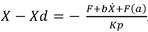
- For instance, the sub-expected pitch angle is obtained according to the expected pitch angle corresponding to the attitude. For instance, the angle range required to be adjusted may be calculated according to the expected pitch angle and the initial pitch angle; subsequently, the angle range is divided by the maximum angle that can be adjusted in the control cycle to obtain each adjusting angle; and finally, the sub-expected pitch angle of this adjustment is calculated according to this adjusting angle and corresponding number of adjustments and the initial pitch angle.
- In some embodiments, the parameter F(a) in the above formula can be obtained by the fitting of the results of actual engineering measurements (that is, numerical solution can be used to approximate corresponding relation equation). A relevant device may also be mounted on the photographic equipment to measure the force generated by the photographic equipment at the acceleration a. Or the parameter may be obtained by calculation through F(a)=ma, in which m refers to the mass of the photographic equipment.
- In some embodiments, the step of determining the expected pitch angle of the photographic equipment according to the attitude information of the mobile device in S211 may include: determining the attitude of the mobile device according to the attitude information; and determining the expected pitch angle of the mobile device at the attitude according to the corresponding relation between the expected pitch angle and the attitude.
- For instance, the sub-expected pitch angle corresponding to each control cycle is calculated according to the determined pitch angle at the attitude. The sub-expected pitch angle is relevant to the maximum angle of the motor that can be adjusted in the current control cycle. The expected pitch angle is relevant to the attitude of the car.
- For instance, the photographic equipment is a camera. The initial pitch angle of the camera is 30°; the expected pitch angle of the car at the current attitude, obtained according to the attitude data of the car, is 40°; and the control cycle of each adjustment is 100ms. According to the motor performance, the maximum intersection angle increment of the camera in one control cycle is 0.5°, so the obtained number of control steps is 20 (namely (40°-30°)/ 0.5°=20), and the 20 here is the obtained number of adjustments. The sub-expected pitch angles obtained after subdivision are respectively: 30.5°, 31°, 31.5°, 32°, 32.5°, 33°...40°.
- In each adjustment, the sub-expected pitch angle corresponding to this adjustment, obtained after subdivision, is taken as the target pitch angle of this adjustment. For instance, when the serial number is 3, the sub-expected pitch angle is 31.5°, namely the target pitch angle of the current motor in the third control cycle is 31.5°, and the pitch angle of the current camera acquired by the angle sensor is marked as angle_real. A deviation angle is obtained by subtracting the sub-expected pitch angle and the current pitch angle, and then the deviation angle is inputted into a controller. The sub-driving force required for rotating the photographic equipment to the position of the sub-expected pitch angle may be obtained according to the force and displacement conversion algorithm (the computing formulas of two forces as described below) on the basis of the deviation angle. The sub-driving force drives the photographic equipment to move to corresponding position of the sub-expected pitch angle. The angle between the photographic equipment and the level ground can be rotated to 40° after repeating the example for 20 times, that is, the photographic equipment can be basically rotated to the expected pitch angle 40° after 20 adjustments.
- In some embodiments, the step of determining the current pitch angle of the photographic equipment may include: detecting the current angular displacement and angular velocity information of the photographic equipment; and determining the current pitch angle according to the angular displacement and angular velocity information.
- As shown in
FIG. 3A which is a schematic diagram illustrating the process of adjusting the pitch angle in some embodiments of the present disclosure, the process of adjusting the pitch angle may include: S301: parameter initialization; S311: reading of equipment parameters; S321: Kalman filtering; S331: analog-to-digital conversion; S341: PID control; and S351: end of pitch angle adjustment. - For instance, the parameter initialization includes the initialization of the mobile device (e.g., the car), the photographic equipment, etc. The reading of the equipment parameters includes: reading attitude data information of the car, reading the initial pitch angle of the photographic equipment, etc.
- For instance, in the step S321, information relevant to the acquired pitch angle is subjected to Kalman filtering, and then the current pitch angle of the photographic equipment is obtained; the obtained current pitch angle is subjected to analog-to-digital conversion; and a digital signal obtained after conversion is taken as an input signal of PID control.
- For instance, the PID control in the step S341 may produce a driving force according to the input expected pitch angle and the feedback or acquired current pitch angle. Subsequently, the driving force is adopted to drive the motor to adjust the pitch angle of the photographic equipment. Moreover, for instance, after the end of this control cycle, the angular displacement offset (namely the difference between the pitch angle after this adjustment and the expected pitch angle) is calculated. If the angular displacement offset is greater than a certain threshold, at least one control cycle must be started again for adjustment. If the angular displacement offset is less than or equal to the set threshold, the adjustment of the pitch angle of the photographic equipment is ended.
-
FIG. 3B is a flowchart illustrating the process of adjusting the pitch angle of the camera by adoption of multiple control cycles in some embodiments of the present disclosure. For instance, the process of adjusting the pitch angle of the camera by adoption of multiple control cycles may include: S302: initializing parameters; S312: setting the expected pitch angle of the camera; S322: dividing the expected pitch angle into a plurality of sub-expected pitch angles according to the control cycle and the maximum intersection angle in the control cycle; S332: inputting one sub-expected pitch angle obtained after subdivision; S342: obtaining corresponding sub-driving force by adoption of force and displacement conversion algorithm; S352: outputting the sub-driving force for driving a motor; S362: driving the motor to rotate to an expected position; S372: determining whether the adjustment processes based on all the sub-expected pitch angle have been executed, executing the step S392 if the adjustment processes of all the sub-expected pitch angles have been executed, and executing the step S382 if not; S382: feeding back the acquired current pitch angle, and returning to the step S342; and S392: ending the adjustment process of the pitch angle. - For instance, the process of dividing the expected pitch angle into the plurality of pitch angles in the step S322 may refer to the method provided by the above embodiment. The sequentially obtained sub-expected pitch angles will be inputted in the step S332 until the step S342 is executed, and then corresponding sub-driving force will be obtained in the step S342 according to one of the above computing formulas of the two sub-driving forces on the basis of the input sub-expected pitch angle and the current expected pitch angle of the photographic equipment obtained by feedback. The driver is driven by the sub-driving force in the step S362. Whether the adjustment processes of all the sub-expected pitch angles have been executed will be determined according to the set serial number in the step S372. For instance, a flag is set to store the serial number, and the serial number stored on the flag will be automatically added by one after the angle adjustment of one control cycle is executed. The number of cycles is the same with the number of the sub-expected pitch angles. For instance, in the above step S382, the current pitch angle data may be acquired by adoption of an angular displacement sensor. The embodiments described in connection with
Fig. 3A andFig. 3B are to be considered merely as examples suitable for understanding the invention. -
FIG. 4 illustrates adevice 400 for stabilizing photographic equipment on a mobile device, provided by at least one embodiment of the present disclosure. Thedevice 400 for stabilizing the photographic equipment on the mobile device may comprise: astabilizer 401, acontroller 402, adriver 403 and asensor 404. The photographic equipment is placed on thestabilizer 401. Thesensor 404 acquires the pitch angle of thestabilizer 401. Thecontroller 402 is configured to: acquire attitude information of the mobile device; determine the expected pitch angle of the photographic equipment according to the attitude information of the mobile device; and determine the driving force according to the expected pitch angle. Thedriver 403 is configured to adjust the pitch angle of thestabilizer 401 according to the driving force. - In some embodiments, the pitch angle of the
stabilizer 401 is taken as the pitch angle of the photographic equipment. This is merely for the convenience of describing the technical proposal, and it can be deduced that when the photographic equipment is not placed in parallel on corresponding plane of thestabilizer 401 but the placing orientations of both are relatively fixed, in order to obtain the pitch angle of the photographic equipment according to the pitch angle of the stabilizer, angle conversion is required so that the pitch angle of the photographic equipment can be finally obtained according to the angle of thestabilizer 401. However, the pitch angle of the photographic equipment obtained on the basis of the conventional mathematical conversion shall also fall within the scope of protection of the embodiment of the present disclosure. - For instance, the
sensor 404 may be mounted on thestabilizer 401, so that the angular displacement sensor can measure the pitch angle of thestabilizer 401. Moreover, for instance, thesensor 404 may be a gyroscope. - In some embodiments, the
stabilizer 401 may be a single-degree-of-freedom camera stabilization mechanism. For instance, thestabilizer 401 is a tripod head, in which the tripod head is configured to have single degree of freedom in the pitch direction. - In some embodiments, the
controller 402 includes one ormore processors 4021. For instance, the processor may be a microcontroller unit (MCU). For instance, the controller may be connected with thedriver 403 through an output port of the MCU. Moreover, for instance, the minimum system of the MCU adopts ATmega16 MCU, and its minimum system circuit includes an external clock circuit, a reset circuit, an ISP port of a USBASP download line, etc. - In some embodiments, the processor may also be a central processing unit (CPU), a field programmable gate array (FPGA), an application-specific integrated circuit (ASIC), a digital signal processor (DSP), etc.
- In some embodiments, the processor is further connected with a
memory 4022, and computer instructions are stored in thememory 4022. - In some embodiments, the
driver 403 may be a motor such as a stepper motor or a servo motor. The servo motor may be an AC motor and may also be a DC motor. Based on the motor type, direct current supply or alternating current supply is correspondingly adopted to supply power for thedriver 403. - For instance, the
driver 403 may adopt a steering gear. - The
controller 402 is further configured to: read the initial pitch angle of the photographic equipment; calculate the number of adjustments according to the expected pitch angle and the initial pitch angle; and acquire the sub-driving force of each adjustment according to the number of adjustments, the expected pitch angle and the acceleration information. - For instance, the
controller 402 adopts wired or wireless means to receive a pitch angle signal, relevant to the photographic equipment, acquired by theangular displacement sensor 404. Thecontroller 402 may perform filtering in the process of reading the pitch angle signal. - The
controller 402 is further configured to: determine the sub-expected pitch angle of each adjustment according to the serial number of each adjustment; determine the current pitch angle of the photographic equipment; and calculate the sub-driving force of each adjustment according to the sub-expected pitch angle, the current pitch angle and the acceleration information. - The
controller 402 is further configured to: calculate the sub-driving force according to
- The
controller 402 is further configured to: acquire the acceleration a of the mobile device in the vertical direction; and calculate the sub-driving force according to X -
- In some embodiments, the parameter F(a) in the above formula must be obtained by the fitting of the results of actual engineering measurements (that is, numerical solution can be used to approximate corresponding relation equation). A relevant device may also be mounted on the photographic equipment to measure the force generated by the photographic equipment at the acceleration a. Or the parameter may be obtained by calculation through F(a)=ma, in which m refers to the mass of the photographic equipment.
-
FIGS. 5A and 5B are comparison diagrams illustrating the difference in shooting range of the photographic equipment before and after the adoption of the device for stabilizing the photographic equipment on the mobile device provided by one embodiment of the present disclosure.FIG. 5A is a schematic diagram illustrating the shooting range of a camera not adopting the angle adjustment method provided by the present disclosure, and as can be seen from the figure, as the pitch angle between the camera and the ground is not adjusted in time, the shooting range of the photographic equipment is limited. As shown inFIG. 5B , after the pitch angle adjustment in the embodiment of the present disclosure, the shooting range of the camera has increased a lot. - The control method of camera stabilization provided by the embodiment of the present disclosure simplifies the complex multiple-degree-of-freedom control system according to the characteristic that, during car driving, an image outputted by a smart rearview mirror has high requirement on the stabilization in the pitch direction and has low requirement on the stabilization in the roll and yaw directions. The single-degree-of-freedom control method adopting PID control achieves good effect of stable image output.
- For instance, the cost can be greatly reduced by adopting the acceleration in the vertical direction, provided by the angular displacement sensor in combination with the CAN bus of the car, as feedback input of the controller. That is to say, the embodiment of the present disclosure can actively adjust the camera angle to reach reasonable rearview range according to the driver's viewing angle requirement on the smart rearview mirror.
- The embodiment of the present disclosure further provides a computer readable storage medium, and computer instructions are stored thereon. When the computer instructions are executed by a processor, one or more steps of the following operations are executed: acquiring attitude information of the mobile device; determining the expected pitch angle of the photographic equipment according to the attitude information of the mobile device; and determining the driving force according to the expected pitch angle.
- The embodiment of the present disclosure further provides an electronic product, which comprises one or more processors. The processor is configured to run the computer instructions so as to execute one or more steps of the following operations: acquiring attitude information of the mobile device; determining the expected pitch angle of the photographic equipment according to the attitude information of the mobile device; and determining the driving force according to the expected pitch angle.
- For instance, the computer readable storage medium may be implemented by any of a variety of volatile or nonvolatile storage devices, or a combination thereof, e.g., a static random access memory (SRAM), an electrically erasable programmable read only memory (EEPROM), an erasable programmable read only memory (EPROM), a programmable read only memory (PROM), a read only memory (ROM), a magnetic memory, a flash memory, a magnetic disk or an optical disk.
- For instance, the processor may be a logical computing device having data processing capability and/or program execution capability such as a CPU, an FPGA, an MCU, a DSP or an ASIC.
- For instance, the computer instructions include one or more processor operations defined by an instruction set architecture corresponding to the processor. These computer instructions may be logically included and represented by one or more computer programs.
- The accompanying drawings in the embodiment of the present disclosure only involve the structures relevant to the embodiments of the present disclosure, and other structures may refer to the conventional design. The embodiments of the present disclosure and the characteristics in the embodiments may be mutually combined without conflict.
- The foregoing is only the preferred embodiments of the present invention and not intended to limit the scope of protection of the present invention. Therefore, the scope of protection of the present invention shall be defined by the appended claims.
Claims (9)
- A method for stabilizing photographic equipment on a mobile device, comprising:acquiring attitude information of the mobile device (201);determining an expected pitch angle of the photographic equipment according to the attitude information of the mobile device (211), the expected pitch angle is an angle relative to ground,determining a driving force according to the expected pitch angle (221); andadjusting a pitch angle of the photographic equipment by use of the driving force (231),wherein determining the driving force according to the expected pitch angle includes:reading an initial pitch angle of the photographic equipment;calculating a number of adjustments according to the expected pitch angle and the initial pitch angle; andacquiring a sub-driving force of each adjustment according to the number of adjustments and the expected pitch angle;wherein acquiring the sub-driving force of each adjustment according to the number of adjustments and the expected pitch angle includes:determining a sub-expected pitch angle of each adjustment according to a serial number of each adjustment;determining a current pitch angle of the photographic equipment; andcalculating the sub-driving force of each adjustment according to the sub-expected pitch angle and the current pitch angle;characterized in that:
in a case where a road surface on which the mobile device travels is relatively flat, calculating the sub-driving force of each adjustment according to the sub-expected pitch angle and the current pitch angle includes:calculating the sub-driving force according to in a case where the road surface on which the mobile device travels is bumpy, calculating the sub-driving force of each adjustment according to the sub-expected pitch angle and the current pitch angle includes:acquiring an acceleration a of the mobile device in a vertical direction; andcalculating the sub-driving force according to
- The method for stabilizing the photographic equipment on the mobile device according to claim 1, whereinthe mobile device includes a motor vehicle;the attitude information represents an attitude of the motor vehicle; and the attitude includes at least one selected from the group consisting of uphill, downhill, flat ground, being forward and being backward.
- The method for stabilizing the photographic equipment on the mobile device according to claim 1 or 2, wherein
determining the current pitch angle of the photographic equipment includes:- detecting current angular displacement and angular velocity information of the photographic equipment; and- determining the current pitch angle according to the angular displacement and angular velocity information. - The method for stabilizing the photographic equipment on the mobile device according to any one of claims 1 to 3, wherein
determining the expected pitch angle of the photographic equipment according to the attitude information of the mobile device includes:- determining the attitude of the mobile device according to the attitude information; and- determining the expected pitch angle of the mobile device at the attitude according to a corresponding relation between the expected pitch angle and the attitude. - A device for stabilizing photographic equipment on a mobile device, comprising: a stabilizer (401), a controller (402), a driver (403) and a sensor (404), whereinthe stabilizer (401) is configured to carry the photographic equipment;the sensor (404) is configured to acquire a pitch angle of the stabilizer (401);the controller (402) is configured to:- acquire attitude information of the mobile device;- determine an expected pitch angle of the photographic equipment according to the attitude information of the mobile device, the expected pitch angle is an angle relative to ground; and- determine a driving force according to the expected pitch angle; andthe driver (403) is configured to adjust the pitch angle of the stabilizer (401) according to the driving force;wherein the controller (402) is further configured to:- read an initial pitch angle of the photographic equipment;- calculate a number of adjustments according to the expected pitch angle and the initial pitch angle; and- acquire a sub-driving force of each adjustment according to the number of adjustments and the expected pitch angle;wherein the controller (402) is further configured to:- determine a sub-expected pitch angle of each adjustment according to a serial number of each adjustment;determine a current pitch angle of the photographic equipment; and- calculate the sub-driving force of each adjustment according to the sub-expected pitch angle and the current pitch angle;characterized in that the controller is further configured to:- in a case where a road surface on which the mobile device travels is relatively flat, calculate the sub-driving force according to
 - in a case where the road surface on which the mobile device travels is bumpy, acquire an acceleration a of the mobile device in a vertical direction and calculate the sub-driving force according to
- The device for stabilizing the photographic equipment on the mobile device according to claim 5, wherein the stabilizer (401) includes a tripod head which is configured to have single degree of freedom in a pitch direction.
- The device for stabilizing the photographic equipment on the mobile device according to claim 5 or 6, wherein the driver (403) includes a servo motor; and the controller (402) includes a microcontroller unit (MCU).
- A computer readable storage medium, wherein computer instructions are stored in the computer readable storage medium, and the steps of the method according to any one of claims 1 to 4 are implemented when the computer instructions are executed by a processor.
- An electronic product, comprising one or more processors, wherein the processor is configured to run computer instructions so as to execute the steps of the method according to any one of claims 1 to 4.
Applications Claiming Priority (2)
| Application Number | Priority Date | Filing Date | Title |
|---|---|---|---|
| CN201710514230.3A CN109213211B (en) | 2017-06-29 | 2017-06-29 | Method and device for stabilizing photographic equipment |
| PCT/CN2018/078027 WO2019001000A1 (en) | 2017-06-29 | 2018-03-05 | Method and device for stabilizing imaging apparatus at motorized device, and device |
Publications (3)
| Publication Number | Publication Date |
|---|---|
| EP3647898A1 EP3647898A1 (en) | 2020-05-06 |
| EP3647898A4 EP3647898A4 (en) | 2021-04-07 |
| EP3647898B1 true EP3647898B1 (en) | 2025-05-07 |
Family
ID=64742768
Family Applications (1)
| Application Number | Title | Priority Date | Filing Date |
|---|---|---|---|
| EP18799421.5A Active EP3647898B1 (en) | 2017-06-29 | 2018-03-05 | Method and device for stabilizing imaging apparatus at motorized device, and device |
Country Status (4)
| Country | Link |
|---|---|
| US (1) | US11115592B2 (en) |
| EP (1) | EP3647898B1 (en) |
| CN (1) | CN109213211B (en) |
| WO (1) | WO2019001000A1 (en) |
Families Citing this family (2)
| Publication number | Priority date | Publication date | Assignee | Title |
|---|---|---|---|---|
| DE112020007826T5 (en) * | 2020-12-10 | 2023-09-28 | Google Llc | IMPROVED VIDEO STABILIZATION BASED ON MACHINE LEARNING MODELS |
| CN116708989A (en) * | 2023-05-12 | 2023-09-05 | 北京鉴智科技有限公司 | A control method, device, vehicle and storage medium of a vehicle-mounted camera |
Family Cites Families (21)
| Publication number | Priority date | Publication date | Assignee | Title |
|---|---|---|---|---|
| CN2060537U (en) * | 1989-08-12 | 1990-08-15 | 陕西省地质矿产局测绘队 | An automatic control platform for aerial remote sensing and camera |
| JPH09154057A (en) * | 1995-11-29 | 1997-06-10 | Tokimec Inc | Attitude stabilizing device |
| JP4137028B2 (en) | 2004-08-19 | 2008-08-20 | 日本航空電子工業株式会社 | Camera stabilizer mounting error acquisition method and camera stabilizer to which this method is applied |
| JP2012156909A (en) * | 2011-01-28 | 2012-08-16 | Nippon Seiki Co Ltd | Rear side imaging apparatus |
| CN202295294U (en) | 2011-09-15 | 2012-07-04 | 深圳市大疆创新科技有限公司 | Cradle head for unmanned aerial vehicle |
| CN102588718B (en) * | 2012-01-12 | 2014-06-04 | 佛山科学技术学院 | Electric panoramic tripod head with Bluetooth control function and control method |
| CN202660187U (en) * | 2012-06-20 | 2013-01-09 | 李林桐 | Photography platform |
| DE102013201379B4 (en) * | 2013-01-29 | 2020-12-10 | Robert Bosch Gmbh | Motorcycle with a camera system |
| CN103359001B (en) * | 2013-08-02 | 2016-04-20 | 北京汽车股份有限公司 | A kind of outside rear-view mirror fine adjustment system and automobile |
| GB2517788B (en) * | 2013-09-03 | 2016-06-08 | Jaguar Land Rover Ltd | Water depth estimation apparatus and method |
| CN106029501B (en) * | 2014-12-23 | 2019-05-14 | 深圳市大疆灵眸科技有限公司 | UAV panoramic imaging |
| CN204997688U (en) * | 2015-05-22 | 2016-01-27 | 深圳市大疆创新科技有限公司 | Moving device |
| CN105045293B (en) * | 2015-05-27 | 2018-05-08 | 深圳一电航空技术有限公司 | Cloud platform control method, outer carrier control method and holder |
| CN105045018B (en) | 2015-07-30 | 2017-09-01 | 极翼机器人(上海)有限公司 | Head |
| CN105116926B (en) * | 2015-08-20 | 2018-05-04 | 深圳一电航空技术有限公司 | Cloud platform control method and device |
| CN105522968A (en) * | 2015-12-21 | 2016-04-27 | 浙江大学 | Automatic adjustment system for automobile rearview mirrors |
| CN105716584A (en) * | 2016-03-31 | 2016-06-29 | 江苏鸿鹄无人机应用科技有限公司 | Oblique photographic camera provided with self-stabilizing system and control method of oblique photographic camera |
| CN205707401U (en) | 2016-04-15 | 2016-11-23 | 山东工商学院 | One is taken photo by plane calibrating installation and aerial photography aircraft |
| CN105933615A (en) * | 2016-07-04 | 2016-09-07 | 北方民族大学 | Unmanned aerial vehicle based image acquisition system, image acquisition method and unmanned aerial vehicle |
| CN106716284B (en) * | 2016-08-31 | 2019-09-24 | 深圳市大疆创新科技有限公司 | Control method, device and system, aircraft, carrier and manipulation device |
| CN106740539A (en) * | 2016-12-30 | 2017-05-31 | 深圳市保千里电子有限公司 | A kind of method and system of the anti-camera-shake based on drive recorder |
-
2017
- 2017-06-29 CN CN201710514230.3A patent/CN109213211B/en active Active
-
2018
- 2018-03-05 WO PCT/CN2018/078027 patent/WO2019001000A1/en not_active Ceased
- 2018-03-05 EP EP18799421.5A patent/EP3647898B1/en active Active
- 2018-03-05 US US16/303,328 patent/US11115592B2/en active Active
Also Published As
| Publication number | Publication date |
|---|---|
| WO2019001000A1 (en) | 2019-01-03 |
| EP3647898A1 (en) | 2020-05-06 |
| CN109213211A (en) | 2019-01-15 |
| CN109213211B (en) | 2021-09-21 |
| US11115592B2 (en) | 2021-09-07 |
| US20190246023A1 (en) | 2019-08-08 |
| EP3647898A4 (en) | 2021-04-07 |
Similar Documents
| Publication | Publication Date | Title |
|---|---|---|
| CN110057352B (en) | A kind of camera attitude angle determination method and device | |
| CN109767475B (en) | A method and system for calibrating external parameters of a sensor | |
| US10836395B2 (en) | Efficient optimal control with dynamic model for autonomous vehicle | |
| Wang et al. | Online high-precision probabilistic localization of robotic fish using visual and inertial cues | |
| US11156905B2 (en) | Control method for gimbal, controller, and gimbal | |
| US20220238029A1 (en) | Unmanned aerial vehicle return method and apparatus and unmanned aerial vehicle | |
| CN111976833B (en) | Calibration method, device, device and storage medium for steering wheel parameters | |
| US11669109B2 (en) | Method and apparatus for yaw fusion and aircraft | |
| US20190310658A1 (en) | Unmanned aerial vehicle | |
| US20210165388A1 (en) | Gimbal rotation control method and apparatus, control device, and movable platform | |
| CN110440805A (en) | A kind of fusion method of yaw angle, device and aircraft | |
| CN108932737A (en) | In-vehicle camera pitch angle scaling method and device, electronic equipment and vehicle | |
| CN114954507B (en) | Active trajectory tracking control for autopilot during altitude transitions | |
| CN108700249A (en) | Method for controlling pan-tilt, pan-tilt, control system and movable device | |
| EP3647898B1 (en) | Method and device for stabilizing imaging apparatus at motorized device, and device | |
| CN119618206B (en) | Inertial navigation device and system based on multi-mode data analysis | |
| CN110637266A (en) | The control method of the cloud platform and the cloud platform | |
| CN114641746B (en) | Movable platform and control method and device thereof | |
| JP7673693B2 (en) | Towing vehicle control device, towing vehicle control method, and towing vehicle control program | |
| JP7393987B2 (en) | Map creation device, position estimation device, vehicle control system, map creation method, computer program, and location estimation method | |
| CN115963858A (en) | Unmanned aerial vehicle flight control method, device, equipment and storage medium | |
| CN114167901B (en) | A pan/tilt control method, device, electronic equipment, pod and storage medium | |
| CN114153234B (en) | A pan/tilt control method and device, electronic equipment, storage medium and pod | |
| CN114167902B (en) | PTZ control method, device, control equipment and storage medium | |
| JP6146520B1 (en) | Optical apparatus, moving body, holding position adjusting method, and program |
Legal Events
| Date | Code | Title | Description |
|---|---|---|---|
| STAA | Information on the status of an ep patent application or granted ep patent |
Free format text: STATUS: UNKNOWN |
|
| STAA | Information on the status of an ep patent application or granted ep patent |
Free format text: STATUS: THE INTERNATIONAL PUBLICATION HAS BEEN MADE |
|
| PUAI | Public reference made under article 153(3) epc to a published international application that has entered the european phase |
Free format text: ORIGINAL CODE: 0009012 |
|
| STAA | Information on the status of an ep patent application or granted ep patent |
Free format text: STATUS: REQUEST FOR EXAMINATION WAS MADE |
|
| 17P | Request for examination filed |
Effective date: 20181119 |
|
| AK | Designated contracting states |
Kind code of ref document: A1 Designated state(s): AL AT BE BG CH CY CZ DE DK EE ES FI FR GB GR HR HU IE IS IT LI LT LU LV MC MK MT NL NO PL PT RO RS SE SI SK SM TR |
|
| AX | Request for extension of the european patent |
Extension state: BA ME |
|
| DAV | Request for validation of the european patent (deleted) | ||
| DAX | Request for extension of the european patent (deleted) | ||
| R17P | Request for examination filed (corrected) |
Effective date: 20181119 |
|
| REG | Reference to a national code |
Ref legal event code: R079 Ipc: G03B0017560000 Ref country code: DE Ref legal event code: R079 Ref document number: 602018081765 Country of ref document: DE Free format text: PREVIOUS MAIN CLASS: G05D0003200000 Ipc: G03B0017560000 |
|
| A4 | Supplementary search report drawn up and despatched |
Effective date: 20210311 |
|
| RIC1 | Information provided on ipc code assigned before grant |
Ipc: G05D 1/00 20060101ALI20210304BHEP Ipc: G05D 3/12 20060101ALI20210304BHEP Ipc: B60R 11/04 20060101ALI20210304BHEP Ipc: G05D 3/20 20060101ALI20210304BHEP Ipc: G03B 17/56 20210101AFI20210304BHEP Ipc: H04N 5/232 20060101ALI20210304BHEP Ipc: B60R 11/00 20060101ALI20210304BHEP |
|
| STAA | Information on the status of an ep patent application or granted ep patent |
Free format text: STATUS: EXAMINATION IS IN PROGRESS |
|
| 17Q | First examination report despatched |
Effective date: 20230209 |
|
| GRAP | Despatch of communication of intention to grant a patent |
Free format text: ORIGINAL CODE: EPIDOSNIGR1 |
|
| STAA | Information on the status of an ep patent application or granted ep patent |
Free format text: STATUS: GRANT OF PATENT IS INTENDED |
|
| RIC1 | Information provided on ipc code assigned before grant |
Ipc: G05D 3/20 20060101ALI20241129BHEP Ipc: G05D 3/12 20060101ALI20241129BHEP Ipc: H04N 23/68 20230101ALI20241129BHEP Ipc: B60R 11/04 20060101ALI20241129BHEP Ipc: G05D 1/00 20060101ALI20241129BHEP Ipc: B60R 11/00 20060101ALI20241129BHEP Ipc: G03B 17/56 20060101AFI20241129BHEP |
|
| INTG | Intention to grant announced |
Effective date: 20241213 |
|
| GRAS | Grant fee paid |
Free format text: ORIGINAL CODE: EPIDOSNIGR3 |
|
| GRAA | (expected) grant |
Free format text: ORIGINAL CODE: 0009210 |
|
| STAA | Information on the status of an ep patent application or granted ep patent |
Free format text: STATUS: THE PATENT HAS BEEN GRANTED |
|
| AK | Designated contracting states |
Kind code of ref document: B1 Designated state(s): AL AT BE BG CH CY CZ DE DK EE ES FI FR GB GR HR HU IE IS IT LI LT LU LV MC MK MT NL NO PL PT RO RS SE SI SK SM TR |
|
| REG | Reference to a national code |
Ref country code: GB Ref legal event code: FG4D |
|
| REG | Reference to a national code |
Ref country code: CH Ref legal event code: EP |
|
| REG | Reference to a national code |
Ref country code: DE Ref legal event code: R096 Ref document number: 602018081765 Country of ref document: DE |
|
| REG | Reference to a national code |
Ref country code: IE Ref legal event code: FG4D |
|
| REG | Reference to a national code |
Ref country code: NL Ref legal event code: MP Effective date: 20250507 |
|
| PG25 | Lapsed in a contracting state [announced via postgrant information from national office to epo] |
Ref country code: PT Free format text: LAPSE BECAUSE OF FAILURE TO SUBMIT A TRANSLATION OF THE DESCRIPTION OR TO PAY THE FEE WITHIN THE PRESCRIBED TIME-LIMIT Effective date: 20250908 Ref country code: ES Free format text: LAPSE BECAUSE OF FAILURE TO SUBMIT A TRANSLATION OF THE DESCRIPTION OR TO PAY THE FEE WITHIN THE PRESCRIBED TIME-LIMIT Effective date: 20250507 Ref country code: FI Free format text: LAPSE BECAUSE OF FAILURE TO SUBMIT A TRANSLATION OF THE DESCRIPTION OR TO PAY THE FEE WITHIN THE PRESCRIBED TIME-LIMIT Effective date: 20250507 |
|
| REG | Reference to a national code |
Ref country code: LT Ref legal event code: MG9D |
|
| PG25 | Lapsed in a contracting state [announced via postgrant information from national office to epo] |
Ref country code: GR Free format text: LAPSE BECAUSE OF FAILURE TO SUBMIT A TRANSLATION OF THE DESCRIPTION OR TO PAY THE FEE WITHIN THE PRESCRIBED TIME-LIMIT Effective date: 20250808 Ref country code: NO Free format text: LAPSE BECAUSE OF FAILURE TO SUBMIT A TRANSLATION OF THE DESCRIPTION OR TO PAY THE FEE WITHIN THE PRESCRIBED TIME-LIMIT Effective date: 20250807 |
|
| PG25 | Lapsed in a contracting state [announced via postgrant information from national office to epo] |
Ref country code: NL Free format text: LAPSE BECAUSE OF FAILURE TO SUBMIT A TRANSLATION OF THE DESCRIPTION OR TO PAY THE FEE WITHIN THE PRESCRIBED TIME-LIMIT Effective date: 20250507 Ref country code: PL Free format text: LAPSE BECAUSE OF FAILURE TO SUBMIT A TRANSLATION OF THE DESCRIPTION OR TO PAY THE FEE WITHIN THE PRESCRIBED TIME-LIMIT Effective date: 20250507 |
|
| REG | Reference to a national code |
Ref country code: AT Ref legal event code: MK05 Ref document number: 1793118 Country of ref document: AT Kind code of ref document: T Effective date: 20250507 |
|
| PG25 | Lapsed in a contracting state [announced via postgrant information from national office to epo] |
Ref country code: BG Free format text: LAPSE BECAUSE OF FAILURE TO SUBMIT A TRANSLATION OF THE DESCRIPTION OR TO PAY THE FEE WITHIN THE PRESCRIBED TIME-LIMIT Effective date: 20250507 |
|
| PG25 | Lapsed in a contracting state [announced via postgrant information from national office to epo] |
Ref country code: HR Free format text: LAPSE BECAUSE OF FAILURE TO SUBMIT A TRANSLATION OF THE DESCRIPTION OR TO PAY THE FEE WITHIN THE PRESCRIBED TIME-LIMIT Effective date: 20250507 |
|
| PG25 | Lapsed in a contracting state [announced via postgrant information from national office to epo] |
Ref country code: AT Free format text: LAPSE BECAUSE OF FAILURE TO SUBMIT A TRANSLATION OF THE DESCRIPTION OR TO PAY THE FEE WITHIN THE PRESCRIBED TIME-LIMIT Effective date: 20250507 |
|
| PG25 | Lapsed in a contracting state [announced via postgrant information from national office to epo] |
Ref country code: RS Free format text: LAPSE BECAUSE OF FAILURE TO SUBMIT A TRANSLATION OF THE DESCRIPTION OR TO PAY THE FEE WITHIN THE PRESCRIBED TIME-LIMIT Effective date: 20250807 |
|
| PG25 | Lapsed in a contracting state [announced via postgrant information from national office to epo] |
Ref country code: IS Free format text: LAPSE BECAUSE OF FAILURE TO SUBMIT A TRANSLATION OF THE DESCRIPTION OR TO PAY THE FEE WITHIN THE PRESCRIBED TIME-LIMIT Effective date: 20250907 |
|
| PG25 | Lapsed in a contracting state [announced via postgrant information from national office to epo] |
Ref country code: LV Free format text: LAPSE BECAUSE OF FAILURE TO SUBMIT A TRANSLATION OF THE DESCRIPTION OR TO PAY THE FEE WITHIN THE PRESCRIBED TIME-LIMIT Effective date: 20250507 |
|
| PG25 | Lapsed in a contracting state [announced via postgrant information from national office to epo] |
Ref country code: DK Free format text: LAPSE BECAUSE OF FAILURE TO SUBMIT A TRANSLATION OF THE DESCRIPTION OR TO PAY THE FEE WITHIN THE PRESCRIBED TIME-LIMIT Effective date: 20250507 Ref country code: SM Free format text: LAPSE BECAUSE OF FAILURE TO SUBMIT A TRANSLATION OF THE DESCRIPTION OR TO PAY THE FEE WITHIN THE PRESCRIBED TIME-LIMIT Effective date: 20250507 |
|
| PG25 | Lapsed in a contracting state [announced via postgrant information from national office to epo] |
Ref country code: CZ Free format text: LAPSE BECAUSE OF FAILURE TO SUBMIT A TRANSLATION OF THE DESCRIPTION OR TO PAY THE FEE WITHIN THE PRESCRIBED TIME-LIMIT Effective date: 20250507 |
|
| PG25 | Lapsed in a contracting state [announced via postgrant information from national office to epo] |
Ref country code: EE Free format text: LAPSE BECAUSE OF FAILURE TO SUBMIT A TRANSLATION OF THE DESCRIPTION OR TO PAY THE FEE WITHIN THE PRESCRIBED TIME-LIMIT Effective date: 20250507 |
|
| PG25 | Lapsed in a contracting state [announced via postgrant information from national office to epo] |
Ref country code: SK Free format text: LAPSE BECAUSE OF FAILURE TO SUBMIT A TRANSLATION OF THE DESCRIPTION OR TO PAY THE FEE WITHIN THE PRESCRIBED TIME-LIMIT Effective date: 20250507 Ref country code: RO Free format text: LAPSE BECAUSE OF FAILURE TO SUBMIT A TRANSLATION OF THE DESCRIPTION OR TO PAY THE FEE WITHIN THE PRESCRIBED TIME-LIMIT Effective date: 20250507 |
|
| PG25 | Lapsed in a contracting state [announced via postgrant information from national office to epo] |
Ref country code: IT Free format text: LAPSE BECAUSE OF FAILURE TO SUBMIT A TRANSLATION OF THE DESCRIPTION OR TO PAY THE FEE WITHIN THE PRESCRIBED TIME-LIMIT Effective date: 20250507 |
|
| REG | Reference to a national code |
Ref country code: DE Ref legal event code: R097 Ref document number: 602018081765 Country of ref document: DE |
|
| PLBE | No opposition filed within time limit |
Free format text: ORIGINAL CODE: 0009261 |
|
| STAA | Information on the status of an ep patent application or granted ep patent |
Free format text: STATUS: NO OPPOSITION FILED WITHIN TIME LIMIT |
|
| REG | Reference to a national code |
Ref country code: CH Ref legal event code: L10 Free format text: ST27 STATUS EVENT CODE: U-0-0-L10-L00 (AS PROVIDED BY THE NATIONAL OFFICE) Effective date: 20260318 |
|
| PGFP | Annual fee paid to national office [announced via postgrant information from national office to epo] |
Ref country code: GB Payment date: 20260324 Year of fee payment: 9 |
|
| PGFP | Annual fee paid to national office [announced via postgrant information from national office to epo] |
Ref country code: DE Payment date: 20260319 Year of fee payment: 9 |
|
| 26N | No opposition filed |
Effective date: 20260210 |