EP3647818A1 - Fish school finding device, fish length measuring device, fish school finding method, and fish school finding program - Google Patents
Fish school finding device, fish length measuring device, fish school finding method, and fish school finding program Download PDFInfo
- Publication number
- EP3647818A1 EP3647818A1 EP18822651.8A EP18822651A EP3647818A1 EP 3647818 A1 EP3647818 A1 EP 3647818A1 EP 18822651 A EP18822651 A EP 18822651A EP 3647818 A1 EP3647818 A1 EP 3647818A1
- Authority
- EP
- European Patent Office
- Prior art keywords
- fish
- measurement area
- individual
- fish school
- school
- Prior art date
- Legal status (The legal status is an assumption and is not a legal conclusion. Google has not performed a legal analysis and makes no representation as to the accuracy of the status listed.)
- Granted
Links
Images






Classifications
-
- G—PHYSICS
- G01—MEASURING; TESTING
- G01S—RADIO DIRECTION-FINDING; RADIO NAVIGATION; DETERMINING DISTANCE OR VELOCITY BY USE OF RADIO WAVES; LOCATING OR PRESENCE-DETECTING BY USE OF THE REFLECTION OR RERADIATION OF RADIO WAVES; ANALOGOUS ARRANGEMENTS USING OTHER WAVES
- G01S15/00—Systems using the reflection or reradiation of acoustic waves, e.g. sonar systems
- G01S15/88—Sonar systems specially adapted for specific applications
- G01S15/89—Sonar systems specially adapted for specific applications for mapping or imaging
-
- G—PHYSICS
- G01—MEASURING; TESTING
- G01S—RADIO DIRECTION-FINDING; RADIO NAVIGATION; DETERMINING DISTANCE OR VELOCITY BY USE OF RADIO WAVES; LOCATING OR PRESENCE-DETECTING BY USE OF THE REFLECTION OR RERADIATION OF RADIO WAVES; ANALOGOUS ARRANGEMENTS USING OTHER WAVES
- G01S15/00—Systems using the reflection or reradiation of acoustic waves, e.g. sonar systems
- G01S15/88—Sonar systems specially adapted for specific applications
- G01S15/96—Sonar systems specially adapted for specific applications for locating fish
-
- G—PHYSICS
- G01—MEASURING; TESTING
- G01S—RADIO DIRECTION-FINDING; RADIO NAVIGATION; DETERMINING DISTANCE OR VELOCITY BY USE OF RADIO WAVES; LOCATING OR PRESENCE-DETECTING BY USE OF THE REFLECTION OR RERADIATION OF RADIO WAVES; ANALOGOUS ARRANGEMENTS USING OTHER WAVES
- G01S7/00—Details of systems according to groups G01S13/00, G01S15/00, G01S17/00
- G01S7/52—Details of systems according to groups G01S13/00, G01S15/00, G01S17/00 of systems according to group G01S15/00
- G01S7/539—Details of systems according to groups G01S13/00, G01S15/00, G01S17/00 of systems according to group G01S15/00 using analysis of echo signal for target characterisation; Target signature; Target cross-section
-
- G—PHYSICS
- G01—MEASURING; TESTING
- G01S—RADIO DIRECTION-FINDING; RADIO NAVIGATION; DETERMINING DISTANCE OR VELOCITY BY USE OF RADIO WAVES; LOCATING OR PRESENCE-DETECTING BY USE OF THE REFLECTION OR RERADIATION OF RADIO WAVES; ANALOGOUS ARRANGEMENTS USING OTHER WAVES
- G01S7/00—Details of systems according to groups G01S13/00, G01S15/00, G01S17/00
- G01S7/52—Details of systems according to groups G01S13/00, G01S15/00, G01S17/00 of systems according to group G01S15/00
- G01S7/56—Display arrangements
- G01S7/62—Cathode-ray tube displays
- G01S7/6263—Cathode-ray tube displays in which different colours are used
-
- G—PHYSICS
- G01—MEASURING; TESTING
- G01S—RADIO DIRECTION-FINDING; RADIO NAVIGATION; DETERMINING DISTANCE OR VELOCITY BY USE OF RADIO WAVES; LOCATING OR PRESENCE-DETECTING BY USE OF THE REFLECTION OR RERADIATION OF RADIO WAVES; ANALOGOUS ARRANGEMENTS USING OTHER WAVES
- G01S7/00—Details of systems according to groups G01S13/00, G01S15/00, G01S17/00
- G01S7/52—Details of systems according to groups G01S13/00, G01S15/00, G01S17/00 of systems according to group G01S15/00
- G01S7/56—Display arrangements
- G01S7/62—Cathode-ray tube displays
- G01S7/6272—Cathode-ray tube displays producing cursor lines and indicia by electronic means
-
- G—PHYSICS
- G06—COMPUTING OR CALCULATING; COUNTING
- G06T—IMAGE DATA PROCESSING OR GENERATION, IN GENERAL
- G06T7/00—Image analysis
- G06T7/10—Segmentation; Edge detection
- G06T7/11—Region-based segmentation
-
- G—PHYSICS
- G06—COMPUTING OR CALCULATING; COUNTING
- G06T—IMAGE DATA PROCESSING OR GENERATION, IN GENERAL
- G06T7/00—Image analysis
- G06T7/10—Segmentation; Edge detection
- G06T7/187—Segmentation; Edge detection involving region growing; involving region merging; involving connected component labelling
-
- G—PHYSICS
- G06—COMPUTING OR CALCULATING; COUNTING
- G06T—IMAGE DATA PROCESSING OR GENERATION, IN GENERAL
- G06T2207/00—Indexing scheme for image analysis or image enhancement
- G06T2207/30—Subject of image; Context of image processing
- G06T2207/30242—Counting objects in image
Definitions
- the present invention relates to a fish school finding device, a fish length measuring device, a fish school finding method, and a fish school finding program, for transmitting an ultrasonic wave into water and detect an object like fish school from the echo signal.
- a fish school finding device for transmitting ultrasonic waves into water and detecting fish school from an echo signal of the ultrasonic waves.
- a fish school finding device for example, as shown in Patent Document 1, there is a fish school finding device that extracts fish school with high accuracy by binarizing data generated based on an echo signal with reference to a signal level.
- each fishing vessel can surely catch only fish of a target fish species or fish length.
- An object of the present invention is to automatically set the measurement area of the fish species or the measurement area of the fish length, or the like.
- the present invention comprises: an individual fish detecting module configured to detect an individual fish from echo information obtained from ultrasonic waves transmitted in a depth direction at predetermined time intervals; an individual fish number calculating module configured to calculate a number of the individual fish for each of a plurality of two-dimensionally arrayed sections consisting of the depth direction and a time axis direction; a reference section detecting module configured to detect a reference section based on the number of the individual fish; and a measurement area setting module configured to set a measurement area based on the reference section.
- the number of individual fish detected from the original echo is calculated as the number of individual fish for each of a plurality of two-dimensionally arrayed sections.
- the measurement area is automatically set based on the number of individual fish calculated for each section.
- the measurement area of the fish species, the measurement area of the fish length or the like can be automatically set.
- the configuration of the fish school finding device according to the first embodiment of the present invention will be described with reference to the drawings.
- the fish school finding device is described below as an example, the technical feature of the present application described below can be applied to other ultrasonic detecting device that transmit an ultrasonic signal and perform target object detection based on an echo signal of the ultrasonic signal.
- the fish length measurement is described below, the present invention can be applied to a case in which information such as fish species discrimination.
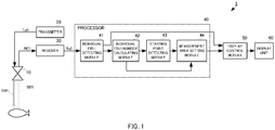
- Fig. 1 is a block diagram showing a configuration of a fish school finding device according to the present embodiment.
- the fish school finding device 1 includes a transducer 10, a transmitter 20, a receiver 30, a processor 40, a display control module 50, and a display unit 60.
- the "fish school finding device" of the present invention may include at least the processor 40.
- the transmitter 20 generates an ultrasonic transmission signal having a predetermined frequency, and outputs the ultrasonic transmission signal to the transducer 10.
- the transmitter 20 generates, for example, an ultrasonic transmission signal of 60kHz as the frequency f1.
- the frequency is not limited to this, and it may be appropriately set according to the target fish species and the like.
- the transmitter 20 may be capable of generating ultrasonic transmission signals of a plurality of frequencies. For example, the transmitter 20 may generate ultrasonic transmission signals having different frequencies of 60kHz as the frequency f1 and 100kHz as the frequency f2.
- the transmitter 20 outputs the ultrasonic transmission signals Txf1 of the frequencies f1 to the transducer 10 at predetermined intervals.
- the transducer 10 includes an ultrasonic transducer element having a structure corresponding to each frequency of the ultrasonic transmission signal described above.
- the transducer 10 transmits ultrasonic wave SWf1 into the sea water based on the ultrasonic transmission signals Txf1 of the respective frequencies generated by the transmitter 20.
- the transducer 10 receives a reflected wave SEf1 generated by reflection of an ultrasonic wave SWf1 on a target such as a fish school or a sea surface by an ultrasonic transducer element, generates an echo signal REf1 for each frequency, and outputs the echo signal to the receiver 30.
- the receiver 30 samples the echo signal REf1 for each PING inputted from the transceiver 10 at predetermined sampling timings, and generates a received data Rxf1.
- the sampling timing interval is set based on the distance resolution in the depth direction.
- the receiver 30 outputs the received data Rxf1 for each PING to the processor 40.
- the received data Rxf1 corresponds to "echo information obtained from ultrasonic waves transmitted in a depth direction at predetermined time intervals".
- "echo information obtained from ultrasonic waves transmitted in the depth direction at predetermined time intervals" is also referred to as "original echo”.
- the processor 40 includes an individual fish detecting module 41, an individual fish number calculating module 42, a starting point detecting module 43, and a measurement area setting module 44.
- the processor 40 detects an individual fish from the Rxf1, and automatically sets a measurement area based on the number of the individual fish.
- the processor 40 outputs the measurement area to the display control module 50.
- the starting point detecting module 43 corresponds to the "reference section detecting module" of the present invention.
- the display control module 50 combines the image data indicating the measurement area set by the measurement area setting module 44 with the above-described received data Rxf1.
- the display control module 50 outputs the synthesized image data to the display unit 60.
- the display unit 60 is, for example, a liquid crystal display, and displays image data from the display control module 50 on a screen.
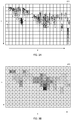
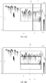
- Figs. 2A and 2B are explanatory diagrams for detecting an individual fish from an original echo.
- Figs. 3A and 3B are explanatory diagrams for calculating the number of individual fish for each of a plurality of sections from the detected individual fish.
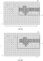
- Figs. 4A and 4B are explanatory diagrams for setting the measurement area from the detected individual fish.
- Figs. 5A and 5B are explanatory diagrams for setting the measurement area from the detected individual fish.
- Figs. 6A and 6B are explanatory diagrams for setting the measurement area from the detected individual fish.
- the X direction shown in Figs. 2A and 2B are the time axis direction and shows new data in the direction shown by the arrow (right hand in the drawing).
- the Y direction shown in Figs. 2A and 2B are a depth direction, and indicates data at a position deeper from the sea surface in the direction shown by the arrow (downward in the drawing).
- the individual fish detecting module 41 detects the individual fish by the echo signal REf1 received by the receiver 30.
- the individual fish detecting module 41 detects an individual fish with respect to the original data 410 composed of a two-dimensional data group in the X direction and the Y direction composed of a plurality of PING echo signal REf1.
- the individual fish detecting module 41 detects, for example, a width that is greater than or equal to the amplitude threshold for detecting an object in the echo signal REf1, and if the width is less than or equal to the threshold value for determining an individual fish, determines the portion in the original data 410 as the echo of the individual fish.
- the simple fish detecting module 41 extracts a point determined to be an echo of the individual fish as an individual fish extraction point.
- an individual fish extraction point is schematically indicated by *.
- a part of the detected individual fish is indicated by *, but other points are also indicated by the detected individual fish.
- the individual fish detecting module 41 outputs a composite image of the individual fish extraction points having two-dimensional distributions on the X-Y plane extracted by the individual fish detecting module 41 and the received data Rxf1 to the display control module 50.
- the display control module 50 may display the composite image on the display unit 60.
- the individual fish detecting module 41 generates the individual fish number detecting data 411 from the individual fish extracting point and the received data Rxf1.
- the individual fish number calculating module 42 divides the individual fish number detecting data 411 into a plurality of sections.
- the plurality of sections has a lattice shape divided by straight lines parallel to the X direction and the Y direction.
- the individual fish number calculating module 42 calculates the number of individual fish detected for each of the plurality of sections. For example, the individual fish number calculating module 42 divides the individual fish number detecting data 411 for each 100 pixels with respect to the X direction. For example, the individual fish number calculating module 42 divides the individual fish number detecting data 411 into a plurality of equal divisions of the whole area of the depth in the Y direction.
- the width of the section can be appropriately changed according to the use state.
- the individual fish number calculating module 42 generates individual fish number mapping data 420 as shown in Fig. 3B .
- the individual fish number mapping data 420 is data in which the number of individual fish detected in each section is set.
- the individual fish number calculating module 42 may output the individual fish number mapping data 420 to the display control module 50, and the display control module 50 may display the individual fish number mapping data 420 on the display unit 60.
- the individual fish number calculating module 42 may assign a color that makes the section itself darker as the number of detected individual fish per section increases. This makes it easier to grasp the two-dimensional distribution of the individual fish detected visually. For example, in the section displayed in the darkest color positioned slightly to the right from the central of Fig. 3B , the number of individual fish is 40, and the number of individual fish is the largest in the individual fish number mapping data 420.
- the starting point detecting module 43 detects a section having the largest individual fish number in the individual fish number mapping data 420 as a starting point.
- the starting point corresponds to the "reference section" of the present invention.
- the starting point is a section in which the number of individual fish is 40. It should be noted that the starting point is not limited to the section having the largest individual fish number in the individual fish number mapping data 420, and the section having the individual fish number equal to or larger than a predetermined threshold may be detected as the starting point.
- the measurement area setting module 44 determines the continuity of the depth direction (Y direction) and the time axis direction (X direction) based on the individual fish number mapping data 420, that is, the individual fish number of each of a plurality of sections.
- the determination of the continuity is performed based on the number of individual fishes in the adjacent sections in order from the starting point in the shallow direction (the -Y direction) along the Y direction or in the deep direction (the Y direction). For example, the measurement area setting module 44 compares the number of individual fish that is 30 in the section adjacent to the starting point in the -Y direction with the number of individual fish that is 40 in the starting point.
- the measurement area setting module 44 determines that adjacent sections have the continuity each other when the number of individual fish in adjacent sections is within a predetermined range each other (Condition 1), and the number of individual fish calculated for each sections are equal to or greater than a predetermined threshold number (Condition 2).
- the predetermined range is, for example, 50% or more and 200% or less of each other.
- the predetermined threshold number is, for example, 3 or more.
- the measurement area setting module 44 determines that the section of the starting point and the section adjacent to the starting point have the continuity.
- the measurement area setting module 44 determines the continuity of adjacent sections in order from the starting point along the Y direction in the shallow direction (-Y direction) or in the deep direction (Y direction). It should be noted that it is also possible to determine the continuity by only one of Condition 1 and Condition 2. However, determining the continuity in Conditions 1 and Condition 2 can improve the accuracy of the determination.
- the measurement area setting module 44 may terminate the determination in one direction along the Y direction in the section determined not to have continuity. As a result, unnecessary assessment of a section having no continuity is omitted, and the time required for determination is shortened.
- the measurement area setting module 44 may determine the continuity within a range of a predetermined number of sections from the starting point. For example, there is a case in which the fifth section is determined from the starting point by counting. Thereby, it is possible to quickly determine only the range determined in advance from the starting point.
- the measurement area setting module 44 determines the continuity of the section in the X direction (time axis direction). Similar to the determination of the continuity in the depth direction, the measurement area setting module 44 determines the continuity of the sections based on the number of individual fish in the sections adjacent to each other in the right direction (the newer of the time) or the left direction (the older of the time) along the X direction in order from the sections determined to have continuity.
- the measurement area setting module 44 sets the measurement area based on the continuity of the Y direction (depth direction) and the X direction (time axis direction) from the section of the starting point described above. As a result, the user automatically sets the measurement area without setting the measurement area by him/her.
- Fig. 5B , 6A, and 6B are examples of measurement areas, respectively.
- the measurement area setting module 44 sets sections determined to have continuity in the Y direction and the X direction (hereinafter, referred to as an area A) as a measurement area. Thereby, since only the section satisfying the condition of the measurement area is set as the measurement area, a more accurate measurement value can be obtained. It is also possible to use the area A as a fish school for analysis.
- the measurement area setting module 44 sets the area B as the measurement area.
- the area B is a measurement area of a rectangle defined by the area A.
- the area B corresponds to the area of the first rectangle in the present invention. That is, the area B is a rectangle having one side in the Y direction from the deepest section to the shallowest section in the Y direction in the area A, and one side in the X direction from the newest section to the oldest section in the X direction in the area A.
- the measurement area is set as a rectangle, it is possible to omit the labor of finely processing the measurement in the Y direction and the X direction.
- the measurement area setting module 44 sets the area C as the measurement area.
- the area C is a rectangle surrounding the area B.
- the area C corresponds to the area of the second rectangle in the present invention.
- area C may be an area expanded one section each of the Y direction and the X direction from the area B.
- the right end of the area B and the right end of the area C may be the same.
- the measurement area is set as a rectangle, it is possible to omit the labor of finely processing the measurement in the Y direction and the X direction.
- the measurement area can be set with a margin, the number of samples effective for measurement can be more effectively acquired for post-processing using the measurement area such as fish length measurement.
- processing is executed by a plurality of functional parts of the processor 40 in order to automatically set the measurement area, but this processing may be programmed and stored, and the program of the processing may be read and executed by an calculation device such as a computer.
- Fig. 7 is a flowchart showing processing for setting a measurement area.
- the calculation device performs a process of setting the measurement areas according to the flow schematically shown in the S101-S104 of Fig. 7 .
- the calculation device detects an individual fish from the received data (original echo) (S101 in Fig. 7 ).
- the calculation device calculates the number of individual fish for each section of the individual fish number detecting data composed of the X-Y two-dimensional distributions of the detected individual fish ( Fig. 7 :S102).
- the calculation device detects a starting point based on the calculated number of individual fish per section (S103 in Fig. 7 ).
- the calculation device sets a measurement area based on the detected starting point (S104 in Fig. 7 ).
- the calculation device displays the measurement area superimposed on the received data (original echo) (S105 in Fig. 7 ).
- the fish school finding device 1 can automatically provide the measurement area of the fish school from the received data (original echo), to an operator such as a fisherman.
- Fig. 8 is a block diagram showing a configuration of a fish school finding device according to the second embodiment.
- the fish school finding device 2 includes a shape accepting module 47 and an operation input unit 70 in addition to the configuration of the fish school finding device 1.
- the fish school finding device 2 includes a fish school distribution center depth detecting module 45 instead of the starting point detecting module 43 of the fish school finding device 1.
- the fish school distribution center depth detecting module 45 corresponds to the "reference section detecting module" of the present invention.
- the operation input unit 70 is used by the user to input, to the processor 40, an external shape that forms a measurement area.
- the operation input unit 70 may be, for example, a mouse, a keyboard, or the like connected to the processor 40.
- the shape accepting module 47 accepts the setting of the outer shape of the measurement area input from the operation input unit 70.
- the shape accepting module 47 inputs data of the outer shape to the measurement area setting module 46.
- the data of the external shape is a dimension (PING number) in the X direction and a dimension (depth range) in the Y direction.
- the measurement area setting module 46 sets an actual measurement area in accordance with the input data of the outer shape.
- the shape accepting module 47 may extract and set the outer shape from the manual measurement area input by the user.
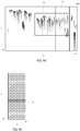
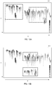
- Figs. 9A and 9B are explanatory diagrams for setting the fish school distribution center depth from the original echo.
- Figs. 10A and 10B are explanatory diagrams for setting the measurement area from the fish school distribution center depth.
- the display control module 50 outputs the received data Rxf1, which is the original echo, to the display unit 60.
- the display control module 50 outputs the outer shape D, which forms the measurement area input to the measurement area setting module 46 via the shape accepting module 47, to the display unit 60.
- the outer shape D is a rectangle, but can be appropriately changed according to the use situation.
- the individual fish detecting module 41 analyzes a predetermined area in the X-axis direction among the outer shape D in the original data 410 consist of the REf1. That is, the individual fish detecting module 41 extracts the detected individual fish in the predetermined area E shown in Fig. 9A same as the fish school finding device 1.
- the predetermined area E is in contact with the right end in the X-axis direction of the outer shape D, that is, the end having the newer time.
- a new data group can be used out of the outer shape D which is the area set by the user, and the deviation between the ship and the fish school due to the movement of the ship or the elapse of time can be reduced.
- the individual fish number calculating module 42 calculates the detected individual fish in the predetermined area E for each section.
- the fish school distribution center depth detecting module 45 totals the sum of the number of individual fish calculated by the individual fish number calculating module 42 for each row of the section arranged in the X-axis direction. That is, the fish school distribution center depth detecting module 45 totals the sum total of the number of individual fish in a plurality of PING sections for each row in the depth directions.
- the fish school distribution center depth detecting module 45 detects the row of the section witch has the largest number of individual fish as the fish school distribution center depth. For example, the row of the section to which the dark color is added shown in Fig. 9B is detected as the fish school distribution center depth F. In the second embodiment, the fish school distribution center depth F corresponds to the "reference section" of the present invention.
- the display control module 50 may output the fish school distribution center depth F in the predetermined area E to the display unit 60.
- the user can grasp the depth at which the largest number of individual fish is detected out of the fish school in the predetermined area E.
- the measurement area setting module 46 moves the outer shape D to the measurement area G.
- the measurement area setting module 46 sets the center in the depth direction of the outer shape D coincide with the center in the depth direction detected by the fish school distribution center depth detecting module 45. That is, the measurement area setting module 46 sets the measurement area G so that the center in the depth direction in the outer shape D coincides with the fish school distribution center depth F.
- the actual measurement area can be automatically set so that the point where the largest number of individual fish is detected becomes the central of the measurement area.
- each process may be programmed and stored, and the program of the process may be read out and executed by a calculation device such as a computer.
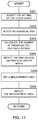
- Fig. 11 is a flowchart showing an outline process of setting the measurement area.
- the calculation device performs a process of setting the measurement areas according to the flow schematically shown in the S201-S205 of Fig. 2 .
- the calculation device accepts the setting of the outer shape ( Fig. 11 :S201).
- the calculation device detects an individual fish from the received data (original echo) (S202 in Fig. 11 ).
- the calculation device calculates the number of individual fish for each section out of the individual fish number detecting data composed of the X-Y two-dimensional distributions of the detected individual fish ( Fig. 11 :S203).
- the calculation device detects the fish school distribution center depth based on the calculated individual fish number for each section ( Fig. 11 :S204).
- the calculation device sets the measurement area based on the detected fish school distribution center depth ( Fig. 11 :S205).
- the calculation device displays the measurement area on the display screen in a state in which the measurement area is superimposed on the received data (original echo) ( Fig. 11 :S206).
- Fig. 12 is a block diagram showing a configuration of the fish length measuring device 3 according to the third embodiment.
- the fish length measuring device 3 of the present embodiment includes a fish length measuring module 80 in addition to the configuration of the fish school finding device 1.
- the fish length measuring module 80 measures the fish length of the individual fish included in the fish school by a known method.
- the fish length of the individual fish included in the measurement area set by the measurement area setting module 44 is measured.
- the display control module 50 may display the obtained fish length measurement data on the screen by superimposing the fish length measurement data on the received data (original echo).
- the measurement area setting module 44 or the measurement area setting module 46 sets only one measurement area on the original data in the above description, the measurement area setting module 44 or the measurement area setting module 46 may set a plurality of measurement areas.
- Figs. 13A and 13B are explanatory diagrams of a modified example.
- two measurement areas may be set in the X-axis direction (time axis direction).
- the fish school can be detected without leaking.
- two measurement areas may be set in the Y-axis direction (depth direction). As a result, even when there is a plurality of fish school having different depths, the fish school can be detected without leaking.
Landscapes
- Engineering & Computer Science (AREA)
- Physics & Mathematics (AREA)
- Radar, Positioning & Navigation (AREA)
- Remote Sensing (AREA)
- General Physics & Mathematics (AREA)
- Computer Networks & Wireless Communication (AREA)
- Acoustics & Sound (AREA)
- Computer Vision & Pattern Recognition (AREA)
- Theoretical Computer Science (AREA)
- Measurement Of Velocity Or Position Using Acoustic Or Ultrasonic Waves (AREA)
Abstract
Description
- The present invention relates to a fish school finding device, a fish length measuring device, a fish school finding method, and a fish school finding program, for transmitting an ultrasonic wave into water and detect an object like fish school from the echo signal.
- Conventionally, there has been disclosed a fish school finding device for transmitting ultrasonic waves into water and detecting fish school from an echo signal of the ultrasonic waves. As one type of such a fish school finding device, for example, as shown in
Patent Document 1, there is a fish school finding device that extracts fish school with high accuracy by binarizing data generated based on an echo signal with reference to a signal level. - Now, in order to protect fishery resources worldwide, annual fish catches are agreed for each fish species, each country, and each ship. For example, in TAC (Total Allowable Catch), annual fish catches for each country are determined for each fish species. On the other hand, in the IVQ (Individual Vessel Quota), the annual catch is determined for each fish species and for each fishing vessel. In the case where the catch exceeds the determined catch amount, various penalties are imposed, such as a reduction in the catch amount in the next year.
- Therefore, it is desirable that each fishing vessel can surely catch only fish of a target fish species or fish length.
- [Patent Document 1]
JP2014-077701A - However, in the fish school finding device disclosed in
Patent Document 1, it is necessary to set the measurement area of the fish species or the measurement area of the fish length by the user manually operating the operation unit while viewing the echo image. Therefore, it is not easy to set the measurement area to an appropriate area. In addition, the positional relationship between the ship and the fish school may change over time during operation. Therefore, as time elapses, the user needs to reset the measurement area while checking the echo image at any time. - An object of the present invention is to automatically set the measurement area of the fish species or the measurement area of the fish length, or the like.
- The present invention comprises: an individual fish detecting module configured to detect an individual fish from echo information obtained from ultrasonic waves transmitted in a depth direction at predetermined time intervals; an individual fish number calculating module configured to calculate a number of the individual fish for each of a plurality of two-dimensionally arrayed sections consisting of the depth direction and a time axis direction; a reference section detecting module configured to detect a reference section based on the number of the individual fish; and a measurement area setting module configured to set a measurement area based on the reference section.
- In this configuration, the number of individual fish detected from the original echo is calculated as the number of individual fish for each of a plurality of two-dimensionally arrayed sections. The measurement area is automatically set based on the number of individual fish calculated for each section.
- According to the present invention, the measurement area of the fish species, the measurement area of the fish length or the like can be automatically set.
-
-
Fig. 1 is a block diagram showing a configuration of a fish school finding device according to a first embodiment. -
Figs. 2A and 2B are explanatory diagrams for detecting an individual fish from an original echo. -
Figs. 3A and 3B are explanatory diagrams for calculating the number of individual fish for each of a plurality of sections from the detected individual fish. -
Figs. 4A and 4B are explanatory diagrams for setting a measurement area from the detected individual fish. -
Figs. 5A and 5B are explanatory diagrams for setting a measurement area from the detected individual fish. -
Figs. 6A and 6B are explanatory diagrams for setting a measurement area from the detected individual fish. -
Fig. 7 is a flowchart showing schematic processing of a processor, a display control module, and a display unit. -
Fig. 8 is a block diagram showing a configuration of a fish school finding device according to a second embodiment. -
Figs. 9A and 9B are explanatory diagrams for setting a fish school distribution center depth from the original echo. -
Figs. 10A and 10B are explanatory diagrams for setting a measurement area from a fish school distribution center depth. -
Fig. 11 is a flowchart showing schematic processing of a processor, a display control module, and a display unit. -
Fig. 12 is a block diagram showing a configuration of a fish length measuring device according to a third embodiment. -
Figs. 13A and 13B are explanatory diagrams of a modified example. - The configuration of the fish school finding device according to the first embodiment of the present invention will be described with reference to the drawings. Although the fish school finding device is described below as an example, the technical feature of the present application described below can be applied to other ultrasonic detecting device that transmit an ultrasonic signal and perform target object detection based on an echo signal of the ultrasonic signal. In addition, although an example in which the fish length measurement is described below, the present invention can be applied to a case in which information such as fish species discrimination.
-
Fig. 1 is a block diagram showing a configuration of a fish school finding device according to the present embodiment. - The fish
school finding device 1 includes atransducer 10, atransmitter 20, areceiver 30, aprocessor 40, adisplay control module 50, and adisplay unit 60. The "fish school finding device" of the present invention may include at least theprocessor 40. - The
transmitter 20 generates an ultrasonic transmission signal having a predetermined frequency, and outputs the ultrasonic transmission signal to thetransducer 10. Thetransmitter 20 generates, for example, an ultrasonic transmission signal of 60kHz as the frequency f1. The frequency is not limited to this, and it may be appropriately set according to the target fish species and the like. Thetransmitter 20 may be capable of generating ultrasonic transmission signals of a plurality of frequencies. For example, thetransmitter 20 may generate ultrasonic transmission signals having different frequencies of 60kHz as the frequency f1 and 100kHz as the frequency f2. - The
transmitter 20 outputs the ultrasonic transmission signals Txf1 of the frequencies f1 to thetransducer 10 at predetermined intervals. - The
transducer 10 includes an ultrasonic transducer element having a structure corresponding to each frequency of the ultrasonic transmission signal described above. Thetransducer 10 transmits ultrasonic wave SWf1 into the sea water based on the ultrasonic transmission signals Txf1 of the respective frequencies generated by thetransmitter 20. Thetransducer 10 receives a reflected wave SEf1 generated by reflection of an ultrasonic wave SWf1 on a target such as a fish school or a sea surface by an ultrasonic transducer element, generates an echo signal REf1 for each frequency, and outputs the echo signal to thereceiver 30. - The
receiver 30 samples the echo signal REf1 for each PING inputted from thetransceiver 10 at predetermined sampling timings, and generates a received data Rxf1. The sampling timing interval is set based on the distance resolution in the depth direction. Thereceiver 30 outputs the received data Rxf1 for each PING to theprocessor 40. The received data Rxf1 corresponds to "echo information obtained from ultrasonic waves transmitted in a depth direction at predetermined time intervals". Hereinafter, "echo information obtained from ultrasonic waves transmitted in the depth direction at predetermined time intervals" is also referred to as "original echo". - The
processor 40 includes an individualfish detecting module 41, an individual fishnumber calculating module 42, a startingpoint detecting module 43, and a measurementarea setting module 44. In general, theprocessor 40 detects an individual fish from the Rxf1, and automatically sets a measurement area based on the number of the individual fish. Theprocessor 40 outputs the measurement area to thedisplay control module 50. In the first embodiment, the startingpoint detecting module 43 corresponds to the "reference section detecting module" of the present invention. - The
display control module 50 combines the image data indicating the measurement area set by the measurementarea setting module 44 with the above-described received data Rxf1. Thedisplay control module 50 outputs the synthesized image data to thedisplay unit 60. Thedisplay unit 60 is, for example, a liquid crystal display, and displays image data from thedisplay control module 50 on a screen. - Next, a specific process performed by the
processor 40 will be described with reference toFigs. 2 to 6 . -
Figs. 2A and 2B are explanatory diagrams for detecting an individual fish from an original echo.Figs. 3A and 3B are explanatory diagrams for calculating the number of individual fish for each of a plurality of sections from the detected individual fish.Figs. 4A and 4B are explanatory diagrams for setting the measurement area from the detected individual fish.Figs. 5A and 5B are explanatory diagrams for setting the measurement area from the detected individual fish.Figs. 6A and 6B are explanatory diagrams for setting the measurement area from the detected individual fish. - The X direction shown in
Figs. 2A and 2B are the time axis direction and shows new data in the direction shown by the arrow (right hand in the drawing). In addition, the Y direction shown inFigs. 2A and 2B are a depth direction, and indicates data at a position deeper from the sea surface in the direction shown by the arrow (downward in the drawing). - The individual
fish detecting module 41 detects the individual fish by the echo signal REf1 received by thereceiver 30. The individualfish detecting module 41 detects an individual fish with respect to theoriginal data 410 composed of a two-dimensional data group in the X direction and the Y direction composed of a plurality of PING echo signal REf1. - The individual
fish detecting module 41 detects, for example, a width that is greater than or equal to the amplitude threshold for detecting an object in the echo signal REf1, and if the width is less than or equal to the threshold value for determining an individual fish, determines the portion in theoriginal data 410 as the echo of the individual fish. The simplefish detecting module 41 extracts a point determined to be an echo of the individual fish as an individual fish extraction point. InFig. 2B , an individual fish extraction point is schematically indicated by *. InFig. 2B , a part of the detected individual fish is indicated by *, but other points are also indicated by the detected individual fish. - The individual
fish detecting module 41 outputs a composite image of the individual fish extraction points having two-dimensional distributions on the X-Y plane extracted by the individualfish detecting module 41 and the received data Rxf1 to thedisplay control module 50. Thedisplay control module 50 may display the composite image on thedisplay unit 60. The individualfish detecting module 41 generates the individual fishnumber detecting data 411 from the individual fish extracting point and the received data Rxf1. - As shown in
Fig. 3A , the individual fishnumber calculating module 42 divides the individual fishnumber detecting data 411 into a plurality of sections. The plurality of sections has a lattice shape divided by straight lines parallel to the X direction and the Y direction. The individual fishnumber calculating module 42 calculates the number of individual fish detected for each of the plurality of sections. For example, the individual fishnumber calculating module 42 divides the individual fishnumber detecting data 411 for each 100 pixels with respect to the X direction. For example, the individual fishnumber calculating module 42 divides the individual fishnumber detecting data 411 into a plurality of equal divisions of the whole area of the depth in the Y direction. The width of the section can be appropriately changed according to the use state. - As a result, the individual fish
number calculating module 42 generates individual fishnumber mapping data 420 as shown inFig. 3B . The individual fishnumber mapping data 420 is data in which the number of individual fish detected in each section is set. - The individual fish
number calculating module 42 may output the individual fishnumber mapping data 420 to thedisplay control module 50, and thedisplay control module 50 may display the individual fishnumber mapping data 420 on thedisplay unit 60. At this time, as shown inFig. 3B , the individual fishnumber calculating module 42 may assign a color that makes the section itself darker as the number of detected individual fish per section increases. This makes it easier to grasp the two-dimensional distribution of the individual fish detected visually. For example, in the section displayed in the darkest color positioned slightly to the right from the central ofFig. 3B , the number of individual fish is 40, and the number of individual fish is the largest in the individual fishnumber mapping data 420. - The starting
point detecting module 43 detects a section having the largest individual fish number in the individual fishnumber mapping data 420 as a starting point. In the first embodiment, the starting point corresponds to the "reference section" of the present invention. In the example ofFigs. 3B and4A , the starting point is a section in which the number of individual fish is 40. It should be noted that the starting point is not limited to the section having the largest individual fish number in the individual fishnumber mapping data 420, and the section having the individual fish number equal to or larger than a predetermined threshold may be detected as the starting point. - The measurement
area setting module 44 determines the continuity of the depth direction (Y direction) and the time axis direction (X direction) based on the individual fishnumber mapping data 420, that is, the individual fish number of each of a plurality of sections. - As shown in
Fig. 4B , the determination of the continuity is performed based on the number of individual fishes in the adjacent sections in order from the starting point in the shallow direction (the -Y direction) along the Y direction or in the deep direction (the Y direction). For example, the measurementarea setting module 44 compares the number of individual fish that is 30 in the section adjacent to the starting point in the -Y direction with the number of individual fish that is 40 in the starting point. - The measurement
area setting module 44 determines that adjacent sections have the continuity each other when the number of individual fish in adjacent sections is within a predetermined range each other (Condition 1), and the number of individual fish calculated for each sections are equal to or greater than a predetermined threshold number (Condition 2). The predetermined range is, for example, 50% or more and 200% or less of each other. The predetermined threshold number is, for example, 3 or more. In this case, if the ratio between the number of individual fish in the section of the starting point and the number of individual fish in the section adjacent to the starting point are 50% or more and 200% or less each other, and the number of individual fish in the section of the starting point and the number of individual fish in the section adjacent to the starting point are 3 or more, the measurementarea setting module 44 determines that the section of the starting point and the section adjacent to the starting point have the continuity. - Using the same conditions, the measurement
area setting module 44 determines the continuity of adjacent sections in order from the starting point along the Y direction in the shallow direction (-Y direction) or in the deep direction (Y direction). It should be noted that it is also possible to determine the continuity by only one ofCondition 1 andCondition 2. However, determining the continuity inConditions 1 andCondition 2 can improve the accuracy of the determination. - The measurement
area setting module 44 may terminate the determination in one direction along the Y direction in the section determined not to have continuity. As a result, unnecessary assessment of a section having no continuity is omitted, and the time required for determination is shortened. In addition, the measurementarea setting module 44 may determine the continuity within a range of a predetermined number of sections from the starting point. For example, there is a case in which the fifth section is determined from the starting point by counting. Thereby, it is possible to quickly determine only the range determined in advance from the starting point. - By this processing, as shown in the hatched section in
Fig. 4B , an area having continuity in the Y direction can be detected. - Next, as shown in
Fig. 5A , the measurementarea setting module 44 determines the continuity of the section in the X direction (time axis direction). Similar to the determination of the continuity in the depth direction, the measurementarea setting module 44 determines the continuity of the sections based on the number of individual fish in the sections adjacent to each other in the right direction (the newer of the time) or the left direction (the older of the time) along the X direction in order from the sections determined to have continuity. - By this processing, as shown in the hatched section in
Fig. 5A , an area having continuity in the X direction can be detected. As a result, the continuity of the section along the Y direction and the X direction from the starting point can be determined. In the present embodiment, the continuity in the X direction is judged after the continuity in the Y direction is judged, but the continuity may be judged from any direction. - The measurement
area setting module 44 sets the measurement area based on the continuity of the Y direction (depth direction) and the X direction (time axis direction) from the section of the starting point described above. As a result, the user automatically sets the measurement area without setting the measurement area by him/her.Fig. 5B ,6A, and 6B are examples of measurement areas, respectively. - In the case of
Fig. 5B , the measurementarea setting module 44 sets sections determined to have continuity in the Y direction and the X direction (hereinafter, referred to as an area A) as a measurement area. Thereby, since only the section satisfying the condition of the measurement area is set as the measurement area, a more accurate measurement value can be obtained. It is also possible to use the area A as a fish school for analysis. - In the case of
Fig. 6A , the measurementarea setting module 44 sets the area B as the measurement area. The area B is a measurement area of a rectangle defined by the area A. The area B corresponds to the area of the first rectangle in the present invention. That is, the area B is a rectangle having one side in the Y direction from the deepest section to the shallowest section in the Y direction in the area A, and one side in the X direction from the newest section to the oldest section in the X direction in the area A. As a result, since the measurement area is set as a rectangle, it is possible to omit the labor of finely processing the measurement in the Y direction and the X direction. - In the case of
Fig. 6B , the measurementarea setting module 44 sets the area C as the measurement area. The area C is a rectangle surrounding the area B. The area C corresponds to the area of the second rectangle in the present invention. For example, area C may be an area expanded one section each of the Y direction and the X direction from the area B. - Since the new side (right side) of the area B in the X direction is the latest section, the right end of the area B and the right end of the area C may be the same. As a result, since the measurement area is set as a rectangle, it is possible to omit the labor of finely processing the measurement in the Y direction and the X direction. In addition, since the measurement area can be set with a margin, the number of samples effective for measurement can be more effectively acquired for post-processing using the measurement area such as fish length measurement.
- In the above description, an example has been described in which processing is executed by a plurality of functional parts of the
processor 40 in order to automatically set the measurement area, but this processing may be programmed and stored, and the program of the processing may be read and executed by an calculation device such as a computer. - In this case, the setting process may be performed according to the following flowchart.
Fig. 7 is a flowchart showing processing for setting a measurement area. - The calculation device performs a process of setting the measurement areas according to the flow schematically shown in the S101-S104 of
Fig. 7 . - The calculation device detects an individual fish from the received data (original echo) (S101 in
Fig. 7 ). - The calculation device calculates the number of individual fish for each section of the individual fish number detecting data composed of the X-Y two-dimensional distributions of the detected individual fish (
Fig. 7 :S102). - The calculation device detects a starting point based on the calculated number of individual fish per section (S103 in
Fig. 7 ). - The calculation device sets a measurement area based on the detected starting point (S104 in
Fig. 7 ). - The calculation device displays the measurement area superimposed on the received data (original echo) (S105 in
Fig. 7 ). - As a result, the fish
school finding device 1 can automatically provide the measurement area of the fish school from the received data (original echo), to an operator such as a fisherman. - Hereinafter, the configuration of the fish school finding device according to the second embodiment of the present invention will be described with reference to the drawings. In the description of the second embodiment of the present invention, the description of the same configuration as that of the first embodiment of the present invention is omitted, and only different points will be described.
-
Fig. 8 is a block diagram showing a configuration of a fish school finding device according to the second embodiment. - The fish
school finding device 2 includes ashape accepting module 47 and anoperation input unit 70 in addition to the configuration of the fishschool finding device 1. The fishschool finding device 2 includes a fish school distribution centerdepth detecting module 45 instead of the startingpoint detecting module 43 of the fishschool finding device 1. In the second embodiment, the fish school distribution centerdepth detecting module 45 corresponds to the "reference section detecting module" of the present invention. - The
operation input unit 70 is used by the user to input, to theprocessor 40, an external shape that forms a measurement area. Theoperation input unit 70 may be, for example, a mouse, a keyboard, or the like connected to theprocessor 40. - The
shape accepting module 47 accepts the setting of the outer shape of the measurement area input from theoperation input unit 70. Theshape accepting module 47 inputs data of the outer shape to the measurementarea setting module 46. The data of the external shape is a dimension (PING number) in the X direction and a dimension (depth range) in the Y direction. - The measurement
area setting module 46 sets an actual measurement area in accordance with the input data of the outer shape. Theshape accepting module 47 may extract and set the outer shape from the manual measurement area input by the user. - Next, a specific process performed by the
processor 40 in the fishschool finding device 2 will be described with reference toFigs. 9A and 9B , andFigs. 10A and 10B . -
Figs. 9A and 9B are explanatory diagrams for setting the fish school distribution center depth from the original echo.Figs. 10A and 10B are explanatory diagrams for setting the measurement area from the fish school distribution center depth. - As shown in
Fig. 9A , thedisplay control module 50 outputs the received data Rxf1, which is the original echo, to thedisplay unit 60. Thedisplay control module 50 outputs the outer shape D, which forms the measurement area input to the measurementarea setting module 46 via theshape accepting module 47, to thedisplay unit 60. In the present embodiment, the outer shape D is a rectangle, but can be appropriately changed according to the use situation. - The individual
fish detecting module 41 analyzes a predetermined area in the X-axis direction among the outer shape D in theoriginal data 410 consist of the REf1. That is, the individualfish detecting module 41 extracts the detected individual fish in the predetermined area E shown inFig. 9A same as the fishschool finding device 1. - It is preferable that the predetermined area E is in contact with the right end in the X-axis direction of the outer shape D, that is, the end having the newer time. As a result, a new data group can be used out of the outer shape D which is the area set by the user, and the deviation between the ship and the fish school due to the movement of the ship or the elapse of time can be reduced.
- As shown in
Fig. 9B , the individual fishnumber calculating module 42 calculates the detected individual fish in the predetermined area E for each section. The fish school distribution centerdepth detecting module 45 totals the sum of the number of individual fish calculated by the individual fishnumber calculating module 42 for each row of the section arranged in the X-axis direction. That is, the fish school distribution centerdepth detecting module 45 totals the sum total of the number of individual fish in a plurality of PING sections for each row in the depth directions. - The fish school distribution center
depth detecting module 45 detects the row of the section witch has the largest number of individual fish as the fish school distribution center depth. For example, the row of the section to which the dark color is added shown inFig. 9B is detected as the fish school distribution center depth F. In the second embodiment, the fish school distribution center depth F corresponds to the "reference section" of the present invention. - As shown in
Fig. 10A , thedisplay control module 50 may output the fish school distribution center depth F in the predetermined area E to thedisplay unit 60. Thus, the user can grasp the depth at which the largest number of individual fish is detected out of the fish school in the predetermined area E. - As shown in
Fig. 10B , the measurementarea setting module 46 moves the outer shape D to the measurement area G. At this time, the measurementarea setting module 46 sets the center in the depth direction of the outer shape D coincide with the center in the depth direction detected by the fish school distribution centerdepth detecting module 45. That is, the measurementarea setting module 46 sets the measurement area G so that the center in the depth direction in the outer shape D coincides with the fish school distribution center depth F. As a result, the actual measurement area can be automatically set so that the point where the largest number of individual fish is detected becomes the central of the measurement area. - Also in the fish
school finding device 2, in order to automatically set the measurement area in the same manner as in the fishschool finding device 1, each process may be programmed and stored, and the program of the process may be read out and executed by a calculation device such as a computer.Fig. 11 is a flowchart showing an outline process of setting the measurement area. - The calculation device performs a process of setting the measurement areas according to the flow schematically shown in the S201-S205 of
Fig. 2 . - The calculation device accepts the setting of the outer shape (
Fig. 11 :S201). - The calculation device detects an individual fish from the received data (original echo) (S202 in
Fig. 11 ). - The calculation device calculates the number of individual fish for each section out of the individual fish number detecting data composed of the X-Y two-dimensional distributions of the detected individual fish (
Fig. 11 :S203). - The calculation device detects the fish school distribution center depth based on the calculated individual fish number for each section (
Fig. 11 :S204). - The calculation device sets the measurement area based on the detected fish school distribution center depth (
Fig. 11 :S205). - The calculation device displays the measurement area on the display screen in a state in which the measurement area is superimposed on the received data (original echo) (
Fig. 11 :S206). - This makes it possible to automatically provide the operator such as a fisherman with the measurement area of the fish school from the received data (original echo).
- Hereinafter, a configuration of a fish length measuring device according to a third embodiment of the present invention will be described with reference to the drawings. In the description of the third embodiment of the present invention, the description of the same configuration as that of the first embodiment of the present invention is omitted, and only different points will be described.
-
Fig. 12 is a block diagram showing a configuration of the fishlength measuring device 3 according to the third embodiment. - The fish
length measuring device 3 of the present embodiment includes a fishlength measuring module 80 in addition to the configuration of the fishschool finding device 1. - The fish
length measuring module 80 measures the fish length of the individual fish included in the fish school by a known method. In the fishlength measuring device 3, the fish length of the individual fish included in the measurement area set by the measurementarea setting module 44 is measured. Although not shown, thedisplay control module 50 may display the obtained fish length measurement data on the screen by superimposing the fish length measurement data on the received data (original echo). - As a result, it is possible to automatically set the measurement area of the fish school from the received data (original echo) and to measure and provide the fish length of the individual fish included in the measurement area to an operator such as a fisherman.
- Although the measurement
area setting module 44 or the measurementarea setting module 46 sets only one measurement area on the original data in the above description, the measurementarea setting module 44 or the measurementarea setting module 46 may set a plurality of measurement areas.Figs. 13A and 13B are explanatory diagrams of a modified example. - For example, as shown in
Fig. 13A , two measurement areas may be set in the X-axis direction (time axis direction). As a result, even when there is a plurality of fish school different from each other in the moving direction of the ship, the fish school can be detected without leaking. - As shown in
Fig. 13B , two measurement areas may be set in the Y-axis direction (depth direction). As a result, even when there is a plurality of fish school having different depths, the fish school can be detected without leaking. -
- 1, 2, 3:
- Fish School Finding Device
- 10:
- Transducer
- 20:
- Transmitter
- 30:
- Receiver
- 40:
- Processor
- 41:
- Individual Fish Detecting Module
- 42:
- Individual Fish Number Calculating Module
- 43:
- Starting Point Detecting Module (Reference Section Detecting Module)
- 44:
- Measurement Area Setting Module
- 45:
- Fish School Distribution Center Depth Detecting Module (Reference Section Detecting Module)
- 46:
- Measurement Area Setting Module
- 47:
- Shape Accepting Module
Claims (14)
- A fish school finding device, comprising:an individual fish detecting module configured to detect an individual fish from echo information obtained from ultrasonic waves transmitted in a depth direction at predetermined time intervals;an individual fish number calculating module configured to calculate a number of the individual fish for each of a plurality of two-dimensionally arrayed sections consisting of the depth direction and a time axis direction;a reference section detecting module configured to detect a reference section based on the number of the individual fish; anda measurement area setting module configured to set a measurement area based on the reference section.
- The fish school finding device according to claim 1, wherein the reference section detecting module detects a section having a maximum number of individual fish as the reference section.
- The fish school finding device according to claim 1 or 2, wherein the measurement area setting module sets the measurement area based on a continuity of the plurality of two-dimensionally arrayed sections from the reference section.
- The fish school finding device according to any one of claims 1 to 3, wherein the measurement area setting module sets sections having a continuity in the depth direction and the time axis direction as the measurement area.
- The fish school finding device according to any one of claims 1 to 3, wherein the measurement area setting module sets a first rectangle defined by an area having a continuity in the depth direction and the time axis direction as the measurement area.
- The fish school finding device according to claim 5, wherein the measurement area setting module sets a second rectangle surrounding the first rectangle as the measurement area.
- The fish school finding device according to any of claims 1 to 6, wherein the measurement area setting module determines that adjacent sections have a continuity with each other in case that the number of individual fish calculated for each section is within a predetermined range of each other, and the number of individual fish calculated for each section is equal to or greater than a predetermined threshold number.
- The fish school finding device according to any one of claims 1 to 7, wherein the measurement area setting module determines a continuity from the reference section within a predetermined number of sections.
- The fish school finding device according to any one of claim 1 to 8, further comprising a shape accepting module configured to accept setting of an external shape of the measurement area,
wherein the measurement area setting module sets a center of the external shape in a depth direction to the reference section. - The fish school finding device according to claim 9, wherein the measurement area setting module sets the center of the external shape in the depth direction to the reference section at the latest position on the time axis direction of the external shape.
- The fish school finding device according to any one of claims 1 to 10, wherein the measurement area setting module sets a plurality of measurement areas.
- A fish length measuring device including a fish length measuring module configured to measure a fish length included in the measurement area, using the fish school finding device according to any one of claims 1 to 11.
- A fish school finding method, comprising:detecting an individual fish from echo information obtained from ultrasonic waves transmitted in a depth direction at predetermined time intervals;calculating a number of the individual fish for each of a plurality of two-dimensionally arrayed sections consisting of the depth direction and a time axis direction;detecting a reference section based on the number of the individual fish; andsetting a measurement area based on the reference section.
- A fish school finding program configured to cause a processor to execute processing comprising:detecting an individual fish from echo information obtained from ultrasonic waves transmitted in a depth direction at predetermined time intervals;calculating a number of the individual fish for each of a plurality of two-dimensionally arrayed sections consisting of the depth direction and a time axis direction;detecting a reference section based on the number of the individual fish; andsetting a measurement area based on the reference section.
Applications Claiming Priority (2)
| Application Number | Priority Date | Filing Date | Title |
|---|---|---|---|
| JP2017128305 | 2017-06-30 | ||
| PCT/JP2018/020514 WO2019003759A1 (en) | 2017-06-30 | 2018-05-29 | Fish school finding device, fish length measuring device, fish school finding method, and fish school finding program |
Publications (3)
| Publication Number | Publication Date |
|---|---|
| EP3647818A1 true EP3647818A1 (en) | 2020-05-06 |
| EP3647818A4 EP3647818A4 (en) | 2021-03-24 |
| EP3647818B1 EP3647818B1 (en) | 2024-03-20 |
Family
ID=64741374
Family Applications (1)
| Application Number | Title | Priority Date | Filing Date |
|---|---|---|---|
| EP18822651.8A Active EP3647818B1 (en) | 2017-06-30 | 2018-05-29 | Fish school finding device, fish length measuring device, fish school finding method, and fish school finding program |
Country Status (3)
| Country | Link |
|---|---|
| EP (1) | EP3647818B1 (en) |
| JP (1) | JP6773906B2 (en) |
| WO (1) | WO2019003759A1 (en) |
Cited By (1)
| Publication number | Priority date | Publication date | Assignee | Title |
|---|---|---|---|---|
| US20220000079A1 (en) * | 2020-07-06 | 2022-01-06 | Ecto, Inc. | Acoustics augmentation for monocular depth estimation |
Families Citing this family (5)
| Publication number | Priority date | Publication date | Assignee | Title |
|---|---|---|---|---|
| JP7419086B2 (en) * | 2020-01-29 | 2024-01-22 | 古野電気株式会社 | Underwater detection device and how to display underwater detection images |
| CN114185031A (en) * | 2020-09-15 | 2022-03-15 | Oppo广东移动通信有限公司 | Fish shoal positioning method and related device |
| JP2023166224A (en) * | 2022-05-09 | 2023-11-21 | 古野電気株式会社 | Fish finder, image generation method and program |
| CN115151132B (en) * | 2022-05-25 | 2023-08-18 | 广东逸动科技有限公司 | Fishing method, fishing device, fishing boat, fishing system, and readable storage medium |
| CN120405687B (en) * | 2024-05-31 | 2025-11-11 | 古野电气株式会社 | Monitoring device and monitoring method for aquatic organisms |
Family Cites Families (7)
| Publication number | Priority date | Publication date | Assignee | Title |
|---|---|---|---|---|
| JPH0719020Y2 (en) * | 1986-11-11 | 1995-05-01 | 株式会社カイジョー | Target tracking system scanning sonar |
| JP4475982B2 (en) * | 2004-03-01 | 2010-06-09 | 古野電気株式会社 | Weighing fish finder and fish length measuring method |
| JP5303284B2 (en) * | 2009-01-14 | 2013-10-02 | 日本無線株式会社 | Target image tracking device and target image tracking method |
| JP5700500B2 (en) * | 2010-07-23 | 2015-04-15 | 古野電気株式会社 | Underwater detection device, fish detection device, underwater detection method, and fish detection method |
| JP2014077701A (en) | 2012-10-10 | 2014-05-01 | Furuno Electric Co Ltd | Fish finding device, signal processing device, fish finder, fish finding method and program |
| JP6441735B2 (en) * | 2015-04-20 | 2018-12-19 | 古野電気株式会社 | Underwater detector |
| EP3153881A1 (en) * | 2015-10-06 | 2017-04-12 | Furuno Electric Company Limited | Detection apparatus, fish finder, and radar |
-
2018
- 2018-05-29 EP EP18822651.8A patent/EP3647818B1/en active Active
- 2018-05-29 JP JP2019526710A patent/JP6773906B2/en active Active
- 2018-05-29 WO PCT/JP2018/020514 patent/WO2019003759A1/en not_active Ceased
Cited By (1)
| Publication number | Priority date | Publication date | Assignee | Title |
|---|---|---|---|---|
| US20220000079A1 (en) * | 2020-07-06 | 2022-01-06 | Ecto, Inc. | Acoustics augmentation for monocular depth estimation |
Also Published As
| Publication number | Publication date |
|---|---|
| JP6773906B2 (en) | 2020-10-21 |
| JPWO2019003759A1 (en) | 2020-04-23 |
| EP3647818A4 (en) | 2021-03-24 |
| WO2019003759A1 (en) | 2019-01-03 |
| EP3647818B1 (en) | 2024-03-20 |
Similar Documents
| Publication | Publication Date | Title |
|---|---|---|
| EP3647818B1 (en) | Fish school finding device, fish length measuring device, fish school finding method, and fish school finding program | |
| US20130343151A1 (en) | Underwater detection device | |
| EP1913874A1 (en) | Ultrasound diagnostic apparatus and method for measuring a size of a target object | |
| EP2939598A1 (en) | Ultrasonic diagnostic device and elasticity evaluation method | |
| EP3290947B1 (en) | Signal processing device and radar device | |
| EP3153884A1 (en) | Detection apparatus, fish finder, and radar | |
| EP2410349B1 (en) | Method and apparatus for underwater detection and fish school detection | |
| EP3086137B1 (en) | Underwater detection apparatus | |
| JP6084810B2 (en) | Tracking processing apparatus and tracking processing method | |
| EP2527864A1 (en) | Sensor image display device and method | |
| GB2506995A (en) | Fish type distinguishing device, signal processing apparatus, and underwater detector | |
| US11020088B2 (en) | Program, method and device for ultrasonic diagnosis | |
| EP3269308A1 (en) | Ultrasonic diagnostic device | |
| JP2019107419A5 (en) | ||
| JP6589619B2 (en) | Ultrasonic diagnostic equipment | |
| JP6347660B2 (en) | Fish finder, single fish detection method, and single fish detection program | |
| EP3510937B1 (en) | Ultrasonic diagnosis device and operation method therefor | |
| EP3153883B1 (en) | Detection apparatus, underwater detection apparatus, radar apparatus, and detection method | |
| JP6674479B2 (en) | Underwater detection device and display method | |
| JP2014077701A (en) | Fish finding device, signal processing device, fish finder, fish finding method and program | |
| CN110604596B (en) | Ultrasonic imaging method of hip joint and hip joint imaging system | |
| KR101286060B1 (en) | Adaptive signal processing method and apparatus thereof | |
| US9585638B2 (en) | System for classifying palpable soft tissue masses using A-mode echographs | |
| US11259779B2 (en) | Ultrasound body tissue detecting device, ultrasound body tissue detecting method, and ultrasound body tissue detecting program | |
| US9585630B2 (en) | Ultrasonic measurement apparatus and ultrasonic measurement method |
Legal Events
| Date | Code | Title | Description |
|---|---|---|---|
| STAA | Information on the status of an ep patent application or granted ep patent |
Free format text: STATUS: THE INTERNATIONAL PUBLICATION HAS BEEN MADE |
|
| PUAI | Public reference made under article 153(3) epc to a published international application that has entered the european phase |
Free format text: ORIGINAL CODE: 0009012 |
|
| STAA | Information on the status of an ep patent application or granted ep patent |
Free format text: STATUS: REQUEST FOR EXAMINATION WAS MADE |
|
| 17P | Request for examination filed |
Effective date: 20200127 |
|
| AK | Designated contracting states |
Kind code of ref document: A1 Designated state(s): AL AT BE BG CH CY CZ DE DK EE ES FI FR GB GR HR HU IE IS IT LI LT LU LV MC MK MT NL NO PL PT RO RS SE SI SK SM TR |
|
| AX | Request for extension of the european patent |
Extension state: BA ME |
|
| DAV | Request for validation of the european patent (deleted) | ||
| DAX | Request for extension of the european patent (deleted) | ||
| A4 | Supplementary search report drawn up and despatched |
Effective date: 20210224 |
|
| RIC1 | Information provided on ipc code assigned before grant |
Ipc: G06T 7/11 20170101ALI20210218BHEP Ipc: G01S 15/89 20060101ALI20210218BHEP Ipc: G01S 7/62 20060101ALI20210218BHEP Ipc: G01S 15/96 20060101AFI20210218BHEP Ipc: G01S 7/539 20060101ALI20210218BHEP Ipc: G06T 7/187 20170101ALI20210218BHEP |
|
| GRAP | Despatch of communication of intention to grant a patent |
Free format text: ORIGINAL CODE: EPIDOSNIGR1 |
|
| STAA | Information on the status of an ep patent application or granted ep patent |
Free format text: STATUS: GRANT OF PATENT IS INTENDED |
|
| INTG | Intention to grant announced |
Effective date: 20231130 |
|
| GRAS | Grant fee paid |
Free format text: ORIGINAL CODE: EPIDOSNIGR3 |
|
| GRAA | (expected) grant |
Free format text: ORIGINAL CODE: 0009210 |
|
| STAA | Information on the status of an ep patent application or granted ep patent |
Free format text: STATUS: THE PATENT HAS BEEN GRANTED |
|
| AK | Designated contracting states |
Kind code of ref document: B1 Designated state(s): AL AT BE BG CH CY CZ DE DK EE ES FI FR GB GR HR HU IE IS IT LI LT LU LV MC MK MT NL NO PL PT RO RS SE SI SK SM TR |
|
| REG | Reference to a national code |
Ref country code: GB Ref legal event code: FG4D |
|
| REG | Reference to a national code |
Ref country code: CH Ref legal event code: EP |
|
| REG | Reference to a national code |
Ref country code: IE Ref legal event code: FG4D |
|
| REG | Reference to a national code |
Ref country code: DE Ref legal event code: R096 Ref document number: 602018066941 Country of ref document: DE |
|
| PG25 | Lapsed in a contracting state [announced via postgrant information from national office to epo] |
Ref country code: LT Free format text: LAPSE BECAUSE OF FAILURE TO SUBMIT A TRANSLATION OF THE DESCRIPTION OR TO PAY THE FEE WITHIN THE PRESCRIBED TIME-LIMIT Effective date: 20240320 |
|
| REG | Reference to a national code |
Ref country code: LT Ref legal event code: MG9D |
|
| PG25 | Lapsed in a contracting state [announced via postgrant information from national office to epo] |
Ref country code: GR Free format text: LAPSE BECAUSE OF FAILURE TO SUBMIT A TRANSLATION OF THE DESCRIPTION OR TO PAY THE FEE WITHIN THE PRESCRIBED TIME-LIMIT Effective date: 20240621 |
|
| PG25 | Lapsed in a contracting state [announced via postgrant information from national office to epo] |
Ref country code: RS Free format text: LAPSE BECAUSE OF FAILURE TO SUBMIT A TRANSLATION OF THE DESCRIPTION OR TO PAY THE FEE WITHIN THE PRESCRIBED TIME-LIMIT Effective date: 20240620 Ref country code: HR Free format text: LAPSE BECAUSE OF FAILURE TO SUBMIT A TRANSLATION OF THE DESCRIPTION OR TO PAY THE FEE WITHIN THE PRESCRIBED TIME-LIMIT Effective date: 20240320 |
|
| REG | Reference to a national code |
Ref country code: NL Ref legal event code: MP Effective date: 20240320 |
|
| PG25 | Lapsed in a contracting state [announced via postgrant information from national office to epo] |
Ref country code: RS Free format text: LAPSE BECAUSE OF FAILURE TO SUBMIT A TRANSLATION OF THE DESCRIPTION OR TO PAY THE FEE WITHIN THE PRESCRIBED TIME-LIMIT Effective date: 20240620 Ref country code: NO Free format text: LAPSE BECAUSE OF FAILURE TO SUBMIT A TRANSLATION OF THE DESCRIPTION OR TO PAY THE FEE WITHIN THE PRESCRIBED TIME-LIMIT Effective date: 20240620 Ref country code: LT Free format text: LAPSE BECAUSE OF FAILURE TO SUBMIT A TRANSLATION OF THE DESCRIPTION OR TO PAY THE FEE WITHIN THE PRESCRIBED TIME-LIMIT Effective date: 20240320 Ref country code: HR Free format text: LAPSE BECAUSE OF FAILURE TO SUBMIT A TRANSLATION OF THE DESCRIPTION OR TO PAY THE FEE WITHIN THE PRESCRIBED TIME-LIMIT Effective date: 20240320 Ref country code: GR Free format text: LAPSE BECAUSE OF FAILURE TO SUBMIT A TRANSLATION OF THE DESCRIPTION OR TO PAY THE FEE WITHIN THE PRESCRIBED TIME-LIMIT Effective date: 20240621 Ref country code: FI Free format text: LAPSE BECAUSE OF FAILURE TO SUBMIT A TRANSLATION OF THE DESCRIPTION OR TO PAY THE FEE WITHIN THE PRESCRIBED TIME-LIMIT Effective date: 20240320 Ref country code: BG Free format text: LAPSE BECAUSE OF FAILURE TO SUBMIT A TRANSLATION OF THE DESCRIPTION OR TO PAY THE FEE WITHIN THE PRESCRIBED TIME-LIMIT Effective date: 20240320 |
|
| REG | Reference to a national code |
Ref country code: AT Ref legal event code: MK05 Ref document number: 1668313 Country of ref document: AT Kind code of ref document: T Effective date: 20240320 |
|
| PG25 | Lapsed in a contracting state [announced via postgrant information from national office to epo] |
Ref country code: SE Free format text: LAPSE BECAUSE OF FAILURE TO SUBMIT A TRANSLATION OF THE DESCRIPTION OR TO PAY THE FEE WITHIN THE PRESCRIBED TIME-LIMIT Effective date: 20240320 Ref country code: LV Free format text: LAPSE BECAUSE OF FAILURE TO SUBMIT A TRANSLATION OF THE DESCRIPTION OR TO PAY THE FEE WITHIN THE PRESCRIBED TIME-LIMIT Effective date: 20240320 |
|
| PG25 | Lapsed in a contracting state [announced via postgrant information from national office to epo] |
Ref country code: NL Free format text: LAPSE BECAUSE OF FAILURE TO SUBMIT A TRANSLATION OF THE DESCRIPTION OR TO PAY THE FEE WITHIN THE PRESCRIBED TIME-LIMIT Effective date: 20240320 |
|
| PG25 | Lapsed in a contracting state [announced via postgrant information from national office to epo] |
Ref country code: NL Free format text: LAPSE BECAUSE OF FAILURE TO SUBMIT A TRANSLATION OF THE DESCRIPTION OR TO PAY THE FEE WITHIN THE PRESCRIBED TIME-LIMIT Effective date: 20240320 |
|
| PG25 | Lapsed in a contracting state [announced via postgrant information from national office to epo] |
Ref country code: IS Free format text: LAPSE BECAUSE OF FAILURE TO SUBMIT A TRANSLATION OF THE DESCRIPTION OR TO PAY THE FEE WITHIN THE PRESCRIBED TIME-LIMIT Effective date: 20240720 |
|
| PG25 | Lapsed in a contracting state [announced via postgrant information from national office to epo] |
Ref country code: PT Free format text: LAPSE BECAUSE OF FAILURE TO SUBMIT A TRANSLATION OF THE DESCRIPTION OR TO PAY THE FEE WITHIN THE PRESCRIBED TIME-LIMIT Effective date: 20240722 Ref country code: SM Free format text: LAPSE BECAUSE OF FAILURE TO SUBMIT A TRANSLATION OF THE DESCRIPTION OR TO PAY THE FEE WITHIN THE PRESCRIBED TIME-LIMIT Effective date: 20240320 |
|
| PG25 | Lapsed in a contracting state [announced via postgrant information from national office to epo] |
Ref country code: ES Free format text: LAPSE BECAUSE OF FAILURE TO SUBMIT A TRANSLATION OF THE DESCRIPTION OR TO PAY THE FEE WITHIN THE PRESCRIBED TIME-LIMIT Effective date: 20240320 |
|
| PG25 | Lapsed in a contracting state [announced via postgrant information from national office to epo] |
Ref country code: CZ Free format text: LAPSE BECAUSE OF FAILURE TO SUBMIT A TRANSLATION OF THE DESCRIPTION OR TO PAY THE FEE WITHIN THE PRESCRIBED TIME-LIMIT Effective date: 20240320 Ref country code: EE Free format text: LAPSE BECAUSE OF FAILURE TO SUBMIT A TRANSLATION OF THE DESCRIPTION OR TO PAY THE FEE WITHIN THE PRESCRIBED TIME-LIMIT Effective date: 20240320 |
|
| PG25 | Lapsed in a contracting state [announced via postgrant information from national office to epo] |
Ref country code: AT Free format text: LAPSE BECAUSE OF FAILURE TO SUBMIT A TRANSLATION OF THE DESCRIPTION OR TO PAY THE FEE WITHIN THE PRESCRIBED TIME-LIMIT Effective date: 20240320 |
|
| PG25 | Lapsed in a contracting state [announced via postgrant information from national office to epo] |
Ref country code: PL Free format text: LAPSE BECAUSE OF FAILURE TO SUBMIT A TRANSLATION OF THE DESCRIPTION OR TO PAY THE FEE WITHIN THE PRESCRIBED TIME-LIMIT Effective date: 20240320 |
|
| PG25 | Lapsed in a contracting state [announced via postgrant information from national office to epo] |
Ref country code: SK Free format text: LAPSE BECAUSE OF FAILURE TO SUBMIT A TRANSLATION OF THE DESCRIPTION OR TO PAY THE FEE WITHIN THE PRESCRIBED TIME-LIMIT Effective date: 20240320 |
|
| PG25 | Lapsed in a contracting state [announced via postgrant information from national office to epo] |
Ref country code: SM Free format text: LAPSE BECAUSE OF FAILURE TO SUBMIT A TRANSLATION OF THE DESCRIPTION OR TO PAY THE FEE WITHIN THE PRESCRIBED TIME-LIMIT Effective date: 20240320 Ref country code: SK Free format text: LAPSE BECAUSE OF FAILURE TO SUBMIT A TRANSLATION OF THE DESCRIPTION OR TO PAY THE FEE WITHIN THE PRESCRIBED TIME-LIMIT Effective date: 20240320 Ref country code: RO Free format text: LAPSE BECAUSE OF FAILURE TO SUBMIT A TRANSLATION OF THE DESCRIPTION OR TO PAY THE FEE WITHIN THE PRESCRIBED TIME-LIMIT Effective date: 20240320 Ref country code: PT Free format text: LAPSE BECAUSE OF FAILURE TO SUBMIT A TRANSLATION OF THE DESCRIPTION OR TO PAY THE FEE WITHIN THE PRESCRIBED TIME-LIMIT Effective date: 20240722 Ref country code: PL Free format text: LAPSE BECAUSE OF FAILURE TO SUBMIT A TRANSLATION OF THE DESCRIPTION OR TO PAY THE FEE WITHIN THE PRESCRIBED TIME-LIMIT Effective date: 20240320 Ref country code: IS Free format text: LAPSE BECAUSE OF FAILURE TO SUBMIT A TRANSLATION OF THE DESCRIPTION OR TO PAY THE FEE WITHIN THE PRESCRIBED TIME-LIMIT Effective date: 20240720 Ref country code: ES Free format text: LAPSE BECAUSE OF FAILURE TO SUBMIT A TRANSLATION OF THE DESCRIPTION OR TO PAY THE FEE WITHIN THE PRESCRIBED TIME-LIMIT Effective date: 20240320 Ref country code: EE Free format text: LAPSE BECAUSE OF FAILURE TO SUBMIT A TRANSLATION OF THE DESCRIPTION OR TO PAY THE FEE WITHIN THE PRESCRIBED TIME-LIMIT Effective date: 20240320 Ref country code: CZ Free format text: LAPSE BECAUSE OF FAILURE TO SUBMIT A TRANSLATION OF THE DESCRIPTION OR TO PAY THE FEE WITHIN THE PRESCRIBED TIME-LIMIT Effective date: 20240320 Ref country code: AT Free format text: LAPSE BECAUSE OF FAILURE TO SUBMIT A TRANSLATION OF THE DESCRIPTION OR TO PAY THE FEE WITHIN THE PRESCRIBED TIME-LIMIT Effective date: 20240320 |
|
| REG | Reference to a national code |
Ref country code: DE Ref legal event code: R119 Ref document number: 602018066941 Country of ref document: DE |
|
| PG25 | Lapsed in a contracting state [announced via postgrant information from national office to epo] |
Ref country code: IT Free format text: LAPSE BECAUSE OF FAILURE TO SUBMIT A TRANSLATION OF THE DESCRIPTION OR TO PAY THE FEE WITHIN THE PRESCRIBED TIME-LIMIT Effective date: 20240320 |
|
| REG | Reference to a national code |
Ref country code: CH Ref legal event code: PL |
|
| PG25 | Lapsed in a contracting state [announced via postgrant information from national office to epo] |
Ref country code: IT Free format text: LAPSE BECAUSE OF FAILURE TO SUBMIT A TRANSLATION OF THE DESCRIPTION OR TO PAY THE FEE WITHIN THE PRESCRIBED TIME-LIMIT Effective date: 20240320 |
|
| PG25 | Lapsed in a contracting state [announced via postgrant information from national office to epo] |
Ref country code: MC Free format text: LAPSE BECAUSE OF FAILURE TO SUBMIT A TRANSLATION OF THE DESCRIPTION OR TO PAY THE FEE WITHIN THE PRESCRIBED TIME-LIMIT Effective date: 20240320 |
|
| PG25 | Lapsed in a contracting state [announced via postgrant information from national office to epo] |
Ref country code: DK Free format text: LAPSE BECAUSE OF FAILURE TO SUBMIT A TRANSLATION OF THE DESCRIPTION OR TO PAY THE FEE WITHIN THE PRESCRIBED TIME-LIMIT Effective date: 20240320 |
|
| PG25 | Lapsed in a contracting state [announced via postgrant information from national office to epo] |
Ref country code: LU Free format text: LAPSE BECAUSE OF NON-PAYMENT OF DUE FEES Effective date: 20240529 |
|
| PLBE | No opposition filed within time limit |
Free format text: ORIGINAL CODE: 0009261 |
|
| STAA | Information on the status of an ep patent application or granted ep patent |
Free format text: STATUS: NO OPPOSITION FILED WITHIN TIME LIMIT |
|
| PG25 | Lapsed in a contracting state [announced via postgrant information from national office to epo] |
Ref country code: MC Free format text: LAPSE BECAUSE OF FAILURE TO SUBMIT A TRANSLATION OF THE DESCRIPTION OR TO PAY THE FEE WITHIN THE PRESCRIBED TIME-LIMIT Effective date: 20240320 Ref country code: LU Free format text: LAPSE BECAUSE OF NON-PAYMENT OF DUE FEES Effective date: 20240529 Ref country code: DK Free format text: LAPSE BECAUSE OF FAILURE TO SUBMIT A TRANSLATION OF THE DESCRIPTION OR TO PAY THE FEE WITHIN THE PRESCRIBED TIME-LIMIT Effective date: 20240320 Ref country code: CH Free format text: LAPSE BECAUSE OF NON-PAYMENT OF DUE FEES Effective date: 20240531 |
|
| REG | Reference to a national code |
Ref country code: BE Ref legal event code: MM Effective date: 20240531 |
|
| 26N | No opposition filed |
Effective date: 20241223 |
|
| PG25 | Lapsed in a contracting state [announced via postgrant information from national office to epo] |
Ref country code: DE Free format text: LAPSE BECAUSE OF NON-PAYMENT OF DUE FEES Effective date: 20241203 |
|
| PG25 | Lapsed in a contracting state [announced via postgrant information from national office to epo] |
Ref country code: IE Free format text: LAPSE BECAUSE OF NON-PAYMENT OF DUE FEES Effective date: 20240529 |
|
| PG25 | Lapsed in a contracting state [announced via postgrant information from national office to epo] |
Ref country code: BE Free format text: LAPSE BECAUSE OF NON-PAYMENT OF DUE FEES Effective date: 20240531 Ref country code: SI Free format text: LAPSE BECAUSE OF FAILURE TO SUBMIT A TRANSLATION OF THE DESCRIPTION OR TO PAY THE FEE WITHIN THE PRESCRIBED TIME-LIMIT Effective date: 20240320 |
|
| PG25 | Lapsed in a contracting state [announced via postgrant information from national office to epo] |
Ref country code: FR Free format text: LAPSE BECAUSE OF NON-PAYMENT OF DUE FEES Effective date: 20240531 |
|
| PG25 | Lapsed in a contracting state [announced via postgrant information from national office to epo] |
Ref country code: CY Free format text: LAPSE BECAUSE OF FAILURE TO SUBMIT A TRANSLATION OF THE DESCRIPTION OR TO PAY THE FEE WITHIN THE PRESCRIBED TIME-LIMIT; INVALID AB INITIO Effective date: 20180529 |
|
| PG25 | Lapsed in a contracting state [announced via postgrant information from national office to epo] |
Ref country code: HU Free format text: LAPSE BECAUSE OF FAILURE TO SUBMIT A TRANSLATION OF THE DESCRIPTION OR TO PAY THE FEE WITHIN THE PRESCRIBED TIME-LIMIT; INVALID AB INITIO Effective date: 20180529 |
|
| PGFP | Annual fee paid to national office [announced via postgrant information from national office to epo] |
Ref country code: GB Payment date: 20260323 Year of fee payment: 9 |