EP3647817A1 - Track prediction device, track prediction method, and track prediction program - Google Patents
Track prediction device, track prediction method, and track prediction program Download PDFInfo
- Publication number
- EP3647817A1 EP3647817A1 EP18825136.7A EP18825136A EP3647817A1 EP 3647817 A1 EP3647817 A1 EP 3647817A1 EP 18825136 A EP18825136 A EP 18825136A EP 3647817 A1 EP3647817 A1 EP 3647817A1
- Authority
- EP
- European Patent Office
- Prior art keywords
- course
- angular velocity
- calculating
- calculating part
- estimated position
- Prior art date
- Legal status (The legal status is an assumption and is not a legal conclusion. Google has not performed a legal analysis and makes no representation as to the accuracy of the status listed.)
- Withdrawn
Links
- 238000000034 method Methods 0.000 title claims description 14
- 238000001514 detection method Methods 0.000 claims abstract description 12
- 230000010354 integration Effects 0.000 claims abstract description 10
- 238000012545 processing Methods 0.000 claims description 8
- 230000001133 acceleration Effects 0.000 description 11
- 238000004364 calculation method Methods 0.000 description 6
- 230000000052 comparative effect Effects 0.000 description 4
- 238000004088 simulation Methods 0.000 description 2
- 238000006243 chemical reaction Methods 0.000 description 1
- 230000000694 effects Effects 0.000 description 1
- 239000011159 matrix material Substances 0.000 description 1
- 238000005259 measurement Methods 0.000 description 1
Images




Classifications
-
- G—PHYSICS
- G01—MEASURING; TESTING
- G01C—MEASURING DISTANCES, LEVELS OR BEARINGS; SURVEYING; NAVIGATION; GYROSCOPIC INSTRUMENTS; PHOTOGRAMMETRY OR VIDEOGRAMMETRY
- G01C21/00—Navigation; Navigational instruments not provided for in groups G01C1/00 - G01C19/00
- G01C21/10—Navigation; Navigational instruments not provided for in groups G01C1/00 - G01C19/00 by using measurements of speed or acceleration
-
- G—PHYSICS
- G01—MEASURING; TESTING
- G01S—RADIO DIRECTION-FINDING; RADIO NAVIGATION; DETERMINING DISTANCE OR VELOCITY BY USE OF RADIO WAVES; LOCATING OR PRESENCE-DETECTING BY USE OF THE REFLECTION OR RERADIATION OF RADIO WAVES; ANALOGOUS ARRANGEMENTS USING OTHER WAVES
- G01S19/00—Satellite radio beacon positioning systems; Determining position, velocity or attitude using signals transmitted by such systems
- G01S19/38—Determining a navigation solution using signals transmitted by a satellite radio beacon positioning system
- G01S19/39—Determining a navigation solution using signals transmitted by a satellite radio beacon positioning system the satellite radio beacon positioning system transmitting time-stamped messages, e.g. GPS [Global Positioning System], GLONASS [Global Orbiting Navigation Satellite System] or GALILEO
- G01S19/42—Determining position
- G01S19/48—Determining position by combining or switching between position solutions derived from the satellite radio beacon positioning system and position solutions derived from a further system
- G01S19/49—Determining position by combining or switching between position solutions derived from the satellite radio beacon positioning system and position solutions derived from a further system whereby the further system is an inertial position system, e.g. loosely-coupled
-
- G—PHYSICS
- G01—MEASURING; TESTING
- G01C—MEASURING DISTANCES, LEVELS OR BEARINGS; SURVEYING; NAVIGATION; GYROSCOPIC INSTRUMENTS; PHOTOGRAMMETRY OR VIDEOGRAMMETRY
- G01C21/00—Navigation; Navigational instruments not provided for in groups G01C1/00 - G01C19/00
- G01C21/10—Navigation; Navigational instruments not provided for in groups G01C1/00 - G01C19/00 by using measurements of speed or acceleration
- G01C21/12—Navigation; Navigational instruments not provided for in groups G01C1/00 - G01C19/00 by using measurements of speed or acceleration executed aboard the object being navigated; Dead reckoning
- G01C21/16—Navigation; Navigational instruments not provided for in groups G01C1/00 - G01C19/00 by using measurements of speed or acceleration executed aboard the object being navigated; Dead reckoning by integrating acceleration or speed, i.e. inertial navigation
-
- G—PHYSICS
- G01—MEASURING; TESTING
- G01P—MEASURING LINEAR OR ANGULAR SPEED, ACCELERATION, DECELERATION, OR SHOCK; INDICATING PRESENCE, ABSENCE, OR DIRECTION, OF MOVEMENT
- G01P3/00—Measuring linear or angular speed; Measuring differences of linear or angular speeds
- G01P3/42—Devices characterised by the use of electric or magnetic means
- G01P3/44—Devices characterised by the use of electric or magnetic means for measuring angular speed
-
- G—PHYSICS
- G01—MEASURING; TESTING
- G01S—RADIO DIRECTION-FINDING; RADIO NAVIGATION; DETERMINING DISTANCE OR VELOCITY BY USE OF RADIO WAVES; LOCATING OR PRESENCE-DETECTING BY USE OF THE REFLECTION OR RERADIATION OF RADIO WAVES; ANALOGOUS ARRANGEMENTS USING OTHER WAVES
- G01S15/00—Systems using the reflection or reradiation of acoustic waves, e.g. sonar systems
- G01S15/02—Systems using the reflection or reradiation of acoustic waves, e.g. sonar systems using reflection of acoustic waves
- G01S15/50—Systems of measurement, based on relative movement of the target
- G01S15/58—Velocity or trajectory determination systems; Sense-of-movement determination systems
- G01S15/60—Velocity or trajectory determination systems; Sense-of-movement determination systems wherein the transmitter and receiver are mounted on the moving object, e.g. for determining ground speed, drift angle, ground track
-
- G—PHYSICS
- G01—MEASURING; TESTING
- G01S—RADIO DIRECTION-FINDING; RADIO NAVIGATION; DETERMINING DISTANCE OR VELOCITY BY USE OF RADIO WAVES; LOCATING OR PRESENCE-DETECTING BY USE OF THE REFLECTION OR RERADIATION OF RADIO WAVES; ANALOGOUS ARRANGEMENTS USING OTHER WAVES
- G01S19/00—Satellite radio beacon positioning systems; Determining position, velocity or attitude using signals transmitted by such systems
- G01S19/38—Determining a navigation solution using signals transmitted by a satellite radio beacon positioning system
- G01S19/39—Determining a navigation solution using signals transmitted by a satellite radio beacon positioning system the satellite radio beacon positioning system transmitting time-stamped messages, e.g. GPS [Global Positioning System], GLONASS [Global Orbiting Navigation Satellite System] or GALILEO
- G01S19/42—Determining position
- G01S19/421—Determining position by combining or switching between position solutions or signals derived from different satellite radio beacon positioning systems; by combining or switching between position solutions or signals derived from different modes of operation in a single system
- G01S19/426—Determining position by combining or switching between position solutions or signals derived from different satellite radio beacon positioning systems; by combining or switching between position solutions or signals derived from different modes of operation in a single system by combining or switching between position solutions or signals derived from different modes of operation in a single system
-
- G—PHYSICS
- G01—MEASURING; TESTING
- G01S—RADIO DIRECTION-FINDING; RADIO NAVIGATION; DETERMINING DISTANCE OR VELOCITY BY USE OF RADIO WAVES; LOCATING OR PRESENCE-DETECTING BY USE OF THE REFLECTION OR RERADIATION OF RADIO WAVES; ANALOGOUS ARRANGEMENTS USING OTHER WAVES
- G01S19/00—Satellite radio beacon positioning systems; Determining position, velocity or attitude using signals transmitted by such systems
- G01S19/38—Determining a navigation solution using signals transmitted by a satellite radio beacon positioning system
- G01S19/39—Determining a navigation solution using signals transmitted by a satellite radio beacon positioning system the satellite radio beacon positioning system transmitting time-stamped messages, e.g. GPS [Global Positioning System], GLONASS [Global Orbiting Navigation Satellite System] or GALILEO
- G01S19/53—Determining attitude
- G01S19/54—Determining attitude using carrier phase measurements; using long or short baseline interferometry
Definitions
- the present disclosure relates to a course estimating device, a method of estimating a course, and a course estimating program, which estimate a moving position of a movable body.
- the conventional navigation devices calculate a distance by multiplying a period of time from the current time point to the estimating time point by the current speed.
- the conventional navigation devices calculate an estimated position by adding the calculated distance to the current position. Then, the conventional navigation devices calculate the estimated course by successively repeating the calculation of the estimated position.
- a navigation device described in Patent Document 1 calculates the estimated position further using the double integral of acceleration.
- Patent Document 1 JP0428636B
- one purpose of the present disclosure is to provide a course estimating device, a method of estimating course, and a course estimating program, which calculate an estimated position with high precision.
- a course estimating device of the present disclosure includes a horizontal ground speed calculating part, an angular velocity calculating part and an estimated position calculating part.
- the horizontal ground speed calculating part calculates a horizontal ground speed based on an attitude angle, a ground course, and a ground ship speed of a movable body.
- the angular velocity calculating part measures or calculate an angular velocity of the movable body.
- the estimated position calculating part calculates an estimated position, using a period of time from a current time point to an estimation time point, the horizontal ground speed, and an integration operation of the angular velocity when the angular velocity exceeds a turning detection threshold.
- the estimated position may be calculated using the integrated value of the acquired angular velocity when the movable body is turning.
- the estimated position can be calculated with high precision.
- a course estimating device, a method of estimating a course, and a course estimating program according to a first embodiment of the present disclosure will be described with reference to the figures. Note that, although a mode in which a ship is used as a movable body is illustrated below, the configuration of the present disclosure invention is also applicable to other water-surface, underwater movable bodies, land movable bodies, or air movable bodies.
- Fig. 1 illustrates a block of the course estimating device according to the first embodiment of the present disclosure.
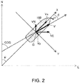
- Fig. 2 is a view illustrating a concept of calculating an estimated position of the first embodiment of the present disclosure.
- a course estimating device 10 includes a current position calculating part 20, an angular velocity calculating part 30, an attitude angle calculating part 40, a ground course calculating part 50, a ground ship speed calculating part 60, a horizontal ground speed calculating part 70, and an estimated position calculating part 80.
- the current position calculating part 20 may calculate a current position P of a movable body to which the course estimating device 10 is provided.
- a current position P(0) may have a latitude component Plat(0) and a longitude component Plon(0).
- the current position calculating part 20 may calculate a current position Pec(0) in the ECEF rectangular coordinate system, for example, by using a code pseudorange etc. of a positioning signal.
- the current position calculating part 20 may calculate a current position Pec(0) using the positioning signal received by at least one antenna which is mounted to a hull.
- the current position calculating part 20 may convert, using a coordinate conversion matrix of the ECEF rectangular coordinate system and an ENU coordinate system, the current position Pec(0) in the ECEF rectangular coordinate system into the current position P in the ENU coordinate system, and calculate the latitude component Plat(0) and the longitude component Plon(0) of the current position P.
- the current position calculating part 20 may output the current position P(0) to the estimated position calculating part 80.
- the angular velocity calculating part 30 calculates an angular velocity ⁇ (t) of the hull.
- the angular velocity calculating part 30 is, as one example, a gyroscope sensor which is an inertia sensor, and measures and outputs the angular velocity ⁇ (t).
- the angular velocity calculating part 30 may calculate the angular velocity ⁇ using a carrier phase difference between the positioning signals.
- the angular velocity calculating part 30 may calculate the angular velocity ⁇ (t) using a difference between the carrier phases received by at least two antennas disposed at different positions of the movable body.
- the angular velocity calculating part 30 may output the angular velocity ⁇ (t) to the estimated position calculating part 80.
- the attitude angle calculating part 40 may calculate an attitude angle of the hull.
- the attitude angle may be normally comprised of a pitch angle ⁇ (t), a roll angle ⁇ (t), and yaw angle ⁇ (t).
- the attitude angle calculating part 40 may calculate at least the yaw angle ⁇ (t).
- the attitude angle calculating part 40 may calculate the attitude angle including at least yaw angle ⁇ (t) by using the angular velocity calculating part 30 and the measurement value or carrier phase difference of the inertia sensor. Note that the attitude angle calculating part 40 may calculate the yaw angle ⁇ (t) based on the angular velocity calculated by the angular velocity calculating part 30. By using the carrier phase, the highly-accurate attitude angle can be acquired with the simple configuration.
- the ground course calculating part 50 may calculate a ground course COG(t) using the attitude angle etc. of the hull.
- the ground course calculating part 50 may output the ground course COG(t) to the horizontal ground speed calculating part 70.
- the ground ship speed calculating part 60 may calculate a ground speed SOG(t) using an output etc. of a Doppler sonar.
- the ground ship speed calculating part 60 may output the ground speed SOG(t) to the horizontal ground speed calculating part 70.
- the horizontal ground speed calculating part 70 calculates a horizontal ground speed Vb(t) in a hull coordinate system using the following method.
- the horizontal ground speed Vb(t) may be a vector quantity, and is comprised of an x-direction component Vbx(t) and a y-direction component Vby(t).
- the x-direction may be a component parallel to the bow direction of a ship 100 as illustrated in Fig. 2 , and a direction from the stern to the bow may be the positive direction.
- the y-direction may be perpendicular to the bow direction (x-direction), and a direction from the port to the starboard may be the positive direction.
- the x-direction component Vbx(t) and the y-direction component Vby(t) of the horizontal ground speed Vb(t) may be obtained from the following formula, where the drift angle is ⁇ (t).
- Vbx t SOG t ⁇ cos ⁇ ⁇ t
- Vby t SOG t ⁇ sin ⁇ ⁇ t
- the drift angle ⁇ may be obtained from the ground course COG and the yaw angle ⁇ by using the following formula.
- ⁇ t COG t ⁇ ⁇ t
- the horizontal ground speed calculating part 70 may calculate a horizontal ground speed Vn(t) in the ENU coordinate system using the following formula.
- the horizontal ground speed Vn(t) in the ENU coordinate system (NED coordinate system) and the horizontal ground speed Vb(t) in the hull coordinate system may have a relation in which the yaw angle ⁇ (t) is an angle formed by the two coordinate systems. Therefore, the north direction component VnN(t) and the east direction component VnE(t) of the horizontal ground speed Vn(t) in the ENU coordinate system (NED coordinates system) may be calculated from the x-direction component Vbx(t) and the y-direction component Vby(t) of the horizontal ground speed Vb(t) in the hull coordinate system, and the yaw angle ⁇ (t).
- VnN t Vbx t ⁇ cos ⁇ ⁇ t ⁇ Vby t ⁇ sin ⁇ ⁇ t
- VnE t Vbx t ⁇ sin ⁇ ⁇ t + Vby t ⁇ cos ⁇ ⁇ t
- the estimated position calculating part 80 calculates an estimated position P( ⁇ ) at an estimation time ⁇ using the following method.
- the estimated position calculating part 80 may determine whether the ship 100 is under translation or turning based on the angular velocity ⁇ .
- Plat ⁇ Plat 0 + integration operation
- VnN Plat 0 + VnN 0 ⁇ sin ⁇ / ⁇ ⁇ VnE 0 ⁇ 1 ⁇ cos ⁇ / ⁇
- Plon ⁇ Plon 0 + integration operation
- VnE Plon 0 + VnN 0 ⁇ 1 ⁇ cos ⁇ / ⁇ ⁇ VnE 0 ⁇ sin ⁇ / ⁇
- the estimated position calculating part 80 may calculate the estimated position P( ⁇ ) using the calculation including the integrated value of the angular velocity which is an acceleration in the turning direction, if the ship 100 is turning.
- the estimated position calculating part 80 may calculate the estimated position P( ⁇ ) using the following calculation without using the acceleration (angular velocity), if the ship is during the translation, i.e., the yaw angle ⁇ ( ⁇ ) is below the turning detection threshold.
- Plat ⁇ Plat 0 + VnN 0 ⁇ ⁇
- Plon ⁇ Plon 0 + VnE 0 ⁇ ⁇
- the course estimating device 10 may reduce the unnecessary use of the acceleration term for calculating the estimated position P( ⁇ ), according to the behavior of the ship 100. Therefore, an increase in the error caused by using the acceleration term can be reduced. Therefore, the course estimating device 10 may calculate the estimated position P( ⁇ ) with high precision. Further, if positional information of the hull obtained by the inertia sensor, such as a speed sensor or an angular velocity sensor (hull coordinates from the center-of-gravity position) is present, the positional information may be corrected to the center-of-gravity position of the hull based on the attitude angle of the hull, thereby calculating the estimated position P( ⁇ ) with higher precision.
- Figs. 3(A) to 3(D) are views of simulations of a course estimation result of the course estimating device of this embodiment and course estimating devices of comparative examples.
- Fig. 3(A) illustrates the estimated course by using the configuration of the present application
- Fig. 3(B) illustrates the estimated course by always using the speed and an amount of change in the speed
- Fig. 3(C) illustrates the estimated course by only using the speed
- Fig. 3(D) illustrates the estimated course by always using the speed and the acceleration.
- broken lines illustrate an actual course
- solid lines illustrate the estimated course.
- a difference between the actual course and the estimated course may be reduced by using the configuration of the course estimating device 10 of this embodiment.
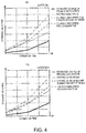
- Figs. 4(A) and 4(B) are views illustrating standard deviations of the estimated course to the actual course between the course estimating device of this embodiment and the course estimating devices of the comparative examples.
- Fig. 4(A) illustrates the standard deviation of the estimated course in latitude
- Fig. 4(B) illustrates the standard deviation of the estimated course in longitude.
- Figs. 4(A) illustrates the standard deviation of the estimated course in latitude
- Fig. 4(B) illustrates the standard deviation of the estimated course in longitude.
- a solid line is the standard deviation of the estimated course of the present application
- a broken line is the standard deviation of the estimated course by only using the speed
- a one-dot chain line is the standard deviation of the estimated course by always using the amount of change of speed and speed
- a two-dot chain line is the standard deviation of the estimated course by always using the speed and the acceleration.
- the standard deviation of the estimated course may be reduced by using the configuration of the course estimating device 10 of this embodiment. That is, the error of the estimated course to the actual course may be reduced.
- the mode in which the processings performed by the course estimating device 10 is realized by a plurality of functional parts is illustrated.
- the plurality of processings are programmed and stored in a storage medium, and this program may be read and executed by a processor, such as a computer.
- the processor may perform processings according to flowcharts illustrated in Figs. 5 and 6 .
- Fig. 5 is a flowchart of the course estimation according to the embodiment of the present disclosure.
- Fig. 6 is a flowchart of the calculation of the estimated position according to the embodiment of the present disclosure. Note that, since the concrete realization method of each processing is the same as the processing of each functional part, description thereof is omitted.
- the processor may calculate the current position P(0) (S11).
- the processor may calculate the angular velocity ⁇ (t).
- the processor may calculate the horizontal ground speed Vn using the yaw angle ⁇ (t) of the attitude angle, the ground course COG(t), and the ground speed SOG(t) (S13).
- the processor may calculate the estimated position P( ⁇ ) using the current position P(0), the angular velocity ⁇ , and the horizontal ground speed Vn( ⁇ ) at the estimation time ⁇ .
- the processor may calculate the estimated position P( ⁇ ) without using the acceleration (S42). If the angular velocity ⁇ greatly differs from 0, i.e., if the processor detects that the angular velocity ⁇ exceeds the turning detection threshold (S41: NO), the processor may calculate the estimated position P( ⁇ ) by the integration operation using the angular velocity which is the acceleration in the turning direction (S43).
- Fig. 7 illustrates a block of the course estimating device according to the second embodiment of the present disclosure.
- a course estimating device 10A according to the second embodiment of the present disclosure differs from the course estimating device 10 according to the first embodiment in that a display unit 90 is added.
- Other configurations of the course estimating device 10A are similar to those of the course estimating device 10, and therefore, description of similar parts is omitted.
- the estimated position calculating part 80 may output the calculated estimated position to the display unit 90.
- the display unit 90 may display this estimated position.
- the estimated position calculating part 80 may output this estimated course to the display unit 90.
- the display unit 90 may display the estimated course.
- attitude angle calculating part 40 the ground course calculating part 50, and the ground ship speed calculating part 60 may be provided separately from the course estimating devices 10 and 10A. Further, the current position calculating part 20 and the angular velocity calculating part 30 may be provided separately from the course estimating devices 10 and 10A.
Landscapes
- Engineering & Computer Science (AREA)
- Radar, Positioning & Navigation (AREA)
- Remote Sensing (AREA)
- Physics & Mathematics (AREA)
- General Physics & Mathematics (AREA)
- Computer Networks & Wireless Communication (AREA)
- Automation & Control Theory (AREA)
- Acoustics & Sound (AREA)
- Navigation (AREA)
- Traffic Control Systems (AREA)
- Measurement Of Velocity Or Position Using Acoustic Or Ultrasonic Waves (AREA)
- Position Fixing By Use Of Radio Waves (AREA)
Abstract
Description
- The present disclosure relates to a course estimating device, a method of estimating a course, and a course estimating program, which estimate a moving position of a movable body.
- Conventionally, various navigation devices having a function for displaying an estimated course has been devised and put in practical use. The conventional navigation devices calculate a distance by multiplying a period of time from the current time point to the estimating time point by the current speed. The conventional navigation devices calculate an estimated position by adding the calculated distance to the current position. Then, the conventional navigation devices calculate the estimated course by successively repeating the calculation of the estimated position.
- As such a navigation device, a navigation device described in Patent Document 1 (a ship display device) calculates the estimated position further using the double integral of acceleration.
- Patent Document 1:
JP0428636B - However, in the navigation device of Patent Document 1, since a value obtained by multiplying 1/2th power value of the square of time by acceleration, noise component caused by the observation error etc. of the acceleration increases. Therefore, errors of the estimated position and the estimated course increase.
- Therefore, one purpose of the present disclosure is to provide a course estimating device, a method of estimating course, and a course estimating program, which calculate an estimated position with high precision.
- A course estimating device of the present disclosure includes a horizontal ground speed calculating part, an angular velocity calculating part and an estimated position calculating part. The horizontal ground speed calculating part calculates a horizontal ground speed based on an attitude angle, a ground course, and a ground ship speed of a movable body. The angular velocity calculating part measures or calculate an angular velocity of the movable body. The estimated position calculating part calculates an estimated position, using a period of time from a current time point to an estimation time point, the horizontal ground speed, and an integration operation of the angular velocity when the angular velocity exceeds a turning detection threshold.
- According to this configuration, the estimated position may be calculated using the integrated value of the acquired angular velocity when the movable body is turning.
- According to the present disclosure, the estimated position can be calculated with high precision.
-
-
Fig. 1 is a block of a course estimating device according to a first embodiment of the present disclosure. -
Fig. 2 is a view illustrating a concept of calculating an estimated position of the first embodiment of the present disclosure. -
Figs. 3(A) to 3(D) are views of simulations of course estimation results of the course estimating device of this embodiment and course estimating devices of comparative examples. -
Figs. 4(A) and 4(B) are views illustrating standard deviations of estimated courses to an actual course between the course estimating device of this embodiment and the course estimating devices of the comparative examples. -
Fig. 5 is a flowchart of course estimation according to the embodiment of the present disclosure. -
Fig. 6 is a flowchart of a calculation of the estimated position according to the embodiment of the present disclosure. -
Fig. 7 is a block of a course estimating device according to a second embodiment of the present disclosure. - A course estimating device, a method of estimating a course, and a course estimating program according to a first embodiment of the present disclosure will be described with reference to the figures. Note that, although a mode in which a ship is used as a movable body is illustrated below, the configuration of the present disclosure invention is also applicable to other water-surface, underwater movable bodies, land movable bodies, or air movable bodies.
-
Fig. 1 illustrates a block of the course estimating device according to the first embodiment of the present disclosure.Fig. 2 is a view illustrating a concept of calculating an estimated position of the first embodiment of the present disclosure. - As illustrated in
Fig. 1 , a course estimatingdevice 10 includes a currentposition calculating part 20, an angularvelocity calculating part 30, an attitudeangle calculating part 40, a groundcourse calculating part 50, a ground shipspeed calculating part 60, a horizontal groundspeed calculating part 70, and an estimatedposition calculating part 80. - The current
position calculating part 20 may calculate a current position P of a movable body to which the course estimatingdevice 10 is provided. A current position P(0) may have a latitude component Plat(0) and a longitude component Plon(0). The currentposition calculating part 20 may calculate a current position Pec(0) in the ECEF rectangular coordinate system, for example, by using a code pseudorange etc. of a positioning signal. The currentposition calculating part 20 may calculate a current position Pec(0) using the positioning signal received by at least one antenna which is mounted to a hull. The currentposition calculating part 20 may convert, using a coordinate conversion matrix of the ECEF rectangular coordinate system and an ENU coordinate system, the current position Pec(0) in the ECEF rectangular coordinate system into the current position P in the ENU coordinate system, and calculate the latitude component Plat(0) and the longitude component Plon(0) of the current position P. The currentposition calculating part 20 may output the current position P(0) to the estimatedposition calculating part 80. - The angular
velocity calculating part 30 calculates an angular velocity ω(t) of the hull. The angularvelocity calculating part 30 is, as one example, a gyroscope sensor which is an inertia sensor, and measures and outputs the angular velocity ω(t). As another example, the angularvelocity calculating part 30 may calculate the angular velocity ω using a carrier phase difference between the positioning signals. In this case, the angularvelocity calculating part 30 may calculate the angular velocity ω(t) using a difference between the carrier phases received by at least two antennas disposed at different positions of the movable body. The angularvelocity calculating part 30 may output the angular velocity ω(t) to the estimatedposition calculating part 80. By using the carrier phase, highly-accurate angular velocity can be obtained with the simple configuration. - The attitude
angle calculating part 40 may calculate an attitude angle of the hull. The attitude angle may be normally comprised of a pitch angle ϕ(t), a roll angle θ(t), and yaw angle ψ(t). The attitudeangle calculating part 40 may calculate at least the yaw angle ψ(t). The attitudeangle calculating part 40 may calculate the attitude angle including at least yaw angle ψ(t) by using the angularvelocity calculating part 30 and the measurement value or carrier phase difference of the inertia sensor. Note that the attitudeangle calculating part 40 may calculate the yaw angle ψ(t) based on the angular velocity calculated by the angularvelocity calculating part 30. By using the carrier phase, the highly-accurate attitude angle can be acquired with the simple configuration. - The ground
course calculating part 50 may calculate a ground course COG(t) using the attitude angle etc. of the hull. The groundcourse calculating part 50 may output the ground course COG(t) to the horizontal groundspeed calculating part 70. - The ground ship
speed calculating part 60 may calculate a ground speed SOG(t) using an output etc. of a Doppler sonar. The ground shipspeed calculating part 60 may output the ground speed SOG(t) to the horizontal groundspeed calculating part 70. - The horizontal ground
speed calculating part 70 calculates a horizontal ground speed Vb(t) in a hull coordinate system using the following method. The horizontal ground speed Vb(t) may be a vector quantity, and is comprised of an x-direction component Vbx(t) and a y-direction component Vby(t). The x-direction may be a component parallel to the bow direction of aship 100 as illustrated inFig. 2 , and a direction from the stern to the bow may be the positive direction. The y-direction may be perpendicular to the bow direction (x-direction), and a direction from the port to the starboard may be the positive direction. - As illustrated in
Fig. 2 , the x-direction component Vbx(t) and the y-direction component Vby(t) of the horizontal ground speed Vb(t) may be obtained from the following formula, where the drift angle is β(t).

- Here, the drift angle β may be obtained from the ground course COG and the yaw angle ψ by using the following formula.

- The horizontal ground
speed calculating part 70 may calculate a horizontal ground speed Vn(t) in the ENU coordinate system using the following formula. - As illustrated in
Fig. 2 , the horizontal ground speed Vn(t) in the ENU coordinate system (NED coordinate system) and the horizontal ground speed Vb(t) in the hull coordinate system may have a relation in which the yaw angle ψ(t) is an angle formed by the two coordinate systems. Therefore, the north direction component VnN(t) and the east direction component VnE(t) of the horizontal ground speed Vn(t) in the ENU coordinate system (NED coordinates system) may be calculated from the x-direction component Vbx(t) and the y-direction component Vby(t) of the horizontal ground speed Vb(t) in the hull coordinate system, and the yaw angle ψ(t).

- The horizontal ground
speed calculating part 70 may output the horizontal ground speed in the ENU coordinate system [Vn(t) = (VnN(t), VnE(t))] to the estimatedposition calculating part 80. - The estimated
position calculating part 80 calculates an estimated position P(τ) at an estimation time τ using the following method. - At the time t, the following relations may be established between the estimated position P(t) = (Plat(t), Plon(t)) and the horizontal ground speed Vn(t) = (VnN(t), VnE(t)).


- Moreover, the yaw angle ψ(τ) at the estimation time may be acquired using the yaw angle ψ(0) at the initial time, and the integration operation of the angular velocity ω(t) from the initial time t=0 to the estimation time t=τ. Assuming that the
ship 100 turns at a constant rate, ω(t) may become a constant value ω from the initial time t=0 to the estimation time t=τ. Therefore, the yaw angle ψ(τ) at the estimation time may be acquired by the following formula.
- Moreover, the estimated
position calculating part 80 may determine whether theship 100 is under translation or turning based on the angular velocity ω. The estimatedposition calculating part 80 may calculate P(τ) = (Plat(τ), Plon(τ)) according to each of the cases. - If the ship is turning or the yaw angle ψ(τ) exceeds a turning detection threshold, the estimated
position calculating part 80 may calculate the estimated position P(τ) = (Plat(τ), Plon(τ)) using the integration operations of the estimated position (Formulas 6 and 7).

- That is, the estimated
position calculating part 80 may calculate the estimated position P(τ) using the calculation including the integrated value of the angular velocity which is an acceleration in the turning direction, if theship 100 is turning. - On the other hand, the estimated
position calculating part 80 may calculate the estimated position P(τ) using the following calculation without using the acceleration (angular velocity), if the ship is during the translation, i.e., the yaw angle ψ(τ) is below the turning detection threshold.

- The estimated
position calculating part 80 may output the calculated estimated position P(τ) = (Plat(τ), Plon(τ)). Moreover, the estimatedposition calculating part 80 may continuously perform the calculation of the estimated position P(τ) to calculate the estimated positions P(τ) at a plurality of time points τ. Then, the estimatedposition calculating part 80 may obtain an estimated course by connecting the estimated positions P(τ) at the plurality of time points τ. - By using such a configuration and processing, the
course estimating device 10 may reduce the unnecessary use of the acceleration term for calculating the estimated position P(τ), according to the behavior of theship 100. Therefore, an increase in the error caused by using the acceleration term can be reduced. Therefore, thecourse estimating device 10 may calculate the estimated position P(τ) with high precision. Further, if positional information of the hull obtained by the inertia sensor, such as a speed sensor or an angular velocity sensor (hull coordinates from the center-of-gravity position) is present, the positional information may be corrected to the center-of-gravity position of the hull based on the attitude angle of the hull, thereby calculating the estimated position P(τ) with higher precision. -
Figs. 3(A) to 3(D) are views of simulations of a course estimation result of the course estimating device of this embodiment and course estimating devices of comparative examples.Fig. 3(A) illustrates the estimated course by using the configuration of the present application,Fig. 3(B) illustrates the estimated course by always using the speed and an amount of change in the speed,Fig. 3(C) illustrates the estimated course by only using the speed, andFig. 3(D) illustrates the estimated course by always using the speed and the acceleration. InFigs. 3(A), 3(B), 3(C), and 3(D) , broken lines illustrate an actual course, and solid lines illustrate the estimated course. - As illustrated in
Figs. 3(A), 3(B), 3(C), and 3(D) , a difference between the actual course and the estimated course may be reduced by using the configuration of thecourse estimating device 10 of this embodiment. -
Figs. 4(A) and 4(B) are views illustrating standard deviations of the estimated course to the actual course between the course estimating device of this embodiment and the course estimating devices of the comparative examples.Fig. 4(A) illustrates the standard deviation of the estimated course in latitude, andFig. 4(B) illustrates the standard deviation of the estimated course in longitude. InFigs. 4(A) and (B) , a solid line is the standard deviation of the estimated course of the present application, and a broken line is the standard deviation of the estimated course by only using the speed, a one-dot chain line is the standard deviation of the estimated course by always using the amount of change of speed and speed, and a two-dot chain line is the standard deviation of the estimated course by always using the speed and the acceleration. - As illustrated in
Figs. 4(A), 4(B), 4(C), and 4(D) , the standard deviation of the estimated course may be reduced by using the configuration of thecourse estimating device 10 of this embodiment. That is, the error of the estimated course to the actual course may be reduced. - Note that in the above description, the mode in which the processings performed by the
course estimating device 10 is realized by a plurality of functional parts is illustrated. However, the plurality of processings are programmed and stored in a storage medium, and this program may be read and executed by a processor, such as a computer. In this case, the processor may perform processings according to flowcharts illustrated inFigs. 5 and6 . -
Fig. 5 is a flowchart of the course estimation according to the embodiment of the present disclosure.Fig. 6 is a flowchart of the calculation of the estimated position according to the embodiment of the present disclosure. Note that, since the concrete realization method of each processing is the same as the processing of each functional part, description thereof is omitted. - As illustrated in
Fig. 5 , the processor may calculate the current position P(0) (S11). The processor may calculate the angular velocity ω(t). The processor may calculate the horizontal ground speed Vn using the yaw angle ψ(t) of the attitude angle, the ground course COG(t), and the ground speed SOG(t) (S13). The processor may calculate the estimated position P(τ) using the current position P(0), the angular velocity ω, and the horizontal ground speed Vn(τ) at the estimation time τ. - In detail, as illustrated in
Fig. 6 , if the angular velocity ω is substantially 0, i.e., if the processor detects that the angular velocity ω is below the turning detection threshold (S41: YES), the processor may calculate the estimated position P(τ) without using the acceleration (S42). If the angular velocity ω greatly differs from 0, i.e., if the processor detects that the angular velocity ω exceeds the turning detection threshold (S41: NO), the processor may calculate the estimated position P(τ) by the integration operation using the angular velocity which is the acceleration in the turning direction (S43). - Next, a course estimating device, a method of estimating the course, and a course estimating program according to a second embodiment will be described with reference to the figure.
Fig. 7 illustrates a block of the course estimating device according to the second embodiment of the present disclosure. - As illustrated in
Fig. 7 , acourse estimating device 10A according to the second embodiment of the present disclosure differs from thecourse estimating device 10 according to the first embodiment in that adisplay unit 90 is added. Other configurations of thecourse estimating device 10A are similar to those of thecourse estimating device 10, and therefore, description of similar parts is omitted. - The estimated
position calculating part 80 may output the calculated estimated position to thedisplay unit 90. Thedisplay unit 90 may display this estimated position. Moreover, when the estimated course is calculated, the estimatedposition calculating part 80 may output this estimated course to thedisplay unit 90. Thedisplay unit 90 may display the estimated course. - By having such a configuration, an operator can visually recognize the estimated position and the estimated course easily.
- Note that the attitude
angle calculating part 40, the groundcourse calculating part 50, and the ground shipspeed calculating part 60 may be provided separately from thecourse estimating devices position calculating part 20 and the angularvelocity calculating part 30 may be provided separately from thecourse estimating devices -
- 10, 10A:
- Course Estimating Device
- 20:
- Current Position Calculating Part
- 30:
- Angular Velocity Calculating Part
- 40:
- Attitude Angle Calculating Part
- 50:
- Ground Course Calculating Part
- 60:
- Ground Ship Speed Calculating Part
- 70:
- Horizontal Ground Speed Calculating Part
- 80:
- Estimated Position Calculating Part
- 90:
- Display Unit
- 100:
- Ship
Claims (20)
- A course estimating device, comprising:a horizontal ground speed calculating part configured to calculate a horizontal ground speed based on an attitude angle, a ground course, and a ground ship speed of a movable body;an angular velocity calculating part configured to measure or calculate an angular velocity of the movable body; andan estimated position calculating part configured to calculate an estimated position, using a period of time from a current time point to an estimation time point, the horizontal ground speed, and an integration operation of the angular velocity when the angular velocity exceeds the turning detection threshold.
- The course estimating device of claim 1, wherein the estimated position calculating part calculates the estimated position without using the angular velocity, when the angular velocity is below the turning detection threshold.
- The course estimating device of claim 1 or 2, comprising an attitude angle calculating part configured to calculate the attitude angle using carrier phases of positioning signals.
- The course estimating device of any one of claims 1 to 3, comprising a ground course calculating part configured to calculate the ground course using carrier phases of positioning signals.
- The course estimating device of claim 3, wherein the attitude angle calculating part calculates at least a yaw angle of the attitude angle.
- The course estimating device of any one of claims 1 to 5, wherein the angular velocity calculating part calculates the angular velocity using carrier phases of positioning signals or an output of an inertia sensor.
- The course estimating device of any one of claims 1 to 6, wherein the estimated position calculating part calculates the estimated positions at a plurality of estimation time points, and calculates the estimated course connecting the estimated positions.
- The course estimating device of claim 7, comprising a display unit configured to display the estimated position and the estimated course.
- A method of estimating a course, comprising the steps of:calculating a horizontal ground speed based on an attitude angle, a ground course, and a ground ship speed of a movable body;measuring or calculating an angular velocity of the movable body; andcalculating an estimated position, using a period of time from a current time point to an estimation time point, the horizontal ground speed, and an integration operation of the angular velocity when the angular velocity exceeds a turning detection threshold.
- The method of claim 9, wherein the calculating the estimated position includes calculating the estimated position without using the angular velocity, when the angular velocity is below the turning detection threshold.
- The method of claim 9 or 10, wherein the attitude angle is calculated using carrier phases of positioning signals.
- The method of any one of claims 9 to 11, wherein the ground course is calculated using carrier phases of positioning signals.
- The method of claim 11, wherein the calculating the attitude angle includes calculating at least a yaw angle of the attitude angle.
- The method of any one of claims 9 to 13, wherein the calculating the angular velocity includes calculating the angular velocity using carrier phases of positioning signals or an output of an inertia sensor.
- A course estimating program configured to cause a processor to execute processings, the processings comprising:calculating a horizontal ground speed based on an attitude angle, a ground course, and a ground ship speed of a movable body;measuring or calculating an angular velocity of the movable body; andcalculating an estimated position, using a period of time from a current time point to an estimation time point, the horizontal ground speed, and an integration operation of the angular velocity when the angular velocity exceeds a turning detection threshold.
- The course estimating program of claim 15, wherein the calculating the estimated position includes calculating the estimated position without using the angular velocity, when the angular velocity is below the turning detection threshold.
- The course estimating program of claim 15 or 16, wherein the attitude angle is calculated using carrier phases of positioning signals.
- The course estimating program of any one of claims 15 to 17, wherein the ground course is calculated using carrier phases of positioning signals.
- The course estimating program of claim 17, wherein the calculating the attitude angle includes calculating at least a yaw angle of the attitude angle.
- The course estimating program of any one of claims 15 to 19, wherein the calculating the angular velocity includes calculating the angular velocity using carrier phases of positioning signals or an output of an inertia sensor.
Applications Claiming Priority (2)
| Application Number | Priority Date | Filing Date | Title |
|---|---|---|---|
| JP2017128510 | 2017-06-30 | ||
| PCT/JP2018/020513 WO2019003758A1 (en) | 2017-06-30 | 2018-05-29 | Track prediction device, track prediction method, and track prediction program |
Publications (2)
| Publication Number | Publication Date |
|---|---|
| EP3647817A1 true EP3647817A1 (en) | 2020-05-06 |
| EP3647817A4 EP3647817A4 (en) | 2021-01-27 |
Family
ID=64740593
Family Applications (1)
| Application Number | Title | Priority Date | Filing Date |
|---|---|---|---|
| EP18825136.7A Withdrawn EP3647817A4 (en) | 2017-06-30 | 2018-05-29 | Track prediction device, track prediction method, and track prediction program |
Country Status (5)
| Country | Link |
|---|---|
| US (1) | US11255675B2 (en) |
| EP (1) | EP3647817A4 (en) |
| JP (1) | JP6808835B2 (en) |
| CN (1) | CN110832342A (en) |
| WO (1) | WO2019003758A1 (en) |
Family Cites Families (11)
| Publication number | Priority date | Publication date | Assignee | Title |
|---|---|---|---|---|
| JPS60111214U (en) * | 1983-12-29 | 1985-07-27 | 横河電機株式会社 | navigation equipment |
| JPS6428197A (en) * | 1987-07-21 | 1989-01-30 | Kito Kk | Truck crane |
| WO1993007448A1 (en) | 1991-10-04 | 1993-04-15 | Furuno Electric Company, Limited | Display apparatus |
| JP4528636B2 (en) * | 2005-01-17 | 2010-08-18 | 日本無線株式会社 | Marine display device |
| JP4321554B2 (en) * | 2006-06-23 | 2009-08-26 | トヨタ自動車株式会社 | Attitude angle detection device and attitude angle detection method |
| JP2009115514A (en) * | 2007-11-02 | 2009-05-28 | Seiko Epson Corp | Positioning method, program, positioning circuit and electronic device |
| KR101314308B1 (en) * | 2010-02-26 | 2013-10-02 | 한국전자통신연구원 | Apparatus for managing traffic using previous navigational preference patterns based navigational situation and method thereof |
| JP5614527B2 (en) * | 2010-03-05 | 2014-10-29 | セイコーエプソン株式会社 | Attitude information calculation apparatus, attitude information calculation system, attitude information calculation method, and attitude information calculation program |
| JP5419784B2 (en) * | 2010-04-06 | 2014-02-19 | 三菱電機株式会社 | Prediction device, prediction system, computer program, and prediction method |
| JP2014145614A (en) * | 2013-01-28 | 2014-08-14 | Furuno Electric Co Ltd | Turning round angular speed detection device, moving body, turning round angular speed detecting method, and turning round angular speed detection program |
| JP6310202B2 (en) * | 2013-07-24 | 2018-04-11 | 古野電気株式会社 | State calculation device, moving body, state calculation method, and state calculation program |
-
2018
- 2018-05-29 CN CN201880041335.4A patent/CN110832342A/en active Pending
- 2018-05-29 EP EP18825136.7A patent/EP3647817A4/en not_active Withdrawn
- 2018-05-29 WO PCT/JP2018/020513 patent/WO2019003758A1/en not_active Ceased
- 2018-05-29 JP JP2019526709A patent/JP6808835B2/en active Active
-
2019
- 2019-12-27 US US16/728,420 patent/US11255675B2/en active Active
Also Published As
| Publication number | Publication date |
|---|---|
| CN110832342A (en) | 2020-02-21 |
| US11255675B2 (en) | 2022-02-22 |
| EP3647817A4 (en) | 2021-01-27 |
| JP6808835B2 (en) | 2021-01-06 |
| JPWO2019003758A1 (en) | 2020-04-09 |
| WO2019003758A1 (en) | 2019-01-03 |
| US20200200539A1 (en) | 2020-06-25 |
Similar Documents
| Publication | Publication Date | Title |
|---|---|---|
| US9342075B2 (en) | Apparatus, method and computer readable media for calculating status, and movable body | |
| US10197681B2 (en) | State calculating device, method of calculating state, and state calculating program | |
| US10514469B2 (en) | Attitude angle calculating device, method of calculating attitude angle, and attitude angle calculating program | |
| US20140267686A1 (en) | System and method for augmenting a gnss/ins navigation system of a low dynamic vessel using a vision system | |
| EP4349707A1 (en) | Vessel navigation assistance device, vessel navigation assistance method, and vessel navigation assistance program | |
| US7355549B2 (en) | Apparatus and method for carrier phase-based relative positioning | |
| US20240175984A1 (en) | Information processing device, control method, program, and storage medium | |
| US10948292B2 (en) | Sensor error calculating device, attitude angle calculating apparatus, method of calculating sensor error and method of calculating attitude angle | |
| CN108344426B (en) | Course angle deviation estimation method between water surface/underwater vehicle and positioning equipment | |
| KR101763911B1 (en) | Heading estimation apparatus of auv in severe magnetic disturbance environment and the method thereof | |
| US12546604B2 (en) | Information processing device, control method, program, and storage medium | |
| CN118816891B (en) | Non-integrity constraint assisted SINS/EML integrated navigation method, program, equipment and storage medium | |
| EP3647817A1 (en) | Track prediction device, track prediction method, and track prediction program | |
| EP4737856A1 (en) | Automatic docking device, automatic docking system, automatic docking method, and automatic docking program | |
| JP6321914B2 (en) | Mobile body information calculation device, mobile body information acquisition device, mobile body, mobile body information calculation method, mobile body information acquisition method, mobile body information calculation program, and mobile body information acquisition program | |
| JP2528833B2 (en) | Wharf controller | |
| JP3192448B2 (en) | Tide meter | |
| CN114993313B (en) | Trajectory calculation and registration method based on autonomous underwater robot inertial navigation and ultra-short baseline positioning sensor | |
| Bustos et al. | Matching radar and satellite images for ship trajectory estimation using the Hausdorff distance | |
| JP2994111B2 (en) | Tide meter | |
| CN113175924B (en) | Vehicle heading information based on single satellite detection | |
| Torres-Torriti et al. | Automatic ship positioning and radar biases correction using the hausdorff distance | |
| CN114397648A (en) | Photoelectric detection auxiliary positioning method and positioning system based on sea chart object | |
| CN117516539A (en) | An unmanned ship positioning method, device, equipment and medium | |
| CN121632160A (en) | A Single-Beacon Range-Circle Positioning-Assisted INS Navigation Method Based on Mahalanobis Distance Constraints |
Legal Events
| Date | Code | Title | Description |
|---|---|---|---|
| STAA | Information on the status of an ep patent application or granted ep patent |
Free format text: STATUS: THE INTERNATIONAL PUBLICATION HAS BEEN MADE |
|
| PUAI | Public reference made under article 153(3) epc to a published international application that has entered the european phase |
Free format text: ORIGINAL CODE: 0009012 |
|
| STAA | Information on the status of an ep patent application or granted ep patent |
Free format text: STATUS: REQUEST FOR EXAMINATION WAS MADE |
|
| 17P | Request for examination filed |
Effective date: 20200109 |
|
| AK | Designated contracting states |
Kind code of ref document: A1 Designated state(s): AL AT BE BG CH CY CZ DE DK EE ES FI FR GB GR HR HU IE IS IT LI LT LU LV MC MK MT NL NO PL PT RO RS SE SI SK SM TR |
|
| AX | Request for extension of the european patent |
Extension state: BA ME |
|
| DAV | Request for validation of the european patent (deleted) | ||
| DAX | Request for extension of the european patent (deleted) | ||
| RIC1 | Information provided on ipc code assigned before grant |
Ipc: G01C 21/16 20060101ALI20201217BHEP Ipc: G01S 19/54 20100101ALI20201217BHEP Ipc: G01S 19/49 20100101AFI20201217BHEP Ipc: G01S 15/60 20060101ALI20201217BHEP Ipc: G01S 19/42 20100101ALI20201217BHEP |
|
| A4 | Supplementary search report drawn up and despatched |
Effective date: 20210111 |
|
| STAA | Information on the status of an ep patent application or granted ep patent |
Free format text: STATUS: THE APPLICATION IS DEEMED TO BE WITHDRAWN |
|
| 18D | Application deemed to be withdrawn |
Effective date: 20210810 |