EP3647802A1 - Storage battery remaining quantity estimation device, storage battery remaining quantity estimation method, and program - Google Patents
Storage battery remaining quantity estimation device, storage battery remaining quantity estimation method, and program Download PDFInfo
- Publication number
- EP3647802A1 EP3647802A1 EP17915535.3A EP17915535A EP3647802A1 EP 3647802 A1 EP3647802 A1 EP 3647802A1 EP 17915535 A EP17915535 A EP 17915535A EP 3647802 A1 EP3647802 A1 EP 3647802A1
- Authority
- EP
- European Patent Office
- Prior art keywords
- soc
- value
- storage battery
- correction amount
- current
- Prior art date
- Legal status (The legal status is an assumption and is not a legal conclusion. Google has not performed a legal analysis and makes no representation as to the accuracy of the status listed.)
- Granted
Links
Images




Classifications
-
- G—PHYSICS
- G01—MEASURING; TESTING
- G01R—MEASURING ELECTRIC VARIABLES; MEASURING MAGNETIC VARIABLES
- G01R31/00—Arrangements for testing electric properties; Arrangements for locating electric faults; Arrangements for electrical testing characterised by what is being tested not provided for elsewhere
- G01R31/36—Arrangements for testing, measuring or monitoring the electrical condition of accumulators or electric batteries, e.g. capacity or state of charge [SoC]
- G01R31/367—Software therefor, e.g. for battery testing using modelling or look-up tables
-
- G—PHYSICS
- G01—MEASURING; TESTING
- G01R—MEASURING ELECTRIC VARIABLES; MEASURING MAGNETIC VARIABLES
- G01R31/00—Arrangements for testing electric properties; Arrangements for locating electric faults; Arrangements for electrical testing characterised by what is being tested not provided for elsewhere
- G01R31/36—Arrangements for testing, measuring or monitoring the electrical condition of accumulators or electric batteries, e.g. capacity or state of charge [SoC]
- G01R31/385—Arrangements for measuring battery or accumulator variables
- G01R31/387—Determining ampere-hour charge capacity or SoC
- G01R31/388—Determining ampere-hour charge capacity or SoC involving voltage measurements
-
- G—PHYSICS
- G01—MEASURING; TESTING
- G01R—MEASURING ELECTRIC VARIABLES; MEASURING MAGNETIC VARIABLES
- G01R31/00—Arrangements for testing electric properties; Arrangements for locating electric faults; Arrangements for electrical testing characterised by what is being tested not provided for elsewhere
- G01R31/36—Arrangements for testing, measuring or monitoring the electrical condition of accumulators or electric batteries, e.g. capacity or state of charge [SoC]
- G01R31/3644—Constructional arrangements
- G01R31/3648—Constructional arrangements comprising digital calculation means, e.g. for performing an algorithm
-
- G—PHYSICS
- G01—MEASURING; TESTING
- G01R—MEASURING ELECTRIC VARIABLES; MEASURING MAGNETIC VARIABLES
- G01R31/00—Arrangements for testing electric properties; Arrangements for locating electric faults; Arrangements for electrical testing characterised by what is being tested not provided for elsewhere
- G01R31/36—Arrangements for testing, measuring or monitoring the electrical condition of accumulators or electric batteries, e.g. capacity or state of charge [SoC]
- G01R31/374—Arrangements for testing, measuring or monitoring the electrical condition of accumulators or electric batteries, e.g. capacity or state of charge [SoC] with means for correcting the measurement for temperature or ageing
-
- G—PHYSICS
- G01—MEASURING; TESTING
- G01R—MEASURING ELECTRIC VARIABLES; MEASURING MAGNETIC VARIABLES
- G01R31/00—Arrangements for testing electric properties; Arrangements for locating electric faults; Arrangements for electrical testing characterised by what is being tested not provided for elsewhere
- G01R31/36—Arrangements for testing, measuring or monitoring the electrical condition of accumulators or electric batteries, e.g. capacity or state of charge [SoC]
- G01R31/382—Arrangements for monitoring battery or accumulator variables, e.g. SoC
-
- H—ELECTRICITY
- H02—GENERATION; CONVERSION OR DISTRIBUTION OF ELECTRIC POWER
- H02J—ELECTRIC POWER NETWORKS; CIRCUIT ARRANGEMENTS OR SYSTEMS FOR SUPPLYING OR DISTRIBUTING ELECTRIC POWER; SYSTEMS FOR STORING ELECTRIC ENERGY
- H02J7/00—Circuit arrangements for charging or discharging batteries or for supplying loads from batteries
- H02J7/50—Circuit arrangements for charging or discharging batteries or for supplying loads from batteries acting upon multiple batteries simultaneously or sequentially
-
- H—ELECTRICITY
- H02—GENERATION; CONVERSION OR DISTRIBUTION OF ELECTRIC POWER
- H02J—ELECTRIC POWER NETWORKS; CIRCUIT ARRANGEMENTS OR SYSTEMS FOR SUPPLYING OR DISTRIBUTING ELECTRIC POWER; SYSTEMS FOR STORING ELECTRIC ENERGY
- H02J7/00—Circuit arrangements for charging or discharging batteries or for supplying loads from batteries
- H02J7/80—Circuit arrangements for charging or discharging batteries or for supplying loads from batteries including monitoring or indicating arrangements
- H02J7/82—Control of state of charge [SOC]
-
- G—PHYSICS
- G01—MEASURING; TESTING
- G01R—MEASURING ELECTRIC VARIABLES; MEASURING MAGNETIC VARIABLES
- G01R31/00—Arrangements for testing electric properties; Arrangements for locating electric faults; Arrangements for electrical testing characterised by what is being tested not provided for elsewhere
- G01R31/36—Arrangements for testing, measuring or monitoring the electrical condition of accumulators or electric batteries, e.g. capacity or state of charge [SoC]
- G01R31/382—Arrangements for monitoring battery or accumulator variables, e.g. SoC
- G01R31/3842—Arrangements for monitoring battery or accumulator variables, e.g. SoC combining voltage and current measurements
Definitions
- Embodiments of the present invention relate to a remaining battery energy estimation device, a remaining battery energy estimation method, and a program.
- SOC state of charge
- Non-Patent Literature 1 Various methods for estimating the SOC of a storage battery are known (see Non-Patent Literature 1). Examples include an actual measurement method of actually causing discharge and integrating a current value of the storage battery until discharge is completed, an open circuit voltage (OCV) method of obtaining an SOC from an OCV during a current pause period on the basis of the relationship between the SOC and the OCV, a current integration method of integrating the current value to obtain an SOC change ( ⁇ SOC) over a certain period of time, and a closed circuit voltage (CCV) method of estimating the SOC from information such as voltage, current, and temperature during charging/discharging using an equivalent circuit model of the storage battery.
- OCV open circuit voltage
- ⁇ SOC SOC change
- CCV closed circuit voltage
- the actual measurement method is difficult to use during operation and its practical value is low since actual measurement changes the SOC itself.
- the OCV method is difficult to apply to a system that does not have a pause period (or cannot guarantee the presence of a pause period).
- steady-state errors in current measurement values may be accumulated, resulting in a large estimation error.
- the CCV method is more practical relative to other methods, but as long as there is a characteristic difference between the equivalent circuit model of the storage battery and the actual storage battery, an SOC estimation error corresponding to the difference will occur. This error appears especially during a transient response when the current or SOC changes greatly.
- Patent Literature 1 has a function of correcting a steady-state error in a current measurement value.
- the technique described in Patent Literature 1 has a problem that a residual error in a current offset that is uncorrectable cannot be corrected.
- Patent Literature 3 In the technique described in Patent Literature 3, a steady-state error in a current measurement value and a full charge capacity error together are estimated through periodic processing. However, the technique described in Patent Literature 3 has a problem that a processing load is great.
- the Kalman filter is configured such that the error between the estimated SOC value based on the OCV method and the estimated SOC value based on the current integration method is small.
- the error may increase depending on the current waveform.
- It is an object of the present invention is to provide a remaining battery energy estimation device, a remaining battery energy estimation method, and a program that can estimate the SOC of a storage battery with high accuracy while suppressing a processing load.
- a remaining battery energy estimation device includes a current corrector, an SOC calculator, a voltage estimator, an SOC correction amount determiner, and a current error estimator.
- the current corrector determines a corrected current value on the basis of a current value and a current correction amount of a storage battery.
- the SOC calculator calculates an estimated SOC value of the storage battery on the basis of the corrected current value and an SOC correction amount.
- the voltage estimator determines an estimated voltage value of the storage battery on the basis of a temperature value of the storage battery, the corrected current value, and the estimated SOC value.
- the SOC correction amount determiner determines the SOC correction amount on the basis of a comparison between a voltage value of the storage battery and the estimated voltage value.
- the current error estimator determines the current correction amount on the basis of the SOC correction amount.
- the remaining battery energy estimation device is a device for estimating the SOC, which is the remaining amount (or charge rate) of a storage battery (secondary battery), with high accuracy while operating the storage battery.
- the storage battery to be estimated may be a battery cell as a minimum unit, a battery pack in which battery cells are combined in series, parallel, or series-parallel, or a battery pack unit in which battery packs are combined in series, parallel, or series-parallel. The following description will be given assuming that the storage battery to be estimated is a battery cell.
- Fig. 1 is a functional configuration diagram of a remaining battery energy estimation device 100 according to a first embodiment.
- the remaining battery energy estimation device 100 includes, for example, a current corrector 110, an SOC calculator 120, a voltage estimator 130, an SOC correction amount determiner 140, and a current error estimator 150.
- These components are realized by a processor such as a central processing unit (CPU) executing a program (software). Some or all of these components may be realized by hardware (circuitry) such as a large scale integration (LSI), an application specific integrated circuit (ASIC), or a field-programmable gate array (FPGA) or may be realized by hardware and software in cooperation.
- LSI large scale integration
- ASIC application specific integrated circuit
- FPGA field-programmable gate array
- Measurement values such as a voltage value Vin, a temperature value Tin, and a current value Iin measured by sensors attached in the vicinity of a battery for remaining amount estimation are input to the remaining battery energy estimation device 100.
- Values such as a default correction amount ⁇ Idf, a full charge capacity C, and a default SOC value SOCdf are given to the remaining battery energy estimation device 100.
- These values may be stored in a storage device such as a read only memory (ROM), a random access memory (RAM), a register, a flash memory, or a hard disk drive (HDD), or may be given from an external device (for example, an upper control device) as necessary.
- ROM read only memory
- RAM random access memory
- HDD hard disk drive
- illustration of hardware such as input terminals through which measurement values are input is omitted.
- the current corrector 110 determines a corrected current value I* on the basis of the current value Iin that is a measurement value and a current correction amount ⁇ I. For example, the current corrector 110 determines the corrected current value I* by adding (or subtracting) the current correction amount ⁇ I to (or from) the current value Iin. The current corrector 110 determines the corrected current value I* using the default correction amount ⁇ Idf instead of the current correction amount ⁇ I when the current correction amount ⁇ I has not been obtained such as at the start of operation of the remaining battery energy estimation device 1.
- the corrected current value I* is output to the SOC calculator 120 and the voltage estimator 130.
- "output" is a convenient expression and may refer to, for example, an operation of writing target data in a memory area that can be referred to by both an input operator and an output operator.
- the SOC calculator 120 calculates SOC#, which is an estimated SOC value of the storage battery, on the basis of the corrected current value I* and the SOC correction amount ⁇ SOC. For example, the SOC calculator 120 calculates the estimated SOC value SOC# on the basis of the full charge capacity Cmax and the default SOC value SOCdf of the storage battery in addition to the corrected current value I* and the SOC correction amount ⁇ SOC.
- Fig. 2 is a diagram illustrating an example of a functional configuration of the SOC calculator 120.
- the SOC calculator 120 includes, for example, an integration processor 122 and an adder 124.
- the integration processor 122 divides a value obtained by integrating the corrected current value I* by the full charge capacity C and then adds a previous estimated SOC value SOC# (initially, the default value SOCdf) to it and then outputs the resulting value to the adder 124.
- the adder 124 adds the value input from the integration processor 122 and the SOC correction amount ⁇ SOC to calculate a present estimated SOC value SOC#.
- the default SOC value SOCdf is, for example, a value estimated by an OCV method.
- the default SOC value SOCdf is derived, for example, at the start of operation of a storage battery system (which will be described later) that is to be processed by the remaining battery energy estimation device 100.
- the full charge capacity C is set to an initial capacity at the time of shipment of the storage battery system from a factory and thereafter updated as needed on the basis of an actual measurement value in a periodic inspection, an estimated value during operation, or the like.
- the content of processing performed by the SOC calculator 120 is expressed by Expression (1).
- (n) indicates that the value is calculated in an nth cycle while the remaining battery energy estimation device 100 iteratively performs processing.
- SOC#(0) SOCdf.
- Ts is the processing cycle of the iterative processing.
- SOC # n + 1 SOC # n + 1 ⁇ n ⁇ Ts 3600 ⁇ 1 C ⁇ 100 + ⁇ ⁇ SOC n
- the voltage estimator 130 outputs an estimated voltage value V# of the storage battery on the basis of the temperature value Tin, the corrected current value I*, and the estimated SOC value SOC#.
- the voltage estimator 130 derives the estimated voltage value V# of the storage battery by applying the above data to an equivalent circuit model of the storage battery.
- the voltage estimator 130 derives the estimated voltage value V# of the storage battery, for example, on the basis of the relationship between the voltage and the estimated SOC value SOC# that depends on the temperature value Tin and a voltage fluctuation amount based on an internal resistance and the corrected current value I*.
- Fig. 3 is a diagram illustrating an example of a functional configuration of the current error estimator 150.
- the current error estimator 150 determines a current correction amount ⁇ I on the basis of the SOC correction amount ⁇ SOC.
- the current error estimator 150 includes, for example, a time integrator 152, a time measuring unit 154, and a divider 156.
- the time integrator 152 integrates a value indicated by the input SOC correction amount ⁇ SOC.
- the time measuring unit 154 measures the time during which the time integrator 152 performs integration.
- the divider 156 divides the integration result of the time integrator 152 by the time measured by the time measuring unit 154 to derive the current correction amount ⁇ I.
- the SOC calculator 120, the voltage estimator 130, and the SOC correction amount determiner 140 perform operations similar to a Kalman filter as a whole and correct the SOC such that the estimated voltage value V# output by the voltage estimator 130 matches the voltage value Vin.
- the estimated SOC value SOC# output by the SOC calculator 120 is expected to match the actual SOC.
- the gain Gk of the SOC correction amount determiner 140 is a small fixed value as will be described later. This is because a current offset error is basically assumed as an error factor of the estimated voltage value V#, and in the first embodiment, correction is performed such that the current offset error decreases.
- the current offset error is a steady-state error that occurs in the sensor that measures the current value Iin.
- Other error factors of the estimated voltage value V# include self-discharge of the storage battery and discharge by a cell balance circuit although the influence thereof upon SOC estimation is smaller than that of the current offset error.
- the current error ⁇ I that the current error estimator 150 has estimated on the basis of the SOC correction amount ⁇ SOC is fed back and added to (or subtracted from) the current value Iin to derive the corrected current value I* and the SOC calculator 120, the voltage estimator 130, and the SOC correction amount determiner 140 perform the above operations using the corrected current value I*.
- the SOC correction amount ⁇ SOC may not match the current offset error in a short term, but the SOC correction amount ⁇ SOC is expected to approach the current offset error stably by obtaining an average value for a long period (for example, a month).
- the gain Gk may be a value within a range determined with reference to the lower limit.
- the gain Gk is preferably set to a value within a range from the lower limit to about 2 to 3 times the lower limit.
- Factors that determine the long-term error include a total current value Ie of error factors (including the current offset error Ioffset) [mA], a slope SL that is an OCV/SOC characteristic (the characteristic of a DOC change with respect to an OCV change) [mV/%], and the capacity Ch of the storage battery [Ah].
- Ie of error factors including the current offset error Ioffset
- SL slope
- SL that is an OCV/SOC characteristic
- the SOC correction amount ⁇ SOC in the steady state is also a steady-state error in the SOC. For this reason, when the upper limit of the SOC correction amount ⁇ SOC is ⁇ SOCmax, the lower limit value of the gain Gk is expressed by the right term of Expression (7). Gk ⁇ 2.8 ⁇ 10 ⁇ 5 ⁇ Ie / Ch ⁇ SL ⁇ ⁇ SOCmax
- ⁇ ⁇ SOC Gk ⁇ ⁇ ⁇ V ⁇ Ts
- the voltage error ⁇ V is a value that fluctuates depending on the system design. Therefore, although it cannot be generally stated, it is assumed in the above expression "the gain Gk is preferably set to a value within a range from the lower limit to about 2 to 3 times the lower limit” that it becomes close to or greater than a "value about 2 to 3 times the lower limit.” Thus, by setting the gain Gk to a value no greater than about 2 to 3 times the lower limit, there is a high probability that the gain Gk can be prevented from exceeding the upper limit value of the gain Gk.
- Fig. 4 is a diagram comparing actual SOC values (true SOC values) and estimated SOC values according to the current integration method when the current integration method is employed. As described above, in the current integration method, steady-state errors in current measurement values may be accumulated, resulting in a large estimation error.
- Fig. 5 is a diagram comparing actual SOC values (true SOC values) and estimated SOC values according to the CCV method when the CCV method is employed.
- an SOC estimation error corresponding to the difference occurs. This error appears especially during a transient response when the current or SOC changes greatly.
- Fig. 6 is a diagram comparing actual SOC values (true SOC values) and estimated SOC values according to the method of the embodiment when the method of the embodiment is adopted. As shown, the method of the embodiment exhibits characteristics that compensate for the shortcomings of the current integration method and the CCV method and thus can reduce both steady-state errors and errors during transient responses.
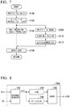
- Fig. 7 is a flowchart showing an example of a flow of a process executed by the remaining battery energy estimation device 100.
- the process of this flowchart is executed iteratively at a predetermined cycle.
- the content of the process is simply shown without considering the processing cycle Ts and the like.
- measurement values such as a voltage value Vin, a temperature value Tin, and a current value Iin are input to the remaining battery energy estimation device 100 (step S100).
- the current corrector 110 calculates a corrected current value I* on the basis of the current value Iin and a current correction amount ⁇ I (initially, ⁇ Idf) calculated in a previous routine of this flowchart (step S102).
- the SOC calculator 120 calculates a present estimated SOC value SOC# on the basis of an estimated SOC value SOC# calculated in the previous routine of this flowchart, the corrected current value I*, and an SOC correction amount ⁇ SOC calculated in the previous routine of this flowchart (step S104).
- the remaining battery energy estimation device 100 outputs the estimated SOC value SOC# calculated in step S104 (step S106).
- the voltage estimator 130 applies the temperature value Tin, the corrected current value I*, and the estimated SOC value SOC# to the equivalent circuit model of the storage battery (represented as a function f in the drawing) to derive an estimated voltage value V# of the storage battery (step S108).
- the SOC correction amount determiner 140 calculates an SOC correction amount ⁇ SOC by multiplying the difference between the voltage value Vin and the estimated voltage value V# by the gain Gk (step S110), and the current error estimator 150 calculates a current correction amount ⁇ I by integrating the SOC correction amount ⁇ SOC (step S112).
- the SOC correction amount ⁇ SOC calculated in step S110 and the current correction amount ⁇ I calculated in step S112 are used in a next routine of this flowchart.
- the current corrector 110 that determines a corrected current value on the basis of a current value and a current correction amount of a storage battery
- the SOC calculator 120 that calculates an estimated SOC value of the storage battery on the basis of the corrected current value and an SOC correction amount
- the voltage estimator 130 that outputs an estimated voltage value of the storage battery on the basis of a temperature value of the storage battery, the corrected current value, and the estimated SOC value
- the SOC correction amount determiner 140 that determines the SOC correction amount on the basis of a comparison between a voltage value of the storage battery and the estimated voltage value
- the current error estimator 150 that determines the current correction amount on the basis of the SOC correction amount
- the current corrector 110 and the current error estimator 150 may be omitted and the SOC correction amount determiner 140 may be replaced with an SOC correction amount determiner 140A described below.
- the current value Iin is input to an SOC calculator 120 and a voltage estimator 130.
- the SOC calculator 120 and the voltage estimator 130 perform the same processing as in the above embodiment with the corrected current value I* replaced with the current value Iin.
- Fig. 8 is a diagram illustrating an example of a functional configuration of the SOC correction amount determiner 140A.
- the SOC correction amount determiner 140A includes, for example, a difference calculator 142, a gain multiplier 144, an integration calculator 146, and an adder 148.
- the difference calculator 142 calculates the difference between the voltage value Vin and the estimated voltage value V#. This difference is represented by e(t).
- the gain multiplier 144 multiplies the difference e(t) by the gain Gk and outputs the result.
- the integration calculator 146 outputs a time integral of the difference e(t) multiplied by a coefficient Gi.
- the adder 148 adds the output of the gain multiplier 144 and the output of the integration calculator 146 and outputs the result as an SOC correction amount ⁇ SOC.
- Fig. 9 is a functional configuration diagram of a remaining battery energy estimation device 100B according to the second embodiment.
- the remaining battery energy estimation device 100B includes, for example, a current corrector 110, an SOC calculator 120, a voltage estimator 130, an SOC correction amount determiner 140, an SOC calculator 120B, a voltage estimator 130B, an SOC correction amount determiner 140B, and a regression analyzer 160.
- These components are realized by a processor such as a CPU executing a program (software). Some or all of these components may be realized by hardware (circuitry) such as an LSI, an ASIC, or an FPGA or may be realized by hardware and software in cooperation.
- Measurement values such as a voltage value Vin, a temperature value Tin, and a current value Iin measured by sensors attached in the vicinity of a battery for remaining amount estimation are input to the remaining battery energy estimation device 100B.
- Values such as a default correction amount ⁇ Idf, a full charge capacity C, and a default SOC value SOCdf are given to the remaining battery energy estimation device 100B.
- These values may be stored in a storage device such as a ROM, a RAM, a register, a flash memory, or an HDD, or may be given from an external device (for example, an upper control device) as necessary.
- a storage device such as a ROM, a RAM, a register, a flash memory, or an HDD, or may be given from an external device (for example, an upper control device) as necessary.
- illustration of hardware such as input terminals through which measurement values are input is omitted.
- the functions of the current corrector 110, the SOC calculator 120, the voltage estimator 130, and the SOC correction amount determiner 140 are the same as those of the first embodiment.
- the functions of the SOC calculator 120B, the voltage estimator 130B, the SOC correction amount determiner 140B, and the regression analyzer 160 will be described.
- the SOC calculator 120B, the voltage estimator 130B, and the SOC correction amount determiner 140B perform the same processing as the SOC calculator 120, the voltage estimator 130, and the SOC correction amount determiner 140 mainly with the corrected current value I* replaced with the current value Iin.
- a gain Ga of the SOC correction amount determiner 140B is greater than the gain Gk of the SOC correction amount determiner 140.
- the gain Ga is greater the gain Gk by more than one order of magnitude.
- the SOC calculator 120B calculates SOC#B, which is the estimated SOC value of the storage battery, on the basis of the current value Iin and the SOC correction amount ⁇ SOC. For example, the SOC calculator 120B calculates the estimated SOC value SOC#B on the basis of the full charge capacity C of the storage battery and the default SOC value SOCdf in addition to the current value Iin and the SOC correction amount ⁇ SOC.
- the functional configuration of the SOC calculator 120B is obtained, for example, by replacing the corrected current value I* in Fig. 2 with the current value Iin.
- the content of processing performed by the SOC calculator 120B is expressed by an expression obtained by replacing I*(n) with Iin(n) in Expression (1).
- the voltage estimator 130B outputs an estimated voltage value V# of the storage battery on the basis of the temperature value Tin, the current value Iin, and the estimated SOC value SOC#B.
- the voltage estimator 130 derives the estimated voltage value V# of the storage battery by applying the above data to an equivalent circuit model of the storage battery.
- the voltage estimator 130 derives the estimated voltage value V# of the storage battery, for example, on the basis of the relationship between the voltage and the estimated SOC value SOC#B that depends on the temperature value Tin and a voltage fluctuation amount based on an internal resistance and the current value Iin*.
- the SOC correction amount determiner 140B determines the SOC correction amount ⁇ SOC on the basis of a comparison between the voltage value Vin and the estimated voltage value V#. For example, the SOC correction amount determiner 140B derives the SOC correction amount ⁇ SOC by multiplying the difference between the voltage value Vin and the estimated voltage value V# by a gain Ga. The content of processing performed by the SOC correction amount determiner 140B is expressed by an expression obtained by replacing Gk with Ga in Expression (2).
- the SOC calculator 120B, the voltage estimator 130B, and the SOC correction amount determiner 140B calculate the estimated SOC value SOC#B in the same manner as the SOC calculator 120, the voltage estimator 130, and the SOC correction amount determiner 140 with a different current value and gain as input values.
- the regression analyzer 160 derives a current correction amount ⁇ I on the basis of the current value lin and the estimated SOC value SOC#B. For example, the regression analyzer 160 divides an integral of a corrected current value I*B obtained by performing a predetermined offset correction on the current value Iin at a plurality of timings during an observation period by the capacity of the storage battery to calculate an SOC change amount and determines whether or not it matches the amount of change in the estimated SOC value SOC#B. The regression analyzer 160 performs this processing while gradually changing the amount of offset correction and determines the amount of offset correction at which it most closely matches the amount of change in the estimated SOC value SOC#B as a current correction value ⁇ I.
- Fig. 10 is a diagram illustrating the content of processing performed by the regression analyzer 160.
- the regression analyzer 160 obtains, for example, a plurality of patterns of the integral of the corrected current values I*B obtained by performing a predetermined offset correction on the current value Iin at a plurality of timings during an observation period.
- the regression analyzer 160 selects a pattern that most closely matches the amount of change in the estimated SOC value SOC#B among these patterns and sets a value corresponding to an offset correction which is the basis of the selected pattern as the current correction amount ⁇ I.
- the processing of the regression analyzer 160 may require manual operation.
- the regression analyzer 160 may cause a display unit to display patterns of the integral ⁇ I*B as shown in Fig. 9 and set a value selected by an operator as the current correction amount ⁇ I.
- the regression analyzer 160 may also set a fixed value or pattern calculated by a machine or a person outside the operation of the system as a regression analysis result and may set a value corresponding to the set fixed value or pattern as the current correction amount ⁇ I.
- Fig. 11 is a configuration diagram of a power storage system 1 which is an example of a system to which the remaining battery energy estimation device of each embodiment is applied.
- the power storage system 1 includes, for example, a power conditioning system (PCS) 2, a controller 3, and a plurality of battery panels (main circuits) 4.
- PCS power conditioning system
- main circuits main circuits
- Each of the battery panels 4 includes, for example, a plurality of battery modules 5, an ammeter 6, a cell monitoring unit (CMU) 7, a battery management unit (BMU) 8, and a contactor 9.
- the PCS 2 is connected to a power system, for example, via a transformer 12.
- the PCS 2 converts an alternating current from the power system into a direct current and supplies it to the battery panels 4 or converts a direct current from the battery panels 4 into an alternating current and supplies it to the power system.
- the controller 3 controls each part in the PCS 2 and the battery panels 4.
- the controller 3 and the BMUs 8 of the battery panels 4 are communicably connected via a first communication line 10 that forms a daisy chain type network.
- the plurality of battery panels 4 are connected in parallel to the PCS 2.
- Each battery module 5 of the battery panel 4 includes a rechargeable secondary battery such as a lithium ion battery, a lead storage battery, a sodium sulfur battery, a redox flow battery, or a nickel metal hydride battery.
- the battery module 5 may be a battery using lithium titanate as a negative electrode material.
- the plurality of battery modules 5 are connected in series in the battery panel 4.
- the ammeter 6 detects (measures) a current in the battery panel 4 (a current flowing through each battery module 5) and outputs it to the CMU 7.
- a voltage value and a temperature value of the battery module 5 detected (measured) by a voltmeter and thermometer (not shown) are input to the CMU 7.
- the CMU 7 transmits these pieces of information to the BMU 8 via a second communication line 11 that forms a daisy chain type network.
- the BMU 8 calculates the SOC of each battery module 5 on the basis of the information received from the CMU 7. This function may also be included in the CMU 7. Further, the BMU 8 performs opening/closing control of the contactor 9, for example, in accordance with an instruction from the controller 3.
- the remaining battery energy estimation device can be applied to, for example, any one of the controller 3, the CMU 7, and the BMU 8.
- the CMU 7 estimates the SOC of a corresponding battery module 5.
- the SOC of each battery module 5 may be estimated or the SOC of a battery pack including battery modules 5 in a battery panel 4 may be estimated.
- the current corrector 110 that determines a corrected current value on the basis of a current value and a current correction amount of a storage battery
- the SOC calculator 120 that calculates an estimated SOC value of the storage battery on the basis of the corrected current value and an SOC correction amount
- the voltage estimator 130 that outputs an estimated voltage value of the storage battery on the basis of a temperature value of the storage battery, the corrected current value, and the estimated SOC value
- the SOC correction amount determiner 140 that determines the SOC correction amount on the basis of a comparison between a voltage value of the storage battery and the estimated voltage value
- the current error estimator 150 that determines the current correction amount on the basis of the SOC correction amount are provided, whereby it is possible to estimate the SOC of the storage battery with high accuracy while suppressing the processing load.
Landscapes
- Physics & Mathematics (AREA)
- General Physics & Mathematics (AREA)
- Engineering & Computer Science (AREA)
- Power Engineering (AREA)
- Secondary Cells (AREA)
- Charge And Discharge Circuits For Batteries Or The Like (AREA)
- Tests Of Electric Status Of Batteries (AREA)
Abstract
Description
- Embodiments of the present invention relate to a remaining battery energy estimation device, a remaining battery energy estimation method, and a program.
- The use of a storage battery system is spreading in applications for suppressing fluctuations in power generation that uses natural energy such as sunlight and wind power as an energy source for mobile vehicles such as electric vehicles or in applications such as suppressing fluctuations in power demand or peak shift. To properly operate a storage battery system, it is important to accurately determine a state of charge (SOC), which is an index of the remaining battery energy (or charge rate) of a unit to be monitored, in as close to real time and as accurately as possible.
- Various methods for estimating the SOC of a storage battery are known (see Non-Patent Literature 1). Examples include an actual measurement method of actually causing discharge and integrating a current value of the storage battery until discharge is completed, an open circuit voltage (OCV) method of obtaining an SOC from an OCV during a current pause period on the basis of the relationship between the SOC and the OCV, a current integration method of integrating the current value to obtain an SOC change (ΔSOC) over a certain period of time, and a closed circuit voltage (CCV) method of estimating the SOC from information such as voltage, current, and temperature during charging/discharging using an equivalent circuit model of the storage battery.
- Each of the above methods has its own shortcomings. The actual measurement method is difficult to use during operation and its practical value is low since actual measurement changes the SOC itself. The OCV method is difficult to apply to a system that does not have a pause period (or cannot guarantee the presence of a pause period). When the current integration method is executed for a long period of time, steady-state errors in current measurement values may be accumulated, resulting in a large estimation error. The CCV method is more practical relative to other methods, but as long as there is a characteristic difference between the equivalent circuit model of the storage battery and the actual storage battery, an SOC estimation error corresponding to the difference will occur. This error appears especially during a transient response when the current or SOC changes greatly.
- The technique described in
Patent Literature 1 has a function of correcting a steady-state error in a current measurement value. However, the technique described inPatent Literature 1 has a problem that a residual error in a current offset that is uncorrectable cannot be corrected. - In the technique described in
Patent Literature 2, a steady-state error in a current measurement value is estimated on the basis of an error (a voltage difference) between an estimated voltage and an actual measured voltage and the estimated steady-state error is used for current correction. However, the technique described inPatent Literature 2 has a problem that a processing load is great because current correction is performed through a Kalman filter. - In the technique described in
Patent Literature 3, a steady-state error in a current measurement value and a full charge capacity error together are estimated through periodic processing. However, the technique described inPatent Literature 3 has a problem that a processing load is great. - In the technique described in
Patent Literature 4, an equivalent circuit parameter of a storage battery is estimated, but it has a problem that a processing load is great. In addition, since a steady-state error in the current measurement value is not estimated, an error in a transient response occurs in a situation such as that where the SOC changes greatly. - In the technique described in Non-Patent
Literature 2, the Kalman filter is configured such that the error between the estimated SOC value based on the OCV method and the estimated SOC value based on the current integration method is small. However, the error may increase depending on the current waveform. -
- [Patent Literature 1] Japanese Patent No.
5393619 - [Patent Literature 2] Japanese Patent No.
5616464 - [Patent Literature 3] Japanese Unexamined Patent Application, First Publication No.
2016-224022 - [Patent Literature 4] Japanese Patent No.
6055960 -
- [Non-Patent Literature 1] V Pop, H J Bergveld, PH L Notten, PP L Regtien, "State-of-the-art of battery state-of-charge determination," Meas. Sci. Technol. 16(2005) R93-R110
- [Non-Patent Literature 2] CALSONIC KANSEI TECHNICAL REVIEW vol. 10 2013 "Battery charge rate estimation for HEV/EV"
- It is an object of the present invention is to provide a remaining battery energy estimation device, a remaining battery energy estimation method, and a program that can estimate the SOC of a storage battery with high accuracy while suppressing a processing load.
- A remaining battery energy estimation device according to an embodiment includes a current corrector, an SOC calculator, a voltage estimator, an SOC correction amount determiner, and a current error estimator. The current corrector determines a corrected current value on the basis of a current value and a current correction amount of a storage battery. The SOC calculator calculates an estimated SOC value of the storage battery on the basis of the corrected current value and an SOC correction amount. The voltage estimator determines an estimated voltage value of the storage battery on the basis of a temperature value of the storage battery, the corrected current value, and the estimated SOC value. The SOC correction amount determiner determines the SOC correction amount on the basis of a comparison between a voltage value of the storage battery and the estimated voltage value. The current error estimator determines the current correction amount on the basis of the SOC correction amount.
- Here, "to do ∼ on the basis of' does not mean to perform processing directly on the basis of certain information alone and may mean to perform processing using other information in addition to certain information or to perform processing indirectly using certain information.
-
-
Fig. 1 is a functional configuration diagram of a remaining batteryenergy estimation device 100 according to a first embodiment. -
Fig. 2 is a diagram showing an example of a functional configuration of anSOC calculator 120. -
Fig. 3 is a diagram showing an example of a functional configuration of acurrent error estimator 150. -
Fig. 4 is a diagram comparing actual SOC values (true SOC values) and estimated SOC values according to a current integration method when the current integration method is employed. -
Fig. 5 is a diagram comparing actual SOC values (true SOC values) and estimated SOC values according to a CCV method when the CCV method is employed. -
Fig. 6 is a diagram comparing actual SOC values (true SOC values) and estimated SOC values according to a method of the embodiment when the method of the embodiment is adopted. -
Fig. 7 is a flowchart showing an example of a flow of a process executed by the remaining batteryenergy estimation device 100. -
Fig. 8 is a diagram showing an example of a functional configuration of an SOC correction amount determiner 140A. -
Fig. 9 is a functional configuration diagram of a remaining batteryenergy estimation device 100B according to a second embodiment. -
Fig. 10 is a diagram illustrating the content of processing performed by aregression analyzer 160. -
Fig. 11 is a configuration diagram of apower storage system 1 which is an example of a system to which the remaining battery energy estimation device of each embodiment is applied. - Hereinafter, a remaining battery energy estimation device, a remaining battery energy estimation method, and a program according to an embodiment will be described with reference to the drawings. The remaining battery energy estimation device is a device for estimating the SOC, which is the remaining amount (or charge rate) of a storage battery (secondary battery), with high accuracy while operating the storage battery. The storage battery to be estimated may be a battery cell as a minimum unit, a battery pack in which battery cells are combined in series, parallel, or series-parallel, or a battery pack unit in which battery packs are combined in series, parallel, or series-parallel. The following description will be given assuming that the storage battery to be estimated is a battery cell.
-
Fig. 1 is a functional configuration diagram of a remaining batteryenergy estimation device 100 according to a first embodiment. The remaining batteryenergy estimation device 100 includes, for example, acurrent corrector 110, anSOC calculator 120, avoltage estimator 130, an SOC correction amount determiner 140, and acurrent error estimator 150. These components are realized by a processor such as a central processing unit (CPU) executing a program (software). Some or all of these components may be realized by hardware (circuitry) such as a large scale integration (LSI), an application specific integrated circuit (ASIC), or a field-programmable gate array (FPGA) or may be realized by hardware and software in cooperation. Measurement values (detection values) such as a voltage value Vin, a temperature value Tin, and a current value Iin measured by sensors attached in the vicinity of a battery for remaining amount estimation are input to the remaining batteryenergy estimation device 100. Values such as a default correction amount ΔIdf, a full charge capacity C, and a default SOC value SOCdf are given to the remaining batteryenergy estimation device 100. These values may be stored in a storage device such as a read only memory (ROM), a random access memory (RAM), a register, a flash memory, or a hard disk drive (HDD), or may be given from an external device (for example, an upper control device) as necessary. InFig. 1 , illustration of hardware such as input terminals through which measurement values are input is omitted. - The
current corrector 110 determines a corrected current value I* on the basis of the current value Iin that is a measurement value and a current correction amount ΔI. For example, thecurrent corrector 110 determines the corrected current value I* by adding (or subtracting) the current correction amount ΔI to (or from) the current value Iin. Thecurrent corrector 110 determines the corrected current value I* using the default correction amount ΔIdf instead of the current correction amount ΔI when the current correction amount ΔI has not been obtained such as at the start of operation of the remaining batteryenergy estimation device 1. The corrected current value I* is output to theSOC calculator 120 and thevoltage estimator 130. Here, "output" is a convenient expression and may refer to, for example, an operation of writing target data in a memory area that can be referred to by both an input operator and an output operator. - The
SOC calculator 120 calculates SOC#, which is an estimated SOC value of the storage battery, on the basis of the corrected current value I* and the SOC correction amount ΔSOC. For example, theSOC calculator 120 calculates the estimated SOC value SOC# on the basis of the full charge capacity Cmax and the default SOC value SOCdf of the storage battery in addition to the corrected current value I* and the SOC correction amount ΔSOC. -
Fig. 2 is a diagram illustrating an example of a functional configuration of theSOC calculator 120. TheSOC calculator 120 includes, for example, anintegration processor 122 and anadder 124. Theintegration processor 122 divides a value obtained by integrating the corrected current value I* by the full charge capacity C and then adds a previous estimated SOC value SOC# (initially, the default value SOCdf) to it and then outputs the resulting value to theadder 124. Theadder 124 adds the value input from theintegration processor 122 and the SOC correction amount ΔSOC to calculate a present estimated SOC value SOC#. The default SOC value SOCdf is, for example, a value estimated by an OCV method. The default SOC value SOCdf is derived, for example, at the start of operation of a storage battery system (which will be described later) that is to be processed by the remaining batteryenergy estimation device 100. The full charge capacity C is set to an initial capacity at the time of shipment of the storage battery system from a factory and thereafter updated as needed on the basis of an actual measurement value in a periodic inspection, an estimated value during operation, or the like. - The content of processing performed by the
SOC calculator 120 is expressed by Expression (1). In this expression, (n) indicates that the value is calculated in an nth cycle while the remaining batteryenergy estimation device 100 iteratively performs processing. SOC#(0) = SOCdf. Ts is the processing cycle of the iterative processing.
[Math. 1]
- The
voltage estimator 130 outputs an estimated voltage value V# of the storage battery on the basis of the temperature value Tin, the corrected current value I*, and the estimated SOC value SOC#. Thevoltage estimator 130 derives the estimated voltage value V# of the storage battery by applying the above data to an equivalent circuit model of the storage battery. Thevoltage estimator 130 derives the estimated voltage value V# of the storage battery, for example, on the basis of the relationship between the voltage and the estimated SOC value SOC# that depends on the temperature value Tin and a voltage fluctuation amount based on an internal resistance and the corrected current value I*. - The SOC
correction amount determiner 140 determines the SOC correction amount ΔSOC on the basis of a comparison between the voltage value Vin and the estimated voltage value V#. For example, the SOCcorrection amount determiner 140 derives the SOC correction amount ΔSOC by multiplying the difference between the voltage value Vin and the estimated voltage value V# by a gain Gk. The content of processing performed by the SOCcorrection amount determiner 140 is expressed by Expression (2). Vin-V# may be referred to as a voltage error ΔV.
-
Fig. 3 is a diagram illustrating an example of a functional configuration of thecurrent error estimator 150. Thecurrent error estimator 150 determines a current correction amount ΔI on the basis of the SOC correction amount ΔSOC. Thecurrent error estimator 150 includes, for example, atime integrator 152, atime measuring unit 154, and adivider 156. Thetime integrator 152 integrates a value indicated by the input SOC correction amount ΔSOC. Thetime measuring unit 154 measures the time during which thetime integrator 152 performs integration. Thedivider 156 divides the integration result of thetime integrator 152 by the time measured by thetime measuring unit 154 to derive the current correction amount ΔI. - Here, the
SOC calculator 120, thevoltage estimator 130, and the SOCcorrection amount determiner 140 perform operations similar to a Kalman filter as a whole and correct the SOC such that the estimated voltage value V# output by thevoltage estimator 130 matches the voltage value Vin. When the estimated voltage value V# substantially matches the voltage value Vin, the estimated SOC value SOC# output by theSOC calculator 120 is expected to match the actual SOC. - In the present embodiment, the gain Gk of the SOC
correction amount determiner 140 is a small fixed value as will be described later. This is because a current offset error is basically assumed as an error factor of the estimated voltage value V#, and in the first embodiment, correction is performed such that the current offset error decreases. The current offset error is a steady-state error that occurs in the sensor that measures the current value Iin. Other error factors of the estimated voltage value V# include self-discharge of the storage battery and discharge by a cell balance circuit although the influence thereof upon SOC estimation is smaller than that of the current offset error. - To reduce the current offset error, in the first embodiment, the current error ΔI that the
current error estimator 150 has estimated on the basis of the SOC correction amount ΔSOC is fed back and added to (or subtracted from) the current value Iin to derive the corrected current value I* and theSOC calculator 120, thevoltage estimator 130, and the SOCcorrection amount determiner 140 perform the above operations using the corrected current value I*. - The SOC correction amount ΔSOC may not match the current offset error in a short term, but the SOC correction amount ΔSOC is expected to approach the current offset error stably by obtaining an average value for a long period (for example, a month). Expression (3) is an expression indicating that a current offset error Ioffset is asymptotically obtained on the basis of the integration of the SOC correction amount ΔSOC.
[Math. 2]
- Hereinafter, a range in which the gain Gk [%/mV·s] can be taken will be described. A lower limit of the gain Gk is determined on the basis of a long-term error (residual error) and an upper limit thereof is determined on the basis of a short-term error. The current offset error Ioffset is a long-term error. Therefore, when paying attention to this, the gain Gk may be a value within a range determined with reference to the lower limit. For example, the gain Gk is preferably set to a value within a range from the lower limit to about 2 to 3 times the lower limit.
- Factors that determine the long-term error include a total current value Ie of error factors (including the current offset error Ioffset) [mA], a slope SL that is an OCV/SOC characteristic (the characteristic of a DOC change with respect to an OCV change) [mV/%], and the capacity Ch of the storage battery [Ah]. An SOC change amount per second based on these error factors is expressed by Expression (4).

- On the other hand, an SOC correction amount per second according to an embodiment is expressed by Expression (5).

- In the steady state, the SOC change amount and the SOC correction amount ΔSOC are balanced and therefore the gain Gk is expressed by Expression (6).

- The SOC correction amount ΔSOC in the steady state is also a steady-state error in the SOC. For this reason, when the upper limit of the SOC correction amount ΔSOC is ΔSOCmax, the lower limit value of the gain Gk is expressed by the right term of Expression (7).

- Factors that determine a short-term error include a voltage error ΔV and a processing cycle Ts. The SOC correction amount ΔSOC is expressed by Expression (8).

- When the upper limit of the allowable SOC correction amount ΔSOC is ΔSOCmax, the upper limit value of the gain Gk is expressed by the right term of Expression (9).

- The voltage error ΔV is a value that fluctuates depending on the system design. Therefore, although it cannot be generally stated, it is assumed in the above expression "the gain Gk is preferably set to a value within a range from the lower limit to about 2 to 3 times the lower limit" that it becomes close to or greater than a "value about 2 to 3 times the lower limit." Thus, by setting the gain Gk to a value no greater than about 2 to 3 times the lower limit, there is a high probability that the gain Gk can be prevented from exceeding the upper limit value of the gain Gk.
- Here, comparisons with the methods in the related art will be described.
Fig. 4 is a diagram comparing actual SOC values (true SOC values) and estimated SOC values according to the current integration method when the current integration method is employed. As described above, in the current integration method, steady-state errors in current measurement values may be accumulated, resulting in a large estimation error. -
Fig. 5 is a diagram comparing actual SOC values (true SOC values) and estimated SOC values according to the CCV method when the CCV method is employed. As described above, in the CCV method, as long as there is a characteristic difference between the equivalent circuit model of the storage battery and the actual storage battery, an SOC estimation error corresponding to the difference occurs. This error appears especially during a transient response when the current or SOC changes greatly. - On the other hand,
Fig. 6 is a diagram comparing actual SOC values (true SOC values) and estimated SOC values according to the method of the embodiment when the method of the embodiment is adopted. As shown, the method of the embodiment exhibits characteristics that compensate for the shortcomings of the current integration method and the CCV method and thus can reduce both steady-state errors and errors during transient responses. -
Fig. 7 is a flowchart showing an example of a flow of a process executed by the remaining batteryenergy estimation device 100. For example, the process of this flowchart is executed iteratively at a predetermined cycle. Here, the content of the process is simply shown without considering the processing cycle Ts and the like. - First, measurement values such as a voltage value Vin, a temperature value Tin, and a current value Iin are input to the remaining battery energy estimation device 100 (step S100). Next, the
current corrector 110 calculates a corrected current value I* on the basis of the current value Iin and a current correction amount ΔI (initially, ΔIdf) calculated in a previous routine of this flowchart (step S102). - Next, the
SOC calculator 120 calculates a present estimated SOC value SOC# on the basis of an estimated SOC value SOC# calculated in the previous routine of this flowchart, the corrected current value I*, and an SOC correction amount ΔSOC calculated in the previous routine of this flowchart (step S104). The remaining batteryenergy estimation device 100 outputs the estimated SOC value SOC# calculated in step S104 (step S106). - On the other hand, the
voltage estimator 130 applies the temperature value Tin, the corrected current value I*, and the estimated SOC value SOC# to the equivalent circuit model of the storage battery (represented as a function f in the drawing) to derive an estimated voltage value V# of the storage battery (step S108). - Next, the SOC
correction amount determiner 140 calculates an SOC correction amount ΔSOC by multiplying the difference between the voltage value Vin and the estimated voltage value V# by the gain Gk (step S110), and thecurrent error estimator 150 calculates a current correction amount ΔI by integrating the SOC correction amount ΔSOC (step S112). The SOC correction amount ΔSOC calculated in step S110 and the current correction amount ΔI calculated in step S112 are used in a next routine of this flowchart. - According to the first embodiment described above, by providing the
current corrector 110 that determines a corrected current value on the basis of a current value and a current correction amount of a storage battery, theSOC calculator 120 that calculates an estimated SOC value of the storage battery on the basis of the corrected current value and an SOC correction amount, thevoltage estimator 130 that outputs an estimated voltage value of the storage battery on the basis of a temperature value of the storage battery, the corrected current value, and the estimated SOC value, the SOCcorrection amount determiner 140 that determines the SOC correction amount on the basis of a comparison between a voltage value of the storage battery and the estimated voltage value, and thecurrent error estimator 150 that determines the current correction amount on the basis of the SOC correction amount, it is possible to estimate the SOC of the storage battery with high accuracy while suppressing the processing load. - In the first embodiment, the
current corrector 110 and thecurrent error estimator 150 may be omitted and the SOCcorrection amount determiner 140 may be replaced with an SOCcorrection amount determiner 140A described below. In this case, instead of the corrected current value I*, the current value Iin is input to anSOC calculator 120 and avoltage estimator 130. TheSOC calculator 120 and thevoltage estimator 130 perform the same processing as in the above embodiment with the corrected current value I* replaced with the current value Iin.Fig. 8 is a diagram illustrating an example of a functional configuration of the SOCcorrection amount determiner 140A. The SOCcorrection amount determiner 140A includes, for example, adifference calculator 142, again multiplier 144, anintegration calculator 146, and anadder 148. - The
difference calculator 142 calculates the difference between the voltage value Vin and the estimated voltage value V#. This difference is represented by e(t). Thegain multiplier 144 multiplies the difference e(t) by the gain Gk and outputs the result. Theintegration calculator 146 outputs a time integral of the difference e(t) multiplied by a coefficient Gi. Theadder 148 adds the output of thegain multiplier 144 and the output of theintegration calculator 146 and outputs the result as an SOC correction amount ΔSOC. - In such a configuration, the same effects as those of the first embodiment can be obtained by appropriately determining the gain Gk and the coefficient Gi.
- Hereinafter, a second embodiment will be described.
Fig. 9 is a functional configuration diagram of a remaining batteryenergy estimation device 100B according to the second embodiment. The remaining batteryenergy estimation device 100B includes, for example, acurrent corrector 110, anSOC calculator 120, avoltage estimator 130, an SOCcorrection amount determiner 140, anSOC calculator 120B, avoltage estimator 130B, an SOCcorrection amount determiner 140B, and aregression analyzer 160. These components are realized by a processor such as a CPU executing a program (software). Some or all of these components may be realized by hardware (circuitry) such as an LSI, an ASIC, or an FPGA or may be realized by hardware and software in cooperation. Measurement values such as a voltage value Vin, a temperature value Tin, and a current value Iin measured by sensors attached in the vicinity of a battery for remaining amount estimation are input to the remaining batteryenergy estimation device 100B. Values such as a default correction amount ΔIdf, a full charge capacity C, and a default SOC value SOCdf are given to the remaining batteryenergy estimation device 100B. These values may be stored in a storage device such as a ROM, a RAM, a register, a flash memory, or an HDD, or may be given from an external device (for example, an upper control device) as necessary. InFig. 9 , illustration of hardware such as input terminals through which measurement values are input is omitted. - The functions of the
current corrector 110, theSOC calculator 120, thevoltage estimator 130, and the SOCcorrection amount determiner 140 are the same as those of the first embodiment. Hereinafter, the functions of theSOC calculator 120B, thevoltage estimator 130B, the SOCcorrection amount determiner 140B, and theregression analyzer 160 will be described. TheSOC calculator 120B, thevoltage estimator 130B, and the SOCcorrection amount determiner 140B perform the same processing as theSOC calculator 120, thevoltage estimator 130, and the SOCcorrection amount determiner 140 mainly with the corrected current value I* replaced with the current value Iin. However, a gain Ga of the SOCcorrection amount determiner 140B is greater than the gain Gk of the SOCcorrection amount determiner 140. For example, the gain Ga is greater the gain Gk by more than one order of magnitude. - The
SOC calculator 120B calculates SOC#B, which is the estimated SOC value of the storage battery, on the basis of the current value Iin and the SOC correction amount ΔSOC. For example, theSOC calculator 120B calculates the estimated SOC value SOC#B on the basis of the full charge capacity C of the storage battery and the default SOC value SOCdf in addition to the current value Iin and the SOC correction amount ΔSOC. The functional configuration of theSOC calculator 120B is obtained, for example, by replacing the corrected current value I* inFig. 2 with the current value Iin. The content of processing performed by theSOC calculator 120B is expressed by an expression obtained by replacing I*(n) with Iin(n) in Expression (1). - The
voltage estimator 130B outputs an estimated voltage value V# of the storage battery on the basis of the temperature value Tin, the current value Iin, and the estimated SOC value SOC#B. Thevoltage estimator 130 derives the estimated voltage value V# of the storage battery by applying the above data to an equivalent circuit model of the storage battery. Thevoltage estimator 130 derives the estimated voltage value V# of the storage battery, for example, on the basis of the relationship between the voltage and the estimated SOC value SOC#B that depends on the temperature value Tin and a voltage fluctuation amount based on an internal resistance and the current value Iin*. - The SOC
correction amount determiner 140B determines the SOC correction amount ΔSOC on the basis of a comparison between the voltage value Vin and the estimated voltage value V#. For example, the SOCcorrection amount determiner 140B derives the SOC correction amount ΔSOC by multiplying the difference between the voltage value Vin and the estimated voltage value V# by a gain Ga. The content of processing performed by the SOCcorrection amount determiner 140B is expressed by an expression obtained by replacing Gk with Ga in Expression (2). - Thus, the
SOC calculator 120B, thevoltage estimator 130B, and the SOCcorrection amount determiner 140B calculate the estimated SOC value SOC#B in the same manner as theSOC calculator 120, thevoltage estimator 130, and the SOCcorrection amount determiner 140 with a different current value and gain as input values. - The
regression analyzer 160 derives a current correction amount ΔI on the basis of the current value lin and the estimated SOC value SOC#B. For example, theregression analyzer 160 divides an integral of a corrected current value I*B obtained by performing a predetermined offset correction on the current value Iin at a plurality of timings during an observation period by the capacity of the storage battery to calculate an SOC change amount and determines whether or not it matches the amount of change in the estimated SOC value SOC#B. Theregression analyzer 160 performs this processing while gradually changing the amount of offset correction and determines the amount of offset correction at which it most closely matches the amount of change in the estimated SOC value SOC#B as a current correction value ΔI. -
Fig. 10 is a diagram illustrating the content of processing performed by theregression analyzer 160. As shown, theregression analyzer 160 obtains, for example, a plurality of patterns of the integral of the corrected current values I*B obtained by performing a predetermined offset correction on the current value Iin at a plurality of timings during an observation period. In the example ofFig. 10 , the patterns of the integral ΣI*B of the corrected current value I*B are obtained respectively for ΔI = 1i, 2i, and 3i. Theregression analyzer 160 selects a pattern that most closely matches the amount of change in the estimated SOC value SOC#B among these patterns and sets a value corresponding to an offset correction which is the basis of the selected pattern as the current correction amount ΔI. The processing of theregression analyzer 160 may require manual operation. For example, theregression analyzer 160 may cause a display unit to display patterns of the integral ΣI*B as shown inFig. 9 and set a value selected by an operator as the current correction amount ΔI. Theregression analyzer 160 may also set a fixed value or pattern calculated by a machine or a person outside the operation of the system as a regression analysis result and may set a value corresponding to the set fixed value or pattern as the current correction amount ΔI. - Through such processing, it is possible to estimate the SOC of the storage battery with high accuracy while suppressing the processing load, similar to the first embodiment.
-
Fig. 11 is a configuration diagram of apower storage system 1 which is an example of a system to which the remaining battery energy estimation device of each embodiment is applied. Thepower storage system 1 includes, for example, a power conditioning system (PCS) 2, acontroller 3, and a plurality of battery panels (main circuits) 4. Each of thebattery panels 4 includes, for example, a plurality ofbattery modules 5, anammeter 6, a cell monitoring unit (CMU) 7, a battery management unit (BMU) 8, and acontactor 9. - The
PCS 2 is connected to a power system, for example, via atransformer 12. ThePCS 2 converts an alternating current from the power system into a direct current and supplies it to thebattery panels 4 or converts a direct current from thebattery panels 4 into an alternating current and supplies it to the power system. - The
controller 3 controls each part in thePCS 2 and thebattery panels 4. Thecontroller 3 and theBMUs 8 of thebattery panels 4 are communicably connected via afirst communication line 10 that forms a daisy chain type network. - The plurality of
battery panels 4 are connected in parallel to thePCS 2. Eachbattery module 5 of thebattery panel 4 includes a rechargeable secondary battery such as a lithium ion battery, a lead storage battery, a sodium sulfur battery, a redox flow battery, or a nickel metal hydride battery. In the case of a lithium ion battery, thebattery module 5 may be a battery using lithium titanate as a negative electrode material. For example, the plurality ofbattery modules 5 are connected in series in thebattery panel 4. - The
ammeter 6 detects (measures) a current in the battery panel 4 (a current flowing through each battery module 5) and outputs it to theCMU 7. - In addition to the current value from the
ammeter 6, a voltage value and a temperature value of thebattery module 5 detected (measured) by a voltmeter and thermometer (not shown) are input to theCMU 7. TheCMU 7 transmits these pieces of information to theBMU 8 via asecond communication line 11 that forms a daisy chain type network. - The
BMU 8 calculates the SOC of eachbattery module 5 on the basis of the information received from theCMU 7. This function may also be included in theCMU 7. Further, theBMU 8 performs opening/closing control of thecontactor 9, for example, in accordance with an instruction from thecontroller 3. - In such a configuration, the remaining battery energy estimation device can be applied to, for example, any one of the
controller 3, theCMU 7, and theBMU 8. When it is applied to theCMU 7, theCMU 7 estimates the SOC of acorresponding battery module 5. When it is applied to theBMU 8, the SOC of eachbattery module 5 may be estimated or the SOC of a battery pack includingbattery modules 5 in abattery panel 4 may be estimated. - According to at least one embodiment described above, the
current corrector 110 that determines a corrected current value on the basis of a current value and a current correction amount of a storage battery, theSOC calculator 120 that calculates an estimated SOC value of the storage battery on the basis of the corrected current value and an SOC correction amount, thevoltage estimator 130 that outputs an estimated voltage value of the storage battery on the basis of a temperature value of the storage battery, the corrected current value, and the estimated SOC value, the SOCcorrection amount determiner 140 that determines the SOC correction amount on the basis of a comparison between a voltage value of the storage battery and the estimated voltage value, and thecurrent error estimator 150 that determines the current correction amount on the basis of the SOC correction amount are provided, whereby it is possible to estimate the SOC of the storage battery with high accuracy while suppressing the processing load. - Although some embodiments of the present invention have been described, these embodiments have been presented by way of example and are not intended to limit the scope of the invention. These embodiments can be implemented in various other forms, and various omissions, substitutions, and changes can be made without departing from the spirit of the invention. These embodiments and modifications thereof are included in the scope or spirit of the invention as well as in the scope of the invention described in the claims and their equivalents.
Claims (7)
- A remaining battery energy estimation device comprising:a current corrector configured to determine a corrected current value on the basis of a current value and a current correction amount of a storage battery;an SOC calculator configured to calculate an estimated SOC value of the storage battery on the basis of the corrected current value and an SOC correction amount;a voltage estimator configured to determine an estimated voltage value of the storage battery on the basis of a temperature value of the storage battery, the corrected current value, and the estimated SOC value;an SOC correction amount determiner configured to determine the SOC correction amount on the basis of a comparison between a voltage value of the storage battery and the estimated voltage value; anda current error estimator configured to determine the current correction amount on the basis of the SOC correction amount.
- The remaining battery energy estimation device according to claim 1, wherein the SOC correction amount determiner is configured to determine the SOC correction amount by multiplying a difference between the voltage value of the storage battery and the estimated voltage value by a gain.
- The remaining battery energy estimation device according to claim 2, wherein the gain is set to be equal to or higher than a lower limit value obtained by dividing a total current value of error factors by a product of a slope that is a characteristic of an SOC change with respect to an OCV change, a capacity of the storage battery, and an upper limit of the SOC correction amount.
- A remaining battery energy estimation device comprising:an SOC calculator configured to calculate an estimated SOC value of a storage battery on the basis of a current value and an SOC correction amount of the storage battery;a voltage estimator configured to determine an estimated voltage value of the storage battery on the basis of a temperature value of the storage battery, a current value of the storage battery, and the estimated SOC value; andan SOC correction amount determiner configured to calculate a difference between a voltage value of the storage battery and the estimated voltage value multiplied by a gain, calculate a time integral of the difference multiplied by a coefficient, and add the difference multiplied by the gain and the time integral multiplied by the coefficient to determine the SOC correction amount.
- A remaining battery energy estimation device comprising:a current corrector configured to determine a corrected current value on the basis of a current value and a current correction amount of a storage battery;a first SOC calculator configured to calculate an estimated SOC value of the storage battery on the basis of the corrected current value and an SOC correction amount;a first voltage estimator configured to determine an estimated voltage value of the storage battery on the basis of a temperature value of the storage battery, the corrected current value, and the estimated SOC value;a first SOC correction amount determiner configured to determine the SOC correction amount on the basis of a comparison between a voltage value of the storage battery and the estimated voltage value;a second SOC calculator configured to calculate an estimated SOC value of the storage battery on the basis of the current value of the storage battery and an SOC correction amount;a second voltage estimator configured to determine an estimated voltage value of the storage battery on the basis of a temperature value of the storage battery, the current value of the storage battery, and the estimated SOC value;a second SOC correction amount determiner configured to determine the SOC correction amount on the basis of a comparison between a voltage value of the storage battery and the estimated voltage value; anda regression analyzer configured to calculate a current integral while changing a correction amount with respect to the current value of the storage battery, search for a correction amount at which an amount of change in the estimated SOC value of the storage battery calculated by the second SOC calculator matches the current integral, and determine the current correction amount on the basis of a result of the search.
- A remaining battery energy estimation method comprising:a computer determining a corrected current value on the basis of a current value and a current correction amount of a storage battery;calculating an estimated SOC value of the storage battery on the basis of the corrected current value and an SOC correction amount;determining an estimated voltage value of the storage battery on the basis of a temperature value of the storage battery, the corrected current value, and the estimated SOC value;determining the SOC correction amount on the basis of a comparison between a voltage value of the storage battery and the estimated voltage value; anddetermining the current correction amount on the basis of the SOC correction amount.
- A program causing a computer to:determine a corrected current value on the basis of a current value and a current correction amount of a storage battery;calculate an estimated SOC value of the storage battery on the basis of the corrected current value and an SOC correction amount;determine an estimated voltage value of the storage battery on the basis of a temperature value of the storage battery, the corrected current value, and the estimated SOC value;determine the SOC correction amount on the basis of a comparison between a voltage value of the storage battery and the estimated voltage value; anddetermine the current correction amount on the basis of the SOC correction amount.
Applications Claiming Priority (1)
| Application Number | Priority Date | Filing Date | Title |
|---|---|---|---|
| PCT/JP2017/023914 WO2019003377A1 (en) | 2017-06-29 | 2017-06-29 | Storage battery remaining quantity estimation device, storage battery remaining quantity estimation method, and program |
Publications (3)
| Publication Number | Publication Date |
|---|---|
| EP3647802A1 true EP3647802A1 (en) | 2020-05-06 |
| EP3647802A4 EP3647802A4 (en) | 2021-03-24 |
| EP3647802B1 EP3647802B1 (en) | 2023-11-01 |
Family
ID=64742025
Family Applications (1)
| Application Number | Title | Priority Date | Filing Date |
|---|---|---|---|
| EP17915535.3A Active EP3647802B1 (en) | 2017-06-29 | 2017-06-29 | Remaining battery energy estimation device, remaining battery energy estimation method, and program |
Country Status (6)
| Country | Link |
|---|---|
| US (1) | US11221370B2 (en) |
| EP (1) | EP3647802B1 (en) |
| JP (1) | JP6801101B2 (en) |
| KR (1) | KR102347014B1 (en) |
| AU (1) | AU2017421176A1 (en) |
| WO (1) | WO2019003377A1 (en) |
Families Citing this family (18)
| Publication number | Priority date | Publication date | Assignee | Title |
|---|---|---|---|---|
| JP6867987B2 (en) * | 2018-10-09 | 2021-05-12 | 株式会社豊田中央研究所 | Full charge capacity estimation device for power supply |
| US11121408B2 (en) | 2019-03-14 | 2021-09-14 | Medtronic, Inc. | Lithium-ion battery |
| CN112858924B (en) * | 2019-11-28 | 2023-06-13 | 比亚迪股份有限公司 | Power battery remaining energy estimation method, device, vehicle and storage medium |
| US11360147B2 (en) * | 2020-03-03 | 2022-06-14 | Karma Automotive Llc | Method of determining the state of charge of a battery used in an electric vehicle |
| JP7499591B2 (en) * | 2020-03-25 | 2024-06-14 | エナジーウィズ株式会社 | BATTERY STATE ESTIMATION DEVICE AND BATTERY STATE ESTIMATION METHOD |
| KR102851926B1 (en) * | 2020-08-13 | 2025-08-27 | 주식회사 엘지에너지솔루션 | Apparatus and method for managing battery |
| CN112198438B (en) * | 2020-09-29 | 2022-10-25 | Oppo广东移动通信有限公司 | Method and device for detecting residual electric quantity of battery, electronic equipment and storage medium |
| CN112540302A (en) * | 2020-11-02 | 2021-03-23 | 珠海格力电器股份有限公司 | Battery SOC estimation method and system |
| CN113484763B (en) * | 2021-07-23 | 2024-10-11 | 江苏小牛电动科技有限公司 | A method, device, equipment and storage medium for determining remaining battery power |
| CN114814619B (en) * | 2022-06-02 | 2025-09-09 | 上海理工大学 | SOC estimation method of ternary-lithium iron hybrid battery pack |
| JP2024010409A (en) * | 2022-07-12 | 2024-01-24 | 株式会社Gsユアサ | Information processing device, power storage device, information processing method and program |
| CN116298921A (en) * | 2023-03-27 | 2023-06-23 | 浙江南都能源科技有限公司 | Dynamic calculation method for battery SOC of energy storage power station |
| US12344121B2 (en) * | 2023-05-30 | 2025-07-01 | Ford Global Technologies, Llc | Traction battery controller having state-of-charge compensated estimator gain calibration |
| FR3152181A1 (en) * | 2023-08-18 | 2025-02-21 | Psa Automobiles Sa | DEVICE FOR CONTINUOUS ESTIMATION OF THE STATE OF CHARGE INTEGRATING A CORRECTIVE FACTOR, VEHICLE, METHOD, AND PROGRAM BASED ON SUCH A DEVICE |
| CN117932909B (en) * | 2024-01-11 | 2024-12-03 | 广东微电新能源有限公司 | SOC method and SOC system applied to energy storage system |
| EP4628355A1 (en) * | 2024-04-05 | 2025-10-08 | Volvo Truck Corporation | Computer system for state of charge masking |
| WO2026047116A1 (en) * | 2024-08-28 | 2026-03-05 | Basf Se | State of charge determination device and method for determining a state of charge value of a battery device |
| TWI912041B (en) * | 2024-12-03 | 2026-01-11 | 連恩微電子股份有限公司 | Manufacturing method for battery system |
Family Cites Families (24)
| Publication number | Priority date | Publication date | Assignee | Title |
|---|---|---|---|---|
| JPS5616464B2 (en) | 1973-12-12 | 1981-04-16 | ||
| JPS6055960B2 (en) | 1977-06-20 | 1985-12-07 | 株式会社岡崎製作所 | Thermocouple extraction device in a simulated nuclear reactor assembly |
| JP3583159B2 (en) * | 1994-03-25 | 2004-10-27 | 株式会社日本自動車部品総合研究所 | Battery state determination device |
| CN1199050C (en) * | 1998-05-28 | 2005-04-27 | 丰田自动车株式会社 | Means for estimating charged state of battery and method for estimating degraded state of battery |
| US6300763B1 (en) | 2000-11-27 | 2001-10-09 | Delphi Technologies, Inc. | Method of calculating dynamic state-of-charge within a battery |
| JP2006025538A (en) * | 2004-07-08 | 2006-01-26 | Toyota Motor Corp | Secondary battery remaining capacity estimation method, recording medium storing a program for causing a computer to execute the remaining capacity estimation method, and a battery control system |
| US7233128B2 (en) * | 2004-07-30 | 2007-06-19 | Ford Global Technologies, Llc | Calculation of state of charge offset using a closed integral method |
| JP4967362B2 (en) * | 2006-02-09 | 2012-07-04 | トヨタ自動車株式会社 | Secondary battery remaining capacity estimation device |
| KR100804698B1 (en) * | 2006-06-26 | 2008-02-18 | 삼성에스디아이 주식회사 | The method of assuming the state of charge of the battery, battery management system using the method and the driving method of the battery management system using the method |
| ITTO20070495A1 (en) | 2007-07-06 | 2009-01-07 | Bottero Spa | GROUP OF HANDLING AND COOLING OF A MOLD FOR A MACHINE FOR FORMING GLASS ITEMS |
| JP5393619B2 (en) | 2010-08-26 | 2014-01-22 | カルソニックカンセイ株式会社 | Battery charge rate estimation device |
| JP5616464B2 (en) * | 2011-01-17 | 2014-10-29 | プライムアースEvエナジー株式会社 | Secondary battery charge state estimation device |
| JP5318128B2 (en) | 2011-01-18 | 2013-10-16 | カルソニックカンセイ株式会社 | Battery charge rate estimation device |
| JP4868081B2 (en) * | 2011-05-11 | 2012-02-01 | ミツミ電機株式会社 | Battery state detection method and battery state detection device |
| JP5595361B2 (en) * | 2011-09-27 | 2014-09-24 | プライムアースEvエナジー株式会社 | Secondary battery charge state estimation device |
| EP2761317A2 (en) * | 2011-09-30 | 2014-08-06 | KPIT Technologies Limited | A system and method for determining state of charge of a battery |
| JP5897701B2 (en) * | 2012-03-21 | 2016-03-30 | 三洋電機株式会社 | Battery state estimation device |
| KR101908412B1 (en) * | 2012-03-29 | 2018-10-17 | 에스케이이노베이션 주식회사 | Battery Management System and method adjusting SOC for Battery Management System |
| US10345386B2 (en) * | 2014-03-03 | 2019-07-09 | Panasonic Intellectual Property Management Co., Ltd. | Battery state estimation device and method of estimating battery state |
| US10408880B2 (en) | 2014-08-19 | 2019-09-10 | Fca Us Llc | Techniques for robust battery state estimation |
| US10386418B2 (en) | 2015-02-19 | 2019-08-20 | Mitsubishi Electric Corporation | Battery state estimation device |
| US10353007B2 (en) | 2015-05-28 | 2019-07-16 | Mitsubishi Electric Corporation | Rechargeable battery parameter estimation apparatus and rechargeable battery parameter estimation method for calculating first and second coefficients which are partial derivatives of an estimated value of the battery state-of-charge |
| US10118500B2 (en) * | 2016-03-09 | 2018-11-06 | Ford Global Technologies, Llc | Battery capacity estimation based on open-loop and closed-loop models |
| KR102606335B1 (en) * | 2017-10-31 | 2023-11-27 | 에스케이온 주식회사 | Apparatus and method for calculating correction coefficient of current to estimate soc of battery |
-
2017
- 2017-06-29 WO PCT/JP2017/023914 patent/WO2019003377A1/en not_active Ceased
- 2017-06-29 AU AU2017421176A patent/AU2017421176A1/en not_active Abandoned
- 2017-06-29 EP EP17915535.3A patent/EP3647802B1/en active Active
- 2017-06-29 KR KR1020197037416A patent/KR102347014B1/en not_active Expired - Fee Related
- 2017-06-29 JP JP2019526060A patent/JP6801101B2/en active Active
-
2019
- 2019-12-19 US US16/720,303 patent/US11221370B2/en active Active
Also Published As
| Publication number | Publication date |
|---|---|
| US11221370B2 (en) | 2022-01-11 |
| JPWO2019003377A1 (en) | 2020-03-19 |
| US20200124676A1 (en) | 2020-04-23 |
| JP6801101B2 (en) | 2020-12-16 |
| KR102347014B1 (en) | 2022-01-04 |
| WO2019003377A1 (en) | 2019-01-03 |
| EP3647802A4 (en) | 2021-03-24 |
| EP3647802B1 (en) | 2023-11-01 |
| AU2017421176A1 (en) | 2020-01-23 |
| KR20200010369A (en) | 2020-01-30 |
Similar Documents
| Publication | Publication Date | Title |
|---|---|---|
| US11221370B2 (en) | Remaining battery energy estimation device, remaining battery energy estimation method, and storage medium | |
| EP3196663B1 (en) | Secondary battery capacity measuring system and secondary battery capacity measuring method | |
| KR102652848B1 (en) | Method and device for determining the state of charge and health of lithium sulfur batteries | |
| Farmann et al. | A study on the dependency of the open-circuit voltage on temperature and actual aging state of lithium-ion batteries | |
| Campestrini et al. | Influence of change in open circuit voltage on the state of charge estimation with an extended Kalman filter | |
| EP3309568B1 (en) | Method and apparatus for calculating soc of a battery being charged and battery pack including the apparatus | |
| US10371757B2 (en) | Post-deterioration performance estimating apparatus and post-deterioration performance estimating method for energy storage device, and energy storage system | |
| Zou et al. | Combined state of charge and state of health estimation over lithium-ion battery cell cycle lifespan for electric vehicles | |
| Sun et al. | Estimation of state-of-charge and state-of-power capability of lithium-ion battery considering varying health conditions | |
| EP1688754B1 (en) | Battery management apparatus | |
| JP5058814B2 (en) | Battery state and parameter estimation system and method | |
| US20140365150A1 (en) | Method and device for determining a charge state of an electric energy store | |
| KR20220168920A (en) | Apparatus and method for estimating state of health of battery | |
| CN106716158A (en) | Method and device for estimating state of charge of battery | |
| Knap et al. | A self-discharge model of Lithium-Sulfur batteries based on direct shuttle current measurement | |
| EP3828565B1 (en) | Vehicle and control method thereof | |
| KR101160541B1 (en) | Method for remaing capacity prediction of battery | |
| US20250076397A1 (en) | Battery Depth-Of-Charge Calculation Apparatus and Operating Method Thereof | |
| KR20230161073A (en) | Apparatus and method for estimating state of health of battery | |
| KR102878315B1 (en) | Apparatus and method for estimating state of battery | |
| Dung et al. | A voltage-gradient based gas gauge platform for lithium-ion batteries | |
| Azzam et al. | Evaluating the Aging-Induced Voltage Slippery as Cause for Float Currents of Lithium-ion Cells. Batteries 2024, 10, 3 | |
| KR20240061523A (en) | System for managing battery using cloud and method thereof | |
| KR20240171900A (en) | Apparatus for predicting condition of battery and operating method of the same |
Legal Events
| Date | Code | Title | Description |
|---|---|---|---|
| STAA | Information on the status of an ep patent application or granted ep patent |
Free format text: STATUS: THE INTERNATIONAL PUBLICATION HAS BEEN MADE |
|
| PUAI | Public reference made under article 153(3) epc to a published international application that has entered the european phase |
Free format text: ORIGINAL CODE: 0009012 |
|
| STAA | Information on the status of an ep patent application or granted ep patent |
Free format text: STATUS: REQUEST FOR EXAMINATION WAS MADE |
|
| 17P | Request for examination filed |
Effective date: 20200102 |
|
| AK | Designated contracting states |
Kind code of ref document: A1 Designated state(s): AL AT BE BG CH CY CZ DE DK EE ES FI FR GB GR HR HU IE IS IT LI LT LU LV MC MK MT NL NO PL PT RO RS SE SI SK SM TR |
|
| AX | Request for extension of the european patent |
Extension state: BA ME |
|
| DAV | Request for validation of the european patent (deleted) | ||
| DAX | Request for extension of the european patent (deleted) | ||
| REG | Reference to a national code |
Free format text: PREVIOUS MAIN CLASS: G01R0031360000 Ipc: G01R0031367000 Ref country code: DE Ref legal event code: R079 Ref document number: 602017076174 Country of ref document: DE Free format text: PREVIOUS MAIN CLASS: G01R0031360000 Ipc: G01R0031367000 |
|
| A4 | Supplementary search report drawn up and despatched |
Effective date: 20210223 |
|
| RIC1 | Information provided on ipc code assigned before grant |
Ipc: G01R 31/367 20190101AFI20210217BHEP Ipc: G01R 31/3842 20190101ALI20210217BHEP Ipc: G01R 31/3828 20190101ALI20210217BHEP Ipc: G01R 31/387 20190101ALI20210217BHEP Ipc: G01R 31/374 20190101ALI20210217BHEP Ipc: G01R 31/388 20190101ALI20210217BHEP |
|
| GRAP | Despatch of communication of intention to grant a patent |
Free format text: ORIGINAL CODE: EPIDOSNIGR1 |
|
| STAA | Information on the status of an ep patent application or granted ep patent |
Free format text: STATUS: GRANT OF PATENT IS INTENDED |
|
| INTG | Intention to grant announced |
Effective date: 20230531 |
|
| GRAS | Grant fee paid |
Free format text: ORIGINAL CODE: EPIDOSNIGR3 |
|
| GRAA | (expected) grant |
Free format text: ORIGINAL CODE: 0009210 |
|
| STAA | Information on the status of an ep patent application or granted ep patent |
Free format text: STATUS: THE PATENT HAS BEEN GRANTED |
|
| AK | Designated contracting states |
Kind code of ref document: B1 Designated state(s): AL AT BE BG CH CY CZ DE DK EE ES FI FR GB GR HR HU IE IS IT LI LT LU LV MC MK MT NL NO PL PT RO RS SE SI SK SM TR |
|
| REG | Reference to a national code |
Ref country code: GB Ref legal event code: FG4D |
|
| REG | Reference to a national code |
Ref country code: CH Ref legal event code: EP |
|
| REG | Reference to a national code |
Ref country code: DE Ref legal event code: R096 Ref document number: 602017076174 Country of ref document: DE |
|
| REG | Reference to a national code |
Ref country code: IE Ref legal event code: FG4D |
|
| REG | Reference to a national code |
Ref country code: LT Ref legal event code: MG9D |
|
| REG | Reference to a national code |
Ref country code: NL Ref legal event code: MP Effective date: 20231101 |
|
| PG25 | Lapsed in a contracting state [announced via postgrant information from national office to epo] |
Ref country code: GR Free format text: LAPSE BECAUSE OF FAILURE TO SUBMIT A TRANSLATION OF THE DESCRIPTION OR TO PAY THE FEE WITHIN THE PRESCRIBED TIME-LIMIT Effective date: 20240202 |
|
| PG25 | Lapsed in a contracting state [announced via postgrant information from national office to epo] |
Ref country code: IS Free format text: LAPSE BECAUSE OF FAILURE TO SUBMIT A TRANSLATION OF THE DESCRIPTION OR TO PAY THE FEE WITHIN THE PRESCRIBED TIME-LIMIT Effective date: 20240301 |
|
| PG25 | Lapsed in a contracting state [announced via postgrant information from national office to epo] |
Ref country code: LT Free format text: LAPSE BECAUSE OF FAILURE TO SUBMIT A TRANSLATION OF THE DESCRIPTION OR TO PAY THE FEE WITHIN THE PRESCRIBED TIME-LIMIT Effective date: 20231101 |
|
| REG | Reference to a national code |
Ref country code: AT Ref legal event code: MK05 Ref document number: 1627805 Country of ref document: AT Kind code of ref document: T Effective date: 20231101 |
|
| PG25 | Lapsed in a contracting state [announced via postgrant information from national office to epo] |
Ref country code: NL Free format text: LAPSE BECAUSE OF FAILURE TO SUBMIT A TRANSLATION OF THE DESCRIPTION OR TO PAY THE FEE WITHIN THE PRESCRIBED TIME-LIMIT Effective date: 20231101 |
|
| PG25 | Lapsed in a contracting state [announced via postgrant information from national office to epo] |
Ref country code: AT Free format text: LAPSE BECAUSE OF FAILURE TO SUBMIT A TRANSLATION OF THE DESCRIPTION OR TO PAY THE FEE WITHIN THE PRESCRIBED TIME-LIMIT Effective date: 20231101 |
|
| PG25 | Lapsed in a contracting state [announced via postgrant information from national office to epo] |
Ref country code: ES Free format text: LAPSE BECAUSE OF FAILURE TO SUBMIT A TRANSLATION OF THE DESCRIPTION OR TO PAY THE FEE WITHIN THE PRESCRIBED TIME-LIMIT Effective date: 20231101 |
|
| PG25 | Lapsed in a contracting state [announced via postgrant information from national office to epo] |
Ref country code: NL Free format text: LAPSE BECAUSE OF FAILURE TO SUBMIT A TRANSLATION OF THE DESCRIPTION OR TO PAY THE FEE WITHIN THE PRESCRIBED TIME-LIMIT Effective date: 20231101 Ref country code: LT Free format text: LAPSE BECAUSE OF FAILURE TO SUBMIT A TRANSLATION OF THE DESCRIPTION OR TO PAY THE FEE WITHIN THE PRESCRIBED TIME-LIMIT Effective date: 20231101 Ref country code: IS Free format text: LAPSE BECAUSE OF FAILURE TO SUBMIT A TRANSLATION OF THE DESCRIPTION OR TO PAY THE FEE WITHIN THE PRESCRIBED TIME-LIMIT Effective date: 20240301 Ref country code: GR Free format text: LAPSE BECAUSE OF FAILURE TO SUBMIT A TRANSLATION OF THE DESCRIPTION OR TO PAY THE FEE WITHIN THE PRESCRIBED TIME-LIMIT Effective date: 20240202 Ref country code: ES Free format text: LAPSE BECAUSE OF FAILURE TO SUBMIT A TRANSLATION OF THE DESCRIPTION OR TO PAY THE FEE WITHIN THE PRESCRIBED TIME-LIMIT Effective date: 20231101 Ref country code: BG Free format text: LAPSE BECAUSE OF FAILURE TO SUBMIT A TRANSLATION OF THE DESCRIPTION OR TO PAY THE FEE WITHIN THE PRESCRIBED TIME-LIMIT Effective date: 20240201 Ref country code: AT Free format text: LAPSE BECAUSE OF FAILURE TO SUBMIT A TRANSLATION OF THE DESCRIPTION OR TO PAY THE FEE WITHIN THE PRESCRIBED TIME-LIMIT Effective date: 20231101 Ref country code: PT Free format text: LAPSE BECAUSE OF FAILURE TO SUBMIT A TRANSLATION OF THE DESCRIPTION OR TO PAY THE FEE WITHIN THE PRESCRIBED TIME-LIMIT Effective date: 20240301 |
|
| PG25 | Lapsed in a contracting state [announced via postgrant information from national office to epo] |
Ref country code: SE Free format text: LAPSE BECAUSE OF FAILURE TO SUBMIT A TRANSLATION OF THE DESCRIPTION OR TO PAY THE FEE WITHIN THE PRESCRIBED TIME-LIMIT Effective date: 20231101 Ref country code: RS Free format text: LAPSE BECAUSE OF FAILURE TO SUBMIT A TRANSLATION OF THE DESCRIPTION OR TO PAY THE FEE WITHIN THE PRESCRIBED TIME-LIMIT Effective date: 20231101 Ref country code: PL Free format text: LAPSE BECAUSE OF FAILURE TO SUBMIT A TRANSLATION OF THE DESCRIPTION OR TO PAY THE FEE WITHIN THE PRESCRIBED TIME-LIMIT Effective date: 20231101 Ref country code: NO Free format text: LAPSE BECAUSE OF FAILURE TO SUBMIT A TRANSLATION OF THE DESCRIPTION OR TO PAY THE FEE WITHIN THE PRESCRIBED TIME-LIMIT Effective date: 20240201 Ref country code: LV Free format text: LAPSE BECAUSE OF FAILURE TO SUBMIT A TRANSLATION OF THE DESCRIPTION OR TO PAY THE FEE WITHIN THE PRESCRIBED TIME-LIMIT Effective date: 20231101 Ref country code: HR Free format text: LAPSE BECAUSE OF FAILURE TO SUBMIT A TRANSLATION OF THE DESCRIPTION OR TO PAY THE FEE WITHIN THE PRESCRIBED TIME-LIMIT Effective date: 20231101 |
|
| PG25 | Lapsed in a contracting state [announced via postgrant information from national office to epo] |
Ref country code: DK Free format text: LAPSE BECAUSE OF FAILURE TO SUBMIT A TRANSLATION OF THE DESCRIPTION OR TO PAY THE FEE WITHIN THE PRESCRIBED TIME-LIMIT Effective date: 20231101 |
|
| PG25 | Lapsed in a contracting state [announced via postgrant information from national office to epo] |
Ref country code: CZ Free format text: LAPSE BECAUSE OF FAILURE TO SUBMIT A TRANSLATION OF THE DESCRIPTION OR TO PAY THE FEE WITHIN THE PRESCRIBED TIME-LIMIT Effective date: 20231101 |
|
| PG25 | Lapsed in a contracting state [announced via postgrant information from national office to epo] |
Ref country code: SK Free format text: LAPSE BECAUSE OF FAILURE TO SUBMIT A TRANSLATION OF THE DESCRIPTION OR TO PAY THE FEE WITHIN THE PRESCRIBED TIME-LIMIT Effective date: 20231101 |
|
| PG25 | Lapsed in a contracting state [announced via postgrant information from national office to epo] |
Ref country code: SM Free format text: LAPSE BECAUSE OF FAILURE TO SUBMIT A TRANSLATION OF THE DESCRIPTION OR TO PAY THE FEE WITHIN THE PRESCRIBED TIME-LIMIT Effective date: 20231101 Ref country code: SK Free format text: LAPSE BECAUSE OF FAILURE TO SUBMIT A TRANSLATION OF THE DESCRIPTION OR TO PAY THE FEE WITHIN THE PRESCRIBED TIME-LIMIT Effective date: 20231101 Ref country code: EE Free format text: LAPSE BECAUSE OF FAILURE TO SUBMIT A TRANSLATION OF THE DESCRIPTION OR TO PAY THE FEE WITHIN THE PRESCRIBED TIME-LIMIT Effective date: 20231101 Ref country code: DK Free format text: LAPSE BECAUSE OF FAILURE TO SUBMIT A TRANSLATION OF THE DESCRIPTION OR TO PAY THE FEE WITHIN THE PRESCRIBED TIME-LIMIT Effective date: 20231101 Ref country code: CZ Free format text: LAPSE BECAUSE OF FAILURE TO SUBMIT A TRANSLATION OF THE DESCRIPTION OR TO PAY THE FEE WITHIN THE PRESCRIBED TIME-LIMIT Effective date: 20231101 |
|
| PGFP | Annual fee paid to national office [announced via postgrant information from national office to epo] |
Ref country code: IT Payment date: 20240513 Year of fee payment: 8 |
|
| REG | Reference to a national code |
Ref country code: DE Ref legal event code: R097 Ref document number: 602017076174 Country of ref document: DE |
|
| PLBE | No opposition filed within time limit |
Free format text: ORIGINAL CODE: 0009261 |
|
| STAA | Information on the status of an ep patent application or granted ep patent |
Free format text: STATUS: NO OPPOSITION FILED WITHIN TIME LIMIT |
|
| 26N | No opposition filed |
Effective date: 20240802 |
|
| PG25 | Lapsed in a contracting state [announced via postgrant information from national office to epo] |
Ref country code: SI Free format text: LAPSE BECAUSE OF FAILURE TO SUBMIT A TRANSLATION OF THE DESCRIPTION OR TO PAY THE FEE WITHIN THE PRESCRIBED TIME-LIMIT Effective date: 20231101 |
|
| PG25 | Lapsed in a contracting state [announced via postgrant information from national office to epo] |
Ref country code: SI Free format text: LAPSE BECAUSE OF FAILURE TO SUBMIT A TRANSLATION OF THE DESCRIPTION OR TO PAY THE FEE WITHIN THE PRESCRIBED TIME-LIMIT Effective date: 20231101 |
|
| REG | Reference to a national code |
Ref country code: DE Ref legal event code: R119 Ref document number: 602017076174 Country of ref document: DE |
|
| PG25 | Lapsed in a contracting state [announced via postgrant information from national office to epo] |
Ref country code: MC Free format text: LAPSE BECAUSE OF FAILURE TO SUBMIT A TRANSLATION OF THE DESCRIPTION OR TO PAY THE FEE WITHIN THE PRESCRIBED TIME-LIMIT Effective date: 20231101 |
|
| REG | Reference to a national code |
Ref country code: CH Ref legal event code: PL |
|
| PG25 | Lapsed in a contracting state [announced via postgrant information from national office to epo] |
Ref country code: LU Free format text: LAPSE BECAUSE OF NON-PAYMENT OF DUE FEES Effective date: 20240629 |
|
| GBPC | Gb: european patent ceased through non-payment of renewal fee |
Effective date: 20240629 |
|
| PG25 | Lapsed in a contracting state [announced via postgrant information from national office to epo] |
Ref country code: DE Free format text: LAPSE BECAUSE OF NON-PAYMENT OF DUE FEES Effective date: 20250101 |
|
| PG25 | Lapsed in a contracting state [announced via postgrant information from national office to epo] |
Ref country code: IE Free format text: LAPSE BECAUSE OF NON-PAYMENT OF DUE FEES Effective date: 20240629 |
|
| PG25 | Lapsed in a contracting state [announced via postgrant information from national office to epo] |
Ref country code: BE Free format text: LAPSE BECAUSE OF NON-PAYMENT OF DUE FEES Effective date: 20240630 Ref country code: CH Free format text: LAPSE BECAUSE OF NON-PAYMENT OF DUE FEES Effective date: 20240630 |
|
| PG25 | Lapsed in a contracting state [announced via postgrant information from national office to epo] |
Ref country code: FR Free format text: LAPSE BECAUSE OF NON-PAYMENT OF DUE FEES Effective date: 20240630 |
|
| PG25 | Lapsed in a contracting state [announced via postgrant information from national office to epo] |
Ref country code: GB Free format text: LAPSE BECAUSE OF NON-PAYMENT OF DUE FEES Effective date: 20240629 |
|
| REG | Reference to a national code |
Ref country code: BE Ref legal event code: MM Effective date: 20240630 |
|
| PG25 | Lapsed in a contracting state [announced via postgrant information from national office to epo] |
Ref country code: FI Free format text: LAPSE BECAUSE OF FAILURE TO SUBMIT A TRANSLATION OF THE DESCRIPTION OR TO PAY THE FEE WITHIN THE PRESCRIBED TIME-LIMIT Effective date: 20231101 |
|
| PG25 | Lapsed in a contracting state [announced via postgrant information from national office to epo] |
Ref country code: RO Free format text: LAPSE BECAUSE OF FAILURE TO SUBMIT A TRANSLATION OF THE DESCRIPTION OR TO PAY THE FEE WITHIN THE PRESCRIBED TIME-LIMIT Effective date: 20231101 |
|
| PG25 | Lapsed in a contracting state [announced via postgrant information from national office to epo] |
Ref country code: CY Free format text: LAPSE BECAUSE OF FAILURE TO SUBMIT A TRANSLATION OF THE DESCRIPTION OR TO PAY THE FEE WITHIN THE PRESCRIBED TIME-LIMIT; INVALID AB INITIO Effective date: 20170629 |
|
| PG25 | Lapsed in a contracting state [announced via postgrant information from national office to epo] |
Ref country code: HU Free format text: LAPSE BECAUSE OF FAILURE TO SUBMIT A TRANSLATION OF THE DESCRIPTION OR TO PAY THE FEE WITHIN THE PRESCRIBED TIME-LIMIT; INVALID AB INITIO Effective date: 20170629 |
|
| PG25 | Lapsed in a contracting state [announced via postgrant information from national office to epo] |
Ref country code: IT Free format text: LAPSE BECAUSE OF NON-PAYMENT OF DUE FEES Effective date: 20250629 |