EP3647749A1 - Temperature measuring circuit and measuring method thereof - Google Patents
Temperature measuring circuit and measuring method thereof Download PDFInfo
- Publication number
- EP3647749A1 EP3647749A1 EP17928269.4A EP17928269A EP3647749A1 EP 3647749 A1 EP3647749 A1 EP 3647749A1 EP 17928269 A EP17928269 A EP 17928269A EP 3647749 A1 EP3647749 A1 EP 3647749A1
- Authority
- EP
- European Patent Office
- Prior art keywords
- output interface
- input
- interface
- control unit
- temperature
- Prior art date
- Legal status (The legal status is an assumption and is not a legal conclusion. Google has not performed a legal analysis and makes no representation as to the accuracy of the status listed.)
- Granted
Links
Images

Classifications
-
- G—PHYSICS
- G01—MEASURING; TESTING
- G01K—MEASURING TEMPERATURE; MEASURING QUANTITY OF HEAT; THERMALLY-SENSITIVE ELEMENTS NOT OTHERWISE PROVIDED FOR
- G01K7/00—Measuring temperature based on the use of electric or magnetic elements directly sensitive to heat ; Power supply therefor, e.g. using thermoelectric elements
- G01K7/16—Measuring temperature based on the use of electric or magnetic elements directly sensitive to heat ; Power supply therefor, e.g. using thermoelectric elements using resistive elements
- G01K7/18—Measuring temperature based on the use of electric or magnetic elements directly sensitive to heat ; Power supply therefor, e.g. using thermoelectric elements using resistive elements the element being a linear resistance, e.g. platinum resistance thermometer
- G01K7/20—Measuring temperature based on the use of electric or magnetic elements directly sensitive to heat ; Power supply therefor, e.g. using thermoelectric elements using resistive elements the element being a linear resistance, e.g. platinum resistance thermometer in a specially-adapted circuit, e.g. bridge circuit
-
- G—PHYSICS
- G01—MEASURING; TESTING
- G01K—MEASURING TEMPERATURE; MEASURING QUANTITY OF HEAT; THERMALLY-SENSITIVE ELEMENTS NOT OTHERWISE PROVIDED FOR
- G01K7/00—Measuring temperature based on the use of electric or magnetic elements directly sensitive to heat ; Power supply therefor, e.g. using thermoelectric elements
- G01K7/34—Measuring temperature based on the use of electric or magnetic elements directly sensitive to heat ; Power supply therefor, e.g. using thermoelectric elements using capacitative elements
Definitions
- the present disclosure relates to the field of electronic circuits, and particularly relates to a temperature measuring circuit capable of being compatible with temperature sensors having two-wire and three-wire interfaces and a measuring method thereof.
- PT100 temperature sensors Compared with other temperature sensors, PT100 temperature sensors have the advantages of high accuracy, good stability and strong anti-interference ability in the temperature range of -50°C ⁇ 600°C.
- the temperature measuring circuits of PT100 temperature sensors are mostly constant current source circuits or bridge circuits.
- One technical problem to be solved by the embodiments of the present disclosure is: the problem about the compatibility between temperature measuring circuits used for temperature sensors with two-wire and three-wire interfaces.
- a temperature measuring circuit comprising: a control unit comprising a first current output interface, a second current output interface, a first input/output interface, a second input/output interface, and a third input/output interface; wherein the first current output interface and the first input/output interface of the control unit are respectively electrically connected to a first interface of a temperature sensor; the second current output interface and the second input/output interface of the control unit are respectively electrically connected to a second interface of the temperature sensor; and the third input/output interface of the control unit is electrically connected to a third interface of the temperature sensor.
- control unit further comprises an output interface for outputting a differential signal sampling value between the first input/output interface and the third input/output interface;
- temperature measuring circuit further comprises a temperature conversion unit capable of converting an electrical signal sampling value into a temperature, the temperature conversion unit being electrically connected to the output interface of the control unit.
- control unit further comprises a positive internal reference output interface and a negative internal reference output interface, the negative internal reference output interface being grounded; the temperature measuring circuit further comprises a capacitor connected in series between the positive internal reference output interface and negative internal reference output interface.
- control unit further comprises a positive external reference input interface and a negative external reference input interface, the positive external reference input interface being electrically connected to the third current output interface;
- temperature measuring circuit further comprises a resistance network with an accuracy higher than a preset value, the resistance network being disposed on a connection line between the external reference input interface and the negative external reference input interface.
- the first current output interface and the second current output interface of the control unit are constant current source interfaces.
- control unit further comprises a constant current source and a configurable register; the first current output interface and the second current output interface of the control unit are respectively electrically connected to the constant current source, the constant current source being electrically connected to the configurable register, the configurable register outputting different control signals to the constant current source to excite the constant current source to output currents of different levels.
- the temperature measuring circuit further comprises filter capacitors each being electrically connected between the first input/output interface of the control unit and the ground, between the second input/output interface and the ground, and between the third input/output interface and the ground respectively, a filter capacitor being electrically connected between the first input/output interface and the second input/output interface, and a filter capacitor being electrically connected between the first input/output interface and the third input/output interface.
- the temperature measuring circuit further comprises a first filter circuit and a second filter circuit, each of the first filter circuit and the second filter circuit comprising resistors and capacitors; the capacitor in the first filter circuit is disposed on a circuit line between the positive external reference input interface of the control unit and a ground; the resistor in the first filter circuit is disposed on a circuit line between the capacitor in the first filter circuit and the resistance network; the capacitor in the second filter circuit is disposed on a circuit line between the negative external reference input interface of the control unit and the ground; the resistor in the second filter circuit is disposed on a circuit line between the capacitor in the second filter circuit and the resistance network.
- control unit further comprises several other input/output interfaces than the first input/output interface, the second input/output interface, and the third input/output interface, the other input/output interfaces being electrically connected to other temperature sensors than the temperature sensor.
- the temperature sensor is a platinum thermal resistance temperature sensor.
- a measuring method of a temperature measuring circuit comprising: controlling a first current output interface and a second current output interface of a control unit to respectively output currents of the same level; detecting a differential signal between a second input/output interface and a third input/output interface of the control unit; if the differential signal is at a high level, determining that the temperature sensor through which the currents flows is a temperature sensor in a two-wire connection; if the differential signal is at a low level, determining that the temperature sensor through which the currents flows is a temperature sensor in a three-wire connection.
- the measuring method further comprising: controlling the first current output interface of the control unit to provide an excitation current for the temperature sensor in a two-wire connection; controlling the first current output interface and the second current output interface of the control unit to provide two currents that are identical to each other to the temperature sensor in a three-wire connection; and performing temperature conversion based on an outputted differential signal sampling value between the first input/output interface and the third input/output interface of the control unit.
- the present disclosure provides a temperature measuring circuit capable of being compatible with temperature sensors having two-wire and three-wire interfaces. In addition, through detecting the high and low voltages of the differential signal at the specified interfaces, it is determined whether the current temperature sensor is in a two-wire connection or a three-wire connection.
- FIG. 1 is a schematic diagram of a temperature measuring circuit according to some embodiments of the present disclosure
- FIG. 2 is a schematic flowchart of a measuring method of a temperature measuring circuit of the present disclosure
- FIG. 3 is a schematic diagram of a measuring apparatus of a temperature measuring circuit according to some embodiments of the present disclosure
- FIG. 4 is a schematic diagram of a measuring apparatus of a temperature measuring circuit according to other embodiments of the present disclosure.
- temperature sensors have different wiring methods.
- platinum thermal resistance temperature sensors such as PT100, PT1000, etc. have two-wire and three-wire connections. These temperature sensors in different wiring connections use different temperature measuring circuits, resulting in a compatibility issue accordingly.
- the present disclosure provides a temperature measuring circuit capable of being compatible with temperature sensors having two-wire and three-wire interfaces.
- a temperature measuring circuit as a logical division, comprises a current source output function, a temperature sensor sampling function, a reference function (comprising internal reference and external reference), a filtering function, a communication function, etc.
- the temperature measuring circuit and its various logic functions will be described in detail below with reference to FIG. 1 .
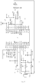
- FIG. 1 is a schematic diagram of a temperature measuring circuit according to some embodiments of the present disclosure.
- the temperature measuring circuit in some embodiments comprises: a control unit U1, which is used to implement the temperature collection and transmission control function of the temperature sensor.
- the control unit U1 may be implemented by using a logic chip having a sampling function, a current source output function, a reference output function, and a communication function, such as ADS1128, ADS1146, ADS1148, etc., but is not limited to the examples given above.
- the interfaces of the control unit U1 comprise, for example, a first current output interface IEXC1 (interface 20) and a second current output interface IEXC2 (interface 19).
- the interfaces of the control unit U1 also comprise several input/output interfaces (such as interfaces 11 ⁇ 18). In some embodiments, three interfaces with an analog-to-digital conversion function are selected as the first input/output interface AIN3 (interface 18), the second input/output interface AIN2 (interface 17) and third input/output interface AIN7 (interface 16). These interfaces are used to connect with the temperature sensor CN1 to achieve the temperature measurement of the temperature sensor CN1.
- AIN6, AIN5, AIN4, AIN1, AIN0 may be left unused or may be electrically connected to other temperature sensors to achieve temperature measurement of other temperature sensors.
- These input/output interfaces (such as interfaces 11 ⁇ 18) may work in parallel, and the collected temperature information may be transmitted to the temperature conversion unit T1 for temperature conversion, thereby alleviating the resource shortage of the analog-to-digital conversion interface of the temperature conversion unit T1.
- the interfaces of the control unit U1 also comprise a positive internal reference output interface VREFOUT (interface 9), a negative internal reference output interface VREFCOM (interface 10), a positive external reference input interface REFP0 (interface 5) and a negative external reference input interface REFN0 (interface 6), which may cooperate with other electronic components to provide a stable internal reference or external reference for the temperature measuring circuit.
- the interfaces of the control unit U1 also comprise communication interfaces (such as interfaces 23 ⁇ 28) for communicating with the temperature conversion unit T1.
- the output interface DOUT (interface 26) is connected to the SSP_MISO interface of the temperature conversion unit T1, and is used to output a differential signal sampling value between the first input/output interface AIN3 (interface 18) and the third input/output interface AIN7 (interface 16) to the temperature conversion unit T1, so that the temperature conversion unit T1 converts it into a temperature.
- the input interface DIN (interface 27) is connected to the SSP_MOSI interface of the temperature conversion unit T1, and is used by the temperature conversion unit T1 to input a configuration instruction to the control unit U1, so that the control unit U1 may output excitation currents of different levels.
- the communication interfaces also comprise, for example, a clock interface SCLK (interface 28), a data preparation output interface DRDY (interface 25), an enable interface CS (interface 24), a start control interface START (interface 23), and the like, which are connected to the SSP_CLK, ADS_DRDY, ADS_CS, ADS_START of the temperature conversion unit T1 respectively, and are used by the temperature conversion unit T1 to send corresponding control instructions to the control unit U1.
- the interfaces of the control unit U1 also comprise power interfaces, such as an analog power AVDD (interface 22), an analog ground AVSS (interface 21), a digital power DVDD (interface 1), and a digital ground DGND (interface 2).
- the interfaces of the control unit U1 also comprise a clock interface CLK (interface 3), a reset interface RESET (interface 4), and a positive external reference input interface REFP1 (interface 7) and a negative external reference input interface REFN1 (interface 8) that are left unused.
- the connection relationship between the control unit U1 and the temperature sensor CN1 is shown in FIG. 1 : the first current output interface IEXC1 (interface 20) and the first input/output interface AIN3 (interface 18) of the control unit U1 are electrically connected to the first interface CN1-1 of the temperature sensor CN1 respectively, the second current output interface IEXC2 (interface 19) and the second input/output interface AIN2 (interface 17) of the control unit U1 are electrically connected to the second interface CN1-2 of the temperature sensor CN1 respectively, and the third input/output interface AIN7 (interface 16) of the control unit U1 is electrically connected to the three interfaces CN1-3 of the temperature sensor CN1.
- a resistor R2 may also be disposed between the first input/output interface AIN3 (interface 18) of the control unit U1 and the first interface CN1-1 of the temperature sensor CN1, a resistor R1 may be disposed between the second input/output interface AIN2 (interface 17) of the control unit U1 and the second interface CN1-2 of the temperature sensor CN1, and a resistor R7 may be disposed between the third input/output interface AIN7 (interface 16) of the control unit U1 and the third interface CN1-3 of the temperature sensor CN1.
- the temperature sensor in three-wire connection requires two current sources provided by the first current output interface IEXC1 (interface 20) and the second current output interface IEXC2 (interface 19) respectively.
- the advantage of three-wire connection is that currents are applied to the wires of equal length of the first interface CN1-1 and the second interface CN1-2 of the temperature sensor CN1 respectively, which may eliminate the influence of the wire resistance.
- the temperature sensor in two-wire connection requires one current source, which is provided by the first current output interface IEXC1 (interface 20).
- the temperature measuring circuit can achieve hardware compatible for temperature sensors with two-wire and three-wire interfaces.
- a measuring method 200 of a temperature measuring circuit is shown in FIG. 2 , which particularly comprises the following steps.
- step S210 the first current output interface IEXC1 (interface 20) and the second current output interface IEXC2 (interface 19) of the control unit U1 are controlled to respectively output currents of the same level, for example, both are 1 mA.
- step S220 a differential signal between the second input/output interface AIN2 (interface 17) and the third input/output interface AIN7 (interface 16) of the control unit U1 is detected; if the differential signal is at a high level, step S230 is executed, and if the differential signal is at a low level, step S240 is executed.
- step S230 if the differential signal is at a high level, it is determined that the temperature sensor through which the current flows is a temperature sensor in a two-wire connection.
- step S240 if the differential signal is at a low level, it is determined that the temperature sensor through which the current flows is a temperature sensor in a three-wire connection.
- the temperature measuring circuit can achieve software compatible for temperature sensors with two-wire and three-wire interfaces.
- the temperature measuring circuit detects a differential signal, so that it has a strong anti-interference ability.
- the temperature measuring circuit may perform temperature measurement in the following manner.
- the first current output interface IEXC1 (interface 20) of the control unit U1 provides an excitation current for the temperature sensor in a two-wire connection; if the temperature sensor adopts a three-wire connection, the first current output interface IEXC1 (interface 20) of the control unit U1 provide two excitation currents that are identical to each other for the temperature sensor in a three-wire connection.
- the excitation current flows through the temperature sensor CN1, it passes through the first input/output interface AIN3 (interface 18) and the third input/output interface AIN7 (interface 16) of the control unit U1 to form a loop.
- the differential signal between the first input/output interface AIN3 (interface 18) and the third input/output interface AIN7 (interface 16) of the control unit U1 is sampled, and the differential signal sampled value is output to the temperature conversion unit T1.
- the temperature conversion unit T1 may, for example, convert the differential signal sampled value into a temperature according to a mapping table of temperature and voltage signals.
- the above temperature measurement process detects a differential signal, so that the temperature measuring circuit has a strong anti-interference ability.
- the current source output function of the temperature measuring circuit is realized by the first current output interface IEXC1 (interface 20) and the second current output interface IEXC2 (interface 19) of the control unit U1.
- the first current output interface IEXC1 (interface 20) and the second current output interface IEXC2 (interface 19) may be constant current source interfaces.
- the control unit U1 further comprises a constant current source and a configurable register.
- the first current output interface IEXC1 (interface 20) and the second current output interface IEXC2 (interface 19) of the control unit are electrically connected to the constant current source.
- the constant current source is electrically connected to the configurable register.
- the configurable register may output different control signals to the constant current source to excite the constant current source to output currents of different levels.
- the internal reference function of the temperature measuring circuit the positive internal reference output interface VREFOUT (interface 9) and the negative internal reference output interface VREFCOM (interface 10) in the control unit U1 are combined with a capacitor C6 in the temperature measuring circuit to serve the internal reference function, and provide a stable internal reference for the temperature measuring circuit.
- the negative internal reference output interface VREFCOM (interface 10) is grounded, and a capacitor C6 is disposed between the positive internal reference output interface VREFOUT (interface 9) and the negative internal reference output interface VREFCOM (interface 10).
- the temperature measuring circuit uses a stable internal reference as a reference, which is not easy to fluctuate due to the influence of the external environment, and is conducive to improving the detection accuracy.
- the positive external reference input interface REFP0 (interface 5) and the negative external reference input interface REFN0 (interface 6) in the control unit U1 are combined with the high-precision resistance network in the temperature measuring circuit to serve an external reference function, which provides an external reference for the temperature measuring circuit.
- the positive external reference input interface REFP0 (interface 5) is electrically connected to the third input/output interface AIN7 (interface 16).
- a resistance network is disposed on a connection line between the positive external reference input interface REFP0 (interface 5) and the negative external reference input interface REFN0 (interface 6).
- a resistance network with an accuracy higher than a preset value may be used, for example, the accuracy is 0.1%.
- the resistance network may be implemented, for example, by the parallel resistors R5 and R6 shown in FIG. 1 .
- the excitation current is 1000 ⁇ A
- the external reference voltage value V ref (1000 ⁇ R5 ⁇ R6) / (R5 + R6) .
- Filter function of the temperature measuring circuit it is realized by a filter circuit to suppress interference.
- the filter circuit may be logically divided into three parts: a power filter circuit for filtering the power supply, a sample input filter circuit for filtering a differential signal, and a reference filter circuit for filtering an external reference.
- the power filter circuit is shown as filter capacitors C4 and C7 in FIG. 1 , which respectively filter the analog power supply and digital power supply.
- the filter capacitor C4 is disposed on a circuit line between the analog power AVDD (interface 22) and the ground, and the filter capacitor C7 is disposed on a circuit line between the digital power DVDD (interface 1) and the ground.
- the sampling input filter circuit is shown as filter capacitors C1, C2, C3, C5, and C11 in FIG. 1 .
- the filter capacitors C3, C5, and C11 each are respectively electrically connected between the first input/output interface AIN3 (interface 18) and the ground, between the second input/output interface AIN2 (interface 17) and the ground, and between the third input/output interface AIN7 (interface 16) and ground.
- the filter capacitor C2 is electrically connected between the first input/output interface AIN3 (interface 18) and the second input/output interface AIN2 (interface 17).
- the filter capacitor C1 is electrically connected between the first input/output interface AIN3 (interface 18) and the third input/output interface AIN7 (interface 16).
- the reference filter circuit is a first filter circuit formed by R3 and C9 in FIG. 1 and a second filter circuit formed by R4 and C8.
- the capacitor C9 in the first filter circuit is disposed on a circuit line between the positive external reference input interface of the control unit and the ground, and the resistor R3 in the first filter circuit is disposed on a circuit line between the capacitor C9 and the resistance network (the parallel circuit of R5 and R6) in the first filter circuit.
- the capacitor C8 in the second filter circuit is disposed on a circuit line between the negative external reference input interface of the control unit and the ground.
- the resistor R4 in the second filter circuit is disposed on the circuit line between the capacitor C8 and the resistance network (the parallel circuit of R5 and R6) in the second filter circuit.
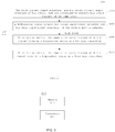
- FIG. 3 is a schematic diagram of a measuring apparatus for a temperature measuring circuit according to some embodiments of the present disclosure.
- a measuring apparatus 300 of a temperature measuring circuit in some embodiments comprises:
- processor 320 coupled to the memory 310, the processor 320 being configured to execute the measuring method of the temperature measuring circuit according to any one of the foregoing embodiments based on instructions stored in the memory 310.
- the memory 310 may comprise, for example, a system memory, a fixed non-volatile storage medium, and the like.
- the system memory stores, for example, an operating system, application programs, a boot loader, and other programs.
- FIG. 4 is a schematic diagram of a measuring apparatus for a temperature measuring circuit according to other embodiments of the present disclosure.
- the measuring apparatus 400 of a temperature measuring circuit in some embodiments comprises:
- control module 410 configured to control a first current output interface and a second current output interface of the control unit to respectively output currents of the same level
- a detection module 420 configured to detect a differential signal between a second input/output interface and a third input/output interface of the control unit
- a determining module 430 configured to determine that the temperature sensor through which the current flows is a temperature sensor in a two-wire connection if the differential signal is at a high level, and determine that the temperature sensor through which the current flows is a temperature sensor in a three-wire connection if the differential signal is at a low level.
- the measuring apparatus 400 of a temperature measuring circuit in some embodiments further comprises: a temperature conversion module 440, configured to perform temperature conversion based on an outputted differential signal sampling value between the first input/output interface and the third input/output interface of the control unit; the control module 410 is configured to control the first current output interface of the control unit to provide an excitation current to the temperature sensor in a two-wire connection, and control the first current output interface and the second current output interface of the control unit to provide two currents that are identical to each other to the temperature sensor in a three-wire connection.
- a temperature conversion module 440 configured to perform temperature conversion based on an outputted differential signal sampling value between the first input/output interface and the third input/output interface of the control unit
- the control module 410 is configured to control the first current output interface of the control unit to provide an excitation current to the temperature sensor in a two-wire connection, and control the first current output interface and the second current output interface of the control unit to provide two currents that are identical to each other to the temperature sensor in a
- the present disclosure also proposes a computer-readable storage medium storing computer programs, the computer programs being executed by a processor to implement the measuring method of a temperature measuring circuit according to any one of the foregoing embodiments.
- embodiments of the present disclosure may be provided as a method, a system, or a computer program product. Therefore, embodiments of the present disclosure can take the form of entirely hardware embodiments, entirely software embodiments or embodiments containing both hardware and software elements. Moreover, the present disclosure may take the form of a computer program product embodied on one or more computer-usable non-transitory storage media (comprising but not limited to disk storage, CD-ROM, optical memory, etc.) containing computer-usable program code therein.
Landscapes
- Physics & Mathematics (AREA)
- General Physics & Mathematics (AREA)
- Engineering & Computer Science (AREA)
- Power Engineering (AREA)
- Arrangements For Transmission Of Measured Signals (AREA)
Abstract
Description
- The present disclosure claims priority of Chinese patent application No.
201710940980.7, filed on October 11, 2017 - The present disclosure relates to the field of electronic circuits, and particularly relates to a temperature measuring circuit capable of being compatible with temperature sensors having two-wire and three-wire interfaces and a measuring method thereof.
- Compared with other temperature sensors, PT100 temperature sensors have the advantages of high accuracy, good stability and strong anti-interference ability in the temperature range of -50°C ∼ 600°C. The temperature measuring circuits of PT100 temperature sensors are mostly constant current source circuits or bridge circuits.
- The inventors found that, for PT100 temperature sensors in different wiring manners, such as in two-wire and three-wire connections, the temperature measuring circuits used by the hardware are different, and compatibility cannot be achieved between PT100 temperature sensors with two-wire and three-wire interfaces.
- One technical problem to be solved by the embodiments of the present disclosure is: the problem about the compatibility between temperature measuring circuits used for temperature sensors with two-wire and three-wire interfaces.
- According to an aspect of the present disclosure, a temperature measuring circuit is provided, comprising: a control unit comprising a first current output interface, a second current output interface, a first input/output interface, a second input/output interface, and a third input/output interface; wherein the first current output interface and the first input/output interface of the control unit are respectively electrically connected to a first interface of a temperature sensor; the second current output interface and the second input/output interface of the control unit are respectively electrically connected to a second interface of the temperature sensor; and the third input/output interface of the control unit is electrically connected to a third interface of the temperature sensor.
- In some embodiments of the present disclosure, the control unit further comprises an output interface for outputting a differential signal sampling value between the first input/output interface and the third input/output interface; the temperature measuring circuit further comprises a temperature conversion unit capable of converting an electrical signal sampling value into a temperature, the temperature conversion unit being electrically connected to the output interface of the control unit.
- In some embodiments of the present disclosure, the control unit further comprises a positive internal reference output interface and a negative internal reference output interface, the negative internal reference output interface being grounded; the temperature measuring circuit further comprises a capacitor connected in series between the positive internal reference output interface and negative internal reference output interface.
- In some embodiments of the present disclosure, the control unit further comprises a positive external reference input interface and a negative external reference input interface, the positive external reference input interface being electrically connected to the third current output interface; the temperature measuring circuit further comprises a resistance network with an accuracy higher than a preset value, the resistance network being disposed on a connection line between the external reference input interface and the negative external reference input interface.
- In some embodiments of the present disclosure, the first current output interface and the second current output interface of the control unit are constant current source interfaces.
- In some embodiments of the present disclosure, the control unit further comprises a constant current source and a configurable register; the first current output interface and the second current output interface of the control unit are respectively electrically connected to the constant current source, the constant current source being electrically connected to the configurable register, the configurable register outputting different control signals to the constant current source to excite the constant current source to output currents of different levels.
- In some embodiments of the present disclosure, the temperature measuring circuit further comprises filter capacitors each being electrically connected between the first input/output interface of the control unit and the ground, between the second input/output interface and the ground, and between the third input/output interface and the ground respectively, a filter capacitor being electrically connected between the first input/output interface and the second input/output interface, and a filter capacitor being electrically connected between the first input/output interface and the third input/output interface.
- In some embodiments of the present disclosure, the temperature measuring circuit further comprises a first filter circuit and a second filter circuit, each of the first filter circuit and the second filter circuit comprising resistors and capacitors; the capacitor in the first filter circuit is disposed on a circuit line between the positive external reference input interface of the control unit and a ground; the resistor in the first filter circuit is disposed on a circuit line between the capacitor in the first filter circuit and the resistance network; the capacitor in the second filter circuit is disposed on a circuit line between the negative external reference input interface of the control unit and the ground; the resistor in the second filter circuit is disposed on a circuit line between the capacitor in the second filter circuit and the resistance network.
- In some embodiments of the present disclosure, the control unit further comprises several other input/output interfaces than the first input/output interface, the second input/output interface, and the third input/output interface, the other input/output interfaces being electrically connected to other temperature sensors than the temperature sensor.
- In some embodiments of the present disclosure, the temperature sensor is a platinum thermal resistance temperature sensor.
- According to another aspect of the present disclosure, a measuring method of a temperature measuring circuit is provided, comprising: controlling a first current output interface and a second current output interface of a control unit to respectively output currents of the same level; detecting a differential signal between a second input/output interface and a third input/output interface of the control unit; if the differential signal is at a high level, determining that the temperature sensor through which the currents flows is a temperature sensor in a two-wire connection; if the differential signal is at a low level, determining that the temperature sensor through which the currents flows is a temperature sensor in a three-wire connection.
- In some embodiments of the present disclosure, the measuring method further comprising: controlling the first current output interface of the control unit to provide an excitation current for the temperature sensor in a two-wire connection; controlling the first current output interface and the second current output interface of the control unit to provide two currents that are identical to each other to the temperature sensor in a three-wire connection; and performing temperature conversion based on an outputted differential signal sampling value between the first input/output interface and the third input/output interface of the control unit.
- The present disclosure provides a temperature measuring circuit capable of being compatible with temperature sensors having two-wire and three-wire interfaces. In addition, through detecting the high and low voltages of the differential signal at the specified interfaces, it is determined whether the current temperature sensor is in a two-wire connection or a three-wire connection.
- The drawings needed to be used in the description of the embodiments or related art will be briefly introduced below. The present disclosure can be more clearly understood from the following detailed description with reference to the accompanying drawings.
- It is obvious that, the drawings illustrated as follows are merely some of the embodiments of the present disclosure. A person skilled in the art may also acquire other drawings according to the drawings on the premise that no inventive effort is involved.
-
FIG. 1 is a schematic diagram of a temperature measuring circuit according to some embodiments of the present disclosure; -
FIG. 2 is a schematic flowchart of a measuring method of a temperature measuring circuit of the present disclosure; -
FIG. 3 is a schematic diagram of a measuring apparatus of a temperature measuring circuit according to some embodiments of the present disclosure; -
FIG. 4 is a schematic diagram of a measuring apparatus of a temperature measuring circuit according to other embodiments of the present disclosure. - Below, a clear and complete description will be given for the technical solution of embodiments of the present disclosure with reference to the drawings of the embodiments.
- As mentioned above, some temperature sensors have different wiring methods. For example, platinum thermal resistance temperature sensors such as PT100, PT1000, etc. have two-wire and three-wire connections. These temperature sensors in different wiring connections use different temperature measuring circuits, resulting in a compatibility issue accordingly. Thus, the present disclosure provides a temperature measuring circuit capable of being compatible with temperature sensors having two-wire and three-wire interfaces.
- A temperature measuring circuit, as a logical division, comprises a current source output function, a temperature sensor sampling function, a reference function (comprising internal reference and external reference), a filtering function, a communication function, etc. The temperature measuring circuit and its various logic functions will be described in detail below with reference to
FIG. 1 . -
FIG. 1 is a schematic diagram of a temperature measuring circuit according to some embodiments of the present disclosure. - As shown in
FIG. 1 , the temperature measuring circuit in some embodiments comprises: a control unit U1, which is used to implement the temperature collection and transmission control function of the temperature sensor. The control unit U1 may be implemented by using a logic chip having a sampling function, a current source output function, a reference output function, and a communication function, such as ADS1128, ADS1146, ADS1148, etc., but is not limited to the examples given above. - The interfaces of the control unit U1, as shown in
FIG. 1 , comprise, for example, a first current output interface IEXC1 (interface 20) and a second current output interface IEXC2 (interface 19). The interfaces of the control unit U1 also comprise several input/output interfaces (such asinterfaces 11 ∼ 18). In some embodiments, three interfaces with an analog-to-digital conversion function are selected as the first input/output interface AIN3 (interface 18), the second input/output interface AIN2 (interface 17) and third input/output interface AIN7 (interface 16). These interfaces are used to connect with the temperature sensor CN1 to achieve the temperature measurement of the temperature sensor CN1. Other input/output interfaces AIN6, AIN5, AIN4, AIN1, AIN0 (interfaces 11 ∼ 15) may be left unused or may be electrically connected to other temperature sensors to achieve temperature measurement of other temperature sensors. These input/output interfaces (such asinterfaces 11 ∼ 18) may work in parallel, and the collected temperature information may be transmitted to the temperature conversion unit T1 for temperature conversion, thereby alleviating the resource shortage of the analog-to-digital conversion interface of the temperature conversion unit T1. The interfaces of the control unit U1 also comprise a positive internal reference output interface VREFOUT (interface 9), a negative internal reference output interface VREFCOM (interface 10), a positive external reference input interface REFP0 (interface 5) and a negative external reference input interface REFN0 (interface 6), which may cooperate with other electronic components to provide a stable internal reference or external reference for the temperature measuring circuit. The interfaces of the control unit U1 also comprise communication interfaces (such asinterfaces 23 ∼ 28) for communicating with the temperature conversion unit T1. The output interface DOUT (interface 26) is connected to the SSP_MISO interface of the temperature conversion unit T1, and is used to output a differential signal sampling value between the first input/output interface AIN3 (interface 18) and the third input/output interface AIN7 (interface 16) to the temperature conversion unit T1, so that the temperature conversion unit T1 converts it into a temperature. The input interface DIN (interface 27) is connected to the SSP_MOSI interface of the temperature conversion unit T1, and is used by the temperature conversion unit T1 to input a configuration instruction to the control unit U1, so that the control unit U1 may output excitation currents of different levels. The communication interfaces also comprise, for example, a clock interface SCLK (interface 28), a data preparation output interface DRDY (interface 25), an enable interface CS (interface 24), a start control interface START (interface 23), and the like, which are connected to the SSP_CLK, ADS_DRDY, ADS_CS, ADS_START of the temperature conversion unit T1 respectively, and are used by the temperature conversion unit T1 to send corresponding control instructions to the control unit U1. The interfaces of the control unit U1 also comprise power interfaces, such as an analog power AVDD (interface 22), an analog ground AVSS (interface 21), a digital power DVDD (interface 1), and a digital ground DGND (interface 2). The interfaces of the control unit U1 also comprise a clock interface CLK (interface 3), a reset interface RESET (interface 4), and a positive external reference input interface REFP1 (interface 7) and a negative external reference input interface REFN1 (interface 8) that are left unused. - The connection relationship between the control unit U1 and the temperature sensor CN1 is shown in
FIG. 1 : the first current output interface IEXC1 (interface 20) and the first input/output interface AIN3 (interface 18) of the control unit U1 are electrically connected to the first interface CN1-1 of the temperature sensor CN1 respectively, the second current output interface IEXC2 (interface 19) and the second input/output interface AIN2 (interface 17) of the control unit U1 are electrically connected to the second interface CN1-2 of the temperature sensor CN1 respectively, and the third input/output interface AIN7 (interface 16) of the control unit U1 is electrically connected to the three interfaces CN1-3 of the temperature sensor CN1. Optionally, in order to protect the circuit, a resistor R2 may also be disposed between the first input/output interface AIN3 (interface 18) of the control unit U1 and the first interface CN1-1 of the temperature sensor CN1, a resistor R1 may be disposed between the second input/output interface AIN2 (interface 17) of the control unit U1 and the second interface CN1-2 of the temperature sensor CN1, and a resistor R7 may be disposed between the third input/output interface AIN7 (interface 16) of the control unit U1 and the third interface CN1-3 of the temperature sensor CN1. - It can be seen that the temperature sensor in three-wire connection requires two current sources provided by the first current output interface IEXC1 (interface 20) and the second current output interface IEXC2 (interface 19) respectively. The advantage of three-wire connection is that currents are applied to the wires of equal length of the first interface CN1-1 and the second interface CN1-2 of the temperature sensor CN1 respectively, which may eliminate the influence of the wire resistance. The temperature sensor in two-wire connection requires one current source, which is provided by the first current output interface IEXC1 (interface 20). However, another current source provided by the second current output interface IEXC2 (interface 19) is extracted from the hardware, which is connected to the second interface CN1-2 of the temperature sensor CN1, and returns to the second input/output interface AIN2 (17 interface) of the control unit U1 through R1. Thus, the temperature measuring circuit can achieve hardware compatible for temperature sensors with two-wire and three-wire interfaces.
- On the basis of the foregoing hardware compatibility, it may be determined through logic judgment whether the temperature sensor CN1 adopts a two-wire connection or a three-wire connection. A
measuring method 200 of a temperature measuring circuit is shown inFIG. 2 , which particularly comprises the following steps. - In step S210, the first current output interface IEXC1 (interface 20) and the second current output interface IEXC2 (interface 19) of the control unit U1 are controlled to respectively output currents of the same level, for example, both are 1 mA.
- In step S220, a differential signal between the second input/output interface AIN2 (interface 17) and the third input/output interface AIN7 (interface 16) of the control unit U1 is detected; if the differential signal is at a high level, step S230 is executed, and if the differential signal is at a low level, step S240 is executed.
- In step S230, if the differential signal is at a high level, it is determined that the temperature sensor through which the current flows is a temperature sensor in a two-wire connection.
- In step S240, if the differential signal is at a low level, it is determined that the temperature sensor through which the current flows is a temperature sensor in a three-wire connection.
- Thus, the temperature measuring circuit can achieve software compatible for temperature sensors with two-wire and three-wire interfaces. The temperature measuring circuit detects a differential signal, so that it has a strong anti-interference ability.
- After it is determined that the temperature sensor adopts a two-wire connection or a three-wire connection, the temperature measuring circuit may perform temperature measurement in the following manner.
- First, if the temperature sensor adopts a two-wire connection, the first current output interface IEXC1 (interface 20) of the control unit U1 provides an excitation current for the temperature sensor in a two-wire connection; if the temperature sensor adopts a three-wire connection, the first current output interface IEXC1 (interface 20) of the control unit U1 provide two excitation currents that are identical to each other for the temperature sensor in a three-wire connection.
- Next, after the excitation current flows through the temperature sensor CN1, it passes through the first input/output interface AIN3 (interface 18) and the third input/output interface AIN7 (interface 16) of the control unit U1 to form a loop. The differential signal between the first input/output interface AIN3 (interface 18) and the third input/output interface AIN7 (interface 16) of the control unit U1 is sampled, and the differential signal sampled value is output to the temperature conversion unit T1.
- Finally, the temperature conversion unit T1 may, for example, convert the differential signal sampled value into a temperature according to a mapping table of temperature and voltage signals.
- The above temperature measurement process detects a differential signal, so that the temperature measuring circuit has a strong anti-interference ability.
- The current source output function of the temperature measuring circuit is realized by the first current output interface IEXC1 (interface 20) and the second current output interface IEXC2 (interface 19) of the control unit U1. In the control unit U1, the first current output interface IEXC1 (interface 20) and the second current output interface IEXC2 (interface 19) may be constant current source interfaces. Thus, the control unit U1 further comprises a constant current source and a configurable register. The first current output interface IEXC1 (interface 20) and the second current output interface IEXC2 (interface 19) of the control unit are electrically connected to the constant current source. The constant current source is electrically connected to the configurable register. The configurable register may output different control signals to the constant current source to excite the constant current source to output currents of different levels. The corresponding relationship between the configurable register output and the level of the constant current source is, for example, 000 = off, 001 = 50 µA, 110 = 1000 µA, and 111 = 1500 µA, but it is not limited to this example.
- Therefore, a stable excitation current is generated inside the control unit, so that the temperature measuring circuit is not easy to fluctuate due to the influence of the external environment, which is conducive to improving the detection accuracy.
- The internal reference function of the temperature measuring circuit: the positive internal reference output interface VREFOUT (interface 9) and the negative internal reference output interface VREFCOM (interface 10) in the control unit U1 are combined with a capacitor C6 in the temperature measuring circuit to serve the internal reference function, and provide a stable internal reference for the temperature measuring circuit. As shown in
FIG. 1 , the negative internal reference output interface VREFCOM (interface 10) is grounded, and a capacitor C6 is disposed between the positive internal reference output interface VREFOUT (interface 9) and the negative internal reference output interface VREFCOM (interface 10). - Therefore, the temperature measuring circuit uses a stable internal reference as a reference, which is not easy to fluctuate due to the influence of the external environment, and is conducive to improving the detection accuracy.
- External reference function of the temperature measuring circuit: the positive external reference input interface REFP0 (interface 5) and the negative external reference input interface REFN0 (interface 6) in the control unit U1 are combined with the high-precision resistance network in the temperature measuring circuit to serve an external reference function, which provides an external reference for the temperature measuring circuit. As shown in
FIG. 1 , the positive external reference input interface REFP0 (interface 5) is electrically connected to the third input/output interface AIN7 (interface 16). A resistance network is disposed on a connection line between the positive external reference input interface REFP0 (interface 5) and the negative external reference input interface REFN0 (interface 6). A resistance network with an accuracy higher than a preset value may be used, for example, the accuracy is 0.1%. The resistance network may be implemented, for example, by the parallel resistors R5 and R6 shown inFIG. 1 . When the excitation current is 1000 µA, the external reference voltage value Vref = (1000 × R5 × R6) / (R5 + R6) . - Filter function of the temperature measuring circuit: it is realized by a filter circuit to suppress interference. The filter circuit may be logically divided into three parts: a power filter circuit for filtering the power supply, a sample input filter circuit for filtering a differential signal, and a reference filter circuit for filtering an external reference.
- The power filter circuit is shown as filter capacitors C4 and C7 in
FIG. 1 , which respectively filter the analog power supply and digital power supply. The filter capacitor C4 is disposed on a circuit line between the analog power AVDD (interface 22) and the ground, and the filter capacitor C7 is disposed on a circuit line between the digital power DVDD (interface 1) and the ground. - The sampling input filter circuit is shown as filter capacitors C1, C2, C3, C5, and C11 in
FIG. 1 . The filter capacitors C3, C5, and C11 each are respectively electrically connected between the first input/output interface AIN3 (interface 18) and the ground, between the second input/output interface AIN2 (interface 17) and the ground, and between the third input/output interface AIN7 (interface 16) and ground. The filter capacitor C2 is electrically connected between the first input/output interface AIN3 (interface 18) and the second input/output interface AIN2 (interface 17). The filter capacitor C1 is electrically connected between the first input/output interface AIN3 (interface 18) and the third input/output interface AIN7 (interface 16). - The reference filter circuit is a first filter circuit formed by R3 and C9 in
FIG. 1 and a second filter circuit formed by R4 and C8. The capacitor C9 in the first filter circuit is disposed on a circuit line between the positive external reference input interface of the control unit and the ground, and the resistor R3 in the first filter circuit is disposed on a circuit line between the capacitor C9 and the resistance network (the parallel circuit of R5 and R6) in the first filter circuit. The capacitor C8 in the second filter circuit is disposed on a circuit line between the negative external reference input interface of the control unit and the ground. The resistor R4 in the second filter circuit is disposed on the circuit line between the capacitor C8 and the resistance network (the parallel circuit of R5 and R6) in the second filter circuit. -
FIG. 3 is a schematic diagram of a measuring apparatus for a temperature measuring circuit according to some embodiments of the present disclosure. - As shown in
FIG. 3 , a measuringapparatus 300 of a temperature measuring circuit in some embodiments comprises: - a
memory 310; and - a
processor 320 coupled to thememory 310, theprocessor 320 being configured to execute the measuring method of the temperature measuring circuit according to any one of the foregoing embodiments based on instructions stored in thememory 310. - In some embodiments, the
memory 310 may comprise, for example, a system memory, a fixed non-volatile storage medium, and the like. The system memory stores, for example, an operating system, application programs, a boot loader, and other programs. -
FIG. 4 is a schematic diagram of a measuring apparatus for a temperature measuring circuit according to other embodiments of the present disclosure. - As shown in
FIG. 4 , the measuringapparatus 400 of a temperature measuring circuit in some embodiments comprises: - a
control module 410, configured to control a first current output interface and a second current output interface of the control unit to respectively output currents of the same level; - a
detection module 420, configured to detect a differential signal between a second input/output interface and a third input/output interface of the control unit; - a determining
module 430, configured to determine that the temperature sensor through which the current flows is a temperature sensor in a two-wire connection if the differential signal is at a high level, and determine that the temperature sensor through which the current flows is a temperature sensor in a three-wire connection if the differential signal is at a low level. - As shown in
FIG. 4 , the measuringapparatus 400 of a temperature measuring circuit in some embodiments further comprises: atemperature conversion module 440, configured to perform temperature conversion based on an outputted differential signal sampling value between the first input/output interface and the third input/output interface of the control unit; thecontrol module 410 is configured to control the first current output interface of the control unit to provide an excitation current to the temperature sensor in a two-wire connection, and control the first current output interface and the second current output interface of the control unit to provide two currents that are identical to each other to the temperature sensor in a three-wire connection. - The present disclosure also proposes a computer-readable storage medium storing computer programs, the computer programs being executed by a processor to implement the measuring method of a temperature measuring circuit according to any one of the foregoing embodiments.
- Those skilled in the art should understand that the embodiments of the present disclosure may be provided as a method, a system, or a computer program product. Therefore, embodiments of the present disclosure can take the form of entirely hardware embodiments, entirely software embodiments or embodiments containing both hardware and software elements. Moreover, the present disclosure may take the form of a computer program product embodied on one or more computer-usable non-transitory storage media (comprising but not limited to disk storage, CD-ROM, optical memory, etc.) containing computer-usable program code therein.
- The above is merely some embodiments of this disclosure, and is not limitation to this disclosure. Within spirit and principles of this disclosure, any modification, replacement, improvement and etc. shall be contained in the protection scope of this disclosure.
Claims (16)
- A temperature measuring circuit, comprising:a control unit, comprising a first current output interface, a second current output interface, a first input/output interface, a second input/output interface, and a third input/output interface;wherein the first current output interface and the first input/output interface of the control unit are respectively electrically connected to a first interface of a temperature sensor; the second current output interface and the second input/output interface of the control unit are respectively electrically connected to a second interface of the temperature sensor; and the third input/output interface of the control unit is electrically connected to a third interface of the temperature sensor.
- The temperature measuring circuit according to claim 1, wherein
the control unit further comprises an output interface for outputting a differential signal sampling value between the first input/output interface and the third input/output interface;
the temperature measuring circuit further comprises a temperature conversion unit capable of converting an electrical signal sampling value into a temperature, the temperature conversion unit being electrically connected to the output interface of the control unit. - The temperature measuring circuit according to claim 1, wherein
the control unit further comprises a positive internal reference output interface and a negative internal reference output interface, the negative internal reference output interface being grounded;
the temperature measuring circuit further comprises a capacitor connected in series between the positive internal reference output interface and negative internal reference output interface. - The temperature measuring circuit according to claim 1, wherein
the control unit further comprises a positive external reference input interface and a negative external reference input interface, the positive external reference input interface being electrically connected to the third current output interface;
the temperature measuring circuit further comprises a resistance network with an accuracy higher than a preset value, the resistance network being disposed on a connection line between the external reference input interface and the negative external reference input interface. - The temperature measuring circuit according to claim 1, wherein
the first current output interface and the second current output interface of the control unit are constant current source interfaces. - The temperature measuring circuit according to claim 5, wherein
the control unit further comprises a constant current source and a configurable register;
the first current output interface and the second current output interface of the control unit are respectively electrically connected to the constant current source, the constant current source being electrically connected to the configurable register, the configurable register outputting different control signals to the constant current source to excite the constant current source to output currents of different levels. - The temperature measuring circuit according to claim 1, wherein
the temperature measuring circuit further comprises filter capacitors, filter capacitors each being electrically connected between the first input/output interface of the control unit and the ground, between the second input/output interface and the ground, and between the third input/output interface and the ground respectively, a filter capacitor being electrically connected between the first input/output interface and the second input/output interface, and a filter capacitor being electrically connected between the first input/output interface and the third input/output interface. - The temperature measuring circuit according to claim 4, wherein
the temperature measuring circuit further comprises a first filter circuit and a second filter circuit, each of the first filter circuit and the second filter circuit comprising resistors and capacitors;
the capacitor in the first filter circuit is disposed on a circuit line between the positive external reference input interface of the control unit and a ground; the resistor in the first filter circuit is disposed on a circuit line between the capacitor in the first filter circuit and the resistance network;
the capacitor in the second filter circuit is disposed on a circuit line between the negative external reference input interface of the control unit and the ground; the resistor in the second filter circuit is disposed on a circuit line between the capacitor in the second filter circuit and the resistance network. - The temperature measuring circuit according to claim 1, wherein
the control unit further comprises several other input/output interfaces than the first input/output interface, the second input/output interface, and the third input/output interface, the other input/output interfaces being electrically connected to other temperature sensors than the temperature sensor. - The temperature measuring circuit according to any one of claims 1 to 9, wherein
the temperature sensor is a platinum thermal resistance temperature sensor. - A measuring method of a temperature measuring circuit, comprising:controlling a first current output interface and a second current output interface of a control unit to respectively output currents of the same level;detecting a differential signal between a second input/output interface and a third input/output interface of the control unit;if the differential signal is at a high level, determining that the temperature sensor through which the currents flows is a temperature sensor in a two-wire connection;if the differential signal is at a low level, determining that the temperature sensor through which the currents flows is a temperature sensor in a three-wire connection.
- The measuring method according to claim 11, further comprising:controlling the first current output interface of the control unit to provide an excitation current for the temperature sensor in a two-wire connection;controlling the first current output interface and the second current output interface of the control unit to provide two currents that are identical to each other to the temperature sensor in a three-wire connection; andperforming temperature conversion based on an outputted differential signal sampling value between the first input/output interface and the third input/output interface of the control unit.
- A measuring apparatus of a temperature measuring circuit, comprising:memory; anda processor coupled to the memory, the processor configured to carry out the measuring method of a temperature measuring circuit according to claim 11 or 12 based on instructions stored in the memory.
- A measuring apparatus of a temperature measuring circuit, comprising:a control module, configured to control a first current output interface and a second current output interface of the control unit to respectively output currents of the same level;a detection module, configured to detect a differential signal between a second input/output interface and a third input/output interface of the control unit;a determining module, configured to determine that the temperature sensor through which the current flows is a temperature sensor in a two-wire connection if the differential signal is at a high level, and determine that the temperature sensor through which the current flows is a temperature sensor in a three-wire connection if the differential signal is at a low level.
- The measuring apparatus according to claim 14, further comprising:a temperature conversion module, configured to perform temperature conversion based on an outputted differential signal sampling value between the first input/output interface and the third input/output interface of the control unit;wherein the control module is configured to control the first current output interface of the control unit to provide an excitation current to the temperature sensor in a two-wire connection, and control the first current output interface and the second current output interface of the control unit to provide two currents that are identical to each other to the temperature sensor in a three-wire connection.
- A computer-readable storage medium storing computer programs, the computer programs being executed by a processor to implement the measuring method of a temperature measuring circuit according to claim 11 or 12.
Applications Claiming Priority (2)
| Application Number | Priority Date | Filing Date | Title |
|---|---|---|---|
| CN201710940980.7A CN107655586B (en) | 2017-10-11 | 2017-10-11 | Temperature measuring circuit and detection method thereof |
| PCT/CN2017/118938 WO2019071844A1 (en) | 2017-10-11 | 2017-12-27 | Temperature measuring circuit and measuring method thereof |
Publications (3)
| Publication Number | Publication Date |
|---|---|
| EP3647749A1 true EP3647749A1 (en) | 2020-05-06 |
| EP3647749A4 EP3647749A4 (en) | 2020-10-21 |
| EP3647749B1 EP3647749B1 (en) | 2023-11-22 |
Family
ID=61117842
Family Applications (1)
| Application Number | Title | Priority Date | Filing Date |
|---|---|---|---|
| EP17928269.4A Active EP3647749B1 (en) | 2017-10-11 | 2017-12-27 | Temperature measuring circuit and measuring method thereof |
Country Status (4)
| Country | Link |
|---|---|
| US (1) | US11604101B2 (en) |
| EP (1) | EP3647749B1 (en) |
| CN (1) | CN107655586B (en) |
| WO (1) | WO2019071844A1 (en) |
Family Cites Families (15)
| Publication number | Priority date | Publication date | Assignee | Title |
|---|---|---|---|---|
| US4623266A (en) * | 1985-09-24 | 1986-11-18 | Rosemount Inc. | Cold junction compensation for thermocouple |
| JP3715752B2 (en) * | 1997-07-23 | 2005-11-16 | 株式会社チノー | Resistance thermometer |
| DE10258366A1 (en) * | 2002-12-12 | 2004-07-08 | Endress + Hauser Wetzer Gmbh + Co Kg | Method and device for measuring the resistance of a temperature-dependent resistance element |
| DE10359988A1 (en) * | 2003-12-19 | 2005-07-14 | Siemens Ag | Measuring device, in particular temperature transmitter |
| CN101806640B (en) | 2010-04-20 | 2011-11-30 | 杭州和利时自动化有限公司 | Measurement system of thermal resistance signal |
| TW201143513A (en) * | 2010-05-24 | 2011-12-01 | Delta Electronics Inc | Light source module |
| CN102012279A (en) * | 2010-10-19 | 2011-04-13 | 上海微程电气设备有限公司 | Dual-constant current source temperature measurement system for thermal resistor |
| US9228876B2 (en) | 2011-09-13 | 2016-01-05 | Zodiac Aerotechnics | Liquid sensor using temperature compensation |
| KR101338756B1 (en) | 2012-03-15 | 2013-12-06 | 엘에스산전 주식회사 | Apparatus for Temperature Detection Using Resistance Temperature Detector |
| CN202928712U (en) | 2012-07-30 | 2013-05-08 | 北京维盛新仪科技有限公司 | Fully-functional temperature transmitter |
| US9228905B2 (en) * | 2012-08-21 | 2016-01-05 | General Electric Company | RTD measurement device |
| CN102879124A (en) * | 2012-10-10 | 2013-01-16 | 成都阜特科技股份有限公司 | Temperature acquisition module |
| JP6092129B2 (en) * | 2014-01-16 | 2017-03-08 | アズビル株式会社 | Temperature measuring system and temperature measuring instrument |
| CN204694370U (en) | 2015-04-20 | 2015-10-07 | 山东创恒科技发展有限公司 | Based on the multichannel three-wire system resistance and temperature detection system of two constant current source |
| CN207231660U (en) * | 2017-10-11 | 2018-04-13 | 珠海格力电器股份有限公司 | Temperature measuring circuit |
-
2017
- 2017-10-11 CN CN201710940980.7A patent/CN107655586B/en active Active
- 2017-12-27 US US16/652,332 patent/US11604101B2/en active Active
- 2017-12-27 EP EP17928269.4A patent/EP3647749B1/en active Active
- 2017-12-27 WO PCT/CN2017/118938 patent/WO2019071844A1/en not_active Ceased
Also Published As
| Publication number | Publication date |
|---|---|
| US11604101B2 (en) | 2023-03-14 |
| CN107655586B (en) | 2024-03-29 |
| CN107655586A (en) | 2018-02-02 |
| WO2019071844A1 (en) | 2019-04-18 |
| EP3647749A4 (en) | 2020-10-21 |
| EP3647749B1 (en) | 2023-11-22 |
| US20200355561A1 (en) | 2020-11-12 |
Similar Documents
| Publication | Publication Date | Title |
|---|---|---|
| US9524056B2 (en) | Capacitive voltage information sensing circuit and related anti-noise touch circuit | |
| US20110242048A1 (en) | Capacitive sensing analog front end | |
| CN203705533U (en) | Current detection circuit of Hall current sensor of electric automobile | |
| CN215296515U (en) | Pressure detection system | |
| CN105242752A (en) | Backplate and hardware address taking method for same | |
| CN106802372B (en) | A method for detecting the change of capacitance value | |
| WO2019023923A1 (en) | Method for determining touch position and touch control chip | |
| CN107181300A (en) | Charge protector, the method and apparatus for calibrating charging equipment | |
| CN107861053A (en) | A kind of the detection circuit and electric quantity metering chip of the circuit parameter for detecting bleeder circuit | |
| KR102632360B1 (en) | Dual slope analog to digital converter with parallel counting structure | |
| CN207816478U (en) | Temperature measuring circuit | |
| CN104390718A (en) | Temperature detection method | |
| CN104697604B (en) | It is a kind of can field calibration capacitance level transducer | |
| US11604101B2 (en) | Temperature measuring circuit and measuring method thereof | |
| CN108254096B (en) | Temperature measuring circuit, detecting device and detecting method thereof and computer readable storage medium | |
| CN207231660U (en) | Temperature measuring circuit | |
| CN106443137B (en) | A current collector for two-wire sensors | |
| CN103049154A (en) | Touch signal acquisition method for capacitive touch switch | |
| CN218938812U (en) | Signal acquisition circuit, signal acquisition equipment and vehicle | |
| CN115219781A (en) | Positive and negative voltage sampling circuit and sampling system with the same | |
| CN116054826A (en) | Digital low-cost high-precision current frequency conversion system | |
| CN204376876U (en) | Data acquisition system | |
| CN112805665A (en) | Capacitive sensing system, sensing circuit of capacitive touch screen and sensing method | |
| CN220872636U (en) | Short-circuit port detection circuit with IO port replaced by ADC port and electric energy meter | |
| CN217505012U (en) | Direct current rifle temperature isolation detection circuitry that charges |
Legal Events
| Date | Code | Title | Description |
|---|---|---|---|
| STAA | Information on the status of an ep patent application or granted ep patent |
Free format text: STATUS: THE INTERNATIONAL PUBLICATION HAS BEEN MADE |
|
| PUAI | Public reference made under article 153(3) epc to a published international application that has entered the european phase |
Free format text: ORIGINAL CODE: 0009012 |
|
| STAA | Information on the status of an ep patent application or granted ep patent |
Free format text: STATUS: REQUEST FOR EXAMINATION WAS MADE |
|
| 17P | Request for examination filed |
Effective date: 20200131 |
|
| AK | Designated contracting states |
Kind code of ref document: A1 Designated state(s): AL AT BE BG CH CY CZ DE DK EE ES FI FR GB GR HR HU IE IS IT LI LT LU LV MC MK MT NL NO PL PT RO RS SE SI SK SM TR |
|
| AX | Request for extension of the european patent |
Extension state: BA ME |
|
| A4 | Supplementary search report drawn up and despatched |
Effective date: 20200917 |
|
| RIC1 | Information provided on ipc code assigned before grant |
Ipc: G01K 7/20 20060101AFI20200911BHEP |
|
| DAV | Request for validation of the european patent (deleted) | ||
| DAX | Request for extension of the european patent (deleted) | ||
| STAA | Information on the status of an ep patent application or granted ep patent |
Free format text: STATUS: EXAMINATION IS IN PROGRESS |
|
| 17Q | First examination report despatched |
Effective date: 20221006 |
|
| GRAP | Despatch of communication of intention to grant a patent |
Free format text: ORIGINAL CODE: EPIDOSNIGR1 |
|
| STAA | Information on the status of an ep patent application or granted ep patent |
Free format text: STATUS: GRANT OF PATENT IS INTENDED |
|
| P01 | Opt-out of the competence of the unified patent court (upc) registered |
Effective date: 20230530 |
|
| INTG | Intention to grant announced |
Effective date: 20230707 |
|
| GRAS | Grant fee paid |
Free format text: ORIGINAL CODE: EPIDOSNIGR3 |
|
| GRAA | (expected) grant |
Free format text: ORIGINAL CODE: 0009210 |
|
| STAA | Information on the status of an ep patent application or granted ep patent |
Free format text: STATUS: THE PATENT HAS BEEN GRANTED |
|
| AK | Designated contracting states |
Kind code of ref document: B1 Designated state(s): AL AT BE BG CH CY CZ DE DK EE ES FI FR GB GR HR HU IE IS IT LI LT LU LV MC MK MT NL NO PL PT RO RS SE SI SK SM TR |
|
| REG | Reference to a national code |
Ref country code: GB Ref legal event code: FG4D |
|
| REG | Reference to a national code |
Ref country code: CH Ref legal event code: EP |
|
| REG | Reference to a national code |
Ref country code: DE Ref legal event code: R096 Ref document number: 602017076881 Country of ref document: DE |
|
| REG | Reference to a national code |
Ref country code: IE Ref legal event code: FG4D |
|
| REG | Reference to a national code |
Ref country code: NL Ref legal event code: FP |
|
| REG | Reference to a national code |
Ref country code: LT Ref legal event code: MG9D |
|
| PG25 | Lapsed in a contracting state [announced via postgrant information from national office to epo] |
Ref country code: GR Free format text: LAPSE BECAUSE OF FAILURE TO SUBMIT A TRANSLATION OF THE DESCRIPTION OR TO PAY THE FEE WITHIN THE PRESCRIBED TIME-LIMIT Effective date: 20240223 |
|
| PG25 | Lapsed in a contracting state [announced via postgrant information from national office to epo] |
Ref country code: IS Free format text: LAPSE BECAUSE OF FAILURE TO SUBMIT A TRANSLATION OF THE DESCRIPTION OR TO PAY THE FEE WITHIN THE PRESCRIBED TIME-LIMIT Effective date: 20240322 |
|
| PG25 | Lapsed in a contracting state [announced via postgrant information from national office to epo] |
Ref country code: LT Free format text: LAPSE BECAUSE OF FAILURE TO SUBMIT A TRANSLATION OF THE DESCRIPTION OR TO PAY THE FEE WITHIN THE PRESCRIBED TIME-LIMIT Effective date: 20231122 |
|
| REG | Reference to a national code |
Ref country code: AT Ref legal event code: MK05 Ref document number: 1634259 Country of ref document: AT Kind code of ref document: T Effective date: 20231122 |
|
| PG25 | Lapsed in a contracting state [announced via postgrant information from national office to epo] |
Ref country code: AT Free format text: LAPSE BECAUSE OF FAILURE TO SUBMIT A TRANSLATION OF THE DESCRIPTION OR TO PAY THE FEE WITHIN THE PRESCRIBED TIME-LIMIT Effective date: 20231122 |
|
| PG25 | Lapsed in a contracting state [announced via postgrant information from national office to epo] |
Ref country code: ES Free format text: LAPSE BECAUSE OF FAILURE TO SUBMIT A TRANSLATION OF THE DESCRIPTION OR TO PAY THE FEE WITHIN THE PRESCRIBED TIME-LIMIT Effective date: 20231122 |
|
| PG25 | Lapsed in a contracting state [announced via postgrant information from national office to epo] |
Ref country code: LT Free format text: LAPSE BECAUSE OF FAILURE TO SUBMIT A TRANSLATION OF THE DESCRIPTION OR TO PAY THE FEE WITHIN THE PRESCRIBED TIME-LIMIT Effective date: 20231122 Ref country code: IS Free format text: LAPSE BECAUSE OF FAILURE TO SUBMIT A TRANSLATION OF THE DESCRIPTION OR TO PAY THE FEE WITHIN THE PRESCRIBED TIME-LIMIT Effective date: 20240322 Ref country code: GR Free format text: LAPSE BECAUSE OF FAILURE TO SUBMIT A TRANSLATION OF THE DESCRIPTION OR TO PAY THE FEE WITHIN THE PRESCRIBED TIME-LIMIT Effective date: 20240223 Ref country code: ES Free format text: LAPSE BECAUSE OF FAILURE TO SUBMIT A TRANSLATION OF THE DESCRIPTION OR TO PAY THE FEE WITHIN THE PRESCRIBED TIME-LIMIT Effective date: 20231122 Ref country code: BG Free format text: LAPSE BECAUSE OF FAILURE TO SUBMIT A TRANSLATION OF THE DESCRIPTION OR TO PAY THE FEE WITHIN THE PRESCRIBED TIME-LIMIT Effective date: 20240222 Ref country code: AT Free format text: LAPSE BECAUSE OF FAILURE TO SUBMIT A TRANSLATION OF THE DESCRIPTION OR TO PAY THE FEE WITHIN THE PRESCRIBED TIME-LIMIT Effective date: 20231122 Ref country code: PT Free format text: LAPSE BECAUSE OF FAILURE TO SUBMIT A TRANSLATION OF THE DESCRIPTION OR TO PAY THE FEE WITHIN THE PRESCRIBED TIME-LIMIT Effective date: 20240322 |
|
| PG25 | Lapsed in a contracting state [announced via postgrant information from national office to epo] |
Ref country code: SE Free format text: LAPSE BECAUSE OF FAILURE TO SUBMIT A TRANSLATION OF THE DESCRIPTION OR TO PAY THE FEE WITHIN THE PRESCRIBED TIME-LIMIT Effective date: 20231122 Ref country code: RS Free format text: LAPSE BECAUSE OF FAILURE TO SUBMIT A TRANSLATION OF THE DESCRIPTION OR TO PAY THE FEE WITHIN THE PRESCRIBED TIME-LIMIT Effective date: 20231122 Ref country code: PL Free format text: LAPSE BECAUSE OF FAILURE TO SUBMIT A TRANSLATION OF THE DESCRIPTION OR TO PAY THE FEE WITHIN THE PRESCRIBED TIME-LIMIT Effective date: 20231122 Ref country code: NO Free format text: LAPSE BECAUSE OF FAILURE TO SUBMIT A TRANSLATION OF THE DESCRIPTION OR TO PAY THE FEE WITHIN THE PRESCRIBED TIME-LIMIT Effective date: 20240222 Ref country code: LV Free format text: LAPSE BECAUSE OF FAILURE TO SUBMIT A TRANSLATION OF THE DESCRIPTION OR TO PAY THE FEE WITHIN THE PRESCRIBED TIME-LIMIT Effective date: 20231122 Ref country code: HR Free format text: LAPSE BECAUSE OF FAILURE TO SUBMIT A TRANSLATION OF THE DESCRIPTION OR TO PAY THE FEE WITHIN THE PRESCRIBED TIME-LIMIT Effective date: 20231122 |
|
| PG25 | Lapsed in a contracting state [announced via postgrant information from national office to epo] |
Ref country code: DK Free format text: LAPSE BECAUSE OF FAILURE TO SUBMIT A TRANSLATION OF THE DESCRIPTION OR TO PAY THE FEE WITHIN THE PRESCRIBED TIME-LIMIT Effective date: 20231122 |
|
| PG25 | Lapsed in a contracting state [announced via postgrant information from national office to epo] |
Ref country code: CZ Free format text: LAPSE BECAUSE OF FAILURE TO SUBMIT A TRANSLATION OF THE DESCRIPTION OR TO PAY THE FEE WITHIN THE PRESCRIBED TIME-LIMIT Effective date: 20231122 |
|
| PG25 | Lapsed in a contracting state [announced via postgrant information from national office to epo] |
Ref country code: SK Free format text: LAPSE BECAUSE OF FAILURE TO SUBMIT A TRANSLATION OF THE DESCRIPTION OR TO PAY THE FEE WITHIN THE PRESCRIBED TIME-LIMIT Effective date: 20231122 |
|
| PG25 | Lapsed in a contracting state [announced via postgrant information from national office to epo] |
Ref country code: SM Free format text: LAPSE BECAUSE OF FAILURE TO SUBMIT A TRANSLATION OF THE DESCRIPTION OR TO PAY THE FEE WITHIN THE PRESCRIBED TIME-LIMIT Effective date: 20231122 Ref country code: SK Free format text: LAPSE BECAUSE OF FAILURE TO SUBMIT A TRANSLATION OF THE DESCRIPTION OR TO PAY THE FEE WITHIN THE PRESCRIBED TIME-LIMIT Effective date: 20231122 Ref country code: RO Free format text: LAPSE BECAUSE OF FAILURE TO SUBMIT A TRANSLATION OF THE DESCRIPTION OR TO PAY THE FEE WITHIN THE PRESCRIBED TIME-LIMIT Effective date: 20231122 Ref country code: EE Free format text: LAPSE BECAUSE OF FAILURE TO SUBMIT A TRANSLATION OF THE DESCRIPTION OR TO PAY THE FEE WITHIN THE PRESCRIBED TIME-LIMIT Effective date: 20231122 Ref country code: DK Free format text: LAPSE BECAUSE OF FAILURE TO SUBMIT A TRANSLATION OF THE DESCRIPTION OR TO PAY THE FEE WITHIN THE PRESCRIBED TIME-LIMIT Effective date: 20231122 Ref country code: CZ Free format text: LAPSE BECAUSE OF FAILURE TO SUBMIT A TRANSLATION OF THE DESCRIPTION OR TO PAY THE FEE WITHIN THE PRESCRIBED TIME-LIMIT Effective date: 20231122 |
|
| REG | Reference to a national code |
Ref country code: CH Ref legal event code: PL |
|
| PG25 | Lapsed in a contracting state [announced via postgrant information from national office to epo] |
Ref country code: LU Free format text: LAPSE BECAUSE OF NON-PAYMENT OF DUE FEES Effective date: 20231227 |
|
| REG | Reference to a national code |
Ref country code: DE Ref legal event code: R097 Ref document number: 602017076881 Country of ref document: DE |
|
| PG25 | Lapsed in a contracting state [announced via postgrant information from national office to epo] |
Ref country code: MC Free format text: LAPSE BECAUSE OF FAILURE TO SUBMIT A TRANSLATION OF THE DESCRIPTION OR TO PAY THE FEE WITHIN THE PRESCRIBED TIME-LIMIT Effective date: 20231122 |
|
| REG | Reference to a national code |
Ref country code: BE Ref legal event code: MM Effective date: 20231231 |
|
| PG25 | Lapsed in a contracting state [announced via postgrant information from national office to epo] |
Ref country code: MC Free format text: LAPSE BECAUSE OF FAILURE TO SUBMIT A TRANSLATION OF THE DESCRIPTION OR TO PAY THE FEE WITHIN THE PRESCRIBED TIME-LIMIT Effective date: 20231122 Ref country code: LU Free format text: LAPSE BECAUSE OF NON-PAYMENT OF DUE FEES Effective date: 20231227 |
|
| PLBE | No opposition filed within time limit |
Free format text: ORIGINAL CODE: 0009261 |
|
| STAA | Information on the status of an ep patent application or granted ep patent |
Free format text: STATUS: NO OPPOSITION FILED WITHIN TIME LIMIT |
|
| REG | Reference to a national code |
Ref country code: IE Ref legal event code: MM4A |
|
| PG25 | Lapsed in a contracting state [announced via postgrant information from national office to epo] |
Ref country code: IE Free format text: LAPSE BECAUSE OF NON-PAYMENT OF DUE FEES Effective date: 20231227 |
|
| PG25 | Lapsed in a contracting state [announced via postgrant information from national office to epo] |
Ref country code: BE Free format text: LAPSE BECAUSE OF NON-PAYMENT OF DUE FEES Effective date: 20231231 |
|
| PG25 | Lapsed in a contracting state [announced via postgrant information from national office to epo] |
Ref country code: CH Free format text: LAPSE BECAUSE OF NON-PAYMENT OF DUE FEES Effective date: 20231231 |
|
| PG25 | Lapsed in a contracting state [announced via postgrant information from national office to epo] |
Ref country code: SI Free format text: LAPSE BECAUSE OF FAILURE TO SUBMIT A TRANSLATION OF THE DESCRIPTION OR TO PAY THE FEE WITHIN THE PRESCRIBED TIME-LIMIT Effective date: 20231122 |
|
| 26N | No opposition filed |
Effective date: 20240823 |
|
| PG25 | Lapsed in a contracting state [announced via postgrant information from national office to epo] |
Ref country code: SI Free format text: LAPSE BECAUSE OF FAILURE TO SUBMIT A TRANSLATION OF THE DESCRIPTION OR TO PAY THE FEE WITHIN THE PRESCRIBED TIME-LIMIT Effective date: 20231122 Ref country code: IE Free format text: LAPSE BECAUSE OF NON-PAYMENT OF DUE FEES Effective date: 20231227 Ref country code: CH Free format text: LAPSE BECAUSE OF NON-PAYMENT OF DUE FEES Effective date: 20231231 Ref country code: BE Free format text: LAPSE BECAUSE OF NON-PAYMENT OF DUE FEES Effective date: 20231231 |
|
| PG25 | Lapsed in a contracting state [announced via postgrant information from national office to epo] |
Ref country code: FI Free format text: LAPSE BECAUSE OF FAILURE TO SUBMIT A TRANSLATION OF THE DESCRIPTION OR TO PAY THE FEE WITHIN THE PRESCRIBED TIME-LIMIT Effective date: 20231122 |
|
| PG25 | Lapsed in a contracting state [announced via postgrant information from national office to epo] |
Ref country code: CY Free format text: LAPSE BECAUSE OF FAILURE TO SUBMIT A TRANSLATION OF THE DESCRIPTION OR TO PAY THE FEE WITHIN THE PRESCRIBED TIME-LIMIT; INVALID AB INITIO Effective date: 20171227 |
|
| PG25 | Lapsed in a contracting state [announced via postgrant information from national office to epo] |
Ref country code: HU Free format text: LAPSE BECAUSE OF FAILURE TO SUBMIT A TRANSLATION OF THE DESCRIPTION OR TO PAY THE FEE WITHIN THE PRESCRIBED TIME-LIMIT; INVALID AB INITIO Effective date: 20171227 |
|
| PG25 | Lapsed in a contracting state [announced via postgrant information from national office to epo] |
Ref country code: TR Free format text: LAPSE BECAUSE OF FAILURE TO SUBMIT A TRANSLATION OF THE DESCRIPTION OR TO PAY THE FEE WITHIN THE PRESCRIBED TIME-LIMIT Effective date: 20231122 |
|
| PGFP | Annual fee paid to national office [announced via postgrant information from national office to epo] |
Ref country code: NL Payment date: 20251117 Year of fee payment: 9 |
|
| PGFP | Annual fee paid to national office [announced via postgrant information from national office to epo] |
Ref country code: GB Payment date: 20251111 Year of fee payment: 9 |
|
| PGFP | Annual fee paid to national office [announced via postgrant information from national office to epo] |
Ref country code: FR Payment date: 20251110 Year of fee payment: 9 |
|
| PGFP | Annual fee paid to national office [announced via postgrant information from national office to epo] |
Ref country code: DE Payment date: 20251222 Year of fee payment: 9 |
|
| PGFP | Annual fee paid to national office [announced via postgrant information from national office to epo] |
Ref country code: IT Payment date: 20251231 Year of fee payment: 9 |